WO1996019821A1 - Method and apparatus for generating ratiometric control signals - Google Patents
Method and apparatus for generating ratiometric control signals Download PDFInfo
- Publication number
- WO1996019821A1 WO1996019821A1 PCT/US1995/015611 US9515611W WO9619821A1 WO 1996019821 A1 WO1996019821 A1 WO 1996019821A1 US 9515611 W US9515611 W US 9515611W WO 9619821 A1 WO9619821 A1 WO 9619821A1
- Authority
- WO
- WIPO (PCT)
- Prior art keywords
- voltage
- circuit
- photodiode
- ratiometric
- output line
- Prior art date
Links
- 238000000034 method Methods 0.000 title claims description 21
- 239000003990 capacitor Substances 0.000 claims abstract description 29
- 230000000694 effects Effects 0.000 claims description 5
- 238000001514 detection method Methods 0.000 claims 1
- 230000008569 process Effects 0.000 description 15
- 230000004044 response Effects 0.000 description 9
- 230000007935 neutral effect Effects 0.000 description 7
- 230000008901 benefit Effects 0.000 description 6
- 230000003287 optical effect Effects 0.000 description 5
- 240000005020 Acaciella glauca Species 0.000 description 4
- 238000010586 diagram Methods 0.000 description 4
- 230000002452 interceptive effect Effects 0.000 description 4
- 235000003499 redwood Nutrition 0.000 description 4
- 230000035945 sensitivity Effects 0.000 description 4
- 230000008859 change Effects 0.000 description 3
- 230000007423 decrease Effects 0.000 description 3
- 230000003247 decreasing effect Effects 0.000 description 2
- 238000013461 design Methods 0.000 description 2
- 230000006870 function Effects 0.000 description 2
- 239000004065 semiconductor Substances 0.000 description 2
- 238000012935 Averaging Methods 0.000 description 1
- 241000233805 Phoenix Species 0.000 description 1
- 230000004888 barrier function Effects 0.000 description 1
- 238000007599 discharging Methods 0.000 description 1
- 230000005669 field effect Effects 0.000 description 1
- 238000001914 filtration Methods 0.000 description 1
- 238000010304 firing Methods 0.000 description 1
- 230000036039 immunity Effects 0.000 description 1
- 239000000463 material Substances 0.000 description 1
- 238000004377 microelectronic Methods 0.000 description 1
- 238000012544 monitoring process Methods 0.000 description 1
- 230000010355 oscillation Effects 0.000 description 1
- 238000012545 processing Methods 0.000 description 1
- 238000012552 review Methods 0.000 description 1
- 238000005070 sampling Methods 0.000 description 1
- 238000009966 trimming Methods 0.000 description 1
Classifications
-
- G—PHYSICS
- G01—MEASURING; TESTING
- G01C—MEASURING DISTANCES, LEVELS OR BEARINGS; SURVEYING; NAVIGATION; GYROSCOPIC INSTRUMENTS; PHOTOGRAMMETRY OR VIDEOGRAMMETRY
- G01C9/00—Measuring inclination, e.g. by clinometers, by levels
- G01C9/02—Details
- G01C9/06—Electric or photoelectric indication or reading means
-
- A—HUMAN NECESSITIES
- A63—SPORTS; GAMES; AMUSEMENTS
- A63F—CARD, BOARD, OR ROULETTE GAMES; INDOOR GAMES USING SMALL MOVING PLAYING BODIES; VIDEO GAMES; GAMES NOT OTHERWISE PROVIDED FOR
- A63F13/00—Video games, i.e. games using an electronically generated display having two or more dimensions
- A63F13/20—Input arrangements for video game devices
- A63F13/21—Input arrangements for video game devices characterised by their sensors, purposes or types
- A63F13/213—Input arrangements for video game devices characterised by their sensors, purposes or types comprising photodetecting means, e.g. cameras, photodiodes or infrared cells
-
- A—HUMAN NECESSITIES
- A63—SPORTS; GAMES; AMUSEMENTS
- A63F—CARD, BOARD, OR ROULETTE GAMES; INDOOR GAMES USING SMALL MOVING PLAYING BODIES; VIDEO GAMES; GAMES NOT OTHERWISE PROVIDED FOR
- A63F13/00—Video games, i.e. games using an electronically generated display having two or more dimensions
- A63F13/20—Input arrangements for video game devices
- A63F13/24—Constructional details thereof, e.g. game controllers with detachable joystick handles
-
- A—HUMAN NECESSITIES
- A63—SPORTS; GAMES; AMUSEMENTS
- A63F—CARD, BOARD, OR ROULETTE GAMES; INDOOR GAMES USING SMALL MOVING PLAYING BODIES; VIDEO GAMES; GAMES NOT OTHERWISE PROVIDED FOR
- A63F13/00—Video games, i.e. games using an electronically generated display having two or more dimensions
- A63F13/40—Processing input control signals of video game devices, e.g. signals generated by the player or derived from the environment
-
- G—PHYSICS
- G01—MEASURING; TESTING
- G01C—MEASURING DISTANCES, LEVELS OR BEARINGS; SURVEYING; NAVIGATION; GYROSCOPIC INSTRUMENTS; PHOTOGRAMMETRY OR VIDEOGRAMMETRY
- G01C9/00—Measuring inclination, e.g. by clinometers, by levels
- G01C9/18—Measuring inclination, e.g. by clinometers, by levels by using liquids
- G01C9/24—Measuring inclination, e.g. by clinometers, by levels by using liquids in closed containers partially filled with liquid so as to leave a gas bubble
- G01C9/36—Measuring inclination, e.g. by clinometers, by levels by using liquids in closed containers partially filled with liquid so as to leave a gas bubble of the spherical type, i.e. for indicating the level in all directions
-
- G—PHYSICS
- G01—MEASURING; TESTING
- G01D—MEASURING NOT SPECIALLY ADAPTED FOR A SPECIFIC VARIABLE; ARRANGEMENTS FOR MEASURING TWO OR MORE VARIABLES NOT COVERED IN A SINGLE OTHER SUBCLASS; TARIFF METERING APPARATUS; MEASURING OR TESTING NOT OTHERWISE PROVIDED FOR
- G01D5/00—Mechanical means for transferring the output of a sensing member; Means for converting the output of a sensing member to another variable where the form or nature of the sensing member does not constrain the means for converting; Transducers not specially adapted for a specific variable
- G01D5/26—Mechanical means for transferring the output of a sensing member; Means for converting the output of a sensing member to another variable where the form or nature of the sensing member does not constrain the means for converting; Transducers not specially adapted for a specific variable characterised by optical transfer means, i.e. using infrared, visible, or ultraviolet light
-
- G—PHYSICS
- G05—CONTROLLING; REGULATING
- G05G—CONTROL DEVICES OR SYSTEMS INSOFAR AS CHARACTERISED BY MECHANICAL FEATURES ONLY
- G05G9/00—Manually-actuated control mechanisms provided with one single controlling member co-operating with two or more controlled members, e.g. selectively, simultaneously
- G05G9/02—Manually-actuated control mechanisms provided with one single controlling member co-operating with two or more controlled members, e.g. selectively, simultaneously the controlling member being movable in different independent ways, movement in each individual way actuating one controlled member only
- G05G9/04—Manually-actuated control mechanisms provided with one single controlling member co-operating with two or more controlled members, e.g. selectively, simultaneously the controlling member being movable in different independent ways, movement in each individual way actuating one controlled member only in which movement in two or more ways can occur simultaneously
- G05G9/047—Manually-actuated control mechanisms provided with one single controlling member co-operating with two or more controlled members, e.g. selectively, simultaneously the controlling member being movable in different independent ways, movement in each individual way actuating one controlled member only in which movement in two or more ways can occur simultaneously the controlling member being movable by hand about orthogonal axes, e.g. joysticks
-
- G—PHYSICS
- G06—COMPUTING; CALCULATING OR COUNTING
- G06F—ELECTRIC DIGITAL DATA PROCESSING
- G06F3/00—Input arrangements for transferring data to be processed into a form capable of being handled by the computer; Output arrangements for transferring data from processing unit to output unit, e.g. interface arrangements
- G06F3/01—Input arrangements or combined input and output arrangements for interaction between user and computer
- G06F3/02—Input arrangements using manually operated switches, e.g. using keyboards or dials
- G06F3/0202—Constructional details or processes of manufacture of the input device
- G06F3/021—Arrangements integrating additional peripherals in a keyboard, e.g. card or barcode reader, optical scanner
-
- G—PHYSICS
- G06—COMPUTING; CALCULATING OR COUNTING
- G06F—ELECTRIC DIGITAL DATA PROCESSING
- G06F3/00—Input arrangements for transferring data to be processed into a form capable of being handled by the computer; Output arrangements for transferring data from processing unit to output unit, e.g. interface arrangements
- G06F3/01—Input arrangements or combined input and output arrangements for interaction between user and computer
- G06F3/02—Input arrangements using manually operated switches, e.g. using keyboards or dials
- G06F3/023—Arrangements for converting discrete items of information into a coded form, e.g. arrangements for interpreting keyboard generated codes as alphanumeric codes, operand codes or instruction codes
- G06F3/0231—Cordless keyboards
-
- G—PHYSICS
- G06—COMPUTING; CALCULATING OR COUNTING
- G06F—ELECTRIC DIGITAL DATA PROCESSING
- G06F3/00—Input arrangements for transferring data to be processed into a form capable of being handled by the computer; Output arrangements for transferring data from processing unit to output unit, e.g. interface arrangements
- G06F3/01—Input arrangements or combined input and output arrangements for interaction between user and computer
- G06F3/03—Arrangements for converting the position or the displacement of a member into a coded form
- G06F3/033—Pointing devices displaced or positioned by the user, e.g. mice, trackballs, pens or joysticks; Accessories therefor
-
- G—PHYSICS
- G09—EDUCATION; CRYPTOGRAPHY; DISPLAY; ADVERTISING; SEALS
- G09B—EDUCATIONAL OR DEMONSTRATION APPLIANCES; APPLIANCES FOR TEACHING, OR COMMUNICATING WITH, THE BLIND, DEAF OR MUTE; MODELS; PLANETARIA; GLOBES; MAPS; DIAGRAMS
- G09B9/00—Simulators for teaching or training purposes
- G09B9/02—Simulators for teaching or training purposes for teaching control of vehicles or other craft
- G09B9/04—Simulators for teaching or training purposes for teaching control of vehicles or other craft for teaching control of land vehicles
-
- G—PHYSICS
- G09—EDUCATION; CRYPTOGRAPHY; DISPLAY; ADVERTISING; SEALS
- G09B—EDUCATIONAL OR DEMONSTRATION APPLIANCES; APPLIANCES FOR TEACHING, OR COMMUNICATING WITH, THE BLIND, DEAF OR MUTE; MODELS; PLANETARIA; GLOBES; MAPS; DIAGRAMS
- G09B9/00—Simulators for teaching or training purposes
- G09B9/02—Simulators for teaching or training purposes for teaching control of vehicles or other craft
- G09B9/08—Simulators for teaching or training purposes for teaching control of vehicles or other craft for teaching control of aircraft, e.g. Link trainer
- G09B9/28—Simulation of stick forces or the like
-
- H—ELECTRICITY
- H03—ELECTRONIC CIRCUITRY
- H03F—AMPLIFIERS
- H03F3/00—Amplifiers with only discharge tubes or only semiconductor devices as amplifying elements
- H03F3/04—Amplifiers with only discharge tubes or only semiconductor devices as amplifying elements with semiconductor devices only
- H03F3/08—Amplifiers with only discharge tubes or only semiconductor devices as amplifying elements with semiconductor devices only controlled by light
-
- A—HUMAN NECESSITIES
- A63—SPORTS; GAMES; AMUSEMENTS
- A63F—CARD, BOARD, OR ROULETTE GAMES; INDOOR GAMES USING SMALL MOVING PLAYING BODIES; VIDEO GAMES; GAMES NOT OTHERWISE PROVIDED FOR
- A63F2300/00—Features of games using an electronically generated display having two or more dimensions, e.g. on a television screen, showing representations related to the game
- A63F2300/10—Features of games using an electronically generated display having two or more dimensions, e.g. on a television screen, showing representations related to the game characterized by input arrangements for converting player-generated signals into game device control signals
- A63F2300/1006—Features of games using an electronically generated display having two or more dimensions, e.g. on a television screen, showing representations related to the game characterized by input arrangements for converting player-generated signals into game device control signals having additional degrees of freedom
-
- A—HUMAN NECESSITIES
- A63—SPORTS; GAMES; AMUSEMENTS
- A63F—CARD, BOARD, OR ROULETTE GAMES; INDOOR GAMES USING SMALL MOVING PLAYING BODIES; VIDEO GAMES; GAMES NOT OTHERWISE PROVIDED FOR
- A63F2300/00—Features of games using an electronically generated display having two or more dimensions, e.g. on a television screen, showing representations related to the game
- A63F2300/10—Features of games using an electronically generated display having two or more dimensions, e.g. on a television screen, showing representations related to the game characterized by input arrangements for converting player-generated signals into game device control signals
- A63F2300/1037—Features of games using an electronically generated display having two or more dimensions, e.g. on a television screen, showing representations related to the game characterized by input arrangements for converting player-generated signals into game device control signals being specially adapted for converting control signals received from the game device into a haptic signal, e.g. using force feedback
-
- A—HUMAN NECESSITIES
- A63—SPORTS; GAMES; AMUSEMENTS
- A63F—CARD, BOARD, OR ROULETTE GAMES; INDOOR GAMES USING SMALL MOVING PLAYING BODIES; VIDEO GAMES; GAMES NOT OTHERWISE PROVIDED FOR
- A63F2300/00—Features of games using an electronically generated display having two or more dimensions, e.g. on a television screen, showing representations related to the game
- A63F2300/10—Features of games using an electronically generated display having two or more dimensions, e.g. on a television screen, showing representations related to the game characterized by input arrangements for converting player-generated signals into game device control signals
- A63F2300/1043—Features of games using an electronically generated display having two or more dimensions, e.g. on a television screen, showing representations related to the game characterized by input arrangements for converting player-generated signals into game device control signals being characterized by constructional details
-
- A—HUMAN NECESSITIES
- A63—SPORTS; GAMES; AMUSEMENTS
- A63F—CARD, BOARD, OR ROULETTE GAMES; INDOOR GAMES USING SMALL MOVING PLAYING BODIES; VIDEO GAMES; GAMES NOT OTHERWISE PROVIDED FOR
- A63F2300/00—Features of games using an electronically generated display having two or more dimensions, e.g. on a television screen, showing representations related to the game
- A63F2300/10—Features of games using an electronically generated display having two or more dimensions, e.g. on a television screen, showing representations related to the game characterized by input arrangements for converting player-generated signals into game device control signals
- A63F2300/1087—Features of games using an electronically generated display having two or more dimensions, e.g. on a television screen, showing representations related to the game characterized by input arrangements for converting player-generated signals into game device control signals comprising photodetecting means, e.g. a camera
-
- H—ELECTRICITY
- H01—ELECTRIC ELEMENTS
- H01H—ELECTRIC SWITCHES; RELAYS; SELECTORS; EMERGENCY PROTECTIVE DEVICES
- H01H9/00—Details of switching devices, not covered by groups H01H1/00 - H01H7/00
- H01H9/02—Bases, casings, or covers
- H01H9/0214—Hand-held casings
- H01H9/0235—Hand-held casings specially adapted for remote control, e.g. of audio or video apparatus
Definitions
- Appendices A and B list two variations of code for use in a microcontroller, that are part of the present disclosure and that are incorporated herein in their entirety.
- This invention relates generally to a novel ratiometric sensor and in particular to the use of at least one photodiode and an electronic component in a voltage divider configuration to supply an analog ratiometric voltage.
- a log ratio amplifier or an operational amplifier based circuit can reduce noise in conventional
- ratiometric sensor includes a first photodiode that is connected in a voltage divider configuration with an electronic component, such as a second photodiode or a resistor, between a source of a first voltage and a source of a second voltage.
- the ratiometric sensor supplies a ratiometric signal in the form of voltage, henceforth “ratiometric voltage”, on a ratiometric sensor output line that is connected to a junction between the first photodiode and the electronic component.
- ratiometric voltage is a voltage that is proportional to the ratio of the equivalent resistance of the first photodiode to the sum of the equivalent resistances of the first photodiode and the electronic component.
- a ratiometric sensor that uses a resistance as the electronic component has a large dynamic range because the ratiometric voltage can vary between the first voltage and the second voltage.
- a ratiometric sensor that uses two photodiodes, henceforth a "balanced" ratiometric sensor is less sensitive to noise than a ratiometric sensor that uses a single photodiode, because any noise that equally affects both the
- the ratiometric signal can be sampled with any predetermined degree of precision, depending on the needs of an application.
- the ratiometric signal can drive an
- analog-to-digital converter that in turn supplies a pulse width modulated signal that can drive a
- the analog-to-digital converter can include, for example, a Darlington transistor, a 555 timer or a combination of resistor and a capacitor.
- ratiometric sensor drive a ratiometric position signal that approximately indicates the position of a movable element of a position sensing controller, such as a video game controller or a joystick.
- the position signal can drive any electrically controllable device, such as a game machine, a personal computer or an interactive television set top.
- FIGs. 1 and 2A illustrate a high and low level block diagram of a ratiometric circuit that includes a ratiometric sensor.
- FIGs. 2B and 2C illustrate a ratiometric voltage and an amplified current for one embodiment of a ratiometric circuit of the type illustrated in FIG. 2A.
- FIG. 3 illustrates a schematic diagram in one embodiment of the ratiometric circuit illustrated in FIG. 2A.
- FIGs. 4 and 5 illustrate high and low level block diagrams of a "balanced" ratiometric circuit.
- FIG. 6 illustrates a trigger signal TRIG and three pulse width modulated signals P1, P2 or P3 that can be output by the 555 timer of FIG. 5.
- FIGs. 7A to 7H illustrate various embodiments of a ratiometric sensor of the type illustrated in FIG. 5.
- FIG. 8 illustrates an inverse linear relationship between the ratiometric voltage generated by a
- ratiometric circuit of the type illustrated in FIG. 4 and, for example, the tilt angle of a tilt adjuster of a position sensing controller.
- FIGs. 9, 10 and 11 illustrate a circuit that contains three ratiometric sensors.
- FIG. 12 illustrates a flow chart of the software that controls the microcontroller of FIG. 11.
- FIGs. 13 illustrates a balanced ratiometric sensor of the type illustrated in FIG. 5.
- FIG. 14 illustrates yet another embodiment of a balanced ratiometric sensor coupled to a resistor and a capacitor.
- FIG. 15 illustrates a signal generated by a circuit of the type illustrated in FIG. 14.
- FIG. 16 illustrates a schematic circuit diagram of one embodiment of a ratiometric circuit of the type illustrated in FIG. 14.
- FIG. 17 illustrates a flow chart of the software for use in microcontroller 1610 of FIG. 16.
- ratiometric sensor 110 supplies, on a ratiometric sensor output line 113, a ratiometric signal in the form of a ratiometric voltage Vr that is a voltage proportional to the ratio R1/(R1+R2), where R1 is an equivalent resistance of ratiometric sensor 110 between
- ratiometric sensor output line 113 and a first
- ratiometric sensor output line 113 and a second
- First reference voltage line 112 is connected to the source of a first reference voltage, typically an approximately constant voltage ground (henceforth voltage "Vg"), while second reference voltage line 111 is connected to the source of a second reference voltage, typically an approximately constant power supply voltage Vcc, so that ratiometric voltage
- Vr (Vcc-Vg)*R1/(R1+R2).
- ratiometric sensor 110 is the range of the ratiometric voltage Vr between the first reference voltage and the second reference voltage, as compared to the small sensitivity and drive of the photodiode current generated in a conventional circuit.
- First and second reference voltages can be any fixed
- predetermined voltages such as 3 volts, 5 volts, 12 volts and 15 volts, as long as the first and second voltages are different from each other.
- Ratiometric sensor 110 can be coupled through a current amplifier such as voltage controlled current amplifier 120 to any current driven electrically controllable device, such as a game machine (not shown), a personal computer 130 or an interactive television set top (not shown).
- a user can use a potentiometer 211 (FIG. 2A) included in ratiometric sensor 210 to vary the second equivalent resistance R2, and thereby set a ratiometric voltage Vr to typically (Vcc-0.3 volt) for example to indicate to a personal computer 130 that a movable element of a position sensing controller is in a neutral position.
- Ratiometric sensor 210 includes a ratiometric sensor output line 213 that is connected at one end to a junction between potentiometer 211 and a photodiode 212 and at another end to a high impedance input terminal 223 of voltage controlled current amplifier 220.
- Voltage-controlled current amplifier 220 includes, in one embodiment, two transistors connected in a Darlington configuration, that are henceforth called "Darlington pair" 225.
- Ratiometric sensor 210 can supply voltage Vr between Vcc-0.6 volts and Vcc as illustrated by FIG. 2B for a position sensing controller.
- a position sensing controller sometimes referred to as “controller” controls the operation of an electrically controllable device, such as a game machine, a personal computer or an interactive television set top.
- game machine Various types are available from, for example, Sega, Inc., 130 Shoreline Drive, Redwood City, California, Nintendo, Inc., 4820 150th Avenue, N.E., Redmond,
- video games can be played on a personal computer (P.C.) with a controller that uses conventional mouse signals defined in for example "Mouse Programming Guide", that is available from Microsoft Corporation, One Microsoft Way, Redmond, Washington.
- a controller can include an optical gate that is located in an enclosure of a housing and adjacent both to a light source and to a light sensor.
- the optical gate changes the amount of light from the light source that is incident on the light sensor, in response to a change in position of a movable element in the
- the position of a movable element can be changed by a user through a predetermined range of movement with respect to the housing of the controller.
- the light sensor supplies a current that indicates the position of the movable element.
- Such a current can be used to generate any "position signal" used to drive an
- electrically controllable device such as a game machine, a personal computer or an interactive
- a light sensor of a controller is coupled with a resistor, as
- Two light sensors of a controller can be coupled to supply a ratiometric signal having a ratiometric signal as described below in reference to FIGs. 4 amd 5.
- Darlington pair 225 supplies a current as illustrated by FIG. 2C.
- first equivalent resistance R1 decreases, which in turn decreases ratiometric voltage Vr.
- ratiometric voltage Vr drives the base terminal of a transistor in a Darlington pair 225 (FIG. 2A)
- the current supplied on current amplifier output line 224 increases, as compared to a neutral current.
- a similar but opposite effect occurs when the current supplied by photodiode 212 decreases.
- a resistor 227 between power input terminal 221 and the emitter terminals of the transistors in the Darlington pair 225 limits the maximum current that is supplied at current amplifier output line 224.
- Another resistor 228 between power input terminal 221 and the collector of the Darlington pair's output transistor passes a small current (20 ⁇ Amps for resistance of 100 K ⁇ for resistor R228 in one embodiment) to current amplifier output line 224 when Darlington transistor 225 is off.
- voltage controlled current amplifier 220 amplifies (1000 times in one embodiment) changes in a voltage on input terminal 223 that is connected to ratiometric sensor output line 213, and in response to the voltage changes drives a current signal on current amplifier output line 224 that can be connected to a current-controlled analog-to-digital converter, such as current-controlled oscillator 136 (FIG. 1) for example, inside a game port 135 of a personal computer 130.
- a current-controlled analog-to-digital converter such as current-controlled oscillator 136 (FIG. 1) for example, inside a game port 135 of a personal computer 130.
- Voltage-controlled current amplifier 220 draws power from a power input terminal 221 that is connected to the source of the second reference voltage in game port 135.
- a photodiode 312 in a ratiometric sensor 300 which includes resistor 330 and variable resistor 320, is reversed biased, with the anode connected to first reference voltage line 318 and the cathode connected to ratiometric sensor output line 313.
- any other signal sensor of any complexity such as a temperature sensor, a pressure sensor or an acoustic sensor can be used, in conjunction with a corresponding signal source of the same type, such as a heater, air compressor and a speaker respectively, depending on the application.
- Ratiometric sensor 300 (FIG. 3) is similar in most respects to ratiometric sensor 210 (FIG. 2A) except that ratiometric sensor 300 includes a light emitting diode (LED) 311 that supplies the light incident on photodiode 312 and a current limiting resistor 310 that limits the current drawn by and hence the amount of light generated by LED 311.
- LED light emitting diode
- ratiometric sensor 350 (FIG. 3) can be coupled in parallel with ratiometric sensor 300 between first reference voltage line 312 and second reference voltage line 311, for example to measure in a corresponding number of axes, the position of a movable element of a position sensing controller.
- the current signals can drive analog input terminals 13 and 11 of a personal computer 330' s game port 335 that conforms to the specification defined in "PC XT Technical Reference Manual", 1981 available from IBM Corporation, Boca Raton, Florida.
- an analog-to-digital converter implemented by a current-controlled oscillator (for example, a 558 timer included in game port 335) uses the current signals to supply corresponding pulse width modulated signals Px and Py, in response to an active (e.g. low) trigger signal TRIG from a microprocessor, in the manner described below in reference to FIG. 6.
- the pulse width modulated signals can be timed by a microprocessor to convert the pulses into digital values that can be then manipulated by the
- An LED can have a power supply independent of the photodiode power supply, as long as the signal from the LED has a sufficient intensity to be received by the photodiode.
- Ratiometric sensor 410 (FIG. 4) is similar to ratiometric sensor 110, except that ratiometric sensor 410 converts current signals from a first photodiode
- the ratiometric voltage Vr on ratiometric sensor output line 413 can drive a high impedance input terminal of a voltage controlled analog-to-digital converter 420 (FIG. 4) that responds to an active (e.g. low) trigger signal TRIG on trigger input line 424 by supplying a pulse width modulated signal P on output line 425.
- the width of a pulse of signal P is
- analog-to-digital converter 420 includes a monostable multivibrator in the form of a "555" timer 510, such as "TLC555” that is available from Texas Instruments, Inc. P.O. Box 809066, Dallas Texas.
- voltage controlled analog-to-digital converter 420 can be implemented with a "555" timer configured as an astable multivibrator.
- monostable multivibrator are described in, for example, pages 690 to 692 of "Microelectronics" by J. Millman and A. Grabel, Second Edition, published in 1987 by McGraw-Hill, Inc. that is incorporated herein in its entirety.
- a ratiometric signal from ratiometric sensor 410 can drive a control input pin (typically pin 5, also referred to as “threshold” pin) of "555" timer 510, which control input pin is coupled to a resistive voltage divider (not shown) inside "555” timer 510.
- a control input pin typically pin 5, also referred to as "threshold” pin
- TRIG trigger input pin
- "555" timer 510 drives a pulse width modulated signal P, such as one of signals P1, P2 or P3 (FIG. 6), high on an output pin (typically pin 3).
- the width of a pulse of signal P is determined by the period of time required by a timing capacitor 503 (FIG.
- Timing capacitor 503 charges toward second reference voltage Vcc with a "555" timer's time
- T 1.1RC in one embodiment, where C is the capacitance of timing capacitor 503 and R is the resistance of resistor 504.
- Vm Vcc * 2/3
- a ratiometric signal to a monostable multivibrator provides a pulse width modulated signal P that can be sensed by a microprocessor and yet has excellent noise immunity, because of insensitivity to voltage fluctuations.
- Combination of a ratiometric sensor with a monostable multivibrator eliminates a voltage regulator or a large filter capacitor, that were otherwise required in prior art photodiode
- FIGs. 7A to 7H illustrate alternative embodiments of ratiometric sensors of the type illustrated in FIG. 5.
- Ratiometric sensor 710A (FIG. 7A) includes a LED 721A in series with a current limiting resistor 718A that are connected in parallel with photodiodes 715A and 716A, between sources of voltages Vcc and Vg.
- Photodiodes 715A and 716A have varying
- ratiometric voltage Vr on ratiometric sensor output line 713A is proportional to the ratio A2/(A1+A2) where A1 and A2 are the amounts of light incident on photodiodes 715A and 716A respectively.
- the amount of incident light can be changed by an optical gate in a position sensing controller as described above.
- Photodiodes are preferred for position sensing controllers of the type described above, because photodiodes are inexpensive, compact, fast, have a linear response, have a very wide dynamic range and have no moving parts, as compared to other signal sensors.
- FIG. 7A illustrates two identical photodiodes, such as photodiodes 715A and 716A
- two different types of photodiodes can be used, so long as the signal on ratiometric sensor output line 713A is appropriately calibrated, for example by a potentiometer or by software in a microcontroller that is driven by the ratiometric signal.
- ratiometric sensor 710A is illustrated as having a single LED 721A, any number of signal sources can be used.
- FIG. 7B two LEDs 725B and 726B are used, each in conjunction with one of photodiodes 715B and 716B. LEDs 725B and 726B are independent of each other and can be separated by a physical barrier and yet provide the same
- Ratiometric sensor 710B can generate a voltage that varies inversely and approximately linearly
- ratiometric sensor 710B is used in a position sensing controller of the type described above.
- curve B1 the distance d between a LED and a photodiode is 0.95 inch and resistance of the current limiting resistor is 2K ohms.
- a current limiting resistor of 500 ohms results in curve B3 that has more sensitivity than curve B2 and hence is useful for example when a handle can move less than a total maximum angle ⁇ m of 30°.
- a current limiting resistor of 1K ohm results in similar curves B4 and B5 for distance d of 1.15 inch and 1.65 inch respectively.
- FIG. 7C illustrates two pairs of photodiodes, pair (715C and 716C) connected to
- a single LED 721C generates the light incident on pair (715C and 716C) and also on pair (717C and 718C) that supply the voltages on ratiometric sensor output lines 719C and 713C.
- Ratiometric sensor 710C (FIG.7C) has the advantage of not requiring multiplexing control lines from a central processing unit, such as lines EA_CC and EB_CC (FIG. 7D) described below.
- FIG. 7D illustrates another embodiment of
- ratiometric sensor 710D that includes a LED 721D connected between sources of voltages Vcc and Vg and a first photodiode pair (715D and 716D) connected between a first voltage enable line EB_CC and a second voltage enable line EB_SS.
- Ratiometric sensor 710D also includes another photodiode pair (717D and 718D) connected between a third voltage enable line EA_CC and a fourth voltage enable line EA_SS.
- First voltage enable line EB_CC and second voltage enable line EB_SS can be momentarily (for example for one millisecond) connected respectively to sources of voltages Vcc and Vg and the voltage on ratiometric sensor output line 713D can be measured to determine the amount of light incident on photodiodes 715D and 716D. Then at a later point of time, first voltage enable line EB_CC and second voltage enable line EB_SS are switched to a high impedance input terminal and third voltage enable line EA_CC and fourth voltage enable line EA_SS are momentarily connected to sources of voltages Vcc and Vg respectively, to determine the amount of light incident on photodiodes 717D and 718D, on the same ratiometric sensor output line 713D.
- Ratiometric sensor 710D has the advantage of using a single signal source for multiple signal sensors, for example with a spherically shaped optical gate having a center located approximately coincident with the center of four signal sensors that surround the optical gate, for detecting movement of a lever along two axes.
- a ratiometric sensor 710E can include multiple LEDs, such as LEDs 721E and 722E that are independently switched on to measure the amount of light incident on corresponding photodiode pair (714E, 715E) and photodiode pair (716E and 719E) respectively.
- the ratiometric signal generated by photodiodes 714E and 715E can be measured by turning on only LED 72 IE by driving the signal on line EA_CC active (e.g. high) and the signal on line EB_CC inactive (e.g. low).
- photodiodes 716E and 719E can be measured by turning on only LED 722E by driving the signal on line EB_CC active (e.g. high) and on line EA-CC (e.g. low).
- ratiometric sensor 710E as compared to ratiometric sensor 710D is that on line EA_CC and EB_CC (FIG. 7E) only two control signals are needed for two axes when LEDs 721E and 722E are
- FIG. 7E illustrates a
- ratiometric sensor 710E that has two LEDs and two pairs of photodiodes, any number of LEDs and photodiodes can be used.
- FIG. 7F illustrates three LEDs and three pairs of photodiodes in one embodiment of a ratiometric sensor 710F for a three-dimensional
- a line that supplies power to a LED such as line EA_CC (FIG. 7G) can be connected to a source of voltage Vcc to turn on LED 721G only when the amount of light incident on photodiodes 718G and 719G is being measured, from the voltage in ratiometric sensor output line 713G.
- ratiometric sensor 710G One advantage of ratiometric sensor 710G is that LED 721G can be kept turned off when not in use and thereby save power from, for example, a battery.
- Ratiometric sensor 710H is similar to ratiometric sensor 710G except that instead of a single LED, two LEDs are used for each of axes X and Y.
- One advantage of ratiometric sensor 710H is that a single resistor 718H can be used for all LEDs and thereby reduce cost, complexity and space as compared to for example
- ratiometric sensors 1010 and 1020 (FIG. 10). Also in all ratiometric sensors 710A to 710H described above, all electronics can be mounted flat, on a single printed circuit board, as compared to prior art
- a three-dimensional joystick can include three ratiometric sensors 910 (FIG. 9), 1010 and 1020
- ratiometric sensors 910, 1010 and 1020 are similar or identical to, and have functions similar or identical to ratiometric sensor 710H (FIG. 7H).
- circuit 900 includes buttons A, B and C and diodes D1, D2 and D3 that are described below.
- resistors R1 and R2 limit the current through LEDs in packages U1 and U2 while capacitor C1 (FIG. 9) filters out spikes in the voltage supply.
- Ratiometric sensors 910, 1010 and 1020 are coupled by connectors 950, 1050 and a "556" timer 1101 (FIG. 11) to a microprocessor 1110.
- a 556 timer such as TLC556 available from Texas Instruments, Inc., includes two 555 timers in a single package for economy in size and cost.
- Microprocessor 1110 implements a computer process 1200 (FIG. 12) that samples the X, Y and Z axes
- the computer source code for one embodiment of a computer process 1200 that is listed in Appendix A can be assembled using the M68HC05P9 assembler and run on a microprocessor MC68HC05P1, both of which are available from Motorola, Inc. of Phoenix, Arizona. Use of microprocessor M68HC05P1 is less expensive than the use of the majority of currently available
- microcontroller 1110 uses process 1200 (FIG. 12), microcontroller 1110 (FIG. 11) measures the output of ratiometric sensors 910 (FIG. 9), 1010 and 1020 (FIG. 10) by alternately connecting each of pins C3Z (FIG. 11), B2Y and A1X to ground, to turn on one of the LEDs in ratiometric sensors 910, 1010 and 1020 (FIGs. 9 and 10), while holding the other two pins in a high impedance input state, so that the other two LEDs are kept turned off. Simultaneously, microprocessor 1110 (FIG. 11) also connects one of pins BEX, BEY or BEZ to ground, to measure the ratiometric signal from one of three other ratiometric sensors (not shown) that are coupled through connector 1150 and timer 1101 to microprocessor 1110.
- process 1200 configures the input-output data directions of various pins, such as pins 3 to 13 (FIGs. 11 and 16) and 15 to 25 (Appendix A at page 9).
- Microprocessor 1110 then initializes all memory locations to zero and checks for a second joystick (Appendix A at page 10).
- process 1200 samples the ratiometric signals from each of the ratiometric sensors 910, 1010 and 1020 in the manner described above (for example in reference to FIG. 7E), by sensing the time period of a pulse at each of pins A1X, B2Y, C3Z, BEX, BEY and BEZ, for use as zero error caused by, for example, a movable element in a neutral position.
- Computer process 1200 implements the routine for autozero step 1220 multiple times (as often as
- Autozero step 1220 uses routines similar to "get xyz1" and “get_xyz2" that are described below.
- step 1230 process 1200 receives
- ratiometric sensor data (Appendix A, page 17 in “main") generated by, for example, the position of a movable element in a position sensing controller during a video game.
- process 1200 senses the time period of the pulse from timer 1101 by driving a signal active on one of pins A1X, B2Y or C3Z using routine "get_xyz1.” Subsequently process 1200 senses the time period of the pulse also from timer 1101 by driving a signal active at one of pins BEX, BEY and BEZ using the routine "get_xyz2".
- Routines get_xyz1 and get_xyz2 are similar to each other and are illustrated by subprocess 1260 in FIG. 12.
- Subprocess 1260 uses pin DXYZ to trigger both timers that are resident inside 556 timer 1101 (FIG. 11) by sending an active (e.g. low) pulse on line 1103 in step 1261, and then starts a local timer (not shown) in step 1262.
- Subprocess 1260 then waits in step 1263 for a falling edge in the signal being monitored on pin CXYZ or
- subprocess 1260 On sensing the falling edge, subprocess 1260 stops the local timer in step 1264, and calculates the time indicated by the local timer that corresponds to the pulse width, in step 1265. Then subprocess 1260 filters data in step 1266 (Appendix A at page 13) which eliminates jitter by averaging four most recent values of the pulse width of the sampled signal. On sensing the falling edge, subprocess 1260 stops the local timer in step 1264, and calculates the time indicated by the local timer that corresponds to the pulse width, in step 1265. Then subprocess 1260 filters data in step 1266 (Appendix A at page 13) which eliminates jitter by averaging four most recent values of the pulse width of the sampled signal. On
- process 1200 gets the button status in step 1240.
- buttons BR, BS, BL, BX, BY, BZ, BA, BB and BC are identical and is explained below in reference to button BC.
- Button BC can be used in one of two modes: normal mode or turbo mode.
- a button includes a momentary switch that remains closed while the user is pressing the button, until the user releases the button.
- turbo mode the button automatically closes and opens a switch repeatedly while the user is pressing the button, until the user releases the button, after which time the switch remains open until the button is again pressed.
- the turbo mode can be used in a video game application to indicate, for example, the rapid firing of a machine gun.
- button BC In a normal mode, one terminal of button BC is connected to ground through pin BE3. When button BC is not pressed, pin C3Z is pulled up by resistor R13.
- pin C3Z goes to ground through pin BE3.
- Diodes D1 to D6 isolate one of pins C3Z, B2Y or A1X from another of these pins when more than one button is pressed simultaneously and one of the pins is at a logic zero while the other two pins are at logic one.
- This type of simultaneous pressing can happen for example during the sampling of ratiometric signals from circuits 1010 (FIG. 10) and 1110.
- microprocessor 1110 (FIG. 11) turns on LEDs 1026, 1027 of circuit 1010 (FIG. 10) by connecting pin C3Z to ground.
- Microprocessor 1110 (FIG.
- pin C3Z also uses pin C3Z to determine the state of button BC by driving a high signal on pin C3Z by making pin C3Z an input pin which automatically causes pin C3Z to be pulled up to voltage Vcc via resistor R13.
- pin C3Z is pulled down to ground by pin BE3 via diode D1.
- Microcontroller 1110 also uses pin C3Z to turn on the power to LEDs 1026 and 1027 of circuit 1010 (FIG. 10) by driving pin C3Z to ground.
- Microprocessor 1110 maintains pins B2Y, A1X, BEX, BEY and BEZ at voltage
- diode D1 prevents a direct path from being formed between pin C3Z and another pin, such as pin B2Y, A1X, BEX, BEY or BEZ. Such a direct path can result in turning on two or more of the other LEDs and thereby result in an incorrect ratiometric voltage on ratiometric voltage line 1202.
- one of the terminals of button BC is connected to pin TB that carries a voltage which oscillates between ground and Vcc (e.g. 5 volts) at a rate determined by potentiometer R6 (explained below). So when button BC is pressed, the voltage on pin C3C oscillates along with the voltage on pin TB.
- Vcc ground and Vcc
- a turbo circuit 1190 connected to pin 18 drives the voltage on pin TB.
- Turbo circuit 1190 includes a capacitor C4 that is initialized to Vcc by pin 18 and is discharged through potentiometer R6 and resistor R5.
- Microprocessor 1110 measures the discharge time of capacitor C4 to a logic threshold of pin 18 by
- turbo circuit 1190 is inversely proportional to the rate of discharge of capacitor C4, that is in turn proportional to the resistance of potentiometer R6.
- process 1200 sends all of the received data to a game machine or another electrically controllable device in step 1250.
- the software code for implementing step 1250 depends on the specific game machine, such as a game machine that is available from, for example, Sega, Inc. 130 Shoreline Drive, Redwood City, California, Nintendo, Inc., 4820 150th Avenue, N.E. Redmond, Washington or 3D0, Inc., 600 Galveston Drive, Redwood City, California.
- Such software code can control a personal computer using mouse signals that are defined by, for example, The Mouse Programmers Guide, available from Microsoft Corporation, One
- step 1250 Software code for step 1250 is within the skill of a person skilled in the art of programming microprocessors.
- Position sensing circuit 1330 (FIG. 13) is similar to the position sensing circuit of FIGs. 9, 10 and 11, except that resistor R3 (FIG. 13) is used to bias a control input terminal (typically terminal 5) of "555" timer 1332 to voltage Vcc/2. In one embodiment, resistor R3 is 270K ohms.
- Resistor R3 increases the dynamic range of the ratiometric signal sensed at the control input terminal of timer 1332 by reducing the voltage across a
- resistive voltage divider inside 555 timer 1332 to equal the ratiometric voltage supplied by ratiometric sensors 1334 and 1335 for example to indicate a neutral position of a movable element in a position sensing controller, when ratiometric sensors 1334 and 1335 are included in the position sensing controller.
- an output signal on pin 3 of microprocessor 1340 drives an infrared transmitter 1350.
- Infrared transmitter 1350 modulates an infrared light beam that is transmitted to a
- controllable device e.g., a video game machine or a personal computer.
- controllable device e.g., a video game machine or a personal computer.
- voltage controlled analog-to-digital converter 1420 in response to an active signal on line 1425 (FIG. 14), that is connected to pin CXYZ, voltage controlled analog-to-digital converter 1420 initially precharges a capacitor C2 (FIG. 14) to supply voltage Vcc. When pin CXYZ becomes a high impedance input pin, voltage controlled analog-to-digital converter 1420 stabilizes the voltage on capacitor C2 to ratiometric sensor 1410's output voltage Vr after a period of time, such as time t2 (FIG. 15). Time t2 is directly proportional to the amount of light received by photodiodes D1 and D2 (FIG. 14). In an embodiment of ratiometric circuit 1410 in which LED L1 is separated from photodiodes D1 and D2 by a distance of approximately one centimeter, time t2 is approximately one millisecond when the movable element is in a neutral position.
- voltage controlled analog-to-digital converter 1420 supplies a decaying signal D1 (FIG. 15) that has an initial voltage level of ratiometric voltage Vr on line 1425.
- Initial voltage Vr of capacitor C2 is measured for a time period t1 (FIG. 15), after which time period a switch coupled to line 1425 changes state, for example, when decaying signal D1 falls below a threshold voltage (typically 1.4 volts) that indicates a change from a high to low signal (e.g. logic 1 to logic 0).
- Time period t1 is directly proportional to the analog voltage provided by ratiometric sensor 1410, and so allows a microprocessor to sense the ratiometric voltage, with a degree of accuracy limited mainly by the speed of the microprocessor.
- Position sensing circuit 1400 can be used with a microprocessor 1610 (FIG. 16) as
- position sensing circuit 1600 that is similar to the circuitry in FIG 11 except that the voltage-controlled analog-to-digital converter includes an RC circuit (of the type illustrated in FIG. 14), rather than a 555 timer.
- ratiometric sensor 1410 can be coupled to a voltage-controlled analog-to-digital converter 1420 that is formed inside a microprocessor, for example by: (a) junction capacitor of a gate of a field effect transistor as capacitor C2 (FIG. 14) wherein the gate is connected to a terminal of a microprocessor and (b) pull-down resistor that is internal to and connected to a terminal of the microprocessor as resistor R2 (FIG. 14).
- a process 1700 (FIG. 17) that runs in
- microprocessor 1610 (FIG. 16) is similar to process 1200 (FIG. 12), except that instead of triggering a 555 timer, process 1700 charges capacitors C2 and C3 in step 1761.
- Software for process 1700 is listed in Appendix B.
Abstract
A ratiometric sensor (210) is formed of a first photodiode (212) connected in series with an electronic component, such as a second photodiode or a resistor (211), between a source of a first voltage and a source of a second voltage. The ratiometric sensor supplies a 'ratiometric voltage' on a ratiometric sensor output line that is connected to a junction between the first photodiode and the electronic component. The ratiometric voltage is proportional to the ratio of the equivalent resistance of the first photodiode to the sum of the equivalent resistance of the first photodiode and the electronic component. A ratiometric sensor that uses a photodiode and a resistance has a large dynamic range because the ratiometric voltage can vary between the first voltage and the second voltage. A ratiometric sensor that uses two photodiodes is less sensitive to noise than a conventional circuit that uses a single photodiode, because noise can get cancelled from the numerator and denominator of the ratio. The ratiometric signal can be digitized by an analog-to-digital converter that can include, for example, a 555 timer, a Darlington transistor or a combination of a resistor and a capacitor.
Description
METHOD AND APPARATUS FOR
GENERATING RATIOMETRIC CONTROL SIGNALS
REFERENCE TO APPENDICES
Appendices A and B list two variations of code for use in a microcontroller, that are part of the present disclosure and that are incorporated herein in their entirety.
A portion of the disclosure of this patent
document contains material which is subject to
copyright protection. The copyright owner has no objection to the facsimile reproduction by anyone of the patent document or the patent disclosure, as it appears in the Patent office patent files or records, but otherwise reserves all copyright rights whatsoever.
FIELD OF THE INVENTION
This invention relates generally to a novel ratiometric sensor and in particular to the use of at least one photodiode and an electronic component in a voltage divider configuration to supply an analog ratiometric voltage.
BACKGROUND OF THE INVENTION
Conventional circuits that use the current
supplied by a photodiode are prone to noise as
described in, for example "Divide and conquer noise in photodiode amplifiers", Electronic Design, Analog
Applications Issue, June 27, 1994 or in "Filtering Cuts Noise in Photodiode Amplifiers," Electronic Design, Analog Applications Issue, November 7, 1994.
A log ratio amplifier or an operational amplifier based circuit can reduce noise in conventional
circuits. See for example, SSM-2100, as described in "Analog IC Data Book" Volume 10, available from
Precision Monolithic Inc., 1500 Space Park Drive, P.O. Box 28020, Santa Clara, CA 95052-8020. See also "New Op. Amp Ideas" by Robert J. Widlar (Figure 21 "Opto-electric Pyrometer with Transmitter" at page 499), Linear Applications Databook, 1986, National
Semiconductor Corporation, 2900 Semiconductor Drive, P.O. Box 58090, Santa Clara, California 95052-8090. However, such circuits are expensive as compared to methods and apparatuses described below.
Use of analog dividers is complicated and
expensive as seen from "Part One: Basic Operations," Nonlinear Circuits Handbook, 1976, published by Analog Devices, Inc., Norwood, Massachusetts 02062, USA. See also "Monolithic Op Amp - The Universal Linear
Component" by Robert J. Widlar, (Figure 10, Analog multiplier/divider at page 11) in Linear Applications Data Book referenced above.
SUMMARY OF THE INVENTION
In accordance with this invention, a novel
electrical device, hereinafter "ratiometric sensor" includes a first photodiode that is connected in a voltage divider configuration with an electronic component, such as a second photodiode or a resistor, between a source of a first voltage and a source of a second voltage. The ratiometric sensor supplies a ratiometric signal in the form of voltage, henceforth "ratiometric voltage", on a ratiometric sensor output line that is connected to a junction between the first photodiode and the electronic component. The
ratiometric voltage is a voltage that is proportional to the ratio of the equivalent resistance of the first photodiode to the sum of the equivalent resistances of the first photodiode and the electronic component.
A ratiometric sensor that uses a resistance as the electronic component has a large dynamic range because
the ratiometric voltage can vary between the first voltage and the second voltage. A ratiometric sensor that uses two photodiodes, henceforth a "balanced" ratiometric sensor, is less sensitive to noise than a ratiometric sensor that uses a single photodiode, because any noise that equally affects both the
photodiodes has an equal effect on the numerator and the denominator of the ratio, and a common scaling factor gets canceled from the ratio. Due to the low sensitivity to noise, the ratiometric signal can be sampled with any predetermined degree of precision, depending on the needs of an application.
The ratiometric signal can drive an
analog-to-digital converter that in turn supplies a pulse width modulated signal that can drive a
microprocessor. The analog-to-digital converter can include, for example, a Darlington transistor, a 555 timer or a combination of resistor and a capacitor.
In one embodiment, in response to the amount of incident light, one or more photodiodes in a
ratiometric sensor drive a ratiometric position signal that approximately indicates the position of a movable element of a position sensing controller, such as a video game controller or a joystick. The position signal can drive any electrically controllable device, such as a game machine, a personal computer or an interactive television set top.
BRIEF DESCRIPTION OF THE DRAWINGS FIGs. 1 and 2A illustrate a high and low level block diagram of a ratiometric circuit that includes a ratiometric sensor.
FIGs. 2B and 2C illustrate a ratiometric voltage and an amplified current for one embodiment of a ratiometric circuit of the type illustrated in FIG. 2A.
FIG. 3 illustrates a schematic diagram in one embodiment of the ratiometric circuit illustrated in FIG. 2A.
FIGs. 4 and 5 illustrate high and low level block diagrams of a "balanced" ratiometric circuit.
FIG. 6 illustrates a trigger signal TRIG and three pulse width modulated signals P1, P2 or P3 that can be output by the 555 timer of FIG. 5.
FIGs. 7A to 7H illustrate various embodiments of a ratiometric sensor of the type illustrated in FIG. 5.
FIG. 8 illustrates an inverse linear relationship between the ratiometric voltage generated by a
ratiometric circuit of the type illustrated in FIG. 4 and, for example, the tilt angle of a tilt adjuster of a position sensing controller.
FIGs. 9, 10 and 11 illustrate a circuit that contains three ratiometric sensors.
FIG. 12 illustrates a flow chart of the software that controls the microcontroller of FIG. 11.
FIGs. 13 illustrates a balanced ratiometric sensor of the type illustrated in FIG. 5.
FIG. 14 illustrates yet another embodiment of a balanced ratiometric sensor coupled to a resistor and a capacitor.
FIG. 15 illustrates a signal generated by a circuit of the type illustrated in FIG. 14.
FIG. 16 illustrates a schematic circuit diagram of one embodiment of a ratiometric circuit of the type illustrated in FIG. 14.
FIG. 17 illustrates a flow chart of the software for use in microcontroller 1610 of FIG. 16.
DETAILED DESCRIPTION
A novel electrical device, henceforth "ratiometric sensor" 110 (FIG. 1) supplies, on a ratiometric sensor output line 113, a ratiometric signal in the form of a
ratiometric voltage Vr that is a voltage proportional to the ratio R1/(R1+R2), where R1 is an equivalent resistance of ratiometric sensor 110 between
ratiometric sensor output line 113 and a first
reference voltage line 112, and R2 is an equivalent resistance of ratiometric sensor 110 between
ratiometric sensor output line 113 and a second
reference voltage line 111.
First reference voltage line 112 is connected to the source of a first reference voltage, typically an approximately constant voltage ground (henceforth voltage "Vg"), while second reference voltage line 111 is connected to the source of a second reference voltage, typically an approximately constant power supply voltage Vcc, so that ratiometric voltage
Vr=(Vcc-Vg)*R1/(R1+R2).
One advantage of ratiometric sensor 110 is the range of the ratiometric voltage Vr between the first reference voltage and the second reference voltage, as compared to the small sensitivity and drive of the photodiode current generated in a conventional circuit. The "rail-to-rail" range of ratiometric voltage Vr can vary for example from zero volts or Vg, if Vg ≠ 0, when resistance R1=0 (i.e. fully conductive due to full light) to approximately Vcc volts when resistance R1 is infinite (i.e. non-conductive due to no light). First and second reference voltages can be any fixed
predetermined voltages, such as 3 volts, 5 volts, 12 volts and 15 volts, as long as the first and second voltages are different from each other.
Ratiometric sensor 110 can be coupled through a current amplifier such as voltage controlled current amplifier 120 to any current driven electrically controllable device, such as a game machine (not shown), a personal computer 130 or an interactive television set top (not shown).
In one embodiment, a user can use a potentiometer 211 (FIG. 2A) included in ratiometric sensor 210 to vary the second equivalent resistance R2, and thereby set a ratiometric voltage Vr to typically (Vcc-0.3 volt) for example to indicate to a personal computer 130 that a movable element of a position sensing controller is in a neutral position. Ratiometric sensor 210 includes a ratiometric sensor output line 213 that is connected at one end to a junction between potentiometer 211 and a photodiode 212 and at another end to a high impedance input terminal 223 of voltage controlled current amplifier 220. Voltage-controlled current amplifier 220 includes, in one embodiment, two transistors connected in a Darlington configuration, that are henceforth called "Darlington pair" 225.
Ratiometric sensor 210 can supply voltage Vr between Vcc-0.6 volts and Vcc as illustrated by FIG. 2B for a position sensing controller. A position sensing controller, sometimes referred to as "controller", controls the operation of an electrically controllable device, such as a game machine, a personal computer or an interactive television set top. Various types of game machine are available from, for example, Sega, Inc., 130 Shoreline Drive, Redwood City, California, Nintendo, Inc., 4820 150th Avenue, N.E., Redmond,
Washington and 3DO, Inc., 600 Galveston Drive, Redwood, California.
In addition to game machines, video games can be played on a personal computer (P.C.) with a controller that uses conventional mouse signals defined in for example "Mouse Programming Guide", that is available from Microsoft Corporation, One Microsoft Way, Redmond, Washington.
A controller, can include an optical gate that is located in an enclosure of a housing and adjacent both to a light source and to a light sensor. The optical
gate changes the amount of light from the light source that is incident on the light sensor, in response to a change in position of a movable element in the
controller. The position of a movable element can be changed by a user through a predetermined range of movement with respect to the housing of the controller. Depending on the amount of incident light, the light sensor supplies a current that indicates the position of the movable element. Such a current can be used to generate any "position signal" used to drive an
electrically controllable device, such as a game machine, a personal computer or an interactive
television set top. In one embodiment, a light sensor of a controller is coupled with a resistor, as
illustrated by photodiode 212 and resistor 211 of FIG. 2A, to generate a ratiometric voltage. Two light sensors of a controller can be coupled to supply a ratiometric signal having a ratiometric signal as described below in reference to FIGs. 4 amd 5.
In response to the ratiometric voltage illustrated in FIG. 2B, Darlington pair 225 supplies a current as illustrated by FIG. 2C.
When the amount of light on and hence the current supplied by photodiode 212 increases, first equivalent resistance R1 decreases, which in turn decreases ratiometric voltage Vr. As the decreased ratiometric voltage Vr drives the base terminal of a transistor in a Darlington pair 225 (FIG. 2A), the current supplied on current amplifier output line 224 increases, as compared to a neutral current. A similar but opposite effect occurs when the current supplied by photodiode 212 decreases.
A resistor 227 between power input terminal 221 and the emitter terminals of the transistors in the Darlington pair 225 limits the maximum current that is supplied at current amplifier output line 224. Another
resistor 228 between power input terminal 221 and the collector of the Darlington pair's output transistor passes a small current (20 μAmps for resistance of 100 KΩ for resistor R228 in one embodiment) to current amplifier output line 224 when Darlington transistor 225 is off.
To summarize, voltage controlled current amplifier 220 amplifies (1000 times in one embodiment) changes in a voltage on input terminal 223 that is connected to ratiometric sensor output line 213, and in response to the voltage changes drives a current signal on current amplifier output line 224 that can be connected to a current-controlled analog-to-digital converter, such as current-controlled oscillator 136 (FIG. 1) for example, inside a game port 135 of a personal computer 130.
Voltage-controlled current amplifier 220 draws power from a power input terminal 221 that is connected to the source of the second reference voltage in game port 135.
In one embodiment, a photodiode 312 (FIG. 3), in a ratiometric sensor 300 which includes resistor 330 and variable resistor 320, is reversed biased, with the anode connected to first reference voltage line 318 and the cathode connected to ratiometric sensor output line 313. In an alternative embodiment, any other signal sensor of any complexity, such as a temperature sensor, a pressure sensor or an acoustic sensor can be used, in conjunction with a corresponding signal source of the same type, such as a heater, air compressor and a speaker respectively, depending on the application.
Ratiometric sensor 300 (FIG. 3) is similar in most respects to ratiometric sensor 210 (FIG. 2A) except that ratiometric sensor 300 includes a light emitting diode (LED) 311 that supplies the light incident on photodiode 312 and a current limiting resistor 310 that
limits the current drawn by and hence the amount of light generated by LED 311.
Any number of ratiometric sensors, such as
ratiometric sensor 350 (FIG. 3) can be coupled in parallel with ratiometric sensor 300 between first reference voltage line 312 and second reference voltage line 311, for example to measure in a corresponding number of axes, the position of a movable element of a position sensing controller.
The current signals, on current amplifier output lines 324X and 324Y connected to the collectors of Darlington pairs 325 and 375, respectively, can drive analog input terminals 13 and 11 of a personal computer 330' s game port 335 that conforms to the specification defined in "PC XT Technical Reference Manual", 1981 available from IBM Corporation, Boca Raton, Florida. In such an embodiment, an analog-to-digital converter, implemented by a current-controlled oscillator (for example, a 558 timer included in game port 335) uses the current signals to supply corresponding pulse width modulated signals Px and Py, in response to an active (e.g. low) trigger signal TRIG from a microprocessor, in the manner described below in reference to FIG. 6. The pulse width modulated signals can be timed by a microprocessor to convert the pulses into digital values that can be then manipulated by the
microprocessor.
In one specific embodiment of the type illustrated in FIG. 3, the ratings for various components are listed in Table 1:

An LED can have a power supply independent of the photodiode power supply, as long as the signal from the LED has a sufficient intensity to be received by the photodiode.
Ratiometric sensor 410 (FIG. 4) is similar to ratiometric sensor 110, except that ratiometric sensor 410 converts current signals from a first photodiode
501 (FIG. 5) of equivalent resistance R1 and a second photodiode 502 of equivalent resistance R2 into a ratiometric signal on ratiometric sensor output line 413. Any noise that affects both photodiodes 501 and
502 equally (for example if the amount of light
increases by 10% thereby decreasing both equivalent resistances R1 and R2 to 90% of their original
(neutral) values i.e. 0.9R1 and 0.9R2), the ratio
R1/(R2+R1) remains unchanged, because scaling factor 0.9 gets canceled from the numerator and the
denominator of the ratio. Such a low sensitivity to noise e.g. caused by power supply variations allows the ratiometric signal to be sampled with any predetermined degree of precision, depending on the needs of an
application and eliminates costly filters, shields and voltage regulators that are used in conventional photodiode circuits.
The ratiometric voltage Vr on ratiometric sensor output line 413 can drive a high impedance input terminal of a voltage controlled analog-to-digital converter 420 (FIG. 4) that responds to an active (e.g. low) trigger signal TRIG on trigger input line 424 by supplying a pulse width modulated signal P on output line 425. The width of a pulse of signal P is
proportion to the ratiometric voltage Vr on line 413.
In one embodiment, voltage controlled
analog-to-digital converter 420 includes a monostable multivibrator in the form of a "555" timer 510, such as "TLC555" that is available from Texas Instruments, Inc. P.O. Box 809066, Dallas Texas. In an alternative embodiment, voltage controlled analog-to-digital converter 420 can be implemented with a "555" timer configured as an astable multivibrator. The
configuration and operation of a 555 timer as a
monostable multivibrator are described in, for example, pages 690 to 692 of "Microelectronics" by J. Millman and A. Grabel, Second Edition, published in 1987 by McGraw-Hill, Inc. that is incorporated herein in its entirety.
A ratiometric signal from ratiometric sensor 410 (FIG. 5) can drive a control input pin (typically pin 5, also referred to as "threshold" pin) of "555" timer 510, which control input pin is coupled to a resistive voltage divider (not shown) inside "555" timer 510. In response to an active (e.g. low) trigger signal TRIG (FIG. 6) on a trigger input pin (typically pin 2), "555" timer 510 (FIG. 5) drives a pulse width modulated signal P, such as one of signals P1, P2 or P3 (FIG. 6), high on an output pin (typically pin 3).
The width of a pulse of signal P is determined by the period of time required by a timing capacitor 503 (FIG. 5) to charge from ratiometric voltage Vr to a maximum voltage Vm = 2 Vcc/3 in one embodiment, as required by a threshold input terminal of a "555" timer. Timing capacitor 503 charges toward second reference voltage Vcc with a "555" timer's time
constant T = 1.1RC in one embodiment, where C is the capacitance of timing capacitor 503 and R is the resistance of resistor 504.
In one specific embodiment, "555" timer 510 generates pulse width modulated signals P1, P2 or P3 (FIG. 6) when ratiometric voltage Vr is 2Vcc/3, Vcc/2 or Vcc/3 respectively, when R = 47 K ohms and C = 0.1 microfarads.
Pulse width modulated signal P from "555" timer 510 is independent of second reference voltage Vcc, because "555" timer 510 compares ratiometric voltage Vr=Vcc * R1/(R1+R2) with maximum voltage
Vm = Vcc * 2/3
so that the common scaling factor of Vcc has no effect on the width of a pulse in signal P.
Supplying a ratiometric signal to a monostable multivibrator provides a pulse width modulated signal P that can be sensed by a microprocessor and yet has excellent noise immunity, because of insensitivity to voltage fluctuations. Combination of a ratiometric sensor with a monostable multivibrator eliminates a voltage regulator or a large filter capacitor, that were otherwise required in prior art photodiode
circuits.
FIGs. 7A to 7H illustrate alternative embodiments of ratiometric sensors of the type illustrated in FIG. 5.
Ratiometric sensor 710A (FIG. 7A) includes a LED 721A in series with a current limiting resistor 718A
that are connected in parallel with photodiodes 715A and 716A, between sources of voltages Vcc and Vg.
Photodiodes 715A and 716A have varying
resistances, depending upon the amount of light
incident on the photodiodes, so that ratiometric voltage Vr on ratiometric sensor output line 713A is proportional to the ratio A2/(A1+A2) where A1 and A2 are the amounts of light incident on photodiodes 715A and 716A respectively. The amount of incident light can be changed by an optical gate in a position sensing controller as described above.
Also as described above in reference to FIG. 3, instead of a photodiode, other signal sensors, for example, a temperature sensor, a pressure sensor or an acoustic sensor can be used in the ratiometric sensors of FIGs. 7A to 7H. Photodiodes are preferred for position sensing controllers of the type described above, because photodiodes are inexpensive, compact, fast, have a linear response, have a very wide dynamic range and have no moving parts, as compared to other signal sensors.
Although the embodiment of FIG. 7A illustrates two identical photodiodes, such as photodiodes 715A and 716A, two different types of photodiodes can be used, so long as the signal on ratiometric sensor output line 713A is appropriately calibrated, for example by a potentiometer or by software in a microcontroller that is driven by the ratiometric signal.
Although in FIG. 7A, ratiometric sensor 710A is illustrated as having a single LED 721A, any number of signal sources can be used. For example, in FIG. 7B, two LEDs 725B and 726B are used, each in conjunction with one of photodiodes 715B and 716B. LEDs 725B and 726B are independent of each other and can be separated by a physical barrier and yet provide the same
functionality as a single LED 721A (FIG. 7A).
Independent LEDs allow electrical trimming (i.e.
adjustment of resistors that are connected in series with the LEDs) to compensate for any asymmetry in light output from two opposite LEDs, for example in the neutral position of a handle, when a gate is centered between the LEDs.
Ratiometric sensor 710B can generate a voltage that varies inversely and approximately linearly
(illustrated in FIG. 8 for various embodiments) with the position of a movable element, when ratiometric sensor 710B is used in a position sensing controller of the type described above. In one embodiment,
ratiometric voltage Vr follows curve B1 (FIG. 8) when a handle in a position sensing controller is tilted from one extreme position, for example θ = 0° to the other extreme position, for example θ = θm (in one embodiment θm= 60°). For curve B1, the distance d between a LED and a photodiode is 0.95 inch and resistance of the current limiting resistor is 2K ohms.
In another embodiment, for the same distance d, a current limiting resistor of 1K ohms results in curve B2 that has a greater dynamic range than curve B1 because the entire range of voltage from Vr = 5 volts to Vr = 0 volt is generated when a handle is moved from θ = 0° to θm (of 60°). In yet another embodiment, a current limiting resistor of 500 ohms results in curve B3 that has more sensitivity than curve B2 and hence is useful for example when a handle can move less than a total maximum angle θm of 30°. In other embodiments, a current limiting resistor of 1K ohm results in similar curves B4 and B5 for distance d of 1.15 inch and 1.65 inch respectively.
A number of pairs of photodiodes can be used when more than one parameter is to be determined, for example a joystick handle's position in two dimensions along X and Y axes. FIG. 7C illustrates two pairs of
photodiodes, pair (715C and 716C) connected to
ratiometric sensor output line 719C and pair (717C and 718C) connected to ratiometric sensor output line 713C respectively. A single LED 721C generates the light incident on pair (715C and 716C) and also on pair (717C and 718C) that supply the voltages on ratiometric sensor output lines 719C and 713C. Ratiometric sensor 710C (FIG.7C) has the advantage of not requiring multiplexing control lines from a central processing unit, such as lines EA_CC and EB_CC (FIG. 7D) described below.
FIG. 7D illustrates another embodiment of
ratiometric sensor 710D that includes a LED 721D connected between sources of voltages Vcc and Vg and a first photodiode pair (715D and 716D) connected between a first voltage enable line EB_CC and a second voltage enable line EB_SS. Ratiometric sensor 710D also includes another photodiode pair (717D and 718D) connected between a third voltage enable line EA_CC and a fourth voltage enable line EA_SS.
First voltage enable line EB_CC and second voltage enable line EB_SS can be momentarily (for example for one millisecond) connected respectively to sources of voltages Vcc and Vg and the voltage on ratiometric sensor output line 713D can be measured to determine the amount of light incident on photodiodes 715D and 716D. Then at a later point of time, first voltage enable line EB_CC and second voltage enable line EB_SS are switched to a high impedance input terminal and third voltage enable line EA_CC and fourth voltage enable line EA_SS are momentarily connected to sources of voltages Vcc and Vg respectively, to determine the amount of light incident on photodiodes 717D and 718D, on the same ratiometric sensor output line 713D.
Ratiometric sensor 710D has the advantage of using a single signal source for multiple signal sensors, for
example with a spherically shaped optical gate having a center located approximately coincident with the center of four signal sensors that surround the optical gate, for detecting movement of a lever along two axes.
A ratiometric sensor 710E (FIG. 7E) can include multiple LEDs, such as LEDs 721E and 722E that are independently switched on to measure the amount of light incident on corresponding photodiode pair (714E, 715E) and photodiode pair (716E and 719E) respectively. The ratiometric signal generated by photodiodes 714E and 715E can be measured by turning on only LED 72 IE by driving the signal on line EA_CC active (e.g. high) and the signal on line EB_CC inactive (e.g. low).
Similarly, the ratiometric signal generated by
photodiodes 716E and 719E can be measured by turning on only LED 722E by driving the signal on line EB_CC active (e.g. high) and on line EA-CC (e.g. low).
One advantage of ratiometric sensor 710E as compared to ratiometric sensor 710D is that on line EA_CC and EB_CC (FIG. 7E) only two control signals are needed for two axes when LEDs 721E and 722E are
multiplexed. Although FIG. 7E illustrates a
ratiometric sensor 710E that has two LEDs and two pairs of photodiodes, any number of LEDs and photodiodes can be used. For example, FIG. 7F illustrates three LEDs and three pairs of photodiodes in one embodiment of a ratiometric sensor 710F for a three-dimensional
controller.
Also, a line that supplies power to a LED, such as line EA_CC (FIG. 7G) can be connected to a source of voltage Vcc to turn on LED 721G only when the amount of light incident on photodiodes 718G and 719G is being measured, from the voltage in ratiometric sensor output line 713G. One advantage of ratiometric sensor 710G is that LED 721G can be kept turned off when not in use and thereby save power from, for example, a battery.
Ratiometric sensor 710H is similar to ratiometric sensor 710G except that instead of a single LED, two LEDs are used for each of axes X and Y. One advantage of ratiometric sensor 710H is that a single resistor 718H can be used for all LEDs and thereby reduce cost, complexity and space as compared to for example
ratiometric sensors 1010 and 1020 (FIG. 10). Also in all ratiometric sensors 710A to 710H described above, all electronics can be mounted flat, on a single printed circuit board, as compared to prior art
circuits used in conventional joysticks.
A three-dimensional joystick can include three ratiometric sensors 910 (FIG. 9), 1010 and 1020
(FIG. 10). The electronic components in ratiometric sensors 910, 1010 and 1020 are similar or identical to, and have functions similar or identical to ratiometric sensor 710H (FIG. 7H). In addition, circuit 900 includes buttons A, B and C and diodes D1, D2 and D3 that are described below. Also, resistors R1 and R2 (FIG. 9) limit the current through LEDs in packages U1 and U2 while capacitor C1 (FIG. 9) filters out spikes in the voltage supply. Ratiometric sensors 910, 1010 and 1020 are coupled by connectors 950, 1050 and a "556" timer 1101 (FIG. 11) to a microprocessor 1110.
As is well known, a 556 timer, such as TLC556 available from Texas Instruments, Inc., includes two 555 timers in a single package for economy in size and cost.
Microprocessor 1110 implements a computer process 1200 (FIG. 12) that samples the X, Y and Z axes
ratiometric signals as well as the status of various buttons. The computer source code for one embodiment of a computer process 1200 that is listed in Appendix A, can be assembled using the M68HC05P9 assembler and run on a microprocessor MC68HC05P1, both of which are available from Motorola, Inc. of Phoenix, Arizona. Use
of microprocessor M68HC05P1 is less expensive than the use of the majority of currently available
microprocessors.
Using process 1200 (FIG. 12), microcontroller 1110 (FIG. 11) measures the output of ratiometric sensors 910 (FIG. 9), 1010 and 1020 (FIG. 10) by alternately connecting each of pins C3Z (FIG. 11), B2Y and A1X to ground, to turn on one of the LEDs in ratiometric sensors 910, 1010 and 1020 (FIGs. 9 and 10), while holding the other two pins in a high impedance input state, so that the other two LEDs are kept turned off. Simultaneously, microprocessor 1110 (FIG. 11) also connects one of pins BEX, BEY or BEZ to ground, to measure the ratiometric signal from one of three other ratiometric sensors (not shown) that are coupled through connector 1150 and timer 1101 to microprocessor 1110.
Specifically, on startup in setup step 1210, process 1200 (Appendix A at page 6) configures the input-output data directions of various pins, such as pins 3 to 13 (FIGs. 11 and 16) and 15 to 25 (Appendix A at page 9). Microprocessor 1110 then initializes all memory locations to zero and checks for a second joystick (Appendix A at page 10).
Then in autozero step 1220, process 1200 samples the ratiometric signals from each of the ratiometric sensors 910, 1010 and 1020 in the manner described above (for example in reference to FIG. 7E), by sensing the time period of a pulse at each of pins A1X, B2Y, C3Z, BEX, BEY and BEZ, for use as zero error caused by, for example, a movable element in a neutral position. Computer process 1200 implements the routine for autozero step 1220 multiple times (as often as
necessary), while waiting for power (e.g. Vcc) to stabilize. Autozero step 1220 uses routines similar to "get xyz1" and "get_xyz2" that are described below.
Next, in step 1230, process 1200 receives
ratiometric sensor data (Appendix A, page 17 in "main") generated by, for example, the position of a movable element in a position sensing controller during a video game. In step 1220, process 1200 senses the time period of the pulse from timer 1101 by driving a signal active on one of pins A1X, B2Y or C3Z using routine "get_xyz1." Subsequently process 1200 senses the time period of the pulse also from timer 1101 by driving a signal active at one of pins BEX, BEY and BEZ using the routine "get_xyz2".
Routines get_xyz1 and get_xyz2 (Appendix A at pages 15 and 16) are similar to each other and are illustrated by subprocess 1260 in FIG. 12. Subprocess 1260 uses pin DXYZ to trigger both timers that are resident inside 556 timer 1101 (FIG. 11) by sending an active (e.g. low) pulse on line 1103 in step 1261, and then starts a local timer (not shown) in step 1262. Subprocess 1260 then waits in step 1263 for a falling edge in the signal being monitored on pin CXYZ or
CXYZ2, depending on which of the pins A1X, B2Y, C3Z, BEX, BEY or BEZ was most recently driven by an active signal.
On sensing the falling edge, subprocess 1260 stops the local timer in step 1264, and calculates the time indicated by the local timer that corresponds to the pulse width, in step 1265. Then subprocess 1260 filters data in step 1266 (Appendix A at page 13) which eliminates jitter by averaging four most recent values of the pulse width of the sampled signal. On
completion of subprocess 1260 in step 1230, process 1200 gets the button status in step 1240.
The function of each of buttons BR, BS, BL, BX, BY, BZ, BA, BB and BC is identical and is explained below in reference to button BC. Button BC can be used in one of two modes: normal mode or turbo mode. In a
normal mode, a button includes a momentary switch that remains closed while the user is pressing the button, until the user releases the button. In a turbo mode, the button automatically closes and opens a switch repeatedly while the user is pressing the button, until the user releases the button, after which time the switch remains open until the button is again pressed. The turbo mode can be used in a video game application to indicate, for example, the rapid firing of a machine gun.
In a normal mode, one terminal of button BC is connected to ground through pin BE3. When button BC is not pressed, pin C3Z is pulled up by resistor R13.
When button BC is pressed, pin C3Z goes to ground through pin BE3.
Diodes D1 to D6 (FIG. 11) isolate one of pins C3Z, B2Y or A1X from another of these pins when more than one button is pressed simultaneously and one of the pins is at a logic zero while the other two pins are at logic one. This type of simultaneous pressing can happen for example during the sampling of ratiometric signals from circuits 1010 (FIG. 10) and 1110. For example, microprocessor 1110 (FIG. 11) turns on LEDs 1026, 1027 of circuit 1010 (FIG. 10) by connecting pin C3Z to ground. Microprocessor 1110 (FIG. 11) also uses pin C3Z to determine the state of button BC by driving a high signal on pin C3Z by making pin C3Z an input pin which automatically causes pin C3Z to be pulled up to voltage Vcc via resistor R13. When button BC is closed, pin C3Z is pulled down to ground by pin BE3 via diode D1.
Microcontroller 1110 also uses pin C3Z to turn on the power to LEDs 1026 and 1027 of circuit 1010 (FIG. 10) by driving pin C3Z to ground. Microprocessor 1110 maintains pins B2Y, A1X, BEX, BEY and BEZ at voltage
Vcc while pin C3Z is connected to ground. If button BC
is pressed simultaneously with one of the other buttons BB, BA, BX, BY or BZ, diode D1 prevents a direct path from being formed between pin C3Z and another pin, such as pin B2Y, A1X, BEX, BEY or BEZ. Such a direct path can result in turning on two or more of the other LEDs and thereby result in an incorrect ratiometric voltage on ratiometric voltage line 1202.
In the turbo mode, one of the terminals of button BC is connected to pin TB that carries a voltage which oscillates between ground and Vcc (e.g. 5 volts) at a rate determined by potentiometer R6 (explained below). So when button BC is pressed, the voltage on pin C3C oscillates along with the voltage on pin TB.
A turbo circuit 1190 connected to pin 18 drives the voltage on pin TB. Turbo circuit 1190 includes a capacitor C4 that is initialized to Vcc by pin 18 and is discharged through potentiometer R6 and resistor R5. Microprocessor 1110 measures the discharge time of capacitor C4 to a logic threshold of pin 18 by
monitoring the change in state of the signal on pin 18 as the signal changes from a logic 1 to a logic 0. The rate of oscillation of turbo circuit 1190 is inversely proportional to the rate of discharge of capacitor C4, that is in turn proportional to the resistance of potentiometer R6.
Then process 1200 (FIG. 12) sends all of the received data to a game machine or another electrically controllable device in step 1250. The software code for implementing step 1250 depends on the specific game machine, such as a game machine that is available from, for example, Sega, Inc. 130 Shoreline Drive, Redwood City, California, Nintendo, Inc., 4820 150th Avenue, N.E. Redmond, Washington or 3D0, Inc., 600 Galveston Drive, Redwood City, California. Such software code can control a personal computer using mouse signals that are defined by, for example, The Mouse Programmers
Guide, available from Microsoft Corporation, One
Microsoft Way, Redmond, Washington. Software code for step 1250 is within the skill of a person skilled in the art of programming microprocessors.
Position sensing circuit 1330 (FIG. 13) is similar to the position sensing circuit of FIGs. 9, 10 and 11, except that resistor R3 (FIG. 13) is used to bias a control input terminal (typically terminal 5) of "555" timer 1332 to voltage Vcc/2. In one embodiment, resistor R3 is 270K ohms.
Resistor R3 increases the dynamic range of the ratiometric signal sensed at the control input terminal of timer 1332 by reducing the voltage across a
resistive voltage divider (not shown) inside 555 timer 1332 to equal the ratiometric voltage supplied by ratiometric sensors 1334 and 1335 for example to indicate a neutral position of a movable element in a position sensing controller, when ratiometric sensors 1334 and 1335 are included in the position sensing controller.
In one embodiment, an output signal on pin 3 of microprocessor 1340 (FIG. 13) drives an infrared transmitter 1350. Infrared transmitter 1350 modulates an infrared light beam that is transmitted to a
conventional infrared receiver (not shown) that in turn demodulates the received signals and uses the
demodulated signals to drive an electrically
controllable device (e.g., a video game machine or a personal computer). Use of infrared transmitter 1350 in a controller of the type described above results in a wireless joystick that is cheap, accurate and capable of working when pointed in any direction.
In another embodiment, in response to an active signal on line 1425 (FIG. 14), that is connected to pin CXYZ, voltage controlled analog-to-digital converter 1420 initially precharges a capacitor C2 (FIG. 14) to
supply voltage Vcc. When pin CXYZ becomes a high impedance input pin, voltage controlled analog-to-digital converter 1420 stabilizes the voltage on capacitor C2 to ratiometric sensor 1410's output voltage Vr after a period of time, such as time t2 (FIG. 15). Time t2 is directly proportional to the amount of light received by photodiodes D1 and D2 (FIG. 14). In an embodiment of ratiometric circuit 1410 in which LED L1 is separated from photodiodes D1 and D2 by a distance of approximately one centimeter, time t2 is approximately one millisecond when the movable element is in a neutral position.
Then, in response to an active (e.g. low) trigger signal (e.g. logic 0) at pin DXYZ that is connected to terminal 1421, voltage controlled analog-to-digital converter 1420 supplies a decaying signal D1 (FIG. 15) that has an initial voltage level of ratiometric voltage Vr on line 1425.
Initial voltage Vr of capacitor C2 is measured for a time period t1 (FIG. 15), after which time period a switch coupled to line 1425 changes state, for example, when decaying signal D1 falls below a threshold voltage (typically 1.4 volts) that indicates a change from a high to low signal (e.g. logic 1 to logic 0). Time period t1 is directly proportional to the analog voltage provided by ratiometric sensor 1410, and so allows a microprocessor to sense the ratiometric voltage, with a degree of accuracy limited mainly by the speed of the microprocessor.
Pre-charging of capacitor C2 results in faster sensing of a ratiometric voltage because the time required by a discharging capacitor to reach, for example a threshold voltage is considerably smaller than the time required by a charging capacitor to reach, for example the ratiometric voltage.
Position sensing circuit 1400 (FIG. 14) can be used with a microprocessor 1610 (FIG. 16) as
illustrated by position sensing circuit 1600 that is similar to the circuitry in FIG 11 except that the voltage-controlled analog-to-digital converter includes an RC circuit (of the type illustrated in FIG. 14), rather than a 555 timer.
Also, ratiometric sensor 1410 can be coupled to a voltage-controlled analog-to-digital converter 1420 that is formed inside a microprocessor, for example by: (a) junction capacitor of a gate of a field effect transistor as capacitor C2 (FIG. 14) wherein the gate is connected to a terminal of a microprocessor and (b) pull-down resistor that is internal to and connected to a terminal of the microprocessor as resistor R2 (FIG. 14).
A process 1700 (FIG. 17) that runs in
microprocessor 1610 (FIG. 16) is similar to process 1200 (FIG. 12), except that instead of triggering a 555 timer, process 1700 charges capacitors C2 and C3 in step 1761. Software for process 1700 is listed in Appendix B.
The above description is intended to be
illustrative and not restrictive. Many variations of the invention will become apparent to those of skill in the art upon review of this disclosure. The scope of the invention should not be determined with reference to the above description. Various embodiments are encompassed by the appended claims along with their full scope of equivalents.


r


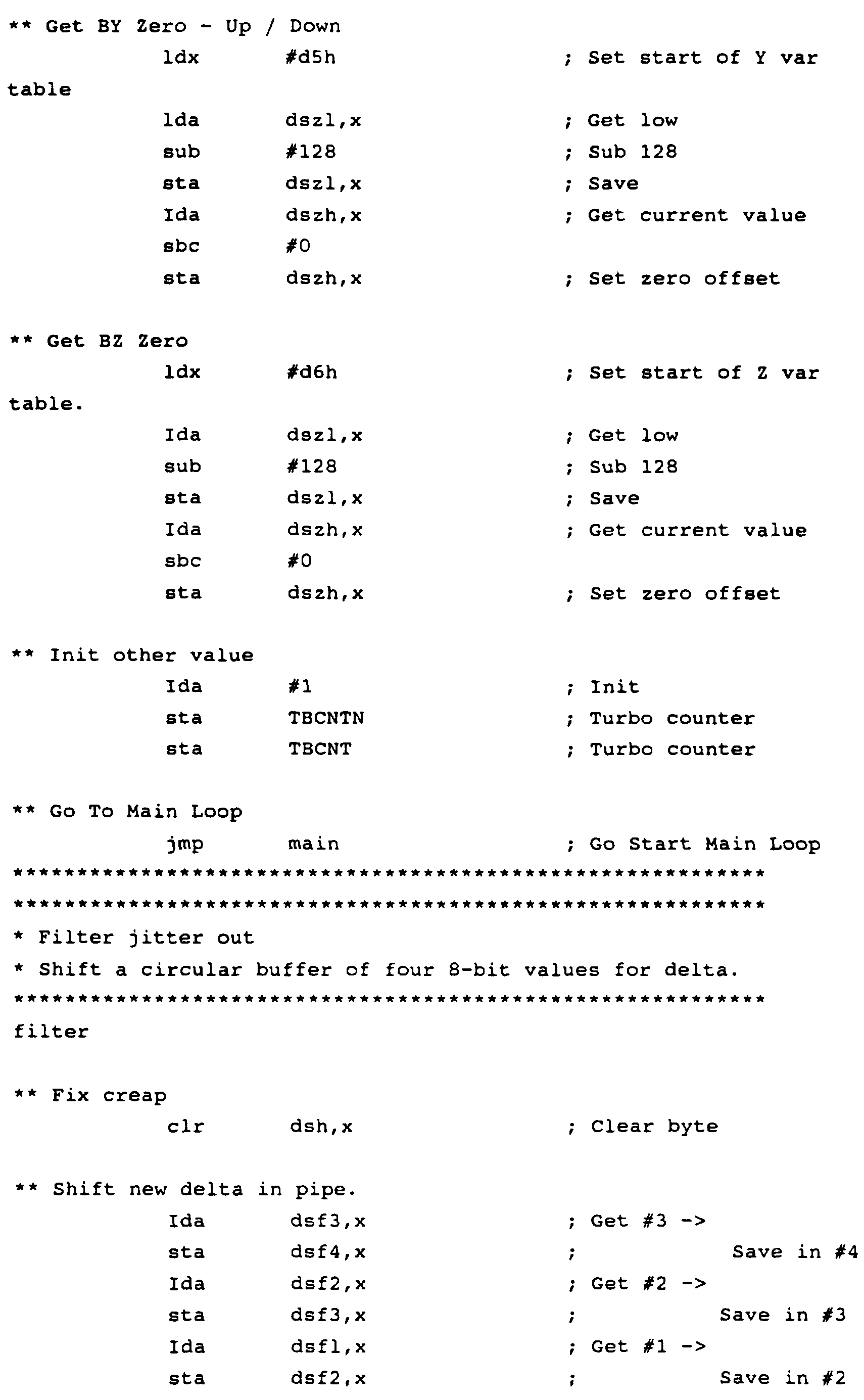

n


t


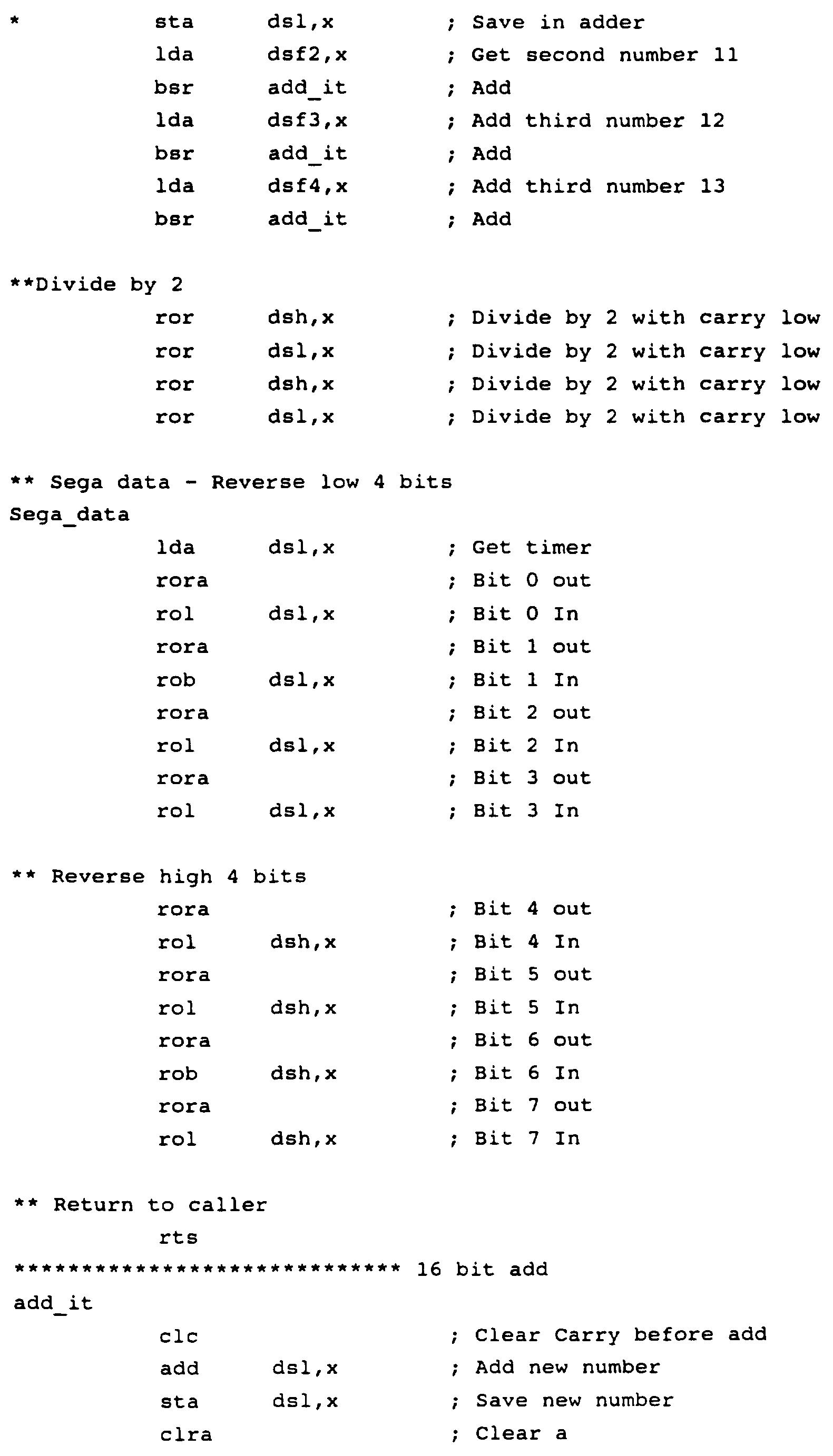


Claims
1. A circuit comprising:
a first photodiode having a cathode connected to a source of a first voltage;
a second photodiode having a cathode connected to the anode of said first photodiode, said second photodiode having an anode connected to a source of a second voltage; and
a ratiometric sensor output line connected to a junction between the anode of said first
photodiode and the cathode of said second
photodiode;
wherein a voltage on said ratiometric sensor output line is proportional to the ratio of the amount of light incident on the second photodiode to the sum of the amount of light incident on the first photodiode and the amount of light incident on the second photodiode.
2. The circuit of Claim 1 wherein said voltage source is at an approximately constant power supply voltage.
3. The circuit of Claim 1 wherein said second voltage source is at an approximately constant voltage of zero.
4. The circuit of Claim 1 further comprising an analog-to-digital converter, wherein said ratiometric sensor output line is connected to an input terminal of said analog-to-digital converter.
5. The circuit of Claim 4 wherein said
analog-to-digital converter is a voltage controlled analog-to-digital converter.
6. The circuit of Claim 5 wherein said voltage controlled analog-to-digital converter is a voltage controlled oscillator.
7. The circuit of Claim 6 wherein said voltage controlled oscillator includes a 555 timer.
8. The circuit of Claim 6:
wherein said voltage controlled oscillator includes a resistor and a capacitor; and
further wherein a junction between said resistor and said capacitor is connected to an input terminal of said voltage controlled
oscillator and to an output terminal of said voltage controlled oscillator.
9. The circuit of Claim 8:
wherein said capacitor is a junction capacitor of a gate of a field-effect-transistor; and
further wherein said gate is connected to a terminal of a microprocessor.
10. The circuit of Claim 8:
wherein said resistor is a pull-down resistor in said microprocessor; and
further wherein said resistor is connected to an input terminal of the microprocessor.
11. The circuit of Claim 4:
wherein said analog-to-digital converter is a current controlled analog-to-digital converter; and
further wherein said ratiometric sensor output line is coupled by a voltage controlled
current amplifier to an input terminal of said current controlled analog-to-digital converter.
12. The circuit of Claim 11 wherein said current controlled analog-to-digital converter is a current controlled oscillator.
13. The circuit of Claim 12 wherein said current controlled oscillator is included inside a game port of a personal computer.
14. The circuit of Claim 12 wherein said voltage controlled current amplifier includes a Darlington transistor.
15. A circuit comprising:
a ratiometric sensor having a first input line connected to a first voltage source, a second input line connected to a second voltage source and a ratiometric sensor output line;
a current amplifier having an input terminal connected to said ratiometric sensor output line; a personal computer having a game port, an analog input terminal of said game port being connected to an output line of said current amplifier.
16. The circuit of Claim 15:
wherein said ratiometric sensor includes a potentiometer and a photodiode; and
further wherein a terminal of said potentiometer and the cathode of said photodiode are connected to the ratiometric sensor output line.
17. The circuit of Claim 15:
wherein said ratiometric sensor includes a first photodiode and a second photodiode; and
further wherein an anode of said first photodiode and a cathode of said second photodiode are connected to said ratiometric sensor output line.
18. The circuit of Claim 15 wherein said current amplifier is a voltage-controlled current amplifier.
19. The circuit of Claim 18 wherein said voltage-controlled current amplifier includes a Darlington transistor.
20. The circuit of Claim 18 wherein said game port comprises a timer, an input terminal of said timer being connected to the output line of said voltage controlled current amplifier.
21. The circuit of Claim 18 wherein said game port is sensitive to an analog direct current at said input terminal.
22. A circuit comprising:
a ratiometric sensor comprising a signal sensor, a first reference voltage line, a second reference voltage line and a ratiometric sensor output line, said ratiometric sensor having a first equivalent resistance between said first reference voltage line and said ratiometric sensor output line, said ratiometric sensor further having a second equivalent resistance between said second reference voltage line and said ratiometric sensor output line;
an analog-to-digital converter having a signal output line and a signal input terminal,
said signal input terminal being coupled to said ratiometric sensor output line;
wherein said ratiometric sensor supplies a ratiometric voltage on said ratiometric sensor output line, said ratiometric voltage being proportional to the ratio of said second
equivalent resistance to the sum of said first equivalent resistance and said second equivalent resistance; and
wherein said analog-to-digital converter receives the analog signal on said signal input terminal and supplies a corresponding digital signal on said signal output line.
23. The circuit of Claim 22 wherein said
ratiometric sensor comprises a potentiometer coupled between said first reference voltage line and said ratiometric sensor output line and wherein said signal sensor is coupled between said second reference voltage line and said ratiometric sensor output line.
24. The circuit of Claim 22 wherein said analog to digital converter comprises a Darlington transistor.
25. The circuit of Claim 22 wherein said
ratiometric sensor comprises a first signal sensor coupled between said ratiometric sensor output line and said first reference voltage line and further wherein said ratiometric sensor comprises a second signal sensor coupled between said second reference voltage line and said ratiometric sensor output line.
26. The circuit of Claim 22 wherein said
analog-to-digital converter comprises a monostable multivibrator.
27. The circuit of Claim 26 wherein said
monostable multivibrator comprises a "555" timer.
28. The circuit of Claim 22 wherein said signal output line is coupled to a terminal of a
microprocessor.
29. The circuit of Claim 28:
wherein said analog-to-digital converter comprises a resistor and a capacitor connected to each other; and
further wherein said ratiometric sensor output line is coupled to a junction between said resistor and said capacitor.
30. The circuit of Claim 28 wherein an output terminal of said microprocessor is coupled to an infrared transmitter.
31. A method comprising:
connecting a cathode of a first photodiode to a source of a first voltage;
connecting an anode of said first photodiode to a cathode of a second photodiode;
connecting an anode of said second photodiode to a source of a second voltage; and
connecting a ratiometric sensor output line to a junction between the anode of said first photodiode and the cathode of said second
photodiode.
32. The method of Claim 31 further comprising connecting said ratiometric sensor output line to an input terminal of an analog-to-digital converter.
33. A method comprising:
connecting a first voltage source to a first input line of a ratiometric sensor;
connecting a second voltage source to a second input line of said ratiometric sensor;
connecting an input terminal of a voltage control current amplifier to a ratiometric sensor output line of said ratiometric sensor; and
connecting an analog input terminal of a game port of a personal computer to an output line of said voltage control current amplifier.
34. A circuit comprising:
a first photodiode having a cathode connected to a source of a first voltage;
an electronic component with an impedance, said electronic component having a first terminal connected to the anode of said first photodiode, said electronic component having a second terminal connected to a source of a second voltage; and
a ratiometric sensor output line connected to a junction between the anode of said first
photodiode and the first terminal of said
electronic component;
wherein a voltage on said ratiometric sensor output line is proportional to the ratio of the equivalent resistance of the first photodiode to the sum of the equivalent resistances of the first photodiode and the electronic component.
35. The circuit of Claim 34 wherein said
electronic component is a second photodiode.
AMENDED CLAIMS
[received by the International Bureau on 4 April 1996 (04.04.96);
original claims 1-3, 9, 10, 22 and 24 amended;
original claims 15-21, 23 and 25-35 cancelled;
new claims 36-45 added;
remaining claims unchanged (7pages)]
1. A circuit comprising:
a first photodiode having a cathode and an anode;
a second photodiode having an anode and a cathode said cathode of said second photodiode being coupled to said anode of said first
photodiode; and
a ratiometric sensor output line coupled to a junction between said anode of said first
photodiode and said cathode of said second
photodiode;
wherein a voltage level of an electrical signal on said ratiometric sensor output line is proportional to a ratio of an amount of light incident on said second photodiode to a sum of said amount of light incident on said second photodiode and another amount of light incident on said first photodiode when a voltage source is coupled between said cathode of said first
photodiode and said anode of said second
photodiode; and
further wherein noise m light incident on said first photodiode and on said second
photodiode has a substantially equal effect on a numerator and a denominator of said ratio to thereby allow said voltage level of said
electrical signal on said ratiometric sensor output line to remain substanrially unaffected by said noise.
2. The circuit of Claim 1 wherein said voltage source is at an approximately constant power supply voltage level.
3. The circuit of Claim 1 wherein said anode of said second photodiode is at an approximately constant voltage of zero. 4. The circuit of Claim 1 further comprising an analog-to-digital converter, wherein said ratiometric sensor output line is connected to an input terminal of said analog-to-digital converter. 5. The circuit of Claim 4 wherein said
analog-to-digital converter is a voltage controlled analog-to-digital converter.
6. The circuit of Claim 5 wherein said voltage controlled analog-to-digital converter is a voltage controlled oscillator.
7. The circuit of Claim 6 wherein said voltage controlled oscillator includes a 555 timer.
8. The circuit of Claim 6:
wherein said voltage controlled oscillator includes a resistor and a capacitor; and
further wherein a junction between said resistor and said capacitor is connected to an input terminal of said voltage controlled
oscillator and to an output terminal of said voltage controlled oscillator. 9. The circuit of Claim 8:
wherein said capacitor is inside a microprocessor .
10. The circuit of Claim 8:
wherein said resistor is a pull-down resistor in a microprocessor; and
further wherein said resistor is connected to an input terminal of the microprocessor.
11. The circuit of Claim 4:
wherein said analog-to-digital converter is a current controlled analog-to-digital converter; and
further wherein said ratiometric sensor output line is coupled by a voltage controlled current amplifier to an input terminal of said current controlled analog-to-digital converter.
12. The circuit of Claim 11 wherein said current controlled analog-to-digital converter is a current controlled oscillator.
13. The circuit of Claim 12 wherein said current controlled oscillator is included inside a game port of a personal computer.
14. The circuit of Claim 12 wherein said voltage controlled current amplifier includes a Darlington transistor. 22. A circuit comprising:
a ratiometric sensor comprising a signal sensor, a first reference voltage line, a second reference voltage line and a ratiometric sensor output line, said ratiometric sensor having a first equivalent resistance between said first reference voltage line and said ratiometric sensor output line, said ratiometric sensor further having a second equivalent resistance between said second reference voltage line and said ratiometric sensor output line; and
a voltage controlled current amplifier consisting essentially of:
a pnp transistor having a base, a collector and an emitter, said base being coupled to said ratiometric sensor output line;
a first resistor coupled between said first reference voltage line and said emitter to thereby limit current supplied at said collector; and
a second resistor coupled between said first reference voltage line and said
collector to thereby allow current to be supplied at said collector when said pnp transistor is off.
24. The circuit of Claim 22 further comprising a Darlington pair wherein said pnp transistor is included in said Darlington pair.
36. The circuit of Claim 1 further comprising a light emitting diode for generating at least light incident on said first photodiode and on said second photodiode.
37. The circuit of Claim 36 wherein said light emitting diode has two terminals, and said voltage source is coupled between said two terminals of said light emitting diode.
38. The circuit of Claim 36 further comprising a voltage enable line and a ground reference voltage line, wherein said light emitting diode has a terminal coupled to said voltage enable line and further wherein said light emitting diode has another terminal coupled to said ground reference voltage line.
39. The circuit of Claim 38 wherein said anode of said second photodiode is coupled to said ground reference voltage line.
40. The circuit of Claim 22 comprising a
plurality of ratiometric sensors for detection of movement along a plurality of axes.
41. The circuit of Claim 1 further comprising a first light emitting diode and a second light emitting diode;
wherein said first light emitting diode generates light incident on said first photodiode; and
further wherein said second light emitting diode generates light incident on said second photodiode.
42. The circuit of Claim 41 further comprising: a first reference voltage line capable of being coupled to a first voltage source; and
a second reference voltage line capable of being coupled to a second voltage source;
wherein said first light emitting diode and a second light emitting diode are coupled in
parallel between said first reference voltage line and said second reference voltage line.
43. The circuit of Claim 41 further comprising: a first reference voltage line capable of being coupled to a first voltage source; and
a second reference voltage line capable of being coupled to a second voltage source;
wherein said first light emitting diode and a second light emitting diode are coupled in series
between said first reference voltage line and said second reference voltage line.
44. A circuit comprising:
a first photosensitive element having a first terminal and a second terminal;
a second photosensitive element having a first terminal and a second terminal, said first terminal of said second photosensitive element being coupled to said second terminal of said first photosensitive element; and
a ratiometric sensor output line coupled to a junction between said second terminal of said first photosensitive element and said first terminal of said second photosensitive element; wherein a voltage level of an electrical signal on said ratiometric sensor output line is proportional to a ratio of an amount of light incident on said second photosensitive element to a sum of said amount of light incident on said second photosensitive element and another amount of light incident on said first photosensitive element when a voltage source is coupled between said first terminal of said first photosensitive element and said second terminal of said second photosensitive element; and
further wherein noise in light incident on said first photosensitive element and on said second photosensitive element has a substantially equal effect on a numerator and a denominator of said ratio to thereby allow said voltage level of said electrical signal on said ratiometric sensor output line to remain substantially unaffected by said noise.
45. The circuit of Claim 44 wherein said voltage source is at an approximately constant power supply voltage level.
Priority Applications (1)
| Application Number | Priority Date | Filing Date | Title |
|---|---|---|---|
| AU42908/96A AU4290896A (en) | 1994-12-19 | 1995-12-12 | Method and apparatus for generating ratiometric control signals |
Applications Claiming Priority (2)
| Application Number | Priority Date | Filing Date | Title |
|---|---|---|---|
| US359,306 | 1994-12-19 | ||
| US08/359,306 US5650608A (en) | 1991-12-05 | 1994-12-19 | Method and apparatus for generating ratiometric control signals |
Publications (1)
| Publication Number | Publication Date |
|---|---|
| WO1996019821A1 true WO1996019821A1 (en) | 1996-06-27 |
Family
ID=23413256
Family Applications (1)
| Application Number | Title | Priority Date | Filing Date |
|---|---|---|---|
| PCT/US1995/015611 WO1996019821A1 (en) | 1994-12-19 | 1995-12-12 | Method and apparatus for generating ratiometric control signals |
Country Status (4)
| Country | Link |
|---|---|
| US (2) | US5650608A (en) |
| AU (1) | AU4290896A (en) |
| TW (1) | TW265415B (en) |
| WO (1) | WO1996019821A1 (en) |
Cited By (3)
| Publication number | Priority date | Publication date | Assignee | Title |
|---|---|---|---|---|
| US6076734A (en) * | 1997-10-07 | 2000-06-20 | Interval Research Corporation | Methods and systems for providing human/computer interfaces |
| US6164541A (en) * | 1997-10-10 | 2000-12-26 | Interval Research Group | Methods and systems for providing human/computer interfaces |
| US6256638B1 (en) | 1998-04-14 | 2001-07-03 | Interval Research Corporation | Printable interfaces and digital linkmarks |
Families Citing this family (27)
| Publication number | Priority date | Publication date | Assignee | Title |
|---|---|---|---|---|
| US5650608A (en) * | 1991-12-05 | 1997-07-22 | Tv Interactive Data Corporation | Method and apparatus for generating ratiometric control signals |
| US6681029B1 (en) | 1993-11-18 | 2004-01-20 | Digimarc Corporation | Decoding steganographic messages embedded in media signals |
| US6411725B1 (en) | 1995-07-27 | 2002-06-25 | Digimarc Corporation | Watermark enabled video objects |
| US6408331B1 (en) | 1995-07-27 | 2002-06-18 | Digimarc Corporation | Computer linking methods using encoded graphics |
| US5818037A (en) * | 1996-04-09 | 1998-10-06 | Tv Interactive Data Corporation | Controller using a flexible element to vary light transferred to a photosensitive element |
| US6053814A (en) * | 1997-12-04 | 2000-04-25 | Logitech, Inc. | System and method for automatically adjusting game controller sensitivity to player inputs |
| DE19818315C1 (en) * | 1998-04-23 | 1999-09-16 | Siemens Ag | Radiometric sensor signal measuring device |
| US6265790B1 (en) * | 1998-10-07 | 2001-07-24 | Intel Corporation | Computer system fan circuit |
| WO2000022881A2 (en) | 1998-10-12 | 2000-04-20 | Control Devices, Inc. | Ambient light sensor |
| US7624632B1 (en) * | 1999-08-17 | 2009-12-01 | Lockheed Martin Corporation | Constant-temperature-difference flow sensor, and integrated flow, temperature, and pressure sensor |
| US7111168B2 (en) | 2000-05-01 | 2006-09-19 | Digimarc Corporation | Digital watermarking systems |
| US7003598B2 (en) * | 2002-09-18 | 2006-02-21 | Bright Entertainment Limited | Remote control for providing interactive DVD navigation based on user response |
| US20060164932A1 (en) * | 2002-09-18 | 2006-07-27 | Bright Entertainment Limited | Media control unit for providing interactive experience with audiovisual content of dvd |
| US20040140998A1 (en) * | 2002-11-01 | 2004-07-22 | Gravina Craig S. | Controller and removable user interface (rui) for controlling media event |
| US20040140997A1 (en) * | 2002-11-01 | 2004-07-22 | Gravina Craig S. | Controller and removable user interface (rui) for media presentation |
| US20050060238A1 (en) * | 2002-11-01 | 2005-03-17 | Pushplay Interactive, Llc | Controller and peripheral user interface (pui) for media event |
| US20050005043A1 (en) * | 2002-11-01 | 2005-01-06 | Pushplay Interactive, Llc | Controller and removable user interface (RUI) for media event and additional media content |
| US20050175324A1 (en) * | 2002-11-01 | 2005-08-11 | Gravina Craig S. | Presenting content of a DVD using console and overlay |
| US20040125075A1 (en) * | 2002-12-31 | 2004-07-01 | Diercks Richard A. | DVD remote control with interchangeable, title-specific interactive panels |
| US20040217258A1 (en) * | 2003-04-30 | 2004-11-04 | Clugston P. Edward | Solar sensor including reflective element to transform the angular response |
| US6972620B2 (en) | 2004-02-19 | 2005-12-06 | Optical Communication Products, Inc. | Post amplifier array integrated circuit |
| US7441569B2 (en) * | 2005-04-28 | 2008-10-28 | Robertshaw Controls Company | Will call wireless tank level monitoring system |
| CN200950249Y (en) * | 2005-12-29 | 2007-09-19 | 郑国书 | Mouse with the second left key having double click function of left key |
| EP2037218B1 (en) * | 2007-09-11 | 2014-10-15 | EM Microelectronic-Marin SA | Electronic circuit for measuring a physical parameter supplying an analogue measurement signal depending on the input voltage |
| JP2009074855A (en) * | 2007-09-19 | 2009-04-09 | Oki Semiconductor Co Ltd | Photodetection device |
| US20090243863A1 (en) * | 2008-03-31 | 2009-10-01 | Robertshaw Controls Company | Intrinsically Safe Cellular Tank Monitor For Liquified Gas and Cryogenic Liquids |
| US8006905B2 (en) * | 2008-04-18 | 2011-08-30 | Intermec Ip Corp. | Method of reducing noise in an optically read image using an optical collection device |
Citations (3)
| Publication number | Priority date | Publication date | Assignee | Title |
|---|---|---|---|---|
| US4316155A (en) * | 1979-09-05 | 1982-02-16 | The Bendix Corporation | Voltage controlled oscillator having ratiometric and temperature compensation |
| US5166819A (en) * | 1989-02-23 | 1992-11-24 | Alcatel N.V. | Front end for a broadband optical receiver |
| US5288078A (en) * | 1988-10-14 | 1994-02-22 | David G. Capper | Control interface apparatus |
Family Cites Families (77)
| Publication number | Priority date | Publication date | Assignee | Title |
|---|---|---|---|---|
| US2415168A (en) * | 1944-12-04 | 1947-02-04 | Samuel C Hurley Jr | Electronic timer |
| US3096650A (en) * | 1961-08-29 | 1963-07-09 | Barnes Eng Co | A. c. biased thermistor bolometers |
| US3360653A (en) * | 1964-10-22 | 1967-12-26 | Transmarine Corp | Photoelectric document authenticating apparatus with age and color compensation |
| US3371424A (en) * | 1965-03-25 | 1968-03-05 | Northern Electric Co | Reference attitude indicating device |
| US3621268A (en) * | 1967-12-19 | 1971-11-16 | Int Standard Electric Corp | Reflection type contactless touch switch having housing with light entrance and exit apertures opposite and facing |
| GB1243836A (en) * | 1968-11-07 | 1971-08-25 | D Mac Ltd | Radiation monitoring device |
| US3526775A (en) * | 1968-12-10 | 1970-09-01 | Int Standard Electric Corp | Contactless touch switch responsive to interruptions of indirect light |
| US3863067A (en) * | 1972-07-24 | 1975-01-28 | Cornelius Leonard Gooley | Orientation indicating apparatus |
| SE367868B (en) * | 1972-10-26 | 1974-06-10 | Ericsson Telefon Ab L M | |
| US4040743A (en) * | 1975-09-22 | 1977-08-09 | Howell Laboratories, Incorporated | Method and apparatus for measuring the brightness of pulp slurry |
| US4013342A (en) * | 1975-12-19 | 1977-03-22 | Narodny Leo H | Keyboard using optical switching |
| US4154000A (en) * | 1976-01-12 | 1979-05-15 | The Brunton Company | Remote level sensing instrument |
| US4049964A (en) * | 1976-04-01 | 1977-09-20 | Cavitron Corporation | Optical switching device |
| US4148014A (en) * | 1977-04-06 | 1979-04-03 | Texas Instruments Incorporated | System with joystick to control velocity vector of a display cursor |
| SU800637A1 (en) * | 1979-03-05 | 1981-01-30 | Предприятие П/Я Х-5827 | Level checker |
| US4307516A (en) * | 1980-02-07 | 1981-12-29 | The United States Of America As Represented By The Secretary Of The Army | Directional two-axis differential optical inclinometer |
| EP0069185B1 (en) * | 1981-07-06 | 1985-10-09 | Battelle Memorial Institute | Photo-electric control device |
| US4430526A (en) * | 1982-01-25 | 1984-02-07 | Bell Telephone Laboratories, Incorporated | Interactive graphics transmission system employing an adaptive stylus for reduced bandwidth |
| US4480182A (en) * | 1982-03-16 | 1984-10-30 | Burroughs Corporation | Single plane optical membrane switch and keyboard |
| US4685678A (en) * | 1982-08-13 | 1987-08-11 | Bally Manufacturing Corporation | Position transducer system for a joystick |
| US4514732A (en) * | 1982-08-23 | 1985-04-30 | General Electric Company | Technique for increasing battery life in remote control transmitters |
| DE3236436C1 (en) * | 1982-10-01 | 1984-03-01 | Fraunhofer-Gesellschaft zur Förderung der angewandten Forschung e.V., 8000 München | Spirit level |
| US4533827A (en) * | 1982-10-06 | 1985-08-06 | Texas A&M University | Optical joystick |
| DE3303103A1 (en) * | 1983-01-31 | 1984-08-02 | Siemens AG, 1000 Berlin und 8000 München | Power semiconductor module and method of triggering it |
| US4701048A (en) * | 1983-02-23 | 1987-10-20 | Canon Kabushiki Kaisha | Input circuit for distance measuring apparatus |
| US4686361A (en) * | 1983-03-08 | 1987-08-11 | Bard Arnold D | Joystick control unit |
| US4565999A (en) * | 1983-04-01 | 1986-01-21 | Prime Computer, Inc. | Light pencil |
| DE3338024A1 (en) * | 1983-10-20 | 1985-05-02 | Standard Elektrik Lorenz Ag, 7000 Stuttgart | AMPLIFIER WITH CURRENT-VOLTAGE CONVERSION, IN PARTICULAR PRE-AMPLIFIER OF AN OPTICAL RECEIVER |
| US4866602A (en) * | 1983-11-02 | 1989-09-12 | Microsoft Corporation | Power supply for a computer peripheral device which positions a cursor on a computer display |
| FI79906C (en) * | 1984-05-09 | 1990-03-12 | Refimex Oy | Device for indicating an angle or direction |
| GB2159650B (en) * | 1984-05-29 | 1988-02-17 | New Zealand Dev Finance | Electronic switch |
| US4755801A (en) * | 1984-06-18 | 1988-07-05 | Eureka Developments Pty. Limited | Bubble movement detector security system |
| US4682159A (en) * | 1984-06-20 | 1987-07-21 | Personics Corporation | Apparatus and method for controlling a cursor on a computer display |
| NL8500817A (en) * | 1984-10-11 | 1986-05-01 | Nieaf Smitt B V | Electro-optical level for testing horizontals and verticals - has semiconductor plate to detect deflection of light guide in column of liquid |
| SU1244489A1 (en) * | 1984-11-20 | 1986-07-15 | Предприятие П/Я В-8543 | Level indicator |
| DE3672631D1 (en) * | 1985-02-28 | 1990-08-23 | Siemens Ag | METHOD FOR DETERMINING THE POSITION OF AN OBJECT IN AN AUTOMATED MANUFACTURING METHOD AND DEVICE FOR IMPLEMENTING THE METHOD. |
| US4642459A (en) * | 1985-05-17 | 1987-02-10 | International Business Machines Corporation | Light pen input system having two-threshold light sensing |
| US4677428A (en) * | 1985-06-07 | 1987-06-30 | Hei, Inc. | Cordless light pen |
| US4712885A (en) * | 1985-10-31 | 1987-12-15 | Loral Electro-Optical Systems, Inc. | Laser diode optical system |
| US4795900A (en) * | 1986-03-27 | 1989-01-03 | Sadao Kokubu | Optical switch device employing a fluorescent substance with a radioactive element as a light source |
| US4787051A (en) * | 1986-05-16 | 1988-11-22 | Tektronix, Inc. | Inertial mouse system |
| US4692612A (en) * | 1986-06-13 | 1987-09-08 | Karel Havel | Switch position detector and indicator with multicolor light emitter |
| DE3770358D1 (en) * | 1986-07-21 | 1991-07-04 | Siemens Ag | OPTICAL OVERLAY RECEIVER, IN PARTICULAR PHASE LEVEL MODULATED LIGHT. |
| US4746879A (en) * | 1986-08-28 | 1988-05-24 | Ma John Y | Digitally temperature compensated voltage-controlled oscillator |
| JPS6363905A (en) * | 1986-09-05 | 1988-03-22 | Nikon Corp | Photoelectric sensor used in positioning device |
| US4748323A (en) * | 1987-03-23 | 1988-05-31 | Holiday Morton J | Joystick device with photoelectric tilt and push button detection |
| US4839838A (en) * | 1987-03-30 | 1989-06-13 | Labiche Mitchell | Spatial input apparatus |
| GB2205941B (en) * | 1987-06-18 | 1991-08-07 | Ibm | Manually-operated control device |
| US4939482A (en) * | 1987-06-24 | 1990-07-03 | Eg&G, Inc. | Remote optical sensing device and method |
| US4862172A (en) * | 1987-09-14 | 1989-08-29 | Texas Scottish Rite Hospital For Crippled Children | Computer control apparatus including a gravity referenced inclinometer |
| US5068645A (en) * | 1987-10-14 | 1991-11-26 | Wang Laboratories, Inc. | Computer input device using an orientation sensor |
| US5142655A (en) * | 1987-10-14 | 1992-08-25 | Wang Laboratories, Inc. | Computer input device using an orientation sensor |
| US5363120A (en) * | 1987-10-14 | 1994-11-08 | Wang Laboratories, Inc. | Computer input device using orientation sensor |
| US4935621A (en) * | 1987-10-30 | 1990-06-19 | Pikulski Joseph L | Optical switch with collimating lenses, antifreeze and/or index matching fluid for control of electrical equipment |
| FI80788C (en) * | 1987-11-09 | 1990-07-10 | Metrum Oy | Method and apparatus for indicating a direction or angle |
| NL8702749A (en) * | 1987-11-18 | 1989-06-16 | Philips Nv | REMOTE CONTROL SYSTEM WITH AWAKE SIGNAL. |
| US4864647A (en) * | 1987-12-18 | 1989-09-05 | Modcom Corporation | Wireless infrared remote control extender |
| US4883926A (en) * | 1988-04-21 | 1989-11-28 | Hewlett-Packard Company | Stylus switch |
| WO1990005356A1 (en) * | 1988-11-04 | 1990-05-17 | Wang Laboratories, Inc. | Computer input device using an orientation sensor |
| US5045843B1 (en) * | 1988-12-06 | 1996-07-16 | Selectech Ltd | Optical pointing device |
| US5063376A (en) * | 1989-05-05 | 1991-11-05 | Chang Ronald G | Numeric mouse one hand controllable computer peripheral pointing device |
| JPH0758804B2 (en) * | 1989-05-17 | 1995-06-21 | 株式会社東芝 | Photo coupler device |
| US5117099A (en) * | 1989-09-01 | 1992-05-26 | Schmidt Terrence C | Ambient light rejecting quad photodiode sensor |
| JPH0738648B2 (en) * | 1989-10-06 | 1995-04-26 | 富士通株式会社 | Optical signal relay transmission control system |
| GB2238382B (en) * | 1989-11-03 | 1993-09-01 | Sure Right Webb Ltd | Level detecting devices |
| US5266949A (en) * | 1990-03-29 | 1993-11-30 | Nokia Mobile Phones Ltd. | Lighted electronic keyboard |
| US5059958A (en) * | 1990-04-10 | 1991-10-22 | Jacobs Jordan S | Manually held tilt sensitive non-joystick control box |
| US4994669A (en) * | 1990-07-29 | 1991-02-19 | Stern Michael A | Opto-electrical joystick switch having a resilient, rigidly mounted central shaft |
| US5086197A (en) * | 1990-09-17 | 1992-02-04 | Liou Kwang Wan | Optical encoding method and device |
| US5096650A (en) * | 1991-02-28 | 1992-03-17 | Network Graphics, Inc. | Method of forming paperboard containers |
| US5223709A (en) * | 1991-09-03 | 1993-06-29 | Honeywell Inc. | Spherical optical encoder for detecting the position and motion about three mutual orthogonal axes |
| US5459489A (en) * | 1991-12-05 | 1995-10-17 | Tv Interactive Data Corporation | Hand held electronic remote control device |
| US5650608A (en) * | 1991-12-05 | 1997-07-22 | Tv Interactive Data Corporation | Method and apparatus for generating ratiometric control signals |
| US5297061A (en) * | 1993-05-19 | 1994-03-22 | University Of Maryland | Three dimensional pointing device monitored by computer vision |
| US5384459A (en) * | 1993-06-01 | 1995-01-24 | Motorola, Inc. | Illuminated switch and keypad assembly having a light gradient and a light conductive elastomeric assembly |
| US5355147A (en) * | 1993-10-04 | 1994-10-11 | Donald Lear | Ergonomic computer mouse |
| US5621207A (en) * | 1994-08-29 | 1997-04-15 | Hasbro, Inc. | Optical joystick using a plurality of multiplexed photoemitters and a corresponding photodetector |
-
1994
- 1994-12-19 US US08/359,306 patent/US5650608A/en not_active Expired - Fee Related
-
1995
- 1995-02-25 TW TW084101764A patent/TW265415B/en active
- 1995-12-12 AU AU42908/96A patent/AU4290896A/en not_active Abandoned
- 1995-12-12 WO PCT/US1995/015611 patent/WO1996019821A1/en active Application Filing
-
1996
- 1996-11-19 US US08/752,085 patent/US5973313A/en not_active Expired - Fee Related
Patent Citations (3)
| Publication number | Priority date | Publication date | Assignee | Title |
|---|---|---|---|---|
| US4316155A (en) * | 1979-09-05 | 1982-02-16 | The Bendix Corporation | Voltage controlled oscillator having ratiometric and temperature compensation |
| US5288078A (en) * | 1988-10-14 | 1994-02-22 | David G. Capper | Control interface apparatus |
| US5166819A (en) * | 1989-02-23 | 1992-11-24 | Alcatel N.V. | Front end for a broadband optical receiver |
Cited By (8)
| Publication number | Priority date | Publication date | Assignee | Title |
|---|---|---|---|---|
| US6076734A (en) * | 1997-10-07 | 2000-06-20 | Interval Research Corporation | Methods and systems for providing human/computer interfaces |
| US6439459B1 (en) | 1997-10-07 | 2002-08-27 | Interval Research Corporation | Methods and systems for providing human/computer interfaces |
| US6518950B1 (en) | 1997-10-07 | 2003-02-11 | Interval Research Corporation | Methods and systems for providing human/computer interfaces |
| US6540141B1 (en) | 1997-10-07 | 2003-04-01 | Interval Research Corporation | Methods and systems for providing human/computer interfaces |
| US6587859B2 (en) | 1997-10-07 | 2003-07-01 | Interval Research Corporation | Printable interfaces and digital linkmarks |
| US6989816B1 (en) | 1997-10-07 | 2006-01-24 | Vulcan Patents Llc | Methods and systems for providing human/computer interfaces |
| US6164541A (en) * | 1997-10-10 | 2000-12-26 | Interval Research Group | Methods and systems for providing human/computer interfaces |
| US6256638B1 (en) | 1998-04-14 | 2001-07-03 | Interval Research Corporation | Printable interfaces and digital linkmarks |
Also Published As
| Publication number | Publication date |
|---|---|
| TW265415B (en) | 1995-12-11 |
| US5973313A (en) | 1999-10-26 |
| AU4290896A (en) | 1996-07-10 |
| US5650608A (en) | 1997-07-22 |
Similar Documents
| Publication | Publication Date | Title |
|---|---|---|
| US5973313A (en) | Method and apparatus for generating ratiometric control signals | |
| US5749577A (en) | Perpheral input device with six-axis capability | |
| US6753849B1 (en) | Universal remote TV mouse | |
| US5459489A (en) | Hand held electronic remote control device | |
| US5657012A (en) | Finger operable control device | |
| US5796354A (en) | Hand-attachable controller with direction sensing | |
| US5638092A (en) | Cursor control system | |
| US5521616A (en) | Control interface apparatus | |
| US6603420B1 (en) | Remote control device with motion-based control of receiver volume, channel selection or other parameters | |
| US4524348A (en) | Control interface | |
| US4866602A (en) | Power supply for a computer peripheral device which positions a cursor on a computer display | |
| EP0457541A1 (en) | Control devices | |
| US10379637B2 (en) | Rotational element enabling touch-like gestures | |
| WO1988001417A1 (en) | Analog transducer circuit with digital control | |
| EP0747851A2 (en) | Recursive digital filter using fixed point arithmetic in a pointing device | |
| US6065069A (en) | Circuit for sensing and automatically switching between an internal and external user I/O device | |
| US4056772A (en) | Ion detector | |
| EP0478614B1 (en) | Finger operable control devices | |
| EP0209467A2 (en) | Improved stylus for use with digitizer tablets | |
| KR100403680B1 (en) | A touch type mouse | |
| CA2195317A1 (en) | Position sensing controller and method for generating control signals | |
| US5451983A (en) | Cumputer accessory exhibiting a common input for two separate auxilliary input | |
| WO1991020022A1 (en) | Improvements to joystick assemblies | |
| US5227639A (en) | Infrared-based sensing circuit providing an output simulating the output of a flame rod sensor | |
| EP0121390B1 (en) | Flexible handling of components for manufacture |
Legal Events
| Date | Code | Title | Description |
|---|---|---|---|
| AK | Designated states |
Kind code of ref document: A1 Designated state(s): AU CA CN JP KR |
|
| AL | Designated countries for regional patents |
Kind code of ref document: A1 Designated state(s): AT BE CH DE DK ES FR GB GR IE IT LU MC NL PT SE |
|
| 121 | Ep: the epo has been informed by wipo that ep was designated in this application | ||
| DFPE | Request for preliminary examination filed prior to expiration of 19th month from priority date (pct application filed before 20040101) | ||
| 122 | Ep: pct application non-entry in european phase | ||
| NENP | Non-entry into the national phase |
Ref country code: CA |