US9814591B2 - Flexible anchoring and fusion devices and methods of using the same - Google Patents
Flexible anchoring and fusion devices and methods of using the same Download PDFInfo
- Publication number
- US9814591B2 US9814591B2 US14/967,588 US201514967588A US9814591B2 US 9814591 B2 US9814591 B2 US 9814591B2 US 201514967588 A US201514967588 A US 201514967588A US 9814591 B2 US9814591 B2 US 9814591B2
- Authority
- US
- United States
- Prior art keywords
- bore
- expandable
- elongate member
- vertebra
- elongate
- Prior art date
- Legal status (The legal status is an assumption and is not a legal conclusion. Google has not performed a legal analysis and makes no representation as to the accuracy of the status listed.)
- Active, expires
Links
Images


Classifications
-
- A—HUMAN NECESSITIES
- A61—MEDICAL OR VETERINARY SCIENCE; HYGIENE
- A61F—FILTERS IMPLANTABLE INTO BLOOD VESSELS; PROSTHESES; DEVICES PROVIDING PATENCY TO, OR PREVENTING COLLAPSING OF, TUBULAR STRUCTURES OF THE BODY, e.g. STENTS; ORTHOPAEDIC, NURSING OR CONTRACEPTIVE DEVICES; FOMENTATION; TREATMENT OR PROTECTION OF EYES OR EARS; BANDAGES, DRESSINGS OR ABSORBENT PADS; FIRST-AID KITS
- A61F2/00—Filters implantable into blood vessels; Prostheses, i.e. artificial substitutes or replacements for parts of the body; Appliances for connecting them with the body; Devices providing patency to, or preventing collapsing of, tubular structures of the body, e.g. stents
- A61F2/02—Prostheses implantable into the body
- A61F2/30—Joints
- A61F2/44—Joints for the spine, e.g. vertebrae, spinal discs
- A61F2/441—Joints for the spine, e.g. vertebrae, spinal discs made of inflatable pockets or chambers filled with fluid, e.g. with hydrogel
-
- A—HUMAN NECESSITIES
- A61—MEDICAL OR VETERINARY SCIENCE; HYGIENE
- A61B—DIAGNOSIS; SURGERY; IDENTIFICATION
- A61B17/00—Surgical instruments, devices or methods, e.g. tourniquets
- A61B17/56—Surgical instruments or methods for treatment of bones or joints; Devices specially adapted therefor
- A61B17/58—Surgical instruments or methods for treatment of bones or joints; Devices specially adapted therefor for osteosynthesis, e.g. bone plates, screws, setting implements or the like
- A61B17/68—Internal fixation devices, including fasteners and spinal fixators, even if a part thereof projects from the skin
- A61B17/84—Fasteners therefor or fasteners being internal fixation devices
- A61B17/86—Pins or screws or threaded wires; nuts therefor
- A61B17/8625—Shanks, i.e. parts contacting bone tissue
-
- A—HUMAN NECESSITIES
- A61—MEDICAL OR VETERINARY SCIENCE; HYGIENE
- A61B—DIAGNOSIS; SURGERY; IDENTIFICATION
- A61B17/00—Surgical instruments, devices or methods, e.g. tourniquets
- A61B17/56—Surgical instruments or methods for treatment of bones or joints; Devices specially adapted therefor
- A61B17/58—Surgical instruments or methods for treatment of bones or joints; Devices specially adapted therefor for osteosynthesis, e.g. bone plates, screws, setting implements or the like
- A61B17/68—Internal fixation devices, including fasteners and spinal fixators, even if a part thereof projects from the skin
- A61B17/84—Fasteners therefor or fasteners being internal fixation devices
- A61B17/86—Pins or screws or threaded wires; nuts therefor
- A61B17/864—Pins or screws or threaded wires; nuts therefor hollow, e.g. with socket or cannulated
-
- A—HUMAN NECESSITIES
- A61—MEDICAL OR VETERINARY SCIENCE; HYGIENE
- A61F—FILTERS IMPLANTABLE INTO BLOOD VESSELS; PROSTHESES; DEVICES PROVIDING PATENCY TO, OR PREVENTING COLLAPSING OF, TUBULAR STRUCTURES OF THE BODY, e.g. STENTS; ORTHOPAEDIC, NURSING OR CONTRACEPTIVE DEVICES; FOMENTATION; TREATMENT OR PROTECTION OF EYES OR EARS; BANDAGES, DRESSINGS OR ABSORBENT PADS; FIRST-AID KITS
- A61F2/00—Filters implantable into blood vessels; Prostheses, i.e. artificial substitutes or replacements for parts of the body; Appliances for connecting them with the body; Devices providing patency to, or preventing collapsing of, tubular structures of the body, e.g. stents
- A61F2/02—Prostheses implantable into the body
- A61F2/30—Joints
- A61F2/44—Joints for the spine, e.g. vertebrae, spinal discs
- A61F2/4455—Joints for the spine, e.g. vertebrae, spinal discs for the fusion of spinal bodies, e.g. intervertebral fusion of adjacent spinal bodies, e.g. fusion cages
- A61F2/447—Joints for the spine, e.g. vertebrae, spinal discs for the fusion of spinal bodies, e.g. intervertebral fusion of adjacent spinal bodies, e.g. fusion cages substantially parallelepipedal, e.g. having a rectangular or trapezoidal cross-section
-
- A—HUMAN NECESSITIES
- A61—MEDICAL OR VETERINARY SCIENCE; HYGIENE
- A61F—FILTERS IMPLANTABLE INTO BLOOD VESSELS; PROSTHESES; DEVICES PROVIDING PATENCY TO, OR PREVENTING COLLAPSING OF, TUBULAR STRUCTURES OF THE BODY, e.g. STENTS; ORTHOPAEDIC, NURSING OR CONTRACEPTIVE DEVICES; FOMENTATION; TREATMENT OR PROTECTION OF EYES OR EARS; BANDAGES, DRESSINGS OR ABSORBENT PADS; FIRST-AID KITS
- A61F2/00—Filters implantable into blood vessels; Prostheses, i.e. artificial substitutes or replacements for parts of the body; Appliances for connecting them with the body; Devices providing patency to, or preventing collapsing of, tubular structures of the body, e.g. stents
- A61F2/02—Prostheses implantable into the body
- A61F2/30—Joints
- A61F2/46—Special tools or methods for implanting or extracting artificial joints, accessories, bone grafts or substitutes, or particular adaptations therefor
- A61F2/4603—Special tools or methods for implanting or extracting artificial joints, accessories, bone grafts or substitutes, or particular adaptations therefor for insertion or extraction of endoprosthetic joints or of accessories thereof
- A61F2/4611—Special tools or methods for implanting or extracting artificial joints, accessories, bone grafts or substitutes, or particular adaptations therefor for insertion or extraction of endoprosthetic joints or of accessories thereof of spinal prostheses
-
- A—HUMAN NECESSITIES
- A61—MEDICAL OR VETERINARY SCIENCE; HYGIENE
- A61F—FILTERS IMPLANTABLE INTO BLOOD VESSELS; PROSTHESES; DEVICES PROVIDING PATENCY TO, OR PREVENTING COLLAPSING OF, TUBULAR STRUCTURES OF THE BODY, e.g. STENTS; ORTHOPAEDIC, NURSING OR CONTRACEPTIVE DEVICES; FOMENTATION; TREATMENT OR PROTECTION OF EYES OR EARS; BANDAGES, DRESSINGS OR ABSORBENT PADS; FIRST-AID KITS
- A61F2/00—Filters implantable into blood vessels; Prostheses, i.e. artificial substitutes or replacements for parts of the body; Appliances for connecting them with the body; Devices providing patency to, or preventing collapsing of, tubular structures of the body, e.g. stents
- A61F2/02—Prostheses implantable into the body
- A61F2/30—Joints
- A61F2002/30001—Additional features of subject-matter classified in A61F2/28, A61F2/30 and subgroups thereof
- A61F2002/30003—Material related properties of the prosthesis or of a coating on the prosthesis
- A61F2002/30004—Material related properties of the prosthesis or of a coating on the prosthesis the prosthesis being made from materials having different values of a given property at different locations within the same prosthesis
- A61F2002/30014—Material related properties of the prosthesis or of a coating on the prosthesis the prosthesis being made from materials having different values of a given property at different locations within the same prosthesis differing in elasticity, stiffness or compressibility
-
- A—HUMAN NECESSITIES
- A61—MEDICAL OR VETERINARY SCIENCE; HYGIENE
- A61F—FILTERS IMPLANTABLE INTO BLOOD VESSELS; PROSTHESES; DEVICES PROVIDING PATENCY TO, OR PREVENTING COLLAPSING OF, TUBULAR STRUCTURES OF THE BODY, e.g. STENTS; ORTHOPAEDIC, NURSING OR CONTRACEPTIVE DEVICES; FOMENTATION; TREATMENT OR PROTECTION OF EYES OR EARS; BANDAGES, DRESSINGS OR ABSORBENT PADS; FIRST-AID KITS
- A61F2/00—Filters implantable into blood vessels; Prostheses, i.e. artificial substitutes or replacements for parts of the body; Appliances for connecting them with the body; Devices providing patency to, or preventing collapsing of, tubular structures of the body, e.g. stents
- A61F2/02—Prostheses implantable into the body
- A61F2/30—Joints
- A61F2002/30001—Additional features of subject-matter classified in A61F2/28, A61F2/30 and subgroups thereof
- A61F2002/30003—Material related properties of the prosthesis or of a coating on the prosthesis
- A61F2002/3006—Properties of materials and coating materials
- A61F2002/30092—Properties of materials and coating materials using shape memory or superelastic materials, e.g. nitinol
-
- A—HUMAN NECESSITIES
- A61—MEDICAL OR VETERINARY SCIENCE; HYGIENE
- A61F—FILTERS IMPLANTABLE INTO BLOOD VESSELS; PROSTHESES; DEVICES PROVIDING PATENCY TO, OR PREVENTING COLLAPSING OF, TUBULAR STRUCTURES OF THE BODY, e.g. STENTS; ORTHOPAEDIC, NURSING OR CONTRACEPTIVE DEVICES; FOMENTATION; TREATMENT OR PROTECTION OF EYES OR EARS; BANDAGES, DRESSINGS OR ABSORBENT PADS; FIRST-AID KITS
- A61F2/00—Filters implantable into blood vessels; Prostheses, i.e. artificial substitutes or replacements for parts of the body; Appliances for connecting them with the body; Devices providing patency to, or preventing collapsing of, tubular structures of the body, e.g. stents
- A61F2/02—Prostheses implantable into the body
- A61F2/30—Joints
- A61F2002/30001—Additional features of subject-matter classified in A61F2/28, A61F2/30 and subgroups thereof
- A61F2002/30108—Shapes
- A61F2002/3011—Cross-sections or two-dimensional shapes
- A61F2002/30112—Rounded shapes, e.g. with rounded corners
- A61F2002/30136—Rounded shapes, e.g. with rounded corners undulated or wavy, e.g. serpentine-shaped or zigzag-shaped
-
- A—HUMAN NECESSITIES
- A61—MEDICAL OR VETERINARY SCIENCE; HYGIENE
- A61F—FILTERS IMPLANTABLE INTO BLOOD VESSELS; PROSTHESES; DEVICES PROVIDING PATENCY TO, OR PREVENTING COLLAPSING OF, TUBULAR STRUCTURES OF THE BODY, e.g. STENTS; ORTHOPAEDIC, NURSING OR CONTRACEPTIVE DEVICES; FOMENTATION; TREATMENT OR PROTECTION OF EYES OR EARS; BANDAGES, DRESSINGS OR ABSORBENT PADS; FIRST-AID KITS
- A61F2/00—Filters implantable into blood vessels; Prostheses, i.e. artificial substitutes or replacements for parts of the body; Appliances for connecting them with the body; Devices providing patency to, or preventing collapsing of, tubular structures of the body, e.g. stents
- A61F2/02—Prostheses implantable into the body
- A61F2/30—Joints
- A61F2002/30001—Additional features of subject-matter classified in A61F2/28, A61F2/30 and subgroups thereof
- A61F2002/30316—The prosthesis having different structural features at different locations within the same prosthesis; Connections between prosthetic parts; Special structural features of bone or joint prostheses not otherwise provided for
- A61F2002/30329—Connections or couplings between prosthetic parts, e.g. between modular parts; Connecting elements
- A61F2002/30331—Connections or couplings between prosthetic parts, e.g. between modular parts; Connecting elements made by longitudinally pushing a protrusion into a complementarily-shaped recess, e.g. held by friction fit
- A61F2002/30354—Cylindrically-shaped protrusion and recess, e.g. cylinder of circular basis
-
- A—HUMAN NECESSITIES
- A61—MEDICAL OR VETERINARY SCIENCE; HYGIENE
- A61F—FILTERS IMPLANTABLE INTO BLOOD VESSELS; PROSTHESES; DEVICES PROVIDING PATENCY TO, OR PREVENTING COLLAPSING OF, TUBULAR STRUCTURES OF THE BODY, e.g. STENTS; ORTHOPAEDIC, NURSING OR CONTRACEPTIVE DEVICES; FOMENTATION; TREATMENT OR PROTECTION OF EYES OR EARS; BANDAGES, DRESSINGS OR ABSORBENT PADS; FIRST-AID KITS
- A61F2/00—Filters implantable into blood vessels; Prostheses, i.e. artificial substitutes or replacements for parts of the body; Appliances for connecting them with the body; Devices providing patency to, or preventing collapsing of, tubular structures of the body, e.g. stents
- A61F2/02—Prostheses implantable into the body
- A61F2/30—Joints
- A61F2002/30001—Additional features of subject-matter classified in A61F2/28, A61F2/30 and subgroups thereof
- A61F2002/30316—The prosthesis having different structural features at different locations within the same prosthesis; Connections between prosthetic parts; Special structural features of bone or joint prostheses not otherwise provided for
- A61F2002/30329—Connections or couplings between prosthetic parts, e.g. between modular parts; Connecting elements
- A61F2002/30405—Connections or couplings between prosthetic parts, e.g. between modular parts; Connecting elements made by screwing complementary threads machined on the parts themselves
- A61F2002/30406—Threads machined on spherical, e.g. hemispherical, surfaces
-
- A—HUMAN NECESSITIES
- A61—MEDICAL OR VETERINARY SCIENCE; HYGIENE
- A61F—FILTERS IMPLANTABLE INTO BLOOD VESSELS; PROSTHESES; DEVICES PROVIDING PATENCY TO, OR PREVENTING COLLAPSING OF, TUBULAR STRUCTURES OF THE BODY, e.g. STENTS; ORTHOPAEDIC, NURSING OR CONTRACEPTIVE DEVICES; FOMENTATION; TREATMENT OR PROTECTION OF EYES OR EARS; BANDAGES, DRESSINGS OR ABSORBENT PADS; FIRST-AID KITS
- A61F2/00—Filters implantable into blood vessels; Prostheses, i.e. artificial substitutes or replacements for parts of the body; Appliances for connecting them with the body; Devices providing patency to, or preventing collapsing of, tubular structures of the body, e.g. stents
- A61F2/02—Prostheses implantable into the body
- A61F2/30—Joints
- A61F2002/30001—Additional features of subject-matter classified in A61F2/28, A61F2/30 and subgroups thereof
- A61F2002/30316—The prosthesis having different structural features at different locations within the same prosthesis; Connections between prosthetic parts; Special structural features of bone or joint prostheses not otherwise provided for
- A61F2002/30535—Special structural features of bone or joint prostheses not otherwise provided for
- A61F2002/30581—Special structural features of bone or joint prostheses not otherwise provided for having a pocket filled with fluid, e.g. liquid
- A61F2002/30583—Special structural features of bone or joint prostheses not otherwise provided for having a pocket filled with fluid, e.g. liquid filled with hardenable fluid, e.g. curable in-situ
-
- A—HUMAN NECESSITIES
- A61—MEDICAL OR VETERINARY SCIENCE; HYGIENE
- A61F—FILTERS IMPLANTABLE INTO BLOOD VESSELS; PROSTHESES; DEVICES PROVIDING PATENCY TO, OR PREVENTING COLLAPSING OF, TUBULAR STRUCTURES OF THE BODY, e.g. STENTS; ORTHOPAEDIC, NURSING OR CONTRACEPTIVE DEVICES; FOMENTATION; TREATMENT OR PROTECTION OF EYES OR EARS; BANDAGES, DRESSINGS OR ABSORBENT PADS; FIRST-AID KITS
- A61F2/00—Filters implantable into blood vessels; Prostheses, i.e. artificial substitutes or replacements for parts of the body; Appliances for connecting them with the body; Devices providing patency to, or preventing collapsing of, tubular structures of the body, e.g. stents
- A61F2/02—Prostheses implantable into the body
- A61F2/30—Joints
- A61F2/30767—Special external or bone-contacting surface, e.g. coating for improving bone ingrowth
- A61F2/30771—Special external or bone-contacting surface, e.g. coating for improving bone ingrowth applied in original prostheses, e.g. holes or grooves
- A61F2002/30772—Apertures or holes, e.g. of circular cross section
- A61F2002/30774—Apertures or holes, e.g. of circular cross section internally-threaded
-
- A—HUMAN NECESSITIES
- A61—MEDICAL OR VETERINARY SCIENCE; HYGIENE
- A61F—FILTERS IMPLANTABLE INTO BLOOD VESSELS; PROSTHESES; DEVICES PROVIDING PATENCY TO, OR PREVENTING COLLAPSING OF, TUBULAR STRUCTURES OF THE BODY, e.g. STENTS; ORTHOPAEDIC, NURSING OR CONTRACEPTIVE DEVICES; FOMENTATION; TREATMENT OR PROTECTION OF EYES OR EARS; BANDAGES, DRESSINGS OR ABSORBENT PADS; FIRST-AID KITS
- A61F2/00—Filters implantable into blood vessels; Prostheses, i.e. artificial substitutes or replacements for parts of the body; Appliances for connecting them with the body; Devices providing patency to, or preventing collapsing of, tubular structures of the body, e.g. stents
- A61F2/02—Prostheses implantable into the body
- A61F2/30—Joints
- A61F2/30767—Special external or bone-contacting surface, e.g. coating for improving bone ingrowth
- A61F2/30771—Special external or bone-contacting surface, e.g. coating for improving bone ingrowth applied in original prostheses, e.g. holes or grooves
- A61F2002/30772—Apertures or holes, e.g. of circular cross section
- A61F2002/30777—Oblong apertures
- A61F2002/30779—Oblong apertures arcuate
-
- A—HUMAN NECESSITIES
- A61—MEDICAL OR VETERINARY SCIENCE; HYGIENE
- A61F—FILTERS IMPLANTABLE INTO BLOOD VESSELS; PROSTHESES; DEVICES PROVIDING PATENCY TO, OR PREVENTING COLLAPSING OF, TUBULAR STRUCTURES OF THE BODY, e.g. STENTS; ORTHOPAEDIC, NURSING OR CONTRACEPTIVE DEVICES; FOMENTATION; TREATMENT OR PROTECTION OF EYES OR EARS; BANDAGES, DRESSINGS OR ABSORBENT PADS; FIRST-AID KITS
- A61F2/00—Filters implantable into blood vessels; Prostheses, i.e. artificial substitutes or replacements for parts of the body; Appliances for connecting them with the body; Devices providing patency to, or preventing collapsing of, tubular structures of the body, e.g. stents
- A61F2/02—Prostheses implantable into the body
- A61F2/30—Joints
- A61F2/30767—Special external or bone-contacting surface, e.g. coating for improving bone ingrowth
- A61F2/30771—Special external or bone-contacting surface, e.g. coating for improving bone ingrowth applied in original prostheses, e.g. holes or grooves
- A61F2002/30878—Special external or bone-contacting surface, e.g. coating for improving bone ingrowth applied in original prostheses, e.g. holes or grooves with non-sharp protrusions, for instance contacting the bone for anchoring, e.g. keels, pegs, pins, posts, shanks, stems, struts
- A61F2002/30886—Special external or bone-contacting surface, e.g. coating for improving bone ingrowth applied in original prostheses, e.g. holes or grooves with non-sharp protrusions, for instance contacting the bone for anchoring, e.g. keels, pegs, pins, posts, shanks, stems, struts externally-threaded
-
- A—HUMAN NECESSITIES
- A61—MEDICAL OR VETERINARY SCIENCE; HYGIENE
- A61F—FILTERS IMPLANTABLE INTO BLOOD VESSELS; PROSTHESES; DEVICES PROVIDING PATENCY TO, OR PREVENTING COLLAPSING OF, TUBULAR STRUCTURES OF THE BODY, e.g. STENTS; ORTHOPAEDIC, NURSING OR CONTRACEPTIVE DEVICES; FOMENTATION; TREATMENT OR PROTECTION OF EYES OR EARS; BANDAGES, DRESSINGS OR ABSORBENT PADS; FIRST-AID KITS
- A61F2/00—Filters implantable into blood vessels; Prostheses, i.e. artificial substitutes or replacements for parts of the body; Appliances for connecting them with the body; Devices providing patency to, or preventing collapsing of, tubular structures of the body, e.g. stents
- A61F2/02—Prostheses implantable into the body
- A61F2/30—Joints
- A61F2/30767—Special external or bone-contacting surface, e.g. coating for improving bone ingrowth
- A61F2/30771—Special external or bone-contacting surface, e.g. coating for improving bone ingrowth applied in original prostheses, e.g. holes or grooves
- A61F2002/30878—Special external or bone-contacting surface, e.g. coating for improving bone ingrowth applied in original prostheses, e.g. holes or grooves with non-sharp protrusions, for instance contacting the bone for anchoring, e.g. keels, pegs, pins, posts, shanks, stems, struts
- A61F2002/30891—Plurality of protrusions
-
- A—HUMAN NECESSITIES
- A61—MEDICAL OR VETERINARY SCIENCE; HYGIENE
- A61F—FILTERS IMPLANTABLE INTO BLOOD VESSELS; PROSTHESES; DEVICES PROVIDING PATENCY TO, OR PREVENTING COLLAPSING OF, TUBULAR STRUCTURES OF THE BODY, e.g. STENTS; ORTHOPAEDIC, NURSING OR CONTRACEPTIVE DEVICES; FOMENTATION; TREATMENT OR PROTECTION OF EYES OR EARS; BANDAGES, DRESSINGS OR ABSORBENT PADS; FIRST-AID KITS
- A61F2/00—Filters implantable into blood vessels; Prostheses, i.e. artificial substitutes or replacements for parts of the body; Appliances for connecting them with the body; Devices providing patency to, or preventing collapsing of, tubular structures of the body, e.g. stents
- A61F2/02—Prostheses implantable into the body
- A61F2/30—Joints
- A61F2/44—Joints for the spine, e.g. vertebrae, spinal discs
- A61F2002/448—Joints for the spine, e.g. vertebrae, spinal discs comprising multiple adjacent spinal implants within the same intervertebral space or within the same vertebra, e.g. comprising two adjacent spinal implants
-
- A—HUMAN NECESSITIES
- A61—MEDICAL OR VETERINARY SCIENCE; HYGIENE
- A61F—FILTERS IMPLANTABLE INTO BLOOD VESSELS; PROSTHESES; DEVICES PROVIDING PATENCY TO, OR PREVENTING COLLAPSING OF, TUBULAR STRUCTURES OF THE BODY, e.g. STENTS; ORTHOPAEDIC, NURSING OR CONTRACEPTIVE DEVICES; FOMENTATION; TREATMENT OR PROTECTION OF EYES OR EARS; BANDAGES, DRESSINGS OR ABSORBENT PADS; FIRST-AID KITS
- A61F2/00—Filters implantable into blood vessels; Prostheses, i.e. artificial substitutes or replacements for parts of the body; Appliances for connecting them with the body; Devices providing patency to, or preventing collapsing of, tubular structures of the body, e.g. stents
- A61F2/02—Prostheses implantable into the body
- A61F2/30—Joints
- A61F2/44—Joints for the spine, e.g. vertebrae, spinal discs
- A61F2002/449—Joints for the spine, e.g. vertebrae, spinal discs comprising multiple spinal implants located in different intervertebral spaces or in different vertebrae
-
- A—HUMAN NECESSITIES
- A61—MEDICAL OR VETERINARY SCIENCE; HYGIENE
- A61F—FILTERS IMPLANTABLE INTO BLOOD VESSELS; PROSTHESES; DEVICES PROVIDING PATENCY TO, OR PREVENTING COLLAPSING OF, TUBULAR STRUCTURES OF THE BODY, e.g. STENTS; ORTHOPAEDIC, NURSING OR CONTRACEPTIVE DEVICES; FOMENTATION; TREATMENT OR PROTECTION OF EYES OR EARS; BANDAGES, DRESSINGS OR ABSORBENT PADS; FIRST-AID KITS
- A61F2/00—Filters implantable into blood vessels; Prostheses, i.e. artificial substitutes or replacements for parts of the body; Appliances for connecting them with the body; Devices providing patency to, or preventing collapsing of, tubular structures of the body, e.g. stents
- A61F2/02—Prostheses implantable into the body
- A61F2/30—Joints
- A61F2/46—Special tools or methods for implanting or extracting artificial joints, accessories, bone grafts or substitutes, or particular adaptations therefor
- A61F2/4637—Special tools or methods for implanting or extracting artificial joints, accessories, bone grafts or substitutes, or particular adaptations therefor for connecting or disconnecting two parts of a prosthesis
- A61F2002/4638—Tools for performing screwing, e.g. nut or screwdrivers, or particular adaptations therefor
-
- A—HUMAN NECESSITIES
- A61—MEDICAL OR VETERINARY SCIENCE; HYGIENE
- A61F—FILTERS IMPLANTABLE INTO BLOOD VESSELS; PROSTHESES; DEVICES PROVIDING PATENCY TO, OR PREVENTING COLLAPSING OF, TUBULAR STRUCTURES OF THE BODY, e.g. STENTS; ORTHOPAEDIC, NURSING OR CONTRACEPTIVE DEVICES; FOMENTATION; TREATMENT OR PROTECTION OF EYES OR EARS; BANDAGES, DRESSINGS OR ABSORBENT PADS; FIRST-AID KITS
- A61F2310/00—Prostheses classified in A61F2/28 or A61F2/30 - A61F2/44 being constructed from or coated with a particular material
- A61F2310/00005—The prosthesis being constructed from a particular material
- A61F2310/00011—Metals or alloys
- A61F2310/00017—Iron- or Fe-based alloys, e.g. stainless steel
-
- A—HUMAN NECESSITIES
- A61—MEDICAL OR VETERINARY SCIENCE; HYGIENE
- A61F—FILTERS IMPLANTABLE INTO BLOOD VESSELS; PROSTHESES; DEVICES PROVIDING PATENCY TO, OR PREVENTING COLLAPSING OF, TUBULAR STRUCTURES OF THE BODY, e.g. STENTS; ORTHOPAEDIC, NURSING OR CONTRACEPTIVE DEVICES; FOMENTATION; TREATMENT OR PROTECTION OF EYES OR EARS; BANDAGES, DRESSINGS OR ABSORBENT PADS; FIRST-AID KITS
- A61F2310/00—Prostheses classified in A61F2/28 or A61F2/30 - A61F2/44 being constructed from or coated with a particular material
- A61F2310/00005—The prosthesis being constructed from a particular material
- A61F2310/00011—Metals or alloys
- A61F2310/00023—Titanium or titanium-based alloys, e.g. Ti-Ni alloys
-
- A—HUMAN NECESSITIES
- A61—MEDICAL OR VETERINARY SCIENCE; HYGIENE
- A61F—FILTERS IMPLANTABLE INTO BLOOD VESSELS; PROSTHESES; DEVICES PROVIDING PATENCY TO, OR PREVENTING COLLAPSING OF, TUBULAR STRUCTURES OF THE BODY, e.g. STENTS; ORTHOPAEDIC, NURSING OR CONTRACEPTIVE DEVICES; FOMENTATION; TREATMENT OR PROTECTION OF EYES OR EARS; BANDAGES, DRESSINGS OR ABSORBENT PADS; FIRST-AID KITS
- A61F2310/00—Prostheses classified in A61F2/28 or A61F2/30 - A61F2/44 being constructed from or coated with a particular material
- A61F2310/00005—The prosthesis being constructed from a particular material
- A61F2310/00011—Metals or alloys
- A61F2310/00029—Cobalt-based alloys, e.g. Co-Cr alloys or Vitallium
Definitions
- This disclosure relates generally to implants and more particularly to anchoring devices configured to be coupled to a portion of a spine and a flexible medical tool that can be used to form a curved path within a portion of a spine.
- implants and implant systems are implanted within a body of a patient to provide support to a portion or portions of the patient's body.
- some implants are implanted and coupled to backbones or portions of a spine of a patient and are configured to provide support to the spinal bone structure of the patient.
- Some implant systems that are configured to provide support to the spinal bone structure of a patient include support members or fusion rods that are implanted within an interior portion of the spinal bone structure, such as, within an intervertebral disc and/or within a vertebra.
- Some implants are configured to be secured to a spinal bone structure with, for example, an anchoring fastener, such as, an anchoring screw.
- Typical linear and/or rigid support and anchoring devices are inserted along a straight path and access can be limited. It can also be difficult to avoid breaching neighboring anatomy when inserting the anchoring device.
- typical medical tools configured to drill or form a path or bore within a body structure to receive such support and anchoring devices are also rigid and can only form a straight or linear bore or passageway.
- an implant in some embodiment, includes, a spacer member configured to be implanted adjacent an anatomical structure.
- the spacer member defines a curved bore, a first opening in a side wall of the spacer member and a second opening in one of a top wall and a bottom wall of the spacer member.
- Each of the first opening and the second opening are in fluid communication with the curved bore.
- a flexible anchoring member is configured to be inserted through the side opening and through the curved bore of the spacer member such that a distal end portion of the flexible anchoring member extends out of the second opening at an angle relative to the one of the top wall and the bottom wall of the spacer member.
- an implant in some embodiments, includes an expandable fusion member configured to be inserted while in a collapsed configuration into a portion of a first vertebra of a patient.
- the expandable fusion member is configured to receive an inflation medium within an interior region defined by the expandable fusion member to move the expandable fusion member from the collapsed configuration to an expanded configuration while disposed within the first vertebra.
- the first portion of the expandable fusion member extends within a bore within a first portion of a vertebra, and the second portion extends within a second bore within the first vertebra.
- an apparatus in some embodiments, includes a first elongate member that defines a lumen that extends between a proximal end portion and a distal end portion of the first elongate member.
- a second elongate member is movably disposable within the lumen of the first elongate member.
- the second elongate member is flexible and includes at least one cutting member disposed on an outer surface of a distal end portion of the second elongate member.
- the first elongate member configured to restrain the second elongate member in a substantially linear configuration when disposed within the lumen of the first elongate member, the second elongate member being movable to a curved configuration when disposed outside of the lumen of the first elongate member.
- a distal end portion of the first elongate member is configured to be inserted into a portion of an anatomical structure of a patient when the distal end portion of the second elongate member is disposed within the lumen of the first elongate member.
- the distal end portion of the second elongate member is configured to cut tissue within the portion of the anatomical structure along a non-linear path to form a non-linear passageway within the anatomical structure when the second elongate member is moved distally relative to the first elongate member such that the distal end portion of the second elongate member extends outside of the lumen of the first elongate member and is moved to its curved configuration and the second elongate member is rotated.
- a method includes inserting a distal end portion of an implant into a portion of an anatomical structure within a body of a patient.
- the implant includes a first elongate member and a second elongate member.
- the first elongate member defines a lumen between a proximal end portion and a distal end portion of the first elongate member.
- the second elongate member is movably disposable within the lumen of the first elongate member.
- the second elongate member is flexible and includes at least one cutting member disposed on an outer surface of a distal end portion of the second elongate member.
- the distal end portion of the second elongate member being movable to a curved configuration when disposed outside the lumen of the first elongate member.
- Tissue is cut along a non-linear path to form a non-linear passageway within the anatomical structure by moving the second elongate member distally relative to the first elongate member and rotating the second elongate member relative to the first elongate member such that the at least one cutting member on the distal end portion of the second elongate member cuts tissue within the anatomical structure
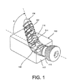
- FIG. 1 is a perspective view of an implant incorporating a flexible anchoring member according to an embodiment.
- FIG. 2 is a perspective view of a spacer member of the implant of FIG. 1 .
- FIG. 3 is a perspective view of the anchoring member of FIG. 1 .
- FIG. 4 is a side view of the implant of FIG. 1 coupled to a portion of a spine.
- FIG. 5 is a perspective view of a portion of an expandable member accompanied by an insertion instrument according to another embodiment, shown transparent and in a partially expanded configuration.
- FIG. 6 is a perspective view of a portion of the expandable member of FIG. 5 , shown transparent and in the partially expanded configuration.
- FIG. 7A is a side view partially in cross-section of a portion of the expandable member of FIG. 5 , shown in a collapsed configuration within the insertion instrument.
- FIG. 7B is a perspective view of a portion of the expandable member of FIG. 5 , shown in an expanded configuration outside of the insertion instrument.
- FIG. 8 is a perspective exploded view of a portion of the expandable member of FIG. 5 , shown in the expanded configuration and detached from the insertion instrument.
- FIG. 9 is a perspective view illustrating two expandable members of FIG. 5 disposed within a portion of a spine.
- FIG. 10 is a rear view of the two expandable members and portion of a spine of FIG. 9 .
- FIG. 11 is a side view of the two expandable members of FIG. 9 disposed within a portion of a spine.
- FIG. 12 is a perspective view of a portion of an expandable member according to another embodiment.
- FIG. 13 is a side view of a portion of a bore-forming member according to another embodiment shown in a first configuration and with the components of the bore-forming member shown transparent.
- FIG. 14 is a side view shown partially in cross-section of a portion of the bore-forming member of FIG. 13 shown in the first configuration.
- FIG. 15 is a side view shown partially in cross-section of a portion of the bore-forming member of FIG. 13 shown in a second configuration and partially transparent.
- FIG. 16 is a side view of a portion of the bore-forming member of FIG. 13 shown in the second configuration.
- FIG. 17 is a side view of a portion of the bore-forming member of FIG. 12 , shown being used within a portion of a spine, and a portion of the expandable member of FIG. 5 shown disposed within a portion of the spine.
- FIG. 18 is a flow chart illustrating a method forming a non-linear bore in an anatomical structure to receive a flexible member therein.
- the devices and methods described herein are generally directed to implants or members that can be used to support and/or stabilize anatomical structures within a body of a patient.
- the devices and methods described herein are configured to provide support to a spine or back of a patient. In other embodiments, other portions of the body of the patient can be supported by the devices described herein.
- the implants or members described herein can be flexible such that the member can be inserted or implanted within a body of a patient (e.g., an anatomical structure or structures) in a curved trajectory.
- a member described herein can be used to form or create a curved bore or passageway within an anatomical structure in which another implant can be inserted.
- a flexible cutting tool is described that can be used to form a curved bore or passageway within an anatomical structure or structure in which a flexible anchoring member or flexible fusion rod member can be inserted.
- at least a portion of the implants described herein can be inflatable.
- FIG. 1 illustrates an implant incorporating a flexible anchoring member, according to an embodiment.
- the implant comprises a spacer member 102 with a flexible anchoring member 104 incorporated therein.
- the spacer member 102 can be implanted adjacent to or within an anatomical structure.
- the spacer member 102 can be implanted into an intervertebral disc, or adjacent a vertebra of a patient.
- the spacer member 102 can be used, for example, as a support to an anatomical structure, or as a replacement for a portion of an anatomical structure.
- the spacer member 102 can be formed with a variety of different types of material used for such implants, such as, for example, medical grade plastic or metals.
- the spacer member 102 can be formed as a solid or substantially solid component. In some embodiments, the spacer member 102 can be inflatable.
- the spacer member 102 defines a curved passageway or bore 106 that includes a threaded portion 108 adjacent an opening 110 defined in a sidewall 112 of the spacer 102 .
- the threaded portion 108 extends within a larger portion of the curved passageway 106 .
- the threaded portion 108 extends along the entire passageway 106 .
- the spacer member 102 also defines an opening 114 in a top wall 116 (or any other side wall in a non-colinear trajectory) of the spacer 102 .
- the opening 110 and the opening 114 are each in fluid communication with the curved bore 106 .
- An axis A-A defined by the bore 106 at opening 114 of the flexible anchoring member 104 extends at an angle ⁇ relative to a top surface of the wall 116 of the spacer member 102 , as shown in FIG. 2 .
- the opening 114 can extend at an angle ⁇ between about 5° and less than about 90°.
- the angle ⁇ can be, for example, 35°, 40°, 45°, 50°, 60° or 65°.
- the spacer member 102 can include other openings in communication with the bore 106 , such as, an opening on a bottom wall of the spacer 102 and/or an opening on any other side wall of the spacer member 102 .
- the spacer member 102 can also include more than one curved bore.
- the flexible anchoring member 104 includes a threaded portion 118 and a head portion 120 for engaging a driving tool (not shown).
- the threaded portion 118 includes a distal portion 122 and a proximal portion 124 .
- the flexible anchoring member 104 can be formed with any biocompatible material, such as titanium, steel, and alloys thereof, as well as polymers such as PEEK and polyurethane.
- the threaded portion 118 can include a helical (e.g., single or double) wire cut pattern.
- the flexible anchoring member 104 can have a linear or substantially linear configuration as shown, for example, in FIG. 3 , or can alternatively have a zig-zag cut.
- the flexible anchoring member 104 can bend or flex to a variety of different curved configurations, such as the curved configuration shown in FIG. 1 .
- the flexible anchoring member 104 is flexible only along a portion of the threaded portion 118 , while in other embodiments, the flexible anchoring member 104 is flexible along its entire threaded portion 118 .
- the flexible anchoring member 104 can include a number of features to aid in its flexibility, such as slits that are cut along its shaft.
- the flexible anchoring member 104 can be inserted through the opening 110 of the spacer member, through the curved bore 106 and through the opening 114 of the spacer member 102 . As shown in FIG. 1 , a portion of the threaded portion 118 can extend out of the opening 114 of the spacer member 102 at the angle ⁇ relative to the wall 116 of the spacer member 102 .
- the spacer member 102 can be implanted within an anatomical structure of a patient, or adjacent an anatomical structure, such as, for example, within an intervertebral disc D, or adjacent a vertebra, as shown, for example, in FIG. 4 .
- the flexible anchoring member 104 can be inserted into the curved bore 106 of the spacer 102 and using, for example, a driver tool (not shown) can be rotated within the bore 106 such that as the distal end portion 122 of the threaded portion 118 of the flexible anchoring member 104 is moved through the opening 114 of the spacer member 102 , it can be threadably inserted into a portion of an adjacent vertebra V 1 .
- the distal end portion 122 of the threaded portion 118 can engage tissue within the vertebra V 1 to secure the flexible anchoring member 104 thereto.
- the proximal portion 124 of the threaded portion 118 of the flexible anchoring member 104 can threadably engage the threaded portion 108 within the bore 106 of the spacer member 102 to secure the flexible anchoring member 104 to the spacer member 102 .
- the curved bore 106 of the spacer member 102 and the flexibility of the flexible anchoring member 104 can allow the spacer member 102 to be secured or anchored to adjacent anatomical structures along a curved trajectory.
- the ability to curve the shaft (e.g., the threaded portion 118 ) of the flexible anchoring member 102 can provide access in locations that are typically not reachable without breaching a neighboring anatomical structure.
- such a implant 100 can be desirable where anchoring of a component such as the spacer member 102 is desired and the anchoring member is not a primary load bearing component of the implant.
- FIGS. 5-8 illustrate an expandable member or expandable member 200 accompanied by an insertion instrument 234 according to another embodiment.
- the expandable member 200 can be used as an interbody fusion rod between for example, adjacent vertebra of a patient.
- the expandable member 200 can be inserted for example, through a pedicle of a vertebra.
- the expandable member 200 includes an expandable portion 230 and is accompanied by an insertion instrument 234 .
- the expandable member includes a first portion 236 and a second portion 238 , and defines an interior region 232 , as shown, for example in FIGS. 5 and 6 ( FIGS. 5 and 6 shown transparent for illustration purposes).
- the expandable member 200 can be moved between a collapsed configuration (not shown) when disposed for example, within a lumen of a cannula, and an expanded configuration, as shown in FIGS. 7B and 8 ( FIGS. 5 and 6 illustrate the expandable member 200 in a partially collapsed configuration).
- an inflation medium can be injected into the interior region 232 to move the expandable portion 230 to its expanded configuration.
- a support member 240 (described in more detail below) can help move the expandable member 200 to its expanded configuration.
- the expandable member 200 can be formed with, for example, a flexible and/or an elastic material.
- the expandable member 200 can be formed with any biocompatible material. Among the materials that can be used include silicon, polyurethane, nylon, polycarbonate urethane and other polymers. In addition, shape memory alloys such as Nitinol, elgiloy and others can also be used.
- the insertion member 234 includes a distal end portion 246 that can be removably coupled to a proximal portion 248 of the expandable member 200 .
- the insertion member 234 can include a lumen 235 that extends between a proximal end portion (not shown) and the distal end portion 246 .
- the insertion member 234 can advantageously be used to insert the expandable member 200 into a patient's body and can also be used to inject or communicate an inflation medium, such as, for example, a curing agent, into the interior region 232 of the expandable member 200 .
- the expandable member 200 also includes a support member 240 (as mentioned above) that can be removably disposed within the interior region 232 of the expandable portion 230 , as shown in FIG. 6 .
- a distal end portion of the support member 240 includes a first portion 242 and a second portion 244 .
- the first portion 242 is configured to be at least partially disposed within the first portion 236 of the expandable portion 230
- the second portion 244 is configured to be at least partially disposed within the second portion 238 of the expandable member 200 .
- the support member 240 can also include an elongate portion (not shown) that extends to a proximal end portion (not shown) of the support member 240 .
- the support member 240 can be formed with a shape-memory material, such as, for example, Nitinol.
- a shape-memory material such as, for example, Nitinol.
- materials that can be used include silicon, polyurethane, nylon, polycarbonate urethane and other polymers.
- shape memory alloys such as elgiloy can also be used.
- the support member 240 is advantageously capable of being rigid enough to provide support for the expandable members, but also flexible enough to conform to different shapes.
- the support member 240 can have a collapsed configuration (not shown) when constrained within, for example, the lumen 235 of the insertion member 234 , and can have a biased expanded configuration when not constrained, as shown in FIG. 7B ( FIG. 6 illustrates the support member 240 in a partially expanded configuration). While in FIG. 7B , the support member 240 is illustrated as a single element, in other embodiments, the support member 240 can be composed of multiple elements (e.g., multiple Nitinol wires) to assist in expansion of the expandable member 200 in various directions.
- the support member 240 can be used in conjunction with the inflation medium to move the expandable member 200 from its collapsed configuration to its expanded configuration.
- the expandable member 200 can be coupled to the insertion member 234 , and the expandable member 200 and the insertion member 234 can collectively be inserted through a lumen 245 of a cannula 247 , as shown in FIG. 7A , to place the expandable member 200 in its collapsed configuration.
- the support member 240 (not shown in FIG. 7A ) can be disposed in a collapsed configuration with the first portion 242 and the second portion 244 of the support member 240 disposed within the interior region 232 of the expandable member 200 .
- the support member 240 With the expandable member 200 within the lumen 245 of the cannula 247 , the support member 240 will be restrained in its collapsed configuration. A distal portion of the cannula 247 can then be inserted into a bore within an anatomical structure within a body of a patient. For example, one or more bores may be preformed in the anatomical structure.
- the cannula 247 When disposed at the desired location within the anatomical structure, the cannula 247 can be moved proximally and/or the expandable member 200 can be moved distally such that the expandable member 200 is moved outside of the lumen 245 of the cannula 247 and within the anatomical structure.
- a bore can be preformed within the anatomical structure prior to inserting the expandable member 200 and the expandable member 200 can be disposed within the bore.
- the support member 240 will be unconstrained and can begin to assume its biased expanded configuration while within the interior region 232 of the expandable member 200 .
- the first portion 242 and the second portion 244 of the support member 240 will move apart from each other, as shown in FIG. 7B .
- This in turn will move the first portion 236 and the second portion 238 of the expandable member 200 away from each other.
- the first portion 236 and the second portion 238 move apart from each other, they can each self-locate within a bore defined within the anatomical structure.
- the first portion 236 and the second portion 238 can find or be forced into the bores within the anatomical structure as they are expanded.
- the support member 240 can be removed through a lumen 235 of the insertion member 234 .
- the insertion member 234 can be used to inject or communicate an inflation medium into the interior region 232 of the expandable member 200 (e.g., via the lumen 235 ).
- the inflation medium can be for example, a curing agent that can set or harden after being injected.
- the first portion 236 and the second portion 238 can continue to expand into the bores in the anatomical structure.
- the insertion member 234 can then be decoupled from the expandable member 200 (as shown in FIG. 8 ) and removed from the patient's body.
- the first portion 242 and the second portion 244 of the support member 240 can be disposed within the lumen 235 of the insertion member 234 to restrain the support member 240 in its collapsed configuration.
- the support member 240 can be moved distally such that the first portion 242 and the second portion 244 are disposed within the interior region 232 of the expandable member 200 .
- the expandable member 200 can be inserted into a patient's body without the use of a cannula 247 as described above.
- the expandable member 200 can be coupled to the insertion member 234 and the support member 240 can be disposed within the lumen 235 of the insertion member 234 , as discussed above.
- the expandable member 200 can then be inserted into an opening formed in an anatomical structure of a patient, and moved to a desired location within the anatomical structure.
- the expandable member 200 can maintain its collapsed configuration until the insertion member 234 injects an inflation medium into the expandable member 200 as described above, and/or until the first portion 242 and the second portion 244 of the support member 240 are moved out of the lumen 235 of the insertion member 234 and into the interior region 232 of the expandable member 200 , such that the support member 240 can assume its expanded configuration as discussed above.
- the support member 240 can be configured to remain within the interior region 232 of the expandable member 200 .
- the inflation medium can be injected into the interior region 232 and can surround and contact the support member 240 .
- the support member 240 can provide additional strength to the expandable member 200 after implantation of the expandable member 200 .
- the expandable member 200 may not include a support member 240 .
- the inflation medium can be used to move the expandable member to its expanded configuration.
- FIGS. 9 and 10 illustrate the expandable member 200 and a second expandable member 200 ′ disposed within a portion of a spine.
- the expandable member 200 ′ is configured the same as the expandable member 200 described above and is therefore not described in detail here.
- the expandable portions 230 and 230 ′ are each used as a fusion rod between a first vertebra V 1 , an intervertebral disc D and a second vertebra V 2 .
- the expandable portions 230 and 230 ′ can each be coupled to an insertion member 234 and 234 ′ and inserted through, for example, a pedicle of the second vertebra V 2 in a similar manner as described above.
- the insertion member 234 ′ can be configured the same as the insertion member 234 described above.
- a first bore can be preformed within the second vertebra V 2 and configured to receive the second portion 238 of the expandable members 230 .
- a second bore can be preformed within the second vertebra V 2 and configured to receive the first portion 236 .
- a bore can be preformed through the intervertebral disc D and a bore can be preformed within the first vertebra V 1 that can each be in communication with the second bore of the second vertebra V 2 and can receive a portion of the first portion 236 of the expandable member 200 .
- the second portion 238 can self-locate within the first preformed bore of the second vertebra V 2
- the first portion 236 can self-locate within the second preformed bore of the second vertebra V 2 , the preformed bore of the disc D and the preformed bore of the first vertebra V 1 .
- the insertion member 234 can be removed. The same process can be done to the expandable member 200 ′.
- FIG. 11 illustrates another example use of expandable members having expandable portions 230 and 230 ′ as described above.
- the expandable portion 230 is shown being used as fusion rod between a first vertebra V 1 and a second vertebra V 2
- the expandable portion 230 ′ is shown being used as a fusion rod between the second vertebra V 2 and a third vertebra V 3 .
- Portions of the insertion members 234 and 234 ′ are also illustrated.
- the expandable portions 230 , 230 ′ can be inserted through a pedicle of the vertebra V 1 and a pedicle of the vertebra V 2 .
- FIG. 12 is an example of an alternative embodiment of an expandable member 300 accompanied by an insertion instrument 334 .
- the expandable member 300 includes an expandable portion 330 .
- the expandable member 300 can also include a support member (not shown) as described above for expandable member 200 .
- the expandable member 300 can be configured similar to, and function the same as or similar to, the expandable member 200 and therefore, certain details are not repeated with respect to this embodiment.
- the expandable member 300 includes a first portion 336 and a second portion 338 .
- the first portion 336 includes a first textured portion 350 and the second portion 338 includes a second textured portion 352 .
- the textured portions can comprise protrusions that extend from the surface of the expandable member.
- the textured portions 350 and 352 can each be used to promote engagement between the first portion 336 and the second portion 338 and the surrounding tissue within the anatomical structure in which they are being disposed.
- the expandable member 300 can be implanted within an anatomical structure in the same manner as described above for expandable member 200 .
- FIGS. 13-16 illustrate a bore forming member 400 according to another embodiment.
- the bore forming member 400 can be used to form a bore or passageway within an anatomical structure.
- the bore forming member 400 can be used to form a curved or angled bore or passageway that can receive an implantable implant, such as the implants 200 and 300 described above.
- the bore forming member 400 includes a first elongate member 454 , a second elongate member 456 and a third elongate member 460 .
- the second elongate member 456 can be movably received within a lumen 458 defined by the first elongate member 454 .
- the third elongate member 460 can be received within a lumen 462 defined by the second elongate member 456 .
- FIG. 13 shows the first elongate member 454 and the second elongate member 456 transparent for illustration purposes.
- the second elongate member 456 can be formed such that it is flexible and can be moved between a first configuration in which the second elongate member 456 is linear or substantially linear, and a second configuration in which at least a portion of the second elongate member 456 is curved.
- first configuration in which the second elongate member 456 is linear or substantially linear
- second configuration in which at least a portion of the second elongate member 456 is curved.
- the second elongate member 456 will be restrained in a substantially straight or linear configuration and define an axis A-A as shown in FIG. 14 .
- a distal end portion 466 of the second elongate member 456 is moved outside of the lumen 458 , as shown in FIGS.
- the distal end portion 466 of the second elongate member 456 can be moved such that the distal end portion 466 is at an angle ⁇ relative to the axis A-A as described in more detail below.
- the second elongate member 456 can be formed with, for example, any biocompatible material such as stainless steel, titanium, various alloys and polymeric materials.
- the second elongate member 456 can include multiple cutting portions 464 disposed on the distal end portion 466 of the second elongate member 456 .
- the second elongate member 456 may include only one cutting portion 464 .
- the second elongate member 456 can also define multiple openings 468 that are in fluid communication with the lumen 462 of the second elongate member 456 .
- the cutting portions 464 can be used to cut (or disrupt, tear, etc.) tissue within an anatomical structure as described in more detail below.
- the openings 468 can receive pieces of tissue that are cut by the cutting portions 464 .
- the second elongate member 456 can include less or more openings 468 than shown, and in some embodiments, the second elongate member 456 does not include openings 468 .
- the third elongate member 460 can be formed with a shape-memory material, such as for example, Nitinol.
- the third elongate member 460 can be used to move the second elongate member 456 from its first configuration (e.g., substantially linear) to its second configuration (e.g., non-linear).
- the third elongate member 460 can have a biased pre-bent or curved shape.
- the third elongate member 460 will be constrained in a substantially linear configuration.
- the third elongate member 460 can be allowed to assume its biased curved shape as shown in FIG. 15 .
- the third elongate member 460 assumes its biased curved shape, because of the flexibility of the second elongate member 456 , it will in turn cause the distal end portion 466 of the second elongate member 456 to bend or curve as shown in FIGS. 15 and 16 .
- the bore forming member 400 can be used to form a non-linear bore or passageway within an anatomical structure, such as for example, a vertebra or an intervertebral disc.
- the bore forming member 400 can form a bore that has a curved trajectory.
- the bore forming member 400 can form a bore that is angled with respect to an insertion opening of the anatomical structure.
- the bore forming member 400 can be inserted into an anatomical structure through an opening that has a centerline axis.
- the bore forming member 400 can then form a bore that has a centerline axis that is at angle with respect to the centerline axis of the insertion opening into the anatomical structure.
- the bore forming member 400 can be inserted into an anatomical structure with the second elongate member 456 disposed within the lumen 458 of the first elongate member 454 .
- the second elongate member 456 can be moved distally relative to the first elongate member 454 (or the first elongate member 454 can be moved proximally relative to the second elongate member 456 ) such that the distal end portion 466 of the second elongate member 456 is moved outside of the lumen 458 of the first elongate member 454 and within the tissue of the anatomical structure.
- the second elongate member 456 can be rotated when the distal end portion 466 of the second elongate member 456 is disposed outside of the lumen 458 of the first elongate member 454 .
- the second elongate member 456 can be rotated simultaneously with the distal movement of the second elongate member 456 or after the distal movement of the second elongate member 456 .
- the distal end portion 466 of the second elongate member 456 will be slowly moving to a curved or bent configuration while rotating within the anatomical structure. This action can allow the cutting portions 464 of the second elongate member 456 to cut tissue within the anatomical structure as the second elongate member 456 moves along a curved or angled path or trajectory within the anatomical structure.
- the resulting bore or passageway formed within the anatomical structure can also be curved or angled.
- the bore forming member 400 can be used to form a non-linear (e.g., curved or angled) bore or passageway within a single anatomical structure or within multiple anatomical structures.
- the bore forming member 400 can be used to form a continuous curved or angled bore that extends between two or more anatomical structures.
- FIG. 17 illustrates the bore forming member 400 being used to form a curved bore within a vertebra V 2 and also within an adjacent intervertebral disc D 1 .
- Such a curved bore can be used to implant a implant, such as the implants described herein.
- the bore forming member 400 can preform a first bore within a vertebra V 3 and a second bore that extends within the vertebra V 3 , into the intervertebral disc D 2 and into the vertebra V 2 .
- a implant such as the expandable member 200 (as shown in FIG. 17 ) can be inserted therein as described above for expandable member 200 .
- the bore forming member 400 can also be used to form multiple bores within the same anatomical structure.
- the bore forming member 400 can be positioned in a first location within the anatomical structure to form a first curved or angled bore, and then be repositioned at a second location within the anatomical structure to form a second curved or angled bore.
- FIG. 18 illustrates a method of using a flexible member (e.g., bore forming member 400 ) to form a non-linear bore or passageway in an anatomical structure that can receive an implant (e.g., implants 200 , 300 ) within the formed bore or passageway.
- the method includes at 570 , inserting a distal end portion of a flexible member (e.g., bore forming member 400 ) into a portion of an anatomical structure within a body of a patient.
- the anatomical structure can be a portion of a spine, such as a vertebra.
- the bore forming member can include a first elongate member (e.g., 454 ) that defines a lumen between a proximal end portion and a distal end portion of the first elongate member, and a second elongate member (e.g., 456 ) movably disposable within the lumen of the first elongate member.
- the second elongate member can be flexible and include at least one cutting member disposed on an outer surface of a distal end portion of the second elongate member. The distal end portion of the second elongate member can be movable to a curved configuration when disposed outside the lumen of the first elongate member.
- tissue can be cut along a non-linear path to form a non-linear passageway within the anatomical structure by moving the second elongate member distally relative to the first elongate member and rotating the second elongate member such that the at least one cutting member on the distal end portion of the second elongate member cuts tissue within the anatomical structure.
- the flexible member can be removed from the anatomical structure.
- a flexible implant e.g., 200 , 300
- each of the various components can be formed with any biocompatible material used for such implants.
- each of the various components can be formed with one or more biocompatible plastics and/or one or more biocompatible metals, such as, for example, titanium and stainless steel.
Abstract
A spacer member is provided that is configured to be implanted adjacent an anatomical structure. The spacer member defines a curved bore, a first opening in a side wall of the spacer member and a second opening in one of a top wall and a bottom wall of the spacer member. Each of the first opening and the second opening are in fluid communication with the curved bore. A flexible anchoring member is configured to be inserted through the side opening and through the curved bore of the spacer member such that a distal end portion of the flexible anchoring member extends out of the second opening at an angle relative to the one of the top wall and the bottom wall of the spacer member.
Description
The present application is a divisional application of U.S. patent application Ser. No. 13/245,139 filed on Sep. 26, 2011, entitled “Flexible Anchoring and Fusion Devices and Methods of Using the Same”, the entire contents of which are incorporated herein by reference.
This disclosure relates generally to implants and more particularly to anchoring devices configured to be coupled to a portion of a spine and a flexible medical tool that can be used to form a curved path within a portion of a spine.
A variety of implants and implant systems are implanted within a body of a patient to provide support to a portion or portions of the patient's body. For example, some implants are implanted and coupled to backbones or portions of a spine of a patient and are configured to provide support to the spinal bone structure of the patient. Some implant systems that are configured to provide support to the spinal bone structure of a patient include support members or fusion rods that are implanted within an interior portion of the spinal bone structure, such as, within an intervertebral disc and/or within a vertebra. Some implants are configured to be secured to a spinal bone structure with, for example, an anchoring fastener, such as, an anchoring screw.
In some cases, access to implant or insert such support devices and/or anchoring devices within a body structure of a patient can be challenging. Typical linear and/or rigid support and anchoring devices are inserted along a straight path and access can be limited. It can also be difficult to avoid breaching neighboring anatomy when inserting the anchoring device. In addition, typical medical tools configured to drill or form a path or bore within a body structure to receive such support and anchoring devices are also rigid and can only form a straight or linear bore or passageway.
Accordingly, there is a need for medical support devices and anchoring devices that are flexible and can be inserted along a curved trajectory or bore within a body structure. There is also a need for medical boring or drilling devices that are flexible and can form a curved passageway or bore within a body structure that can receive a curved support device or anchoring device.
In some embodiment, an implant includes, a spacer member configured to be implanted adjacent an anatomical structure. The spacer member defines a curved bore, a first opening in a side wall of the spacer member and a second opening in one of a top wall and a bottom wall of the spacer member. Each of the first opening and the second opening are in fluid communication with the curved bore. A flexible anchoring member is configured to be inserted through the side opening and through the curved bore of the spacer member such that a distal end portion of the flexible anchoring member extends out of the second opening at an angle relative to the one of the top wall and the bottom wall of the spacer member.
In some embodiments, an implant includes an expandable fusion member configured to be inserted while in a collapsed configuration into a portion of a first vertebra of a patient. The expandable fusion member is configured to receive an inflation medium within an interior region defined by the expandable fusion member to move the expandable fusion member from the collapsed configuration to an expanded configuration while disposed within the first vertebra. When in the expanded configuration, the first portion of the expandable fusion member extends within a bore within a first portion of a vertebra, and the second portion extends within a second bore within the first vertebra.
In some embodiments, an apparatus includes a first elongate member that defines a lumen that extends between a proximal end portion and a distal end portion of the first elongate member. A second elongate member is movably disposable within the lumen of the first elongate member. The second elongate member is flexible and includes at least one cutting member disposed on an outer surface of a distal end portion of the second elongate member. The first elongate member configured to restrain the second elongate member in a substantially linear configuration when disposed within the lumen of the first elongate member, the second elongate member being movable to a curved configuration when disposed outside of the lumen of the first elongate member. A distal end portion of the first elongate member is configured to be inserted into a portion of an anatomical structure of a patient when the distal end portion of the second elongate member is disposed within the lumen of the first elongate member. The distal end portion of the second elongate member is configured to cut tissue within the portion of the anatomical structure along a non-linear path to form a non-linear passageway within the anatomical structure when the second elongate member is moved distally relative to the first elongate member such that the distal end portion of the second elongate member extends outside of the lumen of the first elongate member and is moved to its curved configuration and the second elongate member is rotated.
In some embodiments, a method includes inserting a distal end portion of an implant into a portion of an anatomical structure within a body of a patient. The implant includes a first elongate member and a second elongate member. The first elongate member defines a lumen between a proximal end portion and a distal end portion of the first elongate member. The second elongate member is movably disposable within the lumen of the first elongate member. The second elongate member is flexible and includes at least one cutting member disposed on an outer surface of a distal end portion of the second elongate member. The distal end portion of the second elongate member being movable to a curved configuration when disposed outside the lumen of the first elongate member. Tissue is cut along a non-linear path to form a non-linear passageway within the anatomical structure by moving the second elongate member distally relative to the first elongate member and rotating the second elongate member relative to the first elongate member such that the at least one cutting member on the distal end portion of the second elongate member cuts tissue within the anatomical structure
The devices and methods described herein are generally directed to implants or members that can be used to support and/or stabilize anatomical structures within a body of a patient. In some embodiments, the devices and methods described herein are configured to provide support to a spine or back of a patient. In other embodiments, other portions of the body of the patient can be supported by the devices described herein.
In some embodiments, the implants or members described herein (also referred to as “apparatus” or “device”) can be flexible such that the member can be inserted or implanted within a body of a patient (e.g., an anatomical structure or structures) in a curved trajectory. In some embodiments, a member described herein can be used to form or create a curved bore or passageway within an anatomical structure in which another implant can be inserted. For example, in some embodiments, a flexible cutting tool is described that can be used to form a curved bore or passageway within an anatomical structure or structure in which a flexible anchoring member or flexible fusion rod member can be inserted. In some embodiments, at least a portion of the implants described herein can be inflatable.
As shown, for example, in FIG. 2 , the spacer member 102 defines a curved passageway or bore 106 that includes a threaded portion 108 adjacent an opening 110 defined in a sidewall 112 of the spacer 102. In some embodiments, the threaded portion 108 extends within a larger portion of the curved passageway 106. In some embodiments, the threaded portion 108 extends along the entire passageway 106. The spacer member 102 also defines an opening 114 in a top wall 116 (or any other side wall in a non-colinear trajectory) of the spacer 102. The opening 110 and the opening 114 are each in fluid communication with the curved bore 106. An axis A-A defined by the bore 106 at opening 114 of the flexible anchoring member 104 extends at an angle θ relative to a top surface of the wall 116 of the spacer member 102, as shown in FIG. 2 . For example, the opening 114 can extend at an angle θ between about 5° and less than about 90°. In some embodiments, the angle θ can be, for example, 35°, 40°, 45°, 50°, 60° or 65°. Although not shown, alternatively or in addition to the openings 110 and 114, the spacer member 102 can include other openings in communication with the bore 106, such as, an opening on a bottom wall of the spacer 102 and/or an opening on any other side wall of the spacer member 102. The spacer member 102 can also include more than one curved bore.
The flexible anchoring member 104 includes a threaded portion 118 and a head portion 120 for engaging a driving tool (not shown). The threaded portion 118 includes a distal portion 122 and a proximal portion 124. The flexible anchoring member 104 can be formed with any biocompatible material, such as titanium, steel, and alloys thereof, as well as polymers such as PEEK and polyurethane. In some embodiments, the threaded portion 118 can include a helical (e.g., single or double) wire cut pattern. The flexible anchoring member 104 can have a linear or substantially linear configuration as shown, for example, in FIG. 3 , or can alternatively have a zig-zag cut. The flexible anchoring member 104 can bend or flex to a variety of different curved configurations, such as the curved configuration shown in FIG. 1 . In some embodiments, the flexible anchoring member 104 is flexible only along a portion of the threaded portion 118, while in other embodiments, the flexible anchoring member 104 is flexible along its entire threaded portion 118. In some embodiments, the flexible anchoring member 104 can include a number of features to aid in its flexibility, such as slits that are cut along its shaft.
The flexible anchoring member 104 can be inserted through the opening 110 of the spacer member, through the curved bore 106 and through the opening 114 of the spacer member 102. As shown in FIG. 1 , a portion of the threaded portion 118 can extend out of the opening 114 of the spacer member 102 at the angle θ relative to the wall 116 of the spacer member 102.
In use, the spacer member 102 can be implanted within an anatomical structure of a patient, or adjacent an anatomical structure, such as, for example, within an intervertebral disc D, or adjacent a vertebra, as shown, for example, in FIG. 4 . The flexible anchoring member 104 can be inserted into the curved bore 106 of the spacer 102 and using, for example, a driver tool (not shown) can be rotated within the bore 106 such that as the distal end portion 122 of the threaded portion 118 of the flexible anchoring member 104 is moved through the opening 114 of the spacer member 102, it can be threadably inserted into a portion of an adjacent vertebra V1. The distal end portion 122 of the threaded portion 118 can engage tissue within the vertebra V1 to secure the flexible anchoring member 104 thereto. The proximal portion 124 of the threaded portion 118 of the flexible anchoring member 104 can threadably engage the threaded portion 108 within the bore 106 of the spacer member 102 to secure the flexible anchoring member 104 to the spacer member 102.
Thus, the curved bore 106 of the spacer member 102 and the flexibility of the flexible anchoring member 104 can allow the spacer member 102 to be secured or anchored to adjacent anatomical structures along a curved trajectory. The ability to curve the shaft (e.g., the threaded portion 118) of the flexible anchoring member 102 can provide access in locations that are typically not reachable without breaching a neighboring anatomical structure. In some embodiments, such a implant 100 can be desirable where anchoring of a component such as the spacer member 102 is desired and the anchoring member is not a primary load bearing component of the implant.
The insertion member 234 includes a distal end portion 246 that can be removably coupled to a proximal portion 248 of the expandable member 200. The insertion member 234 can include a lumen 235 that extends between a proximal end portion (not shown) and the distal end portion 246. The insertion member 234 can advantageously be used to insert the expandable member 200 into a patient's body and can also be used to inject or communicate an inflation medium, such as, for example, a curing agent, into the interior region 232 of the expandable member 200.
The expandable member 200 also includes a support member 240 (as mentioned above) that can be removably disposed within the interior region 232 of the expandable portion 230, as shown in FIG. 6 . A distal end portion of the support member 240 includes a first portion 242 and a second portion 244. The first portion 242 is configured to be at least partially disposed within the first portion 236 of the expandable portion 230, and the second portion 244 is configured to be at least partially disposed within the second portion 238 of the expandable member 200. The support member 240 can also include an elongate portion (not shown) that extends to a proximal end portion (not shown) of the support member 240. In some embodiments, the support member 240 can be formed with a shape-memory material, such as, for example, Nitinol. Among the materials that can be used include silicon, polyurethane, nylon, polycarbonate urethane and other polymers. In addition, other shape memory alloys such as elgiloy can also be used.
The support member 240 is advantageously capable of being rigid enough to provide support for the expandable members, but also flexible enough to conform to different shapes. The support member 240 can have a collapsed configuration (not shown) when constrained within, for example, the lumen 235 of the insertion member 234, and can have a biased expanded configuration when not constrained, as shown in FIG. 7B (FIG. 6 illustrates the support member 240 in a partially expanded configuration). While in FIG. 7B , the support member 240 is illustrated as a single element, in other embodiments, the support member 240 can be composed of multiple elements (e.g., multiple Nitinol wires) to assist in expansion of the expandable member 200 in various directions.
The support member 240 can be used in conjunction with the inflation medium to move the expandable member 200 from its collapsed configuration to its expanded configuration. For example, the expandable member 200 can be coupled to the insertion member 234, and the expandable member 200 and the insertion member 234 can collectively be inserted through a lumen 245 of a cannula 247, as shown in FIG. 7A , to place the expandable member 200 in its collapsed configuration. In such an embodiment, the support member 240 (not shown in FIG. 7A ) can be disposed in a collapsed configuration with the first portion 242 and the second portion 244 of the support member 240 disposed within the interior region 232 of the expandable member 200. With the expandable member 200 within the lumen 245 of the cannula 247, the support member 240 will be restrained in its collapsed configuration. A distal portion of the cannula 247 can then be inserted into a bore within an anatomical structure within a body of a patient. For example, one or more bores may be preformed in the anatomical structure.
When disposed at the desired location within the anatomical structure, the cannula 247 can be moved proximally and/or the expandable member 200 can be moved distally such that the expandable member 200 is moved outside of the lumen 245 of the cannula 247 and within the anatomical structure. For example, as discussed above, a bore can be preformed within the anatomical structure prior to inserting the expandable member 200 and the expandable member 200 can be disposed within the bore. At the same time, the support member 240 will be unconstrained and can begin to assume its biased expanded configuration while within the interior region 232 of the expandable member 200.
As the support member 240 is moved to its expanded configuration, the first portion 242 and the second portion 244 of the support member 240 will move apart from each other, as shown in FIG. 7B . This in turn will move the first portion 236 and the second portion 238 of the expandable member 200 away from each other. As the first portion 236 and the second portion 238 move apart from each other, they can each self-locate within a bore defined within the anatomical structure. In other words, as the expandable member 200 is expanded, the first portion 236 and the second portion 238 can find or be forced into the bores within the anatomical structure as they are expanded. After the first and second portions 236 and 238 are at least partially disposed within the bores in the anatomical structure, the support member 240 can be removed through a lumen 235 of the insertion member 234.
In some embodiments, the insertion member 234 can be used to inject or communicate an inflation medium into the interior region 232 of the expandable member 200 (e.g., via the lumen 235). The inflation medium can be for example, a curing agent that can set or harden after being injected. As the inflation medium is being injected into the interior region 232, the first portion 236 and the second portion 238 can continue to expand into the bores in the anatomical structure. When the expandable member 200 has been sufficiently expanded, the insertion member 234 can then be decoupled from the expandable member 200 (as shown in FIG. 8 ) and removed from the patient's body.
In some embodiments, the first portion 242 and the second portion 244 of the support member 240 can be disposed within the lumen 235 of the insertion member 234 to restrain the support member 240 in its collapsed configuration. When the expandable member 200 is disposed at the desired location within the anatomical structure, the support member 240 can be moved distally such that the first portion 242 and the second portion 244 are disposed within the interior region 232 of the expandable member 200.
In some embodiments, the expandable member 200 can be inserted into a patient's body without the use of a cannula 247 as described above. For example, the expandable member 200 can be coupled to the insertion member 234 and the support member 240 can be disposed within the lumen 235 of the insertion member 234, as discussed above. The expandable member 200 can then be inserted into an opening formed in an anatomical structure of a patient, and moved to a desired location within the anatomical structure. In such an embodiment, the expandable member 200 can maintain its collapsed configuration until the insertion member 234 injects an inflation medium into the expandable member 200 as described above, and/or until the first portion 242 and the second portion 244 of the support member 240 are moved out of the lumen 235 of the insertion member 234 and into the interior region 232 of the expandable member 200, such that the support member 240 can assume its expanded configuration as discussed above.
In some embodiments, the support member 240 can be configured to remain within the interior region 232 of the expandable member 200. In such an embodiment, the inflation medium can be injected into the interior region 232 and can surround and contact the support member 240. The support member 240 can provide additional strength to the expandable member 200 after implantation of the expandable member 200.
In some embodiments, the expandable member 200 may not include a support member 240. In such an embodiment, the inflation medium can be used to move the expandable member to its expanded configuration.
A first bore can be preformed within the second vertebra V2 and configured to receive the second portion 238 of the expandable members 230. A second bore can be preformed within the second vertebra V2 and configured to receive the first portion 236. In addition, a bore can be preformed through the intervertebral disc D and a bore can be preformed within the first vertebra V1 that can each be in communication with the second bore of the second vertebra V2 and can receive a portion of the first portion 236 of the expandable member 200. Thus, as the expandable member 200 is moved to its expanded configuration as described previously (e.g., via the support member and/or the inflation medium), the second portion 238 can self-locate within the first preformed bore of the second vertebra V2, and the first portion 236 can self-locate within the second preformed bore of the second vertebra V2, the preformed bore of the disc D and the preformed bore of the first vertebra V1. After the insertion member 234 has injected the inflation medium into the interior region of the expandable member 200, the insertion member 234 can be removed. The same process can be done to the expandable member 200′.
The expandable member 300 includes a first portion 336 and a second portion 338. In this embodiment, the first portion 336 includes a first textured portion 350 and the second portion 338 includes a second textured portion 352. In some embodiments, the textured portions can comprise protrusions that extend from the surface of the expandable member. The textured portions 350 and 352 can each be used to promote engagement between the first portion 336 and the second portion 338 and the surrounding tissue within the anatomical structure in which they are being disposed. The expandable member 300 can be implanted within an anatomical structure in the same manner as described above for expandable member 200.
As shown, for example, in FIGS. 13 and 14 , the second elongate member 456 can be movably received within a lumen 458 defined by the first elongate member 454. The third elongate member 460 can be received within a lumen 462 defined by the second elongate member 456. FIG. 13 shows the first elongate member 454 and the second elongate member 456 transparent for illustration purposes.
The second elongate member 456 can be formed such that it is flexible and can be moved between a first configuration in which the second elongate member 456 is linear or substantially linear, and a second configuration in which at least a portion of the second elongate member 456 is curved. For example, when the second elongate member 456 is disposed within the lumen 458 of the first elongate member 454, as shown in FIGS. 13 and 14 , the second elongate member 456 will be restrained in a substantially straight or linear configuration and define an axis A-A as shown in FIG. 14 . When a distal end portion 466 of the second elongate member 456 is moved outside of the lumen 458, as shown in FIGS. 15 and 16 , the distal end portion 466 of the second elongate member 456 can be moved such that the distal end portion 466 is at an angle θ relative to the axis A-A as described in more detail below. The second elongate member 456 can be formed with, for example, any biocompatible material such as stainless steel, titanium, various alloys and polymeric materials.
The second elongate member 456 can include multiple cutting portions 464 disposed on the distal end portion 466 of the second elongate member 456. In some embodiments, the second elongate member 456 may include only one cutting portion 464. In some embodiments, the second elongate member 456 can also define multiple openings 468 that are in fluid communication with the lumen 462 of the second elongate member 456. The cutting portions 464 can be used to cut (or disrupt, tear, etc.) tissue within an anatomical structure as described in more detail below. In some embodiments, the openings 468 can receive pieces of tissue that are cut by the cutting portions 464. In some embodiments, the second elongate member 456 can include less or more openings 468 than shown, and in some embodiments, the second elongate member 456 does not include openings 468.
The third elongate member 460 can be formed with a shape-memory material, such as for example, Nitinol. The third elongate member 460 can be used to move the second elongate member 456 from its first configuration (e.g., substantially linear) to its second configuration (e.g., non-linear). For example, the third elongate member 460 can have a biased pre-bent or curved shape. When disposed within the lumen 462 of the second elongate member 456 and when the second elongate member 456 is disposed with the lumen 458 of the first elongate member 454 (as shown, e.g., in FIGS. 13 and 14 ), the third elongate member 460 will be constrained in a substantially linear configuration. When the second elongate member 456 is moved out of the lumen 458 of the first elongate member 454, the third elongate member 460 can be allowed to assume its biased curved shape as shown in FIG. 15 . As the third elongate member 460 assumes its biased curved shape, because of the flexibility of the second elongate member 456, it will in turn cause the distal end portion 466 of the second elongate member 456 to bend or curve as shown in FIGS. 15 and 16 .
As discussed above, the bore forming member 400 can be used to form a non-linear bore or passageway within an anatomical structure, such as for example, a vertebra or an intervertebral disc. For example, in some embodiments, the bore forming member 400 can form a bore that has a curved trajectory. In some embodiments, the bore forming member 400 can form a bore that is angled with respect to an insertion opening of the anatomical structure. For example, the bore forming member 400 can be inserted into an anatomical structure through an opening that has a centerline axis. The bore forming member 400 can then form a bore that has a centerline axis that is at angle with respect to the centerline axis of the insertion opening into the anatomical structure.
In use, the bore forming member 400 can be inserted into an anatomical structure with the second elongate member 456 disposed within the lumen 458 of the first elongate member 454. When a distal end 470 of the first elongate member 454 is disposed at a desired location within the anatomical structure, the second elongate member 456 can be moved distally relative to the first elongate member 454 (or the first elongate member 454 can be moved proximally relative to the second elongate member 456) such that the distal end portion 466 of the second elongate member 456 is moved outside of the lumen 458 of the first elongate member 454 and within the tissue of the anatomical structure. The second elongate member 456 can be rotated when the distal end portion 466 of the second elongate member 456 is disposed outside of the lumen 458 of the first elongate member 454. The second elongate member 456 can be rotated simultaneously with the distal movement of the second elongate member 456 or after the distal movement of the second elongate member 456. As the distal end portion 466 of the second elongate member 456 is being moved outside of the lumen 458 it will also be moved to a curved or bent shape as the third elongate member 460 (disposed within the second elongate member 456) is allowed to assume its biased curved shape. Thus, the distal end portion 466 of the second elongate member 456 will be slowly moving to a curved or bent configuration while rotating within the anatomical structure. This action can allow the cutting portions 464 of the second elongate member 456 to cut tissue within the anatomical structure as the second elongate member 456 moves along a curved or angled path or trajectory within the anatomical structure. The resulting bore or passageway formed within the anatomical structure can also be curved or angled.
The bore forming member 400 can be used to form a non-linear (e.g., curved or angled) bore or passageway within a single anatomical structure or within multiple anatomical structures. For example, the bore forming member 400 can be used to form a continuous curved or angled bore that extends between two or more anatomical structures. In one example, FIG. 17 illustrates the bore forming member 400 being used to form a curved bore within a vertebra V2 and also within an adjacent intervertebral disc D1. Such a curved bore can be used to implant a implant, such as the implants described herein. For example, the bore forming member 400 can preform a first bore within a vertebra V3 and a second bore that extends within the vertebra V3, into the intervertebral disc D2 and into the vertebra V2. A implant, such as the expandable member 200 (as shown in FIG. 17 ) can be inserted therein as described above for expandable member 200.
The bore forming member 400 can also be used to form multiple bores within the same anatomical structure. For example, the bore forming member 400 can be positioned in a first location within the anatomical structure to form a first curved or angled bore, and then be repositioned at a second location within the anatomical structure to form a second curved or angled bore.
The various components of the members or implants (e.g., 100, 200, 300, 400) described herein can be formed with any biocompatible material used for such implants. For example, each of the various components can be formed with one or more biocompatible plastics and/or one or more biocompatible metals, such as, for example, titanium and stainless steel.
While certain features of the described implementations have been illustrated as described herein, many modifications, substitutions, changes and equivalents will now occur to those skilled in the art. It is, therefore, to be understood that the appended claims are intended to cover all such modifications and changes as fall within the scope of the embodiments. It should be understood that they have been presented by way of example only, not limitation, and various changes in form and details may be made. Any portion of the apparatus and/or methods described herein may be combined in any combination, except mutually exclusive combinations. The embodiments described herein can include various combinations and/or sub-combinations of the functions, components and/or features of the different embodiments described.
Claims (6)
1. A medical device, comprising:
an expandable fusion member configured to be inserted while in a collapsed configuration into a portion of a vertebra of a patient, the expandable fusion member having a first portion and a second portion and defining an interior region configured to receive an inflation medium to move the expandable fusion member from the collapsed configuration to an expanded configuration while disposed within the vertebra,
when in the expanded configuration, the first portion of the expandable fusion member extends within a first bore within a portion of the vertebra, and the second portion extends within a second bore within a portion of a first vertebra,
an elongate member removably disposable within the interior region of the fusion member, the elongate member being formed with a shape-memory material and having a collapsed configuration when inserted into the interior region of the expandable fusion member and being movable to an expanded configuration when the expandable fusion member is moved to its expanded configuration, the elongate member being biased to its expanded configuration.
2. The medical device of claim 1 , wherein the vertebra is a first vertebra, the first portion of the expandable fusion member is configured to self-locate within the first bore in the first vertebra, the second portion of the expandable fusion member is configured to self-locate within the second bore in the first vertebra, a bore in an intervertebral disc and into a bore in a second vertebra when moved to its expanded configuration.
3. The medical device of claim 1 , wherein the first portion of the expandable fusion member includes a textured portion configured to promote engagement between the first portion of the expandable fusion member and a portion of tissue within the vertebra.
4. The medical device of claim 1 , the elongate member has a first portion and a second portion, the first portion of the elongate member configured to be disposed within the portion of the interior region associated with the first portion of the expandable fusion member, the second portion of the elongate member configured to be disposed within the portion of the interior region associated with the second portion of the expandable fusion member.
5. The medical device of claim 1 , further comprising:
an insertion tool configured to be removably coupled to the expandable fusion member, the insertion tool configured to inject the inflation medium into the interior region of the expandable fusion member.
6. The medical device of claim 1 , wherein the inflation medium is a curing agent.
Priority Applications (3)
| Application Number | Priority Date | Filing Date | Title |
|---|---|---|---|
| US14/967,588 US9814591B2 (en) | 2011-09-26 | 2015-12-14 | Flexible anchoring and fusion devices and methods of using the same |
| US15/784,658 US11419732B2 (en) | 2011-09-26 | 2017-10-16 | Flexible anchoring and fusion devices and methods of using the same |
| US17/869,134 US20220354661A1 (en) | 2011-09-26 | 2022-07-20 | Flexible anchoring and fusion devices and methods of using the same |
Applications Claiming Priority (2)
| Application Number | Priority Date | Filing Date | Title |
|---|---|---|---|
| US13/245,139 US9241806B2 (en) | 2011-09-26 | 2011-09-26 | Flexible anchoring and fusion devices and methods of using the same |
| US14/967,588 US9814591B2 (en) | 2011-09-26 | 2015-12-14 | Flexible anchoring and fusion devices and methods of using the same |
Related Parent Applications (1)
| Application Number | Title | Priority Date | Filing Date |
|---|---|---|---|
| US13/245,139 Division US9241806B2 (en) | 2011-09-26 | 2011-09-26 | Flexible anchoring and fusion devices and methods of using the same |
Related Child Applications (1)
| Application Number | Title | Priority Date | Filing Date |
|---|---|---|---|
| US15/784,658 Continuation US11419732B2 (en) | 2011-09-26 | 2017-10-16 | Flexible anchoring and fusion devices and methods of using the same |
Publications (2)
| Publication Number | Publication Date |
|---|---|
| US20160106546A1 US20160106546A1 (en) | 2016-04-21 |
| US9814591B2 true US9814591B2 (en) | 2017-11-14 |
Family
ID=47912111
Family Applications (4)
| Application Number | Title | Priority Date | Filing Date |
|---|---|---|---|
| US13/245,139 Active 2032-02-22 US9241806B2 (en) | 2011-09-26 | 2011-09-26 | Flexible anchoring and fusion devices and methods of using the same |
| US14/967,588 Active 2031-10-30 US9814591B2 (en) | 2011-09-26 | 2015-12-14 | Flexible anchoring and fusion devices and methods of using the same |
| US15/784,658 Active 2032-05-16 US11419732B2 (en) | 2011-09-26 | 2017-10-16 | Flexible anchoring and fusion devices and methods of using the same |
| US17/869,134 Pending US20220354661A1 (en) | 2011-09-26 | 2022-07-20 | Flexible anchoring and fusion devices and methods of using the same |
Family Applications Before (1)
| Application Number | Title | Priority Date | Filing Date |
|---|---|---|---|
| US13/245,139 Active 2032-02-22 US9241806B2 (en) | 2011-09-26 | 2011-09-26 | Flexible anchoring and fusion devices and methods of using the same |
Family Applications After (2)
| Application Number | Title | Priority Date | Filing Date |
|---|---|---|---|
| US15/784,658 Active 2032-05-16 US11419732B2 (en) | 2011-09-26 | 2017-10-16 | Flexible anchoring and fusion devices and methods of using the same |
| US17/869,134 Pending US20220354661A1 (en) | 2011-09-26 | 2022-07-20 | Flexible anchoring and fusion devices and methods of using the same |
Country Status (1)
| Country | Link |
|---|---|
| US (4) | US9241806B2 (en) |
Families Citing this family (31)
| Publication number | Priority date | Publication date | Assignee | Title |
|---|---|---|---|---|
| US20050267481A1 (en) | 2003-10-17 | 2005-12-01 | Allen Carl | Systems, devices and apparatuses for bony fixation and disk repair and replacement and methods related thereto |
| WO2007079242A2 (en) | 2005-12-29 | 2007-07-12 | Highgate Orthopedics, Inc. | Devices and methods for bony fixation and disk repair and replaceme |
| US20090088789A1 (en) * | 2007-09-28 | 2009-04-02 | O'neil Michael J | Balloon With Shape Control For Spinal Procedures |
| US8333804B1 (en) * | 2008-03-27 | 2012-12-18 | Spinelogik, Inc. | Intervertebral fusion device and method of use |
| KR20140010427A (en) * | 2011-03-08 | 2014-01-24 | 신세스 게엠바하 | Flexible helical fixation device |
| WO2012129119A2 (en) * | 2011-03-18 | 2012-09-27 | Raed M. Ali, M.D., Inc. | Transpedicular access to intervertebral spaces and related spinal fusion systems and methods |
| US9265620B2 (en) * | 2011-03-18 | 2016-02-23 | Raed M. Ali, M.D., Inc. | Devices and methods for transpedicular stabilization of the spine |
| US9750616B2 (en) | 2012-02-17 | 2017-09-05 | Spinal Elements, Inc. | Interbody fusion device |
| US8663332B1 (en) | 2012-12-13 | 2014-03-04 | Ouroboros Medical, Inc. | Bone graft distribution system |
| US10687962B2 (en) | 2013-03-14 | 2020-06-23 | Raed M. Ali, M.D., Inc. | Interbody fusion devices, systems and methods |
| JP6836899B2 (en) | 2013-03-14 | 2021-03-03 | ラエド エム.アリ,エム.ディー.,インク. | Lateral interbody fusion devices, systems, and methods |
| US9186259B2 (en) | 2013-09-09 | 2015-11-17 | Ouroboros Medical, Inc. | Expandable trials |
| US9060876B1 (en) | 2015-01-20 | 2015-06-23 | Ouroboros Medical, Inc. | Stabilized intervertebral scaffolding systems |
| US10342678B2 (en) | 2015-02-02 | 2019-07-09 | Spinal Elements, Inc. | Interbody implant inserter |
| US20160296342A1 (en) * | 2015-04-08 | 2016-10-13 | K2M, Inc. | Flexible spinal fixation device |
| US10154863B2 (en) * | 2015-07-13 | 2018-12-18 | IntraFuse, LLC | Flexible bone screw |
| US10485595B2 (en) * | 2015-07-13 | 2019-11-26 | IntraFuse, LLC | Flexible bone screw |
| US10034699B2 (en) * | 2016-01-14 | 2018-07-31 | DePuy Synthes Products, Inc. | Stand-alone fusion implant secured by in-line fixation |
| IL261289B2 (en) | 2016-02-26 | 2023-04-01 | Activortho Inc | Active compression apparatus, methods of assembly and methods of use |
| US11224467B2 (en) | 2016-02-26 | 2022-01-18 | Activortho, Inc. | Active compression apparatus, methods of assembly and methods of use |
| US9883953B1 (en) | 2016-09-21 | 2018-02-06 | Integrity Implants Inc. | Stabilized laterovertically-expanding fusion cage systems with tensioner |
| DE102016011947A1 (en) * | 2016-10-05 | 2018-04-05 | Bluewater Medical GmbH | Screw with a head part, a threaded part and a connecting part |
| FR3058045A1 (en) * | 2016-11-03 | 2018-05-04 | Clariance | INFLATABLE NUCLEIC IMPLANT |
| JP7085554B2 (en) | 2017-01-10 | 2022-06-16 | インテグリティ インプランツ インコーポレイテッド | Deployable intervertebral fusion device |
| WO2019023251A1 (en) | 2017-07-24 | 2019-01-31 | Integrity Implants, Inc. | Surgical implant and related methods |
| EP3720376A4 (en) * | 2017-12-04 | 2021-08-04 | Activortho, Inc. | Active compression apparatus, methods of assembly and methods of use |
| US11285018B2 (en) | 2018-03-01 | 2022-03-29 | Integrity Implants Inc. | Expandable fusion device with independent expansion systems |
| US11103360B2 (en) | 2019-03-19 | 2021-08-31 | Robert Woodruff | Spinal fusion cage and method of operation |
| WO2020227352A1 (en) | 2019-05-07 | 2020-11-12 | Spinal Elements, Inc. | Cervical plate and inserter |
| US11877934B2 (en) * | 2020-04-07 | 2024-01-23 | Globus Medical, Inc. | Pedicle-based intradiscal fixation devices and methods |
| US11160589B1 (en) * | 2020-09-21 | 2021-11-02 | Randall F. Lee | System and method for joining boney structures |
Citations (41)
| Publication number | Priority date | Publication date | Assignee | Title |
|---|---|---|---|---|
| US5549679A (en) | 1994-05-20 | 1996-08-27 | Kuslich; Stephen D. | Expandable fabric implant for stabilizing the spinal motion segment |
| US5954722A (en) | 1997-07-29 | 1999-09-21 | Depuy Acromed, Inc. | Polyaxial locking plate |
| US6053922A (en) | 1995-07-18 | 2000-04-25 | Krause; William R. | Flexible shaft |
| US6206881B1 (en) | 1995-09-06 | 2001-03-27 | Synthes (Usa) | Bone plate |
| US6447546B1 (en) | 2000-08-11 | 2002-09-10 | Dale G. Bramlet | Apparatus and method for fusing opposing spinal vertebrae |
| US6629998B1 (en) | 2000-08-23 | 2003-10-07 | Chih-I Lin | Intervertebral retrieval device |
| US20040073218A1 (en) | 2002-10-15 | 2004-04-15 | The University Of North Carolina At Chapel Hill | Multi-angular fastening apparatus and method for surgical bone screw/plate systems |
| US6730061B1 (en) * | 1997-07-30 | 2004-05-04 | Alfred Cuschieri | Multiple hypodermic needle arrangement |
| US20040193162A1 (en) | 2003-02-03 | 2004-09-30 | Bramlet Dale G. | Femoral neck compression screw system with ortho-biologic material delivery capability |
| US20050070904A1 (en) | 2003-09-29 | 2005-03-31 | Darin Gerlach | Bone plates and bone plate assemblies |
| US20060085075A1 (en) * | 2004-10-04 | 2006-04-20 | Archus Orthopedics, Inc. | Polymeric joint complex and methods of use |
| US7077864B2 (en) | 2002-02-12 | 2006-07-18 | Cross Medical Products, Inc. | Vertebral interbody cage with translatable locking screw |
| US20060241593A1 (en) | 2005-04-08 | 2006-10-26 | Sdgi Holdings, Inc. | Multi-piece vertebral attachment device |
| US20060253198A1 (en) * | 2005-05-03 | 2006-11-09 | Disc Dynamics, Inc. | Multi-lumen mold for intervertebral prosthesis and method of using same |
| US20070083205A1 (en) * | 2005-09-26 | 2007-04-12 | Mohamed Attawia | Tissue augmentation, stabilization and regeneration Technique |
| US20070225721A1 (en) * | 2000-03-07 | 2007-09-27 | Zimmer Technology, Inc. | Method and apparatus for reducing femoral fractures |
| US20090105832A1 (en) | 2007-06-08 | 2009-04-23 | Ldr Medical | Intersomatic cage, intervertebral prosthesis, anchoring device and implantation instruments |
| US20090118771A1 (en) | 2007-04-11 | 2009-05-07 | Eduardo Gonzalez-Hernandez | Curved assembly for reattachment of fragmented bone segments |
| US7534268B2 (en) | 2006-01-13 | 2009-05-19 | Zimmer Spine, Inc. | Devices and methods for disc replacement |
| US20090164016A1 (en) * | 2007-12-19 | 2009-06-25 | Bassem Georgy | Device and method for orthopedic fracture fixation |
| US7744630B2 (en) | 2005-11-15 | 2010-06-29 | Zimmer Spine, Inc. | Facet repair and stabilization |
| US20100292695A1 (en) | 2009-05-15 | 2010-11-18 | Zimmer, Inc. | Threaded, flexible implant and method for threading a curved hole |
| US20100312345A1 (en) | 2009-06-04 | 2010-12-09 | Duffield William E | Intervertebral fusion implant |
| US20110015682A1 (en) | 2009-07-15 | 2011-01-20 | Orthohelix Surgical Designs, Inc. | Variable axis locking mechanism for use in orthopedic implants |
| US7892261B2 (en) | 1998-08-20 | 2011-02-22 | P Tech, Llc | Spinal implant and methods for changing spatial relationships between vertebrae |
| US7922720B2 (en) * | 2005-03-31 | 2011-04-12 | Zimmer Technology, Inc. | Orthopaedic cutting instrument and method |
| US20110106157A1 (en) | 2009-10-30 | 2011-05-05 | Warsaw Orthropedic, Inc. | Self-Locking Interference Bone Screw for use with Spinal Implant |
| US20110144703A1 (en) | 2009-02-24 | 2011-06-16 | Krause William R | Flexible Screw |
| US20110153022A1 (en) * | 2008-05-30 | 2011-06-23 | Synthes Usa, Llc | Balloon-assisted annulus repair |
| US20110178599A1 (en) * | 2009-09-17 | 2011-07-21 | Brett Darrell C | Intervertebral implant having extendable bone fixation members |
| US20110230971A1 (en) | 2009-04-15 | 2011-09-22 | Synthes Usa, Llc | Arcuate fixation member |
| US20110282387A1 (en) | 2010-05-12 | 2011-11-17 | Sean Suh | Distraction Screw |
| US20120078373A1 (en) | 2010-09-23 | 2012-03-29 | Thomas Gamache | Stand alone intervertebral fusion device |
| US20120232599A1 (en) | 2011-03-10 | 2012-09-13 | Jared Schoenly | Awl screw fixation members and related systems |
| US8313528B1 (en) | 2008-03-27 | 2012-11-20 | Spinelogik, Inc. | Intervertebral fusion device and method of use |
| US20130023876A1 (en) | 2011-07-19 | 2013-01-24 | Illuminoss Medical, Inc. | Combination Photodynamic Devices |
| US20130150968A1 (en) | 2009-12-31 | 2013-06-13 | Ldr Medical | Anchoring Device and System for an Intervertebral Implant, Intervertebral Implant and Implantation Instrument |
| US20130190874A1 (en) * | 2012-01-23 | 2013-07-25 | Paul A. Glazer | Orthopedic implants with flexible screws |
| US8523945B1 (en) | 2008-03-27 | 2013-09-03 | Spinelogik, Inc. | Method and apparatus for affixing a fusion member to vertebral bodies |
| US20130245767A1 (en) | 2012-03-19 | 2013-09-19 | Amicus Design Group, Llc | Interbody vertebral prosthetic and orthopedic fusion device with self-deploying anchors |
| US8545563B2 (en) * | 2011-02-02 | 2013-10-01 | DePuy Synthes Product, LLC | Intervertebral implant having extendable bone fixation members |
Family Cites Families (14)
| Publication number | Priority date | Publication date | Assignee | Title |
|---|---|---|---|---|
| US4601705A (en) * | 1983-10-31 | 1986-07-22 | Mccoy William C | Steerable and aimable catheter |
| US6746451B2 (en) * | 2001-06-01 | 2004-06-08 | Lance M. Middleton | Tissue cavitation device and method |
| JP4808961B2 (en) * | 2002-06-04 | 2011-11-02 | オフィス オブ テクノロジー ライセンシング スタンフォード ユニバーシティ | Device for rapidly aspirating and collecting body tissue from an encapsulated body space |
| AU2003230740B2 (en) * | 2002-11-08 | 2008-10-09 | Warsaw Orthopedic, Inc. | Transpedicular intervertebral disk access methods and devices |
| US6875219B2 (en) * | 2003-02-14 | 2005-04-05 | Yves P. Arramon | Bone access system |
| CA2560222A1 (en) * | 2004-06-22 | 2006-01-05 | Jeffrey E. Yeung | Disc shunt for treating back pain |
| US20060195091A1 (en) * | 2005-02-15 | 2006-08-31 | Mcgraw J K | Percutaneous spinal stabilization device and method |
| US9962168B2 (en) * | 2005-12-20 | 2018-05-08 | CroJor, LLC | Method and apparatus for performing minimally invasive arthroscopic procedures |
| US8926613B2 (en) * | 2011-03-25 | 2015-01-06 | Biomet Sports Medicine, Llc | Method and apparatus for forming a bone hole |
| US20080051793A1 (en) * | 2006-08-04 | 2008-02-28 | David Erickson | Drill-tap tool |
| US8137352B2 (en) * | 2006-10-16 | 2012-03-20 | Depuy Spine, Inc. | Expandable intervertebral tool system and method |
| US9272083B2 (en) * | 2009-05-29 | 2016-03-01 | Endocellutions, Inc. | Apparatus and methods for aspirating and separating components of different densities from a physiological fluid containing cells |
| US20120277582A1 (en) * | 2011-04-26 | 2012-11-01 | Kyphon Sarl | Devices and methods for osteolytic lesion assessment using a steerable catheter |
| US20140012261A1 (en) * | 2012-07-09 | 2014-01-09 | Henry Nita | Ultrasound Enhanced Selective Tissue Removal Method and Apparatus |
-
2011
- 2011-09-26 US US13/245,139 patent/US9241806B2/en active Active
-
2015
- 2015-12-14 US US14/967,588 patent/US9814591B2/en active Active
-
2017
- 2017-10-16 US US15/784,658 patent/US11419732B2/en active Active
-
2022
- 2022-07-20 US US17/869,134 patent/US20220354661A1/en active Pending
Patent Citations (42)
| Publication number | Priority date | Publication date | Assignee | Title |
|---|---|---|---|---|
| US5549679A (en) | 1994-05-20 | 1996-08-27 | Kuslich; Stephen D. | Expandable fabric implant for stabilizing the spinal motion segment |
| US6053922A (en) | 1995-07-18 | 2000-04-25 | Krause; William R. | Flexible shaft |
| US6206881B1 (en) | 1995-09-06 | 2001-03-27 | Synthes (Usa) | Bone plate |
| US5954722A (en) | 1997-07-29 | 1999-09-21 | Depuy Acromed, Inc. | Polyaxial locking plate |
| US6730061B1 (en) * | 1997-07-30 | 2004-05-04 | Alfred Cuschieri | Multiple hypodermic needle arrangement |
| US7892261B2 (en) | 1998-08-20 | 2011-02-22 | P Tech, Llc | Spinal implant and methods for changing spatial relationships between vertebrae |
| US20070225721A1 (en) * | 2000-03-07 | 2007-09-27 | Zimmer Technology, Inc. | Method and apparatus for reducing femoral fractures |
| US6447546B1 (en) | 2000-08-11 | 2002-09-10 | Dale G. Bramlet | Apparatus and method for fusing opposing spinal vertebrae |
| US6629998B1 (en) | 2000-08-23 | 2003-10-07 | Chih-I Lin | Intervertebral retrieval device |
| US7077864B2 (en) | 2002-02-12 | 2006-07-18 | Cross Medical Products, Inc. | Vertebral interbody cage with translatable locking screw |
| US20040073218A1 (en) | 2002-10-15 | 2004-04-15 | The University Of North Carolina At Chapel Hill | Multi-angular fastening apparatus and method for surgical bone screw/plate systems |
| US20040193162A1 (en) | 2003-02-03 | 2004-09-30 | Bramlet Dale G. | Femoral neck compression screw system with ortho-biologic material delivery capability |
| US20050070904A1 (en) | 2003-09-29 | 2005-03-31 | Darin Gerlach | Bone plates and bone plate assemblies |
| US20060085075A1 (en) * | 2004-10-04 | 2006-04-20 | Archus Orthopedics, Inc. | Polymeric joint complex and methods of use |
| US7922720B2 (en) * | 2005-03-31 | 2011-04-12 | Zimmer Technology, Inc. | Orthopaedic cutting instrument and method |
| US20060241593A1 (en) | 2005-04-08 | 2006-10-26 | Sdgi Holdings, Inc. | Multi-piece vertebral attachment device |
| US20060253198A1 (en) * | 2005-05-03 | 2006-11-09 | Disc Dynamics, Inc. | Multi-lumen mold for intervertebral prosthesis and method of using same |
| US20070083205A1 (en) * | 2005-09-26 | 2007-04-12 | Mohamed Attawia | Tissue augmentation, stabilization and regeneration Technique |
| US7744630B2 (en) | 2005-11-15 | 2010-06-29 | Zimmer Spine, Inc. | Facet repair and stabilization |
| US7534268B2 (en) | 2006-01-13 | 2009-05-19 | Zimmer Spine, Inc. | Devices and methods for disc replacement |
| US20090118771A1 (en) | 2007-04-11 | 2009-05-07 | Eduardo Gonzalez-Hernandez | Curved assembly for reattachment of fragmented bone segments |
| US20090105832A1 (en) | 2007-06-08 | 2009-04-23 | Ldr Medical | Intersomatic cage, intervertebral prosthesis, anchoring device and implantation instruments |
| US20090164016A1 (en) * | 2007-12-19 | 2009-06-25 | Bassem Georgy | Device and method for orthopedic fracture fixation |
| US8313528B1 (en) | 2008-03-27 | 2012-11-20 | Spinelogik, Inc. | Intervertebral fusion device and method of use |
| US8551175B1 (en) | 2008-03-27 | 2013-10-08 | Spinelogik, Inc. | Method and apparatus for retaining a fusion member while delivering the fusion member between two vertebral bodies |
| US8523945B1 (en) | 2008-03-27 | 2013-09-03 | Spinelogik, Inc. | Method and apparatus for affixing a fusion member to vertebral bodies |
| US20110153022A1 (en) * | 2008-05-30 | 2011-06-23 | Synthes Usa, Llc | Balloon-assisted annulus repair |
| US20110144703A1 (en) | 2009-02-24 | 2011-06-16 | Krause William R | Flexible Screw |
| US20110230971A1 (en) | 2009-04-15 | 2011-09-22 | Synthes Usa, Llc | Arcuate fixation member |
| US20100292695A1 (en) | 2009-05-15 | 2010-11-18 | Zimmer, Inc. | Threaded, flexible implant and method for threading a curved hole |
| US20100312345A1 (en) | 2009-06-04 | 2010-12-09 | Duffield William E | Intervertebral fusion implant |
| US20110015682A1 (en) | 2009-07-15 | 2011-01-20 | Orthohelix Surgical Designs, Inc. | Variable axis locking mechanism for use in orthopedic implants |
| US20110178599A1 (en) * | 2009-09-17 | 2011-07-21 | Brett Darrell C | Intervertebral implant having extendable bone fixation members |
| US20110106157A1 (en) | 2009-10-30 | 2011-05-05 | Warsaw Orthropedic, Inc. | Self-Locking Interference Bone Screw for use with Spinal Implant |
| US20130150968A1 (en) | 2009-12-31 | 2013-06-13 | Ldr Medical | Anchoring Device and System for an Intervertebral Implant, Intervertebral Implant and Implantation Instrument |
| US20110282387A1 (en) | 2010-05-12 | 2011-11-17 | Sean Suh | Distraction Screw |
| US20120078373A1 (en) | 2010-09-23 | 2012-03-29 | Thomas Gamache | Stand alone intervertebral fusion device |
| US8545563B2 (en) * | 2011-02-02 | 2013-10-01 | DePuy Synthes Product, LLC | Intervertebral implant having extendable bone fixation members |
| US20120232599A1 (en) | 2011-03-10 | 2012-09-13 | Jared Schoenly | Awl screw fixation members and related systems |
| US20130023876A1 (en) | 2011-07-19 | 2013-01-24 | Illuminoss Medical, Inc. | Combination Photodynamic Devices |
| US20130190874A1 (en) * | 2012-01-23 | 2013-07-25 | Paul A. Glazer | Orthopedic implants with flexible screws |
| US20130245767A1 (en) | 2012-03-19 | 2013-09-19 | Amicus Design Group, Llc | Interbody vertebral prosthetic and orthopedic fusion device with self-deploying anchors |
Also Published As
| Publication number | Publication date |
|---|---|
| US20130079879A1 (en) | 2013-03-28 |
| US20160106546A1 (en) | 2016-04-21 |
| US9241806B2 (en) | 2016-01-26 |
| US20220354661A1 (en) | 2022-11-10 |
| US11419732B2 (en) | 2022-08-23 |
| US20180036133A1 (en) | 2018-02-08 |
Similar Documents
| Publication | Publication Date | Title |
|---|---|---|
| US20220354661A1 (en) | Flexible anchoring and fusion devices and methods of using the same | |
| US11896492B2 (en) | Expandable intervertebral implant | |
| US10368921B2 (en) | Methods and apparatus for stabilizing bone | |
| US10080669B2 (en) | Expandable intervertebral implant | |
| US10327821B2 (en) | Devices and methods for treating vertebral fractures | |
| KR101564559B1 (en) | Nested expandable sleeve implant | |
| EP1833375B1 (en) | Straight introduction device that assumes curved configuration | |
| JP4394441B2 (en) | Spinal implant | |
| US8236029B2 (en) | Devices for introduction into a body via a substantially straight conduit to for a predefined curved configuration, and methods employing such devices | |
| EP2419937B1 (en) | Minimally invasive expandable contained vertebral implant | |
| US20060276790A1 (en) | Minimally invasive facet joint repair | |
| WO2013138254A1 (en) | Vertebral cavitation surgical tool | |
| US20070219553A1 (en) | Internal Pedicle Insulator Implants Assemblies and Methods of Use |
Legal Events
| Date | Code | Title | Description |
|---|---|---|---|
| AS | Assignment |
Owner name: GLOBUS MEDICAL,INC., PENNSYLVANIA Free format text: ASSIGNMENT OF ASSIGNORS INTEREST;ASSIGNOR:SUH, SEAN;REEL/FRAME:037280/0939 Effective date: 20110926 |
|
| STCF | Information on status: patent grant |
Free format text: PATENTED CASE |
|
| MAFP | Maintenance fee payment |
Free format text: PAYMENT OF MAINTENANCE FEE, 4TH YEAR, LARGE ENTITY (ORIGINAL EVENT CODE: M1551); ENTITY STATUS OF PATENT OWNER: LARGE ENTITY Year of fee payment: 4 |