US9765761B1 - Electric actuator for drive apparatus - Google Patents
Electric actuator for drive apparatus Download PDFInfo
- Publication number
- US9765761B1 US9765761B1 US14/833,617 US201514833617A US9765761B1 US 9765761 B1 US9765761 B1 US 9765761B1 US 201514833617 A US201514833617 A US 201514833617A US 9765761 B1 US9765761 B1 US 9765761B1
- Authority
- US
- United States
- Prior art keywords
- clutch
- housing
- shaft
- gear
- engaged
- Prior art date
- Legal status (The legal status is an assumption and is not a legal conclusion. Google has not performed a legal analysis and makes no representation as to the accuracy of the status listed.)
- Active
Links
Images


Classifications
-
- F—MECHANICAL ENGINEERING; LIGHTING; HEATING; WEAPONS; BLASTING
- F16—ENGINEERING ELEMENTS AND UNITS; GENERAL MEASURES FOR PRODUCING AND MAINTAINING EFFECTIVE FUNCTIONING OF MACHINES OR INSTALLATIONS; THERMAL INSULATION IN GENERAL
- F16H—GEARING
- F16H39/00—Rotary fluid gearing using pumps and motors of the volumetric type, i.e. passing a predetermined volume of fluid per revolution
- F16H39/02—Rotary fluid gearing using pumps and motors of the volumetric type, i.e. passing a predetermined volume of fluid per revolution with liquid motors at a distance from liquid pumps
-
- B—PERFORMING OPERATIONS; TRANSPORTING
- B60—VEHICLES IN GENERAL
- B60W—CONJOINT CONTROL OF VEHICLE SUB-UNITS OF DIFFERENT TYPE OR DIFFERENT FUNCTION; CONTROL SYSTEMS SPECIALLY ADAPTED FOR HYBRID VEHICLES; ROAD VEHICLE DRIVE CONTROL SYSTEMS FOR PURPOSES NOT RELATED TO THE CONTROL OF A PARTICULAR SUB-UNIT
- B60W10/00—Conjoint control of vehicle sub-units of different type or different function
- B60W10/04—Conjoint control of vehicle sub-units of different type or different function including control of propulsion units
- B60W10/08—Conjoint control of vehicle sub-units of different type or different function including control of propulsion units including control of electric propulsion units, e.g. motors or generators
-
- B—PERFORMING OPERATIONS; TRANSPORTING
- B60—VEHICLES IN GENERAL
- B60W—CONJOINT CONTROL OF VEHICLE SUB-UNITS OF DIFFERENT TYPE OR DIFFERENT FUNCTION; CONTROL SYSTEMS SPECIALLY ADAPTED FOR HYBRID VEHICLES; ROAD VEHICLE DRIVE CONTROL SYSTEMS FOR PURPOSES NOT RELATED TO THE CONTROL OF A PARTICULAR SUB-UNIT
- B60W10/00—Conjoint control of vehicle sub-units of different type or different function
- B60W10/10—Conjoint control of vehicle sub-units of different type or different function including control of change-speed gearings
-
- B—PERFORMING OPERATIONS; TRANSPORTING
- B62—LAND VEHICLES FOR TRAVELLING OTHERWISE THAN ON RAILS
- B62D—MOTOR VEHICLES; TRAILERS
- B62D11/00—Steering non-deflectable wheels; Steering endless tracks or the like
- B62D11/001—Steering non-deflectable wheels; Steering endless tracks or the like control systems
- B62D11/003—Electric or electronic control systems
-
- B—PERFORMING OPERATIONS; TRANSPORTING
- B62—LAND VEHICLES FOR TRAVELLING OTHERWISE THAN ON RAILS
- B62D—MOTOR VEHICLES; TRAILERS
- B62D11/00—Steering non-deflectable wheels; Steering endless tracks or the like
- B62D11/02—Steering non-deflectable wheels; Steering endless tracks or the like by differentially driving ground-engaging elements on opposite vehicle sides
- B62D11/04—Steering non-deflectable wheels; Steering endless tracks or the like by differentially driving ground-engaging elements on opposite vehicle sides by means of separate power sources
-
- F—MECHANICAL ENGINEERING; LIGHTING; HEATING; WEAPONS; BLASTING
- F04—POSITIVE - DISPLACEMENT MACHINES FOR LIQUIDS; PUMPS FOR LIQUIDS OR ELASTIC FLUIDS
- F04B—POSITIVE-DISPLACEMENT MACHINES FOR LIQUIDS; PUMPS
- F04B1/00—Multi-cylinder machines or pumps characterised by number or arrangement of cylinders
- F04B1/12—Multi-cylinder machines or pumps characterised by number or arrangement of cylinders having cylinder axes coaxial with, or parallel or inclined to, main shaft axis
- F04B1/26—Control
-
- F—MECHANICAL ENGINEERING; LIGHTING; HEATING; WEAPONS; BLASTING
- F04—POSITIVE - DISPLACEMENT MACHINES FOR LIQUIDS; PUMPS FOR LIQUIDS OR ELASTIC FLUIDS
- F04B—POSITIVE-DISPLACEMENT MACHINES FOR LIQUIDS; PUMPS
- F04B17/00—Pumps characterised by combination with, or adaptation to, specific driving engines or motors
- F04B17/03—Pumps characterised by combination with, or adaptation to, specific driving engines or motors driven by electric motors
-
- F—MECHANICAL ENGINEERING; LIGHTING; HEATING; WEAPONS; BLASTING
- F16—ENGINEERING ELEMENTS AND UNITS; GENERAL MEASURES FOR PRODUCING AND MAINTAINING EFFECTIVE FUNCTIONING OF MACHINES OR INSTALLATIONS; THERMAL INSULATION IN GENERAL
- F16H—GEARING
- F16H1/00—Toothed gearings for conveying rotary motion
- F16H1/02—Toothed gearings for conveying rotary motion without gears having orbital motion
- F16H1/20—Toothed gearings for conveying rotary motion without gears having orbital motion involving more than two intermeshing members
- F16H1/203—Toothed gearings for conveying rotary motion without gears having orbital motion involving more than two intermeshing members with non-parallel axes
-
- F—MECHANICAL ENGINEERING; LIGHTING; HEATING; WEAPONS; BLASTING
- F16—ENGINEERING ELEMENTS AND UNITS; GENERAL MEASURES FOR PRODUCING AND MAINTAINING EFFECTIVE FUNCTIONING OF MACHINES OR INSTALLATIONS; THERMAL INSULATION IN GENERAL
- F16H—GEARING
- F16H19/00—Gearings comprising essentially only toothed gears or friction members and not capable of conveying indefinitely-continuing rotary motion
- F16H19/08—Gearings comprising essentially only toothed gears or friction members and not capable of conveying indefinitely-continuing rotary motion for interconverting rotary motion and oscillating motion
-
- F—MECHANICAL ENGINEERING; LIGHTING; HEATING; WEAPONS; BLASTING
- F16—ENGINEERING ELEMENTS AND UNITS; GENERAL MEASURES FOR PRODUCING AND MAINTAINING EFFECTIVE FUNCTIONING OF MACHINES OR INSTALLATIONS; THERMAL INSULATION IN GENERAL
- F16H—GEARING
- F16H35/00—Gearings or mechanisms with other special functional features
- F16H35/10—Arrangements or devices for absorbing overload or preventing damage by overload
-
- F—MECHANICAL ENGINEERING; LIGHTING; HEATING; WEAPONS; BLASTING
- F16—ENGINEERING ELEMENTS AND UNITS; GENERAL MEASURES FOR PRODUCING AND MAINTAINING EFFECTIVE FUNCTIONING OF MACHINES OR INSTALLATIONS; THERMAL INSULATION IN GENERAL
- F16H—GEARING
- F16H61/00—Control functions within control units of change-speed- or reversing-gearings for conveying rotary motion ; Control of exclusively fluid gearing, friction gearing, gearings with endless flexible members or other particular types of gearing
- F16H61/38—Control of exclusively fluid gearing
- F16H61/40—Control of exclusively fluid gearing hydrostatic
- F16H61/42—Control of exclusively fluid gearing hydrostatic involving adjustment of a pump or motor with adjustable output or capacity
- F16H61/435—Pump capacity control by electric actuators
-
- H—ELECTRICITY
- H02—GENERATION; CONVERSION OR DISTRIBUTION OF ELECTRIC POWER
- H02K—DYNAMO-ELECTRIC MACHINES
- H02K5/00—Casings; Enclosures; Supports
- H02K5/04—Casings or enclosures characterised by the shape, form or construction thereof
- H02K5/22—Auxiliary parts of casings not covered by groups H02K5/06-H02K5/20, e.g. shaped to form connection boxes or terminal boxes
- H02K5/225—Terminal boxes or connection arrangements
-
- H—ELECTRICITY
- H02—GENERATION; CONVERSION OR DISTRIBUTION OF ELECTRIC POWER
- H02K—DYNAMO-ELECTRIC MACHINES
- H02K7/00—Arrangements for handling mechanical energy structurally associated with dynamo-electric machines, e.g. structural association with mechanical driving motors or auxiliary dynamo-electric machines
- H02K7/10—Structural association with clutches, brakes, gears, pulleys or mechanical starters
- H02K7/108—Structural association with clutches, brakes, gears, pulleys or mechanical starters with friction clutches
-
- H—ELECTRICITY
- H02—GENERATION; CONVERSION OR DISTRIBUTION OF ELECTRIC POWER
- H02K—DYNAMO-ELECTRIC MACHINES
- H02K7/00—Arrangements for handling mechanical energy structurally associated with dynamo-electric machines, e.g. structural association with mechanical driving motors or auxiliary dynamo-electric machines
- H02K7/10—Structural association with clutches, brakes, gears, pulleys or mechanical starters
- H02K7/116—Structural association with clutches, brakes, gears, pulleys or mechanical starters with gears
- H02K7/1163—Structural association with clutches, brakes, gears, pulleys or mechanical starters with gears where at least two gears have non-parallel axes without having orbital motion
- H02K7/1166—Structural association with clutches, brakes, gears, pulleys or mechanical starters with gears where at least two gears have non-parallel axes without having orbital motion comprising worm and worm-wheel
-
- B—PERFORMING OPERATIONS; TRANSPORTING
- B60—VEHICLES IN GENERAL
- B60W—CONJOINT CONTROL OF VEHICLE SUB-UNITS OF DIFFERENT TYPE OR DIFFERENT FUNCTION; CONTROL SYSTEMS SPECIALLY ADAPTED FOR HYBRID VEHICLES; ROAD VEHICLE DRIVE CONTROL SYSTEMS FOR PURPOSES NOT RELATED TO THE CONTROL OF A PARTICULAR SUB-UNIT
- B60W10/00—Conjoint control of vehicle sub-units of different type or different function
- B60W10/02—Conjoint control of vehicle sub-units of different type or different function including control of driveline clutches
-
- F—MECHANICAL ENGINEERING; LIGHTING; HEATING; WEAPONS; BLASTING
- F16—ENGINEERING ELEMENTS AND UNITS; GENERAL MEASURES FOR PRODUCING AND MAINTAINING EFFECTIVE FUNCTIONING OF MACHINES OR INSTALLATIONS; THERMAL INSULATION IN GENERAL
- F16D—COUPLINGS FOR TRANSMITTING ROTATION; CLUTCHES; BRAKES
- F16D11/00—Clutches in which the members have interengaging parts
- F16D11/08—Clutches in which the members have interengaging parts actuated by moving a non-rotating part axially
- F16D11/10—Clutches in which the members have interengaging parts actuated by moving a non-rotating part axially with clutching members movable only axially
-
- F—MECHANICAL ENGINEERING; LIGHTING; HEATING; WEAPONS; BLASTING
- F16—ENGINEERING ELEMENTS AND UNITS; GENERAL MEASURES FOR PRODUCING AND MAINTAINING EFFECTIVE FUNCTIONING OF MACHINES OR INSTALLATIONS; THERMAL INSULATION IN GENERAL
- F16D—COUPLINGS FOR TRANSMITTING ROTATION; CLUTCHES; BRAKES
- F16D43/00—Automatic clutches
- F16D43/02—Automatic clutches actuated entirely mechanically
- F16D43/20—Automatic clutches actuated entirely mechanically controlled by torque, e.g. overload-release clutches, slip-clutches with means by which torque varies the clutching pressure
- F16D43/202—Automatic clutches actuated entirely mechanically controlled by torque, e.g. overload-release clutches, slip-clutches with means by which torque varies the clutching pressure of the ratchet type
- F16D43/2022—Automatic clutches actuated entirely mechanically controlled by torque, e.g. overload-release clutches, slip-clutches with means by which torque varies the clutching pressure of the ratchet type with at least one part moving axially between engagement and disengagement
- F16D43/2026—Automatic clutches actuated entirely mechanically controlled by torque, e.g. overload-release clutches, slip-clutches with means by which torque varies the clutching pressure of the ratchet type with at least one part moving axially between engagement and disengagement with a plurality of axially moving parts
-
- F—MECHANICAL ENGINEERING; LIGHTING; HEATING; WEAPONS; BLASTING
- F16—ENGINEERING ELEMENTS AND UNITS; GENERAL MEASURES FOR PRODUCING AND MAINTAINING EFFECTIVE FUNCTIONING OF MACHINES OR INSTALLATIONS; THERMAL INSULATION IN GENERAL
- F16D—COUPLINGS FOR TRANSMITTING ROTATION; CLUTCHES; BRAKES
- F16D7/00—Slip couplings, e.g. slipping on overload, for absorbing shock
- F16D7/04—Slip couplings, e.g. slipping on overload, for absorbing shock of the ratchet type
- F16D7/042—Slip couplings, e.g. slipping on overload, for absorbing shock of the ratchet type with at least one part moving axially between engagement and disengagement
- F16D7/046—Slip couplings, e.g. slipping on overload, for absorbing shock of the ratchet type with at least one part moving axially between engagement and disengagement with a plurality of axially moving parts
-
- Y10T477/32—
-
- Y10T477/78—
Landscapes
- Engineering & Computer Science (AREA)
- General Engineering & Computer Science (AREA)
- Mechanical Engineering (AREA)
- Chemical & Material Sciences (AREA)
- Combustion & Propulsion (AREA)
- Power Engineering (AREA)
- Transportation (AREA)
- Automation & Control Theory (AREA)
- Connection Of Motors, Electrical Generators, Mechanical Devices, And The Like (AREA)
Abstract
An electric actuator for use with a drive apparatus is disclosed herein. The electric actuator has a rotary design incorporating a position sensor disposed to engage the end of a control shaft. An electric motor drives a reduction gear train to position the control shaft, the reduction gear train having a worm drive that motivates a spur gear reduction. A slip clutch is disposed between the worm drive and spur gear reduction to protect the components of the reduction gear train, and to also place a limit on the torque applied to the control shaft. The housing of the electric actuator features a motor chamber to accommodate the electric motor and is sealed by a cap having an electric connector. The actuator gears may be integrated in a common sump with the drive apparatus.
Description
This application is a continuation of U.S. application Ser. No. 14/104,979, filed Dec. 12, 2013, which claims the benefit of U.S. Provisional Application Ser. No. 61/736,115, filed on Dec. 12, 2012, and U.S. Provisional Application Ser. No. 61/782,218, filed on Mar. 14, 2013. The contents of these prior applications are incorporated herein by reference in their entirety.
This application relates to an electric actuator for a drive apparatus generally, and in particular to an electric actuator for a drive apparatus having a rotatable control shaft, the combination intended for use in a vehicle or other mobile power equipment.
An electric actuator for use with a drive apparatus is disclosed herein. The electric actuator has a rotary design incorporating a position sensor disposed to engage the end of a control shaft. An electric motor drives a reduction gear train to position the control shaft, the reduction gear train having a worm drive that motivates a spur gear reduction. A slip clutch may be disposed between the worm drive and spur gear reduction to protect the components of the reduction gear train, and to also place a limit on the torque applied to the control shaft. The housing of the electric actuator features a motor chamber to accommodate the electric motor and is sealed by a cap having an electric connector. In certain applications, such as in use with a transaxle, the actuator housing may be integrated with the transaxle housing such that the gearing for the actuator and the hydraulic components of the pump or transaxle may share oil, to minimize the need for separate housing elements
The foregoing summary is exemplary of the description only, and a better understanding of the objects, advantages, features, properties and relationships of the inventions will be obtained from the following detailed description and accompanying drawings which set forth illustrative embodiments that are indicative of the various ways in which the principles of the inventions may be employed.
The description that follows describes, illustrates and exemplifies one or more embodiments of the invention in accordance with its principles. This description is not provided to limit the inventions to the embodiment(s) described herein, but rather to explain and teach the principles of the inventions in order to enable one of ordinary skill in the art to understand these principles and, with that understanding, be able to apply them to practice not only the embodiment(s) described herein, but also any other embodiment that may come to mind in accordance with these principles. The scope of the invention is intended to cover all such embodiments that may fall within the scope of the appended claims, either literally or under the doctrine of equivalents.
It should be noted that in the description and drawings, like or substantially similar elements may be labeled with the same reference numerals. However, sometimes these elements may be labeled with differing numbers or serial numbers using different prefixes in cases where such labeling facilitates a more clear description or understanding. Additionally, the drawings set forth herein are not necessarily drawn to scale, and in some instances proportions may have been exaggerated to more clearly depict certain features. As stated above, this specification is intended to be taken as a whole and interpreted in accordance with the principles of the invention as taught herein and understood by one of ordinary skill in the art.
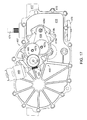
As shown in, e.g., FIGS. 4 and 5 , gear chamber 31 c is sized to accommodate a reduction gear train 50 and a slip clutch 60. The reduction gear train 50 and slip clutch 60 are greased assemblies enclosed in gear chamber 31 c by a side housing 32. Side housing 32 is secured to main housing 31 by fasteners 34. A liquid sealant material or other means known in the art may be used to seal the housings. As best shown in FIGS. 6 and 7 reduction gear train 50 is constructed of a worm drive 55 engaged to a spur gear reduction 57 of several stages that terminates with a sector gear 59 adapted to receive the control shaft of a drive apparatus, e.g. trunnion arm 22. To aid such engagement, sector gear 59 is retained and aligned by a pocket 31 d formed in the sidewall of gear chamber 31 c, assisted by its mesh with drive gear 58. Slip clutch 60 is disposed between worm drive 55 and the spur gear reduction 57. It should be understood that the number of reduction stages and the specific gear ratios depicted herein are illustrative only, as these parameters (along with motor output capacity) may be selected for a desired torque output and precision of movement by electric actuator 30. Regardless of number, the various support shafts 57 a, 57 b of spur gear reduction 57 are supported by main housing 31 and side housing 32. Worm drive 55, in combination with spur gear reduction 57, can be constructed to achieve, for example, a 3000:1 reduction with its resultant torque multiplication.
As shown most clearly in FIGS. 6 and 6A , worm drive 55 features a worm 41 fixedly disposed on the motor output shaft 40 b of electric motor 40, which in turn engages a worm gear 51 rotatably disposed on clutch support shaft 61. Worm 41 may be press-fit to motor output shaft 40 b to rotate therewith, or may be secured by other known means. Worm drive 55 is a self-locking design to prevent unwanted movement of the control shaft after a desired control position is established. This feature prevents unnecessary dithering of the electric motor 40 when, for example, increased hydraulic pressure in a drive system featuring variable displacement pump 21 acts against a rotatable swash plate (not shown) engaged to and controlled by trunnion arm 22, rotating the assembly away from its desired position and resultant displacement. The inner workings of an axial piston hydraulic pump, such as variable displacement pump 21, are disclosed in commonly-owned U.S. Pat. No. 6,332,393 and will not be further detailed herein. Seal 44 is disposed adjacent a first end of worm 41 to seal motor chamber 31 a from gear chamber 31 c, and bushing 42 is disposed on the opposite end to support worm 41 in housing 31. It will be understood that certain components in FIG. 6A , such as motor 40 and motor output shaft 40 b, are not cross-sectioned, as such cross-sectioning would not add to the understanding of the figure but would instead add unnecessary complexity.
When electric motor 40 is actuated, motive force is transmitted through reduction gear train 50 to trunnion arm 22. As a result, sector gear 59 causes trunnion arm 22 and its corresponding swash plate (not shown) to rotate. This adjustment of swash plate angle controls both the volume and direction of hydraulic fluid flow from variable displacement pump 21. Electric motor 40, under the influence of appropriate control logic, is capable of driving worm 41 both clockwise and counterclockwise to produce such adjustment.
Critical to the function of electric actuator 30 is control shaft position sensing. This may be accomplished by locating an angular position sensor 46 at the external end of trunnion arm 22. Angular position sensor 46 may incorporate Hall Effect technology to provide a linear response to the angular rotation of trunnion arm 22. Angular position sensor 46 may be fixed to a mounting boss 32 a formed external to side housing 32 after trunnion arm 22 is inserted through electric actuator 30 in a set process that aids calibration of the unit. Fasteners 48 may be used to retain angular position sensor 46 in place, while an O-ring 46 b (as shown in FIG. 7 ) seals the interface between angular position sensor 46 and mounting boss 32 a. Although angular position sensor 46 is depicted as engaging the external end of trunnion arm 22, it should be understood that a position sensor could be located to monitor the rotational position of any of the gears of spur gear reduction 57, such as drive gear 58.
Prior to insertion, trunnion arm 22 is rotated to a neutral displacement position established during functional testing of variable displacement pump 21. It is desirable to establish a neutral position for the control shaft of any drive apparatus to which electric actuator 30 is applied, prior to assembly with electric actuator 30. A plastic bullet 27 may be utilized to assist with the insertion of trunnion arm 22 through control shaft seal 38, shielding the splines 22 a of trunnion arm 22 to reduce the likelihood of creating a tear in control shaft seal 38. Following insertion, bullet 27 remains disposed about trunnion arm 22 adjacent to a protrusion 31 b of main housing 31. The protrusion 31 b is sized to accommodate control shaft seal 38 and a control shaft bushing 39, through which trunnion arm 22 also passes. Bullet 27 must then be withdrawn from control shaft seal 38 to permit proper sealing about trunnion arm 22. Bullet 27 may remain in place about trunnion arm 22, serving as protection for the control shaft seal 38 from dirt, debris or water spray, or it may be destructively removed. Trunnion arm 22 then fixedly engages and passes through sector gear 59. Proper positioning of sector gear 59 on trunnion arm 22 may be achieved by a clocking of the engagement splines 59 a of sector gear 59 and the complementary splines 22 a of trunnion arm 22. This optional alignment feature ensures that sector gear 59 is at the midpoint of its functional arc when trunnion arm 22 is at its neutral position. At this point in the assembly, fasteners 24 may be used to secure electric actuator 30 to mounting plate 23.
An adapter 47, whose engagement splines 47 b may be formed with the same clocking feature, is then fitted to the tip of trunnion arm 22. Alternatively, engagement splines 47 b may be formed with a spiral cut of a few degrees to create an interference fit with the straight splines 22 a of trunnion arm 22 when pressed together. Adapter 47 has a tang 47 a adapted to mechanically engage a slot 46 a in a rotatable portion of angular position sensor 46. It should be understood that the exact form of tang 47 a and the complementary form in the rotatable portion of angular position sensor 46 may have a different shape, e.g. a cross shape or a hexagonal shape. Tang 47 a is positioned relative to its clocking feature such that angular position sensor 46 must be rotated against its internal return spring (not shown) to approximately the midpoint of its sensing range to be properly aligned for mounting on mounting boss 32 a. In this manner, the neutral position of trunnion arm 22 and its corresponding swash plate (not shown) is mechanically and electronically aligned with the midpoint of the sensing range of angular position sensor 46. The angular position sensor 46 may then be connected by a wiring harness (as schematically shown in FIG. 12 to a controller, such as drive controller 170, to communicate the position of trunnion arm 22 to the controller. It should be noted that electric motor 40 is also placed in electrical communication with drive controller 170 by connection of the referenced wiring harness to electric connector 45. Thus, drive controller 170 modulates the desired position of trunnion arm 22 and its corresponding swash plate (not shown) by supplying a controlled voltage or current to electric motor 40 with positional feedback from angular position sensor 46.
Slip clutch 60 protects the gears of reduction gear train 50 from excessive torque and is detailed in FIGS. 8-11 . Slip clutch 60 acts to uncouple worm gear 51 from pinion gear 52 when resistance to movement, or excess loading of the reduction gear train 50, is present and sufficient torque is generated by electric motor 40 to overcome the spring force of clutch spring 63. This condition may occur, for example, when electric actuator 30 is bench tested for maintenance purposes. In such an instance, application of power directly to electric actuator 30, without a controller in the test circuit to limit travel of sector gear 59, may cause sector gear 59 to be driven against a sidewall of gear chamber 31 c, increasing the loading on all gear teeth as the reduction gear train 50 attempts to rotate. In the absence of slip clutch 60, gear teeth, such as those of sector gear 59 and drive gear 58, may break if electric motor 40 has sufficient torque capacity. When electric actuator 30 is applied to the control shaft of a drive apparatus, slip clutch 60 may be set (via choice of clutch spring 63) to a specific torque limit to further protect the internal components of the drive apparatus.
Slip clutch 60 is an assembly disposed about clutch support shaft 61, which is supported at opposing ends by main housing 31 and side housing 32. Clutch pins 62 are slidingly disposed in a plurality of bores 51 a formed in worm gear 51 that are generally disposed radially about, and parallel to, clutch support shaft 61. Clutch pins 62 have first ends which engage various features on the side of pinion gear 52, and second ends which engage a thrust washer 64 b that moves axially along clutch support shaft 61 as slip clutch 60 functions. Slip clutch 60 is bookended by a pair of thrust washers 64 a, 64 c that are retained in fixed positions along the length of clutch support shaft 61 by side housing 32 and main housing 31, respectively. Main housing 31 also limits axial movement of worm gear 51 along clutch support shaft 61 to prevent worm gear 51 from being disengaged from worm 41 during operation. A clutch spring 63 is disposed about clutch support shaft 61 and bears against both thrust washer 64 b and thrust washer 64 a. The spring force of clutch spring 63 couples worm gear 51 and pinion gear 52, permitting the transfer of motive force from electric motor 40 through reduction gear train 50 to a control shaft. More specifically, the spring force of clutch spring 63 causes thrust washer 64 b to bear against clutch pins 62, which in turn bear against the ramps 52 b of projections 52 a formed on the side of pinion gear 52, and also bear against the gaps 52 c located between the projections 52 a. Thus, when worm gear 51 rotates, pinion gear 52 is rotated and rides against thrust washer 64 c. When resistance to movement, or excess loading, is present in reduction gear train 50, however, and sufficient torque is generated by electric motor 40, the force of clutch spring 63 is overcome and the first ends of clutch pins 62 traverse the ramps 52 b of the projections 52 a and slip from gap to gap on the side of pinion gear 52. (As this occurs, the periodic axial movement of clutch pins 62 through bores 51 a forces thrust washer 64 b to periodically compress clutch spring 63.) Thus, worm gear 51 is momentarily uncoupled from pinion gear 52 and motive force is no longer transmitted through spur gear reduction 57. When resistance to movement, or excess loading, is no longer sufficiently present in reduction gear train 50, clutch pins 62 will cease to traverse the ramps 52 b of the projections 52 a and thereafter reside in gaps 52 c under the influence of clutch spring 63. Thus, worm gear 51 will again be coupled to pinion gear 52 to drive spur gear reduction 57.
To generate steering inputs for a drive controller 170, a steering wheel 180, steering column 181 and steering position sensor 171 (e.g. a potentiometer to indicate the rotational position of steering column 181) are provided. To generate speed inputs (amplitude) and direction inputs (forward or reverse), an accelerator pedal 172, such as a rocker-style pedal, is provided which also incorporates a position sensor (not shown). Drive controller 170 receives and processes input signals from the position sensor of accelerator pedal 172 and the steering position sensor 171 to generate control signals (generally, an applied voltage or current) for the electric motors 40 of the electric actuators 30. In order to more finely tune the desired position of trunnion arms 22 and the corresponding output of the variable displacement pumps 21, drive controller 170 further receives feedback from the angular position sensors 46 of the electric actuators 30, and optionally may also receive and use feedback from a pair of axle speed sensors 173. A description of various control algorithms for an electric actuator that provide vehicle drive characteristics and safety features is detailed in commonly-owned U.S. Patent Pub. No. 2008/0018269, the terms of which are incorporated herein by reference, and shall not be further described herein. Electrical energy may be supplied to drive controller 170 by an independent electrical power source, such as a battery (not shown), or an alternator or generator (not shown) associated with prime mover 191.
The permitted range of motion that electric actuator 30 imparts to a control shaft, such as the trunnion arm 22 of variable displacement pump 21, 321, may be calibrated in association with application of drive assembly 20, 320 to the end-use vehicle or other mobile power equipment. After the previously described mounting of electric actuator 30 to variable displacement pump 21, 321, wherein the neutral position of trunnion arm 22 and its corresponding swash plate (not shown) is mechanically and electronically aligned with the midpoint of the sensing range of angular position sensor 46, drive assembly 20, 320 is mounted to a vehicle, such as zero turn vehicle 190, 290, 390, or other mobile power equipment, and placed in electronic communication with a controller, such as drive controller 170, 270, 370. Electric motor 40 is slowly driven in a first rotational direction until trunnion arm 22 and its corresponding swash plate are rotated away from the neutral position and the swash plate encounters a first mechanical stop within the housing of variable displacement pump 21. Drive controller 170, 270, 370 senses and learns this positional limit by the cessation of a change in angular position feedback from angular position sensor 46 and a spike in applied voltage as resistance to motion in the reduction gear train 50 builds. The dimensions of gear chamber 31 c are such that sector gear 59 does not encounter a sidewall of gear chamber 31 c when the swash plate hits its mechanical limit of angular rotation. Electric motor 40 is then slowly driven in a second rotation direction until trunnion arm 22 and its corresponding swash plate are rotated past neutral to a second mechanical stop within the housing of variable displacement pump 21, 321. Drive controller 170, 270, 370 again senses and learns the positional limit. It is desirable to program an offset of a few rotational degrees from these positional limits into controller 170, 270, 370 to protect the components of variable displacement pump 21, 321. The neutral position of variable displacement pump 21, 321 may be calculated by drive controller 170, 270, 370 as the midpoint of the sensing range between the two offsets. In a vehicle such as zero turn vehicle 190, 290, 390, additional fine tuning of the neutral point is optionally provided by additional feedback to drive controller 170, 270, 370 from axle speed sensors 173, 273, 373 that monitor rotational movement of the axles of hydraulic motors 194L, 194R, 294L, 294R, 394L, 394R. In actuality, it is desirable to program a neutral dead band in drive controller 170 to prevent aggressive drive characteristics upon initial actuation of accelerator pedal 172. A control algorithm related to neutral dead bands is detailed in commonly-owned U.S. Patent Pub. No. 2008/0018269, and shall not be further described herein.
A further embodiment is depicted in FIGS. 16 to 22 , for applications using zero turn hydrostatic transaxles 420L and 420R, where each actuator is integrated with its respective transaxle to reduce or eliminate the need for separate actuator housings.
Except as described herein, the internal structure and operation of transaxles 420L and 420R can be substantially identical to that shown and described in commonly-owned U.S. Pat. No. 7,134,276, the terms of which are incorporated herein by reference in their entirety. FIG. 19 shows the internal structure of transaxles 420L, 420R, including hydraulic pump 421 rotatably disposed on center section 475 in main sump chamber 469 and controlled by swash plate 429. Hydraulic motor 494 is similarly disposed in main sump chamber 469 and drives motor output shaft 477, which in turn powers reduction gear train 478 to provide motive force to output axle 479. Pump input shaft 474 provides motive force to pump 421 and may also drive an optional charge pump 476.
In another embodiment of the clutch assembly, depicted in FIG. 21 , a clutch spring compression adjustment mechanism 449 is included, and comprises a clutch shaft support screw 466 configured to receive an end 461 b of support shaft 461 within a bore 466 a and having external threads 466 c to engage an opening (not shown) in actuator housing 428, and whose relative location along support shaft 461 is secured by means of locking nuts 468 a, 468 b. Hex 466 b enables external adjustment of the compression of spring 463, whereby rotation of hex 466 b causes clutch shaft support screw 466 to adjust the position of washer 464 a, changing the compression of spring 463. Unlike prior embodiments, wherein the position of the outermost washer was fixed, washer 464 a must be free to travel along support shaft 461 in this adjustable application. FIG. 24 shows yet another embodiment of an alternative clutch spring compression adjustment mechanism 749 for clutch assembly 760. Clutch support shaft 761 has an enlarged end 761 a that engages shoulder 718 g in side housing 718 to limit its range of axial movement. Support shaft 761 extends out boss 718 f formed in side housing 718, and the opposite end 761 b of support shaft 761 is threaded and extends out of actuator housing 728 through nut 756, which may be in the shape of a wing nut or the like, and which enables adjustment of the compression of spring 763 by rotation of nut 756 and engagement with washer 764 a. Locking nut 768 is also provided to lock nut 756 in place after proper adjustment is made. Other elements of this design, such as washers 764 b, 764 c, worm gear 751, pinion gear 752, spacer 765 and clutch pins 762 may be similar to those previously described. It will be understood that in these embodiments appropriate seals or sealants, such as seal 767 in FIG. 24 , may need to be used.
While specific embodiments have been described in detail, it will be appreciated by those skilled in the art that various modifications and alternatives to those presented herein could be developed in light of the overall teachings of the disclosure. Accordingly, the particular arrangements disclosed are meant to be illustrative only and not limiting as to the scope of the invention which is to be given the full breadth of the appended claims and any equivalent thereof.
Claims (21)
1. A drive apparatus disposed in a housing, comprising:
a hydraulic drive disposed in the housing and comprising at least one hydraulic pump and a control shaft for controlling output of the at least one hydraulic pump; and
an electric actuator in communication with a drive controller for adjusting a rotational position of the control shaft, the electric actuator comprising:
an electric motor comprising a plurality of electric contacts and a motor output shaft;
a gear reduction assembly engaged to the control shaft to adjust its rotational position; and
an angular position sensor to communicate the rotational position of the control shaft to the drive controller;
wherein the gear reduction assembly and the at least one hydraulic pump are both disposed in the housing and share hydraulic oil;
wherein the housing comprises:
a main housing having a side housing engaged thereto to form a first space, the side housing having an internal side and an external side; and
an actuator housing engaged to the external side of the side housing to form a second space in fluid communication with the first space through an opening in the side housing; and
wherein the at least one hydraulic pump is disposed in the first space and the gear reduction assembly is disposed in the second space.
2. The drive apparatus of claim 1 , wherein the gear reduction assembly comprises:
a plurality of gears and a plurality of jack shafts, wherein each one of plurality of gears is disposed on one of the plurality of jack shafts; and
a plurality of bosses formed in the external side of the side housing, each of the plurality of bosses supporting one of the plurality of jack shafts.
3. The drive apparatus of claim 1 , wherein the at least one hydraulic pump comprises a single pump hydraulically connected to a single motor, and a swash plate for engaging a set of pump pistons for altering the output of the single pump to the single motor, wherein the control shaft is engaged to the swash plate.
4. The drive apparatus of claim 3 , wherein the control shaft is integrally formed on one side of the swash plate.
5. The drive apparatus of claim 3 , further comprising an adapter on the control shaft, wherein the adapter mechanically engages the angular position sensor to communicate the rotational position of the control shaft.
6. The drive apparatus of claim 5 , wherein the adapter is integrally formed on the control shaft.
7. The drive apparatus of claim 1 , wherein the angular position sensor is engaged to the control shaft.
8. The drive apparatus of claim 1 , further comprising a worm driven by the motor output shaft and engaged to and driving a worm gear, the worm gear engaged to and driving at least one pinion gear in the gear reduction assembly.
9. The drive apparatus of claim 8 , wherein the worm has a first end engaged to and driven by the motor output shaft and a second end supported by a bearing in the housing.
10. The drive apparatus of claim 8 , wherein the gear reduction assembly further comprises a slip clutch engaged to the at least one pinion gear.
11. The drive apparatus of claim 10 , wherein the slip clutch comprises:
a clutch support shaft extending through the worm gear and the at least one pinion gear;
a plurality of clutch pins arranged radially around the clutch support shaft and extending through the worm gear, each clutch pin having a first end engaging a ramp formed on a side surface of the at least one pinion gear and a second end engaging a first thrust washer, whereby each clutch pin is capable of transferring rotational force from the worm gear to the at least one pinion gear; and
a spring disposed about the clutch support shaft and between the first thrust washer and a second thrust washer, wherein the slip clutch permits the at least one pinion gear to disengage from the worm gear.
12. The drive apparatus of claim 11 , further comprising a clutch adjustment mechanism disposed on one end of the clutch support shaft to permit adjustment of a compression of the spring, wherein at least a portion of the clutch adjustment mechanism is disposed external to the housing.
13. The drive apparatus of claim 12 , wherein the clutch adjustment mechanism comprises a clutch shaft support screw mounted on the one end of the clutch support shaft, and a plurality of locking nuts disposed on a threaded portion of the clutch shaft support screw, whereby the plurality of locking nuts act to move the clutch shaft support screw to change a position of the second thrust washer to change the compression of the spring.
14. A drive apparatus, comprising:
a housing forming a fluid sump;
a variable transmission disposed in the fluid sump; and
an actuator for varying output of the variable transmission, comprising:
a gear assembly disposed in the fluid sump; and
an electric motor engaged to the gear assembly to control the actuators;
wherein the housing comprises:
a main housing having a side housing engaged thereto to form a first space, the side housing having an internal side and an external side; and
an actuator housing engaged to the external side of the side housing to form a second space in fluid communication with the first space through an opening in the side housing;
wherein the first space and the second space combine to form the fluid sump.
15. The drive apparatus of claim 14 , wherein:
the electric motor drives a motor output shaft, and a worm is rotatably driven by the motor output shaft; and
the variable transmission comprises a control shaft, whereby the actuator is engaged to and rotates the control shaft to vary the output of the variable transmission, and an angular position sensor is engaged to the control shaft to communicate a rotational position of the control shaft to a drive controller.
16. A drive apparatus comprising:
a housing forming a fluid sump;
a variable transmission disposed in the fluid sump; and
an actuator for varying output of the variable transmission, comprising:
a gear assembly disposed in the fluid sump; and
an electric motor engaged to the gear assembly to control the actuator;
wherein:
the electric motor drives a motor output shaft, and a worm is rotatably driven by the motor output shaft;
the variable transmission comprises a control shaft, whereby the actuator is engaged to and rotates the control shaft to vary the output of the variable transmission, and an angular position sensor is engaged to the control shaft to communicate a rotational position of the control shaft to a drive controller;
the gear assembly comprises a worm gear engaged to and driven by the worm and at least one pinion gear; and
a slip clutch is engaged to the at least one pinion gear, the slip clutch comprising:
a clutch support shaft extending through the worm gear and the at least one pinion gear;
a plurality of clutch pins arranged radially around the clutch support shaft and extending through the worm gear, each clutch pin having a first end engaging a ramp formed on a side surface of the at least one pinion gear and a second end engaging a first thrust washer, whereby each clutch pin is capable of transferring rotational force from the worm gear to the at least one pinion gear; and
a spring disposed about the clutch support shaft and between the first thrust washer and a second thrust washer, wherein the slip clutch permits the at least one pinion gear to disengage from the worm gear.
17. The drive apparatus of claim 16 , further comprising a clutch adjustment mechanism disposed on one end of the clutch support shaft to permit adjustment of a compression of the spring, wherein at least a portion of the clutch adjustment mechanism is disposed external to the housing.
18. The drive apparatus of claim 17 , wherein the clutch adjustment mechanism comprises a clutch shaft support screw mounted on the one end of the clutch support shaft, and a plurality of locking nuts disposed on a threaded portion of the clutch shaft support screw, whereby the plurality of locking nuts act to move the clutch shaft support screw to change a position of the second thrust washer to change the compression of the spring.
19. A vehicle comprising:
a drive controller;
a prime mover having an output shaft; and
a first variable drive unit for driving a first wheel of the vehicle and a second variable drive unit for driving a second wheel of the vehicle, the first variable drive unit and the second variable drive unit each comprising:
a housing forming a fluid sump;
a hydraulic pump disposed in the fluid sump and controlled by a control shaft and hydraulically connected to a hydraulic motor; and
an electric actuator in communication with the drive controller for adjusting a rotational position of the control shaft, the electric actuator comprising:
an electric motor comprising a motor output shaft; and
a spur gear reduction disposed in the fluid sump, whereby the spur gear reduction shares common oil with the hydraulic pump, the spur gear reduction being driven by the motor output shaft and engaged to the control shaft to adjust a rotational position of the control shaft;
wherein the housing of the first variable drive unit and the housing of the second variable drive unit each further comprise a main housing engaged with a side housing and an actuator housing engaged to an external surface of the side housing, the main housing and the side housing defining a first space, the actuator housing defining a second space, wherein the first space is in fluid communication with the second space via an opening in the side housing to form the fluid sump.
20. The vehicle of claim 19 , wherein each electric actuator further comprises a worm engaged to and driven by the motor output shaft, and each spur gear reduction comprises a worm gear driven by the worm and a slip clutch between the worm gear and the spur gear reduction.
21. The vehicle of claim 20 , wherein each electric actuator further comprises an angular position sensor disposed on the housing, wherein each angular position sensor engages a first end of the control shaft and communicates its rotational position to the drive controller.
Priority Applications (1)
| Application Number | Priority Date | Filing Date | Title |
|---|---|---|---|
| US14/833,617 US9765761B1 (en) | 2012-12-12 | 2015-08-24 | Electric actuator for drive apparatus |
Applications Claiming Priority (4)
| Application Number | Priority Date | Filing Date | Title |
|---|---|---|---|
| US201261736115P | 2012-12-12 | 2012-12-12 | |
| US201361782218P | 2013-03-14 | 2013-03-14 | |
| US14/104,979 US9114798B1 (en) | 2012-12-12 | 2013-12-12 | Electric actuator for drive apparatus |
| US14/833,617 US9765761B1 (en) | 2012-12-12 | 2015-08-24 | Electric actuator for drive apparatus |
Related Parent Applications (1)
| Application Number | Title | Priority Date | Filing Date |
|---|---|---|---|
| US14/104,979 Continuation US9114798B1 (en) | 2012-12-12 | 2013-12-12 | Electric actuator for drive apparatus |
Publications (1)
| Publication Number | Publication Date |
|---|---|
| US9765761B1 true US9765761B1 (en) | 2017-09-19 |
Family
ID=53838337
Family Applications (6)
| Application Number | Title | Priority Date | Filing Date |
|---|---|---|---|
| US14/104,979 Active US9114798B1 (en) | 2012-12-12 | 2013-12-12 | Electric actuator for drive apparatus |
| US14/833,617 Active US9765761B1 (en) | 2012-12-12 | 2015-08-24 | Electric actuator for drive apparatus |
| US14/833,595 Active 2034-03-03 US9765870B1 (en) | 2012-12-12 | 2015-08-24 | Electric actuator for drive apparatus |
| US15/707,564 Active 2034-04-05 US10584780B1 (en) | 2012-12-12 | 2017-09-18 | Electric actuator for drive apparatus |
| US16/812,607 Active US11466764B1 (en) | 2012-12-12 | 2020-03-09 | Vehicle having electric actuator |
| US18/045,383 Active US11725716B1 (en) | 2012-12-12 | 2022-10-10 | Electric actuator for drive apparatus |
Family Applications Before (1)
| Application Number | Title | Priority Date | Filing Date |
|---|---|---|---|
| US14/104,979 Active US9114798B1 (en) | 2012-12-12 | 2013-12-12 | Electric actuator for drive apparatus |
Family Applications After (4)
| Application Number | Title | Priority Date | Filing Date |
|---|---|---|---|
| US14/833,595 Active 2034-03-03 US9765870B1 (en) | 2012-12-12 | 2015-08-24 | Electric actuator for drive apparatus |
| US15/707,564 Active 2034-04-05 US10584780B1 (en) | 2012-12-12 | 2017-09-18 | Electric actuator for drive apparatus |
| US16/812,607 Active US11466764B1 (en) | 2012-12-12 | 2020-03-09 | Vehicle having electric actuator |
| US18/045,383 Active US11725716B1 (en) | 2012-12-12 | 2022-10-10 | Electric actuator for drive apparatus |
Country Status (1)
| Country | Link |
|---|---|
| US (6) | US9114798B1 (en) |
Cited By (8)
| Publication number | Priority date | Publication date | Assignee | Title |
|---|---|---|---|---|
| US10278332B2 (en) * | 2016-10-05 | 2019-05-07 | Deere & Company | Chopper timing adjustment |
| US10753470B1 (en) | 2016-10-13 | 2020-08-25 | Hydro-Gear Limited Partnership | Electric actuator for use on a hydraulic drive device |
| US10890253B1 (en) | 2017-04-04 | 2021-01-12 | Hydro-Gear Limited Partnership | Electric actuator for drive apparatus |
| US11211844B1 (en) * | 2018-06-29 | 2021-12-28 | Hydro-Gear Limited Partnership | Electric motor and brake assembly |
| US11641795B2 (en) | 2018-09-27 | 2023-05-09 | Nanjing Chervon Industry Co., Ltd. | Lawn mower |
| USD987691S1 (en) | 2018-09-27 | 2023-05-30 | Nanjing Chervon Industry Co., Ltd. | Mower blade assembly |
| USD995569S1 (en) | 2019-04-18 | 2023-08-15 | Nanjing Chervon Industry Co., Ltd. | Mower blade assembly |
| US11901793B1 (en) | 2017-04-04 | 2024-02-13 | Hydro-Gear Limited Partnership | Electric actuator and vibration damping apparatus for drive apparatus |
Families Citing this family (29)
| Publication number | Priority date | Publication date | Assignee | Title |
|---|---|---|---|---|
| US9944316B2 (en) * | 2012-04-24 | 2018-04-17 | Mtd Products Inc | Vehicle drive control systems and the related vehicles |
| US9114798B1 (en) | 2012-12-12 | 2015-08-25 | Hydro-Gear Limited Partnership | Electric actuator for drive apparatus |
| US10180180B2 (en) * | 2013-09-25 | 2019-01-15 | Medela Holding Ag | Gear motor pump assembly |
| US9725114B1 (en) | 2014-07-03 | 2017-08-08 | Hydro-Gear Limited Partnership | Control system for a vehicle |
| US9864396B1 (en) | 2014-08-05 | 2018-01-09 | Hydro-Gear Limited Partnership | Highly maneuverable mowing vehicle with Mecanum wheels |
| US10629005B1 (en) | 2014-10-20 | 2020-04-21 | Hydro-Gear Limited Partnership | Interactive sensor, communications, and control system for a utility vehicle |
| US9867331B1 (en) | 2014-10-28 | 2018-01-16 | Hydro-Gear Limited Partnership | Utility vehicle with onboard and remote control systems |
| US10058031B1 (en) | 2015-02-28 | 2018-08-28 | Hydro-Gear Limited Partnership | Lawn tractor with electronic drive and control system |
| US10392007B1 (en) | 2015-03-26 | 2019-08-27 | Hydro-Gear Limited Partnership | Stability control system |
| US9840143B1 (en) | 2015-05-20 | 2017-12-12 | Hydro-Gear Limited Partnership | Cooling pump assembly and cooling system for utility vehicle |
| US10106027B1 (en) | 2015-06-01 | 2018-10-23 | Hydro-Gear Limited Partnership | Generator/cooling assembly and system for utility vehicle |
| US10358040B1 (en) | 2015-06-01 | 2019-07-23 | Hydro-Gear Limited Partnership | Drive assembly and system for utility vehicle |
| US10391854B1 (en) | 2015-06-15 | 2019-08-27 | Hydro-Gear Limited Partnership | Drive and cooling system for utility vehicle |
| US10093169B1 (en) | 2015-07-09 | 2018-10-09 | Hydro-Gear Limited Partnership | Power and cooling system for utility vehicle |
| US10563761B2 (en) * | 2015-08-07 | 2020-02-18 | Yanmar Co., Ltd. | Work vehicle |
| KR102408251B1 (en) * | 2015-10-01 | 2022-06-13 | 엘지이노텍 주식회사 | Parking brake actuator |
| US10955051B2 (en) | 2017-07-18 | 2021-03-23 | Dura Operating, Llc | Actuator assembly for a transmission shifter |
| US11149846B2 (en) * | 2017-07-18 | 2021-10-19 | Dus Operating Inc. | Actuator assembly for a transmission shifter |
| JP7056162B2 (en) * | 2018-01-17 | 2022-04-19 | 株式会社デンソー | Motor with deceleration mechanism |
| CN112041129B (en) * | 2018-03-28 | 2023-10-10 | 罗博力坚特有限公司 | Rotary tandem elastic actuator |
| US10589623B1 (en) | 2018-09-19 | 2020-03-17 | Textron Innovations Inc. | Floating engine powertrain |
| US10889173B2 (en) * | 2018-09-19 | 2021-01-12 | Textron Inc. | Powertrain |
| US11547052B1 (en) | 2018-10-10 | 2023-01-10 | Hydro-Gear Limited Partnership | Audible operator feedback for riding lawn mower applications |
| JP2020088962A (en) * | 2018-11-20 | 2020-06-04 | 日本電産サンキョー株式会社 | Actuator, clutch device, and washing machine |
| US10965189B2 (en) * | 2019-08-13 | 2021-03-30 | Bühler Motor GmbH | Actuator for a drug administrating device |
| DE102020112548A1 (en) * | 2020-05-08 | 2021-11-11 | Auma Riester Gmbh & Co. Kg | Fail-safe drive and actuator with a fail-safe drive |
| CN112676895A (en) * | 2021-01-06 | 2021-04-20 | 陈霞 | Motion limiting structure for driving device for machining |
| IT202100005639A1 (en) * | 2021-03-10 | 2022-09-10 | Giotto Srl | CALIBRATION AND/OR PRESSURIZATION DEVICE |
| JP2023095653A (en) * | 2021-12-24 | 2023-07-06 | 株式会社クボタ | Service car |
Citations (59)
| Publication number | Priority date | Publication date | Assignee | Title |
|---|---|---|---|---|
| US1418325A (en) | 1920-06-19 | 1922-06-06 | Sperry Gyroscope Co Ltd | Searchlight-positioning means |
| US2142171A (en) | 1938-07-16 | 1939-01-03 | John B Boyd | Visual educational device |
| US3054310A (en) | 1959-05-21 | 1962-09-18 | Industrial Nucleonics Corp | Control system |
| US3646754A (en) | 1970-05-22 | 1972-03-07 | Ltv Electrosystems Inc | Motor operated servo pump |
| US3733970A (en) | 1970-07-29 | 1973-05-22 | Bosch Gmbh Robert | Axial piston machine with adjustable swash plate |
| US4624175A (en) | 1985-08-28 | 1986-11-25 | Wahlmark Gunnar A | Quiet hydraulic apparatus |
| EP0223682A1 (en) | 1985-10-30 | 1987-05-27 | Electricite De France | Sound mapping device |
| EP0271744A2 (en) | 1986-11-24 | 1988-06-22 | Liebherr-Aero-Technik GmbH | Electric-hydraulic actuator |
| US4827721A (en) | 1986-10-29 | 1989-05-09 | Honda Giken Kogyo Kabushiki Kaisha | Hydrostatic continuously variable transmission |
| US4854125A (en) | 1987-02-20 | 1989-08-08 | Honda Giken Kogyo Kabushiki Kaisha | Hydrostatically operated continuously variable transmission |
| US4875390A (en) | 1986-03-24 | 1989-10-24 | Honda Giken Kogyo Kabushiki Kaisha | Shift control device for hydrostatic continuously variable transmission |
| US4916901A (en) | 1987-07-03 | 1990-04-17 | Honda Giken Kogyo Kabushiki Kaisha | Swashplate type variable displacement hydraulic device |
| US4951469A (en) | 1987-09-21 | 1990-08-28 | Honda Giken Kogyo Kabushiki Kaisha | Hydrostatic continuously variable transmission |
| US4984161A (en) | 1987-03-24 | 1991-01-08 | Honda Giken Kogyo Kabushiki Kaisha | Method for controlling automatic transmissions |
| US4991492A (en) | 1988-11-30 | 1991-02-12 | Stig Bratt | Hydrostatic axial piston machine |
| USRE34064E (en) | 1987-07-16 | 1992-09-15 | Automotive Products (Usa) Inc. | Electric shift apparatus |
| US5584214A (en) | 1993-10-19 | 1996-12-17 | Honda Giken Kogyo Kabushiki Kaisha | Transmission having a static, hydraulic continuously-variable-speed transmission mechanism |
| US6122996A (en) | 1998-11-20 | 2000-09-26 | Hydro-Gear Limited Partnership | Hydrostatic transmission |
| US6138069A (en) | 1999-05-24 | 2000-10-24 | Textron Inc. | Utility vehicle with work-performing attachment |
| US6176684B1 (en) | 1998-11-30 | 2001-01-23 | Caterpillar Inc. | Variable displacement hydraulic piston unit with electrically operated variable displacement control and timing control |
| US6229226B1 (en) | 1999-03-26 | 2001-05-08 | Donnelly Corporation | Vehicular exterior rear view mirror actuator with emission suppression |
| US6229233B1 (en) | 1999-05-06 | 2001-05-08 | Asmo Co., Ltd. | Motor having worm gear mechanism |
| JP2001349427A (en) | 2000-06-05 | 2001-12-21 | Yuhshin Co Ltd | Hst trunnion shaft driving device |
| US6332393B1 (en) | 1999-07-16 | 2001-12-25 | Hydro-Gear Limited Partnership | Pump |
| US6343470B1 (en) | 1999-09-05 | 2002-02-05 | Honda Giken Kogyo Kabushiki Kaisha | Control method for hydrostatic type continuously variable transmission |
| US6481203B1 (en) | 1999-06-10 | 2002-11-19 | Tecumseh Products Company | Electric shifting of a variable speed transmission |
| US6487857B1 (en) | 2001-02-20 | 2002-12-03 | Hydro-Gear Limited Partnership | Zero-turn transaxle with mounted return to neutral mechanism |
| US6494686B1 (en) | 2000-10-30 | 2002-12-17 | Hydro-Gear Limited Partnership | Tandem pump and interface for same |
| US6707188B2 (en) | 2000-05-08 | 2004-03-16 | Asmo Co., Ltd. | Motor having rotational sensor |
| US6759783B2 (en) | 2000-02-19 | 2004-07-06 | Robert Bosch Gmbh | Electric motor, in particular for raising and lowering disks in motor vehicles |
| US6775976B1 (en) | 2002-07-31 | 2004-08-17 | Hydro-Gear Limited Partnership | Zero-turn hydrostatic transaxle |
| US6951164B2 (en) | 2003-03-31 | 2005-10-04 | Honda Motor Co., Ltd. | Swash plate type servo device for a plunger hydraulic unit |
| US6955046B1 (en) | 2002-11-07 | 2005-10-18 | Hydro-Gear Limited Partnership | System and method for electronic actuation of axle driving apparatus |
| US6971942B2 (en) | 2001-02-09 | 2005-12-06 | Mattel, Inc. | Rotary feedback mechanism for a toy |
| US7055795B2 (en) | 2003-07-17 | 2006-06-06 | Rotork Controls Limited | Drive mechanisms for valve actuators |
| US7062909B2 (en) | 2003-03-31 | 2006-06-20 | Honda Motor Co., Ltd. | Hydraulic continuously variable transmission |
| US7076948B2 (en) | 2003-03-31 | 2006-07-18 | Honda Motor Co., Ltd. | Hydraulic continuously variable transmission |
| US7134276B1 (en) | 2004-05-18 | 2006-11-14 | Hydro-Gear Limited Partnership | Cylinder block brake for a hydrostatic drive apparatus |
| US20060272495A1 (en) | 2005-05-18 | 2006-12-07 | Ryota Ohashi | Hydraulic pump unit |
| US7152403B2 (en) | 2004-03-22 | 2006-12-26 | Honda Motor Co., Ltd. | Power unit |
| US7165398B1 (en) * | 2002-11-07 | 2007-01-23 | Hydro-Gear Limited Partnership | System and method for electronic actuation of axle driving apparatus |
| JP2007092909A (en) | 2005-09-29 | 2007-04-12 | Kubota Corp | Gear shifting operation device and combined harvester provided with it |
| US7247004B2 (en) | 2002-03-27 | 2007-07-24 | Hitachi, Ltd. | Electronically controlled actuator |
| US20080018269A1 (en) * | 2006-07-07 | 2008-01-24 | Hydro-Gear Limited Partnership | Electronic Steering Apparatus |
| JP2008055965A (en) | 2006-08-29 | 2008-03-13 | Iseki & Co Ltd | Working vehicle |
| US7503173B2 (en) | 2005-02-08 | 2009-03-17 | Parker-Hannifin Corporation | Control devices for swashplate type variable displacement piston pump |
| US7506729B2 (en) | 2004-01-13 | 2009-03-24 | Smith Patents, Llc | Torque-limited electric servo system for deploying a vehicle snow chain traction system |
| US7728472B2 (en) | 2005-11-08 | 2010-06-01 | Robert Bosch Gmbh | Transmission drive unit with a plug-in electronics module |
| US8074451B2 (en) | 2008-06-02 | 2011-12-13 | Caterpillar Inc. | Electric motor actuation of a hydrostatic pump |
| US20120198994A1 (en) | 2011-02-07 | 2012-08-09 | Choi Chul Hwan | Apparatus for controlling the angle of a swash plate of a hydraulic pump |
| US8250862B1 (en) | 2007-09-21 | 2012-08-28 | Kanzaki Kokyukoki Mfg. Co., Ltd. | Vehicle |
| US8490722B2 (en) | 2009-11-30 | 2013-07-23 | Kanzaki Kokyukoki Mfg. Co., Ltd. | Riding-type ground working vehicle |
| US8511216B2 (en) | 2009-03-30 | 2013-08-20 | Kanzaki Kokyukoki Mfg. Co., Ltd. | Hydraulic actuator unit |
| US8587170B2 (en) | 2008-05-21 | 2013-11-19 | Siemens Industry, Inc. | Actuator arrangement with worm gear and rotational output having an encoder |
| US20140361667A1 (en) | 2013-06-07 | 2014-12-11 | Johnson Electric S.A. | Actuator |
| US9067574B2 (en) | 2010-12-08 | 2015-06-30 | Honda Motor Co., Ltd. | Hydraulic modulator |
| US9080670B2 (en) | 2010-09-22 | 2015-07-14 | Aisin Seiki Kabushiki Kaisha | Power transmission device |
| US9114798B1 (en) | 2012-12-12 | 2015-08-25 | Hydro-Gear Limited Partnership | Electric actuator for drive apparatus |
| US9234582B2 (en) | 2009-10-21 | 2016-01-12 | Thomson Linear Llc | Apparatus and methods for controlling hydraulically-powered apparatus |
Family Cites Families (29)
| Publication number | Priority date | Publication date | Assignee | Title |
|---|---|---|---|---|
| FR490549A (en) * | 1918-06-17 | 1919-04-26 | Marcel Remy Brasseur | Automatic safety release |
| GB1600699A (en) | 1978-03-01 | 1981-10-21 | Besant C B | Electronically controlled hydraulic drive system |
| US4593800A (en) * | 1983-02-22 | 1986-06-10 | Helland Research & Engineering, Inc. | Torque release drive connector |
| US4616164A (en) * | 1984-03-28 | 1986-10-07 | Eaton Corporation | Feedback servo actuator |
| JPS61279742A (en) * | 1985-06-05 | 1986-12-10 | Nippon Denso Co Ltd | Throttle valve opening detector for vehicles |
| GB2188159B (en) * | 1986-03-19 | 1990-05-30 | Honda Motor Co Ltd | Angle-of-rotation sensor |
| DE3740490A1 (en) * | 1987-11-29 | 1989-06-08 | Intercoal Bergwerksmaschinen G | Positive-locking overload coupling |
| GB2248975B (en) | 1990-10-19 | 1994-10-12 | Johnson Electric Sa | Electric motor |
| US5363713A (en) * | 1993-04-29 | 1994-11-15 | Eaton Corporation | Quieted servoactuator |
| AUPM942394A0 (en) * | 1994-11-14 | 1994-12-08 | Britax Rainsfords Pty Ltd | A detent mechanism |
| US5983743A (en) * | 1997-04-03 | 1999-11-16 | Dresser Industries, Inc. | Actuator assembly |
| JP4025436B2 (en) * | 1998-02-17 | 2007-12-19 | アスモ株式会社 | motor |
| WO2000068555A1 (en) * | 1999-05-10 | 2000-11-16 | Hitachi, Ltd. | Throttle device of internal combustion engine |
| US6727613B2 (en) | 2001-04-25 | 2004-04-27 | Asmo Co., Ltd. | Motor having rotatable shaft coupled with worm shaft |
| DE10147225A1 (en) * | 2001-09-14 | 2003-04-10 | Brose Fahrzeugteile | Drive unit with an electric motor for adjusting devices in motor vehicles |
| JP4191940B2 (en) * | 2002-03-12 | 2008-12-03 | アルプス電気株式会社 | Rotary position sensor |
| JP2004141049A (en) | 2002-10-23 | 2004-05-20 | Mitsubishi Agricult Mach Co Ltd | Combine harvester transmission |
| US7281375B1 (en) * | 2002-11-07 | 2007-10-16 | Hydro-Gear Limited Partnership | System and method for electronic actuation of axle driving apparatus |
| JP4146714B2 (en) * | 2002-12-02 | 2008-09-10 | 国産電機株式会社 | Electric motor with reduction gear |
| TWI242506B (en) * | 2003-12-30 | 2005-11-01 | Ind Tech Res Inst | Automatic gear device |
| US7337758B2 (en) * | 2004-03-25 | 2008-03-04 | Sturdy Corporation | Charge motion control valve actuator |
| US20050223832A1 (en) * | 2004-04-02 | 2005-10-13 | Zhihang Li | Actuator using spur gears |
| US7070117B2 (en) * | 2004-08-27 | 2006-07-04 | Dong-Ah Electronics Components Co., Ltd. | Feedback apparatus for air-conditioning actuator for vehicle |
| US7464620B2 (en) * | 2004-11-11 | 2008-12-16 | Schukraoof North America | Actuator |
| CN100574946C (en) | 2005-06-01 | 2009-12-30 | 密尔沃基电动工具公司 | Power tool |
| DE102006038034B3 (en) * | 2006-08-14 | 2008-04-03 | Siemens Ag | Gear unit with overload protection and adjusting device |
| US8235151B2 (en) * | 2007-08-14 | 2012-08-07 | Deere & Company | Return to neutral control mechanism for zero turning radius mower |
| JP4934548B2 (en) | 2007-08-27 | 2012-05-16 | 本田技研工業株式会社 | Vehicle hydraulic mechanism |
| JP5518106B2 (en) | 2012-01-17 | 2014-06-11 | 三菱電機株式会社 | Integrated electric power steering system |
-
2013
- 2013-12-12 US US14/104,979 patent/US9114798B1/en active Active
-
2015
- 2015-08-24 US US14/833,617 patent/US9765761B1/en active Active
- 2015-08-24 US US14/833,595 patent/US9765870B1/en active Active
-
2017
- 2017-09-18 US US15/707,564 patent/US10584780B1/en active Active
-
2020
- 2020-03-09 US US16/812,607 patent/US11466764B1/en active Active
-
2022
- 2022-10-10 US US18/045,383 patent/US11725716B1/en active Active
Patent Citations (62)
| Publication number | Priority date | Publication date | Assignee | Title |
|---|---|---|---|---|
| US1418325A (en) | 1920-06-19 | 1922-06-06 | Sperry Gyroscope Co Ltd | Searchlight-positioning means |
| US2142171A (en) | 1938-07-16 | 1939-01-03 | John B Boyd | Visual educational device |
| US3054310A (en) | 1959-05-21 | 1962-09-18 | Industrial Nucleonics Corp | Control system |
| US3646754A (en) | 1970-05-22 | 1972-03-07 | Ltv Electrosystems Inc | Motor operated servo pump |
| US3733970A (en) | 1970-07-29 | 1973-05-22 | Bosch Gmbh Robert | Axial piston machine with adjustable swash plate |
| US4624175A (en) | 1985-08-28 | 1986-11-25 | Wahlmark Gunnar A | Quiet hydraulic apparatus |
| EP0223682A1 (en) | 1985-10-30 | 1987-05-27 | Electricite De France | Sound mapping device |
| US4875390A (en) | 1986-03-24 | 1989-10-24 | Honda Giken Kogyo Kabushiki Kaisha | Shift control device for hydrostatic continuously variable transmission |
| US4827721A (en) | 1986-10-29 | 1989-05-09 | Honda Giken Kogyo Kabushiki Kaisha | Hydrostatic continuously variable transmission |
| EP0271744A2 (en) | 1986-11-24 | 1988-06-22 | Liebherr-Aero-Technik GmbH | Electric-hydraulic actuator |
| US4854125A (en) | 1987-02-20 | 1989-08-08 | Honda Giken Kogyo Kabushiki Kaisha | Hydrostatically operated continuously variable transmission |
| US4967556A (en) | 1987-02-20 | 1990-11-06 | Honda Giken Kogyo Kabushiki Kaisha | Hydrostatically operated continuously variable transmission |
| US4984161A (en) | 1987-03-24 | 1991-01-08 | Honda Giken Kogyo Kabushiki Kaisha | Method for controlling automatic transmissions |
| US4916901A (en) | 1987-07-03 | 1990-04-17 | Honda Giken Kogyo Kabushiki Kaisha | Swashplate type variable displacement hydraulic device |
| USRE34064E (en) | 1987-07-16 | 1992-09-15 | Automotive Products (Usa) Inc. | Electric shift apparatus |
| US4951469A (en) | 1987-09-21 | 1990-08-28 | Honda Giken Kogyo Kabushiki Kaisha | Hydrostatic continuously variable transmission |
| US4991492A (en) | 1988-11-30 | 1991-02-12 | Stig Bratt | Hydrostatic axial piston machine |
| US5584214A (en) | 1993-10-19 | 1996-12-17 | Honda Giken Kogyo Kabushiki Kaisha | Transmission having a static, hydraulic continuously-variable-speed transmission mechanism |
| US6122996A (en) | 1998-11-20 | 2000-09-26 | Hydro-Gear Limited Partnership | Hydrostatic transmission |
| US6176684B1 (en) | 1998-11-30 | 2001-01-23 | Caterpillar Inc. | Variable displacement hydraulic piston unit with electrically operated variable displacement control and timing control |
| US6229226B1 (en) | 1999-03-26 | 2001-05-08 | Donnelly Corporation | Vehicular exterior rear view mirror actuator with emission suppression |
| US6229233B1 (en) | 1999-05-06 | 2001-05-08 | Asmo Co., Ltd. | Motor having worm gear mechanism |
| US6138069A (en) | 1999-05-24 | 2000-10-24 | Textron Inc. | Utility vehicle with work-performing attachment |
| US6481203B1 (en) | 1999-06-10 | 2002-11-19 | Tecumseh Products Company | Electric shifting of a variable speed transmission |
| US6332393B1 (en) | 1999-07-16 | 2001-12-25 | Hydro-Gear Limited Partnership | Pump |
| US6343470B1 (en) | 1999-09-05 | 2002-02-05 | Honda Giken Kogyo Kabushiki Kaisha | Control method for hydrostatic type continuously variable transmission |
| US6759783B2 (en) | 2000-02-19 | 2004-07-06 | Robert Bosch Gmbh | Electric motor, in particular for raising and lowering disks in motor vehicles |
| US6707188B2 (en) | 2000-05-08 | 2004-03-16 | Asmo Co., Ltd. | Motor having rotational sensor |
| JP2001349427A (en) | 2000-06-05 | 2001-12-21 | Yuhshin Co Ltd | Hst trunnion shaft driving device |
| US6494686B1 (en) | 2000-10-30 | 2002-12-17 | Hydro-Gear Limited Partnership | Tandem pump and interface for same |
| US6971942B2 (en) | 2001-02-09 | 2005-12-06 | Mattel, Inc. | Rotary feedback mechanism for a toy |
| US6487857B1 (en) | 2001-02-20 | 2002-12-03 | Hydro-Gear Limited Partnership | Zero-turn transaxle with mounted return to neutral mechanism |
| US7247004B2 (en) | 2002-03-27 | 2007-07-24 | Hitachi, Ltd. | Electronically controlled actuator |
| US6775976B1 (en) | 2002-07-31 | 2004-08-17 | Hydro-Gear Limited Partnership | Zero-turn hydrostatic transaxle |
| US6955046B1 (en) | 2002-11-07 | 2005-10-18 | Hydro-Gear Limited Partnership | System and method for electronic actuation of axle driving apparatus |
| US7165398B1 (en) * | 2002-11-07 | 2007-01-23 | Hydro-Gear Limited Partnership | System and method for electronic actuation of axle driving apparatus |
| US6951164B2 (en) | 2003-03-31 | 2005-10-04 | Honda Motor Co., Ltd. | Swash plate type servo device for a plunger hydraulic unit |
| US7076948B2 (en) | 2003-03-31 | 2006-07-18 | Honda Motor Co., Ltd. | Hydraulic continuously variable transmission |
| US7062909B2 (en) | 2003-03-31 | 2006-06-20 | Honda Motor Co., Ltd. | Hydraulic continuously variable transmission |
| US7055795B2 (en) | 2003-07-17 | 2006-06-06 | Rotork Controls Limited | Drive mechanisms for valve actuators |
| US7506729B2 (en) | 2004-01-13 | 2009-03-24 | Smith Patents, Llc | Torque-limited electric servo system for deploying a vehicle snow chain traction system |
| US7152403B2 (en) | 2004-03-22 | 2006-12-26 | Honda Motor Co., Ltd. | Power unit |
| US7134276B1 (en) | 2004-05-18 | 2006-11-14 | Hydro-Gear Limited Partnership | Cylinder block brake for a hydrostatic drive apparatus |
| US7503173B2 (en) | 2005-02-08 | 2009-03-17 | Parker-Hannifin Corporation | Control devices for swashplate type variable displacement piston pump |
| US20060272495A1 (en) | 2005-05-18 | 2006-12-07 | Ryota Ohashi | Hydraulic pump unit |
| US20100199656A1 (en) | 2005-05-18 | 2010-08-12 | Ryota Ohashi | Hydraulic Pump Unit |
| JP2007092909A (en) | 2005-09-29 | 2007-04-12 | Kubota Corp | Gear shifting operation device and combined harvester provided with it |
| US7728472B2 (en) | 2005-11-08 | 2010-06-01 | Robert Bosch Gmbh | Transmission drive unit with a plug-in electronics module |
| US20080018269A1 (en) * | 2006-07-07 | 2008-01-24 | Hydro-Gear Limited Partnership | Electronic Steering Apparatus |
| US8844658B2 (en) | 2006-07-07 | 2014-09-30 | Hydro-Gear Limited Partnership | Electronic steering apparatus |
| JP2008055965A (en) | 2006-08-29 | 2008-03-13 | Iseki & Co Ltd | Working vehicle |
| US8250862B1 (en) | 2007-09-21 | 2012-08-28 | Kanzaki Kokyukoki Mfg. Co., Ltd. | Vehicle |
| US8587170B2 (en) | 2008-05-21 | 2013-11-19 | Siemens Industry, Inc. | Actuator arrangement with worm gear and rotational output having an encoder |
| US8074451B2 (en) | 2008-06-02 | 2011-12-13 | Caterpillar Inc. | Electric motor actuation of a hydrostatic pump |
| US8511216B2 (en) | 2009-03-30 | 2013-08-20 | Kanzaki Kokyukoki Mfg. Co., Ltd. | Hydraulic actuator unit |
| US9234582B2 (en) | 2009-10-21 | 2016-01-12 | Thomson Linear Llc | Apparatus and methods for controlling hydraulically-powered apparatus |
| US8490722B2 (en) | 2009-11-30 | 2013-07-23 | Kanzaki Kokyukoki Mfg. Co., Ltd. | Riding-type ground working vehicle |
| US9080670B2 (en) | 2010-09-22 | 2015-07-14 | Aisin Seiki Kabushiki Kaisha | Power transmission device |
| US9067574B2 (en) | 2010-12-08 | 2015-06-30 | Honda Motor Co., Ltd. | Hydraulic modulator |
| US20120198994A1 (en) | 2011-02-07 | 2012-08-09 | Choi Chul Hwan | Apparatus for controlling the angle of a swash plate of a hydraulic pump |
| US9114798B1 (en) | 2012-12-12 | 2015-08-25 | Hydro-Gear Limited Partnership | Electric actuator for drive apparatus |
| US20140361667A1 (en) | 2013-06-07 | 2014-12-11 | Johnson Electric S.A. | Actuator |
Cited By (15)
| Publication number | Priority date | Publication date | Assignee | Title |
|---|---|---|---|---|
| US10278332B2 (en) * | 2016-10-05 | 2019-05-07 | Deere & Company | Chopper timing adjustment |
| US10753470B1 (en) | 2016-10-13 | 2020-08-25 | Hydro-Gear Limited Partnership | Electric actuator for use on a hydraulic drive device |
| US10890253B1 (en) | 2017-04-04 | 2021-01-12 | Hydro-Gear Limited Partnership | Electric actuator for drive apparatus |
| US11901793B1 (en) | 2017-04-04 | 2024-02-13 | Hydro-Gear Limited Partnership | Electric actuator and vibration damping apparatus for drive apparatus |
| US11211844B1 (en) * | 2018-06-29 | 2021-12-28 | Hydro-Gear Limited Partnership | Electric motor and brake assembly |
| USD995567S1 (en) | 2018-09-27 | 2023-08-15 | Nanjing Chervon Industry Co., Ltd. | Mower blade assembly |
| USD987691S1 (en) | 2018-09-27 | 2023-05-30 | Nanjing Chervon Industry Co., Ltd. | Mower blade assembly |
| USD995568S1 (en) | 2018-09-27 | 2023-08-15 | Nanjing Chervon Industry Co., Ltd. | Mower blade assembly |
| USD996471S1 (en) | 2018-09-27 | 2023-08-22 | Nanjing Chervon Industry Co., Ltd. | Mower blade assembly |
| USD996470S1 (en) | 2018-09-27 | 2023-08-22 | Nanjing Chervon Industry Co., Ltd. | Mower blade assembly |
| USD997998S1 (en) | 2018-09-27 | 2023-09-05 | Nanjing Chervon Industry Co., Ltd. | Mower blade |
| US11641795B2 (en) | 2018-09-27 | 2023-05-09 | Nanjing Chervon Industry Co., Ltd. | Lawn mower |
| US11917939B2 (en) | 2018-09-27 | 2024-03-05 | Nanjing Chervon Industry Co., Ltd. | Blade assembly for a lawn mower |
| US11937545B2 (en) | 2018-09-27 | 2024-03-26 | Nanjing Chervon Industry Co., Ltd. | Blade assembly for a lawn mower |
| USD995569S1 (en) | 2019-04-18 | 2023-08-15 | Nanjing Chervon Industry Co., Ltd. | Mower blade assembly |
Also Published As
| Publication number | Publication date |
|---|---|
| US11466764B1 (en) | 2022-10-11 |
| US9114798B1 (en) | 2015-08-25 |
| US11725716B1 (en) | 2023-08-15 |
| US10584780B1 (en) | 2020-03-10 |
| US9765870B1 (en) | 2017-09-19 |
Similar Documents
| Publication | Publication Date | Title |
|---|---|---|
| US11466764B1 (en) | Vehicle having electric actuator | |
| US9534663B2 (en) | Transmission device | |
| US20100016116A1 (en) | Device for superimposing rotational speeds, comprising a servodrive | |
| US10421481B2 (en) | Utility vehicle steering system | |
| KR20060042261A (en) | Electrohydraulic clutch assembly | |
| EP3165423B1 (en) | Drive unit for vehicle steering | |
| JP2003106340A (en) | United axle module provided with twin-electronic torque | |
| US10479198B2 (en) | Transfer case with active clutch on front output and pass-thru rear output | |
| EP1633619A1 (en) | Vehicle steering system having a rear steering control mechanism | |
| CN105026762A (en) | Rotary damper for a vehicle | |
| US11901793B1 (en) | Electric actuator and vibration damping apparatus for drive apparatus | |
| US10890253B1 (en) | Electric actuator for drive apparatus | |
| US6481203B1 (en) | Electric shifting of a variable speed transmission | |
| EP2162636B1 (en) | Torque transfer device with hydrostatic torque control system | |
| CN109340369A (en) | Two grades of mechanical transmission gear shifting actuating mechanisms and automatic mechanical transmission | |
| US8961367B2 (en) | Vehicle drive apparatus | |
| US6544136B2 (en) | Differential device | |
| US20030224896A1 (en) | Hydraulic differential lock | |
| CN111219458B (en) | Planetary gear module for a rotary drive | |
| US11125328B1 (en) | Electric actuator for use on a hydraulic drive device | |
| US11166410B1 (en) | Electric offset planetary drive | |
| EP3012174A1 (en) | Rear wheel steering device of vehicle | |
| KR20190008985A (en) | Transmission assembly and method | |
| EP3789224A1 (en) | Electric modular traction system | |
| RU32560U1 (en) | Vehicle differential |
Legal Events
| Date | Code | Title | Description |
|---|---|---|---|
| AS | Assignment |
Owner name: HYDRO-GEAR LIMITED PARTNERSHIP, ILLINOIS Free format text: ASSIGNMENT OF ASSIGNORS INTEREST;ASSIGNORS:FOX, IVAN E.;TEMPLIN, AUSTIN J.;PROBST, JESSE L.;SIGNING DATES FROM 20131219 TO 20140116;REEL/FRAME:036414/0124 |
|
| STCF | Information on status: patent grant |
Free format text: PATENTED CASE |
|
| MAFP | Maintenance fee payment |
Free format text: PAYMENT OF MAINTENANCE FEE, 4TH YEAR, LARGE ENTITY (ORIGINAL EVENT CODE: M1551); ENTITY STATUS OF PATENT OWNER: LARGE ENTITY Year of fee payment: 4 |