US9762295B2 - System and method for commissioning devices - Google Patents
System and method for commissioning devices Download PDFInfo
- Publication number
- US9762295B2 US9762295B2 US13/622,936 US201213622936A US9762295B2 US 9762295 B2 US9762295 B2 US 9762295B2 US 201213622936 A US201213622936 A US 201213622936A US 9762295 B2 US9762295 B2 US 9762295B2
- Authority
- US
- United States
- Prior art keywords
- host processor
- rfid tag
- wake
- tag
- electromagnetic field
- Prior art date
- Legal status (The legal status is an assumption and is not a legal conclusion. Google has not performed a legal analysis and makes no representation as to the accuracy of the status listed.)
- Active, expires
Links
- 238000000034 method Methods 0.000 title claims abstract description 31
- 230000005672 electromagnetic field Effects 0.000 claims abstract description 20
- 230000002618 waking effect Effects 0.000 claims description 3
- 230000000977 initiatory effect Effects 0.000 claims description 2
- 230000003993 interaction Effects 0.000 abstract description 10
- 238000010586 diagram Methods 0.000 description 14
- 238000005516 engineering process Methods 0.000 description 11
- 238000004891 communication Methods 0.000 description 8
- 230000008901 benefit Effects 0.000 description 6
- 238000009434 installation Methods 0.000 description 6
- 230000000717 retained effect Effects 0.000 description 2
- 239000004065 semiconductor Substances 0.000 description 2
- 230000005540 biological transmission Effects 0.000 description 1
- 230000008878 coupling Effects 0.000 description 1
- 238000010168 coupling process Methods 0.000 description 1
- 238000005859 coupling reaction Methods 0.000 description 1
- 230000001351 cycling effect Effects 0.000 description 1
- 230000001419 dependent effect Effects 0.000 description 1
- 238000001514 detection method Methods 0.000 description 1
- 230000006698 induction Effects 0.000 description 1
- 230000001939 inductive effect Effects 0.000 description 1
- 230000004807 localization Effects 0.000 description 1
- 238000005259 measurement Methods 0.000 description 1
- 230000007246 mechanism Effects 0.000 description 1
- 230000006855 networking Effects 0.000 description 1
- 230000004044 response Effects 0.000 description 1
- 238000000060 site-specific infrared dichroism spectroscopy Methods 0.000 description 1
Images


Classifications
-
- H04B5/77—
-
- H—ELECTRICITY
- H04—ELECTRIC COMMUNICATION TECHNIQUE
- H04B—TRANSMISSION
- H04B5/00—Near-field transmission systems, e.g. inductive loop type
- H04B5/0056—Near-field transmission systems, e.g. inductive loop type for use in interrogation, identification or read/write systems
- H04B5/0062—Near-field transmission systems, e.g. inductive loop type for use in interrogation, identification or read/write systems in RFID [Radio Frequency Identification] Systems
-
- H—ELECTRICITY
- H04—ELECTRIC COMMUNICATION TECHNIQUE
- H04W—WIRELESS COMMUNICATION NETWORKS
- H04W52/00—Power management, e.g. TPC [Transmission Power Control], power saving or power classes
- H04W52/02—Power saving arrangements
- H04W52/0209—Power saving arrangements in terminal devices
- H04W52/0225—Power saving arrangements in terminal devices using monitoring of external events, e.g. the presence of a signal
- H04W52/0229—Power saving arrangements in terminal devices using monitoring of external events, e.g. the presence of a signal where the received signal is a wanted signal
-
- Y02B60/50—
-
- Y—GENERAL TAGGING OF NEW TECHNOLOGICAL DEVELOPMENTS; GENERAL TAGGING OF CROSS-SECTIONAL TECHNOLOGIES SPANNING OVER SEVERAL SECTIONS OF THE IPC; TECHNICAL SUBJECTS COVERED BY FORMER USPC CROSS-REFERENCE ART COLLECTIONS [XRACs] AND DIGESTS
- Y02—TECHNOLOGIES OR APPLICATIONS FOR MITIGATION OR ADAPTATION AGAINST CLIMATE CHANGE
- Y02D—CLIMATE CHANGE MITIGATION TECHNOLOGIES IN INFORMATION AND COMMUNICATION TECHNOLOGIES [ICT], I.E. INFORMATION AND COMMUNICATION TECHNOLOGIES AIMING AT THE REDUCTION OF THEIR OWN ENERGY USE
- Y02D30/00—Reducing energy consumption in communication networks
- Y02D30/70—Reducing energy consumption in communication networks in wireless communication networks
Definitions
- the invention relates to a system for commissioning devices.
- the invention also relates to a method for commissioning devices.
- Radio frequency identification technology RFID
- NFC near field communication technology
- RFID Radio frequency identification technology
- these technologies can be of high value in the field of smart buildings. For example, they can be used to simplify the commissioning of wireless devices in a smart building.
- the term “commissioning” is used to refer to operations that relate to the configuration of devices, such as establishing a network connection between devices, establishing a control relationship between devices and localizing devices in an environment.
- NFC technology which typically requires distances of a few centimeters, provides a particular advantage in this respect. Another advantage of NFC technology is the so-called ease-of-install; NFC technology makes commissioning procedures easy and intuitive to perform and it reduces the error-proneness of these procedures.
- Wi-Fi Alliance http://www.wi-fi.org/
- WSC Wi-Fi Simple Configuration
- WPS Wi-Fi Protected Setup
- an RFID tag is physically attached to the housing of a first wireless device.
- the RFID tag contains contact data of the first wireless device, such as its Media Access Control (MAC) address.
- MAC Media Access Control
- a second wireless device is equipped with an RFID reader unit. The second wireless device is brought into close proximity of the first wireless device in order to enable the RFID reader unit to read out the contact data of the first wireless device from the RFID tag. Then, the second wireless device may use the contact data in so-called in-band communication over the Wi-Fi network in order to integrate the first wireless device in a secure manner into the network.
- Bluetooth Easy Pairing enables establishing a secure Bluetooth connection between two devices, for example a phone and a headset.
- two devices for example a phone and a headset.
- a network connection is set up, but also a control relationship is established.
- the audio stream from the phone may be routed to the headset and the headset may transmit commands back to the phone.
- WO 2010/032227 A1 discloses a method for controlling controllable devices, such as lamp units that are installed in a building, with a plurality of control interface units, such as light switches. Each control interface unit has a receptor, such as a light switch, for receiving user actuations. Addresses to be used for selective transmission of messages to controllable devices are established by enabling the control interface unit that should control a controllable device to read a tag on or in the controllable device.
- the control interface units each have their own tag reader capable of reading the tag when the tag is in proximity of the control interface unit.
- the controllable devices are brought into the proximity of a selected one of the control interface units before installation of the controllable device, in order to indicate that the controllable device has to be controlled by actuation of a receptor of the selected one of the control interface units.
- the tag of the controllable device is read from the selected one of the control interface units. Information from the tag is automatically used to establish destinations to be used for messages from the selected one of the control interface units in response to future detection of user actuation of the receptor of the selected one of the control interface units. Subsequently, the controllable device may be installed in the building at a location outside said proximity.
- a typical prior art procedure for connecting a Bluetooth headset with a Bluetooth-enabled mobile phone involves switching on the headset by pushing its power button and bringing it in close proximity of the phone.
- the procedure requires two end-user actions: (1) switching on the headset and (2) bringing the phone and the headset in close proximity of each other. It is essential that the headset is switched on before or while the phone is in close proximity of the headset; otherwise the procedure will fail.
- This procedure is not user-friendly and prone to errors. For instance, forgetting to switch on the headset before touching the phone is a mistake which is easily made.
- the headset needs to be equipped with a power button which increases its costs and limits the freedom to design it. It will be appreciated that the headset cannot stay powered all the time in view of the limited capacity of its battery, so it must be brought in a low-power or sleep mode when it is not in use.
- Wireless sensor nodes are energy-frugal devices (having an average power consumption of less than 100 ⁇ W) that may extract the energy required for their operation from their environment.
- the extremely low average power consumption is achieved through duty cycling, i.e. the device wakes up, for example, every few minutes to perform some measurements and transmit a few tens of bytes and subsequently goes back to sleep.
- the total duration of the active period may be no more than a few milliseconds.
- Wireless sensor nodes are able to configure themselves automatically in a WSN, but this procedure is not secure.
- this procedure is not secure.
- privacy and security present a problem. For example, one doesn't want one's presence to be inferred from wireless sensor messages, and one doesn't want someone to hack one's home automation system.
- (unsecure) network joining may take place automatically, automation is less trivial for other aspects of commissioning such as establishing control relationships between devices and localization of devices.
- NFC-based “touching” enables easy and secure commissioning of a wireless sensor node.
- an NFC-enabled installation device may be used to “touch” a sensor node which has an RFID tag attached to it in order to make it join the WSN in a secure manner, to establish a control relationship and/or to localize it.
- the sensor node may only be in an active state once every few minutes it is necessary to explicitly force it to become active, for instance by pressing a button. Again, the button complicates the commissioning procedure and increases the cost of the sensor node.
- adding a button may be impractical in view of the small form factor of the sensor node.
- the time span between a user pushing the button and subsequently bringing the installation device and the wireless sensor node in close proximity of each other may already be too long considering the very limited energy resources of the wireless sensor node.
- a system for commissioning devices comprises: a first device and a second device; an RFID tag comprised in the first device; a host processor comprised in the first device; wherein the second device is arranged to generate an electromagnetic field; wherein the RFID tag is arranged to detect the electromagnetic field and to wake up the host processor upon detecting said electromagnetic field in order for the second device to communicate with the host processor.
- the RFID tag comprised in the first device is arranged to wake up the host processor, an end-user does not have to switch on the first device manually. Therefore, the user interaction is simplified. Furthermore, there is no need for a separate power button on the first device. The latter reduces cost and simplifies the design of the first device.
- the second device is arranged to read out configuration data comprised in the RFID tag and to use said configuration data to commission the first device.
- the configuration data comprise contact data and the second device is arranged to use said contact data for establishing a network connection with the first device.
- the host processor comprises an interface unit and the second device is arranged to establish the network connection with the first device via the interface unit.
- the RFID tag comprises a tag controller which is arranged to send a wake-up signal to the host processor in order to wake up the host processor.
- the tag controller is further arranged to send the wake-up signal only if data are read from and/or written to the tag memory or if data are read from and/or written to predetermined areas of the tag memory.
- the first device is a Bluetooth headset and the second device is a Bluetooth-enabled mobile phone.
- An advantage of using the invention in combination with a known method of pairing Bluetooth devices, such as Bluetooth Easy Pairing, is that it is backward compatible. This means that a new headset can be manufactured without a power button and it still works seamlessly with any Bluetooth Easy Pairing enabled phone.
- the network is a wireless sensor network
- the first device is a wireless sensor node
- the second device is arranged to commission the wireless sensor node
- a method for commissioning a first device and a second device comprises that an RFID tag comprised in the first device wakes up a host processor comprised in the first device upon detecting an electromagnetic field generated by the second device, in order for the second device to communicate with the host processor.
- the second device reads out configuration data comprised in the RFID tag and uses said configuration data to commission the first device.
- the configuration data comprise contact data and the second device uses said contact data for establishing a network connection with the first device.
- the contact data comprise a Media Access Control (MAC) address and a public key.
- MAC Media Access Control
- the second device encrypts network parameters with the public key and subsequently sends the encrypted network parameters to the host processor utilizing the Media Access Control address, and the host processor receives the encrypted network parameters and subsequently decrypts the encrypted network parameters with a private key corresponding to the public key.
- the host processor uses the decrypted network parameters for establishing the network connection.
- the first device subsequent to establishing the network connection, sends a message to the second device for initiating a control relationship between the first device and the second device.
- FIG. 1 shows a system diagram of an embodiment of the invention
- FIG. 2 shows a system diagram of another embodiment of the invention
- FIG. 3 shows a system diagram of a further embodiment of the invention
- FIG. 4 shows a system diagram of a further embodiment of the invention
- FIG. 5 shows a system diagram of a further embodiment of the invention
- FIG. 6 shows a system diagram of a further embodiment of the invention.
- FIG. 7 shows a system diagram of a further embodiment of the invention.
- FIG. 1 shows a system diagram of an embodiment of the invention.
- the system comprises a first device 100 and a second device 104 .
- the first device 100 comprises an RFID tag 102 and a host processor 116 .
- the second device 104 comprises an RFID reader unit (not shown) which is arranged to read out data from the RFID tag 102 provided that the first device 100 is within the range of an electromagnetic field generated by the reader unit of the second device 104 .
- the RFID tag 102 comprises a tag memory 106 , an RFID interface 108 and a tag controller 110 .
- the host processor 116 comprises a host memory 118 , a host controller 120 and an interface unit 122 .
- the second device 104 interacts, via its RFID reader unit, with the RFID tag 102 of the first device 100 .
- the second device 104 may for example read out data (such as a MAC address of the first device 100 ) from the tag memory 106 .
- the second device 104 may write data into the tag memory 106 .
- the RFID tag 102 activates and sends a wake-up signal 112 to wake up the host processor 116 .
- the RFID tag 102 may be a passive tag, which means that it has no built-in power source. In that case, the RFID reader unit of the second device 104 wirelessly supplies operating power to the RFID tag through magnetic induction.
- the tag controller 110 may have a data connection 114 with the host controller 120 .
- the first device 100 is a Bluetooth headset.
- the Bluetooth headset comprises headset speakers (not shown) and the interface unit 122 of the host processor 116 is a Bluetooth radio.
- the second device 104 is a mobile phone which is also equipped with a Bluetooth radio (not shown). In operation, the mobile phone reads out data from the RFID tag of the headset in order to establish a connection with the headset. After this network connection between the headset and the mobile phone has been established, a control relationship may also be established between them.
- the first device 100 is a wireless sensor node and the interface unit 122 of the host processor 116 is an Ultra Low Power radio, for example an IEEE 802.15.4 radio.
- the second device is an NFC-enabled installation device which, again, may be a mobile phone, a personal digital assistant (PDA) or a portable computer. In operation, the installation device commissions the wireless sensor node by integrating it into a wireless sensor network.
- the wake-up signal 112 is used to cause the host processor 116 of the first device 100 to move from an inactive state to an active state when the second device 104 interacts with the RFID tag 102 of the first device 100 .
- the inactive state may be a low-power mode, a sleep mode or any other mode in which the power usage is significantly lower than in the active state.
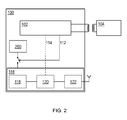
- FIG. 2 shows a system diagram of another embodiment of the invention.
- a wake-up signal 112 which is used to wake up the host processor 116 .
- the power supply of the host processor 116 is disabled in the inactive state and the wake-up signal 112 pulls a switch, for example a galvanic switch or a MOSFET switch, to connect a power source 200 to the host processor 116 such that the host processor 116 receives power and enters into the active state.
- a switch for example a galvanic switch or a MOSFET switch
- FIG. 3 shows a system diagram of a further embodiment of the invention.
- the host processor 116 is capable of one or more low-power modes.
- NXP Semiconductors' product family LPC11xxL has a so-called Deep-Sleep and a Deep-Power-Down mode in which a current of 2 ⁇ A and 220 nA, respectively, is drawn from the power supply.
- the typical operating current in an active state is at least three orders of magnitude higher than that at a few mA.
- the wake-up signal 112 is provided as a trigger signal on one of the pins, for example a PIO-pin or wake-up pin, of the host processor 116 .
- the host processor 116 When the host processor 116 receives the trigger signal on one of these pins it will move from a low-power mode to the active state.
- the selected power mode determines which internal blocks of the host processor 116 are switched off and which remain operational. Furthermore, the selected power mode determines the extent to which data can be retained in the host memory 118 .
- FIG. 3 is a refinement of the embodiment of FIG. 2 in the sense that it enables that different internal blocks of the host processor 116 can be switched off independently or switched to a mode with less functionality and less power consumption, whereas the embodiment of FIG. 2 merely enables to switch off the host processor 116 completely.
- additional logic (not shown) is available to wake up the internal blocks in the correct order when the wake-up signal 112 is received.
- FIG. 4 shows a system diagram of a further embodiment of the invention. In particular, it shows how a wake-up signal can be generated for waking up the host processor 116 .
- an RFID reader unit provides power to a passive RFID tag through inductive coupling.
- Data communication between the RFID reader unit and the RFID tag is established through load modulation.
- a protocol for address resolution is provided for selecting a particular RFID tag for further interaction in case multiple RFID tags are present in the electromagnetic field generated by the RFID reader unit.
- a typical interaction involves reading and/or writing data from/to a memory unit comprised in the RFID tag.
- the RFID tag usually comprises a tag controller, for example a microcontroller, which is arranged to control these operations.
- the tag controller 110 sends a wake-up signal 112 to the host processor 116 upon detecting an electromagnetic field generated by the second device 104 .
- the tag controller 110 is able to detect the presence of an electromagnetic field via the RFID interface 108 .
- the tag controller 110 also knows whether or not this presence is intentional, i.e. whether the RFID reader unit that generates the field has indeed selected the particular RFID tag for the communication. If the presence of a field is detected and the presence is intentional in the aforementioned meaning, then the tag controller 110 will send the wake-up signal 112 to the host processor 116 .
- the tag controller 110 may be arranged to send the wake-up signal 112 only if data are read from and/or written to the tag memory 106 , or, more specifically, only if data are read from and/or written to predetermined areas of the tag memory 106 .
- the conditions that determine whether or not a wake-up signal 112 is generated may be reconfigurable.
- Re-configurability can be achieved as follows.
- the second device 104 may write configuration parameters into a dedicated area of the tag memory 106 .
- re-configurability can be achieved by the host processor 116 writing configuration parameters into said dedicated area by means of the optional host connection 114 .
- the tag controller 110 will interpret the configuration parameters to decide whether or not to trigger the wake-up signal 112 .
- a prior-art RFID tag is implemented as a single Integrated Circuit (IC) with no leads being connected to it other than the RFID antenna coil.
- IC Integrated Circuit
- the tag controller 110 In order to have the tag controller 110 provide a wake-up signal 112 a new IC needs to be designed and fabricated.
- FIG. 5 shows a system diagram of yet a further embodiment of the invention.
- a dedicated wake-up circuit or field detector 500 must be added next to the prior art IC.
- this wake-up circuit 500 has its own antenna coil. Clearly, this antenna coil must be mounted in very close proximity to the RFID tag's antenna. Only then both antennas will be powered simultaneously when the second device 104 is in close proximity to them.
- the wake-up signal 112 in this embodiment is only indicative of the presence of a field. It does not indicate whether a second device 104 actually interacts with the RFID tag 102 , i.e. it does not indicate whether this particular RFID tag 102 is selected for communication by the second device 104 .
- the host processor 116 preferably will check whether an actual interaction has taken place with the RFID tag 102 , e.g. by verifying whether a particular memory location has been written to, before e.g. proceeding with a certain commissioning operation such as establishing a network connection and/or establishing a control relationship.
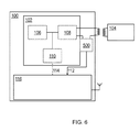
- FIG. 6 shows a system diagram of a further embodiment of the invention. In particular, it shows a refinement of the embodiment described with reference to FIG. 5 .
- This embodiment also has a separate wake-up circuit 500 , but in this case the wake-up circuit 500 shares an antenna coil with the RFID tag 102 . This embodiment reduces cost and it makes sure that the RFID tag 102 and the wake-up circuit 500 both detect the same field.
- FIG. 7 shows a system diagram of a further embodiment of the invention.
- a tag selection detector 700 capable of detecting whether the RFID tag 102 continues interacting for a longer period of time after an initial field is detected in its antenna coil.
- a tag selection detector 700 capable of detecting whether the RFID tag 102 continues interacting for a longer period of time after an initial field is detected in its antenna coil.
- the tag selection detector 700 is arranged to detect whether such continued (load) modulation takes place in the antenna coil of the RFID tag 102 and only if this is the case it will send the wake-up signal 112 to the host processor 116 .
- the advantage of this further embodiment is that the host processor 116 will only be woken up if its RFID tag 102 is actually selected by the RFID reader unit and not just by the fact that a field is present in its coil. This avoids unnecessary wake-ups of the host processor 116 and therefore unnecessary power consumption by the host processor 116 . Furthermore, the host processor 116 does not have to check whether an actual interaction has taken place with the RFID tag (as in the embodiment described with reference to FIG. 5 ). This means, for example, that it is not necessary for the RFID reader unit to write data to the RFID tag 102 only in order for the host processor 116 to know whether or not an actual interaction has taken place. Such additional writing of data is a drawback because it may break backward compatibility of a prior art commissioning procedure.
- the RFID tag 102 may be used to exchange configuration data such as contact data which enable the second device 104 to integrate the first device 100 into an existing network, for example, or to establish a network connection between the first device 100 and itself. Furthermore, commissioning may, for example, involve establishing a control relationship between the first device 100 and the second device 104 . To this end, the RFID tag 102 may be used to exchange further configuration data. After waking up, the host processor 116 of the first device 100 will engage in out-of-band (i.e. RFID) communication and/or in-band (i.e. longer range like RF) communication with the second device 104 .
- out-of-band i.e. RFID
- in-band i.e. longer range like RF
- An exemplary method of commissioning a first device 100 in accordance with the invention comprises the following steps. First, an end-user brings a second device 104 in close proximity of the (RFID tag 102 of the) first device 100 with the intent to integrate the first device 100 into a network administered by (or via) the second device 104 . Note that in accordance with the invention the first device 100 does not have to be powered for this.
- the RFID reader unit of the second device 104 interacts with the first device 100 which results in two simultaneous actions: (1) the RFID tag 102 of the first device 100 raises the wake-up signal 112 according to the invention in order to wake up the host processor 116 of the first device 100 , and subsequently the host processor 116 powers up its interface unit 122 and starts listening for a message; (2) the RFID reader unit of the second device 104 reads out certain contact data from the RFID tag 102 of the first device 100 , for example a Media Access Control (MAC) address and a public key belonging to the first device 100 . Subsequently, the second device 104 obtains network parameters belonging to the network to be joined, e.g. as stored in its internal memory. For example, a network ID (e.g.
- the second device 104 encrypts those network parameters with the public key belonging to the first device 100 and subsequently sends a message with this encrypted data over a radio interface unit addressed to the interface unit 122 of the first device 100 by utilizing the MAC-address of the first device 100 .
- the first device 100 receives the message sent by the second device 104 and decrypts it with the private key corresponding to the public key, i.e. the private key of the public/private key pair. Then, the first device 100 utilizes the network parameters (network ID and network key) to connect to the network. This may involve further interactions over the (in-band) network and as a result the first device 100 may obtain a (dynamically assigned) network address.
- the first device 100 sends a message to the second device 104 in order to establish a control relationship with the second device 104 .
- the dynamically assigned network address of the first device 100 may be part of this message.
- the control relationship may involve streaming audio data.
- the second device 104 may use the dynamic network address of the first device 100 in a subsequent step to associate it with a third device, for example a smart lamp that will control its light level based upon the light level measured by the wireless sensor node.
- any reference sign placed between parentheses shall not be construed as limiting the claim.
- the word “comprise(s)” or “comprising” does not exclude the presence of elements or steps other than those listed in a claim.
- the word “a” or “an” preceding an element does not exclude the presence of a plurality of such elements.
- the invention may be implemented by means of hardware comprising several distinct elements and/or by means of a suitably programmed processor. In a device claim enumerating several means, several of these means may be embodied by one and the same item of hardware.
- the mere fact that certain measures are recited in mutually different dependent claims does not indicate that a combination of these measures cannot be used to advantage.
Abstract
According to an aspect of the invention a system for commissioning devices is provided, which system comprises: a first device and a second device; an RFID tag comprised in the first device; a host processor comprised in the first device; wherein the second device is arranged to generate an electromagnetic field; wherein the RFID tag is arranged to detect the electromagnetic field and to wake up the host processor upon detecting said electromagnetic field in order for the second device to communicate with the host processor. Furthermore, a corresponding method for commissioning devices is provided. Since the RFID tag comprised in the first device is arranged to wake up the host processor, an end-user does not have to switch on the first device manually. Therefore, the user interaction is simplified. Furthermore, there is no need for a separate power button on the first device. The latter reduces cost and simplifies the design of the first device.
Description
This application claims the priority under 35 U.S.C. §119 of European patent application no. 11182503.0, filed on Sep. 23, 2011, the contents of which are incorporated by reference herein.
The invention relates to a system for commissioning devices. The invention also relates to a method for commissioning devices.
Radio frequency identification technology (RFID) and, more specifically, near field communication technology (NFC), have proven to be of particular value for setting up Wi-Fi networks and for pairing Bluetooth devices. Furthermore, these technologies can be of high value in the field of smart buildings. For example, they can be used to simplify the commissioning of wireless devices in a smart building.
In this context, the term “commissioning” is used to refer to operations that relate to the configuration of devices, such as establishing a network connection between devices, establishing a control relationship between devices and localizing devices in an environment.
In a typical commissioning procedure two wireless devices are brought in close proximity of each other or in direct contact with each other. Subsequently, these devices establish a secure network connection and/or a control relationship between each other. Network parameters, including encryption keys, are exchanged over a very short distance which makes eavesdropping difficult. NFC technology, which typically requires distances of a few centimeters, provides a particular advantage in this respect. Another advantage of NFC technology is the so-called ease-of-install; NFC technology makes commissioning procedures easy and intuitive to perform and it reduces the error-proneness of these procedures.
As a result, the Wi-Fi Alliance (http://www.wi-fi.org/) has standardized NFC as optional means for Wi-Fi Simple Configuration (WSC), formerly known as Wi-Fi Protected Setup (WPS). This has been described in the document “Wi-Fi Simple Configuration, Technical Specification”, version 2.0.0, December 2010 by the Wi-Fi Alliance.
In accordance with this known commissioning procedure an RFID tag is physically attached to the housing of a first wireless device. The RFID tag contains contact data of the first wireless device, such as its Media Access Control (MAC) address. In order to integrate the first wireless device into a Wi-Fi network, a second wireless device is equipped with an RFID reader unit. The second wireless device is brought into close proximity of the first wireless device in order to enable the RFID reader unit to read out the contact data of the first wireless device from the RFID tag. Then, the second wireless device may use the contact data in so-called in-band communication over the Wi-Fi network in order to integrate the first wireless device in a secure manner into the network.
In a similar way Bluetooth Easy Pairing enables establishing a secure Bluetooth connection between two devices, for example a phone and a headset. In this case not only a network connection is set up, but also a control relationship is established. For example, the audio stream from the phone may be routed to the headset and the headset may transmit commands back to the phone.
Both the Wi-Fi and the Bluetooth examples are based on RFID technology, in particular NFC technology. Specific details of the NFC communication involved have been described in the document “Connection Handover, Technical Specification” by the NFC Forum, version 1.2, July 2010 (http://www.nfc-forum.org/).
Another example of the use of RFID/NFC technology to establish a control relationship between devices is described in patent application WO 2010/032227 A1, filed by NXP Semiconductors and published on 25 Mar. 2010.
WO 2010/032227 A1 discloses a method for controlling controllable devices, such as lamp units that are installed in a building, with a plurality of control interface units, such as light switches. Each control interface unit has a receptor, such as a light switch, for receiving user actuations. Addresses to be used for selective transmission of messages to controllable devices are established by enabling the control interface unit that should control a controllable device to read a tag on or in the controllable device. The control interface units each have their own tag reader capable of reading the tag when the tag is in proximity of the control interface unit. The controllable devices are brought into the proximity of a selected one of the control interface units before installation of the controllable device, in order to indicate that the controllable device has to be controlled by actuation of a receptor of the selected one of the control interface units. The tag of the controllable device is read from the selected one of the control interface units. Information from the tag is automatically used to establish destinations to be used for messages from the selected one of the control interface units in response to future detection of user actuation of the receptor of the selected one of the control interface units. Subsequently, the controllable device may be installed in the building at a location outside said proximity.
Although these examples clearly show that RFID/NFC technology provides important advantages when it is used to commission wireless devices of the kind set forth, there are still a number of shortcomings which hinder large-scale deployment thereof. For example, a typical prior art procedure for connecting a Bluetooth headset with a Bluetooth-enabled mobile phone involves switching on the headset by pushing its power button and bringing it in close proximity of the phone. The procedure requires two end-user actions: (1) switching on the headset and (2) bringing the phone and the headset in close proximity of each other. It is essential that the headset is switched on before or while the phone is in close proximity of the headset; otherwise the procedure will fail. This procedure is not user-friendly and prone to errors. For instance, forgetting to switch on the headset before touching the phone is a mistake which is easily made. Therefore, a bad overall end-user experience may be the result. Furthermore, the headset needs to be equipped with a power button which increases its costs and limits the freedom to design it. It will be appreciated that the headset cannot stay powered all the time in view of the limited capacity of its battery, so it must be brought in a low-power or sleep mode when it is not in use.
A similar problem occurs when securely setting up a Wireless Sensor Network (WSN) comprising of wireless sensor nodes. Wireless sensor nodes are energy-frugal devices (having an average power consumption of less than 100 μW) that may extract the energy required for their operation from their environment. The extremely low average power consumption is achieved through duty cycling, i.e. the device wakes up, for example, every few minutes to perform some measurements and transmit a few tens of bytes and subsequently goes back to sleep. The total duration of the active period may be no more than a few milliseconds.
Wireless sensor nodes are able to configure themselves automatically in a WSN, but this procedure is not secure. For example, in home automation systems it is not possible to distinguish between sensor nodes belonging to one's own house and the neighbor's house. One would like to configure a network comprising the sensor nodes in one's own house, but not those in the neighboring houses. Furthermore, privacy and security present a problem. For example, one doesn't want one's presence to be inferred from wireless sensor messages, and one doesn't want someone to hack one's home automation system. Finally, although (unsecure) network joining may take place automatically, automation is less trivial for other aspects of commissioning such as establishing control relationships between devices and localization of devices.
Also in this case NFC-based “touching” enables easy and secure commissioning of a wireless sensor node. For example, an NFC-enabled installation device may be used to “touch” a sensor node which has an RFID tag attached to it in order to make it join the WSN in a secure manner, to establish a control relationship and/or to localize it. However, since the sensor node may only be in an active state once every few minutes it is necessary to explicitly force it to become active, for instance by pressing a button. Again, the button complicates the commissioning procedure and increases the cost of the sensor node. Furthermore, adding a button may be impractical in view of the small form factor of the sensor node. Also, the time span between a user pushing the button and subsequently bringing the installation device and the wireless sensor node in close proximity of each other (typically in the order of seconds) may already be too long considering the very limited energy resources of the wireless sensor node.
Therefore, there exists a need to simplify the procedures for commissioning devices of the kind set forth.
It is an object of the invention to simplify the procedures for commissioning devices of the kind set forth. This is achieved by a system as defined in claim 1 and by a method as defined in claim 9.
According to an aspect of the invention a system for commissioning devices is provided, which system comprises: a first device and a second device; an RFID tag comprised in the first device; a host processor comprised in the first device; wherein the second device is arranged to generate an electromagnetic field; wherein the RFID tag is arranged to detect the electromagnetic field and to wake up the host processor upon detecting said electromagnetic field in order for the second device to communicate with the host processor.
Since the RFID tag comprised in the first device is arranged to wake up the host processor, an end-user does not have to switch on the first device manually. Therefore, the user interaction is simplified. Furthermore, there is no need for a separate power button on the first device. The latter reduces cost and simplifies the design of the first device.
According to another aspect of the invention, the second device is arranged to read out configuration data comprised in the RFID tag and to use said configuration data to commission the first device.
According to a further aspect of the invention, the configuration data comprise contact data and the second device is arranged to use said contact data for establishing a network connection with the first device.
According to a further aspect of the invention, the host processor comprises an interface unit and the second device is arranged to establish the network connection with the first device via the interface unit.
According to a further aspect of the invention, the RFID tag comprises a tag controller which is arranged to send a wake-up signal to the host processor in order to wake up the host processor.
According to a further aspect of the invention, the tag controller is further arranged to send the wake-up signal only if data are read from and/or written to the tag memory or if data are read from and/or written to predetermined areas of the tag memory.
According to a further aspect of the invention, the first device is a Bluetooth headset and the second device is a Bluetooth-enabled mobile phone. An advantage of using the invention in combination with a known method of pairing Bluetooth devices, such as Bluetooth Easy Pairing, is that it is backward compatible. This means that a new headset can be manufactured without a power button and it still works seamlessly with any Bluetooth Easy Pairing enabled phone.
According to a further aspect of the invention, the network is a wireless sensor network, the first device is a wireless sensor node and the second device is arranged to commission the wireless sensor node.
According to an aspect of the invention, a method for commissioning a first device and a second device is provided, which method comprises that an RFID tag comprised in the first device wakes up a host processor comprised in the first device upon detecting an electromagnetic field generated by the second device, in order for the second device to communicate with the host processor.
According to another aspect of the invention, the second device reads out configuration data comprised in the RFID tag and uses said configuration data to commission the first device.
According to a further aspect of the invention, the configuration data comprise contact data and the second device uses said contact data for establishing a network connection with the first device.
According to a further aspect of the invention, the contact data comprise a Media Access Control (MAC) address and a public key.
According to a further aspect of the invention, the second device encrypts network parameters with the public key and subsequently sends the encrypted network parameters to the host processor utilizing the Media Access Control address, and the host processor receives the encrypted network parameters and subsequently decrypts the encrypted network parameters with a private key corresponding to the public key.
According to a further aspect of the invention, the host processor uses the decrypted network parameters for establishing the network connection.
According to a further aspect of the invention, subsequent to establishing the network connection, the first device sends a message to the second device for initiating a control relationship between the first device and the second device.
The invention will be described in more detail with reference to the appended drawings, in which:
In operation, the second device 104 interacts, via its RFID reader unit, with the RFID tag 102 of the first device 100. The second device 104 may for example read out data (such as a MAC address of the first device 100) from the tag memory 106. Alternatively the second device 104 may write data into the tag memory 106. When such an interaction takes place the RFID tag 102 activates and sends a wake-up signal 112 to wake up the host processor 116. The RFID tag 102 may be a passive tag, which means that it has no built-in power source. In that case, the RFID reader unit of the second device 104 wirelessly supplies operating power to the RFID tag through magnetic induction. Optionally, the tag controller 110 may have a data connection 114 with the host controller 120.
In an exemplary embodiment of the invention the first device 100 is a Bluetooth headset. The Bluetooth headset comprises headset speakers (not shown) and the interface unit 122 of the host processor 116 is a Bluetooth radio. In this exemplary embodiment the second device 104 is a mobile phone which is also equipped with a Bluetooth radio (not shown). In operation, the mobile phone reads out data from the RFID tag of the headset in order to establish a connection with the headset. After this network connection between the headset and the mobile phone has been established, a control relationship may also be established between them.
In another exemplary embodiment the first device 100 is a wireless sensor node and the interface unit 122 of the host processor 116 is an Ultra Low Power radio, for example an IEEE 802.15.4 radio. In this exemplary embodiment the second device is an NFC-enabled installation device which, again, may be a mobile phone, a personal digital assistant (PDA) or a portable computer. In operation, the installation device commissions the wireless sensor node by integrating it into a wireless sensor network.
The wake-up signal 112 is used to cause the host processor 116 of the first device 100 to move from an inactive state to an active state when the second device 104 interacts with the RFID tag 102 of the first device 100. The inactive state may be a low-power mode, a sleep mode or any other mode in which the power usage is significantly lower than in the active state.
The embodiment of FIG. 3 is a refinement of the embodiment of FIG. 2 in the sense that it enables that different internal blocks of the host processor 116 can be switched off independently or switched to a mode with less functionality and less power consumption, whereas the embodiment of FIG. 2 merely enables to switch off the host processor 116 completely. In the embodiment of FIG. 3 additional logic (not shown) is available to wake up the internal blocks in the correct order when the wake-up signal 112 is received.
In a typical RFID system an RFID reader unit provides power to a passive RFID tag through inductive coupling. Data communication between the RFID reader unit and the RFID tag is established through load modulation. Typically, a protocol for address resolution is provided for selecting a particular RFID tag for further interaction in case multiple RFID tags are present in the electromagnetic field generated by the RFID reader unit. Furthermore, a typical interaction involves reading and/or writing data from/to a memory unit comprised in the RFID tag. The RFID tag usually comprises a tag controller, for example a microcontroller, which is arranged to control these operations.
According to an exemplary embodiment of the invention the tag controller 110 sends a wake-up signal 112 to the host processor 116 upon detecting an electromagnetic field generated by the second device 104. The tag controller 110 is able to detect the presence of an electromagnetic field via the RFID interface 108. Furthermore, the tag controller 110 also knows whether or not this presence is intentional, i.e. whether the RFID reader unit that generates the field has indeed selected the particular RFID tag for the communication. If the presence of a field is detected and the presence is intentional in the aforementioned meaning, then the tag controller 110 will send the wake-up signal 112 to the host processor 116.
Optionally, the tag controller 110 may be arranged to send the wake-up signal 112 only if data are read from and/or written to the tag memory 106, or, more specifically, only if data are read from and/or written to predetermined areas of the tag memory 106.
Furthermore, the conditions that determine whether or not a wake-up signal 112 is generated may be reconfigurable. Re-configurability can be achieved as follows. The second device 104 may write configuration parameters into a dedicated area of the tag memory 106. Alternatively, or additionally, re-configurability can be achieved by the host processor 116 writing configuration parameters into said dedicated area by means of the optional host connection 114. The tag controller 110 will interpret the configuration parameters to decide whether or not to trigger the wake-up signal 112.
Typically, a prior-art RFID tag is implemented as a single Integrated Circuit (IC) with no leads being connected to it other than the RFID antenna coil. In order to have the tag controller 110 provide a wake-up signal 112 a new IC needs to be designed and fabricated.
However, instead of designing and fabricating an RFID tag IC capable of generating and sending a wake-up signal, a prior-art RFID tag IC can be used which is extended with a dedicated wake-up circuit. This is illustrated in FIG. 5 , which shows a system diagram of yet a further embodiment of the invention. In this case, a dedicated wake-up circuit or field detector 500 must be added next to the prior art IC. In its most simple form this wake-up circuit 500 has its own antenna coil. Clearly, this antenna coil must be mounted in very close proximity to the RFID tag's antenna. Only then both antennas will be powered simultaneously when the second device 104 is in close proximity to them.
The skilled person will recognize that the wake-up signal 112 in this embodiment is only indicative of the presence of a field. It does not indicate whether a second device 104 actually interacts with the RFID tag 102, i.e. it does not indicate whether this particular RFID tag 102 is selected for communication by the second device 104. This means that the host processor 116 preferably will check whether an actual interaction has taken place with the RFID tag 102, e.g. by verifying whether a particular memory location has been written to, before e.g. proceeding with a certain commissioning operation such as establishing a network connection and/or establishing a control relationship.
The advantage of this further embodiment is that the host processor 116 will only be woken up if its RFID tag 102 is actually selected by the RFID reader unit and not just by the fact that a field is present in its coil. This avoids unnecessary wake-ups of the host processor 116 and therefore unnecessary power consumption by the host processor 116. Furthermore, the host processor 116 does not have to check whether an actual interaction has taken place with the RFID tag (as in the embodiment described with reference to FIG. 5 ). This means, for example, that it is not necessary for the RFID reader unit to write data to the RFID tag 102 only in order for the host processor 116 to know whether or not an actual interaction has taken place. Such additional writing of data is a drawback because it may break backward compatibility of a prior art commissioning procedure.
An important aspect of commissioning devices is establishing a network connection. The RFID tag 102 may be used to exchange configuration data such as contact data which enable the second device 104 to integrate the first device 100 into an existing network, for example, or to establish a network connection between the first device 100 and itself. Furthermore, commissioning may, for example, involve establishing a control relationship between the first device 100 and the second device 104. To this end, the RFID tag 102 may be used to exchange further configuration data. After waking up, the host processor 116 of the first device 100 will engage in out-of-band (i.e. RFID) communication and/or in-band (i.e. longer range like RF) communication with the second device 104.
An exemplary method of commissioning a first device 100 in accordance with the invention comprises the following steps. First, an end-user brings a second device 104 in close proximity of the (RFID tag 102 of the) first device 100 with the intent to integrate the first device 100 into a network administered by (or via) the second device 104. Note that in accordance with the invention the first device 100 does not have to be powered for this.
Second, the RFID reader unit of the second device 104 interacts with the first device 100 which results in two simultaneous actions: (1) the RFID tag 102 of the first device 100 raises the wake-up signal 112 according to the invention in order to wake up the host processor 116 of the first device 100, and subsequently the host processor 116 powers up its interface unit 122 and starts listening for a message; (2) the RFID reader unit of the second device 104 reads out certain contact data from the RFID tag 102 of the first device 100, for example a Media Access Control (MAC) address and a public key belonging to the first device 100. Subsequently, the second device 104 obtains network parameters belonging to the network to be joined, e.g. as stored in its internal memory. For example, a network ID (e.g. SSID for Wi-Fi network) and a network key (e.g. WPA2-key for a Wi-Fi network). Then, the second device 104 encrypts those network parameters with the public key belonging to the first device 100 and subsequently sends a message with this encrypted data over a radio interface unit addressed to the interface unit 122 of the first device 100 by utilizing the MAC-address of the first device 100.
Third, the first device 100 receives the message sent by the second device 104 and decrypts it with the private key corresponding to the public key, i.e. the private key of the public/private key pair. Then, the first device 100 utilizes the network parameters (network ID and network key) to connect to the network. This may involve further interactions over the (in-band) network and as a result the first device 100 may obtain a (dynamically assigned) network address.
Optionally, the first device 100 sends a message to the second device 104 in order to establish a control relationship with the second device 104. The dynamically assigned network address of the first device 100 may be part of this message. For example, if the first device 100 is a Bluetooth headset and the second device 104 is a mobile phone, the control relationship may involve streaming audio data. Alternatively, if the first device 100 is a wireless sensor node which measures a light level and the second device 104 is an installation device, the second device 104 may use the dynamic network address of the first device 100 in a subsequent step to associate it with a third device, for example a smart lamp that will control its light level based upon the light level measured by the wireless sensor node.
It must be emphasized that the implementation details are merely examples. The skilled person will appreciate that other network establishment protocols, other sets of network parameters, other mechanisms for secure in-band exchange of network keys, other networking technologies, and other types of devices may be used in a method according to the invention.
The above-mentioned preferred embodiments illustrate rather than limit the invention, and the skilled person will be able to design many alternative embodiments without departing from the scope of the appended claims. In the claims, any reference sign placed between parentheses shall not be construed as limiting the claim. The word “comprise(s)” or “comprising” does not exclude the presence of elements or steps other than those listed in a claim. The word “a” or “an” preceding an element does not exclude the presence of a plurality of such elements. The invention may be implemented by means of hardware comprising several distinct elements and/or by means of a suitably programmed processor. In a device claim enumerating several means, several of these means may be embodied by one and the same item of hardware. The mere fact that certain measures are recited in mutually different dependent claims does not indicate that a combination of these measures cannot be used to advantage.
- 100 first device
- 102 RFID tag
- 104 second device
- 106 tag memory
- 108 RFID interface
- 110 tag controller
- 112 wake-up signal
- 114 optional host connection
- 116 host processor
- 118 host memory
- 120 host controller
- 122 interface unit
- 200 power source
- 500 wake-up circuit
- 700 tag selection detector
Claims (18)
1. A system for commissioning devices, the system comprising:
a first device comprising an RFID tag and a host processor;
a second device; wherein the second device is configured to generate an electromagnetic field, the RFID tag is configured to detect the electromagnetic field and wake up the host processor upon detecting said electromagnetic field in order for the second device to communicate with the host processor, the RFID tag comprises a tag controller which is configured to send a wake-up signal to the host processor in order to wake up the host processor only when data are read from and/or written to a predetermined area of memory; and
a separate wake-up circuit comprising a tag selection detector capable of detecting whether the RFID tag continues interacting for a longer period of time after an initial field is detected in the antenna coil.
2. The system as claimed in claim 1 , wherein the second device is configured to read out configuration data from the RFID tag and to use said configuration data to commission the first device.
3. The system as claimed in claim 2 , wherein the configuration data comprise contact data and the second device is configured to use said contact data for establishing a network connection with the first device.
4. The system as claimed in claim 3 , wherein the host processor comprises an interface unit and the second device is configured to establish the network connection with the first device via the interface unit.
5. The system as claimed in claim 1 , wherein the first device is a Bluetooth™ headset and the second device is a Bluetooth-enabled mobile phone.
6. The system as claimed in claim 1 , wherein the network is a wireless sensor network, the first device is a wireless sensor node, and the second device is configured to commission the wireless sensor node.
7. The system as claimed in claim 1 , wherein conditions that determine whether or not a wake-up signal is generated are reconfigurable.
8. The system as claimed in claim 7 , wherein the second device is configured to write configuration parameters into a dedicated area of the tag memory in order to reconfigure said conditions, and the host processor is configured to write configuration parameters into said dedicated area by means of a host connection in order to reconfigure said conditions.
9. The system as claimed in claim 1 , wherein the second device writes configuration parameters into a dedicated area of the tag memory in order to reconfigure said conditions, and the host processor writes configuration parameters into said dedicated area by means of a host connection in order to reconfigure said conditions.
10. A method for commissioning a first device comprising an RFID tag and a host processor and a second device, the method comprising:
detecting, with the RFID tag, an electromagnetic field generated by the second device;
waking up the host processor upon detecting an electromagnetic field in order for the second device to communicate with the host processor;
sending, with a tag controller in the RFID tag, a wake-up signal to the host processor in order to wake up the host processor only when data are read from and/or written to predetermined areas of a tag memory; and
detecting, with a tag selection detector, whether the RFID tag continues interacting for a longer period of time after an initial field is detected in the antenna coil.
11. The method as claimed in claim 10 , further comprising:
reading, with the second device, configuration data comprised in the RFID tag; and
using the configuration data to commission the first device.
12. The method as claimed in claim 11 , wherein the configuration data comprise contact data and wherein the second device uses said contact data for establishing a network connection with the first device.
13. The method as claimed in claim 12 , wherein the contact data comprise a Media Access Control (MAC) address and a public key.
14. The method as claimed in claim 13 , further comprising:
encrypting, with the second device, network parameters with the public key; and
sending the encrypted network parameters to the host processor utilizing the MAC address, wherein the host processor receives the encrypted network parameters and decrypts the network parameters with a private key corresponding to the public key.
15. The method as claimed in claim 14 , wherein the host processor uses the decrypted network parameters for establishing the network connection.
16. The method as claimed in claim 11 , wherein, subsequent to establishing the network connection, the first device sends a message to the second device for initiating a control relationship between the first device and the second device.
17. A system for commissioning devices, the system comprising:
a first device comprising an RFID tag and a host processor; and
a second device, wherein the second device is configured to generate an electromagnetic field, the RFID tag is configured to detect the electromagnetic field, wake up the host processor upon detecting said electromagnetic field in order for the second device to communicate with the host processor, and detect said electromagnetic field and wake up the host processor by means of a separate wake-up circuit, wherein the separate wake-up circuit comprises a tag selection detector capable of detecting whether the RFID tag continues interacting for a longer period of time after an initial field is detected in the antenna coil.
18. The system as claimed in claim 17 , wherein the separate wake-up circuit shares an antenna coil with the RFID tag.
Applications Claiming Priority (3)
| Application Number | Priority Date | Filing Date | Title |
|---|---|---|---|
| EP11182503 | 2011-09-23 | ||
| EP11182503.0 | 2011-09-23 | ||
| EP11182503.0A EP2573948B1 (en) | 2011-09-23 | 2011-09-23 | System and method for commissioning devices |
Publications (2)
| Publication Number | Publication Date |
|---|---|
| US20130076491A1 US20130076491A1 (en) | 2013-03-28 |
| US9762295B2 true US9762295B2 (en) | 2017-09-12 |
Family
ID=44862480
Family Applications (1)
| Application Number | Title | Priority Date | Filing Date |
|---|---|---|---|
| US13/622,936 Active 2034-06-05 US9762295B2 (en) | 2011-09-23 | 2012-09-19 | System and method for commissioning devices |
Country Status (3)
| Country | Link |
|---|---|
| US (1) | US9762295B2 (en) |
| EP (1) | EP2573948B1 (en) |
| CN (1) | CN103019100B (en) |
Cited By (4)
| Publication number | Priority date | Publication date | Assignee | Title |
|---|---|---|---|---|
| US20170127302A1 (en) * | 2014-06-18 | 2017-05-04 | Telefonaktiebolaget Lm Ericsson (Publ) | Methods and devices for maintaining a device-operated function |
| US10154018B2 (en) | 2015-02-19 | 2018-12-11 | Nxp B.V. | Method and system for facilitating network joining |
| US10660308B2 (en) | 2015-11-04 | 2020-05-26 | Delaval Holding Ab | System and method for imaging and processing animal data |
| US20210167817A1 (en) * | 2017-02-08 | 2021-06-03 | Canon Kabushiki Kaisha | Power transmission apparatus, power reception apparatus, method, and recording medium |
Families Citing this family (42)
| Publication number | Priority date | Publication date | Assignee | Title |
|---|---|---|---|---|
| EP2602677B1 (en) | 2011-12-05 | 2018-02-21 | Nxp B.V. | Localization method, computer program product and localization device |
| EP2624081B1 (en) | 2012-01-31 | 2018-01-10 | Nxp B.V. | Configuration method, configuration device, computer program product and control system |
| EP2626755B1 (en) | 2012-02-10 | 2019-04-10 | Nxp B.V. | Calibration method, calibration device and measurement device |
| US9198204B2 (en) | 2012-04-11 | 2015-11-24 | Google Inc. | Apparatus and method for seamless commissioning of wireless devices |
| US10075334B1 (en) | 2012-04-11 | 2018-09-11 | Google Llc | Systems and methods for commissioning a smart hub device |
| US10142122B1 (en) | 2012-04-11 | 2018-11-27 | Google Llc | User interfaces, systems and methods for configuring smart devices for interoperability with a smart hub device |
| US10397013B1 (en) | 2012-04-11 | 2019-08-27 | Google Llc | User interfaces, systems and methods for configuring smart devices for interoperability with a smart hub device |
| EP2650820B1 (en) | 2012-04-12 | 2014-10-08 | Nxp B.V. | Control method and computer program product |
| EP2665235B1 (en) * | 2012-05-15 | 2016-01-06 | Nxp B.V. | Method for establishing secure communication between nodes in a network, network node, key manager, installation device and computer program product |
| EP2704365B1 (en) | 2012-08-31 | 2016-02-03 | Nxp B.V. | Method for establishing control relationships, configuration device, networked device and computer program product |
| US9716530B2 (en) * | 2013-01-07 | 2017-07-25 | Samsung Electronics Co., Ltd. | Home automation using near field communication |
| US9922580B2 (en) | 2013-04-30 | 2018-03-20 | Google Llc | Apparatus and method for the virtual demonstration of a smart phone controlled smart home using a website |
| GB2514158A (en) * | 2013-05-16 | 2014-11-19 | Ibm | Remotely awakening an electronic device |
| US9413463B2 (en) | 2013-08-30 | 2016-08-09 | Google Inc. | Apparatus and method for efficient two-way optical communication where transmitter may interfere with receiver |
| EP2858259B1 (en) * | 2013-10-07 | 2019-06-26 | Nxp B.V. | NFC tag, communication method and system |
| KR102143441B1 (en) * | 2013-11-15 | 2020-08-11 | 삼성전자주식회사 | Electronic device and method for updating authentication information in electronic device |
| US10088818B1 (en) | 2013-12-23 | 2018-10-02 | Google Llc | Systems and methods for programming and controlling devices with sensor data and learning |
| US9332103B2 (en) * | 2014-01-23 | 2016-05-03 | Harris Corporation | User protection in a multimode personal communication device |
| CN104809494B (en) * | 2014-01-28 | 2019-04-30 | 上海复旦微电子集团股份有限公司 | Label assembly, the method and electronic system that burning is carried out to label assembly |
| CN104811330A (en) * | 2014-01-28 | 2015-07-29 | 上海复旦微电子集团股份有限公司 | Network device and configuration method thereof, electronic device, router and mobile terminal |
| US10033435B2 (en) * | 2014-06-26 | 2018-07-24 | Intel IP Corporation | Apparatus, system and method of detecting an activity of a wireless communication device |
| US9544636B2 (en) | 2014-07-07 | 2017-01-10 | Google Inc. | Method and system for editing event categories |
| US10601604B2 (en) | 2014-11-12 | 2020-03-24 | Google Llc | Data processing systems and methods for smart hub devices |
| EP3086585B1 (en) | 2015-04-23 | 2019-12-11 | Nxp B.V. | Method and system for securing data communicated in a network |
| DE102015107478A1 (en) * | 2015-05-12 | 2016-11-17 | Harting Ag & Co. Kg | Sensor network and procedures for its operation |
| WO2017078600A1 (en) * | 2015-11-04 | 2017-05-11 | Delaval Holding Ab | System and method for imaging and processing animal data |
| US20170176963A1 (en) * | 2015-12-21 | 2017-06-22 | Carrier Corporation | Method for setting user preferences |
| FR3049796B1 (en) * | 2016-03-30 | 2018-04-27 | Sagemcom Energy & Telecom Sas | METHOD FOR ACTIVATING A CONNECTED OBJECT |
| ITUA20162411A1 (en) * | 2016-04-08 | 2017-10-08 | Berbrand S R L Unipersonale | METHOD AND AUTHENTICATION SYSTEM TO VERIFY THE AUTHORITY OF A PRODUCT |
| WO2018120039A1 (en) * | 2016-12-30 | 2018-07-05 | 深圳市大疆灵眸科技有限公司 | Automatic pairing method and device |
| EP3386149A1 (en) | 2017-04-07 | 2018-10-10 | IMEC vzw | Combined active and passive wireless communication device |
| DE102017109631A1 (en) * | 2017-05-04 | 2018-11-08 | Huf Hülsbeck & Fürst Gmbh & Co. Kg | Tire pressure sensor and use of a tire pressure sensor |
| JP2018207257A (en) * | 2017-06-01 | 2018-12-27 | 東芝テック株式会社 | Radio communication equipment, host terminal, and radio communication system |
| US10890345B2 (en) * | 2017-08-09 | 2021-01-12 | Verdigris Technologies, Inc. | System and methods for a commissioning a sensor system |
| EP3451543A1 (en) * | 2017-08-30 | 2019-03-06 | Nxp B.V. | Nfc device and power management method |
| JP7155581B2 (en) * | 2018-03-30 | 2022-10-19 | ブラザー工業株式会社 | Communication device and computer program for the communication device |
| US10820396B2 (en) * | 2018-05-03 | 2020-10-27 | RAB Lighting Inc. | Illumination control systems and methods |
| CN108845661B (en) * | 2018-06-12 | 2020-08-07 | 新华三技术有限公司 | Equipment control method and device |
| EP3598805A1 (en) * | 2018-07-16 | 2020-01-22 | ABB Schweiz AG | Apparatus for configuration of a sensor |
| US11265518B2 (en) * | 2019-09-03 | 2022-03-01 | BOB Profit Partners LLC | Camera system monitor for shopping cart bottom shelf |
| US11099402B2 (en) * | 2019-10-25 | 2021-08-24 | Microsoft Technology Licensing, Llc | Dynamically changing a fiducial marker for IoT device identification |
| US11822997B2 (en) * | 2019-12-18 | 2023-11-21 | Zebra Technologies Corporation | Methods and apparatus for multi-stage activation of communication devices |
Citations (32)
| Publication number | Priority date | Publication date | Assignee | Title |
|---|---|---|---|---|
| WO2006054070A1 (en) | 2004-11-18 | 2006-05-26 | Innovision Research & Technology Plc | Wireless communicators |
| WO2006116168A2 (en) | 2005-04-21 | 2006-11-02 | Univeristy Of Pittsburgh-Of The Commonwealth System Of Higher Education | Methods and apparatus for reducing power consumption of an active transponder |
| US20060258289A1 (en) * | 2005-05-12 | 2006-11-16 | Robin Dua | Wireless media system and player and method of operation |
| WO2007076191A2 (en) | 2005-11-23 | 2007-07-05 | University Of Pittsburgh - Of The Commonwealth System Of Higher Education | Methods and apparatus for reducing power consumption of an active transponder |
| US7250695B2 (en) * | 2003-10-31 | 2007-07-31 | Hewlett-Packard Development Company, L.P. | Controlling power supplied to a circuit using an externally applied magnetic field |
| US20070202807A1 (en) | 2006-02-08 | 2007-08-30 | Samsung Electronics Co., Ltd. | Bluetooth® system and Bluetooth® bonding process |
| WO2007101080A2 (en) | 2006-02-23 | 2007-09-07 | University Of Pittsburgh-Of The Commonwealth System Of Higher Education | Methods and apparatus for switching a transponder to an active state, and asset management systems employing same |
| CN101128839A (en) | 2005-03-30 | 2008-02-20 | 三星电子株式会社 | RF-ID tag reading system for using password and method thereof |
| US20080090520A1 (en) | 2006-10-17 | 2008-04-17 | Camp William O | Apparatus and methods for communication mobility management using near-field communications |
| WO2008059460A2 (en) | 2006-11-15 | 2008-05-22 | Nxp B.V. | Near field communication (nfc) activation |
| US20080143487A1 (en) * | 2006-12-19 | 2008-06-19 | Broadcom Corporation | System and method for enabling interrupts for rfid tags |
| US7412230B2 (en) | 2002-03-14 | 2008-08-12 | Holger Kunkat | Method of releasing communication between at least two communication devices |
| WO2009044228A2 (en) | 2006-08-15 | 2009-04-09 | Nxp B.V. | Device with an eeprom having both a near field communication interface and a second interface |
| WO2009104131A1 (en) | 2008-02-19 | 2009-08-27 | Nxp B.V. | System and method for entering a pairing mode without user intervention |
| WO2009128032A1 (en) | 2008-04-15 | 2009-10-22 | Nxp B.V. | Low power near-field communication devices |
| WO2009131381A2 (en) | 2008-04-22 | 2009-10-29 | Electronics And Telecommunications Research Institute | Rfid reader, rfid tag, and controlling method thereof |
| US20090298555A1 (en) * | 2004-03-26 | 2009-12-03 | Broadcom Corporation | MAC controlled sleep mode/wake-up mode with staged wake-up for power management devices |
| WO2010032227A1 (en) | 2008-09-22 | 2010-03-25 | Nxp B.V. | Automatic address selection for controllable devices |
| US20100231407A1 (en) * | 2009-03-13 | 2010-09-16 | New Jersey Microsystems, Inc. | RFID power control and monitoring system |
| US20100318693A1 (en) | 2009-06-11 | 2010-12-16 | Espig Michael J | Delegating A Poll Operation To Another Device |
| WO2011017007A1 (en) | 2009-08-03 | 2011-02-10 | Motorola, Inc. | Method and system for near-field wireless device pairing |
| WO2011035411A1 (en) | 2009-09-24 | 2011-03-31 | Research In Motion Limited | Accelerometer tap detection to initiate nfc communication |
| WO2011035414A1 (en) | 2009-09-24 | 2011-03-31 | Research In Motion Limited | Mobile wireless communications device, method and system using magnetic sensor and activated nfc circuit for establishing communications between mobile wireless communications devices |
| WO2011035413A1 (en) | 2009-09-24 | 2011-03-31 | Research In Motion Limited | System and associated nfc tag using plurality of nfc tags associated with location or devices to communicate with communications device |
| WO2011035412A1 (en) | 2009-09-24 | 2011-03-31 | Research In Motion Limited | Communications device and method for initiating communications at a communications device |
| CN102129596A (en) | 2011-03-07 | 2011-07-20 | 中国人民解放军总后勤部建筑工程研究所 | Active radio-frequency label and operating mode switching method thereof |
| WO2011097116A2 (en) | 2010-02-04 | 2011-08-11 | Carefusion 303, Inc. | Inventory control device |
| US20110210831A1 (en) | 2010-02-26 | 2011-09-01 | Gm Global Technology Operations, Inc. | Simplified device pairing employing near field communication tags |
| US20130002398A1 (en) * | 2011-07-01 | 2013-01-03 | Brown David A | Apparatus, System, and Method for Providing Attribute Identity Control Associated with a Processor |
| US20130198813A1 (en) | 2012-01-31 | 2013-08-01 | Nxp B.V. | Configuration method, configuration device, computer program product and control system |
| US20130211761A1 (en) | 2012-02-10 | 2013-08-15 | Nxp B.V. | Calibration method, calibration device and measurement device |
| US20140068089A1 (en) | 2012-08-31 | 2014-03-06 | Nxp B.V. | Method of establishing control relationships, configuration device, networked device and computer program product |
-
2011
- 2011-09-23 EP EP11182503.0A patent/EP2573948B1/en active Active
-
2012
- 2012-09-18 CN CN201210347734.8A patent/CN103019100B/en active Active
- 2012-09-19 US US13/622,936 patent/US9762295B2/en active Active
Patent Citations (33)
| Publication number | Priority date | Publication date | Assignee | Title |
|---|---|---|---|---|
| US7412230B2 (en) | 2002-03-14 | 2008-08-12 | Holger Kunkat | Method of releasing communication between at least two communication devices |
| US7250695B2 (en) * | 2003-10-31 | 2007-07-31 | Hewlett-Packard Development Company, L.P. | Controlling power supplied to a circuit using an externally applied magnetic field |
| US20090298555A1 (en) * | 2004-03-26 | 2009-12-03 | Broadcom Corporation | MAC controlled sleep mode/wake-up mode with staged wake-up for power management devices |
| WO2006054070A1 (en) | 2004-11-18 | 2006-05-26 | Innovision Research & Technology Plc | Wireless communicators |
| CN101128839A (en) | 2005-03-30 | 2008-02-20 | 三星电子株式会社 | RF-ID tag reading system for using password and method thereof |
| US8203449B2 (en) | 2005-03-30 | 2012-06-19 | Samsung Electronics Co., Ltd. | RF-ID tag reading system for using password and method thereof |
| WO2006116168A2 (en) | 2005-04-21 | 2006-11-02 | Univeristy Of Pittsburgh-Of The Commonwealth System Of Higher Education | Methods and apparatus for reducing power consumption of an active transponder |
| US20060258289A1 (en) * | 2005-05-12 | 2006-11-16 | Robin Dua | Wireless media system and player and method of operation |
| WO2007076191A2 (en) | 2005-11-23 | 2007-07-05 | University Of Pittsburgh - Of The Commonwealth System Of Higher Education | Methods and apparatus for reducing power consumption of an active transponder |
| US20070202807A1 (en) | 2006-02-08 | 2007-08-30 | Samsung Electronics Co., Ltd. | Bluetooth® system and Bluetooth® bonding process |
| WO2007101080A2 (en) | 2006-02-23 | 2007-09-07 | University Of Pittsburgh-Of The Commonwealth System Of Higher Education | Methods and apparatus for switching a transponder to an active state, and asset management systems employing same |
| WO2009044228A2 (en) | 2006-08-15 | 2009-04-09 | Nxp B.V. | Device with an eeprom having both a near field communication interface and a second interface |
| US20080090520A1 (en) | 2006-10-17 | 2008-04-17 | Camp William O | Apparatus and methods for communication mobility management using near-field communications |
| WO2008059460A2 (en) | 2006-11-15 | 2008-05-22 | Nxp B.V. | Near field communication (nfc) activation |
| US20080143487A1 (en) * | 2006-12-19 | 2008-06-19 | Broadcom Corporation | System and method for enabling interrupts for rfid tags |
| WO2009104131A1 (en) | 2008-02-19 | 2009-08-27 | Nxp B.V. | System and method for entering a pairing mode without user intervention |
| WO2009128032A1 (en) | 2008-04-15 | 2009-10-22 | Nxp B.V. | Low power near-field communication devices |
| WO2009131381A2 (en) | 2008-04-22 | 2009-10-29 | Electronics And Telecommunications Research Institute | Rfid reader, rfid tag, and controlling method thereof |
| WO2010032227A1 (en) | 2008-09-22 | 2010-03-25 | Nxp B.V. | Automatic address selection for controllable devices |
| US20100231407A1 (en) * | 2009-03-13 | 2010-09-16 | New Jersey Microsystems, Inc. | RFID power control and monitoring system |
| US20100318693A1 (en) | 2009-06-11 | 2010-12-16 | Espig Michael J | Delegating A Poll Operation To Another Device |
| WO2011017007A1 (en) | 2009-08-03 | 2011-02-10 | Motorola, Inc. | Method and system for near-field wireless device pairing |
| WO2011035411A1 (en) | 2009-09-24 | 2011-03-31 | Research In Motion Limited | Accelerometer tap detection to initiate nfc communication |
| WO2011035414A1 (en) | 2009-09-24 | 2011-03-31 | Research In Motion Limited | Mobile wireless communications device, method and system using magnetic sensor and activated nfc circuit for establishing communications between mobile wireless communications devices |
| WO2011035413A1 (en) | 2009-09-24 | 2011-03-31 | Research In Motion Limited | System and associated nfc tag using plurality of nfc tags associated with location or devices to communicate with communications device |
| WO2011035412A1 (en) | 2009-09-24 | 2011-03-31 | Research In Motion Limited | Communications device and method for initiating communications at a communications device |
| WO2011097116A2 (en) | 2010-02-04 | 2011-08-11 | Carefusion 303, Inc. | Inventory control device |
| US20110210831A1 (en) | 2010-02-26 | 2011-09-01 | Gm Global Technology Operations, Inc. | Simplified device pairing employing near field communication tags |
| CN102129596A (en) | 2011-03-07 | 2011-07-20 | 中国人民解放军总后勤部建筑工程研究所 | Active radio-frequency label and operating mode switching method thereof |
| US20130002398A1 (en) * | 2011-07-01 | 2013-01-03 | Brown David A | Apparatus, System, and Method for Providing Attribute Identity Control Associated with a Processor |
| US20130198813A1 (en) | 2012-01-31 | 2013-08-01 | Nxp B.V. | Configuration method, configuration device, computer program product and control system |
| US20130211761A1 (en) | 2012-02-10 | 2013-08-15 | Nxp B.V. | Calibration method, calibration device and measurement device |
| US20140068089A1 (en) | 2012-08-31 | 2014-03-06 | Nxp B.V. | Method of establishing control relationships, configuration device, networked device and computer program product |
Non-Patent Citations (9)
| Title |
|---|
| "LPC1110/11/12/13/14/15 Product Data Sheet, Rev. 7.4", NXP, 110 pgs, retrieved from the internet at: http://www.nxp.com/documents/data-sheet/LPC111X.pdf (Jul. 30, 2012). |
| "Nokia 6212 Classic NFC Pairing with BH-505", NokiaManiacz, video from the Internet http://www.youtube.com/watch?v=pG60sBBArM4. |
| "Nokia Bluetooth Stereo Headset BH-505", Nokia, 14 pgs, retrieved from the internet at: http://nds1.nokia.com/files/support/apac/phones/guides/Nokia-BH-505-APAC-UG-en.pdf. |
| "LPC1110/11/12/13/14/15 Product Data Sheet, Rev. 7.4", NXP, 110 pgs, retrieved from the internet at: http://www.nxp.com/documents/data—sheet/LPC111X.pdf (Jul. 30, 2012). |
| "Nokia Bluetooth Stereo Headset BH-505", Nokia, 14 pgs, retrieved from the internet at: http://nds1.nokia.com/files/support/apac/phones/guides/Nokia—BH-505—APAC—UG—en.pdf. |
| Communication Pursuant to Article 94(3), in EP Appl. No. 11 182 503.0. |
| Extended European Search Report for European appln. No. 11182503.0 (Feb. 22, 2012). |
| NFC Forum, "Connection Handover, Technical Specification", Version 1.2, 27 pgs (Jul. 7, 2010). |
| Wi-Fi Alliance, "Wi-Fi Simple Configuration, Technical Specification", Version 2.0.2, 154 pgs (Dec. 2010). |
Cited By (6)
| Publication number | Priority date | Publication date | Assignee | Title |
|---|---|---|---|---|
| US20170127302A1 (en) * | 2014-06-18 | 2017-05-04 | Telefonaktiebolaget Lm Ericsson (Publ) | Methods and devices for maintaining a device-operated function |
| US11166178B2 (en) * | 2014-06-18 | 2021-11-02 | Telefonaktiebolaget L M Ericsson (Publ) | Methods and devices for maintaining a device operated function |
| US10154018B2 (en) | 2015-02-19 | 2018-12-11 | Nxp B.V. | Method and system for facilitating network joining |
| US10660308B2 (en) | 2015-11-04 | 2020-05-26 | Delaval Holding Ab | System and method for imaging and processing animal data |
| US20210167817A1 (en) * | 2017-02-08 | 2021-06-03 | Canon Kabushiki Kaisha | Power transmission apparatus, power reception apparatus, method, and recording medium |
| US11750245B2 (en) * | 2017-02-08 | 2023-09-05 | Canon Kabushiki Kaisha | Power transmission apparatus, power reception apparatus, method, and recording medium |
Also Published As
| Publication number | Publication date |
|---|---|
| US20130076491A1 (en) | 2013-03-28 |
| CN103019100A (en) | 2013-04-03 |
| EP2573948A1 (en) | 2013-03-27 |
| CN103019100B (en) | 2016-03-16 |
| EP2573948B1 (en) | 2017-03-15 |
Similar Documents
| Publication | Publication Date | Title |
|---|---|---|
| US9762295B2 (en) | System and method for commissioning devices | |
| US10237811B2 (en) | Architecture of managing beacons using access points | |
| US9521642B2 (en) | Configuration of a new enrollee device for use in a communication network | |
| KR102524542B1 (en) | Systems and methods for automatic wireless network authentication | |
| US20180249313A1 (en) | Smart device, electronic apparatus, and nfc-based network connection method | |
| US9769686B2 (en) | Communication method and device | |
| JP4168714B2 (en) | COMMUNICATION DEVICE AND METHOD, RECORDING MEDIUM, AND PROGRAM | |
| US9313693B2 (en) | Communication apparatus, communication apparatus control method, and program | |
| CN101997575B (en) | Short-range communication is used to carry out system, the method and apparatus of wireless network connection | |
| EP2704365B1 (en) | Method for establishing control relationships, configuration device, networked device and computer program product | |
| JP2016042693A (en) | Method for detecting manipulation by user of device provided with communication tag, corresponding computer program product, user terminal, device and system | |
| CN104410435A (en) | Method for triggering networking, node and gateway | |
| KR102555796B1 (en) | System and method for accurately detecting user location in IoT system | |
| CN105069875A (en) | Electronic key, electronic devices and electronic device networking/pairing method | |
| US20160337327A1 (en) | Method for managing a node association in a wireless personal area communication network | |
| WO2015131690A1 (en) | Access point device shutdown method and access point device | |
| US20230052957A1 (en) | Method, apparatus, and computer program for connectionless asset tracking in wireless communication system, and recording medium thereof | |
| KR20160100043A (en) | Consent Device for Proving Heterogeneous Wireless Local Area Communication | |
| US20240048979A1 (en) | Authentication method, apparatus, and computer program for connectionless asset tracking in wireless communication system, and recording medium thereof | |
| JP5045596B2 (en) | Communication device, communication control program, and communication control method | |
| US9578685B2 (en) | Communication gateway and communication system including said communication gateway | |
| KR20140010643A (en) | Method for collecting sensing data using portable terminal and apparatus for collecting sensing data | |
| Lee et al. | A smart energy system with distributed access control | |
| JP2015154113A (en) | communication device, control method, and program | |
| Faulkner | Secure commissioning for ZigBee home automation using NFC |
Legal Events
| Date | Code | Title | Description |
|---|---|---|---|
| AS | Assignment |
Owner name: NXP B.V., NETHERLANDS Free format text: ASSIGNMENT OF ASSIGNORS INTEREST;ASSIGNORS:BRANDSMA, EWOUT;PENNINGS, MAARTEN CHRISTIAAN;SYED, ALY AAMER;AND OTHERS;SIGNING DATES FROM 20120523 TO 20120529;REEL/FRAME:029119/0489 |
|
| STCF | Information on status: patent grant |
Free format text: PATENTED CASE |
|
| MAFP | Maintenance fee payment |
Free format text: PAYMENT OF MAINTENANCE FEE, 4TH YEAR, LARGE ENTITY (ORIGINAL EVENT CODE: M1551); ENTITY STATUS OF PATENT OWNER: LARGE ENTITY Year of fee payment: 4 |