US9726501B2 - Path guidance system for the visually impaired - Google Patents
Path guidance system for the visually impaired Download PDFInfo
- Publication number
- US9726501B2 US9726501B2 US14/820,463 US201514820463A US9726501B2 US 9726501 B2 US9726501 B2 US 9726501B2 US 201514820463 A US201514820463 A US 201514820463A US 9726501 B2 US9726501 B2 US 9726501B2
- Authority
- US
- United States
- Prior art keywords
- follower
- path
- leader
- position location
- gps
- Prior art date
- Legal status (The legal status is an assumption and is not a legal conclusion. Google has not performed a legal analysis and makes no representation as to the accuracy of the status listed.)
- Active, expires
Links
Images


Classifications
-
- G—PHYSICS
- G01—MEASURING; TESTING
- G01C—MEASURING DISTANCES, LEVELS OR BEARINGS; SURVEYING; NAVIGATION; GYROSCOPIC INSTRUMENTS; PHOTOGRAMMETRY OR VIDEOGRAMMETRY
- G01C21/00—Navigation; Navigational instruments not provided for in groups G01C1/00 - G01C19/00
- G01C21/20—Instruments for performing navigational calculations
-
- G—PHYSICS
- G01—MEASURING; TESTING
- G01C—MEASURING DISTANCES, LEVELS OR BEARINGS; SURVEYING; NAVIGATION; GYROSCOPIC INSTRUMENTS; PHOTOGRAMMETRY OR VIDEOGRAMMETRY
- G01C21/00—Navigation; Navigational instruments not provided for in groups G01C1/00 - G01C19/00
- G01C21/10—Navigation; Navigational instruments not provided for in groups G01C1/00 - G01C19/00 by using measurements of speed or acceleration
- G01C21/12—Navigation; Navigational instruments not provided for in groups G01C1/00 - G01C19/00 by using measurements of speed or acceleration executed aboard the object being navigated; Dead reckoning
- G01C21/16—Navigation; Navigational instruments not provided for in groups G01C1/00 - G01C19/00 by using measurements of speed or acceleration executed aboard the object being navigated; Dead reckoning by integrating acceleration or speed, i.e. inertial navigation
- G01C21/165—Navigation; Navigational instruments not provided for in groups G01C1/00 - G01C19/00 by using measurements of speed or acceleration executed aboard the object being navigated; Dead reckoning by integrating acceleration or speed, i.e. inertial navigation combined with non-inertial navigation instruments
-
- G—PHYSICS
- G01—MEASURING; TESTING
- G01C—MEASURING DISTANCES, LEVELS OR BEARINGS; SURVEYING; NAVIGATION; GYROSCOPIC INSTRUMENTS; PHOTOGRAMMETRY OR VIDEOGRAMMETRY
- G01C21/00—Navigation; Navigational instruments not provided for in groups G01C1/00 - G01C19/00
- G01C21/20—Instruments for performing navigational calculations
- G01C21/206—Instruments for performing navigational calculations specially adapted for indoor navigation
-
- G—PHYSICS
- G01—MEASURING; TESTING
- G01S—RADIO DIRECTION-FINDING; RADIO NAVIGATION; DETERMINING DISTANCE OR VELOCITY BY USE OF RADIO WAVES; LOCATING OR PRESENCE-DETECTING BY USE OF THE REFLECTION OR RERADIATION OF RADIO WAVES; ANALOGOUS ARRANGEMENTS USING OTHER WAVES
- G01S19/00—Satellite radio beacon positioning systems; Determining position, velocity or attitude using signals transmitted by such systems
- G01S19/01—Satellite radio beacon positioning systems transmitting time-stamped messages, e.g. GPS [Global Positioning System], GLONASS [Global Orbiting Navigation Satellite System] or GALILEO
- G01S19/03—Cooperating elements; Interaction or communication between different cooperating elements or between cooperating elements and receivers
- G01S19/05—Cooperating elements; Interaction or communication between different cooperating elements or between cooperating elements and receivers providing aiding data
-
- G—PHYSICS
- G01—MEASURING; TESTING
- G01S—RADIO DIRECTION-FINDING; RADIO NAVIGATION; DETERMINING DISTANCE OR VELOCITY BY USE OF RADIO WAVES; LOCATING OR PRESENCE-DETECTING BY USE OF THE REFLECTION OR RERADIATION OF RADIO WAVES; ANALOGOUS ARRANGEMENTS USING OTHER WAVES
- G01S19/00—Satellite radio beacon positioning systems; Determining position, velocity or attitude using signals transmitted by such systems
- G01S19/01—Satellite radio beacon positioning systems transmitting time-stamped messages, e.g. GPS [Global Positioning System], GLONASS [Global Orbiting Navigation Satellite System] or GALILEO
- G01S19/13—Receivers
- G01S19/14—Receivers specially adapted for specific applications
- G01S19/19—Sporting applications
-
- G—PHYSICS
- G01—MEASURING; TESTING
- G01S—RADIO DIRECTION-FINDING; RADIO NAVIGATION; DETERMINING DISTANCE OR VELOCITY BY USE OF RADIO WAVES; LOCATING OR PRESENCE-DETECTING BY USE OF THE REFLECTION OR RERADIATION OF RADIO WAVES; ANALOGOUS ARRANGEMENTS USING OTHER WAVES
- G01S19/00—Satellite radio beacon positioning systems; Determining position, velocity or attitude using signals transmitted by such systems
- G01S19/38—Determining a navigation solution using signals transmitted by a satellite radio beacon positioning system
- G01S19/39—Determining a navigation solution using signals transmitted by a satellite radio beacon positioning system the satellite radio beacon positioning system transmitting time-stamped messages, e.g. GPS [Global Positioning System], GLONASS [Global Orbiting Navigation Satellite System] or GALILEO
- G01S19/42—Determining position
- G01S19/43—Determining position using carrier phase measurements, e.g. kinematic positioning; using long or short baseline interferometry
-
- G—PHYSICS
- G01—MEASURING; TESTING
- G01S—RADIO DIRECTION-FINDING; RADIO NAVIGATION; DETERMINING DISTANCE OR VELOCITY BY USE OF RADIO WAVES; LOCATING OR PRESENCE-DETECTING BY USE OF THE REFLECTION OR RERADIATION OF RADIO WAVES; ANALOGOUS ARRANGEMENTS USING OTHER WAVES
- G01S19/00—Satellite radio beacon positioning systems; Determining position, velocity or attitude using signals transmitted by such systems
- G01S19/38—Determining a navigation solution using signals transmitted by a satellite radio beacon positioning system
- G01S19/39—Determining a navigation solution using signals transmitted by a satellite radio beacon positioning system the satellite radio beacon positioning system transmitting time-stamped messages, e.g. GPS [Global Positioning System], GLONASS [Global Orbiting Navigation Satellite System] or GALILEO
- G01S19/42—Determining position
- G01S19/48—Determining position by combining or switching between position solutions derived from the satellite radio beacon positioning system and position solutions derived from a further system
- G01S19/49—Determining position by combining or switching between position solutions derived from the satellite radio beacon positioning system and position solutions derived from a further system whereby the further system is an inertial position system, e.g. loosely-coupled
-
- G—PHYSICS
- G01—MEASURING; TESTING
- G01S—RADIO DIRECTION-FINDING; RADIO NAVIGATION; DETERMINING DISTANCE OR VELOCITY BY USE OF RADIO WAVES; LOCATING OR PRESENCE-DETECTING BY USE OF THE REFLECTION OR RERADIATION OF RADIO WAVES; ANALOGOUS ARRANGEMENTS USING OTHER WAVES
- G01S19/00—Satellite radio beacon positioning systems; Determining position, velocity or attitude using signals transmitted by such systems
- G01S19/38—Determining a navigation solution using signals transmitted by a satellite radio beacon positioning system
- G01S19/39—Determining a navigation solution using signals transmitted by a satellite radio beacon positioning system the satellite radio beacon positioning system transmitting time-stamped messages, e.g. GPS [Global Positioning System], GLONASS [Global Orbiting Navigation Satellite System] or GALILEO
- G01S19/42—Determining position
- G01S19/51—Relative positioning
Definitions
- the present invention relates to an innovative path guidance system and associated method to guide visually impaired people along a path that avoids obstacles and arrive at a destination with minimal or no intervention by a sighted guide.
- Hogg, et. al. uses GPS and Inertial Measurements to create a path following system for pack robots to follow a leader.
- the path of the leader is recorded and then downloaded to the following robots.
- the path following algorithm uses a “carrot following” approach to command the following robot to a path sub goal.
- the present invention differs in that it transmits the leader's data to the follower in “real time” or near real-time. Additionally, the present invention uses two way communications to alert the leader to the follower's deviation from a path. The follower also gets information on upcoming path changes of the leader and the intensity of those upcoming changes to prepare for future movements.
- Cosgun (2014) presents a navigation system that guides a human with a visual impairment to an object using haptic feedback in the form of a vibrating belt.
- the present invention differs in that it provides real time guidance to follow a path that can be dynamically changing, not guidance to a stationary object as in Cosgun (2014). Also, in the present invention, it can be important for a follower path to be in alignment with different portions of a leader path history.
- the new path guidance system and associated methods of use incorporates a position guidance device or devices, leader and follower feedback devices, algorithms embedded in a microcontroller or controllers that compute deviations of the follower from a prescribed track and alerts the follower of deviations from the track via different sensory modalities including but not limited to haptics feedback, auditory cues, and/or visual cues used individually or in combination.
- One embodiment of the invention includes a lead unit that sets a three dimensional virtual track in space and communicates with a second unit so that the second unit can detect that track.
- An algorithm computes the deviations of the follower from that track and alerts the follower via different feedback mechanisms.
- the follower unit also communicates with the lead unit to enable the leader to be alerted to the follower's deviation from the track.
- Feedback mechanisms include but are not limited to haptic feedback, audio alerts, or visual cues used individually or in combination to enable users to employ the data and feedback to alter trajectory and plan future course changes.
- Alternate modes of operation include a lead unit designating and saving a track for later use by a follower. The follower can then proceed to a location and choose from a set of tracks to follow.
- the system developed is a high speed, highly accurate position (order of centimeters) guidance and feedback device enabled with user controlled parameters.
- the system unit can be highly portable, wearable and rugged. It can be battery powered, and a rechargeable system that complies, for example, with the rules and regulations for various competitive sporting events set by the respective governing bodies.
- a preferred embodiment of this invention is for use by Visually Impaired (VI) participants in recreational and competitive sporting events.
- VI Visually Impaired
- path guidance to VI participants in recreational and sporting events is provided by a sighted guide or leader that provides path guidance using voice audible signals or communication devices such as Bluetooth headsets to a VI follower.
- leader/follower systems focus on one way communication between the leader and follower for the path coordinates, or the follower tracking closely behind the leader.
- the need for the leader to observe the follower and communicate path changes has considerable latency in effecting path changes by the follower and imposes a significant cognitive load constraining task performance by the follower and imposing increased collision and path misalignment risks, especially for VI athletic participants.
- the preferred embodiment does not require or only minimally requires a sighted guide's intervention for path guidance of a VI participant and remedies the shortcomings for VI participants. These remedies are at least threefold.
- Reduced cognitive load In this embodiment, the follower receives information from the leader and interprets it using various algorithms to compute current deviation from the desired path, as well as information regarding direction and intensity of upcoming events such as follower course changes, hazards and collision avoidance.
- the intuitive user interface gives the user an easy way to process this information and lets the follower user control his or her actions more independently with a reduced cognitive load that might be associated with other communication methods such as voice. This results in an overall reduction of the cognitive load on the user by lessening the amount of cognitive processing required by the user. It is also safer in that the user gets more information on direction changes and can react more quickly to hazards and collision avoidance.
- FIG. 1 shows a system overview using Real Time Kinematic (RTK) satellite navigation employing the Global Positioning System (GPS) for positioning.
- RTK Real Time Kinematic
- GPS Global Positioning System
- FIG. 2 provides a flowchart for the system in three different operational modes.
- FIG. 3 shows a description of the system computing path deviations.
- FIG. 4 is a flowchart of the path deviation algorithm.
- FIG. 5 illustrates the algorithm for trajectory planning.
- FIG. 6 is a photograph of the LilyPad Vibe Board used for vibration feedback.
- FIG. 7 shows on an anthropomorphic representation, possible locations for tactile feedback actuators.
- FIG. 8 illustrates the leader feedback mechanism
- FIG. 9 illustrates one embodiment of the invention to be used by visually impaired competition skiers.
- FIG. 10 shows components for one embodiment of the system for a visually impaired competition skiing guidance system.
- FIG. 11 shows components of the system in another embodiment for a visually impaired recreational skiing guidance system.
- FIG. 12 illustrates another embodiment of the invention used for an indoor guidance system for path following.
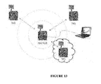
- FIG. 13 is a schematic of the DecaWave TREK1000 UWB position tracking system.
- FIG. 14 illustrates another embodiment of the invention for running and cycling guidance.
- FIG. 1 shows a system overview using Real Time Kinematic (RTK) satellite navigation employing the Global Positioning System (GPS) for positioning.
- RTK Real Time Kinematic
- GPS Global Positioning System
- the leader's and follower's absolute positions are computed on the order of centimeters using three Real-Time Kinematics (RTK) Global Positioning System (GPS) units, one of which is a fixed base station.
- RTK Real-Time Kinematics
- GPS Global Positioning System
- the follower can thus compute deviations from the leader's track at any point, not just the leader's instantaneous position.
- Microcontrollers at each position communicate with the GPS units, perform calculations and command outputs.
- the three units communicate with one another using radio hardware capable of spanning distances of up to 20 km.
- Detail 101 in FIG. 1 shows the follower unit that performs the following actions:
- Detail 102 in FIG. 1 shows the lead unit that:
- Detail 103 in FIG. 1 shows the base station that sends GPS data to the follower and leader so that absolute positions can be obtained.
- FIG. 2 provides a flowchart for the system in three different operational modes described below.
- Mode 1 “On the fly” path creation, guidance, following and feedback.
- the mobile leader unit and the mobile follower unit communicate via radio.
- the leader's accurate (order of centimeters) position and track is communicated to the follower.
- the follower's position and deviation from the leader's track is then computed via an algorithm on the follower's microcontroller unit.
- Feedback of multiple forms including but not limited to tactile, audio and visual cues alert the follower to their deviation from the leader's track.
- Parameters of the algorithm can be adjusted to the follower's preferences, such as feedback preferences that include how the follower is alerted to correct course, location on the track of the leader in front of the follower where position deviance is calculated, and tolerances, for example, the leader may receive feedback if the position of the follower deviates beyond a desired distance from the leader's track.
- Mode 2 Fluorescent adjustment of an established track with feedback.
- the follower can choose an existing track if one has been established (see Mode 3—Creating a track for saving—below).
- the feedback and options are the same as in Mode 1, but there is no leader present.
- Mode 3 creating a track for saving.
- the lead unit can be used on its own to create and save tracks for the follower to use without the lead unit present.
- the tracks created by the leader are named and given a description for the follower unit to pick from at a later time.
- FIG. 3 shows a description of the system computing path deviations.
- the follower unit calculates its deviation from the lead unit's path using the algorithm depicted in FIG. 3 .
- the leader's “X” in FIG. 3 is the leader setting the path.
- the other “X” represents the follower.
- the follower's coding method will be:
- FIG. 4 is a flowchart of the path deviation algorithm.
- the follower can also choose to look slightly ahead of their own path to get information on upcoming events in order to plan trajectory changes. This information is relayed to the follower via additional actuators and instruments—vibration motors in additional locations and audible alerts.
- FIG. 5 illustrates the algorithm for trajectory planning.
- the leader's first derivative of velocity as a function of time is calculated so that an intensity or acceleration of the direction change can be sent to the follower.
- Information is transmitted from the leader to the follower on upcoming trajectory changes so that the follower can prepare to change direction.
- the follower is alerted using separate feedback actuators different from the path error feedback actuators and alerts to upcoming changes in direction.
- the follower can customize the system to specify how far ahead of their own path they want to look.
- the information carries the intensity of the direction change as well.
- the algorithm computes the derivative of the position and velocity to determine how intense the change of trajectory is. This allows the follower to know how to prepare for the upcoming path.
- the follower wears a suit with integrated vibration motors in key locations to interpret path corrections needed to follow the leader path.
- the vibration motors would be integrated into a wearable garment to be easily donned and doffed by the user.
- FIG. 6 shows a photograph of one such commercially available vibration actuator that could be used in said suit.
- the leader's unit receives the follower's position and in one embodiment calculates if the follower has deviated from the leader's track beyond a specified parameter. If so, the leader is alerted via tactile, audible, or visual feedback.
- FIG. 7 shows on an anthropomorphic representation possible locations for tactile feedback actuators. Detail 701 in FIG. 7 shows an actuator on the upper arm where a vibration alerts a skier if they deviate from the guide's path. Detail 702 in FIG. 7 shows an actuator on the lower arm where a vibration indicates to a skier upcoming turns based on the guide's position.
- FIG. 8 illustrates the leader feedback mechanism and detail 803 in FIG. 8 shows a location for a vibration alert to the guide if the skier deviates from a path too much or is too far behind.
- FIG. 10 shows components for one embodiment of the system for a visually impaired competition skiing guidance system.
- visually impaired skiing competition a sighted guide skier skis ahead of a Visually Impaired (VI) skier.
- the VI skier attempts to follow their guide down a gated ski course at a high rate of speed.
- the skiing team of sighted and VI skier with the shortest time on the course wins the competition. If a gate is missed, the team is disqualified.
- the sighted guide and the VI skier communicate either by voice, audible signals such as ski pole taps, or communication devices such as Bluetooth headsets.
- This new guidance system could be used to enhance communication between the guide and the VI skier and improve race course performance.
- FIG. 10 shows how the lead (sighted) skier sets a virtual path and the follower VI skier's device can detect that path and alert him or her to deviations from that path using tactile or audio feedback.
- the follower also can configure the system to provide information about upcoming events such as turns or elevation changes via additional encoded feedback.
- the leader is alerted when the VI skier deviates too far from the desired path trajectory. This allows the leader to focus on skiing the fastest trajectory in the race course by alleviating the need to be constantly looking back to check on the follower's position.
- FIG. 11 shows components of the system in another embodiment for a visually impaired recreational skiing guidance system.
- the guidance system could also be used for recreational skiing at commercial ski resorts to enable a much greater level of independence and enjoyment for visually impaired skiers.
- VI skiers usually ski with a sighted guide in front, behind, or beside them. The pair communicates using voice, audible signals, or radio communications.
- the sighted guide gives the VI skier information on where to go, obstacles to avoid, and other skiers in the area. Tracks can be established using this embodiment of the invention and recorded by sighted skiers in advance, in areas designated for VI skiing. The VI skier can then go to that location and use the guidance device to follow that track with feedback and minimal or no intervention by a sighted guide.
- Detail 1101 in FIG. 11 show the location of actuators to provide feedback to the user of current path deviations and upcoming turns based on the set path.
- the device is implemented in the following manner.
- the guidance system can be used as a navigation system through a museum or other indoor exhibits as illustrated in FIG. 12 .
- the feedback system which can include but is not limited to haptic, audible alerts, or visual cues, can be used indoors using a different implementation of position location.
- Method one uses an active Radio Frequency Identification (RFID) trilateration system.
- Method 2 uses an Ultra Wide Band (UWB system) such as the commercially available DecaWave Two-Way-Ranging (TWR) Real Time Location Systems (RTLS) shown in FIG. 13 .
- Other methods include Infrared Positioning and Ultrasonic Positioning.
- FIG. 14 illustrates another embodiment of the invention for running and cycling guidance.
- the system can be used to guide a person with a visual impairment while running or cycling, whether in a competitive event or recreationally.
- Detail 1401 in FIG. 14 is the high accuracy (order of centimeters) track that is established. The track is set and read at a high frequency (e.g., 10-50 Hz).
- Detail 1402 in FIG. 14 are obstacles and bystanders that can be avoided due to the set track.
Landscapes
- Engineering & Computer Science (AREA)
- Radar, Positioning & Navigation (AREA)
- Remote Sensing (AREA)
- Physics & Mathematics (AREA)
- General Physics & Mathematics (AREA)
- Computer Networks & Wireless Communication (AREA)
- Automation & Control Theory (AREA)
- Navigation (AREA)
- Position Fixing By Use Of Radio Waves (AREA)
Abstract
An innovative path guidance system and method has been invented that in a preferred embodiment allows visually impaired people to follow a dynamically changing path that avoids obstacles and arrive at destination with minimal intervention by a sighted guide. The disclosed invention has the leader set a track electronically, and employs but is not limited to haptic feedback and audible alerts used in combination or individually, to help the visually impaired person control his or her trajectory. The visually impaired follower can be following a leader setting the path in real time or following a path established by a guide at an earlier time and recorded.
Description
A portion of the disclosure of this patent document contains material, which is subject to copyright protection. The owner has no objection to the facsimile reproduction by anyone of the patent document or the patent disclosure, as it appears in the Patent and Trademark Office patent files or records, but otherwise reserves all copyrights whatsoever.
Certain marks referenced herein may be common law or registered trademarks of third parties affiliated or unaffiliated with the applicant or the assignee. Use of these marks is by way of example and shall not be construed as descriptive or to limit the scope of this invention to material associated only with such marks.
The present invention relates to an innovative path guidance system and associated method to guide visually impaired people along a path that avoids obstacles and arrive at a destination with minimal or no intervention by a sighted guide.
Prior guidance methods for leader/follower systems using simple voice communication over radio or Bluetooth systems limit the quantity and level of detail that can be employed by the users. The time needed by a leader who functions as a guide for a follower individual or group of people, to describe geographic features, obstacles, hazards, and desired actions to a follower or followers is long and compromises the ability of followers to react and effect collision avoidance maneuvers or simply follow specified paths that are dynamically changing. Without visual confirmation, the leader also cannot discern if followers are aligned with specified paths. These issues are particularly acute for Visually Impaired (VI) participants in recreational and competitive athletic events.
A new path guidance system has been invented that incorporates a virtual path created by the leader and detected by the follower(s). An algorithm:
-
- 1. Computes the followers deviation from the path;
- 2. Alerts the follower via multiple forms of feedback to direct the follower back to the desired path;
- 3. Alerts the leader of the follower(s) deviation from the path; and,
- 4. Gives the follower predictive information of upcoming path changes and their intensity.
Prior art has used GPS, Inertial Measurement Units (IMUs), ultrasound and other tracking methods in leader/follower systems.
Hogg, et. al. (2001) uses GPS and Inertial Measurements to create a path following system for pack robots to follow a leader. The path of the leader is recorded and then downloaded to the following robots. The path following algorithm uses a “carrot following” approach to command the following robot to a path sub goal.
The present invention differs in that it transmits the leader's data to the follower in “real time” or near real-time. Additionally, the present invention uses two way communications to alert the leader to the follower's deviation from a path. The follower also gets information on upcoming path changes of the leader and the intensity of those upcoming changes to prepare for future movements.
Cosgun (2014) presents a navigation system that guides a human with a visual impairment to an object using haptic feedback in the form of a vibrating belt. The present invention differs in that it provides real time guidance to follow a path that can be dynamically changing, not guidance to a stationary object as in Cosgun (2014). Also, in the present invention, it can be important for a follower path to be in alignment with different portions of a leader path history.
Henze (2006) investigates different forms of haptic feedback to aid in guidance of pedestrians with a visual impairment. That system however is not intended for precise path following as is the current invention.
An innovative path guidance system and associated methods have been invented that differs significantly from prior art path guidance systems that use a leader/follower system. Prior art leader/follower path guidance systems ensuring accurate path alignment between a leader and follower path, especially where follower paths are dynamically changing, have historically focused on one way communication between the leader steering a follower using voice commands or visual cues along path coordinates, or the follower tracking closely behind the leader.
The new path guidance system and associated methods of use (henceforth referred to as “the invention”) incorporates a position guidance device or devices, leader and follower feedback devices, algorithms embedded in a microcontroller or controllers that compute deviations of the follower from a prescribed track and alerts the follower of deviations from the track via different sensory modalities including but not limited to haptics feedback, auditory cues, and/or visual cues used individually or in combination.
One embodiment of the invention includes a lead unit that sets a three dimensional virtual track in space and communicates with a second unit so that the second unit can detect that track. An algorithm computes the deviations of the follower from that track and alerts the follower via different feedback mechanisms. The follower unit also communicates with the lead unit to enable the leader to be alerted to the follower's deviation from the track.
Feedback mechanisms include but are not limited to haptic feedback, audio alerts, or visual cues used individually or in combination to enable users to employ the data and feedback to alter trajectory and plan future course changes. Alternate modes of operation include a lead unit designating and saving a track for later use by a follower. The follower can then proceed to a location and choose from a set of tracks to follow.
The system developed is a high speed, highly accurate position (order of centimeters) guidance and feedback device enabled with user controlled parameters. The system unit can be highly portable, wearable and rugged. It can be battery powered, and a rechargeable system that complies, for example, with the rules and regulations for various competitive sporting events set by the respective governing bodies.
A preferred embodiment of this invention is for use by Visually Impaired (VI) participants in recreational and competitive sporting events. Typically, path guidance to VI participants in recreational and sporting events is provided by a sighted guide or leader that provides path guidance using voice audible signals or communication devices such as Bluetooth headsets to a VI follower. These leader/follower systems focus on one way communication between the leader and follower for the path coordinates, or the follower tracking closely behind the leader. The need for the leader to observe the follower and communicate path changes has considerable latency in effecting path changes by the follower and imposes a significant cognitive load constraining task performance by the follower and imposing increased collision and path misalignment risks, especially for VI athletic participants.
The preferred embodiment does not require or only minimally requires a sighted guide's intervention for path guidance of a VI participant and remedies the shortcomings for VI participants. These remedies are at least threefold.
1. Reduced cognitive load—In this embodiment, the follower receives information from the leader and interprets it using various algorithms to compute current deviation from the desired path, as well as information regarding direction and intensity of upcoming events such as follower course changes, hazards and collision avoidance. The intuitive user interface gives the user an easy way to process this information and lets the follower user control his or her actions more independently with a reduced cognitive load that might be associated with other communication methods such as voice. This results in an overall reduction of the cognitive load on the user by lessening the amount of cognitive processing required by the user. It is also safer in that the user gets more information on direction changes and can react more quickly to hazards and collision avoidance.
2. Reduced latency in effecting path changes—Latency for voice guidance by a leader/follower is long compared to latency achieved in the current embodiment for VI followers that employs a system of tactile or audible alerts where vocal instruction does not have to be transmitted, interpreted, and organized to achieve a follower responding reaction. Also, the path created by the leader with this system can be saved so that the follower does not need to be directly behind the leader. The coordinates of the path can also be saved so that the follower can detect the path even when the leader is not present.
3. Two-way information transfer—While the follower gets path data from the leader, the leader can also receive information from the follower's unit as to how successfully the follower is on the desired path. This lets the leader make necessary adjustments and reduces the need for the leader to be constantly visually checking the status of the follower.
The follower can thus compute deviations from the leader's track at any point, not just the leader's instantaneous position. Microcontrollers at each position communicate with the GPS units, perform calculations and command outputs. The three units communicate with one another using radio hardware capable of spanning distances of up to 20 km. Detail 101 in FIG. 1 shows the follower unit that performs the following actions:
-
- RECEIVES GPS data from BASE STATION and computes RTK position
- RECEIVES GPS data from LEAD and computes difference in position at current location
- RECEIVES GPS data from LEAD to see what moves LEAD is currently making
- ACTUATES tactile feedback
- SENDS position to LEAD
-
- RECEIVES data from BASE STATION and computes RTK position
- SENDS position information to FOLLOWER
- RECEIVES position from FOLLOWER, computes FOLLOWER'S deviation from path and FOLLOWER'S distance from LEAD
- ACTUATES tactile feedback
Feedback of multiple forms including but not limited to tactile, audio and visual cues alert the follower to their deviation from the leader's track. Parameters of the algorithm can be adjusted to the follower's preferences, such as feedback preferences that include how the follower is alerted to correct course, location on the track of the leader in front of the follower where position deviance is calculated, and tolerances, for example, the leader may receive feedback if the position of the follower deviates beyond a desired distance from the leader's track.
The follower reaches a position at its local time, t=tFOL n, and wants to check “when the leader was at this latitude, what was the longitude of the leader?” Thus the equation becomes:
(LEAD LONG)[when leadlat=follat]−(FOL LONG)[current]=ERROR.
(LEAD LONG)[when leadlat=follat]−(FOL LONG)[current]=ERROR.
The follower's coding method will be:
- 1. Get current coordinates (Lat, Long).
- 2. Get leader's coordinate history (Lat, Long).
- 3. Look through leader's past and find when leader's longitude was equal to current longitude. Use an approximation factor to prevent errors of never finding an exact match.
- 4. Perform error calculation as formula above.
- 5. Output desired action to feedback mechanism.
- 6. Monitor buffer size for how much leader data is kept and how it is managed.
- 7. Monitor LAT times and eliminate earlier LATs to prevent problem of multiple LATs that occur when path loops back on previous location
An alternative method for finding position differences are:
- 1. Calculate distance between leader and follower.
- 2. Based on velocity (calculated or from data) know how far back to look in leader's history using time and look around for matching latitudes.
Information on path deviances are relayed to the users using various feedback systems. These systems include individually or in combination, but not limited to haptics, audible alerts, and visual cues. In one embodiment, the follower wears a suit with integrated vibration motors in key locations to interpret path corrections needed to follow the leader path. The vibration motors would be integrated into a wearable garment to be easily donned and doffed by the user. FIG. 6 shows a photograph of one such commercially available vibration actuator that could be used in said suit.
The leader's unit receives the follower's position and in one embodiment calculates if the follower has deviated from the leader's track beyond a specified parameter. If so, the leader is alerted via tactile, audible, or visual feedback. FIG. 7 shows on an anthropomorphic representation possible locations for tactile feedback actuators. Detail 701 in FIG. 7 shows an actuator on the upper arm where a vibration alerts a skier if they deviate from the guide's path. Detail 702 in FIG. 7 shows an actuator on the lower arm where a vibration indicates to a skier upcoming turns based on the guide's position. FIG. 8 illustrates the leader feedback mechanism and detail 803 in FIG. 8 shows a location for a vibration alert to the guide if the skier deviates from a path too much or is too far behind.
Currently, the sighted guide and the VI skier communicate either by voice, audible signals such as ski pole taps, or communication devices such as Bluetooth headsets. This new guidance system could be used to enhance communication between the guide and the VI skier and improve race course performance.
Visually impaired (VI) skiers usually ski with a sighted guide in front, behind, or beside them. The pair communicates using voice, audible signals, or radio communications. The sighted guide gives the VI skier information on where to go, obstacles to avoid, and other skiers in the area. Tracks can be established using this embodiment of the invention and recorded by sighted skiers in advance, in areas designated for VI skiing. The VI skier can then go to that location and use the guidance device to follow that track with feedback and minimal or no intervention by a sighted guide. Detail 1101 in FIG. 11 show the location of actuators to provide feedback to the user of current path deviations and upcoming turns based on the set path.
The device is implemented in the following manner.
- 1. Base station is installed at the mountain for precise RTK GPS positioning. Only one mobile unit is required.
- 2. A sighted skier, wearing one unit, establishes fixed tracks on the mountain and paths are recorded.
- 3. VI skiers wear unit and choose the desired track via an audio interface.
- 4. A tactile or audible feedback system, similar to the above mentioned race system, helps guide the VI skier.
- 5. VI skiers can now lead the way with less input from the guide following behind. Only the VI skier needs to wear the unit.
In another embodiment of the invention, the guidance system can be used as a navigation system through a museum or other indoor exhibits as illustrated in FIG. 12 .
The feedback system, which can include but is not limited to haptic, audible alerts, or visual cues, can be used indoors using a different implementation of position location. Method one uses an active Radio Frequency Identification (RFID) trilateration system. Method 2 uses an Ultra Wide Band (UWB system) such as the commercially available DecaWave Two-Way-Ranging (TWR) Real Time Location Systems (RTLS) shown in FIG. 13 . Other methods include Infrared Positioning and Ultrasonic Positioning.
As in the recreational skiing system implementation illustrated in FIG. 11 and discussed above, different paths are pre-established. The visual impaired guest then picks one of these paths to visit the exhibits and sites he or she desires. The user's location is found using active RFID and tactile and audible feedback guides him or her along the path.
Claims (9)
1. A path guidance apparatus comprising:
position location transmitting and receiving devices wherein said position location transmitting and receiving devices have transmission and receiving rates within a range of 0.5 Hz to 15 KHz and wherein said position location transmitting and receiving devices determine location with an accuracy under 100 cm;
a medium for recording, storing and recalling coordinates of a prescribed path;
microcontrollers with at least one Central Processing Unit (CPU) wherein said CPU has a processing speed exceeding 16 MHz and wherein said CPU has embedded algorithms that calculate deviations of a follower from a path prescribed by a guide person in less than 1 second; and,
a feedback system that alerts a follower of deviations from prescribed paths in less than 1 second.
2. The path guidance apparatus in claim 1 further comprising:
a base station employing a Real Time Kinematic (RTK) Global Positioning Systems (GPS) for position location; and,
a remote follower Real Time Kinematic (RTK) Global Positioning System (GPS) for follower position location wherein said remote follower Real Time Kinematic (RTK) Global Positioning Systems (GPS) have sampling rates within a range of 5 to 50 Hz.
3. The path guidance apparatus in claim 2 further comprising Inertial Measurement Units (IMU) to augment GPS data for position location.
4. The path guidance apparatus in claim 1 further comprising a base station employing Real Time Kinematic (RTK) Global Positioning System (GPS) for position location, a remote leader GPS unit for leader position location and a remote follower GPS for follower position location where said GPS systems have sampling rates within a range of 5 to 50 Hz.
5. The path guidance apparatus in claim 4 further comprising Inertial Measurement Units (IMU) to augment GPS data for position location.
6. The path guidance apparatus in claim 1 further comprising an active Radio Frequency Identification (RFID) system for position location of a leader and follower.
7. The path guidance apparatus in claim 1 further comprising an Ultra Wide Band Two-Way-Ranging Real Time Location System for position location of a leader and follower.
8. The path guidance apparatus in claim 1 further comprising a haptic feedback system to alert the follower of path deviations in less than 1 second.
9. The path guidance apparatus in claim 1 further comprising an auditory alert system to inform the follower of path deviations in less than 1 second.
Priority Applications (2)
| Application Number | Priority Date | Filing Date | Title |
|---|---|---|---|
| US14/820,463 US9726501B2 (en) | 2015-08-06 | 2015-08-06 | Path guidance system for the visually impaired |
| US15/635,816 US9841283B2 (en) | 2015-08-06 | 2017-06-28 | Path guidance system for the visually impaired |
Applications Claiming Priority (1)
| Application Number | Priority Date | Filing Date | Title |
|---|---|---|---|
| US14/820,463 US9726501B2 (en) | 2015-08-06 | 2015-08-06 | Path guidance system for the visually impaired |
Related Child Applications (1)
| Application Number | Title | Priority Date | Filing Date |
|---|---|---|---|
| US15/635,816 Division US9841283B2 (en) | 2015-08-06 | 2017-06-28 | Path guidance system for the visually impaired |
Publications (2)
| Publication Number | Publication Date |
|---|---|
| US20170038214A1 US20170038214A1 (en) | 2017-02-09 |
| US9726501B2 true US9726501B2 (en) | 2017-08-08 |
Family
ID=58052486
Family Applications (2)
| Application Number | Title | Priority Date | Filing Date |
|---|---|---|---|
| US14/820,463 Active 2035-09-04 US9726501B2 (en) | 2015-08-06 | 2015-08-06 | Path guidance system for the visually impaired |
| US15/635,816 Expired - Fee Related US9841283B2 (en) | 2015-08-06 | 2017-06-28 | Path guidance system for the visually impaired |
Family Applications After (1)
| Application Number | Title | Priority Date | Filing Date |
|---|---|---|---|
| US15/635,816 Expired - Fee Related US9841283B2 (en) | 2015-08-06 | 2017-06-28 | Path guidance system for the visually impaired |
Country Status (1)
| Country | Link |
|---|---|
| US (2) | US9726501B2 (en) |
Cited By (3)
| Publication number | Priority date | Publication date | Assignee | Title |
|---|---|---|---|---|
| CN110927767A (en) * | 2019-11-28 | 2020-03-27 | 合肥工业大学 | Following system for special crowds |
| US10677926B2 (en) * | 2018-01-15 | 2020-06-09 | Guy E Mossman | Sensory augmentation system |
| US10996069B2 (en) | 2018-09-06 | 2021-05-04 | International Business Machines Corporation | Adaptive, imitative navigational assistance |
Families Citing this family (5)
| Publication number | Priority date | Publication date | Assignee | Title |
|---|---|---|---|---|
| WO2018035559A1 (en) | 2016-08-22 | 2018-03-01 | Surf Sense Devices Pty Ltd | Frameworks and methodologies configured to enable real-time location-specific determination of recreationally relevant wave characteristic data, including generation and delivery of location-specific ocean wave notifications |
| US11408749B2 (en) * | 2017-05-30 | 2022-08-09 | Stephen Wesley Schad, JR. | Personal navigation system haptic device |
| CN109285395B (en) * | 2018-12-05 | 2021-01-29 | 安徽鑫巨源电子科技有限公司 | Intelligent distance control following interactive explanation projection method and system |
| CN110703810B (en) * | 2019-11-18 | 2022-07-15 | 浙江天尚元科技有限公司 | Following vehicle with track prediction and random position tracking functions and following method |
| CN110879069A (en) * | 2019-12-11 | 2020-03-13 | 济南大学 | UWB SLAM-oriented Kalman/R-T-S hybrid positioning method and system |
Citations (33)
| Publication number | Priority date | Publication date | Assignee | Title |
|---|---|---|---|---|
| US4853839A (en) * | 1985-10-01 | 1989-08-01 | Scientific-Atlanta, Inc. | Antenna position tracking apparatus and methods |
| US6580978B1 (en) | 2002-04-15 | 2003-06-17 | United Defense, Lp | Path following using bounded beacon-aided inertial navigation |
| US20040158358A1 (en) | 2003-02-06 | 2004-08-12 | Matsushita Electric Industrial Co., Ltd. | Method of teaching traveling path to robot and robot having function of learning traveling path |
| US7022131B1 (en) * | 1998-05-29 | 2006-04-04 | By-Pass Inc. | Methods and devices for vascular surgery |
| US7039522B2 (en) | 2003-11-12 | 2006-05-02 | Steven Landau | System for guiding visually impaired pedestrian using auditory cues |
| WO2006045819A2 (en) | 2004-10-26 | 2006-05-04 | The European Community, Represented By The European Commission | Navigation system for disabled persons, in particular visually impaired persons |
| US20060116798A1 (en) | 2004-11-30 | 2006-06-01 | Mark Gibson | Method and system for implementing automatic vehicle control with parameter-driven disengagement |
| US20070293149A1 (en) * | 2006-06-16 | 2007-12-20 | Roy Wubker | Portable handheld satellite phone conversion module |
| US20080059059A1 (en) * | 2006-05-18 | 2008-03-06 | Cohen Clark E | Generalized high performance navigation system |
| US20100256902A1 (en) * | 2004-12-17 | 2010-10-07 | Information Patterns Llc | Methods and Apparatus for Geo-Collaboration |
| US20110172850A1 (en) * | 2009-09-14 | 2011-07-14 | Israel Aerospace Industries Ltd. | Infantry robotic porter system and methods useful in conjunction therewith |
| US20110169633A1 (en) * | 2006-10-05 | 2011-07-14 | Gary Mark Lauder | Systems and methods of automated correlation of weapon fire data with monitored persons-of-interest/location data |
| US20120086606A1 (en) * | 2010-10-08 | 2012-04-12 | Mathews Michael B | Doppler aided inertial navigation |
| US8185101B1 (en) * | 2008-04-10 | 2012-05-22 | Sandia Corporation | Handheld portable real-time tracking and communications device |
| US20120171644A1 (en) * | 2009-09-23 | 2012-07-05 | Marathon Robotics Pty Ltd | Methods and systems for use in training armed personnel |
| US20120209504A1 (en) * | 2006-08-24 | 2012-08-16 | Blackbird Technologies, Inc. | Mobile unit and system having integrated mapping, communications and tracking |
| US8255144B2 (en) | 1997-10-22 | 2012-08-28 | Intelligent Technologies International, Inc. | Intra-vehicle information conveyance system and method |
| US20130016879A1 (en) * | 2009-12-28 | 2013-01-17 | Softkinetic | Tracking method |
| US20130030606A1 (en) | 2011-07-25 | 2013-01-31 | GM Global Technology Operations LLC | Autonomous convoying technique for vehicles |
| US20130082828A1 (en) * | 2007-03-13 | 2013-04-04 | Blackbird Technologies, Inc. | Mobile asset tracking unit, system and method |
| US20130166198A1 (en) * | 2006-05-31 | 2013-06-27 | Benjamin E. Funk | Method and system for locating and monitoring first responders |
| US20130191017A1 (en) | 2009-11-16 | 2013-07-25 | Trimble Navigation Limited | Method and system for augmenting a guidance system with a path sensor |
| US20140032069A1 (en) | 2010-03-17 | 2014-01-30 | Honda Motor Co., Ltd. | System For And Method Of Maintaining A Driver Intended Path |
| US20140100771A1 (en) * | 2012-10-04 | 2014-04-10 | Frank Edughom Ekpar | Method and apparatus for synchronized navigation by mobile agents |
| US20140342753A1 (en) * | 2013-05-14 | 2014-11-20 | Sony Corporation | Automatic friend following application |
| US20150192420A1 (en) * | 2014-01-09 | 2015-07-09 | Telecommunication Systems, Inc. | Follow-me application |
| US20160059881A1 (en) * | 2014-08-26 | 2016-03-03 | Autonomous Solutions, Inc. | Method and system for controlling a vehicle to a moving point |
| US20160223340A1 (en) * | 2015-02-03 | 2016-08-04 | The Regents Of The University Of Michigan | Last-Mile Navigation Using Smartphones |
| US20160267755A1 (en) * | 2015-03-13 | 2016-09-15 | Toyota Jidosha Kabushiki Kaisha | Object Detection and Localized Extremity Guidance |
| US9478147B2 (en) * | 2012-05-17 | 2016-10-25 | The University Of Connecticut | Methods and apparatus for interpersonal coordination analysis and training |
| US20160335917A1 (en) * | 2015-05-13 | 2016-11-17 | Abl Ip Holding Llc | System and method to assist users having reduced visual capability utilizing lighting device provided information |
| US9517175B1 (en) * | 2013-03-14 | 2016-12-13 | Toyota Jidosha Kabushiki Kaisha | Tactile belt system for providing navigation guidance |
| US20170006428A1 (en) * | 2015-06-30 | 2017-01-05 | International Business Machines Corporation | Leader and follower management system for wearable devices |
-
2015
- 2015-08-06 US US14/820,463 patent/US9726501B2/en active Active
-
2017
- 2017-06-28 US US15/635,816 patent/US9841283B2/en not_active Expired - Fee Related
Patent Citations (34)
| Publication number | Priority date | Publication date | Assignee | Title |
|---|---|---|---|---|
| US4853839A (en) * | 1985-10-01 | 1989-08-01 | Scientific-Atlanta, Inc. | Antenna position tracking apparatus and methods |
| US8255144B2 (en) | 1997-10-22 | 2012-08-28 | Intelligent Technologies International, Inc. | Intra-vehicle information conveyance system and method |
| US7022131B1 (en) * | 1998-05-29 | 2006-04-04 | By-Pass Inc. | Methods and devices for vascular surgery |
| US6580978B1 (en) | 2002-04-15 | 2003-06-17 | United Defense, Lp | Path following using bounded beacon-aided inertial navigation |
| US20040158358A1 (en) | 2003-02-06 | 2004-08-12 | Matsushita Electric Industrial Co., Ltd. | Method of teaching traveling path to robot and robot having function of learning traveling path |
| US7039522B2 (en) | 2003-11-12 | 2006-05-02 | Steven Landau | System for guiding visually impaired pedestrian using auditory cues |
| WO2006045819A2 (en) | 2004-10-26 | 2006-05-04 | The European Community, Represented By The European Commission | Navigation system for disabled persons, in particular visually impaired persons |
| US20060116798A1 (en) | 2004-11-30 | 2006-06-01 | Mark Gibson | Method and system for implementing automatic vehicle control with parameter-driven disengagement |
| US20100256902A1 (en) * | 2004-12-17 | 2010-10-07 | Information Patterns Llc | Methods and Apparatus for Geo-Collaboration |
| US20080059059A1 (en) * | 2006-05-18 | 2008-03-06 | Cohen Clark E | Generalized high performance navigation system |
| US20130166198A1 (en) * | 2006-05-31 | 2013-06-27 | Benjamin E. Funk | Method and system for locating and monitoring first responders |
| US20070293149A1 (en) * | 2006-06-16 | 2007-12-20 | Roy Wubker | Portable handheld satellite phone conversion module |
| US20120209504A1 (en) * | 2006-08-24 | 2012-08-16 | Blackbird Technologies, Inc. | Mobile unit and system having integrated mapping, communications and tracking |
| US20110169633A1 (en) * | 2006-10-05 | 2011-07-14 | Gary Mark Lauder | Systems and methods of automated correlation of weapon fire data with monitored persons-of-interest/location data |
| US20130082828A1 (en) * | 2007-03-13 | 2013-04-04 | Blackbird Technologies, Inc. | Mobile asset tracking unit, system and method |
| US8185101B1 (en) * | 2008-04-10 | 2012-05-22 | Sandia Corporation | Handheld portable real-time tracking and communications device |
| US20110172850A1 (en) * | 2009-09-14 | 2011-07-14 | Israel Aerospace Industries Ltd. | Infantry robotic porter system and methods useful in conjunction therewith |
| US20120171644A1 (en) * | 2009-09-23 | 2012-07-05 | Marathon Robotics Pty Ltd | Methods and systems for use in training armed personnel |
| US20130191017A1 (en) | 2009-11-16 | 2013-07-25 | Trimble Navigation Limited | Method and system for augmenting a guidance system with a path sensor |
| US8655536B2 (en) | 2009-11-16 | 2014-02-18 | Trimble Navigation Limited | Method and system for augmenting a guidance system with a path sensor |
| US20130016879A1 (en) * | 2009-12-28 | 2013-01-17 | Softkinetic | Tracking method |
| US20140032069A1 (en) | 2010-03-17 | 2014-01-30 | Honda Motor Co., Ltd. | System For And Method Of Maintaining A Driver Intended Path |
| US20120086606A1 (en) * | 2010-10-08 | 2012-04-12 | Mathews Michael B | Doppler aided inertial navigation |
| US20130030606A1 (en) | 2011-07-25 | 2013-01-31 | GM Global Technology Operations LLC | Autonomous convoying technique for vehicles |
| US9478147B2 (en) * | 2012-05-17 | 2016-10-25 | The University Of Connecticut | Methods and apparatus for interpersonal coordination analysis and training |
| US20140100771A1 (en) * | 2012-10-04 | 2014-04-10 | Frank Edughom Ekpar | Method and apparatus for synchronized navigation by mobile agents |
| US9517175B1 (en) * | 2013-03-14 | 2016-12-13 | Toyota Jidosha Kabushiki Kaisha | Tactile belt system for providing navigation guidance |
| US20140342753A1 (en) * | 2013-05-14 | 2014-11-20 | Sony Corporation | Automatic friend following application |
| US20150192420A1 (en) * | 2014-01-09 | 2015-07-09 | Telecommunication Systems, Inc. | Follow-me application |
| US20160059881A1 (en) * | 2014-08-26 | 2016-03-03 | Autonomous Solutions, Inc. | Method and system for controlling a vehicle to a moving point |
| US20160223340A1 (en) * | 2015-02-03 | 2016-08-04 | The Regents Of The University Of Michigan | Last-Mile Navigation Using Smartphones |
| US20160267755A1 (en) * | 2015-03-13 | 2016-09-15 | Toyota Jidosha Kabushiki Kaisha | Object Detection and Localized Extremity Guidance |
| US20160335917A1 (en) * | 2015-05-13 | 2016-11-17 | Abl Ip Holding Llc | System and method to assist users having reduced visual capability utilizing lighting device provided information |
| US20170006428A1 (en) * | 2015-06-30 | 2017-01-05 | International Business Machines Corporation | Leader and follower management system for wearable devices |
Non-Patent Citations (16)
| Title |
|---|
| "Sensitivity of Human Ear", date unknown, retrieved from http://hyperphysics.phy-astr.gsu.edu/hbase/sound/earsens.html. * |
| "Visible Light and the Eye's Response", date unknown, retrieved from http://www.physicsclassroom.com/class/light/Lesson-2/Visible-Light-and-the-Eye-s-Response. * |
| Akansel Cosgun, E. Akin Sisbot and Henrik I. Christensen Guidance for Human Navigation using a Vibro-Tactile Belt Interface and Robot-like Motion Planning IEEE International Conference on Robotics and Automation (ICRA 2014). |
| Burkay Sucu and Eelke Folmer The Blind Driver Challenge: Steering using Haptic Cues Computer Science & Engineering-University of Nevada. |
| Burkay Sucu and Eelke Folmer The Blind Driver Challenge: Steering using Haptic Cues Computer Science & Engineering—University of Nevada. |
| Enriquez, M., Afonin, O., Yager, B., and MacLean, K. A Pneumatic Tactile Alerting System for the Driving Environment. In Proc. of PUI '01, 1-7. |
| Hien Khne Goi, Distributed Control for Vision-based Convoying, A thesis submitted in conformity with the requirements for the degree of Masters of Applied Science Graduate Department of Electrical and Computer Engineering University of Toronto. |
| Hwang, S., and Hee Ryu, J. The Haptic Steering Wheel: Vibro-tactile Based Navigation for the Driving Environment. In Proc. of PERCOM'10, 660-665. |
| J. Giesbrecht, D. MacKay, J. Collier, S. Verret, Path Tracking for Unmanned Ground Vehicle Navigation Implementation and Adaptation of the Pure Pursuit Algorithm, Defence R&D Canada-Suffield Technical Memorandum DRDC Suffield TM 2005-224 Dec. 2005. |
| J. Giesbrecht, D. MacKay, J. Collier, S. Verret, Path Tracking for Unmanned Ground Vehicle Navigation Implementation and Adaptation of the Pure Pursuit Algorithm, Defence R&D Canada—Suffield Technical Memorandum DRDC Suffield TM 2005-224 Dec. 2005. |
| J. Giesbrecht, Development of a Vision-Based Robotic Follower Vehicle, Defence R&D Canada Technical Report DRDC Suffield TR 2009-026 Feb. 2009. |
| Kern, A., Marshall, P., Hornecker, E., Rogers, Y., Schmidt, A.: Enhancing Navigation Information with Tactile Output Embedded into the Steering Wheel Proceedings of the Seventh International Conference on Pervasive Computing, May 11-14, 2009, Nara, Japan, pp. 42-58. LNCS, Springer Verlag. |
| N. Henze, W.Heuten, and S. Boll "Non-intrusive somatosensory navigation support for blind pedestrians," in Proceedings of Eurohaptics, 2006. |
| Robert W. Hogg, Arturo L. Rankin, Michael C. McHenry, Daniel M. Helmick, Charles F. Bergh, Stergios I. Roumeliotis, Larry Matthies Sensors and Algorithms for Small Robot Leader/Follower Behavior Jet Propulsion Laboratory-California Institute of Technology. |
| Robert W. Hogg, Arturo L. Rankin, Michael C. McHenry, Daniel M. Helmick, Charles F. Bergh, Stergios I. Roumeliotis, Larry Matthies Sensors and Algorithms for Small Robot Leader/Follower Behavior Jet Propulsion Laboratory—California Institute of Technology. |
| Steven Edwin Moore Drishti: An Integrated Navigation System for the Visually Impaired and Disabled a Thesis Presented to the Graduate School of the University of Florida in Partial Fulfullment of the Requirements for the Degree of Master of Science; University of Florida 2002. |
Cited By (3)
| Publication number | Priority date | Publication date | Assignee | Title |
|---|---|---|---|---|
| US10677926B2 (en) * | 2018-01-15 | 2020-06-09 | Guy E Mossman | Sensory augmentation system |
| US10996069B2 (en) | 2018-09-06 | 2021-05-04 | International Business Machines Corporation | Adaptive, imitative navigational assistance |
| CN110927767A (en) * | 2019-11-28 | 2020-03-27 | 合肥工业大学 | Following system for special crowds |
Also Published As
| Publication number | Publication date |
|---|---|
| US20170307381A1 (en) | 2017-10-26 |
| US9841283B2 (en) | 2017-12-12 |
| US20170038214A1 (en) | 2017-02-09 |
Similar Documents
| Publication | Publication Date | Title |
|---|---|---|
| US9841283B2 (en) | Path guidance system for the visually impaired | |
| US11636939B2 (en) | Fitness activity monitoring systems and methods | |
| US9949887B2 (en) | Method, device and helmet for guiding the blind | |
| US10552967B2 (en) | Systems and methods for tracking and controlling a mobile camera to image objects of interest | |
| Loomis et al. | Navigation system for the blind: Auditory display modes and guidance | |
| Shoval et al. | The Navbelt-A computerized travel aid for the blind based on mobile robotics technology | |
| EP2972462B1 (en) | Digital tethering for tracking with autonomous aerial robot | |
| KR102102810B1 (en) | Moving guide device to guide user's movement using the drone and method for controlling the same | |
| JP2019536002A (en) | Method, system and software for navigation in a global positioning system (GPS) rejection environment | |
| Garaj et al. | A system for remote sighted guidance of visually impaired pedestrians | |
| US11725958B2 (en) | Route guidance and proximity awareness system | |
| US20230097676A1 (en) | Tactical advanced robotic engagement system | |
| JP7344589B2 (en) | target tracking system | |
| US10507157B2 (en) | Interface for constructing trajectory in an environment and environment assembly and trajectory constuction interface | |
| KR102256070B1 (en) | Golf cart system capable of changing traveling mode according to whether golf course field can enter or not and golf cart control method using the system | |
| CA3037657C (en) | Route guidance and obstacle avoidance system | |
| US20170248427A1 (en) | Systems and Methods for Guiding Swimmers | |
| Loconsole et al. | An IMU and RFID-based navigation system providing vibrotactile feedback for visually impaired people | |
| KR101287979B1 (en) | Entertainment system using moving wheelchair, host apparatus and operating method thereof | |
| US20230072692A1 (en) | Method for providing a virtual reality experience for at least one passenger of an amusement ride, and amusement ride | |
| EP4336206A1 (en) | Localization device | |
| Gandhi et al. | Technologies for visually impaired solutions and possibilities | |
| TW202042773A (en) | Blind assistance system and method thereof | |
| Shoval et al. | BASED ON MOBILE ROBOTICS TECHNOLOGY | |
| AIDS | NAVIGATION VERSUS OBSTACLE AVOIDANCE |
Legal Events
| Date | Code | Title | Description |
|---|---|---|---|
| STCF | Information on status: patent grant |
Free format text: PATENTED CASE |
|
| FEPP | Fee payment procedure |
Free format text: MAINTENANCE FEE REMINDER MAILED (ORIGINAL EVENT CODE: REM.); ENTITY STATUS OF PATENT OWNER: SMALL ENTITY |
|
| FEPP | Fee payment procedure |
Free format text: SURCHARGE FOR LATE PAYMENT, SMALL ENTITY (ORIGINAL EVENT CODE: M2554); ENTITY STATUS OF PATENT OWNER: SMALL ENTITY |
|
| MAFP | Maintenance fee payment |
Free format text: PAYMENT OF MAINTENANCE FEE, 4TH YR, SMALL ENTITY (ORIGINAL EVENT CODE: M2551); ENTITY STATUS OF PATENT OWNER: SMALL ENTITY Year of fee payment: 4 |