US9717496B2 - Surgical stapling instrument with locking feature to lock anvil actuator - Google Patents
Surgical stapling instrument with locking feature to lock anvil actuator Download PDFInfo
- Publication number
- US9717496B2 US9717496B2 US14/944,387 US201514944387A US9717496B2 US 9717496 B2 US9717496 B2 US 9717496B2 US 201514944387 A US201514944387 A US 201514944387A US 9717496 B2 US9717496 B2 US 9717496B2
- Authority
- US
- United States
- Prior art keywords
- actuator
- adjusting knob
- instrument
- assembly
- stapling head
- Prior art date
- Legal status (The legal status is an assumption and is not a legal conclusion. Google has not performed a legal analysis and makes no representation as to the accuracy of the status listed.)
- Active
Links
Images


Classifications
-
- A—HUMAN NECESSITIES
- A61—MEDICAL OR VETERINARY SCIENCE; HYGIENE
- A61B—DIAGNOSIS; SURGERY; IDENTIFICATION
- A61B17/00—Surgical instruments, devices or methods, e.g. tourniquets
- A61B17/11—Surgical instruments, devices or methods, e.g. tourniquets for performing anastomosis; Buttons for anastomosis
- A61B17/115—Staplers for performing anastomosis in a single operation
- A61B17/1155—Circular staplers comprising a plurality of staples
-
- A—HUMAN NECESSITIES
- A61—MEDICAL OR VETERINARY SCIENCE; HYGIENE
- A61B—DIAGNOSIS; SURGERY; IDENTIFICATION
- A61B17/00—Surgical instruments, devices or methods, e.g. tourniquets
- A61B17/068—Surgical staplers, e.g. containing multiple staples or clamps
-
- A—HUMAN NECESSITIES
- A61—MEDICAL OR VETERINARY SCIENCE; HYGIENE
- A61B—DIAGNOSIS; SURGERY; IDENTIFICATION
- A61B17/00—Surgical instruments, devices or methods, e.g. tourniquets
- A61B17/11—Surgical instruments, devices or methods, e.g. tourniquets for performing anastomosis; Buttons for anastomosis
- A61B17/115—Staplers for performing anastomosis in a single operation
Definitions
- FIG. 1 depicts a perspective view of an exemplary surgical stapling instrument
- FIG. 2 depicts an enlarged longitudinal section view of a stapling head assembly of the instrument of FIG. 1 , illustrating the anvil fully open;
- FIG. 3 depicts an enlarged longitudinal section view of the stapling head assembly of FIG. 2 , illustrating the anvil in a closed position;
- FIG. 4 depicts an enlarged longitudinal section view of the stapling head assembly of FIG. 2 , illustrating the staple driver in a fired position;
- FIG. 5 depicts an enlarged longitudinal section view of an actuator handle assembly of the stapling instrument of FIG. 1 , with the staple actuating lever in a locked position;
- FIG. 6 depicts an enlarged longitudinal section view of the actuator handle assembly of FIG. 5 , with the staple actuating lever in an unlocked position;
- FIG. 7 depicts an enlarged longitudinal section view of the actuator handle assembly of FIG. 5 , in a fired position
- FIG. 8 depicts a perspective view of an exemplary safety release member in a position to lock the staple actuating lever
- FIG. 9 depicts a perspective view of the safety release member of FIG. 8 , in a position to unlock the staple actuating lever and lock the adjusting knob;
- FIG. 10 depicts a perspective view of another exemplary safety release member in a position to lock the staple actuating lever
- FIG. 11 depicts a perspective view of the safety release member of FIG. 10 , in a position to unlock the staple actuating lever and lock the adjusting knob;
- FIG. 12 depicts a longitudinal section view of an exemplary actuator handle assembly, illustrating a closure lockout member connected to a safety release member locking the staple actuating lever;
- FIG. 13 depicts a longitudinal section view of the actuator handle assembly of FIG. 12 , illustrating the safety release member locking the adjusting knob;
- FIG. 14 depicts a front view of the adjusting knob of FIG. 12 ;
- FIG. 15 depicts a perspective view of the adjusting knob of FIG. 12 ;
- FIG. 16 depicts a front view of the closure lockout member of FIG. 13 .
- FIG. 17 depicts a perspective view of the closure lockout member of FIG. 13 .
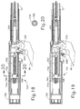
- FIG. 18 depicts a longitudinal section view of an exemplary alternative actuator handle assembly, illustrating a linkage in a hook configuration connected to a safety release member locking the staple actuating lever;
- FIG. 19 depicts a longitudinal section view of the actuator handle assembly of FIG. 18 , illustrating the linkage locking the adjusting knob;
- FIG. 20 depicts a cross section view of the adjusting knob taken along line 20 - 20 of FIG. 18 ;
- FIG. 21 depicts a longitudinal section view of another exemplary actuator handle assembly illustrating a linkage in a wedge configuration connected to a safety release member locking the staple actuating lever;
- FIG. 22 depicts a longitudinal section view of the actuator handle assembly of
- FIG. 21 illustrating the linkage locking the adjusting knob
- FIG. 23 depicts a longitudinal section view of another exemplary actuator handle assembly illustrating a linkage in a friction brake configuration connected to a safety release member locking the staple actuating lever;
- FIG. 24 depicts a longitudinal section view of the actuator handle assembly of FIG. 23 , illustrating the linkage locking the adjusting knob.
- the circular surgical anastomosis stapling instrument ( 50 ) of the present example includes a distal stapling head assembly ( 60 ) connected by a longitudinal support shaft assembly ( 70 ) to a proximal actuator handle assembly ( 80 ).
- the stapling instrument includes an anvil assembly ( 100 ) which is slidable longitudinally relative to a stapling head assembly ( 60 ).
- a rotatable adjusting knob ( 82 ) is provided at the proximal end of an actuator handle assembly ( 80 ) for adjusting the spacing between stapling head assembly ( 60 ) and anvil assembly ( 100 ).
- a movable indicator ( 84 ) is visible through a window ( 85 ) on top of handle assembly ( 80 ) to indicate the staple height selected by rotation of adjusting knob ( 82 ).
- a staple actuating lever ( 86 ) is pivotally mounted on actuator handle assembly ( 80 ) for driving the surgical staples from stapling head assembly ( 60 ) when anvil assembly ( 100 ) is closed to provide the desired staple height.
- a pivotal safety latch ( 88 ) is mounted on handle assembly ( 80 ) for locking staple actuating lever ( 86 ) against movement to preclude actuation of stapling head assembly ( 60 ) when the anvil gap is outside of a predetermined range.
- Safety latch ( 88 ) is also configured to lock adjusting knob ( 82 ) when safety latch ( 88 ) is pivoted to allow operation of staple actuating lever ( 86 ).
- stapling instrument ( 50 ) may also incorporate at least some of the teachings of U.S. Pat. No. 5,205,459 and/or any other reference(s) incorporated by reference herein.
- Other suitable components, features, and operabilities that may be incorporated into stapling instrument ( 50 ) will be apparent to those of ordinary skill in the art in view of the teachings herein.
- stapling head assembly ( 60 ) includes a tubular casing ( 61 ) that slidably receives a staple driver ( 62 ), which can be advanced and retracted by operation of actuator handle assembly ( 80 ).
- Staple driver ( 62 ) includes a plurality of fingers ( 63 ) for engaging and driving a plurality of staples ( 90 ) from a staple holder ( 68 ) mounted at the distal end of casing ( 61 ).
- Staple holder ( 68 ) includes a plurality of staple receiving slots ( 65 ) into which staples ( 90 ) are inserted.
- staple driver ( 62 ) supports a circular knife or scalpel ( 69 ) which is advanced and retracted with staple driver ( 62 ).
- Anvil assembly ( 100 ) includes a generally circular anvil ( 102 ) mounted on a hollow axially extending shaft ( 104 ), which is detachably secured to a trocar ( 73 ) slidably supported by stapling head assembly ( 60 ).
- Trocar ( 73 ) includes a pointed trocar tip ( 75 ) that is inserted into a hollow sleeve ( 105 ) at the proximal end of anvil shaft ( 104 ).
- trocar ( 73 ) and hollow sleeve ( 105 ) are reversed such that trocar ( 73 ) is mounted to anvil assembly ( 100 ), with trocar tip ( 75 ) being inserted into a hollow sleeve ( 105 ) mounted to stapling head assembly ( 60 ) for operation.
- a pair of elongated, spring-like retainer clips ( 110 ) extends longitudinally along anvil shaft ( 104 ) for engaging trocar tip ( 75 ) when trocar ( 73 ) is inserted into anvil shaft ( 104 ).
- Trocar ( 73 ) is slidably received within a central support tube ( 66 ) formed on tubular casing ( 61 ) for longitudinal movement relative to staple holder ( 68 ) mounted at the distal end of casing ( 61 ).
- Staple receiving slots ( 65 ) in staple holder ( 68 ) are arranged in a circular array for receiving surgical staples ( 90 ).
- Staple receiving slots ( 65 ) are arranged in two closely spaced concentric annular rows.
- Anvil ( 102 ) includes an annular rim ( 106 ) having a plurality of staple forming grooves for forming staples ( 90 ) when driven against anvil ( 102 ).
- retainer clips ( 110 ) permit anvil assembly ( 100 ) to be attached to or detached from trocar ( 73 ) by pushing or pulling, respectively, on anvil assembly ( 100 ).
- trocar ( 73 ) With the stapling instrument in its closed position ( FIG. 3 ), trocar ( 73 ) is retracted into central support tube ( 66 ) which restricts radial movement of retainer clips ( 110 ) to hold trocar tip ( 75 ) in place.
- anvil assembly ( 100 ) is locked to trocar ( 73 ) so that anvil ( 102 ) can resist the full firing force of the stapling instrument without disengagement of retainer clips ( 110 ) from trocar tip ( 75 ).
- actuator handle assembly ( 80 ) comprises a pair of elongated handle sections ( 81 ) that fit together to form a generally cylindrical handle.
- Stapling actuator lever ( 86 ) is pivotally mounted on handle sections ( 81 ).
- Control rod ( 300 ) is contained between handle sections ( 81 ) for longitudinal movement along actuator handle assembly ( 80 ).
- Adjusting knob ( 82 ) is rotatably supported by the proximal ends of handle sections ( 81 ) and is threadably engaged with an elongated threaded shank ( 302 ) at the proximal end of control rod ( 300 ). Threaded shank ( 302 ) and control rod ( 300 ) together form a unitary structure in this example.
- a cylindrical cap ( 89 ) is secured within the proximal end of hollow adjusting knob ( 82 ).
- Threaded shank ( 302 ) is threadably connected to an internally threaded sleeve ( 304 ) that is unitarily coupled with the distal end of adjusting knob ( 82 ).
- Threaded sleeve ( 304 ) is rotatably received in an annular wall ( 305 ) formed on each handle section ( 81 ) and rotates unitarily with adjusting knob ( 82 ).
- the distal end of control rod ( 300 ) is slidably received in an elongated groove ( 212 ) in proximal portion ( 200 ) of a compression member ( 92 ).
- Control rod ( 300 ) is connected at its distal end to a tension member ( 94 ) by a pin ( 242 ). Control rod ( 300 ) and threaded shank ( 302 ) are prevented from rotating within handle assembly ( 80 ). Thus, due to this and the threaded engagement between threaded sleeve ( 304 ) and threaded shank ( 302 ), threaded shank ( 302 ) and control rod ( 300 ) will translate relative to handle assembly ( 80 ) when adjusting knob ( 82 ) is rotated relative to handle assembly ( 80 ).
- control rod ( 300 ) By rotating adjusting knob ( 82 ) in the counterclockwise direction, as viewed in FIG. 1 , control rod ( 300 ) is advanced to move tension member ( 94 ) in the distal direction to open the gap between anvil assembly ( 100 ) and stapling head assembly ( 60 ).
- a stop ( 307 ) ( FIG. 5 ) on one of handle sections ( 81 ) engages screw ( 308 ) to limit the distal movement of control rod ( 300 ).
- control rod ( 300 ) By rotating adjusting knob ( 82 ) in the opposite direction, i.e., clockwise, control rod ( 300 ) is retracted to move tension member ( 92 ) in the proximal direction to close the gap between anvil assembly ( 100 ) and stapling head assembly ( 60 ).
- a stop ( 309 ) on cap ( 89 ) limits the proximal movement of control rod ( 300 ).
- Actuator handle assembly ( 80 ) includes a safety release bracket ( 312 ) that is slidably supported on each of handle sections ( 81 ).
- Safety release bracket ( 312 ) includes an elongated rectangular plate ( 314 ) slidably received between a pair of longitudinal ribs ( 315 ) and ( 316 ) formed on each of handle sections ( 81 ) underneath threaded shank ( 302 ) of control rod ( 300 ). Threaded shank ( 302 ) extends through an upstanding flange ( 318 ) formed at the proximal end of rectangular plate ( 314 ).
- a coil spring ( 320 ) is interposed between flange ( 318 ) and annular wall ( 305 ) on each handle section ( 81 ) to normally bias flange ( 318 ) distally against rib ( 315 ).
- a distally projecting arm ( 322 ) which slopes upwardly and terminates at a laterally projecting finger ( 324 ) for controlling the movement of indicator ( 84 ).
- FIGS. 2 and 5 Anvil assembly ( 100 ) and actuator handle assembly ( 80 ) are shown fully open in FIGS. 2 and 5 , respectively.
- safety release bracket ( 312 ) is biased distally by coil spring ( 320 ) to urge upstanding flange ( 318 ) against rib ( 315 ) with finger ( 324 ) advanced distally and disengaged from indicator lever ( 326 ).
- clip ( 306 ) on control rod ( 300 ) is moved in a proximal direction to engage flange ( 318 ) and moves safety release bracket ( 312 ) in the proximal direction.
- finger ( 324 ) on safety release bracket ( 312 ) remains disengaged from indicator lever ( 326 ).
- finger ( 324 ) engages and pivots indicator lever ( 326 ) to move indicator ( 84 ) proximally along a scale on window ( 85 ) to provide an indication of the selected staple height to be produced when the stapling instrument is fired.
- Safety latch ( 88 ) is pivotally mounted beneath safety release bracket ( 312 ) by a pivot pin extending between handle sections ( 81 ).
- Safety latch ( 88 ) includes a ledge ( 332 ) which, in its latched position ( FIG. 5 ), is disposed horizontally underneath safety release bracket ( 312 ). If the anvil gap is outside, i.e., above the predetermined range of the stapling instrument ( FIGS. 2 and 5 ), rectangular plate ( 314 ) of safety release bracket ( 312 ) overlaps ledge ( 332 ) on safety latch ( 88 ) and prevents safety latch ( 88 ) from being disengaged from staple actuating lever ( 86 ).
- Safety latch ( 88 ) thus locks staple actuating lever ( 86 ) to the open position.
- safety release bracket ( 312 ) is retracted and ledge ( 332 ) on safety latch ( 88 ) is disengaged from rectangular plate ( 314 ) of safety release bracket ( 312 ).
- Safety latch ( 88 ) can then be pivoted upward ( FIG. 6 ) to enable staple actuating lever ( 86 ) to be operated.
- Stapling instrument ( 50 ) may prevent motion of anvil assembly ( 100 ) after the anvil gap is adjusted to the desired staple height.
- actuator handle assembly ( 80 ) may be modified so that adjusting knob ( 82 ) is prevented from rotating when safety latch ( 88 ) is pivoted upward to enable staple actuating lever ( 86 ) to be operated in the predetermined range. Examples described below include variations to actuator handle assembly ( 80 ) to lock adjusting knob ( 82 ) while staple actuating lever ( 86 ) is unlocked by safety latch ( 88 ).
- Other exemplary configurations will be apparent to those of ordinary skill in the art in view of the teachings herein.
- Adjusting knob ( 82 ) may be selectively locked by a locking member that is integral to safety latch ( 88 ), such as a feature that moves unitarily with safety latch ( 88 ).
- safety latch ( 88 ) may engage a portion of actuating handle assembly ( 80 ) to prevent rotation of adjusting knob ( 82 ) when safety latch ( 88 ) is pivoted upward.
- FIGS. 8-9 show an adjusting knob locking assembly ( 450 ) that includes a knob extension rod ( 400 ), a safety latch ( 488 ), and a safety release bracket ( 412 ).
- Knob extension rod ( 400 ) is fixedly secured to adjusting knob ( 82 ) and extends distally therefrom.
- a threaded sleeve ( 404 ) having internal threading is fixedly secured to the distal end of knob extension rod ( 400 ), such that adjusting knob ( 82 ), knob extension rod ( 400 ), and threaded sleeve ( 404 ) all rotate together unitarily.
- Threaded sleeve ( 404 ) of this example is substantially similar to threaded sleeve ( 304 ) described above.
- threaded shank ( 302 ) of control rod ( 300 ) (not shown in FIGS.
- threaded sleeve ( 404 ) is received in threaded sleeve ( 404 ), such that rotation of threaded sleeve ( 404 ) causes longitudinal translation of control rod ( 300 ). While threaded sleeve ( 304 ) of examples described above is located proximal to safety release bracket ( 312 ), threaded sleeve ( 404 ) of the present example is located distal to safety release bracket ( 412 ).
- Knob extension rod ( 400 ) includes a flat sided region ( 402 ) proximal to threaded sleeve ( 404 ).
- flat sided region ( 402 ) has an octagonal cross-section.
- flat sided region ( 402 ) may include any polygon with any number of flat sides or regions and/or may be otherwise configured with a side surface that may be engaged by a feature of safety latch ( 488 ).
- Safety latch ( 488 ) is similar to safety latch ( 88 ) ( FIG.
- Safety release bracket ( 412 ) is similar to safety release bracket ( 312 ) ( FIG. 5 ), except that elongated rectangular plate ( 414 ) of safety release bracket ( 412 ) includes a slot ( 416 ) sized to allow arm ( 490 ) to pass within.
- plate ( 414 ) and arm ( 490 ) are configured such that arm ( 490 ) simply moves past an outer perimeter of plate ( 414 ) without having to pass through a slot or other feature in plate ( 414 ).
- FIG. 8 shows adjusting knob locking assembly ( 450 ) in an unlocked position relative to adjusting knob ( 82 ). While safety latch ( 488 ) is in a downward position, actuating lever ( 86 ) is locked in place while knob extension rod ( 400 ) and threaded sleeve ( 404 ) are free to rotate upon movement of adjusting knob ( 82 ). Thus, control rod ( 300 ) may be longitudinally translated based on rotation of adjusting knob ( 82 ). Once safety latch ( 488 ) is pivoted upward ( FIG. 9 ) to allow operation of staple actuating lever ( 86 ), arm ( 490 ) engages a flat sided region ( 402 ) of knob extension rod ( 400 ) to prevent rotation of knob extension rod ( 400 ).
- Arm ( 490 ) may engage a flat surface on the bottom, side, and/or top of knob extension rod ( 400 ).
- the longitudinal position of control rod ( 300 ) is effectively locked in place.
- the anvil gap between anvil ( 102 ) and staple holder ( 68 ) is effectively locked in place when safety latch ( 488 ) is flipped upward to the position shown in FIG. 9 .
- arm ( 490 ) is oriented substantially parallel to knob extension rod ( 400 ) in an unlocked position; and pivots to an orientation that is oblique relative to knob extension rod ( 400 ) in a locked position ( FIGS. 8 and 9 ).
- arm ( 490 ) is oriented obliquely relative to knob extension rod ( 400 ) in an unlocked position; and pivots to an orientation substantially parallel to knob extension rod ( 400 ) in a locked position.
- a portion of adjusting knob ( 82 ) may contain one or more flat sides such that arm ( 490 ) selectively engages a flat surface of adjusting knob ( 82 ) to prevent rotation. Additional variations of the interface between arm ( 490 ) and knob extension rod ( 400 ) (e.g., an elastomeric friction brake, etc.) will be apparent to those of skill in the art in view of the teachings herein.
- a portion of knob extension rod ( 400 ) may be configured with a smaller diameter, where the smaller diameter portion does not extend through the entire length of knob extension rod ( 400 ).
- arm ( 490 ) may freely move past the outer diameter of the smaller diameter portion of knob extension rod ( 400 ), but arm ( 490 ) would be prevented from moving past the outer diameter of the larger diameter portion of knob extension rod ( 400 ).
- arm ( 490 ) would prevent rotation of knob extension rod ( 400 ) only when extension rod ( 400 ) is longitudinally positioned for engagement between arm ( 490 ) and the larger diameter portion of knob extension rod ( 400 ).
- Arm ( 490 ) would not prevent rotation of knob extension rod ( 400 ) when extension rod ( 400 ) is longitudinally positioned with the smaller diameter portion of knob extension rod ( 400 ) located by arm ( 490 ) since arm ( 490 ) could not engage such portion of knob extension rod ( 400 ).
- FIGS. 10 and 11 show another example of an adjusting knob locking assembly ( 550 ).
- Adjusting knob locking assembly ( 550 ) of this example includes a knob extension rod ( 400 ), a safety latch ( 588 ) and a safety release bracket ( 312 ).
- Adjusting knob locking assembly ( 550 ) is similar to adjusting knob locking assembly ( 450 ) ( FIGS. 8-9 ), except as otherwise described below.
- Safety latch ( 588 ) of adjusting locking assembly ( 550 ) is similar to safety latch ( 488 ) of adjusting knob locking assembly ( 450 ), except that safety latch ( 588 ) has a plurality of integral arms ( 590 ) that extend from safety latch ( 588 ).
- Safety release bracket ( 312 ) of adjusting knob locking assembly ( 550 ) in this example is the same as safety release bracket ( 312 ) described above (e.g., with reference to FIG. 5 ).
- FIG. 10 shows adjusting knob locking assembly ( 550 ) in an unlocked position relative to adjusting knob ( 82 ). While safety latch ( 588 ) is in this downward position, adjusting knob ( 82 ), knob extension rod ( 400 ), and threaded sleeve ( 404 ) are free to rotate while staple actuating lever ( 86 ) is locked in place. Once safety latch ( 588 ) is pivoted upward ( FIG. 11 ) to allow operation of staple actuating lever ( 86 ), arms ( 590 ) engage opposing flat surfaces of knob extension rod ( 400 ) to prevent rotation of adjusting knob ( 82 ), knob extension rod ( 400 ), and threaded sleeve ( 404 ).
- control rod ( 300 ) By preventing rotation of adjusting knob ( 82 ), knob extension rod ( 400 ), and threaded sleeve ( 404 ), the longitudinal position of control rod ( 300 ) is effectively locked in place.
- the anvil gap between anvil ( 102 ) and staple holder ( 68 ) is effectively locked in place when safety latch ( 588 ) is flipped upward to the position shown in FIG. 11 .
- a plurality of integral arms ( 590 ) are capable of engaging knob extension rod ( 400 ) on opposing flat surfaces of flat sided region ( 402 ) when safety latch ( 588 ) is in the pivoted upward position.
- additional variations of the interface between the integral arms ( 590 ) and knob extension rod ( 400 ), such as a friction brake, will be apparent to those of ordinary skill in the art in view of the teachings herein.
- Adjusting knob ( 82 ) and control rod ( 300 ) may be selectively locked by a feature that is liked to safety latch ( 88 ) instead of being a unitary feature of safety latch ( 88 ). Such a locking feature may translate in response to movement of safety latch ( 88 ), to thereby selectively lock adjusting knob ( 82 ) and control rod ( 300 ).
- a feature that is liked to safety latch ( 88 ) instead of being a unitary feature of safety latch ( 88 ).
- Such a locking feature may translate in response to movement of safety latch ( 88 ), to thereby selectively lock adjusting knob ( 82 ) and control rod ( 300 ).
- FIGS. 12-13 show an example of an adjusting knob locking assembly ( 650 ) that includes an adjusting knob ( 682 ), a closure lockout bracket ( 691 ), a safety latch link ( 690 ), and a safety latch ( 688 ).
- Adjusting knob ( 682 ) is similar to adjusting knob ( 82 ) ( FIG. 5 ), except that threaded sleeve ( 604 ) at the distal end of adjusting knob ( 682 ) contains one or more outwardly extending exterior teeth ( 686 ) and a stop ( 606 ) ( FIGS. 14 and 15 ). As shown in FIGS.
- closure lockout bracket ( 691 ) includes a cylinder body ( 694 ), teeth ( 698 ) and a linkage bracket ( 696 ).
- Cylinder body ( 694 ) is coaxially aligned with threaded sleeve ( 604 ) and has a plurality of inwardly extending teeth ( 698 ).
- Teeth ( 698 ) are configured to selectively mesh with teeth ( 686 ) as will be described in greater detail below.
- Linkage bracket ( 696 ) extends from cylinder body ( 694 ) to connect closure lockout bracket ( 691 ) to safety latch link ( 690 ). Closure lockout bracket ( 691 ) is constrained to move only longitudinally within handle assembly ( 80 ).
- Safety latch link ( 690 ) pivotally connects closure lockout bracket ( 691 ) to safety latch ( 688 ).
- Safety latch link ( 690 ) may comprise a bar, rod, or other such member.
- Safety latch ( 688 ) is similar to safety latch ( 88 ) ( FIG. 5 ), except that safety latch ( 688 ) is capable of connecting to a linkage, such as safety latch link ( 690 ). The connection may be made at the top proximal end of safety latch ( 688 ) ( FIG. 12 ), or any other area of safety latch ( 688 ).
- latch link ( 690 ) is configured to convert pivoting or rotational motion of safety latch ( 688 ) into longitudinal motion of closure lockout bracket ( 691 ).
- safety latch link ( 690 ) pulls closure lockout bracket ( 691 ) distally.
- safety latch link ( 690 ) pushes closure lockout bracket ( 691 ) proximally.
- Adjusting knob ( 682 ) and control rod ( 300 ) are locked when safety latch ( 688 ) is pivoted upward; and are unlocked when safety latch ( 688 ) is pivoted downward.
- closure lockout bracket ( 691 ) is in a proximal position such that teeth ( 698 ) are not engaged with teeth ( 686 ) on threaded sleeve ( 604 ) and adjusting knob ( 682 ) is free to rotate.
- safety latch ( 688 ) is pivoted upward ( FIG.
- closure lockout bracket ( 691 ) moves distally to engage adjusting knob ( 682 ) to prevent rotation of adjusting knob ( 682 ) and translation of control rod ( 300 ).
- a portion of teeth ( 698 ) of cylinder body ( 694 ) mesh with at least a portion of teeth ( 686 ) on threaded sleeve ( 604 ).
- the diameters of cylinder body ( 694 ) and threaded sleeve ( 604 ) are sized so that teeth ( 686 ) of threaded sleeve ( 604 ) and teeth ( 698 ) of cylinder body ( 694 ) engage each other to prevent rotation of adjusting knob ( 682 ) to maintain the desired anvil gap and staple height when cylinder body ( 694 ) is advanced distally by safety latch ( 688 ).
- Teeth ( 686 , 698 ) may be chamfered to guide cylinder body ( 694 ) over threaded sleeve ( 604 ).
- Safety latch ( 688 ) may be connected directly to closure lockout bracket ( 691 ) or safety latch ( 688 ) may be connected to closure lockout bracket ( 691 ) by one or more links, such as safety latch link ( 690 ).
- Adjusting knob locking assembly ( 650 ) may also be configured so that control rod ( 300 ) includes slots or teeth that engage closure lockout bracket ( 691 ) to prevent rotation of adjusting knob ( 682 ) and translation of control rod ( 300 ) when safety latch ( 688 ) is pivoted upward.
- FIGS. 18-19 show another example of an adjusting knob locking assembly ( 750 ), which includes an adjusting knob ( 782 ), a linkage ( 796 ), a hook ( 798 ) and a safety latch ( 688 ).
- Adjusting knob ( 782 ) is similar to adjusting knob ( 682 ) ( FIG. 12 ), except that threaded sleeve ( 704 ) at the distal end of adjusting knob ( 782 ) contains a plurality of outwardly extending teeth ( 786 ) and a stop ( 706 ), as best seen in FIG. 20 .
- Linkage ( 796 ) comprises a bar, rod, or other member that connects safety latch ( 688 ) to hook ( 798 ).
- One or more linkages may be used to connect safety latch ( 688 ) to hook ( 798 ).
- Hook ( 798 ) extends vertically toward threaded sleeve ( 704 ).
- linkage ( 796 ) moves distally and hook ( 798 ) engages teeth ( 786 ) of threaded sleeve ( 704 ) to prevent rotation of adjusting knob ( 682 ), thereby preventing translation of control rod ( 300 ).
- FIGS. 21-22 show yet another example of an adjusting knob locking assembly ( 850 ), which includes an adjusting knob ( 782 ), a linkage ( 896 ), a wedge ( 898 ) and a safety latch ( 688 ).
- Adjusting knob locking assembly ( 850 ) is similar to adjusting knob locking assembly ( 750 ) ( FIGS. 18 and 19 ), except that linkage ( 896 ) connects safety latch ( 688 ) to wedge ( 898 ).
- Wedge ( 898 ) extends vertically toward threaded sleeve ( 704 ).
- linkage ( 896 ) moves distally and at least a portion of wedge ( 898 ) engages at least a portion of teeth ( 786 ) of threaded sleeve ( 704 ) to prevent rotation of adjusting knob ( 682 ), thereby preventing translation of control rod ( 300 ).
- a block or boss (not shown) may be used to prevent linkage ( 896 ) and wedge ( 898 ) from deflecting downwardly away from teeth ( 786 ) of threaded sleeve ( 704 ) when linkage ( 896 ) and wedge ( 898 ) are advanced distally.
- FIGS. 23-24 show still another example of an adjusting knob locking assembly ( 950 ), includes an adjusting knob ( 882 ), a linkage ( 996 ), a friction brake ( 998 ) and a safety latch ( 688 ).
- Adjusting knob ( 882 ) is similar to adjusting knob ( 682 ) ( FIG. 12 ), except that threaded sleeve ( 804 ) at the distal end of adjusting knob ( 782 ) contains a stop ( 806 ) without any teeth. Stop ( 806 ) is configured to have a larger diameter than threaded sleeve ( 804 ).
- Linkage ( 996 ) comprises a bar, rod, or other member that connects safety latch ( 688 ) to friction brake ( 998 ).
- Friction brake ( 998 ) is configured to selectively engage stop ( 806 ) on threaded sleeve ( 804 ). As safety latch ( 688 ) is pivoted upward to unlock actuating lever ( 86 ), linkage ( 996 ) moves distally and friction brake ( 998 ) engages stop ( 806 ) of threaded sleeve ( 804 ) to prevent rotation of adjusting knob ( 682 ) by the force of friction, thereby preventing translation of control rod ( 300 ). Various materials may be used on either or both of friction brake ( 998 ) or stop ( 806 ), such as an elastomer material.
- safety latch ( 88 , 488 , 588 , 688 ) may be incorporated to substantially hold safety latch ( 88 , 488 , 588 , 688 ) in a pivoted upward position.
- Safety latch ( 88 , 488 , 588 , 688 ) may also slide longitudinally instead of pivoting to selectively allow operation of staple actuating lever ( 86 ).
- Other suitable ways in which safety latch ( 88 , 488 , 588 , 688 ) may be configured and operable will be apparent to those of ordinary skill in the art in view of the teachings herein.
- Surgical stapling instrument ( 50 ) can be used to perform an intraluminal anastomosis in which two sections of tissue are attached together by an array of staples.
- stapling instrument ( 50 ) may be used in a procedure for joining a pair of hollow organ sections (e.g., in a patient's colon or other section of gastro-intestinal tract) end to end with a plurality of surgical staples arranged in a circular array around a hollow lumen between the organ sections.
- purse string sutures are placed in the hollow organs to be anastomosed. For example, as shown in FIG.
- tubular tissue sections ( 52 ) and ( 54 ) are prepared by threading purse string sutures ( 56 ) and ( 58 ), respectively, into the tissue in purse string fashion adjacent to the open ends of tubular tissue sections ( 52 ) and ( 54 ).
- stapling instrument ( 50 ) is inserted into first tubular tissue section ( 52 ), e.g., by insertion into the anal opening of the patient, with anvil assembly ( 100 ) attached to stapling head assembly ( 60 ) and completely closed.
- adjusting knob ( 82 ) is rotated clockwise to retract trocar ( 73 ) into support tube ( 66 ) and to clamp anvil ( 102 ) against staple holder ( 68 ).
- Stapling head assembly ( 60 ) is positioned adjacent to purse stringed end of tubular tissue section ( 52 ).
- adjusting knob ( 82 ) is rotated clockwise to advance control rod ( 300 ) and tension member ( 92 ) until trocar ( 73 ) is fully advanced to move anvil assembly ( 100 ) to its fully open position ( FIG. 2 ).
- the purse stringed end of tubular tissue section ( 52 ) is drawn together about cylindrical trocar body ( 130 ) by pulling and tightening purse string suture ( 56 ).
- the purse stringed tissue is drawn against cylindrical trocar body ( 130 ) and purse string suture ( 56 ) is tied to hold the tissue against trocar body ( 130 ).
- Anvil assembly ( 100 ) is inserted into the purse stringed end of the tubular tissue section ( 54 ) and the tissue is drawn together about anvil shaft ( 104 ) by pulling and tightening purse string suture ( 58 ).
- the purse stringed tissue is pulled against anvil shaft ( 104 ) in tying notch ( 158 ) distally adjacent to raised circumferential section ( 152 ) on anvil shaft ( 104 ) and purse stringed suture ( 58 ) is tied together.
- anvil assembly ( 100 ) may be detached from trocar ( 73 ) to facilitate the insertion of anvil assembly ( 100 ) into tubular tissue section ( 54 ).
- anvil assembly ( 100 ) is re-attached to trocar ( 73 ).
- adjusting knob ( 82 ) is rotated clockwise to retract trocar ( 73 ) into support tube ( 66 ) to move anvil ( 102 ) toward staple holder ( 68 ).
- trocar body ( 130 ) slides through the purse stringed end of tissue section ( 52 ) in the proximal direction to pull anvil shaft ( 104 ) through the purse stringed tissue into support tube ( 66 ).
- Stapling instrument ( 50 ) eventually reaches the configuration shown in FIG. 3 .
- Actuator handle assembly ( 80 ) remains in the fully advanced or open configuration shown in FIG. 5 during this transition.
- safety latch ( 88 , 488 , 588 , 688 ) is pivoted upward ( FIGS. 6, 9, 11, 13, 19, 22 and 24 ) to disengage staple actuating lever ( 86 ).
- safety latch ( 88 , 488 , 588 , 688 ) engages either control rod ( 300 ), knob extension rod ( 400 ), or adjusting knob ( 82 , 682 , 782 , 882 ) to prevent rotation of adjusting knob ( 82 , 682 , 782 , 882 ) and to thereby maintain the selected staple height.
- Stapling instrument ( 50 ) is fired by grasping and pivoting staple actuating lever ( 86 ) clockwise, as viewed in FIG. 7 , to move staple actuating lever ( 86 ) to its fired position.
- actuator fingers ( 350 ) on trigger arm ( 340 ) drive firing clip ( 352 ) in the distal direction to advance compression member ( 92 ) longitudinally along shaft assembly ( 70 ).
- Compression member ( 92 ) advances staple driver ( 62 ) to move driver fingers ( 63 ) distally in staple receiving slots ( 65 ) to engage staples ( 90 ).
- Compression member ( 92 ) transmits the required motion and compressive forces from trigger arm ( 340 ) to staple driver ( 62 ) to drive staples ( 90 ) from staple holder ( 68 ) into the tissue and against anvil ( 102 ).
- circular knife ( 69 ) is advanced by staple driver ( 62 ) to cut the tissue against backup washer ( 160 ). As shown in FIG. 4 , circular knife ( 69 ) splits backup washer ( 160 ) into two annular sections. Staples ( 90 ) join the ends of tissue sections ( 52 ) and ( 54 ) with a fluid tight seal formed by concentric annular rows of staples ( 90 ).
- Circular knife ( 69 ) cuts away excess tissue within the anastomosis near the stapled region. The severed excess tissue may be trapped within stapling head assembly ( 60 ) (e.g., between the interior of circular knife and the exterior of the assembly of trocar ( 73 ) and anvil shaft ( 104 ).
- safety latch ( 88 , 488 , 588 , 688 ) is pivoted downward, either manually or automatically in conjunction with firing stapling instrument ( 50 ).
- staple actuating lever ( 86 ) is locked and adjusting knob ( 82 , 682 , 782 , 882 ) is disengaged from safety latch ( 88 , 488 , 588 , 688 ) so that adjusting knob ( 82 , 682 , 782 , 882 ) may freely rotate.
- the stapled tissue between anvil ( 102 ) and staple holder ( 68 ) is released by rotating adjusting knob ( 82 ) counterclockwise to advance anvil assembly ( 100 ) away from stapling head assembly ( 60 ).
- Anvil ( 102 ) is moved through the lumen by manipulating the stapled tissue in a suitable manner to slip the anvil through the stapled lumen.
- stapling instrument ( 50 ) is withdrawn from the patient leaving behind the stapled lumen between tubular tissue sections ( 52 ) and ( 54 ).
- the examples described above include various structures for selectively preventing rotation of adjusting knob ( 82 ), to thereby selectively prevent translation of control rod ( 300 ), to effectively lock/hold an anvil gap during actuation of staple actuating lever ( 86 ). It should be understood that it may be possible to selectively prevent translation of control rod ( 300 ), in response to movement of safety latch ( 88 , 488 , 588 , 688 ), without necessary preventing adjusting knob ( 82 ) from rotating.
- a clutch feature (not shown) may couple adjusting knob ( 82 ) with threaded sleeve ( 304 ), and a safety latch ( 88 ) may selectively engage/disengage the clutch feature.
- the clutch feature may provide unitary rotation of adjusting knob ( 82 ) and threaded sleeve ( 304 ).
- safety latch ( 88 ) is moved to a position to unlock staple actuating lever ( 86 )
- this may cause the clutch feature to disengage adjusting knob ( 82 ) from threaded sleeve ( 304 ), such that adjusting knob ( 82 ) will simply “freewheel” without rotating threaded sleeve ( 304 ) whenever adjusting knob ( 82 ) is rotated with safety latch ( 88 ) positioned to unlock staple actuating lever ( 86 ).
- Other suitable variations will be apparent to those of ordinary skill in the art having the benefit of the teachings herein.
- Embodiments of the devices disclosed herein can be designed to be disposed of after a single use, or they can be designed to be used multiple times. Embodiments may, in either or both cases, be reconditioned for reuse after at least one use. Reconditioning may include any combination of the steps of disassembly of the device, followed by cleaning or replacement of particular pieces, and subsequent reassembly. In particular, embodiments of the device may be disassembled, and any number of the particular pieces or parts of the device may be selectively replaced or removed in any combination. Upon cleaning and/or replacement of particular parts, embodiments of the device may be reassembled for subsequent use either at a reconditioning facility, or by a surgical team immediately prior to a surgical procedure.
- reconditioning of a device may utilize a variety of techniques for disassembly, cleaning/replacement, and reassembly. Use of such techniques, and the resulting reconditioned device, are all within the scope of the present application.
- a new or used instrument may be obtained and if necessary cleaned.
- the instrument may then be sterilized.
- the instrument is placed in a closed and sealed container, such as a plastic or TYVEK bag.
- the container and instrument may then be placed in a field of radiation that can penetrate the container, such as gamma radiation, x-rays, or high-energy electrons.
- the radiation may kill bacteria on the instrument and in the container.
- the sterilized instrument may then be stored in the sterile container.
- the sealed container may keep the instrument sterile until it is opened in a medical facility.
- a device may also be sterilized using any other technique known in the art, including but not limited to beta or gamma radiation, ethylene oxide, or steam.
Abstract
Description
Claims (20)
Priority Applications (1)
| Application Number | Priority Date | Filing Date | Title |
|---|---|---|---|
| US14/944,387 US9717496B2 (en) | 2011-12-16 | 2015-11-18 | Surgical stapling instrument with locking feature to lock anvil actuator |
Applications Claiming Priority (2)
| Application Number | Priority Date | Filing Date | Title |
|---|---|---|---|
| US13/328,402 US9220505B2 (en) | 2011-12-16 | 2011-12-16 | Surgical stapling instrument with locking feature to lock anvil actuator |
| US14/944,387 US9717496B2 (en) | 2011-12-16 | 2015-11-18 | Surgical stapling instrument with locking feature to lock anvil actuator |
Related Parent Applications (1)
| Application Number | Title | Priority Date | Filing Date |
|---|---|---|---|
| US13/328,402 Continuation US9220505B2 (en) | 2011-12-16 | 2011-12-16 | Surgical stapling instrument with locking feature to lock anvil actuator |
Publications (2)
| Publication Number | Publication Date |
|---|---|
| US20160066906A1 US20160066906A1 (en) | 2016-03-10 |
| US9717496B2 true US9717496B2 (en) | 2017-08-01 |
Family
ID=47472056
Family Applications (2)
| Application Number | Title | Priority Date | Filing Date |
|---|---|---|---|
| US13/328,402 Active 2033-12-28 US9220505B2 (en) | 2011-12-16 | 2011-12-16 | Surgical stapling instrument with locking feature to lock anvil actuator |
| US14/944,387 Active US9717496B2 (en) | 2011-12-16 | 2015-11-18 | Surgical stapling instrument with locking feature to lock anvil actuator |
Family Applications Before (1)
| Application Number | Title | Priority Date | Filing Date |
|---|---|---|---|
| US13/328,402 Active 2033-12-28 US9220505B2 (en) | 2011-12-16 | 2011-12-16 | Surgical stapling instrument with locking feature to lock anvil actuator |
Country Status (8)
| Country | Link |
|---|---|
| US (2) | US9220505B2 (en) |
| EP (1) | EP2790593B1 (en) |
| JP (1) | JP6262144B2 (en) |
| CN (1) | CN103987331B (en) |
| BR (1) | BR112014014681B1 (en) |
| MX (1) | MX343429B (en) |
| RU (1) | RU2623308C2 (en) |
| WO (1) | WO2013090223A1 (en) |
Cited By (1)
| Publication number | Priority date | Publication date | Assignee | Title |
|---|---|---|---|---|
| US11051819B2 (en) * | 2018-10-15 | 2021-07-06 | Cilag Gmbh International | Latch to prevent back-driving of circular surgical stapler |
Families Citing this family (161)
| Publication number | Priority date | Publication date | Assignee | Title |
|---|---|---|---|---|
| US9220505B2 (en) * | 2011-12-16 | 2015-12-29 | Ethicon Endo-Surgery, Inc. | Surgical stapling instrument with locking feature to lock anvil actuator |
| US11871901B2 (en) | 2012-05-20 | 2024-01-16 | Cilag Gmbh International | Method for situational awareness for surgical network or surgical network connected device capable of adjusting function based on a sensed situation or usage |
| CN103142274B (en) * | 2012-12-27 | 2016-09-14 | 苏州天臣国际医疗科技有限公司 | Circular-pipe anastomat |
| CN104042292A (en) | 2013-03-15 | 2014-09-17 | 柯惠Lp公司 | Surgical anastomosis device comprising assemblies capable of being repeatedly utilized |
| US9668740B2 (en) * | 2013-06-14 | 2017-06-06 | Covidien Lp | Anvil assembly with sliding sleeve |
| CA2911179C (en) | 2013-06-17 | 2022-03-29 | Covidien Lp | Surgical instrument with lockout mechanism |
| US10709452B2 (en) | 2013-09-23 | 2020-07-14 | Ethicon Llc | Methods and systems for performing circular stapling |
| US10478189B2 (en) | 2015-06-26 | 2019-11-19 | Ethicon Llc | Method of applying an annular array of staples to tissue |
| US9554802B2 (en) | 2013-11-13 | 2017-01-31 | Covidien Lp | Anvil assembly with frangible retaining member |
| US9517070B2 (en) | 2013-11-13 | 2016-12-13 | Covidien Lp | Anvil assembly and delivery system |
| US9707005B2 (en) | 2014-02-14 | 2017-07-18 | Ethicon Llc | Lockout mechanisms for surgical devices |
| US9913643B2 (en) | 2014-05-09 | 2018-03-13 | Covidien Lp | Interlock assemblies for replaceable loading unit |
| JP6377775B2 (en) * | 2014-06-12 | 2018-08-22 | コヴィディエン リミテッド パートナーシップ | Surgical stapling device |
| US9861367B2 (en) | 2014-06-24 | 2018-01-09 | Covidien Lp | Anvil assembly delivery systems |
| US9867619B2 (en) | 2014-06-24 | 2018-01-16 | Covidien Lp | System for delivering an anvil assembly to a surgical site |
| EP3164084B1 (en) | 2014-07-04 | 2020-02-19 | Covidien LP | Loading unit with shipping member for surgical stapling device |
| US9757133B2 (en) | 2014-07-09 | 2017-09-12 | Covidien Lp | Methods and devices for performing a surgical anastomosis |
| CN104323809B (en) * | 2014-08-22 | 2016-06-08 | 天津万和医疗器械有限公司 | A kind of medical suture instruments with Guan Bi dwell lock locking apparatus |
| CN104323810B (en) * | 2014-08-22 | 2016-06-22 | 天津万和医疗器械有限公司 | A kind of medical suture instruments with spindle gear |
| US10085744B2 (en) | 2014-12-08 | 2018-10-02 | Covidien Lp | Loading unit attachment band for surgical stapling instrument |
| US9855045B2 (en) | 2014-12-09 | 2018-01-02 | Covidien Lp | Anvil assembly delivery system |
| WO2016090600A1 (en) * | 2014-12-11 | 2016-06-16 | Covidien Lp | Stapler with auto-matic lockout mechanism |
| US10499916B2 (en) | 2014-12-11 | 2019-12-10 | Covidien Lp | Surgical stapling loading unit |
| JP6518766B2 (en) | 2014-12-17 | 2019-05-22 | コヴィディエン リミテッド パートナーシップ | Surgical stapling device with firing indicator |
| US10022126B2 (en) | 2015-01-07 | 2018-07-17 | Covidien Lp | Loading unit locking collar |
| US10117656B2 (en) | 2015-01-07 | 2018-11-06 | Covidien Lp | Loading unit locking collar |
| US10039549B2 (en) | 2015-01-07 | 2018-08-07 | Covidien Lp | Loading unit retention clip for surgical stapling instrument |
| WO2016130842A1 (en) | 2015-02-14 | 2016-08-18 | In2Bones Usa, Llc | Surgical bending instrument |
| US10863982B2 (en) | 2016-02-11 | 2020-12-15 | In2Bones Usa, Llc | Surgical bending instrument |
| WO2016127433A1 (en) | 2015-02-15 | 2016-08-18 | Covidien Lp | Surgical stapling device with firing indicator of unitary construction |
| US10881408B2 (en) | 2015-04-22 | 2021-01-05 | Covidien Lp | Interlock assembly for replaceable loading units |
| US10426480B2 (en) | 2015-04-29 | 2019-10-01 | Covidien Lp | Cutting ring assembly with rigid cutting member |
| US9987001B2 (en) | 2015-06-12 | 2018-06-05 | Covidien Lp | Surgical anastomosis apparatus |
| US10905415B2 (en) * | 2015-06-26 | 2021-02-02 | Ethicon Llc | Surgical stapler with electromechanical lockout |
| US10188386B2 (en) * | 2015-06-26 | 2019-01-29 | Ethicon Llc | Surgical stapler with anvil state indicator |
| US10111668B2 (en) | 2015-07-02 | 2018-10-30 | Covidien Lp | Anvil assembly with snap backup ring |
| US9974536B2 (en) | 2015-07-02 | 2018-05-22 | Covidien Lp | Anvil assemblies and delivery systems |
| US10117655B2 (en) | 2015-07-22 | 2018-11-06 | Covidien Lp | Loading unit locking band for surgical stapling instrument |
| US10085756B2 (en) | 2015-07-24 | 2018-10-02 | Covidien Lp | Anvil assembly and anvil assembly delivery system |
| US10117675B2 (en) | 2015-07-28 | 2018-11-06 | Covidien Lp | Trocar tip protector |
| US9980730B2 (en) | 2015-09-21 | 2018-05-29 | Covidien Lp | Loading unit locking collar with rotational actuated release |
| US10111684B2 (en) | 2015-09-25 | 2018-10-30 | Covidien Lp | Adapter assembly including a removable trocar assembly |
| US10542992B2 (en) | 2015-10-19 | 2020-01-28 | Covidien Lp | Loading unit with stretchable bushing |
| EP3364885B1 (en) * | 2015-10-20 | 2020-12-02 | Covidien LP | Circular stapler with tissue gap indicator assembly |
| WO2017066939A1 (en) | 2015-10-21 | 2017-04-27 | Covidien Lp | Annular knife for surgical stapler |
| US10512466B2 (en) | 2015-11-05 | 2019-12-24 | Covidien Lp | Adapter assembly for surgical device |
| CN108289683B (en) | 2015-11-13 | 2021-06-25 | 柯惠有限合伙公司 | Circular stapler with audible indicator mechanism |
| WO2017096502A1 (en) | 2015-12-07 | 2017-06-15 | Covidien Lp | Anvil assembly and delivery system |
| US10390835B2 (en) | 2015-12-10 | 2019-08-27 | Covidien Lp | Surgical fastener apparatus with linear position sensor |
| US10524797B2 (en) | 2016-01-13 | 2020-01-07 | Covidien Lp | Adapter assembly including a removable trocar assembly |
| US10874399B2 (en) | 2016-02-04 | 2020-12-29 | Covidien Lp | Circular stapler with visual indicator mechanism |
| US10603042B2 (en) | 2016-02-10 | 2020-03-31 | Covidien Lp | Flexible circular stapler |
| US10398439B2 (en) | 2016-02-10 | 2019-09-03 | Covidien Lp | Adapter, extension, and connector assemblies for surgical devices |
| US10595871B2 (en) | 2016-05-10 | 2020-03-24 | Covidien Lp | Insertion instrument, adapter assemblies and protector assemblies for a flexible circular stapler |
| US11141162B2 (en) | 2016-07-08 | 2021-10-12 | Covidien Lp | Loading unit locking collar with linearly actuated release |
| US11452522B2 (en) | 2016-08-15 | 2022-09-27 | Covidien Lp | Circular stapling device with articulating anvil retainer assembly |
| US10426470B2 (en) | 2016-11-04 | 2019-10-01 | Covidien Lp | Stapling device with releasable knife carrier |
| US10499922B2 (en) | 2016-11-04 | 2019-12-10 | Covidien Lp | Stapling device with self-releasing knife carrier pusher |
| US11241232B2 (en) | 2017-01-24 | 2022-02-08 | Covidien Lp | Surgical stapling device with resettable anvil assembly |
| CN110198674A (en) | 2017-01-25 | 2019-09-03 | 柯惠Lp公司 | Circular stapling device and application method |
| US10542993B2 (en) | 2017-02-24 | 2020-01-28 | Covidien Lp | Anvil assembly of circular stapling device including alignment splines |
| WO2018161301A1 (en) | 2017-03-09 | 2018-09-13 | Covidien Lp | End effector assembly for circular stapler apparatus |
| WO2018161314A1 (en) | 2017-03-09 | 2018-09-13 | Covidien Lp | Surgical stapling device with audible indicator mechanism |
| US10342534B2 (en) | 2017-03-23 | 2019-07-09 | Covidien Lp | Surgical stapling device with releasable knife carrier |
| ES2924630T3 (en) | 2017-03-23 | 2022-10-10 | Covidien Lp | Circular stapling device with alignment serrations |
| US10881409B2 (en) | 2017-05-02 | 2021-01-05 | Covidien Lp | Rotation assembly for a surgical device |
| US10932784B2 (en) | 2017-06-09 | 2021-03-02 | Covidien Lp | Handheld electromechanical surgical system |
| US11045199B2 (en) | 2017-06-09 | 2021-06-29 | Covidien Lp | Handheld electromechanical surgical system |
| US11596400B2 (en) | 2017-06-09 | 2023-03-07 | Covidien Lp | Handheld electromechanical surgical system |
| US10987107B2 (en) | 2017-07-05 | 2021-04-27 | Covidien Lp | Surgical stapling device |
| CN107242889B (en) * | 2017-07-28 | 2023-02-28 | 广西壮族自治区人民医院 | Purse-string suture cutting closer |
| US11090054B2 (en) | 2017-08-07 | 2021-08-17 | Covidien Lp | Stapling device with resettable tilt anvil assembly |
| US10828026B2 (en) | 2017-08-08 | 2020-11-10 | Covidien Lp | Tiltable anvil assembly |
| US10695069B2 (en) | 2017-08-23 | 2020-06-30 | Covidien Lp | Circular stapling device with offset spline tip |
| US11234703B2 (en) | 2017-09-01 | 2022-02-01 | Covidien Lp | Circular stapling device with position ribs |
| US10751059B2 (en) * | 2017-09-27 | 2020-08-25 | Ethicon Llc | Circular stapling instrument anvil with shank having unitary latches with living hinge |
| US11039839B2 (en) * | 2017-09-27 | 2021-06-22 | Cilag Gmbh International | Circular stapling instrument with unitary closure rod |
| US11129636B2 (en) | 2017-10-30 | 2021-09-28 | Cilag Gmbh International | Surgical instruments comprising an articulation drive that provides for high articulation angles |
| US11324507B2 (en) | 2017-11-03 | 2022-05-10 | Covidien Lp | Device and method for attachment of a stomal sleeve |
| US11864728B2 (en) | 2017-12-28 | 2024-01-09 | Cilag Gmbh International | Characterization of tissue irregularities through the use of mono-chromatic light refractivity |
| US11896322B2 (en) | 2017-12-28 | 2024-02-13 | Cilag Gmbh International | Sensing the patient position and contact utilizing the mono-polar return pad electrode to provide situational awareness to the hub |
| US11896443B2 (en) | 2017-12-28 | 2024-02-13 | Cilag Gmbh International | Control of a surgical system through a surgical barrier |
| US11096693B2 (en) * | 2017-12-28 | 2021-08-24 | Cilag Gmbh International | Adjustment of staple height of at least one row of staples based on the sensed tissue thickness or force in closing |
| US11026751B2 (en) | 2017-12-28 | 2021-06-08 | Cilag Gmbh International | Display of alignment of staple cartridge to prior linear staple line |
| US11857152B2 (en) | 2017-12-28 | 2024-01-02 | Cilag Gmbh International | Surgical hub spatial awareness to determine devices in operating theater |
| US20190201139A1 (en) | 2017-12-28 | 2019-07-04 | Ethicon Llc | Communication arrangements for robot-assisted surgical platforms |
| US11903601B2 (en) | 2017-12-28 | 2024-02-20 | Cilag Gmbh International | Surgical instrument comprising a plurality of drive systems |
| US11497501B2 (en) | 2018-03-26 | 2022-11-15 | Covidien Lp | Circular stapling device with A-frame splines |
| US11026689B2 (en) * | 2018-03-28 | 2021-06-08 | Covidien Lp | Surgical anvil assemblies for surgical stapling instruments |
| US11090047B2 (en) | 2018-03-28 | 2021-08-17 | Cilag Gmbh International | Surgical instrument comprising an adaptive control system |
| US10952734B2 (en) | 2018-04-23 | 2021-03-23 | Covidien Lp | Stapling device with cut ring biasing member |
| EP3801298A4 (en) | 2018-05-29 | 2022-03-09 | In2Bones USA, LLC | Surgical bending instrument |
| US11197676B2 (en) | 2018-06-28 | 2021-12-14 | Covidien Lp | Tie-down method for anvil assembly delivery system |
| US11241234B2 (en) | 2018-08-14 | 2022-02-08 | Covidien Lp | Anvil assembly with self-retaining backup member |
| CN112584780A (en) | 2018-08-24 | 2021-03-30 | 柯惠有限合伙公司 | Electric circular nailing device |
| US10973544B2 (en) | 2018-10-02 | 2021-04-13 | Covidien Lp | Retaining mechanism for trocar assembly |
| US11141163B2 (en) | 2018-10-04 | 2021-10-12 | Covidien Lp | Circular stapling device with anvil rotation locking structure |
| US11065005B2 (en) | 2018-11-07 | 2021-07-20 | Covidien Lp | Reload assembly for a circular stapling device |
| US11147561B2 (en) | 2018-11-28 | 2021-10-19 | Covidien Lp | Reload assembly for a circular stapling device |
| US11389263B2 (en) | 2018-12-13 | 2022-07-19 | Covidien Lp | Lockout mechanisms for surgical instruments |
| JP2022516237A (en) * | 2018-12-18 | 2022-02-25 | 天臣国▲際▼医▲療▼科技股▲フン▼有限公司 | Knob assembly and circular stapler |
| US11166728B2 (en) | 2019-02-08 | 2021-11-09 | Covidien Lp | Reload assembly for a circular stapling device |
| US11291444B2 (en) | 2019-02-19 | 2022-04-05 | Cilag Gmbh International | Surgical stapling assembly with cartridge based retainer configured to unlock a closure lockout |
| US11547411B2 (en) | 2019-02-22 | 2023-01-10 | Covidien Lp | Anastomosis wound protector |
| US11529144B2 (en) | 2019-02-22 | 2022-12-20 | Covidien Lp | Encapsulated plug assembly for electromechanical surgical devices |
| US11337701B2 (en) | 2019-03-01 | 2022-05-24 | Covidien Lp | Devices and methods for assembling adapter assemblies |
| US11331782B2 (en) | 2019-03-01 | 2022-05-17 | Covidien Lp | Reload assembly for a circular stapling device |
| US11457921B2 (en) | 2019-03-26 | 2022-10-04 | Covidien Lp | Anvil assembly for surgical stapling instrument |
| US11596410B2 (en) | 2019-04-05 | 2023-03-07 | Covidien Lp | Surgical stapling device |
| US11534164B2 (en) | 2019-04-05 | 2022-12-27 | Covidien Lp | Strain gauge stabilization in a surgical device |
| US11317945B2 (en) | 2019-04-16 | 2022-05-03 | Covidien Lp | Trocar assemblies for adapter assemblies for surgical stapling instruments |
| US11419631B2 (en) | 2019-04-16 | 2022-08-23 | Covidien Lp | Trocar assemblies for adapter assemblies for surgical stapling instruments |
| US11660116B2 (en) | 2019-04-16 | 2023-05-30 | Covidien Lp | Trocar assemblies for adapter assemblies for surgical stapling instruments |
| US11344330B2 (en) | 2019-04-16 | 2022-05-31 | Covidien Lp | Trocar assemblies for adapter assemblies for surgical stapling instruments |
| US11839378B2 (en) | 2019-04-19 | 2023-12-12 | Covidien Lp | Circular stapling instruments |
| US11399838B2 (en) | 2019-04-22 | 2022-08-02 | Covidien Lp | Reload assembly for circular stapling devices |
| US11246599B2 (en) | 2019-04-25 | 2022-02-15 | Covidien Lp | End effector for circular stapling instrument |
| US11896233B2 (en) | 2019-05-31 | 2024-02-13 | Covidien Lp | Circular stapling device |
| US11690624B2 (en) | 2019-06-21 | 2023-07-04 | Covidien Lp | Reload assembly injection molded strain gauge |
| US11446035B2 (en) | 2019-06-24 | 2022-09-20 | Covidien Lp | Retaining mechanisms for trocar assemblies |
| US11123101B2 (en) | 2019-07-05 | 2021-09-21 | Covidien Lp | Retaining mechanisms for trocar assemblies |
| US11357509B2 (en) | 2019-07-11 | 2022-06-14 | Covidien Lp | Reload assembly for a circular stapling device |
| US11192227B2 (en) | 2019-07-16 | 2021-12-07 | Covidien Lp | Reload assembly for circular stapling devices |
| US11253255B2 (en) | 2019-07-26 | 2022-02-22 | Covidien Lp | Knife lockout wedge |
| US11464510B2 (en) | 2019-07-26 | 2022-10-11 | Covidien Lp | Reload assembly with knife carrier lockout |
| US11399825B2 (en) | 2019-10-28 | 2022-08-02 | Covidien Lp | Reload assembly with knife carrier lockout |
| US11553918B2 (en) | 2019-12-16 | 2023-01-17 | Covidien Lp | Reload assembly with knife carrier lockout |
| US11517317B2 (en) | 2020-01-06 | 2022-12-06 | Covidien Lp | Trocar release assemblies for a surgical stapler |
| US11730481B2 (en) | 2020-01-06 | 2023-08-22 | Covidien Lp | Assemblies for retaining a trocar assembly |
| US11911038B2 (en) | 2020-01-13 | 2024-02-27 | Covidien Lp | Cut optimization for excessive tissue conditions |
| US11523828B2 (en) | 2020-01-28 | 2022-12-13 | Covidien Lp | Sealed reload assembly for stapling device |
| US11622767B2 (en) | 2020-02-19 | 2023-04-11 | Covidien Lp | Sealed trocar assembly for stapling device |
| US11547438B2 (en) | 2020-02-24 | 2023-01-10 | Covidien Lp | Tip protector for ensuring trocar insertion |
| US11382630B2 (en) | 2020-02-25 | 2022-07-12 | Covidien Lp | Surgical stapling device with two part knife assembly |
| US11779343B2 (en) | 2020-02-26 | 2023-10-10 | Covidien Lp | Staple reload assembly with releasable knife |
| US11298152B2 (en) | 2020-02-28 | 2022-04-12 | Covidien Lp | Trocar retaining mechanism including band support |
| US11272998B2 (en) | 2020-03-04 | 2022-03-15 | Covidien Lp | Strain gage fixation in tension |
| US11350939B2 (en) | 2020-03-24 | 2022-06-07 | Covidien Lp | Retaining mechanisms for trocar assemblies |
| US11426170B2 (en) | 2020-03-24 | 2022-08-30 | Covidien Lp | Retaining mechanisms for trocar assemblies |
| US11426169B2 (en) | 2020-03-24 | 2022-08-30 | Covidien Lp | Retaining mechanisms for trocar assemblies |
| US11653925B2 (en) | 2020-05-21 | 2023-05-23 | Covidien Lp | Tissue relaxation monitoring for optimized tissue stapling |
| US11547405B2 (en) | 2020-05-22 | 2023-01-10 | Covidien Lp | Surgical stapling device |
| US11553921B2 (en) | 2020-07-15 | 2023-01-17 | Covidien Lp | Surgical stapling device with flexible shaft |
| US11547412B2 (en) | 2020-07-22 | 2023-01-10 | Covidien Lp | Surgical instruments and methods of assembly |
| US11877744B2 (en) | 2020-08-14 | 2024-01-23 | Covidien Lp | Low-cost powered stapler with end stop selection |
| US11627966B2 (en) | 2020-08-26 | 2023-04-18 | Covidien Lp | Surgical stapling device |
| US11801054B2 (en) | 2020-09-22 | 2023-10-31 | Covidien Lp | Surgical stapler with oval tool assembly |
| US11712509B2 (en) | 2020-10-02 | 2023-08-01 | Covidien Lp | Seal assembly for circular stapling instrument |
| US11627967B2 (en) | 2020-11-23 | 2023-04-18 | Covidien Lp | Trans-anastomotic insertion device |
| US11877750B2 (en) | 2021-01-21 | 2024-01-23 | Covidien Lp | Surgical stapler with powered and manual functions |
| US11786241B2 (en) | 2021-02-16 | 2023-10-17 | Covidien Lp | Surgical stapling device including a hydraulic staple formation mechanism |
| CN113509233B (en) * | 2021-04-12 | 2022-08-26 | 苏州法兰克曼医疗器械有限公司 | Driving device anastomat used under endoscope |
| US11553920B2 (en) | 2021-05-03 | 2023-01-17 | Covidien Lp | Trocar retainer assembly for surgical stapler |
| US11490894B1 (en) | 2021-05-12 | 2022-11-08 | Covidien Lp | Surgical device with grease filter |
| US11642131B2 (en) | 2021-05-17 | 2023-05-09 | Covidien Lp | Devices and methods for shortening a rectal stump during a lower anterior resection procedure |
| US11612400B2 (en) | 2021-05-24 | 2023-03-28 | Covidien Lp | Trocar assembly with bearing assembly for load sharing |
| US11737759B2 (en) | 2021-08-05 | 2023-08-29 | Covidien Lp | Surgical stapling device accommodating prolapsed tissue |
| US11744592B2 (en) | 2021-08-05 | 2023-09-05 | Covidien Lp | Handheld electromechanical stapler with tissue thickness detection |
| US11819208B2 (en) | 2021-08-05 | 2023-11-21 | Covidien Lp | Handheld electromechanical surgical device with strain gauge drift detection |
| US11883028B2 (en) | 2021-09-08 | 2024-01-30 | Covidien Lp | Systems and methods for post-operative anastomotic leak detection |
| US11717299B2 (en) | 2021-10-12 | 2023-08-08 | Covidien Lp | Surgical stapling device with probiotics |
Citations (15)
| Publication number | Priority date | Publication date | Assignee | Title |
|---|---|---|---|---|
| JPH01310653A (en) | 1988-03-29 | 1989-12-14 | Pfizer Hospital Prod Group Inc | Apparatus for mounting coupling assembly performing compression anastomosis of tubular structure |
| US5074454A (en) * | 1990-06-04 | 1991-12-24 | Peters Ronald L | Surgical stapler |
| US5205459A (en) | 1991-08-23 | 1993-04-27 | Ethicon, Inc. | Surgical anastomosis stapling instrument |
| US5271543A (en) | 1992-02-07 | 1993-12-21 | Ethicon, Inc. | Surgical anastomosis stapling instrument with flexible support shaft and anvil adjusting mechanism |
| US5333773A (en) | 1991-08-23 | 1994-08-02 | Ethicon, Inc. | Sealing means for endoscopic surgical anastomosis stapling instrument |
| US5350104A (en) * | 1991-08-23 | 1994-09-27 | Ethicon, Inc. | Sealing means for endoscopic surgical anastomosis stapling instrument |
| US6050472A (en) | 1996-04-26 | 2000-04-18 | Olympus Optical Co., Ltd. | Surgical anastomosis stapler |
| EP1520523A1 (en) | 2003-09-29 | 2005-04-06 | Ethicon Endo-Surgery, Inc. | Surgical stapling instrument with multistroke firing incorporating an anti-backup mechanism |
| EP1563792A1 (en) | 2004-02-17 | 2005-08-17 | Tyco Healthcare Group Lp | Surgical stapling apparatus with locking mechanism |
| US20090230170A1 (en) * | 2008-03-12 | 2009-09-17 | Tyco Healthcare Group Lp | Ratcheting Mechanism for Surgical Stapling Device |
| EP2233084A1 (en) | 2009-03-23 | 2010-09-29 | Ethicon Endo-Surgery, Inc. | Circular surgical stapling instrument with anvil locking system |
| US20120080480A1 (en) * | 2010-09-30 | 2012-04-05 | Ethicon Endo-Surgery, Inc. | Fastener system comprising a plurality of connected retention matrix elements |
| US20120080498A1 (en) * | 2010-09-30 | 2012-04-05 | Ethicon Endo-Surgery, Inc. | Curved end effector for a stapling instrument |
| US8684247B2 (en) * | 2006-10-06 | 2014-04-01 | Covidien Lp | Grasping jaw mechanism |
| US9220505B2 (en) * | 2011-12-16 | 2015-12-29 | Ethicon Endo-Surgery, Inc. | Surgical stapling instrument with locking feature to lock anvil actuator |
Family Cites Families (1)
| Publication number | Priority date | Publication date | Assignee | Title |
|---|---|---|---|---|
| SU1475611A1 (en) * | 1987-06-10 | 1989-04-30 | Предприятие П/Я А-3697 | Device for joining tubular organs |
-
2011
- 2011-12-16 US US13/328,402 patent/US9220505B2/en active Active
-
2012
- 2012-12-11 RU RU2014129024A patent/RU2623308C2/en not_active IP Right Cessation
- 2012-12-11 WO PCT/US2012/068861 patent/WO2013090223A1/en active Application Filing
- 2012-12-11 MX MX2014007195A patent/MX343429B/en active IP Right Grant
- 2012-12-11 EP EP12809455.4A patent/EP2790593B1/en active Active
- 2012-12-11 CN CN201280061805.6A patent/CN103987331B/en active Active
- 2012-12-11 BR BR112014014681-0A patent/BR112014014681B1/en active IP Right Grant
- 2012-12-11 JP JP2014547336A patent/JP6262144B2/en active Active
-
2015
- 2015-11-18 US US14/944,387 patent/US9717496B2/en active Active
Patent Citations (26)
| Publication number | Priority date | Publication date | Assignee | Title |
|---|---|---|---|---|
| US4907591A (en) * | 1988-03-29 | 1990-03-13 | Pfizer Hospital Products Group, Inc. | Surgical instrument for establishing compression anastomosis |
| JPH01310653A (en) | 1988-03-29 | 1989-12-14 | Pfizer Hospital Prod Group Inc | Apparatus for mounting coupling assembly performing compression anastomosis of tubular structure |
| US5074454A (en) * | 1990-06-04 | 1991-12-24 | Peters Ronald L | Surgical stapler |
| US5533661A (en) | 1991-08-23 | 1996-07-09 | Ethicon, Inc. | Sealing means for endoscopic surgical anastomosis stapling instrument |
| US5205459A (en) | 1991-08-23 | 1993-04-27 | Ethicon, Inc. | Surgical anastomosis stapling instrument |
| JPH05212041A (en) | 1991-08-23 | 1993-08-24 | Ethicon Inc | Anastomosis part prosthetic apparatus for operation |
| US5271544A (en) | 1991-08-23 | 1993-12-21 | Ethicon, Inc. | Surgical anastomosis stapling instrument |
| US5275322A (en) | 1991-08-23 | 1994-01-04 | Ethicon, Inc. | Surgical anastomosis stapling instrument |
| US5285945A (en) | 1991-08-23 | 1994-02-15 | Ethicon, Inc. | Surgical anastomosis stapling instrument |
| US5292053A (en) | 1991-08-23 | 1994-03-08 | Ethicon, Inc. | Surgical anastomosis stapling instrument |
| US5333773A (en) | 1991-08-23 | 1994-08-02 | Ethicon, Inc. | Sealing means for endoscopic surgical anastomosis stapling instrument |
| US5350104A (en) * | 1991-08-23 | 1994-09-27 | Ethicon, Inc. | Sealing means for endoscopic surgical anastomosis stapling instrument |
| US5271543A (en) | 1992-02-07 | 1993-12-21 | Ethicon, Inc. | Surgical anastomosis stapling instrument with flexible support shaft and anvil adjusting mechanism |
| US6050472A (en) | 1996-04-26 | 2000-04-18 | Olympus Optical Co., Ltd. | Surgical anastomosis stapler |
| EP1520523A1 (en) | 2003-09-29 | 2005-04-06 | Ethicon Endo-Surgery, Inc. | Surgical stapling instrument with multistroke firing incorporating an anti-backup mechanism |
| CN100457053C (en) | 2003-09-29 | 2009-02-04 | 伊西康内外科公司 | Surgical stapling instrument with multistroke firing incorporating an anti-backup mechanism |
| EP1563792A1 (en) | 2004-02-17 | 2005-08-17 | Tyco Healthcare Group Lp | Surgical stapling apparatus with locking mechanism |
| US8684247B2 (en) * | 2006-10-06 | 2014-04-01 | Covidien Lp | Grasping jaw mechanism |
| US20090230170A1 (en) * | 2008-03-12 | 2009-09-17 | Tyco Healthcare Group Lp | Ratcheting Mechanism for Surgical Stapling Device |
| US8733611B2 (en) * | 2008-03-12 | 2014-05-27 | Covidien Lp | Ratcheting mechanism for surgical stapling device |
| CN101843509A (en) | 2009-03-23 | 2010-09-29 | 伊西康内外科公司 | Circular surgical stapling instrument with anvil locking system |
| JP2010221027A (en) | 2009-03-23 | 2010-10-07 | Ethicon Endo Surgery Inc | Circular surgical stapling instrument with anvil locking system |
| EP2233084A1 (en) | 2009-03-23 | 2010-09-29 | Ethicon Endo-Surgery, Inc. | Circular surgical stapling instrument with anvil locking system |
| US20120080480A1 (en) * | 2010-09-30 | 2012-04-05 | Ethicon Endo-Surgery, Inc. | Fastener system comprising a plurality of connected retention matrix elements |
| US20120080498A1 (en) * | 2010-09-30 | 2012-04-05 | Ethicon Endo-Surgery, Inc. | Curved end effector for a stapling instrument |
| US9220505B2 (en) * | 2011-12-16 | 2015-12-29 | Ethicon Endo-Surgery, Inc. | Surgical stapling instrument with locking feature to lock anvil actuator |
Non-Patent Citations (4)
| Title |
|---|
| Chinese Search Report dated Mar. 17, 2016 for Application No. CN 201280061805.6, 2 pgs. |
| International Preliminary Report on Patentability dated Jun. 17, 2014 for Application No. PCT/US2012/068861. |
| International Search Report dated Feb. 8, 2013 for Application No. PCT/US2012/068861. |
| Japanese Office Action dated Dec. 6, 2016 for Application No. JP 2014-547336, 5 pgs. |
Cited By (1)
| Publication number | Priority date | Publication date | Assignee | Title |
|---|---|---|---|---|
| US11051819B2 (en) * | 2018-10-15 | 2021-07-06 | Cilag Gmbh International | Latch to prevent back-driving of circular surgical stapler |
Also Published As
| Publication number | Publication date |
|---|---|
| US9220505B2 (en) | 2015-12-29 |
| US20130153631A1 (en) | 2013-06-20 |
| JP2015503950A (en) | 2015-02-05 |
| MX343429B (en) | 2016-11-03 |
| RU2014129024A (en) | 2016-02-10 |
| US20160066906A1 (en) | 2016-03-10 |
| BR112014014681B1 (en) | 2021-01-26 |
| CN103987331A (en) | 2014-08-13 |
| EP2790593A1 (en) | 2014-10-22 |
| CN103987331B (en) | 2016-11-02 |
| WO2013090223A1 (en) | 2013-06-20 |
| MX2014007195A (en) | 2014-07-22 |
| JP6262144B2 (en) | 2018-01-17 |
| EP2790593B1 (en) | 2020-01-22 |
| RU2623308C2 (en) | 2017-06-23 |
| BR112014014681A2 (en) | 2017-06-13 |
Similar Documents
| Publication | Publication Date | Title |
|---|---|---|
| US9717496B2 (en) | Surgical stapling instrument with locking feature to lock anvil actuator | |
| US11701120B2 (en) | Circular anvil introduction system with alignment feature | |
| US9095340B2 (en) | Tissue stapler safety switch feature to prevent premature jaw opening | |
| US11013513B2 (en) | Motor driven rotary input circular stapler with modular end effector | |
| US10743866B2 (en) | Trans-oral circular anvil introduction system with dilation feature | |
| JP6594910B2 (en) | Closure lockout system for surgical instruments | |
| CN104812316B (en) | Pivotal anvil for surgical circular stapler | |
| JP7427680B2 (en) | Latch to prevent back-driving of circular surgical stapler | |
| US10307165B2 (en) | Apparatus and method for radially bunching a bodily lumen | |
| BR112014016620B1 (en) | SURGICAL STAPLER |
Legal Events
| Date | Code | Title | Description |
|---|---|---|---|
| AS | Assignment |
Owner name: ETHICON ENDO-SURGERY, LLC, PUERTO RICO Free format text: ASSIGNMENT OF ASSIGNORS INTEREST;ASSIGNOR:ETHICON ENDO-SURGERY, INC.;REEL/FRAME:038569/0273 Effective date: 20151209 |
|
| AS | Assignment |
Owner name: ETHICON ENDO-SURGERY, INC., OHIO Free format text: ASSIGNMENT OF ASSIGNORS INTEREST;ASSIGNORS:MANDAKOLATHUR VASUDEVAN, VENKATARAMANAN;CHEKAN, EDWARD G.;FELDER, KEVIN D.;AND OTHERS;SIGNING DATES FROM 20151217 TO 20160208;REEL/FRAME:040073/0596 |
|
| AS | Assignment |
Owner name: ETHICON LLC, PUERTO RICO Free format text: ASSIGNMENT OF ASSIGNORS INTEREST;ASSIGNOR:ETHICON ENDO-SURGERY, INC.;REEL/FRAME:042192/0893 Effective date: 20170427 |
|
| STCF | Information on status: patent grant |
Free format text: PATENTED CASE |
|
| AS | Assignment |
Owner name: ETHICON ENDO-SURGERY, LLC, PUERTO RICO Free format text: CORRECTIVE ASSIGNMENT TO CORRECT THE APPLICATION NUMBER 14/932497 PREVIOUSLY RECORDED ON REEL 038569 FRAME 0273. ASSIGNOR(S) HEREBY CONFIRMS THE ASSIGNMENT;ASSIGNOR:ETHICON ENDO-SURGERY, INC.;REEL/FRAME:044250/0200 Effective date: 20151209 |
|
| AS | Assignment |
Owner name: ETHICON LLC, PUERTO RICO Free format text: CHANGE OF NAME;ASSIGNOR:ETHICON ENDO-SURGERY, LLC;REEL/FRAME:045644/0357 Effective date: 20161230 |
|
| MAFP | Maintenance fee payment |
Free format text: PAYMENT OF MAINTENANCE FEE, 4TH YEAR, LARGE ENTITY (ORIGINAL EVENT CODE: M1551); ENTITY STATUS OF PATENT OWNER: LARGE ENTITY Year of fee payment: 4 |
|
| AS | Assignment |
Owner name: CILAG GMBH INTERNATIONAL, SWITZERLAND Free format text: ASSIGNMENT OF ASSIGNORS INTEREST;ASSIGNOR:ETHICON LLC;REEL/FRAME:056601/0339 Effective date: 20210405 |