US9707014B1 - Apparatus and method for limiting a range of angular positions of a screw - Google Patents
Apparatus and method for limiting a range of angular positions of a screw Download PDFInfo
- Publication number
- US9707014B1 US9707014B1 US14/797,702 US201514797702A US9707014B1 US 9707014 B1 US9707014 B1 US 9707014B1 US 201514797702 A US201514797702 A US 201514797702A US 9707014 B1 US9707014 B1 US 9707014B1
- Authority
- US
- United States
- Prior art keywords
- screw
- movable head
- head
- motion
- collet
- Prior art date
- Legal status (The legal status is an assumption and is not a legal conclusion. Google has not performed a legal analysis and makes no representation as to the accuracy of the status listed.)
- Active
Links
- 238000000034 method Methods 0.000 title claims abstract description 15
- 238000013461 design Methods 0.000 description 24
- 238000003466 welding Methods 0.000 description 10
- 238000005304 joining Methods 0.000 description 8
- 239000000463 material Substances 0.000 description 7
- 230000009471 action Effects 0.000 description 4
- 210000000988 bone and bone Anatomy 0.000 description 4
- 230000000295 complement effect Effects 0.000 description 4
- 230000007246 mechanism Effects 0.000 description 4
- 239000000853 adhesive Substances 0.000 description 3
- 230000001070 adhesive effect Effects 0.000 description 3
- 230000008901 benefit Effects 0.000 description 3
- 238000003780 insertion Methods 0.000 description 3
- 230000037431 insertion Effects 0.000 description 3
- 230000003993 interaction Effects 0.000 description 3
- 230000014759 maintenance of location Effects 0.000 description 3
- 238000012546 transfer Methods 0.000 description 3
- 0 C(C1)C2*3C1CCC1C3C21 Chemical compound C(C1)C2*3C1CCC1C3C21 0.000 description 2
- 230000000712 assembly Effects 0.000 description 2
- 238000000429 assembly Methods 0.000 description 2
- 230000005489 elastic deformation Effects 0.000 description 2
- 238000012986 modification Methods 0.000 description 2
- 230000004048 modification Effects 0.000 description 2
- 239000007787 solid Substances 0.000 description 2
- 238000001356 surgical procedure Methods 0.000 description 2
- 229910001069 Ti alloy Inorganic materials 0.000 description 1
- 238000013459 approach Methods 0.000 description 1
- 238000005452 bending Methods 0.000 description 1
- 239000004568 cement Substances 0.000 description 1
- 239000002131 composite material Substances 0.000 description 1
- 230000001419 dependent effect Effects 0.000 description 1
- 230000008021 deposition Effects 0.000 description 1
- 238000010894 electron beam technology Methods 0.000 description 1
- 230000006870 function Effects 0.000 description 1
- 239000007788 liquid Substances 0.000 description 1
- 238000005259 measurement Methods 0.000 description 1
- 238000003825 pressing Methods 0.000 description 1
- 238000000926 separation method Methods 0.000 description 1
- GOLXNESZZPUPJE-UHFFFAOYSA-N spiromesifen Chemical compound CC1=CC(C)=CC(C)=C1C(C(O1)=O)=C(OC(=O)CC(C)(C)C)C11CCCC1 GOLXNESZZPUPJE-UHFFFAOYSA-N 0.000 description 1
- 229910001256 stainless steel alloy Inorganic materials 0.000 description 1
Images


Classifications
-
- A—HUMAN NECESSITIES
- A61—MEDICAL OR VETERINARY SCIENCE; HYGIENE
- A61B—DIAGNOSIS; SURGERY; IDENTIFICATION
- A61B17/00—Surgical instruments, devices or methods, e.g. tourniquets
- A61B17/56—Surgical instruments or methods for treatment of bones or joints; Devices specially adapted therefor
- A61B17/58—Surgical instruments or methods for treatment of bones or joints; Devices specially adapted therefor for osteosynthesis, e.g. bone plates, screws, setting implements or the like
- A61B17/68—Internal fixation devices, including fasteners and spinal fixators, even if a part thereof projects from the skin
- A61B17/70—Spinal positioners or stabilisers ; Bone stabilisers comprising fluid filler in an implant
- A61B17/7001—Screws or hooks combined with longitudinal elements which do not contact vertebrae
- A61B17/7035—Screws or hooks, wherein a rod-clamping part and a bone-anchoring part can pivot relative to each other
- A61B17/7038—Screws or hooks, wherein a rod-clamping part and a bone-anchoring part can pivot relative to each other to a different extent in different directions, e.g. within one plane only
-
- A—HUMAN NECESSITIES
- A61—MEDICAL OR VETERINARY SCIENCE; HYGIENE
- A61B—DIAGNOSIS; SURGERY; IDENTIFICATION
- A61B17/00—Surgical instruments, devices or methods, e.g. tourniquets
- A61B17/56—Surgical instruments or methods for treatment of bones or joints; Devices specially adapted therefor
- A61B17/58—Surgical instruments or methods for treatment of bones or joints; Devices specially adapted therefor for osteosynthesis, e.g. bone plates, screws, setting implements or the like
- A61B17/68—Internal fixation devices, including fasteners and spinal fixators, even if a part thereof projects from the skin
- A61B17/70—Spinal positioners or stabilisers ; Bone stabilisers comprising fluid filler in an implant
- A61B17/7001—Screws or hooks combined with longitudinal elements which do not contact vertebrae
- A61B17/7002—Longitudinal elements, e.g. rods
-
- A—HUMAN NECESSITIES
- A61—MEDICAL OR VETERINARY SCIENCE; HYGIENE
- A61B—DIAGNOSIS; SURGERY; IDENTIFICATION
- A61B17/00—Surgical instruments, devices or methods, e.g. tourniquets
- A61B17/56—Surgical instruments or methods for treatment of bones or joints; Devices specially adapted therefor
- A61B17/58—Surgical instruments or methods for treatment of bones or joints; Devices specially adapted therefor for osteosynthesis, e.g. bone plates, screws, setting implements or the like
- A61B17/68—Internal fixation devices, including fasteners and spinal fixators, even if a part thereof projects from the skin
- A61B17/70—Spinal positioners or stabilisers ; Bone stabilisers comprising fluid filler in an implant
- A61B17/7001—Screws or hooks combined with longitudinal elements which do not contact vertebrae
- A61B17/7032—Screws or hooks with U-shaped head or back through which longitudinal rods pass
-
- A—HUMAN NECESSITIES
- A61—MEDICAL OR VETERINARY SCIENCE; HYGIENE
- A61B—DIAGNOSIS; SURGERY; IDENTIFICATION
- A61B17/00—Surgical instruments, devices or methods, e.g. tourniquets
- A61B17/56—Surgical instruments or methods for treatment of bones or joints; Devices specially adapted therefor
- A61B17/58—Surgical instruments or methods for treatment of bones or joints; Devices specially adapted therefor for osteosynthesis, e.g. bone plates, screws, setting implements or the like
- A61B17/68—Internal fixation devices, including fasteners and spinal fixators, even if a part thereof projects from the skin
- A61B17/70—Spinal positioners or stabilisers ; Bone stabilisers comprising fluid filler in an implant
- A61B17/7001—Screws or hooks combined with longitudinal elements which do not contact vertebrae
- A61B17/7035—Screws or hooks, wherein a rod-clamping part and a bone-anchoring part can pivot relative to each other
- A61B17/7037—Screws or hooks, wherein a rod-clamping part and a bone-anchoring part can pivot relative to each other wherein pivoting is blocked when the rod is clamped
-
- A—HUMAN NECESSITIES
- A61—MEDICAL OR VETERINARY SCIENCE; HYGIENE
- A61B—DIAGNOSIS; SURGERY; IDENTIFICATION
- A61B17/00—Surgical instruments, devices or methods, e.g. tourniquets
- A61B17/56—Surgical instruments or methods for treatment of bones or joints; Devices specially adapted therefor
- A61B17/58—Surgical instruments or methods for treatment of bones or joints; Devices specially adapted therefor for osteosynthesis, e.g. bone plates, screws, setting implements or the like
- A61B17/68—Internal fixation devices, including fasteners and spinal fixators, even if a part thereof projects from the skin
- A61B17/70—Spinal positioners or stabilisers ; Bone stabilisers comprising fluid filler in an implant
- A61B17/7074—Tools specially adapted for spinal fixation operations other than for bone removal or filler handling
- A61B17/7076—Tools specially adapted for spinal fixation operations other than for bone removal or filler handling for driving, positioning or assembling spinal clamps or bone anchors specially adapted for spinal fixation
-
- A—HUMAN NECESSITIES
- A61—MEDICAL OR VETERINARY SCIENCE; HYGIENE
- A61B—DIAGNOSIS; SURGERY; IDENTIFICATION
- A61B17/00—Surgical instruments, devices or methods, e.g. tourniquets
- A61B17/56—Surgical instruments or methods for treatment of bones or joints; Devices specially adapted therefor
- A61B17/58—Surgical instruments or methods for treatment of bones or joints; Devices specially adapted therefor for osteosynthesis, e.g. bone plates, screws, setting implements or the like
- A61B17/68—Internal fixation devices, including fasteners and spinal fixators, even if a part thereof projects from the skin
- A61B17/70—Spinal positioners or stabilisers ; Bone stabilisers comprising fluid filler in an implant
- A61B17/7074—Tools specially adapted for spinal fixation operations other than for bone removal or filler handling
- A61B17/7083—Tools for guidance or insertion of tethers, rod-to-anchor connectors, rod-to-rod connectors, or longitudinal elements
Definitions
- a spinal screw apparatus in which the movable head has a bottom opening shaped so as to allow more angulation in a first angulation plane than in a second angulation plane that is perpendicular to the first angulation plane.
- a spinal screw apparatus in which the movable head possesses a proximal portion and at least one distal portion joined to the proximal portion, and the distal portion has a mechanical interlock with the proximal portion.
- a spinal screw apparatus in which the movable head possesses a proximal portion and two distal portions each joinable to the proximal portion.
- Yet another embodiment may provide a spinal screw apparatus in which the screw head and movable head each have at least one flat surface, and the corresponding flat surfaces face directly toward each other.
- a spinal screw apparatus in another embodiment, is provided with a screw, a movable head, and a collet.
- the screw has a shaft or shank and a screw head.
- the screw head may be fixedly attached to the shaft or shank such that it is connected as a separate piece or may possibly be integrated with the shaft or shank to be formed as a single piece.
- the movable head may have a concave interior larger than the screw head.
- the collet may be interposed between the screw head and the concave interior of the movable head.
- the movable head has a bottom opening shaped so as to allow more angulation around a first rotational direction than around a second rotational direction that is perpendicular to the first rotational direction.
- the movable head may be provided with a body having an opening therethrough.
- the opening may have an opening longitudinal axis and a proximal end and a distal end.
- the body may also have an internal surface defining an internal cavity having a distal end opening perimeter.
- the body may also have a proximal component and at least one distal component joined to the proximal component.
- the distal component may define at least a portion of the distal end opening perimeter.
- the distal component may have a mechanical interlock with the body.
- the movable head may be provided with a body having an opening therethrough.
- the opening may have an opening longitudinal axis and a proximal end and a distal end.
- the body may also have an internal surface defining an internal cavity having a distal end opening perimeter.
- the body may also have a proximal component and at least one distal component joined to the proximal component.
- the distal component may define at least a portion of the distal end opening perimeter.
- the distal component may have a first sub-motion-limiter that may be joinable to the proximal component and a second sub-motion-limiter that may also be joinable to the proximal component.
- a spinal screw apparatus that has a screw and movable head.
- the screw may have a head and a shaft having a shaft axis.
- the screw head may be fixedly attached to the shaft such that it is connected as a separate piece or may possibly be integrated with the shaft to be formed as a single piece.
- the screw head may be provided with a portion of a sphere and may also have at least one flat external surface defining a plane substantially parallel to the shaft axis.
- the movable head may capture the screw head.
- the movable head may be configured to have a concave interior suitable to receive the screw head with the interior having a flat interior surface. The flat interior surface may directly face the flat external surface.
- a screw apparatus having a movable head that has a groove or pair of grooves and receives a motion limiter or a pair of motion limiters.
- One of the motion limiters may be entirely to one side of the plane of a mid-plane of the movable head that contains an axis of a U-trough and a spinal rod, and the other of the motion limiters may be entirely to the other side of the mid-plane.
- a screw apparatus that allows motion of the screw shaft relative to the movable head such that the motion is bounded by a shape that comprises a straight line segment and a curved segment.
- a collet that has slots on a rod-contacting surface thereof, such that the slots are oriented in a non-radial direction.
- FIGS. 1A and 1B are various three-dimensional perspective views of a screw used in an embodiment.
- FIGS. 3A, 3B and 3C are various three-dimensional perspective views of a movable head used in an embodiment.
- FIG. 3D is a cross-sectional view of the embodiment shown in FIGS. 3A, 3B, and 3C .
- FIG. 4 is a three-dimensional perspective view of a set screw and saddle, as used in an embodiment.
- FIG. 5A is a three-dimensional perspective view of a screw assembly.
- FIG. 5B is a cross-section of the embodiment shown in FIG. 5A .
- FIG. 6A is a three-dimensional perspective view of a screw assembly illustrating certain features regarding rotation and angulation of the screw with respect to the movable head.
- FIG. 6B is a side view of the embodiment shown in FIG. 6A .
- FIG. 6C is a side view of the embodiment shown in FIG. 6A .
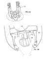
- FIG. 8A is a perspective view of a cross-section of the movable head and the screw and the collet, in the absence of the distal portion of the movable head.
- FIG. 8B is a perspective view of a cross-section of the movable head and the screw and the collet, in the presence of the distal portion of the movable head.
- FIGS. 8C, 8D, 8E and 8F are various views, nearly along the axis, of assemblies similar to those of FIGS. 8A and 8B .
- FIG. 9A is a perspective view of only the distal portion of the movable head, having two sub-motion-limiters.
- FIG. 11 is a perspective view similar to FIG. 10 , but from a different viewing angle.
- FIG. 12 is a perspective view similar to FIG. 11 but showing two sub-motion-limiters about to slide into place, from yet another viewing angle.
- FIG. 13A is a perspective view of a sub-motion-limiter.
- FIG. 13B is a perspective view of a sub-motion-limiter and also a proximal portion, illustrating respective taper angles.
- FIG. 14A is a perspective view of a cross-section of a uniplanar screw assembly.
- FIG. 14B is a close-up view of a portion of FIG. 14A .
- FIG. 15 is a three-dimensional perspective view of a sub-motion-limiter and also a collet in a typical position relative to the sub-motion-limiter.
- FIGS. 16A-16G are three-dimensional perspective cross-sectional illustrations which show sequential steps in the assembly of a screw of an embodiment.
- FIG. 17A is a three-dimensional perspective view of a screw assembly of an embodiment, together with a spinal rod.
- FIG. 17B is a cross-section of FIG. 17A , along 17 B- 17 B.
- FIG. 18A is a three-dimensional perspective view of a screw of another disclosed embodiment
- FIGS. 18B and 18C are side views of the embodiment shown in FIG. 18A .
- FIGS. 19A, 19B, and 19C are three-dimensional perspective views of the proximal portion of a movable head of an embodiment, each from a different vantage point.
- FIG. 19D is a three-dimensional perspective view of the distal portion of the movable head, suitable to connect to the proximal portion of the movable head shown in FIG. 19C .
- FIG. 20 is a three-dimensional perspective view showing the movable head shown in FIG. 19B and the bottom cap shown in FIG. 19C joined together.
- FIGS. 21A and 21B are three-dimensional perspective views of a top-cap piece.
- FIG. 22A is a three-dimensional cross-sectional view of an assembly of a disclosed embodiment.
- FIG. 22B is a three-dimensional cross-sectional view of the assembly shown in FIG. 22A from a different perspective.
- FIG. 23 is a three-dimensional perspective view showing only the movable head and the screw head.
- FIG. 24 is a three-dimensional perspective view showing only the screw head and the movable head distal portion.
- FIGS. 25A-25D are three-dimensional perspective cross-sectional views of the apparatus in sequential stages of assembly.
- FIG. 26 is a three-dimensional perspective view of an embodiment of a screw.
- FIG. 27A is a perspective view of the movable head of the embodiment shown in FIG. 26 .
- FIG. 27B shows the embodiment of FIG. 27A with the two motion limiters omitted for clarity.
- FIG. 27C shows the embodiment of FIG. 27A with the movable head omitted for clarity.
- FIG. 27D is a perspective view of an embodiment of a motion limiter.
- FIGS. 27E and 27F are perspective views of one embodiment of a motion limiter being inserted into an embodiment of a movable head, while the other motion limiter is already in place in the movable head.
- FIG. 28 is a composite view of the embodiment of a screw shown in FIG. 26 showing multiple possible positions of the screw shaft relative to the movable head.
- FIG. 29A is a three-dimensional perspective view of a screw with a first design of certain external features of the movable head.
- FIG. 29B is a three-dimensional perspective view of a screw with a second design of certain external features of the movable head.
- FIG. 30A is a three-dimensional perspective view of an embodiment that provides D-planar motion.
- FIG. 30B is a three-dimensional perspective view of the embodiment shown in FIG. 30A , with only the movable head shown for clarity.
- FIG. 30C is a similar view to that of FIG. 30B .
- FIG. 30D is a view similar to that of FIG. 30B .
- FIG. 31A is a three-dimensional perspective view of the embodiment shown in FIG. 30A , but with the screw shaft shown in multiple positions superimposed on each other to illustrate a range of motion.
- FIG. 31B is similar to FIG. 31A .
- FIG. 32A is a three-dimensional perspective view of an embodiment of a collet.
- FIG. 32B is a top view of the embodiment shown in FIG. 32A .
- FIG. 32C is a perspective view of an embodiment of a screw apparatus with the embodiment of the collet shown in FIGS. 32A and 32B .
- an embodiment provides a screw 100 that may possess a shaft 110 , and a screw head 130 that may be integral with or attached to the shaft 110 .
- the screw head 130 may be a portion of a sphere or have a spheroidal shape.
- the apparatus may further be provided with a collet 200 that may fit around all or a portion of the screw head 130 .
- the apparatus may further have a movable head 300 , which may in turn fit around the collet 200 .
- screw 100 may possess threads 120 around shaft 110 .
- Screw head 130 may also have, at its end opposite shaft 110 , a tool interface recess 136 (see, e.g., FIGS. 16C-16F ) that may be a hexalobe feature.
- Screw 100 may have a longitudinal axis 140 .
- the longitudinal axis 140 generally extends through the center of the screw 100 along its length.
- the screw shaft 110 may be either solid (as illustrated) or alternatively may be hollow, with the empty central region being available for other purposes as may be desired.
- the screw 100 including the screw head 130 , may be axisymmetric about longitudinal axis 140 .
- a collet 200 having a generally ring shape defining a central opening 208 and a longitudinal axis 240 .
- the collet 200 may have a first or top end at a proximal end 202 of the collet 200 and a second or bottom end at a distal end 204 of the collet 200 .
- the collet longitudinal axis 240 extends through the center of the collet 200 from a proximal end 202 to a distal end 204 of the collet 200 .
- the collet 200 may have slots 210 that may be provided in an alternating pattern around the circumference.
- Such a slot pattern may provide the collet 200 with the ability to elastically deflect in any of various directions.
- the collet 200 may, within certain limits, be deformable radially inwardly and may be deformable radially outwardly. Bending or twisting of the collet 200 in various directions may also be permitted.
- the collet 200 may, when in an undeformed state, have a collet inner surface 220 that may be partially spherical and may resemble a portion of the external surface of the screw head 130 .
- the collet inner surface 220 does not need to exactly match the external surface of the screw head 130 .
- the collet inner surface 220 may be concave with a less tight curvature (that is, a larger radius of curvature) than the spherical portion of the screw head 130 .
- the collet inner surface 220 and the screw head 130 may be related to each other such that when the collet 200 is constrained against outward radial deformation, the screw head 130 is prevented from sliding distally with respect to the collet 200 , such as by a wedging action.
- the inside surface of the collet 200 may have an inside radius (measured from centerline axis 240 ) of R1 near the proximal end 202 , and may have another inside radius R2, and may have a third inside radius R3 near the distal end 204 .
- R2 may be measured somewhere between the measurement locations of R1 and R3.
- R2 may be the largest radius of the three radii.
- the exterior of the collet 200 may have an external taper 201 or curvature such that the collet exterior is narrower toward the distal end 204 of the collet 200 as compared to the proximal end 202 of the collet 200 .
- the collet 200 may have a collet external surface 230 , which may resemble an internal surface 325 of the movable head 300 . At least a portion of the collet external surface 230 may be frustoconical. In FIG. 2B , the overall included angle of the external taper of collet 200 is labeled using the designation a (alpha). However, the collet external surface 230 need not exactly match internal surface 325 of movable head 300 or any other internal surface of the movable head 300 .
- the collet 200 may be capable of deforming radially outwardly so as to receive the screw head 130 , and may be capable of springing radially inwardly after the screw head 130 is in an appropriate place inside the collet 200 .
- the collet 200 and screw head 130 may be related such that when the collet 200 fits around the screw head 130 in the absence of movable head 300 , with no external forces being applied, the collet 200 is snug against the screw head 130 resulting in friction between the collet 200 and screw head 130 .
- the collet 200 and screw head 130 may be related such that when the collet 200 fits around the screw head 130 in the presence of movable head 300 in the fully-assembled configuration but without a spinal rod tightened into place, the collet 200 is snug against the screw head 130 resulting in friction between the collet 200 and the screw head 130 .
- This friction may be such that the movable head 300 can be placed in any desired position relative to the screw 100 within the range of permitted motion and will remain in that position at least against gravitational forces acting on the various parts of the screw assembly (i.e., the individual weight of the various parts) in any orientation.
- the friction may be greater than what is needed simply to maintain a position of the screw 100 , relative to the movable head 300 , against gravitational forces.
- the collet 200 may further have an external lip 250 at or near its proximal end. Such an external lip 250 may extend farther outwardly in a radial direction than the rest of the collet 200 .
- the external lip 250 may be interrupted by the slots 210 just as nearby parts of the collet 200 , other than the external lip 250 , are interrupted by the slots 210 .
- movable head 300 may have a proximal end 302 and a distal end 304 and a generally longitudinal axis 340 from the proximal end 302 to the distal end 304 through the center of the movable head 300 .
- the movable head 300 may also have a first or top portion or end and a second or bottom portion or end, whereby the top portion is located at a proximal end 302 of the movable head 300 and the bottom portion is located at a distal end 304 of the movable head 300 .
- the movable head 300 may have an internal thread 310 at its proximal end 302 .
- the movable head 300 may also have, at its proximal end 302 , a U-shaped passageway or U-trough 360 through the movable head 300 .
- the U-trough 360 may have an axis generally perpendicular to the longitudinal axis 340 of the movable head.
- the U-trough 360 axis may also be generally transverse through the movable head 300 .
- the movable head 300 may have a hole 365 therethrough at its distal end or bottom portion.
- the movable head 300 distal end 304 may have an internal surface 320 located between the internal thread 310 and the hole 365 at the distal end 304 .
- the internal surface 320 may be generally concave and may be at least partially spherical or generally spheroidal in shape.
- the movable head 300 may have an internal lip 350 between the internal surface 320 and the internal thread 340 .
- the movable head 300 may also have an internal tapered region 325 , which may be frusto-conical and may be at least somewhat complementary to the external surface 230 of the collet 200 .
- any of a variety of interface features 390 a , 390 b for interfacing with a tool or instrument may be provided on each of two opposed sides of the movable head 300 .
- the interface features 390 a , 390 b may be identical to each other or symmetrical to each other about a common plane or axis, or, alternatively, there may be design differences between the interface features 390 a and 390 b . It is possible that either or both of the interface features 390 a , 390 b may have an undercut so as to provide a slip-resistant interface with the instrument or tool. As is illustrated most particularly in FIG.
- such an undercut may have a cross-sectional shape that is trapezoidal, with base 391 a , the longer of the two parallel sides of the trapezoid and being closer to the longitudinal axis 340 of the movable head 300 than is opening 391 b , the shorter of the two parallel sides.
- the interface features 390 a , 390 b may have an external interface centering feature 392 that is located at a plane of symmetry of the movable head 300 .
- the external interface centering feature may be a depression or may be a recess in a direction different from other portions of the interface features 390 a , 390 b.
- Movable head 300 may also possess a proximal portion or component 370 and a distal portion or component 380 , as described in more detail elsewhere herein.
- the apparatus may further be provided with a set screw 500 that may have an external thread 540 that engages with the internal thread 310 of the movable head 300 .
- the apparatus may further be provided with a saddle 580 to form an interface between the set screw 500 and a rod 400 (described elsewhere herein).
- the saddle 580 may be captured by or attached to set screw 500 in such a way as to form a single assembly together with the set screw 500 . However, even when captured or assembled, the saddle 580 may be able to rotate with respect to the set screw 500 .
- Such capturing or assembly connection may be either loose or frictional as desired.
- the rod-facing surface 590 of the saddle 580 may be either smooth or textured as desired.
- the external shape of the saddle 580 may be such that the saddle 580 can only be slid into the movable head 300 at certain angular positions, which may correspond to desired thread-starting positions.
- FIGS. 5A and 5B These various components are shown in FIGS. 5A and 5B in a configuration in which the components have been assembled, but the apparatus is not yet tightened so as to hold a spinal rod. This may be referred to as a nominal assembled configuration. It is noted that, as illustrated in FIGS. 5A and 5B , the collet 200 is not as far advanced toward the distal end of the apparatus as it would eventually be when a rod 400 is in place and tightened. Also as illustrated in FIGS. 5A and 5B , the collet 200 is positioned such that the external lip 250 of the collet 200 is just slightly distal of the internal lip 350 of the movable head 300 (also shown in FIG. 16D-16F ).
- FIGS. 6A-6C a configuration of the apparatus is provided showing the position of the screw with respect to the movable head 300 , with a screw assembly of an embodiment tightened to grasp a spinal rod 400 .
- the illustrated apparatus shows the screw 100 is able to rotate with respect to the movable head 300 around the longitudinal axis 140 of the screw 100 .
- the apparatus may be such that the screw 100 is able to rotate about the longitudinal axis 140 without constraint, i.e., even more than one full rotation if desired. It is possible, although it is not wished to be limited to this example, that when such motion occurs, the screw head 130 rotates with respect to the collet 200 while the collet 200 remains stationary with respect to the movable head 300 . However, it is also possible that the opposite may happen, i.e., the screw head 130 and the collet 200 could rotate as a unit with respect to the movable head 300 . Furthermore, it is even possible that some rotation at each interface could occur.
- the apparatus may be configured such that it permits, within certain limits, angulation of the screw 100 with respect to movable head 300 .
- the limits of angulation may be such as to define a space of permitted angles that make up a shape which is not a cone.
- the limits of angulation may be defined quite specifically by the shape of the edges of the distal portion 380 of the movable head 300 (such as sub-motion-limiters 382 , 384 ).
- Angulation limits may be defined with respect to each of two different planes or rotational axes, which may be mutually perpendicular to each other. These amounts of angulation may be, and preferably are, different from each other. As illustrated in FIG. 6B and FIG.
- a baseline position of the movable head 300 relative to the screw longitudinal axis 140 such that the longitudinal axis 340 of the movable head 300 might, when in this baseline position, coincide with the screw longitudinal axis 140 , as is illustrated in FIGS. 8A, 8B and 12 .
- This baseline position may also be such that the screw is in all respects in the middle of the range of permitted angulation positions. However, it is not essential that the longitudinal axis of the movable head 300 coincide with the middle of the range of angulation. If desired, it may also be possible to design the screw assemblies such that the baseline position of the movable head axis 340 is biased. In other words, the baseline position does not have to be coincident with the screw longitudinal axis 140 at the middle of the range of angulation.
- the movable head 300 may be provided with a proximal portion or component 370 and a distal portion or component 380 that may be assembled to each other for purposes of achieving limits of angulation of the screw shaft 130 .
- distal portion 380 could be made as a single component if appropriate provision is made for joining the distal portion 380 to the proximal portion 370 .
- the distal portion 380 if made as a single component, might be welded to the proximal portion 370 but without the benefit of a mechanical interlock, i.e., with the weld being the major path for transferring mechanical load from distal portion 380 to proximal portion 370 .
- the distal opening may be such as to permit angulation within defined limits within a first plane and essentially forbid angulation in a second plane that is perpendicular to the first plane.
- the distal opening may be such as to permit a defined amount angulation in a first plane and permit only a relatively smaller defined amount of angulation in a second plane that is perpendicular to the first plane.
- FIG. 8A shows proximal portion 370 and the screw head 130 , but distal portion 380 is not shown.
- FIG. 8B shows proximal portion 370 , distal portion 380 and the screw head 130 .
- FIGS. 8C-8F show, for purposes of illustration, the arrangement of movable head 300 and the screw 100 , with the collet 200 omitted for clarity of illustration. These illustrations are views approximately along the axis 140 of the screw 100 .
- FIGS. 8C and 8D are views looking from the proximal end to the distal end, and FIGS. 8E and 8F are views from the distal end to the proximal end. In FIG.
- the sub-motion-limiters 382 , 384 are omitted and it can be observed that there is empty space completely around the screw head 130 between the movable head 300 and the screw head 130 , which illustrates that the screw head 130 has an unrestricted path to come up into the movable head 300 for assembly purposes.
- FIG. 8E the same situation is visible in FIG. 8E from a different vantage point.
- FIG. 8D the two sub-motion-limiters 382 , 384 are present, and a small visible portion of sub-motion-limiters 382 , 384 is highlighted.
- FIG. 8C the sub-motion-limiters 382 , 384 are omitted and it can be observed that there is empty space completely around the screw head 130 between the movable head 300 and the screw head 130 , which illustrates that the screw head 130 has an unrestricted path to come up into the movable head 300 for assembly purposes.
- FIG. 8D the two sub-motion-limiters 382 , 384 are present, and
- sub-motion-limiters 382 , 384 are visible in their entirety, and therefore empty space is visible at only some places around the circumference of the screw head 130 , but is not visible around the entire circumference of the screw head 130 .
- empty space is visible between the movable head 300 and the screw head 130 in two places but not all the way around the circumference. The empty space which is visible is related to the range of permitted motion. The places where empty space is not visible are related to the trapping of the screw head 130 within movable head 300 .
- the sub-motion-limiters 382 , 384 may contribute to trapping the screw head 130 within the movable head 300 , although the collet 200 (not present in FIG. 8C-8F ) may also be involved in direct contact with the screw head 130 .
- the distal portion 380 may be provided with two sub-motion-limiters 382 , 384 which together make up distal portion 380 .
- the sub-motion-limiters 382 , 384 may be identical to each other, or symmetric to each other about a common plane that generally lies between the sub-motion-limiters 382 , 384 so that each one makes one-half of distal portion 380 .
- Such subdividing of distal portion 380 into sub-motion-limiters 382 , 384 may be done such as to facilitate assembly as discussed elsewhere herein.
- the sub-motion-limiter 382 is adapted to slide, along a direction of sliding insertion, into a receiving feature in the proximal portion 370 of the movable head 300 .
- the direction of sliding insertion is generally parallel to an axis through the U-trough 360 (an axis generally following a longitudinal axis of rod 400 as shown at least in FIG. 6A ), and also generally perpendicular to the longitudinal axis 340 of the movable head 300 .
- FIG. 10 is a perspective view, in which sub-motion-limiter 382 is positioned some distance behind the movable head 300 .
- the sub-motion-limiter 382 appears narrower in width than a corresponding dovetail feature in the movable head 300 .
- the design of the sub-motion-limiter 382 and the design of the proximal portion 370 may be such that the sub-motion-limiter 382 is mechanically captured within the proximal portion 370 . Such geometry could thereby restrain the sub-motion-limiter 382 against possible motion or forces along the longitudinal axis 340 of the movable head 300 , such as forces that would act to separate the sub-motion-limiter 382 from the proximal portion 370 .
- the interaction between sub-motion-limiter 382 and proximal portion 370 may have a dovetail joint.
- the sub-motion-limiter 382 (or 384 ) may have a taper such that the sub-motion-limiter 382 is wider at its proximal end and narrower at its distal end, and the proximal portion 370 of the movable head 300 may have a complementary taper, such as, for example, a dovetail feature 372 .
- the sub-motion-limiter 382 (or 384 ) and the proximal portion 370 may form a dovetail joint connection capable of resisting separation that could be caused by forces applied to the distal portion 380 along the longitudinal axis 340 of the movable head 300 .
- a shelf relationship such as a shelf or step joint, could also be used for the same purpose.
- Clips or other retention features could be provided so that when the sub-motion-limiter 382 (or 384 ) is in place in the proximal portion 370 it is discouraged from coming out of place. It would also be possible that there be a press fit between any of the relevant components to retain the components in place. Similarly, it would be possible that some deformation is required to occur in order for the components to be assembled. Welding, such as laser-welding, could also be used in attachment of sub-motion-limiter 382 (or 384 ) to the proximal portion 370 either in addition to the described mechanical interlock, or in place thereof.
- FIG. 11 also illustrates the ability of the sub-motion-limiter 382 to slide into the proximal portion 370 , but viewed from a different perspective.
- FIG. 12 also illustrates this, but shows both sub-motion-limiters 382 and 384 as if they were about to slide into place (also showing the screw 100 already in position).
- FIGS. 13A and 13B there is further illustrated the possible taper or dovetail relationship between sub-motion-limiter 382 or 384 , and proximal portion 370 , particularly dovetail 372 .
- FIG. 13A is a view of sub-motion-limiter 382 , showing the taper angle.
- FIG. 13B is a view of sub-motion-limiter 382 and also proximal portion 370 with taper angles identified on both pieces. It can be seen that the taper angles on the respective pieces 382 and 370 are equal to each other or, more generally, are almost equal to each other.
- the distal portion 380 or sub-motion-limiters 382 , 384 may have a recess 394 suitable to provide space for a portion of the collet 200 . If there are sub-motion-limiters 382 , 384 , each of the sub-motion-limiters may have such a recess.
- the recess 394 may be such that when all the components are assembled, there is a gap between the most-distal end surface of the collet 200 and the facing surface of the recess 394 in the sub-motion-limiter.
- the collet 200 may find its tightened position as determined by the wedging of the collet 200 external surface against the internal surface of distal portion 380 (sub-motion-limiters 382 , 384 ) of movable head 300 . It is also illustrated in FIG. 15 that the sub-motion-limiters 382 , 384 may have a stop feature 388 that cooperates with the proximal portion 370 to determine how far towards the centerline 340 the sub-motion-limiters 382 , 384 are allowed to slide.
- the stop feature 388 may determine the final position of sub-motion-limiters 382 , 384 relative to proximal portion 370 , especially in a direction along the direction of motion by which sub-motion-limiters slide into their final position in proximal portion 370 .
- the various parts may fit together such that in a fully assembled and tightened condition, a force from the set screw 500 is exerted (possibly through the saddle 580 ) onto a spinal rod 400 , which in turn exerts force onto the proximal end surface 250 of the collet 200 which urges the collet 200 farther into the tapering interior of proximal portion 370 .
- This may create a wedging action involving the interior of the proximal portion 370 , the collet 200 , and the screw head 130 .
- Such a wedging action may lock all of the relevant components into a fixed position.
- the apparatus may further have a joint, such as, for example, a weld for joining the sub-motion-limiter 382 , 384 and the proximal portion 370 , but such joint need not carry all of the force transmitted through the joint because of the presence of a dovetail relationship or similar supporting relationship between the sub-motion-limiter 382 , 384 and proximal portion 370 .
- a joint such as, for example, a weld for joining the sub-motion-limiter 382 , 384 and the proximal portion 370 .
- the apparatus may have features that provide for mechanically trapping the collet 200 within the movable head 300 when the collet 200 is deeper than a certain point within the movable head 300 .
- the internal lip 350 may be such as to interact with the external lip 250 of the collet 200 so as to trap the collet 200 inside the movable head 300 .
- the external lip 250 of the collet 200 may pass by the internal lip 350 , as the collet 200 moves toward the distal end of the movable head 300 , it may be possible for the external lip 250 and the collet 200 , in general, to deform radially inwardly towards the longitudinal axis 240 of the collet 200 .
- the external lip 250 may spring radially outwardly. This outwardly springing action may trap the collet 200 inside the movable head 300 , or at least may help to define a preferred or maintained position of the collet 200 relative to the movable head 300 when the collet 200 is in that region of the movable head 300 .
- the apparatus may be such that the screw (particularly the screw head 130 ) may be loaded into the movable head proximal portion 370 from the distal end when the distal portion 380 or the sub-motion-limiters 382 , 384 are absent from the apparatus. More specifically, the diameter of the sphere of the screw head 130 may be smaller than an opening in the distal end of the movable head 300 , when the distal portion 380 or the sub-motion-limiters 382 , 384 are absent from the apparatus.
- the dimensions of the various components may further be such that when the distal portion 380 or the sub-motion-limiters 382 , 384 are together with the rest of polyaxial the screw head 300 , the sphere of the screw head 130 cannot fit through the distal end opening of the apparatus. It is further possible that the sphere of the screw head 130 may be too large to fit through the opening in the proximal end of the proximal portion 370 .
- Dimensional interrelationships among the various components may be such that, when the distal portion 380 is absent, the screw head 130 may be able to pass upwardly through the opening 365 in the distal end of the proximal portion 370 of the movable head 300 . Furthermore, when the distal portion 380 is in place connected to the proximal portion 370 of the movable head 300 , the screw head 130 may be unable to pass through the opening in the distal portion 380 ; but the screw shaft 110 is able to pass through the hole in the distal portion 380 . It is possible that the screw head 130 is unable to pass through the most proximal end of the collet 200 (the end having lip 250 ) when the collet 200 is in place inside the movable head 300 .
- the collet 200 may be able to enter the movable head 300 through the open proximal end of the movable head 300 .
- the proximal portion 370 of the movable head 300 is provided without its distal portion 380 .
- the collet 200 is introduced through the proximal end 302 of the proximal portion 370 of the movable head 300 .
- the collet 200 is brought partially into the movable head 300 but is stopped before external lip 250 of the collet 200 passes the internal lip 350 of the movable head 300 . This may be termed a screw-receiving position of the collet 200 .
- the screw head 130 With reference to FIG. 16C , with the collet 200 in the screw-receiving position, the screw head 130 is brought up through the distal end 304 opening of the movable head 300 . The screw head 130 is brought into the collet internal space where it is received, which requires some elastic deformation of the collet 200 .
- the collet 200 with the screw head 130 already received inside it, is then advanced farther distally into the movable head 300 so that the external lip 250 of the collet 200 passes the internal lip 350 of the movable head 300 , and the collet 200 reaches its assembled position, in which the collet external lip 250 is more distal than the internal lip 350 .
- sub-motion-limiters 382 , 384 are brought into position at the distal end of the movable head 300 . Because the bottom shoulder has sub-motion-limiters 382 , 384 , one sub-motion-limiter can be brought in from each of two opposed directions. If the sub-motion-limiters and the main body of the movable head 300 are related by means of a dovetail or mechanical interlocking relationship, this feature may provide mechanical support. For clarity of illustration, the proximal portion 370 and the screw 100 are shown sectioned, but the sub-motion-limiters 382 , 384 are shown in their entirety. It is also illustrated in FIG. 16E that the sub-motion-limiters 382 , 384 may have a stop feature 388 that cooperates with the screw shaft 110 to limit the motion of the screw shaft 110 relative to the movable head 300 .
- the sub-motion-limiters 382 , 384 are joined to the main body of the movable head 300 , such as by welding.
- there may be friction such that the movable head 300 may be placed in any desired position relative to the screw 100 , within the range of permitted motion, and will remain in that position at least against gravitational forces acting on the various parts of the screw assembly (i.e., the individual weight of the various parts), in any orientation.
- the friction may be greater than what is needed simply to maintain a position against gravitational forces.
- the spinal rod 400 when the assembly is being implanted into a patient and a spinal rod 400 is being clamped by tightening of set screw 500 pressing against spinal rod, the spinal rod may press against the top of the collet 200 , which may further urge the collet 200 or the screw head 130 or both into a final-tightened position, which may be advanced farther distally within the movable head 300 as compared to the assembled position.
- the spinal rod 400 is not shown.
- the position of the collet 200 along the proximal-distal direction can be judged, for example, by the position of the collet lip 250 relative to the bottom of the U-trough 360 or relative to the internal lip 350 . These positions differ from FIG. 16F to FIG. 16G .
- the final clamped position is also illustrated in FIGS. 17A and 17B .
- a detail concerning the final-tightened position relates to the collet 200 having an angular position around its own longitudinal axis 240 , which may be arbitrary, with respect to the movable head 300 .
- the spinal rod 400 presses against the external lip 250 of the collet 200 , or that the spinal rod presses against the gap 210 in the external lip 250 of the collet 200 .
- the choice of lip contact or gap contact can make a slight difference in the actual axial position of the collet 200 , along its own axis 240 , when the whole assembly is tightened. However, the difference will not be very large.
- the spinal rod 400 may bear against the lip 250 of the collet 200 and may be out of contact with the screw head 130 . Clamping of the screw head 130 may be achieved by frictional gripping of the collet 200 against the screw head 130 .
- other options may also be possible.
- the sub-motion-limiters 382 , 384 may have a recess therein for receiving a portion of the collet 200 .
- the collet 200 need not bear against the recess in distal portion 380 or sub-motion-limiters 382 , 384 , but the recess 394 may nevertheless be provided to allow space that can be occupied by a portion of the collet 200 .
- FIGS. 17A and 17B there is further shown the assembly of the components of all previous Figures.
- FIG. 17A there is shown the previous assembly having the screw 100 , the collet 200 and the movable head 300 , together with a segment of a rod 400 , such as a spinal rod, seated in the movable head 300 .
- a set screw 500 is tightened against rod 400
- rod 400 bears against the proximal surface of the collet 200 . It is possible that there may be differences in position of the collet 200 between a nominal assembled configuration and a final tightened configuration.
- the collet 200 may be more deeply (more distally) located within the movable head 300 than is the case for the nominal assembled configuration.
- the collet 200 may undergo some elastic deformation. However, this is dependent on design details and is optional.
- the rod 400 may also touch the bottom of the U-trough 360 , but that is optional and depends on design details.
- the rod 400 does not touch the upper surface of the screw head 130 .
- yet another embodiment may achieve uniplanar motion using a different embodiment than as previously disclosed in which the screw head possesses a pair of flat surfaces rather than being generally axisymmetric about its own centroidal axis as in the embodiment previously described.
- This alternate embodiment may be provided with a screw 1100 .
- the screw 1100 may have a shaft 1110 and a screw head 1130 integral with or joined to the shaft 1110 .
- the screw 1100 may have a longitudinal axis 1140 .
- the screw head 1130 may have a portion of a sphere but furthermore may have two planar surfaces 1188 that may be opposed to each other.
- the planar surfaces 1188 may be parallel to each other and may be equally spaced on opposite sides of the longitudinal axis of shaft of the screw 1100 .
- the embodiment may further provide a movable head 1300 .
- the movable head 1300 may have a proximal portion 1700 and a distal portion 1800 that may be connected to or joined to each other or may be suitable to attach to each other.
- the proximal portion 1700 of the movable head 1300 may have a U-trough 1360 therethrough suitable to receive a spinal rod.
- the proximal portion 1700 of the movable head 1300 may also have an axial opening 1365 extending from its proximal end to its distal end.
- the axial opening 1365 may merge with the open space of the U-trough 1360 .
- the axial opening 1365 may be large enough for the screw head 1130 to pass through the distal end of proximal portion 1700 .
- the axial opening 1365 may be non-circular. Portions of the axial opening 1365 may be suitable to interact with the planar surfaces 1188 of the screw head 1130 .
- the distal portion 1800 of the movable head 1300 may have an internal surface that is dimensioned suitably to bear against and retain the distal-facing surface of the screw head 1130 .
- the distal portion 1800 of the movable head 1300 may have an opening 1865 therethrough, through which the screw head 1130 is unable to pass. This opening 1865 may be circular as illustrated, although it could be non-circular if desired.
- the opening 1865 facing distally may have a chamfer or other transitional feature.
- the distal portion 1800 of the movable head 1300 may be such as to limit angulation of the screw 1100 with respect to the movable head 1300 .
- the distal portion 1800 of the movable head 1300 may be axisymmetric about its own centroidal axis.
- the apparatus may further have a force-transmitting cap 1900 .
- the force-transmitting cap 1900 may have a distal surface 1920 that is at least partially spherical and compatible with the spherical external surface of the screw head 1130 .
- the force-transmitting cap 1900 may have a proximal surface 1930 that is at least partially cylindrically compatible with a cylindrical spinal rod.
- the force-transmitting cap 1900 may possess a hole 1965 therethrough that generally connects the distal surface 1920 and the proximal surface 1910 .
- the hole 1965 may be of larger diameter or cross-sectional dimension than an instrument-receiving interface 1136 in the screw 1100 .
- the force-transmitting cap 1900 may have side surfaces 1950 a , 1950 b that may be substantially flat and parallel and suitable to fit between corresponding surfaces of the proximal portion of the movable head 1300 .
- the force-transmitting cap 1900 may further be provided with a shoulder 1642 , and the proximal portion of the movable head 1300 may possess a recess suitable to receive the shoulder 1642 of force-transmitting cap 1900 .
- the force-transmitting cap 1900 may in some dimension be larger than axial opening through the distal portion 1800 of the movable head 1300 .
- the force-transmitting cap 1900 may be trapped and unable to exit proximally because of the shoulder causing it to be trapped within the proximal portion 1400 of the movable head 1300 , and unable to exit distally because of being trapped by the distal portion 1800 of the movable head 1300 .
- the various components may be such that a set screw engages threads in the proximal portion 1700 of the movable head 1300 and presses on the spinal rod, which in turn presses on the force-transmitting cap 1900 , which in turn presses on the screw head 1130 . Forces from the screw head 1130 are in turn reacted by the distal portion 1800 of the movable head 1300 , which is in turn connected to the proximal portion 1700 of the movable head 1300 .
- the spinal rod to exert force directly on the force-transmitting cap 1900 , which in turn exerts force on the screw head 1300 , to lock the position of the screw 1100 with respect to the movable head 1300 .
- the flat sides 1188 of the screw head 1130 are also visible. Flat sides 1188 interact with corresponding flat surfaces in proximal portion 1700 to limit angulation of the screw head 1130 in a certain degree of freedom of motion.
- FIG. 25A-25D show steps of assembly of the apparatus of this embodiment.
- FIG. 25A shows only the proximal portion 1700 of the movable head 1300 as a first step of assembly.
- FIG. 25B shows the proximal portion 1700 of the movable head 1300 , together with the force-transmitting cap 1900 .
- the force-transmitting cap 1900 is introduced into proximal portion 1700 through the distal end of proximal portion 1700 , and is not able to travel all the way through the proximal portion 1700 , so that it later becomes trapped within the assembly.
- FIG. 25A shows only the proximal portion 1700 of the movable head 1300 as a first step of assembly.
- FIG. 25B shows the proximal portion 1700 of the movable head 1300 , together with the force-transmitting cap 1900 .
- the force-transmitting cap 1900 is introduced into proximal portion 1700 through the distal end of proximal portion 1700
- FIG. 25C shows the proximal portion 1700 of the movable head 1300 together with the force-transmitting cap 1900 and the screw 1100 .
- FIG. 25D shows the components already illustrated in FIG. 25C , together with the distal portion 1800 joined to proximal portion 1700 .
- the joining of the distal portion 1800 to proximal portion 1700 traps the screw head 1130 and also traps the force-transmitting cap 1900 .
- the grooves 2372 , 2374 may have a longitudinal axis that may be generally parallel to a longitudinal axis of the U-trough 2360 that extends through the movable head 2300 , and may also be generally parallel to the longitudinal axis of the spinal rod 400 that would be received within the U-trough 360 of the movable head 300 . As illustrated, there is one groove 2372 , 2374 on each side of the mid-plane of the movable head 2300 , and the two grooves 2372 , 2374 are substantially parallel to each other. Groove 2372 and groove 2374 may be symmetric about a common plane to each other.
- a first motion limiter 2382 may be generally long and located within groove 2372 and located entirely on one side of the plane that is a mid-plane of the movable head 2300 , corresponding to the spinal rod 400 .
- a second motion limiter 2384 may be generally long and located entirely on the other side of the plane in groove 2374 .
- the first motion limiter 2382 and the second motion limiter 2384 may be symmetric about a common plane to each other.
- the respective grooves 2372 , 2374 in the movable head 2300 may comprise dovetail features, and the motion limiters 2382 , 2384 may have external taper features corresponding to a dovetail joint.
- the grooves 2372 , 2374 may be wider at the top than at the bottom (in the orientation shown), and the motion limiters 2382 , 2384 may be wider at the top than at the bottom (in the orientation shown).
- the taper angle of the dovetail feature of the groove 2372 , 2374 is illustrated in FIG. 27B
- a taper angle of the motion limiter 2382 , 2384 is illustrated in FIG. 27C . These two taper angles may be equal to each other, although it is not necessary that they be exactly equal to each other.
- a weld could be created, such as by laser welding, electron beam welding or any other suitable form of welding, at any suitable location where an edge or surface of motion limiter 2382 , 2384 is close to an edge or surface of movable head 2300 , and where such edges or surfaces are physically accessible for deposition of energy during welding. Such welding may be performed either with or without adding of additional material during welding.
- a primary retention mechanism or load path that comprises the interaction between the grooves 2372 , 2374 , and the motion limiters 2382 , 2384 in the manner of physical trapping so as to resist or prevent downward motion of the motion limiters 2382 , 2384 with respect to the movable head 2300
- a secondary retention mechanism that comprises the weld or the joining of the motion limiters 2382 , 2384 to the movable head 2300
- the weld or adhesive or joining or similar securing mechanism may anchor the motion limiters 2382 , 2384 in place with respect to the longitudinal direction of the groove 2372 , 2374 and the longitudinal direction of the motion limiters 2382 , 2384 .
- the weld or adhesive or joining or similar securing mechanism may further serve some role, although not necessarily a major role, in the actual transfer of load between the motion limiter 2382 , 2384 and the movable head 2300 .
- FIG. 27A shows a movable head 2300 containing two motion limiters 2382 , 2384 , in a three-dimensional view from slightly below the movable head 2300 .
- FIG. 27B is an illustration similar to FIG. 27A , except that the motion limiters 2382 , 2384 are removed.
- FIG. 27C there are illustrated two motion limiters 2382 , 2384 as they would be positioned in the assembled movable head 2300 , but for clarity of illustration the body of the movable head 2300 is omitted so that only the two motion limiters 2382 , 2384 are shown.
- each motion limiter 2382 , 2384 corresponds to complementary features of the dovetail features of the grooves 2372 , 2374 .
- FIG. 27D shows a single motion limiter 2372 in a different orientation suitable to show certain features of the motion limiter 2372 .
- motion limiter 2372 may have, and is illustrated as having, a flat edge 2388 . This edge 2388 or a corner associated with it may interact with shaft 2110 of screw 2100 .
- FIG. 27E and FIG. 27F show the movable head 2300 together with one motion limiter 2384 that is in place and the other motion limiter 2382 that is displaced along the direction of motion according to which motion limiter 2382 would be advanced into slot 2372 .
- FIG. 27E which is a perspective view
- the viewing direction is along the direction of advancement
- motion limiter 2382 is displaced far enough back to provide an apparent difference in size due to perspective.
- FIG. 27F which is a view more from below, motion limiter 2382 is displaced only to the point where it begins to make contact with movable head 2300 .
- One or both of the motion limiters 2382 , 2384 may have an edge 2388 that faces the shaft 2110 of the screw 2100 , and that edge 2388 may determine the geometry of motion limitation imposed on the screw 2100 .
- edge 2388 may determine the geometry of motion limitation imposed on the screw 2100 .
- the allowable range of motion of the shaft 2110 of the screw 2100 may be substantially within a plane as illustrated, i.e., what is referred to as uniplanar.
- the movable head design shown in FIG. 29A has an external cross-section that is roughly cylindrical in cross-section (taken perpendicular to the longitudinal axis of the movable head), and the movable head design shown in FIG. 29B has an external cross-section that is roughly rounded-square in cross-section (taken perpendicular to the longitudinal axis of the movable head).
- the movable head design shown in FIG. 29A has an instrument interface feature that is a simple racetrack-shaped recess 2391 , while the movable head design shown in FIG.
- 29B has an instrument interface that comprises a dovetail groove 2390 A, 2390 B (not to be confused with the dovetail groove 2372 , 2374 that receives the motion limiters 2382 , 2384 ).
- the movable head design shown in FIG. 29A might be manufactured of a titanium alloy, while the movable head design shown in FIG. 29B might be manufactured of a stainless steel alloy.
- a movable head 3300 assembled to a screw 3100 having shaft 3110 that defines a space of allowable positions for the screw shaft that has a boundary that is not a simple circular boundary.
- Such perimeter of the boundary that defines or limits the motion of the screw shaft 3110 with respect to the movable head 3300 may be defined by a portion that is a straight line and a portion that is a curve. Such a curve may be a portion of a circle.
- FIGS. 31A and 31B Such a range of allowable positions of the screw shaft is illustrated in FIGS. 31A and 31B .
- Such a range of motion may be achieved by a movable head 3300 that has a motion-limiting edge such that for a portion of the motion-limiting perimeter there is provided a motion limiter 3384 , which may provide a straight-line limiting edge if desired, while for another portion of the on the opposite side of the mid-plane, the motion of the screw shaft 3110 with respect to the movable head 3300 may be defined by an edge that is or includes a portion of a circle.
- the straight-line portion of the motion-defining edge on one side of the mid-plane of the movable head 3300 may be defined by a motion limiter 3384
- the portion of the motion-limiting edge that is a portion of a circle may be defined by the body of the movable head 3300 with no presence of a separate motion limiter.
- the motion limiter 3384 which may occur on only one side of the movable head 3300 but not the other side, may be similar to the motion limiter 2382 , 2384 described elsewhere herein.
- motion limiter 3384 (or similarly, 2382 , 2384 ), which has been illustrated here as having an edge that is straight, could have an edge that is some other shape. The same may be true for the sub-motion-limiters 382 , 384 described elsewhere herein.
- FIG. 30 what is illustrated as the D-planar design has a movable head that substantially corresponds to the first design, FIG. 29A , rather than the second design in FIG. 29B .
- the D-planar features of FIG. 30 could similarly be used with the second design or with any other design details of the movable head 3300 .
- FIG. 31A and FIG. 31B illustrate a range of possible positions of the shaft 3110 with respect to the movable head 3300 , for the D-planar design of FIG. 30 .
- a collet 3200 as illustrated in FIG. 32A and FIG. 32B .
- this collet 3200 it may be helpful to understand that in a movable-head screw that contains a collet surrounding the spherical screw head, it is possible that the angular orientation of collet 3200 with respect to movable head 3300 , with respect to the longitudinal axis of the collet 3200 , may be unknown. Even if the assembly may be assembled with the collet in a known angular orientation, it may be unclear if the collet will always remain in that same orientation.
- a spinal rod 400 may rest on the solid portion of the lip 3250 , or alternatively it is possible that a spinal rod 400 may sit on the gap that may occur at a slot in the collet.
- the collet may have at one end a lip 3250 , or, whether or not a lip is present, may have a flat surface at one end.
- the collet may be provided with slots 3212 entering from a first or proximal end of the collet and slots 3214 entering from a second or distal end of the collet.
- slots 3212 entering from a first or proximal end of the collet
- slots 3214 entering from a second or distal end of the collet.
- gaps in the lip or flat surface there may be seen gaps in the lip or flat surface. The number of those gaps may be an odd number, so that it is not possible for the spinal rod to simultaneously contact gaps at one location on the lip 3250 of the collet 3200 and also a diametrically opposed location on lip 3250 .
- the gaps 3212 at the end of the collet that has the lip 3250 may be oriented in a non-radial direction. It is further possible that the width of the gap 3212 , the thickness of the lip 3250 in a radial direction, and the angular orientation of the gap 3212 , interact with each other such that any radial line (representing a line of possible contact with spinal rod 400 ) has to intersect at least a portion of the lip 3250 .
- the number of slots entering from the first end may be different from the number of slots entering from the second end.
- the number of slots 3214 entering from the distal end or the end that does not have the lip 3250 may be greater than the number of slots 3212 entering from the proximal end or the end that has the lip 3250 or flat surface.
- the number of slots 3214 entering from the end that does not have the lip 3250 may be twice the number of slots 3212 entering from the end that does have the lip 3250 .
- collet 3200 described herein could be used with any of the screw embodiments described herein.
- embodiments of the invention have been illustrated comprising a collet that provides friction to retain positioning of the screw shaft with respect to the movable head, it would also be possible to create a similar screw assembly that does not have a collet or friction by omitting the collet.
- Embodiments of the invention have been described herein having a dovetail relationship between the motion limiter and the movable head, specifically the groove within the movable head.
- a dovetail joint is just one of various possible geometries that allow the motion limiter to slide in to the movable head.
- a step joint having generally perpendicular sides, which may be referred to as a shelf or shelf joint, could be used.
- a proximal dimension of the motion limiter or sub-motion-limiter be greater than a corresponding distal dimension of the groove in which the motion limiter or sub-motion-limiter occupies.
- This provides a mechanical support or interlock to prevent the motion limiter or sub-motion-limiter from being urged out of the movable head.
- such mechanical support can be supplemented by a joining such as welding.
- the screw 100 is able to be rotated arbitrarily about its own longitudinal axis 140 with respect to the movable head 300 .
- any screw described herein may be cannulated, such as for accommodating a K-wire or for delivery of a liquid such as cement to the interior bone region. If cannulation of the screw is provided, fenestration of the walls of the screw is also possible.
- inventive embodiments are presented by way of example only and that, within the scope of the appended claims and equivalents thereto; inventive embodiments may be practiced otherwise than as specifically described and claimed.
- inventive embodiments of the present disclosure are directed to each individual feature, system, article, material, kit, and/or method described herein.
- a reference to “A and/or B”, when used in conjunction with open-ended language such as “comprising” can refer, in one embodiment, to A only (optionally including elements other than B); in another embodiment, to B only (optionally including elements other than A); in yet another embodiment, to both A and B (optionally including other elements); etc.
- the phrase “at least one,” in reference to a list of one or more elements, should be understood to mean at least one element selected from any one or more of the elements in the list of elements, but not necessarily including at least one of each and every element specifically listed within the list of elements and not excluding any combinations of elements in the list of elements.
- This definition also allows that elements may optionally be present other than the elements specifically identified within the list of elements to which the phrase “at least one” refers, whether related or unrelated to those elements specifically identified.
- “at least one of A and B” can refer, in one embodiment, to at least one, optionally including more than one, A, with no B present (and optionally including elements other than B); in another embodiment, to at least one, optionally including more than one, B, with no A present (and optionally including elements other than A); in yet another embodiment, to at least one, optionally including more than one, A, and at least one, optionally including more than one, B (and optionally including other elements); etc.
Abstract
Description
Claims (8)
Priority Applications (6)
| Application Number | Priority Date | Filing Date | Title |
|---|---|---|---|
| US14/797,702 US9707014B1 (en) | 2010-07-09 | 2015-07-13 | Apparatus and method for limiting a range of angular positions of a screw |
| US15/449,460 US10206717B1 (en) | 2010-07-09 | 2017-03-03 | Apparatus and method for limiting a range of angular positions of a screw |
| US15/730,418 US10603083B1 (en) | 2010-07-09 | 2017-10-11 | Apparatus and method for limiting a range of angular positions of a screw |
| US16/278,549 US11213324B2 (en) | 2010-07-09 | 2019-02-18 | Apparatus and method for limiting a range of angular positions of a screw |
| US16/834,556 US11147594B1 (en) | 2010-07-09 | 2020-03-30 | Apparatus and method for limiting a range of angular positions of a screw |
| US17/564,615 US20220117635A1 (en) | 2010-07-09 | 2021-12-29 | Apparatus and Method for Limiting a Range of Angular Positions of a Screw |
Applications Claiming Priority (3)
| Application Number | Priority Date | Filing Date | Title |
|---|---|---|---|
| US36299310P | 2010-07-09 | 2010-07-09 | |
| US13/180,332 US9084634B1 (en) | 2010-07-09 | 2011-07-11 | Uniplanar screw |
| US14/797,702 US9707014B1 (en) | 2010-07-09 | 2015-07-13 | Apparatus and method for limiting a range of angular positions of a screw |
Related Parent Applications (1)
| Application Number | Title | Priority Date | Filing Date |
|---|---|---|---|
| US13/180,332 Continuation US9084634B1 (en) | 2010-07-09 | 2011-07-11 | Uniplanar screw |
Related Child Applications (1)
| Application Number | Title | Priority Date | Filing Date |
|---|---|---|---|
| US15/449,460 Division US10206717B1 (en) | 2010-07-09 | 2017-03-03 | Apparatus and method for limiting a range of angular positions of a screw |
Publications (1)
| Publication Number | Publication Date |
|---|---|
| US9707014B1 true US9707014B1 (en) | 2017-07-18 |
Family
ID=53540039
Family Applications (5)
| Application Number | Title | Priority Date | Filing Date |
|---|---|---|---|
| US13/180,332 Active 2033-02-03 US9084634B1 (en) | 2010-07-09 | 2011-07-11 | Uniplanar screw |
| US14/797,702 Active US9707014B1 (en) | 2010-07-09 | 2015-07-13 | Apparatus and method for limiting a range of angular positions of a screw |
| US15/449,460 Active US10206717B1 (en) | 2010-07-09 | 2017-03-03 | Apparatus and method for limiting a range of angular positions of a screw |
| US16/278,549 Active 2031-07-23 US11213324B2 (en) | 2010-07-09 | 2019-02-18 | Apparatus and method for limiting a range of angular positions of a screw |
| US17/564,615 Pending US20220117635A1 (en) | 2010-07-09 | 2021-12-29 | Apparatus and Method for Limiting a Range of Angular Positions of a Screw |
Family Applications Before (1)
| Application Number | Title | Priority Date | Filing Date |
|---|---|---|---|
| US13/180,332 Active 2033-02-03 US9084634B1 (en) | 2010-07-09 | 2011-07-11 | Uniplanar screw |
Family Applications After (3)
| Application Number | Title | Priority Date | Filing Date |
|---|---|---|---|
| US15/449,460 Active US10206717B1 (en) | 2010-07-09 | 2017-03-03 | Apparatus and method for limiting a range of angular positions of a screw |
| US16/278,549 Active 2031-07-23 US11213324B2 (en) | 2010-07-09 | 2019-02-18 | Apparatus and method for limiting a range of angular positions of a screw |
| US17/564,615 Pending US20220117635A1 (en) | 2010-07-09 | 2021-12-29 | Apparatus and Method for Limiting a Range of Angular Positions of a Screw |
Country Status (1)
| Country | Link |
|---|---|
| US (5) | US9084634B1 (en) |
Cited By (8)
| Publication number | Priority date | Publication date | Assignee | Title |
|---|---|---|---|---|
| US20160262810A1 (en) * | 2015-03-09 | 2016-09-15 | Alphatec Spine, Inc. | Transverse link having spherical ball joint |
| US20170290608A1 (en) * | 2016-01-22 | 2017-10-12 | Spinal Usa, Inc. | Spinal fixation systems and methods |
| US20180193062A1 (en) * | 2017-01-11 | 2018-07-12 | Warsaw Orthopedic, Inc | Spinal implant system and methods of use |
| US10206717B1 (en) | 2010-07-09 | 2019-02-19 | Theken Spine, Llc | Apparatus and method for limiting a range of angular positions of a screw |
| US20190142474A1 (en) * | 2005-05-10 | 2019-05-16 | Roger P. Jackson | Polyaxial bone anchor with compound articulation and pop-on shank |
| US10507043B1 (en) | 2017-10-11 | 2019-12-17 | Seaspine Orthopedics Corporation | Collet for a polyaxial screw assembly |
| US10603083B1 (en) | 2010-07-09 | 2020-03-31 | Theken Spine, Llc | Apparatus and method for limiting a range of angular positions of a screw |
| US11076888B2 (en) | 2017-07-28 | 2021-08-03 | Anza Innovations, Inc. | Spinal stabilization system including bottom loading wide angulation polyaxial rod anchor assemblies |
Families Citing this family (25)
| Publication number | Priority date | Publication date | Assignee | Title |
|---|---|---|---|---|
| KR20100087334A (en) * | 2007-10-24 | 2010-08-04 | 너바시브 인코퍼레이티드 | Surgical fixation system and related methods |
| US8337530B2 (en) * | 2011-03-09 | 2012-12-25 | Zimmer Spine, Inc. | Polyaxial pedicle screw with increased angulation |
| US9993269B2 (en) * | 2011-07-15 | 2018-06-12 | Globus Medical, Inc. | Orthopedic fixation devices and methods of installation thereof |
| US20190247094A1 (en) * | 2011-07-15 | 2019-08-15 | Globus Medical, Inc. | Orthopedic fixation devices and methods of installation thereof |
| US10918419B2 (en) | 2014-04-01 | 2021-02-16 | K2M, Inc. | Spinal fixation device |
| US9993270B2 (en) * | 2014-07-18 | 2018-06-12 | Warsaw Orthopedic, Inc. | Bone fastener and methods of use |
| US10028770B2 (en) * | 2014-10-20 | 2018-07-24 | Warsaw Orthopedic, Inc. | Spinal implant system and methods of use |
| CN104799931B (en) * | 2015-04-13 | 2017-07-07 | 李贵涛 | Nest mortar rail chain type replacement and fixation dynamic pedicle screw system |
| US20170020573A1 (en) * | 2015-07-20 | 2017-01-26 | Amendia, Inc. | Pedicle screw tulip assembly with multi-segmented member |
| US10874438B2 (en) | 2016-07-13 | 2020-12-29 | Medos International Sarl | Bone anchor assemblies and related instrumentation |
| US10363073B2 (en) | 2016-07-13 | 2019-07-30 | Medos International Sàrl | Bone anchor assemblies and related instrumentation |
| US10568667B2 (en) | 2016-07-13 | 2020-02-25 | Medos International Sàrl | Bone anchor assemblies and related instrumentation |
| US10463402B2 (en) | 2016-07-13 | 2019-11-05 | Medos International Sàrl | Bone anchor assemblies and related instrumentation |
| USD879965S1 (en) * | 2017-05-16 | 2020-03-31 | Wiltrom Co., Ltd. | Pedicle screw |
| USD879299S1 (en) * | 2017-05-24 | 2020-03-24 | Wiltrom Co., Ltd. | Spinal screw |
| US10610265B1 (en) | 2017-07-31 | 2020-04-07 | K2M, Inc. | Polyaxial bone screw with increased angulation |
| US10966762B2 (en) | 2017-12-15 | 2021-04-06 | Medos International Sarl | Unilateral implant holders and related methods |
| US11291482B2 (en) | 2019-03-21 | 2022-04-05 | Medos International Sarl | Rod reducers and related methods |
| US11291481B2 (en) | 2019-03-21 | 2022-04-05 | Medos International Sarl | Rod reducers and related methods |
| USD1004774S1 (en) | 2019-03-21 | 2023-11-14 | Medos International Sarl | Kerrison rod reducer |
| US11684395B2 (en) | 2019-05-22 | 2023-06-27 | Nuvasive, Inc. | Posterior spinal fixation screws |
| DE102019116374A1 (en) * | 2019-06-17 | 2020-12-17 | Aesculap Ag | Partially blocked pedicle screw II |
| US11399965B2 (en) | 2019-09-09 | 2022-08-02 | Warsaw Orthopedic, Inc. | Spinal implant system and methods of use |
| EP3878386B1 (en) * | 2020-03-12 | 2023-08-30 | Biedermann Technologies GmbH & Co. KG | Coupling device for use with a bone anchoring element and bone anchoring device with such a coupling device |
| USD956233S1 (en) * | 2020-04-24 | 2022-06-28 | Solco Biomedical Co., Ltd. | Cervical screw |
Citations (282)
| Publication number | Priority date | Publication date | Assignee | Title |
|---|---|---|---|---|
| US2699774A (en) | 1952-05-12 | 1955-01-18 | Livingston Herman Harrison | Bone pin locking device |
| US4653481A (en) | 1985-07-24 | 1987-03-31 | Howland Robert S | Advanced spine fixation system and method |
| US4719905A (en) | 1985-11-01 | 1988-01-19 | Acromed Corporation | Apparatus and method for maintaining vertebrae in a desired relationship |
| US4805602A (en) | 1986-11-03 | 1989-02-21 | Danninger Medical Technology | Transpedicular screw and rod system |
| US4950269A (en) | 1988-06-13 | 1990-08-21 | Acromed Corporation | Spinal column fixation device |
| US5053036A (en) | 1987-11-03 | 1991-10-01 | Synthes (U.S.A.) | Point contact bone compression plate |
| US5085660A (en) | 1990-11-19 | 1992-02-04 | Lin Kwan C | Innovative locking plate system |
| US5108395A (en) | 1989-09-18 | 1992-04-28 | Societe De Fabrication De Materiel Orthopedique - Sofamor | Implant for anterior dorsolumbar spinal osteosynthesis, intended for the correction of kyphoses |
| US5112332A (en) | 1988-12-21 | 1992-05-12 | Zimmer, Inc. | Method of performing spinal surgery |
| US5116334A (en) | 1988-12-21 | 1992-05-26 | Zimmer, Inc. | Posterior spinal system and method |
| US5152303A (en) | 1991-06-18 | 1992-10-06 | Carl Allen | Anterolateral spinal fixation system and related insertion process |
| US5154719A (en) | 1990-02-19 | 1992-10-13 | Societe De Fabrication De Materiel Orthopedique - Sofamor | Implant for a device for osteosynthesis, in particular of the spine |
| US5181917A (en) | 1990-06-19 | 1993-01-26 | Chaim Rogozinski | System and method for instrumentation of the spine in the treatment of spinal deformities |
| US5196013A (en) | 1989-11-03 | 1993-03-23 | Harms Juergen | Pedicel screw and correcting and supporting apparatus comprising such screw |
| US5207678A (en) | 1989-07-20 | 1993-05-04 | Prufer | Pedicle screw and receiver member therefore |
| US5261911A (en) | 1991-06-18 | 1993-11-16 | Allen Carl | Anterolateral spinal fixation system |
| US5281223A (en) | 1992-09-21 | 1994-01-25 | Ray R Charles | Tool and method for derotating scoliotic spine |
| US5324290A (en) | 1992-09-24 | 1994-06-28 | Danek Medical, Inc. | Anterior thoracolumbar plate |
| US5330473A (en) | 1993-03-04 | 1994-07-19 | Advanced Spine Fixation Systems, Inc. | Branch connector for spinal fixation systems |
| US5380325A (en) | 1992-11-06 | 1995-01-10 | Biomat | Osteosynthesis device for spinal consolidation |
| US5382248A (en) | 1992-09-10 | 1995-01-17 | H. D. Medical, Inc. | System and method for stabilizing bone segments |
| US5403314A (en) | 1993-02-05 | 1995-04-04 | Acromed Corporation | Apparatus for retaining spinal elements in a desired spatial relationship |
| US5443467A (en) | 1993-03-10 | 1995-08-22 | Biedermann Motech Gmbh | Bone screw |
| US5466237A (en) | 1993-11-19 | 1995-11-14 | Cross Medical Products, Inc. | Variable locking stabilizer anchor seat and screw |
| US5474555A (en) | 1990-04-26 | 1995-12-12 | Cross Medical Products | Spinal implant system |
| US5480401A (en) | 1993-02-17 | 1996-01-02 | Psi | Extra-discal inter-vertebral prosthesis for controlling the variations of the inter-vertebral distance by means of a double damper |
| US5486176A (en) | 1991-03-27 | 1996-01-23 | Smith & Nephew Richards, Inc. | Angled bone fixation apparatus |
| US5501684A (en) | 1992-06-25 | 1996-03-26 | Synthes (U.S.A.) | Osteosynthetic fixation device |
| US5549608A (en) | 1995-07-13 | 1996-08-27 | Fastenetix, L.L.C. | Advanced polyaxial locking screw and coupling element device for use with rod fixation apparatus |
| US5554157A (en) | 1995-07-13 | 1996-09-10 | Fastenetix, L.L.C. | Rod securing polyaxial locking screw and coupling element assembly |
| US5584834A (en) | 1995-07-13 | 1996-12-17 | Fastenetix, L.L.C. | Polyaxial locking screw and coupling element assembly for use with side loading rod fixation apparatus |
| US5586984A (en) | 1995-07-13 | 1996-12-24 | Fastenetix, L.L.C. | Polyaxial locking screw and coupling element assembly for use with rod fixation apparatus |
| US5591235A (en) | 1995-03-15 | 1997-01-07 | Kuslich; Stephen D. | Spinal fixation device |
| US5591165A (en) | 1992-11-09 | 1997-01-07 | Sofamor, S.N.C. | Apparatus and method for spinal fixation and correction of spinal deformities |
| US5601552A (en) | 1994-03-18 | 1997-02-11 | Sofamor, S.N.C. | Fixing device for a rigid transverse connection device between rods of a spinal osteosynthesis system |
| US5615965A (en) | 1992-11-10 | 1997-04-01 | Sofamor S.N.C. | Device for interconnecting an elongate element and a support for said element |
| US5620443A (en) | 1995-01-25 | 1997-04-15 | Danek Medical, Inc. | Anterior screw-rod connector |
| US5669911A (en) | 1995-04-13 | 1997-09-23 | Fastenetix, L.L.C. | Polyaxial pedicle screw |
| US5672176A (en) | 1995-03-15 | 1997-09-30 | Biedermann; Lutz | Anchoring member |
| US5681319A (en) | 1995-03-01 | 1997-10-28 | Biedermann; Lutz | Locking tool |
| US5683391A (en) | 1995-06-07 | 1997-11-04 | Danek Medical, Inc. | Anterior spinal instrumentation and method for implantation and revision |
| US5713900A (en) | 1996-05-31 | 1998-02-03 | Acromed Corporation | Apparatus for retaining bone portions in a desired spatial relationship |
| US5716356A (en) | 1994-07-18 | 1998-02-10 | Biedermann; Lutz | Anchoring member and adjustment tool therefor |
| US5725527A (en) | 1992-09-10 | 1998-03-10 | Biedermann Motech Gmbh | Anchoring member |
| US5728098A (en) | 1996-11-07 | 1998-03-17 | Sdgi Holdings, Inc. | Multi-angle bone screw assembly using shape-memory technology |
| US5733285A (en) | 1995-07-13 | 1998-03-31 | Fastenetix, Llc | Polyaxial locking mechanism |
| US5738685A (en) | 1993-05-18 | 1998-04-14 | Schafer Micomed Gmbh | Osteosynthesis device |
| US5752957A (en) | 1997-02-12 | 1998-05-19 | Third Millennium Engineering, Llc | Polyaxial mechanism for use with orthopaedic implant devices |
| US5782833A (en) | 1996-12-20 | 1998-07-21 | Haider; Thomas T. | Pedicle screw system for osteosynthesis |
| US5797911A (en) | 1996-09-24 | 1998-08-25 | Sdgi Holdings, Inc. | Multi-axial bone screw assembly |
| US5800435A (en) | 1996-10-09 | 1998-09-01 | Techsys, Llc | Modular spinal plate for use with modular polyaxial locking pedicle screws |
| US5863293A (en) | 1996-10-18 | 1999-01-26 | Spinal Innovations | Spinal implant fixation assembly |
| US5879350A (en) | 1996-09-24 | 1999-03-09 | Sdgi Holdings, Inc. | Multi-axial bone screw assembly |
| US5882350A (en) | 1995-04-13 | 1999-03-16 | Fastenetix, Llc | Polyaxial pedicle screw having a threaded and tapered compression locking mechanism |
| US5885286A (en) | 1996-09-24 | 1999-03-23 | Sdgi Holdings, Inc. | Multi-axial bone screw assembly |
| US5888221A (en) | 1992-08-11 | 1999-03-30 | Gelbard; Steven D. | Spinal stabilization implant system |
| US5891145A (en) | 1997-07-14 | 1999-04-06 | Sdgi Holdings, Inc. | Multi-axial screw |
| US5910142A (en) | 1998-10-19 | 1999-06-08 | Bones Consulting, Llc | Polyaxial pedicle screw having a rod clamping split ferrule coupling element |
| US5925047A (en) | 1998-10-19 | 1999-07-20 | Third Millennium Engineering, Llc | Coupled rod, anterior vertebral body screw, and staple assembly |
| US5964760A (en) | 1996-10-18 | 1999-10-12 | Spinal Innovations | Spinal implant fixation assembly |
| US5989254A (en) | 1997-05-20 | 1999-11-23 | Katz; Akiva Raphael | Pedicle screw assembly |
| US5997539A (en) | 1997-05-15 | 1999-12-07 | Spinal Concepts, Inc. | Polyaxial pedicle screw having a compression locking rod gripping mechanism |
| US6010503A (en) | 1998-04-03 | 2000-01-04 | Spinal Innovations, Llc | Locking mechanism |
| US6017344A (en) | 1997-05-15 | 2000-01-25 | Spinal Concepts, Inc. | Polyaxial pedicle screw having a through bar clamp locking mechanism |
| US6019759A (en) | 1996-07-29 | 2000-02-01 | Rogozinski; Chaim | Multi-Directional fasteners or attachment devices for spinal implant elements |
| US6022350A (en) | 1996-05-13 | 2000-02-08 | Stryker France S.A. | Bone fixing device, in particular for fixing to the sacrum during osteosynthesis of the backbone |
| US6048343A (en) | 1999-06-02 | 2000-04-11 | Mathis; John M. | Bone screw system |
| WO2000019923A1 (en) | 1998-10-06 | 2000-04-13 | Surgical Dynamics, Inc. | Device for securing spinal rods |
| US6050997A (en) | 1999-01-25 | 2000-04-18 | Mullane; Thomas S. | Spinal fixation system |
| US6063090A (en) | 1996-12-12 | 2000-05-16 | Synthes (U.S.A.) | Device for connecting a longitudinal support to a pedicle screw |
| US6074391A (en) | 1997-06-16 | 2000-06-13 | Howmedica Gmbh | Receiving part for a retaining component of a vertebral column implant |
| US6090111A (en) | 1998-06-17 | 2000-07-18 | Surgical Dynamics, Inc. | Device for securing spinal rods |
| US6113601A (en) | 1998-06-12 | 2000-09-05 | Bones Consulting, Llc | Polyaxial pedicle screw having a loosely coupled locking cap |
| US6132430A (en) | 1996-10-24 | 2000-10-17 | Spinal Concepts, Inc. | Spinal fixation system |
| US6146383A (en) | 1998-02-02 | 2000-11-14 | Sulzer Orthopadie Ag | Pivotal securing system at a bone screw |
| US6183473B1 (en) | 1999-04-21 | 2001-02-06 | Richard B Ashman | Variable angle connection assembly for a spinal implant system |
| US6187005B1 (en) | 1998-09-11 | 2001-02-13 | Synthes (Usa) | Variable angle spinal fixation system |
| US6206879B1 (en) | 1998-10-22 | 2001-03-27 | Aesculap Ag & Co. Kg | Osteosynthetic holding system |
| US6210376B1 (en) | 1999-04-08 | 2001-04-03 | New York University | Cannulated delivery pin |
| US6214006B1 (en) | 1992-03-02 | 2001-04-10 | Howmedica Gmbh | Apparatus for bracing vertebrae |
| US6214012B1 (en) | 1998-11-13 | 2001-04-10 | Harrington Arthritis Research Center | Method and apparatus for delivering material to a desired location |
| US6226548B1 (en) | 1997-09-24 | 2001-05-01 | Surgical Navigation Technologies, Inc. | Percutaneous registration apparatus and method for use in computer-assisted surgical navigation |
| US20010001119A1 (en) | 1999-09-27 | 2001-05-10 | Alan Lombardo | Surgical screw system and related methods |
| US6248105B1 (en) | 1997-05-17 | 2001-06-19 | Synthes (U.S.A.) | Device for connecting a longitudinal support with a pedicle screw |
| US6254602B1 (en) | 1999-05-28 | 2001-07-03 | Sdgi Holdings, Inc. | Advanced coupling device using shape-memory technology |
| WO2001052758A1 (en) | 2000-01-19 | 2001-07-26 | Surgical Dynamics, Inc. | Device for securing spinal rods |
| US6273888B1 (en) | 1999-05-28 | 2001-08-14 | Sdgi Holdings, Inc. | Device and method for selectively preventing the locking of a shape-memory alloy coupling system |
| US6280443B1 (en) | 1999-01-30 | 2001-08-28 | Ja-Kyo Gu | Spinal fixation system |
| US6280442B1 (en) | 1999-09-01 | 2001-08-28 | Sdgi Holdings, Inc. | Multi-axial bone screw assembly |
| US6302888B1 (en) | 1999-03-19 | 2001-10-16 | Interpore Cross International | Locking dovetail and self-limiting set screw assembly for a spinal stabilization member |
| US6309391B1 (en) | 2000-03-15 | 2001-10-30 | Sdgi Holding, Inc. | Multidirectional pivoting bone screw and fixation system |
| US20020010467A1 (en) | 2000-07-22 | 2002-01-24 | Corin Spinal Systems Limited | Pedicle attachment assembly |
| US20020022842A1 (en) | 2000-04-18 | 2002-02-21 | Horvath Andres A. | Medical fastener cap system |
| US20020035366A1 (en) | 2000-09-18 | 2002-03-21 | Reto Walder | Pedicle screw for intervertebral support elements |
| US6361535B2 (en) | 2000-02-16 | 2002-03-26 | Roger P. Jackson | Bone screw threaded plug closure with central set screw |
| US6368321B1 (en) | 2000-12-04 | 2002-04-09 | Roger P. Jackson | Lockable swivel head bone screw |
| US6371957B1 (en) | 1997-01-22 | 2002-04-16 | Synthes (Usa) | Device for connecting a longitudinal bar to a pedicle screw |
| US6375657B1 (en) | 2000-03-14 | 2002-04-23 | Hammill Manufacturing Co. | Bonescrew |
| US20020058942A1 (en) | 2000-11-10 | 2002-05-16 | Biedermann Motech Gmbh | Bone screw |
| US20020082602A1 (en) | 2000-12-22 | 2002-06-27 | Lutz Biedermann | Fixing element |
| US6413257B1 (en) | 1997-05-15 | 2002-07-02 | Surgical Dynamics, Inc. | Clamping connector for spinal fixation systems |
| US20020091386A1 (en) | 2001-01-05 | 2002-07-11 | Greg Martin | Pedicle screw assembly |
| US20020133154A1 (en) | 2001-03-15 | 2002-09-19 | Saint Martin Pierre Henri | Anchoring member with safety ring |
| US6454768B1 (en) | 2000-12-05 | 2002-09-24 | Roger P. Jackson | Removable gripping set screw |
| US20020138076A1 (en) | 2000-12-27 | 2002-09-26 | Biederman Motech Gmbh | Screw |
| US6458132B2 (en) | 2000-03-15 | 2002-10-01 | Gil-Woon Choi | Spine supporting system |
| US20020143341A1 (en) | 2001-03-27 | 2002-10-03 | Lutz Biedermann | Anchoring element |
| US20020151900A1 (en) | 2001-01-12 | 2002-10-17 | Craig Glascott | Polyaxial screw with improved locking |
| US6471705B1 (en) | 1999-08-02 | 2002-10-29 | Lutz Biedermann | Bone screw |
| US6475218B2 (en) | 2000-06-30 | 2002-11-05 | Sofamor, S.N.C. | Spinal implant for an osteosynthesis device |
| US6485491B1 (en) | 2000-09-15 | 2002-11-26 | Sdgi Holdings, Inc. | Posterior fixation system |
| US20030023243A1 (en) | 2001-07-27 | 2003-01-30 | Biedermann Motech Gmbh | Bone screw and fastening tool for same |
| US20030032957A1 (en) | 2001-08-13 | 2003-02-13 | Mckinley Laurence M. | Vertebral alignment and fixation assembly |
| US6547790B2 (en) | 2000-08-08 | 2003-04-15 | Depuy Acromed, Inc. | Orthopaedic rod/plate locking mechanisms and surgical methods |
| US20030073997A1 (en) | 2001-10-17 | 2003-04-17 | Doubler Robert L. | Split ring bone screw for a spinal fixation system |
| US20030073996A1 (en) | 2001-10-17 | 2003-04-17 | Doubler Robert L. | Split ring bone screw for a spinal fixation system |
| US6554832B2 (en) | 2001-04-02 | 2003-04-29 | Endius Incorporated | Polyaxial transverse connector |
| US6554834B1 (en) | 1999-10-07 | 2003-04-29 | Stryker Spine | Slotted head pedicle screw assembly |
| US20030083657A1 (en) | 2001-10-30 | 2003-05-01 | Drewry Troy D. | Flexible spinal stabilization system and method |
| US20030100896A1 (en) | 2001-11-27 | 2003-05-29 | Lutz Biedermann | Element with a shank and a holding element connected to it for connecting to a rod |
| US20030100904A1 (en) | 2001-11-27 | 2003-05-29 | Lutz Biedermann | Locking device for securing a rod-shaped element in a holding element connected to a shank |
| US6582436B2 (en) | 1998-09-29 | 2003-06-24 | Synthes (U.S.A.) | Device for connecting a longitudinal support to a bone anchor |
| US20030125741A1 (en) | 2001-12-28 | 2003-07-03 | Biedermann Motech Gmbh | Locking device for securing a rod-shaped element in a holding element connected to a shank |
| US20030149431A1 (en) | 2002-02-01 | 2003-08-07 | Varieur Michael S. | Closure system for spinal fixation instrumentation |
| US20030158552A1 (en) | 2001-10-31 | 2003-08-21 | Chang-Hun Jeon | Bone fixation apparatus |
| US6613050B1 (en) | 1996-10-24 | 2003-09-02 | Spinal Concepts, Inc. | Method and apparatus for spinal fixation |
| US6626906B1 (en) | 2000-10-23 | 2003-09-30 | Sdgi Holdings, Inc. | Multi-planar adjustable connector |
| US20030187442A1 (en) | 2002-03-12 | 2003-10-02 | Marc Richelsoph | Bone plate and screw retaining mechanism |
| US20030187439A1 (en) | 2002-03-27 | 2003-10-02 | Biedermann Motech Gmbh | Bone anchoring device for stabilizing bone segments and seat part of a bone anchoring device |
| US20030199873A1 (en) | 2002-04-18 | 2003-10-23 | Marc Richelsoph | Screw and rod fixation assembly and device |
| US6652526B1 (en) | 2001-10-05 | 2003-11-25 | Ruben P. Arafiles | Spinal stabilization rod fastener |
| US6660006B2 (en) | 2002-04-17 | 2003-12-09 | Stryker Spine | Rod persuader |
| US6689137B2 (en) | 2001-10-15 | 2004-02-10 | Gary Jack Reed | Orthopedic fastener and method |
| US20040030337A1 (en) | 2002-04-09 | 2004-02-12 | Neville Alleyne | Bone fixation apparatus |
| US6692500B2 (en) | 2001-10-15 | 2004-02-17 | Gary Jack Reed | Orthopedic stabilization device and method |
| US6702817B2 (en) | 2001-01-19 | 2004-03-09 | Aesculap Ag & Co. Kg | Locking mechanism for a bone screw |
| US6716214B1 (en) | 2003-06-18 | 2004-04-06 | Roger P. Jackson | Polyaxial bone screw with spline capture connection |
| US6730092B2 (en) | 2001-12-03 | 2004-05-04 | Pioneer Laboratories, Inc. | System and method for bone fixation |
| US20040097933A1 (en) | 2002-11-19 | 2004-05-20 | Rodolphe Lourdel | Vertebral anchoring device and its blocking device on a polyaxial screw |
| US20040102781A1 (en) | 2002-11-25 | 2004-05-27 | U & I Corporation | Bone fixation apparatus, method and tool for assembling the same |
| US6755835B2 (en) | 1999-08-14 | 2004-06-29 | Aesculap Ag & Co. Kg | Bone screw |
| US6755829B1 (en) | 2000-09-22 | 2004-06-29 | Depuy Acromed, Inc. | Lock cap anchor assembly for orthopaedic fixation |
| US20040138662A1 (en) | 2002-10-30 | 2004-07-15 | Landry Michael E. | Spinal stabilization systems and methods |
| US20040138660A1 (en) | 2003-01-10 | 2004-07-15 | Serhan Hassan A. | Locking cap assembly for spinal fixation instrumentation |
| US6770075B2 (en) * | 2001-05-17 | 2004-08-03 | Robert S. Howland | Spinal fixation apparatus with enhanced axial support and methods for use |
| US20040158247A1 (en) | 2003-02-07 | 2004-08-12 | Arthit Sitiso | Polyaxial pedicle screw system |
| US6786907B2 (en) | 2001-04-24 | 2004-09-07 | Co-Ligne Ag | Instrumentation for stabilizing certain vertebrae of the spine |
| US20040181224A1 (en) | 2003-03-11 | 2004-09-16 | Biedermann Motech Gmbh | Anchoring element for use in spine or bone surgery, methods for use and production thereof |
| US20040186473A1 (en) | 2003-03-21 | 2004-09-23 | Cournoyer John R. | Spinal fixation devices of improved strength and rigidity |
| US20040186474A1 (en) | 2002-12-02 | 2004-09-23 | Biedermann Motech Gmbh | Implant having a shaft and a holding element connected therewith for connecting with a rod |
| US6800079B2 (en) | 2002-03-15 | 2004-10-05 | Lock-N-Stitch, Inc. | Orthopedic stabilization device and method |
| US6800078B2 (en) | 2001-11-07 | 2004-10-05 | Lock-N-Stitch, Inc. | Orthopedic stabilization device and method |
| US20040225289A1 (en) | 2003-05-07 | 2004-11-11 | Biedermann Motech Gmbh | Dynamic anchoring device and dynamic stabilization device for bones, in particular for vertebrae, with such an anchoring device |
| US20040230192A1 (en) | 2001-07-20 | 2004-11-18 | Henry Graf | Intervertebral linking device |
| US20040236330A1 (en) * | 2003-05-22 | 2004-11-25 | Thomas Purcell | Variable angle spinal screw assembly |
| US20040243126A1 (en) | 2001-09-14 | 2004-12-02 | Stryker Spine | Methods for stabilizing bone using spinal fixation devices |
| US20040249378A1 (en) | 2001-10-04 | 2004-12-09 | Saint Martin Pierre Henri | Spinal osteosynthesis assembly comprising the head of an anchoring member and a tool for fixing said head |
| US20040260283A1 (en) | 2003-06-19 | 2004-12-23 | Shing-Cheng Wu | Multi-axis spinal fixation device |
| US20040260284A1 (en) | 2003-06-23 | 2004-12-23 | Matthew Parker | Anti-splay pedicle screw |
| US20040267264A1 (en) | 2003-06-27 | 2004-12-30 | Konieczynski David D. | Polyaxial bone screw |
| US6837889B2 (en) | 2002-03-01 | 2005-01-04 | Endius Incorporated | Apparatus for connecting a longitudinal member to a bone portion |
| US20050010219A1 (en) | 2003-07-07 | 2005-01-13 | Dalton Brain E. | Bone fixation assembly and method of securement |
| US20050033298A1 (en) | 2001-10-31 | 2005-02-10 | Ortho Development Corporation | Cervical plate for stabilizing the human spine |
| US20050038430A1 (en) | 2003-08-11 | 2005-02-17 | Mckinley Laurence M. | Low profile vertebral alignment and fixation assembly |
| US6858031B2 (en) | 1999-04-16 | 2005-02-22 | Sdgi Holdings, Inc. | Multi-axial bone anchor system |
| US20050049589A1 (en) | 2003-08-28 | 2005-03-03 | Jackson Roger P. | Polyaxial bone screw apparatus |
| US20050049588A1 (en) | 2003-08-28 | 2005-03-03 | Jackson Roger P. | Polyaxial bone screw with split retainer ring |
| US20050055026A1 (en) | 2002-10-02 | 2005-03-10 | Biedermann Motech Gmbh | Bone anchoring element |
| US6869432B2 (en) | 2000-04-19 | 2005-03-22 | Synthes (U.S.A.) | Device for the articulated connection of two bodies |
| US20050070901A1 (en) | 2003-09-26 | 2005-03-31 | Stryker Spine | Bone fixation assembly and method |
| US20050070899A1 (en) | 2003-09-26 | 2005-03-31 | Doubler Robert L. | Polyaxial bone screw with torqueless fastening |
| US20050080415A1 (en) | 2003-10-14 | 2005-04-14 | Keyer Thomas R. | Polyaxial bone anchor and method of spinal fixation |
| US20050080420A1 (en) | 2003-08-20 | 2005-04-14 | Farris Robert A. | Multi-axial orthopedic device and system |
| US20050085812A1 (en) | 2003-10-21 | 2005-04-21 | Sherman Michael C. | Apparatus and method for providing dynamizable translations to orthopedic implants |
| US6896677B1 (en) | 2003-12-11 | 2005-05-24 | A-Spine Holding Group Corp. | Rotary device for retrieving spinal column under treatment |
| US20050119658A1 (en) | 2001-02-15 | 2005-06-02 | K2 Medical Llc | Polyaxial pedicle screw having a rotating locking element |
| US20050137594A1 (en) | 2002-02-04 | 2005-06-23 | Doubler Robert L. | Spinal fixation assembly |
| US20050154391A1 (en) | 2003-12-30 | 2005-07-14 | Thomas Doherty | Bone anchor assemblies |
| US20050154389A1 (en) | 2003-12-16 | 2005-07-14 | Depuy Spine, Inc. | Methods and devices for minimally invasive spinal fixation element placement |
| US20050187548A1 (en) * | 2004-01-13 | 2005-08-25 | Butler Michael S. | Pedicle screw constructs for spine fixation systems |
| US20050187555A1 (en) | 2004-02-24 | 2005-08-25 | Biedermann Motech Gmbh | Bone anchoring element |
| US20050192580A1 (en) | 2004-02-26 | 2005-09-01 | Dalton Brian E. | Polyaxial locking screw plate assembly |
| US20050192573A1 (en) | 2004-02-27 | 2005-09-01 | Custom Spine, Inc. | Biased angle polyaxial pedicle screw assembly |
| US20050192589A1 (en) | 2004-02-06 | 2005-09-01 | Douglas Raymond | Devices and methods for inserting a spinal fixation element |
| US20050192571A1 (en) | 2004-02-27 | 2005-09-01 | Custom Spine, Inc. | Polyaxial pedicle screw assembly |
| US20050203516A1 (en) | 2004-03-03 | 2005-09-15 | Biedermann Motech Gmbh | Anchoring element and stabilization device for the dynamic stabilization of vertebrae or bones using such anchoring elements |
| US20050216003A1 (en) | 2004-03-03 | 2005-09-29 | Biedermann Motech Gmbh | Bone anchoring element for anchoring in a bone or vertebra, and stabilization device with such a bone anchoring element |
| US6951561B2 (en) | 2003-05-06 | 2005-10-04 | Triage Medical, Inc. | Spinal stabilization device |
| US20050228382A1 (en) | 2004-04-12 | 2005-10-13 | Marc Richelsoph | Screw and rod fixation assembly and device |
| US20050228379A1 (en) | 2003-06-18 | 2005-10-13 | Jackson Roger P | Upload shank swivel head bone screw spinal implant |
| US20050240180A1 (en) | 2001-09-03 | 2005-10-27 | Cecile Vienney | Spinal osteosynthesis system comprising a support pad |
| US20050251139A1 (en) | 2004-05-07 | 2005-11-10 | Roh Jeffrey S | Systems and methods that facilitate minimally invasive spine surgery |
| US6964664B2 (en) | 2000-01-06 | 2005-11-15 | Spinal Concepts Inc. | System and method for stabilizing the human spine with a bone plate |
| US6964666B2 (en) | 2003-04-09 | 2005-11-15 | Jackson Roger P | Polyaxial bone screw locking mechanism |
| US20050261687A1 (en) | 2004-04-20 | 2005-11-24 | Laszlo Garamszegi | Pedicle screw assembly |
| US20050267472A1 (en) | 2002-03-27 | 2005-12-01 | Biedermann Motech Gmbh | Bone anchoring device for stabilising bone segments and seat part of a bone anchoring device |
| US20050277923A1 (en) | 2004-06-09 | 2005-12-15 | Sweeney Patrick J | Spinal fixation system |
| US20050277931A1 (en) | 2004-06-09 | 2005-12-15 | Spinal Generations, Llc | Spinal fixation system |
| US20050277928A1 (en) | 2004-06-14 | 2005-12-15 | Boschert Paul F | Spinal implant fixation assembly |
| US20050283157A1 (en) | 2004-06-17 | 2005-12-22 | Coates Bradley J | Multi-axial bone attachment assembly |
| US20060036242A1 (en) | 2004-08-10 | 2006-02-16 | Nilsson C M | Screw and rod fixation system |
| US20060036260A1 (en) | 2004-08-06 | 2006-02-16 | Runco Thomas J | Instrument for guiding a rod into an implant in a spinal fixation system |
| US20060036244A1 (en) | 2003-10-21 | 2006-02-16 | Innovative Spinal Technologies | Implant assembly and method for use in an internal structure stabilization system |
| US20060036252A1 (en) | 2004-08-12 | 2006-02-16 | Baynham Bret O | Polyaxial screw |
| US20060052783A1 (en) | 2004-08-17 | 2006-03-09 | Dant Jack A | Polyaxial device for spine stabilization during osteosynthesis |
| US20060052784A1 (en) | 2004-08-17 | 2006-03-09 | Zimmer Spine, Inc. | Polyaxial device for spine stabilization during osteosynthesis |
| US20060058788A1 (en) | 2004-08-27 | 2006-03-16 | Hammer Michael A | Multi-axial connection system |
| US20060074419A1 (en) | 2004-10-05 | 2006-04-06 | Taylor Harold S | Spinal implants with multi-axial anchor assembly and methods |
| US20060084981A1 (en) | 2004-10-20 | 2006-04-20 | Endius Incorporated | Apparatus for connecting a longitudinal member to a bone portion |
| US20060084979A1 (en) | 2003-04-09 | 2006-04-20 | Jackson Roger P | Polyaxial bone screw with uploaded threaded shank and method of assembly and use |
| US20060084980A1 (en) | 2004-10-05 | 2006-04-20 | Melkent Anthony J | Spinal implants and methods with extended multi-axial anchor assemblies |
| US20060129149A1 (en) | 2004-04-08 | 2006-06-15 | Andrew Iott | Polyaxial screw |
| US20060200128A1 (en) | 2003-04-04 | 2006-09-07 | Richard Mueller | Bone anchor |
| US20060235389A1 (en) * | 2005-03-03 | 2006-10-19 | Accin Corporation | Spinal stabilization using bone anchor and anchor seat with tangential locking feature |
| US7141051B2 (en) | 2003-02-05 | 2006-11-28 | Pioneer Laboratories, Inc. | Low profile spinal fixation system |
| US20070090238A1 (en) | 2005-10-20 | 2007-04-26 | Sdgi Holdings, Inc. | Bottom loading multi-axial screw assembly |
| US20070118123A1 (en) * | 2005-11-21 | 2007-05-24 | Strausbaugh William L | Polyaxial bone anchors with increased angulation |
| US7303562B2 (en) | 1999-12-24 | 2007-12-04 | Sdgi Holdings, Inc. | Pedicle screws with inclined channels to hold support rods |
| US7314467B2 (en) * | 2002-04-24 | 2008-01-01 | Medical Device Advisory Development Group, Llc. | Multi selective axis spinal fixation system |
| US7316684B1 (en) | 1999-07-22 | 2008-01-08 | Stryker Spine | Multiaxial connection for osteosynthesis |
| US7322979B2 (en) | 2000-03-15 | 2008-01-29 | Warsaw Orthopedic, Inc. | Multidirectional pivoting bone screw and fixation system |
| US20080097441A1 (en) | 2004-10-20 | 2008-04-24 | Stanley Kyle Hayes | Systems and methods for posterior dynamic stabilization of the spine |
| US20080161859A1 (en) * | 2006-10-16 | 2008-07-03 | Innovative Delta Technology Llc | Bone Screw and Associated Assembly and Methods of Use Thereof |
| US20080183223A1 (en) | 2005-09-26 | 2008-07-31 | Jeon Dong M | Hybrid jointed bone screw system |
| US20080262556A1 (en) * | 2007-02-27 | 2008-10-23 | Jacofsky Marc C | Modular polyaxial pedicle screw system |
| US7445627B2 (en) | 2005-01-31 | 2008-11-04 | Alpinespine, Llc | Polyaxial pedicle screw assembly |
| US20080312655A1 (en) * | 2007-06-14 | 2008-12-18 | X-Spine Systems, Inc. | Polyaxial screw system and method having a hinged receiver |
| US7476239B2 (en) | 2005-05-10 | 2009-01-13 | Jackson Roger P | Polyaxial bone screw with compound articulation |
| US20090062914A1 (en) | 2007-08-29 | 2009-03-05 | Marino James F | Devices and methods for intervertebral therapy |
| US20090105716A1 (en) * | 2007-10-23 | 2009-04-23 | Michael Barrus | Mono-axial, taper lock bone screw |
| US20090105770A1 (en) | 2007-10-23 | 2009-04-23 | Gregory Berrevoets | Rod Coupling Assembly and Methods for Bone Fixation |
| US20090118772A1 (en) | 2007-06-01 | 2009-05-07 | Jennifer Diederich | Polyaxial bone anchor with increased angulation |
| US7604655B2 (en) | 2004-10-25 | 2009-10-20 | X-Spine Systems, Inc. | Bone fixation system and method for using the same |
| USD603511S1 (en) | 2008-07-03 | 2009-11-03 | Theken Spine, Llc | Cervical plate |
| USD603510S1 (en) | 2008-07-03 | 2009-11-03 | Theken Spine, Llc | Cervical plate |
| USD603508S1 (en) | 2008-07-03 | 2009-11-03 | Theken Spine, Llc | Cervical plate |
| USD603509S1 (en) | 2008-07-03 | 2009-11-03 | Theken Spine, Llc | Cervical plate |
| USD603507S1 (en) | 2008-07-03 | 2009-11-03 | Theken Spine, Llc | Cervical plate |
| USD603506S1 (en) | 2008-07-03 | 2009-11-03 | Theken Spine, Llc | Cervical plate |
| USD603505S1 (en) | 2008-07-03 | 2009-11-03 | Theken Spine, Llc | Cervical plate |
| USD603503S1 (en) | 2008-07-03 | 2009-11-03 | Theken Spine, Llc | Cervical plate |
| USD603504S1 (en) | 2008-07-03 | 2009-11-03 | Theken Spine, Llc | Cervical plate |
| USD603964S1 (en) | 2008-07-03 | 2009-11-10 | Theken Spine, Llc | Cervical plate |
| USD603961S1 (en) | 2008-07-03 | 2009-11-10 | Theken Spine, Llc | Cervical plate |
| USD603962S1 (en) | 2008-07-03 | 2009-11-10 | Theken Spine, Llc | Cervical plate |
| USD603963S1 (en) | 2008-07-03 | 2009-11-10 | Theken Spine, Llc | Cervical plate |
| US7625394B2 (en) | 2005-08-05 | 2009-12-01 | Warsaw Orthopedic, Inc. | Coupling assemblies for spinal implants |
| US7635380B2 (en) | 2007-06-05 | 2009-12-22 | Spartek Medical, Inc. | Bone anchor with a compressor element for receiving a rod for a dynamic stabilization and motion preservation spinal implantation system and method |
| US20100063545A1 (en) * | 2008-09-09 | 2010-03-11 | Richelsoph Marc E | Polyaxial screw assembly |
| US7691129B2 (en) | 2004-10-27 | 2010-04-06 | Felix Brent A | Spinal stabilizing system |
| US20100087873A1 (en) * | 2008-10-06 | 2010-04-08 | Warsaw Orthopedics, Inc. | Surgical Connectors for Attaching an Elongated Member to a Bone |
| US7717941B2 (en) | 2002-09-11 | 2010-05-18 | Spinevision | Linking element for dynamically stabilizing a spinal fixing system and spinal fixing system comprising same |
| US20100125302A1 (en) * | 2008-11-14 | 2010-05-20 | Hammill Sr John E | Locking Polyaxial Ball And Socket Fastener |
| US7766944B2 (en) | 2002-05-21 | 2010-08-03 | Peter Metz-Stavenhagen | Anchoring element for fastening a rod of a device for adjusting a human or animal vertebral column on a vertebra |
| US20100204735A1 (en) * | 2009-02-11 | 2010-08-12 | Gephart Matthew P | Wide Angulation Coupling Members For Bone Fixation System |
| US7780706B2 (en) | 2005-04-27 | 2010-08-24 | Trinity Orthopedics, Llc | Mono-planar pedicle screw method, system and kit |
| US20100249837A1 (en) * | 2009-03-26 | 2010-09-30 | Kspine, Inc. | Semi-constrained anchoring system |
| US7833252B2 (en) | 2006-01-27 | 2010-11-16 | Warsaw Orthopedic, Inc. | Pivoting joints for spinal implants including designed resistance to motion and methods of use |
| US7875065B2 (en) | 2004-11-23 | 2011-01-25 | Jackson Roger P | Polyaxial bone screw with multi-part shank retainer and pressure insert |
| US7892257B2 (en) | 2004-02-27 | 2011-02-22 | Custom Spine, Inc. | Spring loaded, load sharing polyaxial pedicle screw assembly and method |
| US20110054536A1 (en) * | 2008-11-11 | 2011-03-03 | Kspine, Inc. | Growth directed vertebral fixation system with distractible connector(s) and apical control |
| US7931676B2 (en) | 2007-01-18 | 2011-04-26 | Warsaw Orthopedic, Inc. | Vertebral stabilizer |
| US7931678B2 (en) | 2004-12-08 | 2011-04-26 | Depuy Spine, Inc. | Hybrid spinal plates |
| US20110098747A1 (en) * | 2009-04-15 | 2011-04-28 | Synthes Usa, Llc | Arcuate fixation member |
| US7951172B2 (en) * | 2005-03-04 | 2011-05-31 | Depuy Spine Sarl | Constrained motion bone screw assembly |
| US20110178558A1 (en) | 2010-01-15 | 2011-07-21 | Ebi, Llc | Uniplanar bone anchor system |
| US20110178559A1 (en) * | 2010-01-15 | 2011-07-21 | Ebi, Llc | Uniplanar bone anchor system |
| US8012186B2 (en) | 2008-10-10 | 2011-09-06 | Globus Medical, Inc. | Uniplanar screw |
| US8038701B2 (en) | 2007-10-22 | 2011-10-18 | K2M, Inc. | Uni-planar, taper lock bone screw |
| US20110257690A1 (en) * | 2010-04-20 | 2011-10-20 | Warsaw Orthopedic, Inc. | Transverse and Sagittal Adjusting Screw |
| US8048129B2 (en) | 2007-08-15 | 2011-11-01 | Zimmer Spine, Inc. | MIS crosslink apparatus and methods for spinal implant |
| US8075594B2 (en) | 2006-10-06 | 2011-12-13 | Alphatec Spine, Inc | Multi-axial transverse rod connector |
| US8097020B2 (en) | 2004-02-27 | 2012-01-17 | Custom Spine, Inc. | Pedicle dynamic facet arthroplasty system and method |
| US8167912B2 (en) | 2007-02-27 | 2012-05-01 | The Center for Orthopedic Research and Education, Inc | Modular pedicle screw system |
| US20120109218A1 (en) * | 2010-10-29 | 2012-05-03 | Warsaw Orthopedic, Inc. | Directional Control for a Multi-Axial Screw Assembly |
| US8221472B2 (en) | 2005-04-25 | 2012-07-17 | Synthes Usa, Llc | Bone anchor with locking cap and method of spinal fixation |
| US8337530B2 (en) | 2011-03-09 | 2012-12-25 | Zimmer Spine, Inc. | Polyaxial pedicle screw with increased angulation |
| US8398682B2 (en) | 2003-06-18 | 2013-03-19 | Roger P. Jackson | Polyaxial bone screw assembly |
| US8449577B2 (en) | 2005-02-08 | 2013-05-28 | Henning Kloss | Spine fixator |
| US8628558B2 (en) | 2008-11-03 | 2014-01-14 | DePuy Synthes Products, LLC | Uni-planer bone fixation assembly |
| US8632571B2 (en) | 2010-04-30 | 2014-01-21 | Kilian Kraus | Pedicle screw and device and method for stabilizing the spinal column |
| US20160262816A1 (en) * | 2015-03-10 | 2016-09-15 | Spinal Llc | Modular head assembly |
Family Cites Families (16)
| Publication number | Priority date | Publication date | Assignee | Title |
|---|---|---|---|---|
| US7806914B2 (en) * | 2003-12-31 | 2010-10-05 | Spine Wave, Inc. | Dynamic spinal stabilization system |
| US8308782B2 (en) * | 2004-11-23 | 2012-11-13 | Jackson Roger P | Bone anchors with longitudinal connecting member engaging inserts and closures for fixation and optional angulation |
| US20080015576A1 (en) * | 2006-04-28 | 2008-01-17 | Whipple Dale E | Large diameter bone anchor assembly |
| ES2334811T3 (en) * | 2006-11-17 | 2010-03-16 | Biedermann Motech Gmbh | OSEO ANCHORAGE DEVICE. |
| WO2008089096A2 (en) * | 2007-01-12 | 2008-07-24 | Lanx, Inc. | Bone fastener assembly |
| PL2170192T3 (en) * | 2007-07-20 | 2011-07-29 | Synthes Gmbh | Polyaxial bone fixation element |
| US7789900B2 (en) * | 2007-12-04 | 2010-09-07 | Expanding Orthopedics, Inc. | Double collet connector assembly for bone anchoring element |
| US20100010540A1 (en) * | 2008-07-09 | 2010-01-14 | Gi-Hoon Park | Device for vertebral stabilization |
| US8298275B2 (en) * | 2009-10-30 | 2012-10-30 | Warsaw Orthopedic, Inc. | Direct control spinal implant |
| US8449578B2 (en) * | 2009-11-09 | 2013-05-28 | Ebi, Llc | Multiplanar bone anchor system |
| US9084634B1 (en) | 2010-07-09 | 2015-07-21 | Theken Spine, Llc | Uniplanar screw |
| US10603083B1 (en) | 2010-07-09 | 2020-03-31 | Theken Spine, Llc | Apparatus and method for limiting a range of angular positions of a screw |
| WO2012128825A1 (en) * | 2011-03-24 | 2012-09-27 | Jackson Roger P | Polyaxial bone anchor with compound articulation and pop-on shank |
| US8845693B2 (en) * | 2011-04-27 | 2014-09-30 | Jeffrey Scott Smith | Tulip head apparatus |
| ES2546157T3 (en) * | 2011-10-27 | 2015-09-21 | Biedermann Technologies Gmbh & Co. Kg | Wide angle polyaxial bone anchoring device |
| US20140188171A1 (en) * | 2012-12-27 | 2014-07-03 | Meng Feng Huang | Bone fixing device |
-
2011
- 2011-07-11 US US13/180,332 patent/US9084634B1/en active Active
-
2015
- 2015-07-13 US US14/797,702 patent/US9707014B1/en active Active
-
2017
- 2017-03-03 US US15/449,460 patent/US10206717B1/en active Active
-
2019
- 2019-02-18 US US16/278,549 patent/US11213324B2/en active Active
-
2021
- 2021-12-29 US US17/564,615 patent/US20220117635A1/en active Pending
Patent Citations (374)
| Publication number | Priority date | Publication date | Assignee | Title |
|---|---|---|---|---|
| US2699774A (en) | 1952-05-12 | 1955-01-18 | Livingston Herman Harrison | Bone pin locking device |
| US4653481A (en) | 1985-07-24 | 1987-03-31 | Howland Robert S | Advanced spine fixation system and method |
| US4719905B1 (en) | 1985-11-01 | 1995-10-31 | Acromed Corp | Apparatus and method for maintaining vertebrae in a desired relationship |
| US4719905A (en) | 1985-11-01 | 1988-01-19 | Acromed Corporation | Apparatus and method for maintaining vertebrae in a desired relationship |
| US4805602A (en) | 1986-11-03 | 1989-02-21 | Danninger Medical Technology | Transpedicular screw and rod system |
| US5053036A (en) | 1987-11-03 | 1991-10-01 | Synthes (U.S.A.) | Point contact bone compression plate |
| US4950269A (en) | 1988-06-13 | 1990-08-21 | Acromed Corporation | Spinal column fixation device |
| US5112332A (en) | 1988-12-21 | 1992-05-12 | Zimmer, Inc. | Method of performing spinal surgery |
| US5116334A (en) | 1988-12-21 | 1992-05-26 | Zimmer, Inc. | Posterior spinal system and method |
| US5207678A (en) | 1989-07-20 | 1993-05-04 | Prufer | Pedicle screw and receiver member therefore |
| US5108395A (en) | 1989-09-18 | 1992-04-28 | Societe De Fabrication De Materiel Orthopedique - Sofamor | Implant for anterior dorsolumbar spinal osteosynthesis, intended for the correction of kyphoses |
| US5196013A (en) | 1989-11-03 | 1993-03-23 | Harms Juergen | Pedicel screw and correcting and supporting apparatus comprising such screw |
| US5154719A (en) | 1990-02-19 | 1992-10-13 | Societe De Fabrication De Materiel Orthopedique - Sofamor | Implant for a device for osteosynthesis, in particular of the spine |
| US5624442A (en) | 1990-04-26 | 1997-04-29 | Cross Medical Products, Inc. | Transverse link for use with a spinal implant system |
| US5474555A (en) | 1990-04-26 | 1995-12-12 | Cross Medical Products | Spinal implant system |
| US5181917A (en) | 1990-06-19 | 1993-01-26 | Chaim Rogozinski | System and method for instrumentation of the spine in the treatment of spinal deformities |
| US5085660A (en) | 1990-11-19 | 1992-02-04 | Lin Kwan C | Innovative locking plate system |
| US5486176A (en) | 1991-03-27 | 1996-01-23 | Smith & Nephew Richards, Inc. | Angled bone fixation apparatus |
| US5152303A (en) | 1991-06-18 | 1992-10-06 | Carl Allen | Anterolateral spinal fixation system and related insertion process |
| US5261911A (en) | 1991-06-18 | 1993-11-16 | Allen Carl | Anterolateral spinal fixation system |
| US6537276B2 (en) | 1992-03-02 | 2003-03-25 | Stryker Trauma Gmbh | Apparatus for bracing vertebrae |
| US6214006B1 (en) | 1992-03-02 | 2001-04-10 | Howmedica Gmbh | Apparatus for bracing vertebrae |
| US5501684A (en) | 1992-06-25 | 1996-03-26 | Synthes (U.S.A.) | Osteosynthetic fixation device |
| US5888221A (en) | 1992-08-11 | 1999-03-30 | Gelbard; Steven D. | Spinal stabilization implant system |
| US5725527A (en) | 1992-09-10 | 1998-03-10 | Biedermann Motech Gmbh | Anchoring member |
| US5382248A (en) | 1992-09-10 | 1995-01-17 | H. D. Medical, Inc. | System and method for stabilizing bone segments |
| US5281223A (en) | 1992-09-21 | 1994-01-25 | Ray R Charles | Tool and method for derotating scoliotic spine |
| US5324290A (en) | 1992-09-24 | 1994-06-28 | Danek Medical, Inc. | Anterior thoracolumbar plate |
| US5380325A (en) | 1992-11-06 | 1995-01-10 | Biomat | Osteosynthesis device for spinal consolidation |
| US5591165A (en) | 1992-11-09 | 1997-01-07 | Sofamor, S.N.C. | Apparatus and method for spinal fixation and correction of spinal deformities |
| US5615965A (en) | 1992-11-10 | 1997-04-01 | Sofamor S.N.C. | Device for interconnecting an elongate element and a support for said element |
| US5403314A (en) | 1993-02-05 | 1995-04-04 | Acromed Corporation | Apparatus for retaining spinal elements in a desired spatial relationship |
| US5480401A (en) | 1993-02-17 | 1996-01-02 | Psi | Extra-discal inter-vertebral prosthesis for controlling the variations of the inter-vertebral distance by means of a double damper |
| US5330473A (en) | 1993-03-04 | 1994-07-19 | Advanced Spine Fixation Systems, Inc. | Branch connector for spinal fixation systems |
| US5443467A (en) | 1993-03-10 | 1995-08-22 | Biedermann Motech Gmbh | Bone screw |
| US5738685A (en) | 1993-05-18 | 1998-04-14 | Schafer Micomed Gmbh | Osteosynthesis device |
| US5466237A (en) | 1993-11-19 | 1995-11-14 | Cross Medical Products, Inc. | Variable locking stabilizer anchor seat and screw |
| US5601552A (en) | 1994-03-18 | 1997-02-11 | Sofamor, S.N.C. | Fixing device for a rigid transverse connection device between rods of a spinal osteosynthesis system |
| US5716356A (en) | 1994-07-18 | 1998-02-10 | Biedermann; Lutz | Anchoring member and adjustment tool therefor |
| US5620443A (en) | 1995-01-25 | 1997-04-15 | Danek Medical, Inc. | Anterior screw-rod connector |
| US5681319A (en) | 1995-03-01 | 1997-10-28 | Biedermann; Lutz | Locking tool |
| US5591235A (en) | 1995-03-15 | 1997-01-07 | Kuslich; Stephen D. | Spinal fixation device |
| US5672176A (en) | 1995-03-15 | 1997-09-30 | Biedermann; Lutz | Anchoring member |
| USRE39089E1 (en) | 1995-04-13 | 2006-05-02 | Fastenetix, Llc | Polyaxial pedicle screw having a threaded and tapered compression locking mechanism |
| US5690630A (en) | 1995-04-13 | 1997-11-25 | Fastenetix, Llc | Polyaxial pedicle screw |
| US5882350A (en) | 1995-04-13 | 1999-03-16 | Fastenetix, Llc | Polyaxial pedicle screw having a threaded and tapered compression locking mechanism |
| US5669911A (en) | 1995-04-13 | 1997-09-23 | Fastenetix, L.L.C. | Polyaxial pedicle screw |
| USRE37665E1 (en) | 1995-04-13 | 2002-04-16 | Fastenetix, Llc | Polyaxial pedicle screw having a threaded and tapered compression locking mechanism |
| US5817094A (en) | 1995-04-13 | 1998-10-06 | Fastenetix, Llc | Polyaxial locking screw and coupling element |
| US5683391A (en) | 1995-06-07 | 1997-11-04 | Danek Medical, Inc. | Anterior spinal instrumentation and method for implantation and revision |
| USRE37161E1 (en) | 1995-06-07 | 2001-05-01 | Gary Karlin Michelson | Anterior spinal instrumentation and method for implantation and revision |
| US5586984A (en) | 1995-07-13 | 1996-12-24 | Fastenetix, L.L.C. | Polyaxial locking screw and coupling element assembly for use with rod fixation apparatus |
| US5584834A (en) | 1995-07-13 | 1996-12-17 | Fastenetix, L.L.C. | Polyaxial locking screw and coupling element assembly for use with side loading rod fixation apparatus |
| US5554157A (en) | 1995-07-13 | 1996-09-10 | Fastenetix, L.L.C. | Rod securing polyaxial locking screw and coupling element assembly |
| US5733285A (en) | 1995-07-13 | 1998-03-31 | Fastenetix, Llc | Polyaxial locking mechanism |
| US5549608A (en) | 1995-07-13 | 1996-08-27 | Fastenetix, L.L.C. | Advanced polyaxial locking screw and coupling element device for use with rod fixation apparatus |
| US6022350A (en) | 1996-05-13 | 2000-02-08 | Stryker France S.A. | Bone fixing device, in particular for fixing to the sacrum during osteosynthesis of the backbone |
| US5713900A (en) | 1996-05-31 | 1998-02-03 | Acromed Corporation | Apparatus for retaining bone portions in a desired spatial relationship |
| US6019759A (en) | 1996-07-29 | 2000-02-01 | Rogozinski; Chaim | Multi-Directional fasteners or attachment devices for spinal implant elements |
| US5879350A (en) | 1996-09-24 | 1999-03-09 | Sdgi Holdings, Inc. | Multi-axial bone screw assembly |
| US6053917A (en) | 1996-09-24 | 2000-04-25 | Sdgi Holdings, Inc. | Multi-axial bone screw assembly |
| US5797911A (en) | 1996-09-24 | 1998-08-25 | Sdgi Holdings, Inc. | Multi-axial bone screw assembly |
| US5885286A (en) | 1996-09-24 | 1999-03-23 | Sdgi Holdings, Inc. | Multi-axial bone screw assembly |
| US5800435A (en) | 1996-10-09 | 1998-09-01 | Techsys, Llc | Modular spinal plate for use with modular polyaxial locking pedicle screws |
| US5964760A (en) | 1996-10-18 | 1999-10-12 | Spinal Innovations | Spinal implant fixation assembly |
| US6132432A (en) | 1996-10-18 | 2000-10-17 | Spinal Innovations Llc | Spinal implant fixation assembly |
| US5863293A (en) | 1996-10-18 | 1999-01-26 | Spinal Innovations | Spinal implant fixation assembly |
| US6613050B1 (en) | 1996-10-24 | 2003-09-02 | Spinal Concepts, Inc. | Method and apparatus for spinal fixation |
| US6595992B1 (en) | 1996-10-24 | 2003-07-22 | Spinal Concepts, Inc. | Method and apparatus for spinal fixation |
| US6416515B1 (en) | 1996-10-24 | 2002-07-09 | Spinal Concepts, Inc. | Spinal fixation system |
| US6132430A (en) | 1996-10-24 | 2000-10-17 | Spinal Concepts, Inc. | Spinal fixation system |
| US5728098A (en) | 1996-11-07 | 1998-03-17 | Sdgi Holdings, Inc. | Multi-angle bone screw assembly using shape-memory technology |
| US6287311B1 (en) | 1996-11-07 | 2001-09-11 | Sdgi Holdings, Inc. | Multi-angle bone screw assembly using shape-memory technology |
| US6132434A (en) | 1996-11-07 | 2000-10-17 | Sdgi Holdings, Inc. | Multi-angle bone screw assembly using shape-memory technology |
| US5954725A (en) | 1996-11-07 | 1999-09-21 | Sdgi Holdings, Inc. | Multi-angle bone screw assembly using shape memory technology |
| US6454773B1 (en) | 1996-11-07 | 2002-09-24 | Sdgi Holdings, Inc. | Multi-angle bone screw assembly using shape-memory technology |
| US6063090A (en) | 1996-12-12 | 2000-05-16 | Synthes (U.S.A.) | Device for connecting a longitudinal support to a pedicle screw |
| US5782833A (en) | 1996-12-20 | 1998-07-21 | Haider; Thomas T. | Pedicle screw system for osteosynthesis |
| US6485494B1 (en) | 1996-12-20 | 2002-11-26 | Thomas T. Haider | Pedicle screw system for osteosynthesis |
| US6565567B1 (en) | 1996-12-20 | 2003-05-20 | Thomas T. Haider | Pedicle screw for osteosynthesis |
| US7022122B2 (en) | 1997-01-22 | 2006-04-04 | Synthes (U.S.A.) | Device for connecting a longitudinal bar to a pedicle screw |
| US6371957B1 (en) | 1997-01-22 | 2002-04-16 | Synthes (Usa) | Device for connecting a longitudinal bar to a pedicle screw |
| US5752957A (en) | 1997-02-12 | 1998-05-19 | Third Millennium Engineering, Llc | Polyaxial mechanism for use with orthopaedic implant devices |
| US6413257B1 (en) | 1997-05-15 | 2002-07-02 | Surgical Dynamics, Inc. | Clamping connector for spinal fixation systems |
| US5997539A (en) | 1997-05-15 | 1999-12-07 | Spinal Concepts, Inc. | Polyaxial pedicle screw having a compression locking rod gripping mechanism |
| US6017344A (en) | 1997-05-15 | 2000-01-25 | Spinal Concepts, Inc. | Polyaxial pedicle screw having a through bar clamp locking mechanism |
| US6706045B2 (en) | 1997-05-15 | 2004-03-16 | Howmedica Osteonics Corp. | Clamping connector for spinal fixation systems |
| US6248105B1 (en) | 1997-05-17 | 2001-06-19 | Synthes (U.S.A.) | Device for connecting a longitudinal support with a pedicle screw |
| US5989254A (en) | 1997-05-20 | 1999-11-23 | Katz; Akiva Raphael | Pedicle screw assembly |
| US6074391A (en) | 1997-06-16 | 2000-06-13 | Howmedica Gmbh | Receiving part for a retaining component of a vertebral column implant |
| US5891145A (en) | 1997-07-14 | 1999-04-06 | Sdgi Holdings, Inc. | Multi-axial screw |
| US6226548B1 (en) | 1997-09-24 | 2001-05-01 | Surgical Navigation Technologies, Inc. | Percutaneous registration apparatus and method for use in computer-assisted surgical navigation |
| US6146383A (en) | 1998-02-02 | 2000-11-14 | Sulzer Orthopadie Ag | Pivotal securing system at a bone screw |
| US6355040B1 (en) | 1998-04-03 | 2002-03-12 | Spinal Innovations, L.L.C. | Locking mechanism |
| US6010503A (en) | 1998-04-03 | 2000-01-04 | Spinal Innovations, Llc | Locking mechanism |
| US6113601A (en) | 1998-06-12 | 2000-09-05 | Bones Consulting, Llc | Polyaxial pedicle screw having a loosely coupled locking cap |
| US20050288671A1 (en) | 1998-06-17 | 2005-12-29 | Hansen Yuan | Methods for securing spinal rods |
| US6090111A (en) | 1998-06-17 | 2000-07-18 | Surgical Dynamics, Inc. | Device for securing spinal rods |
| US6565565B1 (en) | 1998-06-17 | 2003-05-20 | Howmedica Osteonics Corp. | Device for securing spinal rods |
| US20020120272A1 (en) | 1998-06-17 | 2002-08-29 | Hansen Yuan | Device for securing spinal rods |
| US6187005B1 (en) | 1998-09-11 | 2001-02-13 | Synthes (Usa) | Variable angle spinal fixation system |
| US6582436B2 (en) | 1998-09-29 | 2003-06-24 | Synthes (U.S.A.) | Device for connecting a longitudinal support to a bone anchor |
| WO2000019923A1 (en) | 1998-10-06 | 2000-04-13 | Surgical Dynamics, Inc. | Device for securing spinal rods |
| US5925047A (en) | 1998-10-19 | 1999-07-20 | Third Millennium Engineering, Llc | Coupled rod, anterior vertebral body screw, and staple assembly |
| US5910142A (en) | 1998-10-19 | 1999-06-08 | Bones Consulting, Llc | Polyaxial pedicle screw having a rod clamping split ferrule coupling element |
| US6206879B1 (en) | 1998-10-22 | 2001-03-27 | Aesculap Ag & Co. Kg | Osteosynthetic holding system |
| US6214012B1 (en) | 1998-11-13 | 2001-04-10 | Harrington Arthritis Research Center | Method and apparatus for delivering material to a desired location |
| US6050997A (en) | 1999-01-25 | 2000-04-18 | Mullane; Thomas S. | Spinal fixation system |
| US6280443B1 (en) | 1999-01-30 | 2001-08-28 | Ja-Kyo Gu | Spinal fixation system |
| US6302888B1 (en) | 1999-03-19 | 2001-10-16 | Interpore Cross International | Locking dovetail and self-limiting set screw assembly for a spinal stabilization member |
| US6210376B1 (en) | 1999-04-08 | 2001-04-03 | New York University | Cannulated delivery pin |
| US6858031B2 (en) | 1999-04-16 | 2005-02-22 | Sdgi Holdings, Inc. | Multi-axial bone anchor system |
| US6183473B1 (en) | 1999-04-21 | 2001-02-06 | Richard B Ashman | Variable angle connection assembly for a spinal implant system |
| US6273888B1 (en) | 1999-05-28 | 2001-08-14 | Sdgi Holdings, Inc. | Device and method for selectively preventing the locking of a shape-memory alloy coupling system |
| US6254602B1 (en) | 1999-05-28 | 2001-07-03 | Sdgi Holdings, Inc. | Advanced coupling device using shape-memory technology |
| US6048343A (en) | 1999-06-02 | 2000-04-11 | Mathis; John M. | Bone screw system |
| US7316684B1 (en) | 1999-07-22 | 2008-01-08 | Stryker Spine | Multiaxial connection for osteosynthesis |
| US6471705B1 (en) | 1999-08-02 | 2002-10-29 | Lutz Biedermann | Bone screw |
| US6755835B2 (en) | 1999-08-14 | 2004-06-29 | Aesculap Ag & Co. Kg | Bone screw |
| US20040116929A1 (en) | 1999-09-01 | 2004-06-17 | Barker B. Thomas | Multi-axial bone screw assembly |
| US6280442B1 (en) | 1999-09-01 | 2001-08-28 | Sdgi Holdings, Inc. | Multi-axial bone screw assembly |
| US20020026193A1 (en) | 1999-09-01 | 2002-02-28 | B. Thomas Barker | Multi-axial bone screw assembly |
| US6660004B2 (en) | 1999-09-01 | 2003-12-09 | Sdgi Holdings, Inc. | Multi-axial bone screw assembly |
| US20010001119A1 (en) | 1999-09-27 | 2001-05-10 | Alan Lombardo | Surgical screw system and related methods |
| US6540748B2 (en) | 1999-09-27 | 2003-04-01 | Blackstone Medical, Inc. | Surgical screw system and method of use |
| US6554834B1 (en) | 1999-10-07 | 2003-04-29 | Stryker Spine | Slotted head pedicle screw assembly |
| US7303562B2 (en) | 1999-12-24 | 2007-12-04 | Sdgi Holdings, Inc. | Pedicle screws with inclined channels to hold support rods |
| US6964664B2 (en) | 2000-01-06 | 2005-11-15 | Spinal Concepts Inc. | System and method for stabilizing the human spine with a bone plate |
| WO2001052758A1 (en) | 2000-01-19 | 2001-07-26 | Surgical Dynamics, Inc. | Device for securing spinal rods |
| US6361535B2 (en) | 2000-02-16 | 2002-03-26 | Roger P. Jackson | Bone screw threaded plug closure with central set screw |
| US6375657B1 (en) | 2000-03-14 | 2002-04-23 | Hammill Manufacturing Co. | Bonescrew |
| US6309391B1 (en) | 2000-03-15 | 2001-10-30 | Sdgi Holding, Inc. | Multidirectional pivoting bone screw and fixation system |
| US6458132B2 (en) | 2000-03-15 | 2002-10-01 | Gil-Woon Choi | Spine supporting system |
| US7322979B2 (en) | 2000-03-15 | 2008-01-29 | Warsaw Orthopedic, Inc. | Multidirectional pivoting bone screw and fixation system |
| US6440137B1 (en) | 2000-04-18 | 2002-08-27 | Andres A. Horvath | Medical fastener cap system |
| US20020022842A1 (en) | 2000-04-18 | 2002-02-21 | Horvath Andres A. | Medical fastener cap system |
| US6869432B2 (en) | 2000-04-19 | 2005-03-22 | Synthes (U.S.A.) | Device for the articulated connection of two bodies |
| US6475218B2 (en) | 2000-06-30 | 2002-11-05 | Sofamor, S.N.C. | Spinal implant for an osteosynthesis device |
| US20020010467A1 (en) | 2000-07-22 | 2002-01-24 | Corin Spinal Systems Limited | Pedicle attachment assembly |
| US6626908B2 (en) | 2000-07-22 | 2003-09-30 | Corin Spinal Systems Limited | Pedicle attachment assembly |
| US6547790B2 (en) | 2000-08-08 | 2003-04-15 | Depuy Acromed, Inc. | Orthopaedic rod/plate locking mechanisms and surgical methods |
| US6485491B1 (en) | 2000-09-15 | 2002-11-26 | Sdgi Holdings, Inc. | Posterior fixation system |
| US20030004512A1 (en) | 2000-09-15 | 2003-01-02 | Farris Robert A. | Posterior fixation system |
| US20020035366A1 (en) | 2000-09-18 | 2002-03-21 | Reto Walder | Pedicle screw for intervertebral support elements |
| US6755829B1 (en) | 2000-09-22 | 2004-06-29 | Depuy Acromed, Inc. | Lock cap anchor assembly for orthopaedic fixation |
| US20050177154A1 (en) | 2000-09-22 | 2005-08-11 | Missoum Moumene | Locking cap assembly for spinal fixation instrumentation |
| US20050033296A1 (en) | 2000-09-22 | 2005-02-10 | Bono Frank Scott | Locking cap assembly for spinal fixation instrumentation |
| US6626906B1 (en) | 2000-10-23 | 2003-09-30 | Sdgi Holdings, Inc. | Multi-planar adjustable connector |
| US6736820B2 (en) | 2000-11-10 | 2004-05-18 | Biedermann Motech Gmbh | Bone screw |
| US20020058942A1 (en) | 2000-11-10 | 2002-05-16 | Biedermann Motech Gmbh | Bone screw |
| US20040153077A1 (en) | 2000-11-10 | 2004-08-05 | Lutz Biedermann | Bone screw |
| US6368321B1 (en) | 2000-12-04 | 2002-04-09 | Roger P. Jackson | Lockable swivel head bone screw |
| US6454768B1 (en) | 2000-12-05 | 2002-09-24 | Roger P. Jackson | Removable gripping set screw |
| US6695843B2 (en) | 2000-12-22 | 2004-02-24 | Biedermann Motech Gmbh | Fixing element |
| US20020082602A1 (en) | 2000-12-22 | 2002-06-27 | Lutz Biedermann | Fixing element |
| US20020138076A1 (en) | 2000-12-27 | 2002-09-26 | Biederman Motech Gmbh | Screw |
| US6858030B2 (en) | 2001-01-05 | 2005-02-22 | Stryker Spine | Pedicle screw assembly and methods therefor |
| US20020183748A1 (en) | 2001-01-05 | 2002-12-05 | Stryker Spine | Pedicle screw assembly and methods therefor |
| US6488681B2 (en) | 2001-01-05 | 2002-12-03 | Stryker Spine S.A. | Pedicle screw assembly |
| US20020091386A1 (en) | 2001-01-05 | 2002-07-11 | Greg Martin | Pedicle screw assembly |
| US6869433B2 (en) | 2001-01-12 | 2005-03-22 | Depuy Acromed, Inc. | Polyaxial screw with improved locking |
| US20040249380A1 (en) | 2001-01-12 | 2004-12-09 | Craig Glascott | Polyaxial screw with improved locking |
| US20020151900A1 (en) | 2001-01-12 | 2002-10-17 | Craig Glascott | Polyaxial screw with improved locking |
| US6702817B2 (en) | 2001-01-19 | 2004-03-09 | Aesculap Ag & Co. Kg | Locking mechanism for a bone screw |
| US20050119658A1 (en) | 2001-02-15 | 2005-06-02 | K2 Medical Llc | Polyaxial pedicle screw having a rotating locking element |
| US20020133154A1 (en) | 2001-03-15 | 2002-09-19 | Saint Martin Pierre Henri | Anchoring member with safety ring |
| US20050171542A1 (en) | 2001-03-27 | 2005-08-04 | Lutz Biedermann | Anchoring element |
| US20020143341A1 (en) | 2001-03-27 | 2002-10-03 | Lutz Biedermann | Anchoring element |
| US6835196B2 (en) | 2001-03-27 | 2004-12-28 | Biedermann Motech Gmbh | Anchoring element |
| US6554832B2 (en) | 2001-04-02 | 2003-04-29 | Endius Incorporated | Polyaxial transverse connector |
| US6786907B2 (en) | 2001-04-24 | 2004-09-07 | Co-Ligne Ag | Instrumentation for stabilizing certain vertebrae of the spine |
| US6770075B2 (en) * | 2001-05-17 | 2004-08-03 | Robert S. Howland | Spinal fixation apparatus with enhanced axial support and methods for use |
| US20040230192A1 (en) | 2001-07-20 | 2004-11-18 | Henry Graf | Intervertebral linking device |
| US6723100B2 (en) | 2001-07-27 | 2004-04-20 | Biedermann Motech Gmbh | Bone screw and fastening tool for same |
| US20030023243A1 (en) | 2001-07-27 | 2003-01-30 | Biedermann Motech Gmbh | Bone screw and fastening tool for same |
| US20030032957A1 (en) | 2001-08-13 | 2003-02-13 | Mckinley Laurence M. | Vertebral alignment and fixation assembly |
| US20050240180A1 (en) | 2001-09-03 | 2005-10-27 | Cecile Vienney | Spinal osteosynthesis system comprising a support pad |
| US20080132953A1 (en) | 2001-09-14 | 2008-06-05 | Stryker Spine | Methods for stabilizing bone using spinal fixation devices |
| US6974460B2 (en) | 2001-09-14 | 2005-12-13 | Stryker Spine | Biased angulation bone fixation assembly |
| US20040243126A1 (en) | 2001-09-14 | 2004-12-02 | Stryker Spine | Methods for stabilizing bone using spinal fixation devices |
| US20040249378A1 (en) | 2001-10-04 | 2004-12-09 | Saint Martin Pierre Henri | Spinal osteosynthesis assembly comprising the head of an anchoring member and a tool for fixing said head |
| US6652526B1 (en) | 2001-10-05 | 2003-11-25 | Ruben P. Arafiles | Spinal stabilization rod fastener |
| US6692500B2 (en) | 2001-10-15 | 2004-02-17 | Gary Jack Reed | Orthopedic stabilization device and method |
| US6689137B2 (en) | 2001-10-15 | 2004-02-10 | Gary Jack Reed | Orthopedic fastener and method |
| US20030073997A1 (en) | 2001-10-17 | 2003-04-17 | Doubler Robert L. | Split ring bone screw for a spinal fixation system |
| US20030073996A1 (en) | 2001-10-17 | 2003-04-17 | Doubler Robert L. | Split ring bone screw for a spinal fixation system |
| US6623485B2 (en) | 2001-10-17 | 2003-09-23 | Hammill Manufacturing Company | Split ring bone screw for a spinal fixation system |
| US6887242B2 (en) | 2001-10-17 | 2005-05-03 | Ortho Innovations, Llc | Split ring bone screw for a spinal fixation system |
| US20040172025A1 (en) | 2001-10-30 | 2004-09-02 | Drewry Troy D. | Flexible spinal stabilization system and method |
| US20030083657A1 (en) | 2001-10-30 | 2003-05-01 | Drewry Troy D. | Flexible spinal stabilization system and method |
| US6783527B2 (en) | 2001-10-30 | 2004-08-31 | Sdgi Holdings, Inc. | Flexible spinal stabilization system and method |
| US7018379B2 (en) | 2001-10-30 | 2006-03-28 | Sdgi Holdings, Inc. | Flexible spinal stabilization system and method |
| US20050033298A1 (en) | 2001-10-31 | 2005-02-10 | Ortho Development Corporation | Cervical plate for stabilizing the human spine |
| US20030158552A1 (en) | 2001-10-31 | 2003-08-21 | Chang-Hun Jeon | Bone fixation apparatus |
| US6905500B2 (en) | 2001-10-31 | 2005-06-14 | U & I Corporation | Bone fixation apparatus |
| US6800078B2 (en) | 2001-11-07 | 2004-10-05 | Lock-N-Stitch, Inc. | Orthopedic stabilization device and method |
| US7223268B2 (en) | 2001-11-27 | 2007-05-29 | Biedermann Mötech GmbH | Locking device for securing a rod-shaped element in a holding element connected to a shank |
| US20030100904A1 (en) | 2001-11-27 | 2003-05-29 | Lutz Biedermann | Locking device for securing a rod-shaped element in a holding element connected to a shank |
| US20030100896A1 (en) | 2001-11-27 | 2003-05-29 | Lutz Biedermann | Element with a shank and a holding element connected to it for connecting to a rod |
| US6730092B2 (en) | 2001-12-03 | 2004-05-04 | Pioneer Laboratories, Inc. | System and method for bone fixation |
| US20030125741A1 (en) | 2001-12-28 | 2003-07-03 | Biedermann Motech Gmbh | Locking device for securing a rod-shaped element in a holding element connected to a shank |
| US7211086B2 (en) | 2001-12-28 | 2007-05-01 | Biedermann Motech Gmbh | Locking device for securing a rod-shaped element in a holding element connected to a shank |
| US6641586B2 (en) | 2002-02-01 | 2003-11-04 | Depuy Acromed, Inc. | Closure system for spinal fixation instrumentation |
| US20030149431A1 (en) | 2002-02-01 | 2003-08-07 | Varieur Michael S. | Closure system for spinal fixation instrumentation |
| US20050137594A1 (en) | 2002-02-04 | 2005-06-23 | Doubler Robert L. | Spinal fixation assembly |
| US6837889B2 (en) | 2002-03-01 | 2005-01-04 | Endius Incorporated | Apparatus for connecting a longitudinal member to a bone portion |
| US20030187442A1 (en) | 2002-03-12 | 2003-10-02 | Marc Richelsoph | Bone plate and screw retaining mechanism |
| US6800079B2 (en) | 2002-03-15 | 2004-10-05 | Lock-N-Stitch, Inc. | Orthopedic stabilization device and method |
| US7530992B2 (en) | 2002-03-27 | 2009-05-12 | Biedermann Motech Gmbh | Bone anchoring device for stabilising bone segments and seat part of a bone anchoring device |
| US20030187439A1 (en) | 2002-03-27 | 2003-10-02 | Biedermann Motech Gmbh | Bone anchoring device for stabilizing bone segments and seat part of a bone anchoring device |
| US20050267472A1 (en) | 2002-03-27 | 2005-12-01 | Biedermann Motech Gmbh | Bone anchoring device for stabilising bone segments and seat part of a bone anchoring device |
| US6918911B2 (en) | 2002-03-27 | 2005-07-19 | Biedermann Motech Gmbh | Bone anchoring device for stabilizing bone segments and seat part of a bone anchoring device |
| US20040030337A1 (en) | 2002-04-09 | 2004-02-12 | Neville Alleyne | Bone fixation apparatus |
| US6660006B2 (en) | 2002-04-17 | 2003-12-09 | Stryker Spine | Rod persuader |
| US7776040B2 (en) | 2002-04-17 | 2010-08-17 | Stryker Spine | System for use in spinal stabilization |
| US20040193160A1 (en) | 2002-04-18 | 2004-09-30 | Marc Richelsoph | Screw and rod fixation asembly and device |
| US6740086B2 (en) | 2002-04-18 | 2004-05-25 | Spinal Innovations, Llc | Screw and rod fixation assembly and device |
| US20030199873A1 (en) | 2002-04-18 | 2003-10-23 | Marc Richelsoph | Screw and rod fixation assembly and device |
| US7314467B2 (en) * | 2002-04-24 | 2008-01-01 | Medical Device Advisory Development Group, Llc. | Multi selective axis spinal fixation system |
| US7766944B2 (en) | 2002-05-21 | 2010-08-03 | Peter Metz-Stavenhagen | Anchoring element for fastening a rod of a device for adjusting a human or animal vertebral column on a vertebra |
| US7717941B2 (en) | 2002-09-11 | 2010-05-18 | Spinevision | Linking element for dynamically stabilizing a spinal fixing system and spinal fixing system comprising same |
| US20050055026A1 (en) | 2002-10-02 | 2005-03-10 | Biedermann Motech Gmbh | Bone anchoring element |
| US7914558B2 (en) | 2002-10-30 | 2011-03-29 | Zimmer Spine, Inc. | Spinal stabilization systems and methods using minimally invasive surgical procedures |
| US20040143265A1 (en) | 2002-10-30 | 2004-07-22 | Landry Michael E. | Spinal stabilization systems and methods using minimally invasive surgical procedures |
| US20040172022A1 (en) | 2002-10-30 | 2004-09-02 | Landry Michael E. | Bone fastener assembly for a spinal stabilization system |
| US7691132B2 (en) | 2002-10-30 | 2010-04-06 | Zimmer Spine, Inc. | Spinal stabilization systems and methods |
| US7250052B2 (en) | 2002-10-30 | 2007-07-31 | Abbott Spine Inc. | Spinal stabilization systems and methods |
| US20060142761A1 (en) | 2002-10-30 | 2006-06-29 | Landry Michael E | Spinal stabilization systems and methods |
| US20040138662A1 (en) | 2002-10-30 | 2004-07-15 | Landry Michael E. | Spinal stabilization systems and methods |
| US20060084993A1 (en) | 2002-10-30 | 2006-04-20 | Landry Michael E | Spinal stabilization systems and methods |
| US20040097933A1 (en) | 2002-11-19 | 2004-05-20 | Rodolphe Lourdel | Vertebral anchoring device and its blocking device on a polyaxial screw |
| US20040102781A1 (en) | 2002-11-25 | 2004-05-27 | U & I Corporation | Bone fixation apparatus, method and tool for assembling the same |
| US7335202B2 (en) | 2002-12-02 | 2008-02-26 | Biedermann Motech Gmbh | Implant having a shaft and a hold element connected therewith for connecting with a rod |
| US20040186474A1 (en) | 2002-12-02 | 2004-09-23 | Biedermann Motech Gmbh | Implant having a shaft and a holding element connected therewith for connecting with a rod |
| US20040138660A1 (en) | 2003-01-10 | 2004-07-15 | Serhan Hassan A. | Locking cap assembly for spinal fixation instrumentation |
| US6843791B2 (en) | 2003-01-10 | 2005-01-18 | Depuy Acromed, Inc. | Locking cap assembly for spinal fixation instrumentation |
| US7141051B2 (en) | 2003-02-05 | 2006-11-28 | Pioneer Laboratories, Inc. | Low profile spinal fixation system |
| US20070055235A1 (en) | 2003-02-05 | 2007-03-08 | Pioneer Laboratories, Inc. | Low profile spinal fixation system |
| US20040158247A1 (en) | 2003-02-07 | 2004-08-12 | Arthit Sitiso | Polyaxial pedicle screw system |
| US20040181224A1 (en) | 2003-03-11 | 2004-09-16 | Biedermann Motech Gmbh | Anchoring element for use in spine or bone surgery, methods for use and production thereof |
| US20040186473A1 (en) | 2003-03-21 | 2004-09-23 | Cournoyer John R. | Spinal fixation devices of improved strength and rigidity |
| US20060200128A1 (en) | 2003-04-04 | 2006-09-07 | Richard Mueller | Bone anchor |
| US20060084979A1 (en) | 2003-04-09 | 2006-04-20 | Jackson Roger P | Polyaxial bone screw with uploaded threaded shank and method of assembly and use |
| US6964666B2 (en) | 2003-04-09 | 2005-11-15 | Jackson Roger P | Polyaxial bone screw locking mechanism |
| US6951561B2 (en) | 2003-05-06 | 2005-10-04 | Triage Medical, Inc. | Spinal stabilization device |
| US20040225289A1 (en) | 2003-05-07 | 2004-11-11 | Biedermann Motech Gmbh | Dynamic anchoring device and dynamic stabilization device for bones, in particular for vertebrae, with such an anchoring device |
| US20040236330A1 (en) * | 2003-05-22 | 2004-11-25 | Thomas Purcell | Variable angle spinal screw assembly |
| US20080243189A1 (en) | 2003-05-22 | 2008-10-02 | Alphatec Spine, Inc., | Variable angle spinal screw assembly |
| US7377923B2 (en) | 2003-05-22 | 2008-05-27 | Alphatec Spine, Inc. | Variable angle spinal screw assembly |
| US20050228379A1 (en) | 2003-06-18 | 2005-10-13 | Jackson Roger P | Upload shank swivel head bone screw spinal implant |
| US8398682B2 (en) | 2003-06-18 | 2013-03-19 | Roger P. Jackson | Polyaxial bone screw assembly |
| US6716214B1 (en) | 2003-06-18 | 2004-04-06 | Roger P. Jackson | Polyaxial bone screw with spline capture connection |
| US20040260283A1 (en) | 2003-06-19 | 2004-12-23 | Shing-Cheng Wu | Multi-axis spinal fixation device |
| US20040260284A1 (en) | 2003-06-23 | 2004-12-23 | Matthew Parker | Anti-splay pedicle screw |
| US20040267264A1 (en) | 2003-06-27 | 2004-12-30 | Konieczynski David D. | Polyaxial bone screw |
| US20050010219A1 (en) | 2003-07-07 | 2005-01-13 | Dalton Brain E. | Bone fixation assembly and method of securement |
| US20050010218A1 (en) | 2003-07-07 | 2005-01-13 | Dalton Brian E. | Bone fixation assembly and method of securement |
| US6981973B2 (en) | 2003-08-11 | 2006-01-03 | Mckinley Laurence M | Low profile vertebral alignment and fixation assembly |
| US20050038430A1 (en) | 2003-08-11 | 2005-02-17 | Mckinley Laurence M. | Low profile vertebral alignment and fixation assembly |
| US8021397B2 (en) | 2003-08-20 | 2011-09-20 | Warsaw Orthopedic, Inc. | Multi-axial orthopedic device and system |
| US20050080420A1 (en) | 2003-08-20 | 2005-04-14 | Farris Robert A. | Multi-axial orthopedic device and system |
| US20050049589A1 (en) | 2003-08-28 | 2005-03-03 | Jackson Roger P. | Polyaxial bone screw apparatus |
| US20050049588A1 (en) | 2003-08-28 | 2005-03-03 | Jackson Roger P. | Polyaxial bone screw with split retainer ring |
| US20050070901A1 (en) | 2003-09-26 | 2005-03-31 | Stryker Spine | Bone fixation assembly and method |
| US20050070899A1 (en) | 2003-09-26 | 2005-03-31 | Doubler Robert L. | Polyaxial bone screw with torqueless fastening |
| US20050080415A1 (en) | 2003-10-14 | 2005-04-14 | Keyer Thomas R. | Polyaxial bone anchor and method of spinal fixation |
| US20060036244A1 (en) | 2003-10-21 | 2006-02-16 | Innovative Spinal Technologies | Implant assembly and method for use in an internal structure stabilization system |
| US20050085812A1 (en) | 2003-10-21 | 2005-04-21 | Sherman Michael C. | Apparatus and method for providing dynamizable translations to orthopedic implants |
| US20050131410A1 (en) | 2003-12-11 | 2005-06-16 | A-Spine Holding Group Corp. | Rotary device for retrieving spinal column under treatment |
| US6896677B1 (en) | 2003-12-11 | 2005-05-24 | A-Spine Holding Group Corp. | Rotary device for retrieving spinal column under treatment |
| US20050154389A1 (en) | 2003-12-16 | 2005-07-14 | Depuy Spine, Inc. | Methods and devices for minimally invasive spinal fixation element placement |
| US20050203515A1 (en) | 2003-12-30 | 2005-09-15 | Thomas Doherty | Bone anchor assemblies |
| US20050154391A1 (en) | 2003-12-30 | 2005-07-14 | Thomas Doherty | Bone anchor assemblies |
| US20080021473A1 (en) | 2004-01-13 | 2008-01-24 | Life Spine Llc | Pedicle screw constructs for spine fixation systetms |
| US7678137B2 (en) | 2004-01-13 | 2010-03-16 | Life Spine, Inc. | Pedicle screw constructs for spine fixation systems |
| US8092494B2 (en) | 2004-01-13 | 2012-01-10 | Life Spine, Inc. | Pedicle screw constructs for spine fixation systems |
| US20050187548A1 (en) * | 2004-01-13 | 2005-08-25 | Butler Michael S. | Pedicle screw constructs for spine fixation systems |
| US20050192589A1 (en) | 2004-02-06 | 2005-09-01 | Douglas Raymond | Devices and methods for inserting a spinal fixation element |
| US20050187555A1 (en) | 2004-02-24 | 2005-08-25 | Biedermann Motech Gmbh | Bone anchoring element |
| US20050192580A1 (en) | 2004-02-26 | 2005-09-01 | Dalton Brian E. | Polyaxial locking screw plate assembly |
| US8097020B2 (en) | 2004-02-27 | 2012-01-17 | Custom Spine, Inc. | Pedicle dynamic facet arthroplasty system and method |
| US7163539B2 (en) | 2004-02-27 | 2007-01-16 | Custom Spine, Inc. | Biased angle polyaxial pedicle screw assembly |
| US20050192573A1 (en) | 2004-02-27 | 2005-09-01 | Custom Spine, Inc. | Biased angle polyaxial pedicle screw assembly |
| US7892257B2 (en) | 2004-02-27 | 2011-02-22 | Custom Spine, Inc. | Spring loaded, load sharing polyaxial pedicle screw assembly and method |
| US20050192571A1 (en) | 2004-02-27 | 2005-09-01 | Custom Spine, Inc. | Polyaxial pedicle screw assembly |
| US20050203516A1 (en) | 2004-03-03 | 2005-09-15 | Biedermann Motech Gmbh | Anchoring element and stabilization device for the dynamic stabilization of vertebrae or bones using such anchoring elements |
| US20050216003A1 (en) | 2004-03-03 | 2005-09-29 | Biedermann Motech Gmbh | Bone anchoring element for anchoring in a bone or vertebra, and stabilization device with such a bone anchoring element |
| US20060129149A1 (en) | 2004-04-08 | 2006-06-15 | Andrew Iott | Polyaxial screw |
| US20050228382A1 (en) | 2004-04-12 | 2005-10-13 | Marc Richelsoph | Screw and rod fixation assembly and device |
| US20050261687A1 (en) | 2004-04-20 | 2005-11-24 | Laszlo Garamszegi | Pedicle screw assembly |
| US20050251139A1 (en) | 2004-05-07 | 2005-11-10 | Roh Jeffrey S | Systems and methods that facilitate minimally invasive spine surgery |
| US7744635B2 (en) | 2004-06-09 | 2010-06-29 | Spinal Generations, Llc | Spinal fixation system |
| US20050277931A1 (en) | 2004-06-09 | 2005-12-15 | Spinal Generations, Llc | Spinal fixation system |
| US20050277923A1 (en) | 2004-06-09 | 2005-12-15 | Sweeney Patrick J | Spinal fixation system |
| US20060149245A1 (en) | 2004-06-09 | 2006-07-06 | Spinal Generations, Llc | Bone fixation system |
| US20050277928A1 (en) | 2004-06-14 | 2005-12-15 | Boschert Paul F | Spinal implant fixation assembly |
| US7264621B2 (en) | 2004-06-17 | 2007-09-04 | Sdgi Holdings, Inc. | Multi-axial bone attachment assembly |
| US20050283157A1 (en) | 2004-06-17 | 2005-12-22 | Coates Bradley J | Multi-axial bone attachment assembly |
| US20060036260A1 (en) | 2004-08-06 | 2006-02-16 | Runco Thomas J | Instrument for guiding a rod into an implant in a spinal fixation system |
| US20060036242A1 (en) | 2004-08-10 | 2006-02-16 | Nilsson C M | Screw and rod fixation system |
| US7186255B2 (en) | 2004-08-12 | 2007-03-06 | Atlas Spine, Inc. | Polyaxial screw |
| US20060036252A1 (en) | 2004-08-12 | 2006-02-16 | Baynham Bret O | Polyaxial screw |
| US20060052783A1 (en) | 2004-08-17 | 2006-03-09 | Dant Jack A | Polyaxial device for spine stabilization during osteosynthesis |
| US20060052784A1 (en) | 2004-08-17 | 2006-03-09 | Zimmer Spine, Inc. | Polyaxial device for spine stabilization during osteosynthesis |
| US20060058788A1 (en) | 2004-08-27 | 2006-03-16 | Hammer Michael A | Multi-axial connection system |
| US20060074419A1 (en) | 2004-10-05 | 2006-04-06 | Taylor Harold S | Spinal implants with multi-axial anchor assembly and methods |
| US20060084980A1 (en) | 2004-10-05 | 2006-04-20 | Melkent Anthony J | Spinal implants and methods with extended multi-axial anchor assemblies |
| US20080097441A1 (en) | 2004-10-20 | 2008-04-24 | Stanley Kyle Hayes | Systems and methods for posterior dynamic stabilization of the spine |
| US20060084981A1 (en) | 2004-10-20 | 2006-04-20 | Endius Incorporated | Apparatus for connecting a longitudinal member to a bone portion |
| US7604655B2 (en) | 2004-10-25 | 2009-10-20 | X-Spine Systems, Inc. | Bone fixation system and method for using the same |
| US7691129B2 (en) | 2004-10-27 | 2010-04-06 | Felix Brent A | Spinal stabilizing system |
| US7875065B2 (en) | 2004-11-23 | 2011-01-25 | Jackson Roger P | Polyaxial bone screw with multi-part shank retainer and pressure insert |
| US7931678B2 (en) | 2004-12-08 | 2011-04-26 | Depuy Spine, Inc. | Hybrid spinal plates |
| US7445627B2 (en) | 2005-01-31 | 2008-11-04 | Alpinespine, Llc | Polyaxial pedicle screw assembly |
| US8449577B2 (en) | 2005-02-08 | 2013-05-28 | Henning Kloss | Spine fixator |
| US20060235389A1 (en) * | 2005-03-03 | 2006-10-19 | Accin Corporation | Spinal stabilization using bone anchor and anchor seat with tangential locking feature |
| US8167913B2 (en) | 2005-03-03 | 2012-05-01 | Altus Partners, Llc | Spinal stabilization using bone anchor and anchor seat with tangential locking feature |
| US20110196431A1 (en) | 2005-03-04 | 2011-08-11 | Depuy Spine Sarl | Constrained motion bone screw assembly |
| US7951172B2 (en) * | 2005-03-04 | 2011-05-31 | Depuy Spine Sarl | Constrained motion bone screw assembly |
| US8221472B2 (en) | 2005-04-25 | 2012-07-17 | Synthes Usa, Llc | Bone anchor with locking cap and method of spinal fixation |
| US7780706B2 (en) | 2005-04-27 | 2010-08-24 | Trinity Orthopedics, Llc | Mono-planar pedicle screw method, system and kit |
| US7476239B2 (en) | 2005-05-10 | 2009-01-13 | Jackson Roger P | Polyaxial bone screw with compound articulation |
| US7625394B2 (en) | 2005-08-05 | 2009-12-01 | Warsaw Orthopedic, Inc. | Coupling assemblies for spinal implants |
| US20080183223A1 (en) | 2005-09-26 | 2008-07-31 | Jeon Dong M | Hybrid jointed bone screw system |
| US8002806B2 (en) | 2005-10-20 | 2011-08-23 | Warsaw Orthopedic, Inc. | Bottom loading multi-axial screw assembly |
| US20070090238A1 (en) | 2005-10-20 | 2007-04-26 | Sdgi Holdings, Inc. | Bottom loading multi-axial screw assembly |
| US8100946B2 (en) | 2005-11-21 | 2012-01-24 | Synthes Usa, Llc | Polyaxial bone anchors with increased angulation |
| US20130090693A1 (en) | 2005-11-21 | 2013-04-11 | William L. Strausbaugh | Polyaxial bone anchors with increased angulation |
| US20070118123A1 (en) * | 2005-11-21 | 2007-05-24 | Strausbaugh William L | Polyaxial bone anchors with increased angulation |
| US7833252B2 (en) | 2006-01-27 | 2010-11-16 | Warsaw Orthopedic, Inc. | Pivoting joints for spinal implants including designed resistance to motion and methods of use |
| US8075594B2 (en) | 2006-10-06 | 2011-12-13 | Alphatec Spine, Inc | Multi-axial transverse rod connector |
| US8167910B2 (en) | 2006-10-16 | 2012-05-01 | Innovative Delta Technology Llc | Bone screw and associated assembly and methods of use thereof |
| US20080161859A1 (en) * | 2006-10-16 | 2008-07-03 | Innovative Delta Technology Llc | Bone Screw and Associated Assembly and Methods of Use Thereof |
| US7931676B2 (en) | 2007-01-18 | 2011-04-26 | Warsaw Orthopedic, Inc. | Vertebral stabilizer |
| US8167912B2 (en) | 2007-02-27 | 2012-05-01 | The Center for Orthopedic Research and Education, Inc | Modular pedicle screw system |
| US20080262556A1 (en) * | 2007-02-27 | 2008-10-23 | Jacofsky Marc C | Modular polyaxial pedicle screw system |
| US20090118772A1 (en) | 2007-06-01 | 2009-05-07 | Jennifer Diederich | Polyaxial bone anchor with increased angulation |
| US7635380B2 (en) | 2007-06-05 | 2009-12-22 | Spartek Medical, Inc. | Bone anchor with a compressor element for receiving a rod for a dynamic stabilization and motion preservation spinal implantation system and method |
| US8118842B2 (en) | 2007-06-05 | 2012-02-21 | Spartek Medical, Inc. | Multi-level dynamic stabilization and motion preservation spinal implantation system and method |
| US20080312655A1 (en) * | 2007-06-14 | 2008-12-18 | X-Spine Systems, Inc. | Polyaxial screw system and method having a hinged receiver |
| US8048129B2 (en) | 2007-08-15 | 2011-11-01 | Zimmer Spine, Inc. | MIS crosslink apparatus and methods for spinal implant |
| US20090062914A1 (en) | 2007-08-29 | 2009-03-05 | Marino James F | Devices and methods for intervertebral therapy |
| US8038701B2 (en) | 2007-10-22 | 2011-10-18 | K2M, Inc. | Uni-planar, taper lock bone screw |
| US20090105716A1 (en) * | 2007-10-23 | 2009-04-23 | Michael Barrus | Mono-axial, taper lock bone screw |
| US20090105770A1 (en) | 2007-10-23 | 2009-04-23 | Gregory Berrevoets | Rod Coupling Assembly and Methods for Bone Fixation |
| USD603961S1 (en) | 2008-07-03 | 2009-11-10 | Theken Spine, Llc | Cervical plate |
| USD603509S1 (en) | 2008-07-03 | 2009-11-03 | Theken Spine, Llc | Cervical plate |
| USD603511S1 (en) | 2008-07-03 | 2009-11-03 | Theken Spine, Llc | Cervical plate |
| USD603510S1 (en) | 2008-07-03 | 2009-11-03 | Theken Spine, Llc | Cervical plate |
| USD603508S1 (en) | 2008-07-03 | 2009-11-03 | Theken Spine, Llc | Cervical plate |
| USD603964S1 (en) | 2008-07-03 | 2009-11-10 | Theken Spine, Llc | Cervical plate |
| USD603504S1 (en) | 2008-07-03 | 2009-11-03 | Theken Spine, Llc | Cervical plate |
| USD603507S1 (en) | 2008-07-03 | 2009-11-03 | Theken Spine, Llc | Cervical plate |
| USD603503S1 (en) | 2008-07-03 | 2009-11-03 | Theken Spine, Llc | Cervical plate |
| USD603962S1 (en) | 2008-07-03 | 2009-11-10 | Theken Spine, Llc | Cervical plate |
| USD603506S1 (en) | 2008-07-03 | 2009-11-03 | Theken Spine, Llc | Cervical plate |
| USD603963S1 (en) | 2008-07-03 | 2009-11-10 | Theken Spine, Llc | Cervical plate |
| USD603505S1 (en) | 2008-07-03 | 2009-11-03 | Theken Spine, Llc | Cervical plate |
| US20100063545A1 (en) * | 2008-09-09 | 2010-03-11 | Richelsoph Marc E | Polyaxial screw assembly |
| US20100087873A1 (en) * | 2008-10-06 | 2010-04-08 | Warsaw Orthopedics, Inc. | Surgical Connectors for Attaching an Elongated Member to a Bone |
| US8012186B2 (en) | 2008-10-10 | 2011-09-06 | Globus Medical, Inc. | Uniplanar screw |
| US8628558B2 (en) | 2008-11-03 | 2014-01-14 | DePuy Synthes Products, LLC | Uni-planer bone fixation assembly |
| US20110054536A1 (en) * | 2008-11-11 | 2011-03-03 | Kspine, Inc. | Growth directed vertebral fixation system with distractible connector(s) and apical control |
| US20100125302A1 (en) * | 2008-11-14 | 2010-05-20 | Hammill Sr John E | Locking Polyaxial Ball And Socket Fastener |
| US20100204735A1 (en) * | 2009-02-11 | 2010-08-12 | Gephart Matthew P | Wide Angulation Coupling Members For Bone Fixation System |
| US20100249837A1 (en) * | 2009-03-26 | 2010-09-30 | Kspine, Inc. | Semi-constrained anchoring system |
| US20110098747A1 (en) * | 2009-04-15 | 2011-04-28 | Synthes Usa, Llc | Arcuate fixation member |
| US20110178558A1 (en) | 2010-01-15 | 2011-07-21 | Ebi, Llc | Uniplanar bone anchor system |
| US20110178559A1 (en) * | 2010-01-15 | 2011-07-21 | Ebi, Llc | Uniplanar bone anchor system |
| US20110257690A1 (en) * | 2010-04-20 | 2011-10-20 | Warsaw Orthopedic, Inc. | Transverse and Sagittal Adjusting Screw |
| US8632571B2 (en) | 2010-04-30 | 2014-01-21 | Kilian Kraus | Pedicle screw and device and method for stabilizing the spinal column |
| US20120109218A1 (en) * | 2010-10-29 | 2012-05-03 | Warsaw Orthopedic, Inc. | Directional Control for a Multi-Axial Screw Assembly |
| US8337530B2 (en) | 2011-03-09 | 2012-12-25 | Zimmer Spine, Inc. | Polyaxial pedicle screw with increased angulation |
| US20160262816A1 (en) * | 2015-03-10 | 2016-09-15 | Spinal Llc | Modular head assembly |
Non-Patent Citations (3)
| Title |
|---|
| PCT/US2004/010319 International Preliminary Report on Patentability and Written Opinion dated Oct. 14, 2005, pp. 1-4. |
| PCT/US2004/010319 International Search Report dated Oct. 14, 2004, p. 1. |
| PCT/US2004/010319 Written Opinion of the International Search Authority dated Oct. 14, 2004, pp. 1-3. |
Cited By (13)
| Publication number | Priority date | Publication date | Assignee | Title |
|---|---|---|---|---|
| US20190142474A1 (en) * | 2005-05-10 | 2019-05-16 | Roger P. Jackson | Polyaxial bone anchor with compound articulation and pop-on shank |
| US10603083B1 (en) | 2010-07-09 | 2020-03-31 | Theken Spine, Llc | Apparatus and method for limiting a range of angular positions of a screw |
| US11213324B2 (en) | 2010-07-09 | 2022-01-04 | Theken Spine, Llc | Apparatus and method for limiting a range of angular positions of a screw |
| US10206717B1 (en) | 2010-07-09 | 2019-02-19 | Theken Spine, Llc | Apparatus and method for limiting a range of angular positions of a screw |
| US11147594B1 (en) | 2010-07-09 | 2021-10-19 | Theken Spine, Llc | Apparatus and method for limiting a range of angular positions of a screw |
| US10028774B2 (en) * | 2015-03-09 | 2018-07-24 | Alphatec Spine, Inc. | Transverse link having spherical ball joint |
| US20160262810A1 (en) * | 2015-03-09 | 2016-09-15 | Alphatec Spine, Inc. | Transverse link having spherical ball joint |
| US20170290608A1 (en) * | 2016-01-22 | 2017-10-12 | Spinal Usa, Inc. | Spinal fixation systems and methods |
| US10368916B2 (en) * | 2017-01-11 | 2019-08-06 | Warsaw Orthopedic, Inc. | Spinal implant system and methods of use |
| US20180193062A1 (en) * | 2017-01-11 | 2018-07-12 | Warsaw Orthopedic, Inc | Spinal implant system and methods of use |
| US11076888B2 (en) | 2017-07-28 | 2021-08-03 | Anza Innovations, Inc. | Spinal stabilization system including bottom loading wide angulation polyaxial rod anchor assemblies |
| US10507043B1 (en) | 2017-10-11 | 2019-12-17 | Seaspine Orthopedics Corporation | Collet for a polyaxial screw assembly |
| US11890034B1 (en) | 2017-10-11 | 2024-02-06 | Seaspine Orthopedics Corporation | Collet for a polyaxial screw assembly |
Also Published As
| Publication number | Publication date |
|---|---|
| US20190183538A1 (en) | 2019-06-20 |
| US9084634B1 (en) | 2015-07-21 |
| US20220117635A1 (en) | 2022-04-21 |
| US11213324B2 (en) | 2022-01-04 |
| US10206717B1 (en) | 2019-02-19 |
Similar Documents
| Publication | Publication Date | Title |
|---|---|---|
| US20220117635A1 (en) | Apparatus and Method for Limiting a Range of Angular Positions of a Screw | |
| US11147594B1 (en) | Apparatus and method for limiting a range of angular positions of a screw | |
| US11090089B2 (en) | Coupling assembly for coupling a rod to a bone anchoring element and bone anchoring device with such a coupling assembly | |
| JP6100091B2 (en) | RECEIVER AND BONE FIXING DEVICE HAVING THE RECEIVER | |
| US9439680B2 (en) | Coupling assembly for coupling a rod to a bone anchoring element, kit of such a coupling assembly different rod receiving elements and bone anchoring device | |
| KR101260512B1 (en) | Bone Anchoring Device | |
| JP6076648B2 (en) | Multiaxial bone anchoring system | |
| KR101673524B1 (en) | Receiving part for receiving a rod for coupling the rod to a bone anchoring element and a bone anchoring device with such a receiving part | |
| US9155568B2 (en) | Bone anchoring device | |
| CN103083078B (en) | Big angulation Polyaxial bone anchoring device | |
| JP6071193B2 (en) | Polyaxial bone anchoring device | |
| US8690925B2 (en) | Locking device for locking a rod-shaped element in a receiving part of a bone anchor and bone anchor with such a locking device | |
| KR20150126804A (en) | Instrument for Assembling a Bone Anchoring Device | |
| US11890034B1 (en) | Collet for a polyaxial screw assembly | |
| US9339302B2 (en) | Polyaxial bone anchoring device | |
| JP2015128676A (en) | Bone anchoring device, modular system with the same, and method for assembling bone anchoring device | |
| US7524326B2 (en) | Bone screw | |
| JP2010155076A (en) | Receiving part for receiving rod for coupling the rod to bone anchoring element and bone anchoring device having the receiving part | |
| JP2015131111A (en) | Coupling assembly for coupling rod to bone anchoring element, and polyaxial bone anchoring device | |
| JP2013094671A (en) | Locking assembly, polyaxial bone anchoring device, and method for stabilizing bone or spine | |
| US9510868B2 (en) | Polyaxial bone anchoring device | |
| US20180161082A1 (en) | Bone Plate with Reorientable Screw Hole and Cover Member | |
| US10667828B2 (en) | Instrument guide assembly for a bone plate and kit of a bone plate with such an instrument guide assembly | |
| JP2021037280A (en) | Bone anchoring device |
Legal Events
| Date | Code | Title | Description |
|---|---|---|---|
| AS | Assignment |
Owner name: THEKEN SPINE, LLC, OHIO Free format text: ASSIGNMENT OF ASSIGNORS INTEREST;ASSIGNORS:LAB, ERIC A.;BALES, JOEL P.;SJOVOLD, SIMON GERHARD;AND OTHERS;SIGNING DATES FROM 20110907 TO 20111114;REEL/FRAME:036377/0708 Owner name: THEKEN SPINE, LLC, CALIFORNIA Free format text: ASSIGNEE CHANGE OF ADDRESS;ASSIGNOR:THEKEN SPINE, LLC;REEL/FRAME:036398/0034 Effective date: 20150818 |
|
| AS | Assignment |
Owner name: WELLS FARGO BANK, NATIONAL ASSOCIATION, CALIFORNIA Free format text: SECURITY INTEREST;ASSIGNORS:SEASPINE HOLDINGS CORPORATION;SEASPINE ORTHOPEDICS CORPORATION;SEASPINE, INC.;AND OTHERS;REEL/FRAME:037393/0895 Effective date: 20151224 |
|
| AS | Assignment |
Owner name: THEKEN SPINE, LLC, CALIFORNIA Free format text: ASSIGNEE CHANGE OF ADDRESS;ASSIGNOR:THEKEN SPINE, LLC;REEL/FRAME:042712/0844 Effective date: 20170607 |
|
| STCF | Information on status: patent grant |
Free format text: PATENTED CASE |
|
| MAFP | Maintenance fee payment |
Free format text: PAYMENT OF MAINTENANCE FEE, 4TH YR, SMALL ENTITY (ORIGINAL EVENT CODE: M2551); ENTITY STATUS OF PATENT OWNER: SMALL ENTITY Year of fee payment: 4 |
|
| AS | Assignment |
Owner name: WELLS FARGO BANK, NATIONAL ASSOCIATION, AS AGENT, CALIFORNIA Free format text: SECOND AMENDMENT TO PATENT SECURITY AGREEMENT;ASSIGNORS:SEASPINE HOLDINGS CORPORATION;SEASPINE ORTHOPEDICS CORPORATION;SEASPINE, INC.;AND OTHERS;REEL/FRAME:060715/0395 Effective date: 20220715 |
|
| AS | Assignment |
Owner name: 7D SURGICAL USA INC., CALIFORNIA Free format text: RELEASE BY SECURED PARTY;ASSIGNOR:WELLS FARGO BANK, NATIONAL ASSOCIATION;REEL/FRAME:062336/0593 Effective date: 20230105 Owner name: SEASPINE ORTHOPEDICS INTERMEDIATECO, INC., CALIFORNIA Free format text: RELEASE BY SECURED PARTY;ASSIGNOR:WELLS FARGO BANK, NATIONAL ASSOCIATION;REEL/FRAME:062336/0593 Effective date: 20230105 Owner name: THEKEN SPINE, LLC, CALIFORNIA Free format text: RELEASE BY SECURED PARTY;ASSIGNOR:WELLS FARGO BANK, NATIONAL ASSOCIATION;REEL/FRAME:062336/0593 Effective date: 20230105 Owner name: ISOTIS ORTHOBIOLOGICS, INC., CALIFORNIA Free format text: RELEASE BY SECURED PARTY;ASSIGNOR:WELLS FARGO BANK, NATIONAL ASSOCIATION;REEL/FRAME:062336/0593 Effective date: 20230105 Owner name: SEASPINE SALES LLC, CALIFORNIA Free format text: RELEASE BY SECURED PARTY;ASSIGNOR:WELLS FARGO BANK, NATIONAL ASSOCIATION;REEL/FRAME:062336/0593 Effective date: 20230105 Owner name: ISOTIS, INC., CALIFORNIA Free format text: RELEASE BY SECURED PARTY;ASSIGNOR:WELLS FARGO BANK, NATIONAL ASSOCIATION;REEL/FRAME:062336/0593 Effective date: 20230105 Owner name: SEASPINE, INC., CALIFORNIA Free format text: RELEASE BY SECURED PARTY;ASSIGNOR:WELLS FARGO BANK, NATIONAL ASSOCIATION;REEL/FRAME:062336/0593 Effective date: 20230105 Owner name: SEASPINE ORTHOPEDICS CORPORATION, CALIFORNIA Free format text: RELEASE BY SECURED PARTY;ASSIGNOR:WELLS FARGO BANK, NATIONAL ASSOCIATION;REEL/FRAME:062336/0593 Effective date: 20230105 Owner name: SEASPINE HOLDINGS CORPORATION, CALIFORNIA Free format text: RELEASE BY SECURED PARTY;ASSIGNOR:WELLS FARGO BANK, NATIONAL ASSOCIATION;REEL/FRAME:062336/0593 Effective date: 20230105 |
|
| AS | Assignment |
Owner name: JPMORGAN CHASE BANK, N.A., AS ADMINISTRATIVE ASSISTANT, ILLINOIS Free format text: SECURITY INTEREST;ASSIGNORS:SEASPINE ORTHOPEDICS CORPORATION;SEASPINE, INC.;ISOTIS ORTHOBIOLOGICS, INC.;AND OTHERS;REEL/FRAME:062819/0650 Effective date: 20230217 |
|
| AS | Assignment |
Owner name: BLUE TORCH FINANCE LLC, AS COLLATERAL AGENT, NEW YORK Free format text: SECURITY INTEREST;ASSIGNOR:THEKEN SPINE, LLC;REEL/FRAME:066257/0388 Effective date: 20231106 |