US9658027B2 - Compressed gas gun having built-in, internal projectile feed mechanism - Google Patents
Compressed gas gun having built-in, internal projectile feed mechanism Download PDFInfo
- Publication number
- US9658027B2 US9658027B2 US14/309,958 US201414309958A US9658027B2 US 9658027 B2 US9658027 B2 US 9658027B2 US 201414309958 A US201414309958 A US 201414309958A US 9658027 B2 US9658027 B2 US 9658027B2
- Authority
- US
- United States
- Prior art keywords
- compressed gas
- gas gun
- projectile
- gun
- feed mechanism
- Prior art date
- Legal status (The legal status is an assumption and is not a legal conclusion. Google has not performed a legal analysis and makes no representation as to the accuracy of the status listed.)
- Active
Links
Images


Classifications
-
- F—MECHANICAL ENGINEERING; LIGHTING; HEATING; WEAPONS; BLASTING
- F41—WEAPONS
- F41B—WEAPONS FOR PROJECTING MISSILES WITHOUT USE OF EXPLOSIVE OR COMBUSTIBLE PROPELLANT CHARGE; WEAPONS NOT OTHERWISE PROVIDED FOR
- F41B11/00—Compressed-gas guns, e.g. air guns; Steam guns
- F41B11/50—Magazines for compressed-gas guns; Arrangements for feeding or loading projectiles from magazines
- F41B11/51—Magazines for compressed-gas guns; Arrangements for feeding or loading projectiles from magazines the magazine being an integral, internal part of the gun housing
-
- F—MECHANICAL ENGINEERING; LIGHTING; HEATING; WEAPONS; BLASTING
- F41—WEAPONS
- F41B—WEAPONS FOR PROJECTING MISSILES WITHOUT USE OF EXPLOSIVE OR COMBUSTIBLE PROPELLANT CHARGE; WEAPONS NOT OTHERWISE PROVIDED FOR
- F41B11/00—Compressed-gas guns, e.g. air guns; Steam guns
- F41B11/70—Details not provided for in F41B11/50 or F41B11/60
- F41B11/71—Electric or electronic control systems, e.g. for safety purposes
Definitions
- This invention relates to compressed gas guns, and more particularly, to a compressed gas gun having a built-in, internal projectile feed mechanism for feeding projectiles, such as paintballs, into a compressed gas gun such as a paintball marker.
- paintball guns or “markers.”
- Players use the paintball guns to shoot projectiles known as paintballs.
- These paintballs are generally spherical capsules having a gelatin or starch based shell filled with paint or non-toxic dye.
- the players on each team advance towards each other. A player is eliminated from the game when the player is hit by a paintball fired from an opposing player's gun. When the paintball hits a player, a “splat” of paint is left on the player.
- paintball compressed gas guns also called “markers” or “guns” (referred to herein as either compressed gas guns, markers or guns), are those offered under the brand names EMPIRETM, MINITM, AXETM, TMTM, and BTTM, and others shown and described in U.S. Pat. Nos. 8,336,532; 8,176,908; 7,921,837; 6,035,843; 7,946,285; 4,936,282; and 5,497,758, the entire contents of all of which are all incorporated by reference as if fully set forth herein.
- paintballs projectiles and paintballs are used interchangeably herein.
- paintballs are spherical, frangible projectiles normally having gelatin or starch-based shells filled with paint (coloring or dye). The shells break when impacting a target, allowing the paint within to splatter on the target.
- the sport of paintball is often played like capture the flag. A player is eliminated from the game when the player is hit by a paintball fired from an opposing player's marker. When the paintball hits a target such as a player, a mark or “splat” of paint is left on the player.
- Paintball loaders (otherwise known as hoppers or magazines, and also referred to herein as “loaders”) sit atop the markers and feed projectiles into the marker.
- These projectile loaders (the terms “feed mechanisms,” “hopper,” “magazine,” and “loader” are used interchangeably herein) store projectiles, and have an outlet or exit tube (out feed tube or neck).
- the outlet tube is connected to an inlet tube (or feed neck) of a paintball marker, which is in communication with the breech of the paintball marker.
- the loaders act to hold and feed paintball projectiles into the breech of a paintball marker, so that the projectiles can be fired from the marker.
- paintball markers are capable of semi-automatic rapid fire.
- the paintball loaders act to hold a quantity of projectiles, and ensure proper feeding of the projectiles to the marker for firing.
- Paintball guns generally have two basic mechanisms working in conjunction for firing a paintball from the marker during a firing operation.
- One of these mechanisms is for loading a paintball in the breech of a paintball marker, and usually involves a bolt that reciprocates from a loading position, allowing a projectile into the breech, to a firing position.
- a valving system is employed to release compressed gas from a source of compressed gas to fire the projectile from the marker.
- an exemplary compressed gas gun 130 known in the art having a gun body 132 with a rearward end 134 towards its grip 136 and a forward end 138 towards its barrel 140 is shown.
- the gun body 132 includes a generally cylindrical interior passage or space 133 (a portion of which may be considered a breech area) for receiving at least some of the firing components (e.g., the hammer and valving components) of the gun 130 .
- a hammer 144 (sometimes referred to in the art as a ram, striker, or bolt) is disposed within the gun body 132 adjacent the rearward end 134 of the gun body 132 , the hammer 144 having a forward end 146 facing the valve 160 .
- the forward end 146 of the hammer 144 is adapted to contact a valve pin 148 .
- a main hammer spring 150 is disposed within the gun body 132 and biases the hammer 144 toward the forward or firing position.
- the hammer 144 is retained in a cocked or ready position by a sear 152 that pivots to engage a portion of the hammer 144 .
- Actuation of a trigger 154 (such as by pulling the trigger) disengages the sear 152 from the hammer 144 , allowing the hammer 144 to spring forward under the bias of the main hammer spring 150 .
- a bolt 156 is disposed within the gun body 132 .
- a firing tube 158 is partially disposed within the bolt 156 , such that the bolt 156 coaxially surrounds the firing tube 158 . Forward movement of the bolt 156 causes forward movement and loading of a projectile 142 .
- a valve 160 is disposed within the gun body 132 between the hammer 144 and the bolt 156 .
- the valve 160 includes a valve pin 148 extending rearward toward the hammer 144 , the valve pin 148 including a contact end 162 .
- a connecting rod 164 connects the hammer 144 and the bolt 156 for synchronized movement of the hammer 144 and the bolt 156 .
- a connecting rod 164 provides a mechanical linkage between the hammer 144 and the bolt 156 .
- the valve 160 assembly includes a valve housing 166 and a valve body 168 disposed within the valve housing 166 .
- the valve body 168 includes an inlet port 170 for receiving gas under pressure from a gas line 196 .
- the valve body 168 includes an outlet port 176 for communicating gas under pressure from within the valve body 168 when the valve 160 is actuated or open.
- a valve poppet 184 is disposed within the valve body 168 .
- a sealing member such as a cup seal 186 is provided to the valve poppet 184 .
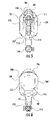
- FIG. 2 shows a side view of an exemplary paintball loader 400 operatively attached to a representative paintball gun 410 illustrated in phantom.
- the paintball gun includes a main body 412 , a compressed gas cylinder 414 , a front handgrip 416 or foregrip, a barrel 418 , and a rear handgrip 419 .
- the paintball gun also includes an infeed tube 420 leading to a firing chamber in the interior of the main body and a trigger 422 .
- the front handgrip projects downwardly from the barrel and provides an area for gripping by an operator of the paintball gun.
- the compressed gas cylinder is typically secured to a rear portion of the paintball gun.
- the compressed gas cylinder normally contains CO2, or NO2, although any compressible gas may be used.
- the paintball loader 400 includes a container body 430 , screen, readout, or display 424 , and may include a circuit board that which includes a microprocessor 426 for controlling the operation of the paintball loader, a motor 428 , and an outfeed tube 432 that connects to the infeed tube 420 of the paintball gun.
- FIG. 3 shows a known paintball marker (gun) having a pressure balanced poppet valve system, as in the MINITM paintball marker, and FIG. 4 shows an exploded of such a paintball marker.
- the paintball gun 900 of FIGS. 3, 4 include a trigger assembly 901 and a firing assembly 903 .
- the trigger assembly 901 is used to actuate the firing of projectiles (e.g., paintballs) under the force of compressed gas from a source of compressed gas.
- the firing assembly 903 is installed within the body 905 and is used to discharge the projectiles.
- the firing assembly 903 includes a housing 906 having a cylindrical channel 907 , a valving system including poppet 908 , and a bolt 913 .
- the poppet 908 is disposed within the housing 906 with a slimmer front part 909 and a wider rear part 910 .
- the poppet 908 divides by the housing 906 into front air chamber 911 and a rear air chamber 912 with different pressure areas.
- a small through hole 923 is provided in the poppet 908 between the front and the rear air chambers.
- the bolt 913 is placed around a bolt guide 914 toward the forward end 915 of the housing 906 .
- a bolt spring 916 is disposed around the front part 917 of the bolt 913 , biasing the bolt 913 to a rearward, open or ready to fire position.
- a solenoid 918 including a moveable plunger 919 are used to control the opening or closing of an air flow channel 920 , thereby leading to a pressure difference between the front air chamber 911 and rear air chamber 912 adjacent the poppet 908 .
- the poppet 908 is shifted rearward, and some of the air flow is fed into a minor air channel to shift the bolt 913 forward under the force of compressed gas, overcoming the bias of the spring 916 .
- the paintball 142 is discharged by the force of compressed gas entering the major air channel through the bolt.
- a coupling or feed neck 924 is provided at the top portion of the body of the paintball gun 900 .
- This feed neck 924 may be provided as a clamp or locking collet of some type, in order to mechanically attach a paintball loader having an outfeed tube to the feed neck 924 .
- paintball loaders or hoppers sit on top of the paintball marker when mounted for play. This positioning provides a target to opposing paintball sport players. This positioning also provides an obstruction to a player's view. It would be advantageous to have a paintball hopper positioned so that it both avoids providing a target for opposing players, but is also out of a player's line of sight.
- paintball loaders or hoppers have been mounted below the breech area of paintball markers
- these “box”-type loaders are bulky, and are positioned in front of the trigger or grip portions of the paintball markers, below the breech area.
- These paintball loaders must feed upwards into the breech area, against gravity.
- a paintball marker must be customized or reconfigured to fit such paintball loaders.
- these paintball loaders sit toward the front of the paintball marker. Accordingly, it would be advantageous to have a paintball loader that is not mounted on top of a paintball marker, where no special reconfiguration is required to attach the paintball loader to the paintball marker.
- paintball markers and paintball loaders or hoppers are separate items that must be mechanically joined by, for example, an adaptor, clamp or collet of some type.
- This adapter provides a stress point, and can come uncoupled during game play. Accordingly, it would be advantageous to have a paintball marker and paintball hopper contained in a single, unitary body.
- paintball markers and paintball hoppers have separate, non-communicating electronics and/or control units. That is, the paintball marker has its own control circuitry or electronics operating independently, and the paintball loader has its own control circuitry or electronics operating independently. It would be advantageous to have a single set of electronics and/or control circuitry and/or control unit that controls, monitors, synchronizes, integrates and/or operates both the paintball marker and the paintball hopper.
- paintball markers and paintball loaders may be difficult to “field strip,” that is, disassemble for cleaning, adjustment or any types of maintenance, particularly during paintball sport play, and without tools. It would be advantageous to have both a paintball marker and an integrated paintball loader that is easy to field strip, without the use of tools.
- a compressed gas gun comprising a body housing both the firing assembly of the gun and an internal projectile feed (“loader”) mechanism.
- the projectile feed mechanism is preferably housed completely internally within the body of the compressed gas gun loader.
- the projectile feed mechanism preferably includes a feed tube having a portion having a generally “S”-shaped cross-section.
- the projectile feed mechanism may be positioned at a horizontal point lower than the firing assembly of the compressed gas gun.
- Another feature of the compressed gas gun having a built-in internal loader of the present invention is tool-less “field stripping,” or removal of certain components completely from the interior of the body of the compressed gas gun, without the need for tools.
- FIG. 1 shows a cross-sectional view of an exemplary compressed gas gun including a firing assembly.
- FIG. 2 shows a side view of an exemplary paintball loader operatively attached to a compressed gas gun.
- FIG. 3 shows a partial cross-sectional view of the internals of another exemplary compressed gas gun and firing assembly.
- FIG. 4 a left side, top, front perspective view of an exemplary a compressed gas gun according to the present invention.
- FIG. 5 shows a front view of an exemplary a compressed gas gun according to the present invention.
- FIG. 6 shows a rear view of an exemplary a compressed gas gun according to the present invention.
- FIG. 7 shows a left side view of an exemplary a compressed gas gun according to the present invention.
- FIG. 8 shows a right side view of an exemplary a compressed gas gun according to the present invention.
- FIG. 9 shows a top view of an exemplary a compressed gas gun according to the present invention.
- FIG. 10 shows a bottom view of an exemplary a compressed gas gun according to the present invention.
- FIG. 11 shows a top view of an exemplary a compressed gas gun according to the present invention with the top rail assembly removed.
- FIG. 12 shows a right side view of an exemplary a compressed gas gun according to the present invention with the right portion of the body shell removed to expose the internals of the compressed gas gun.
- FIG. 13 shows a right side cross sectional view of an exemplary a compressed gas gun according to the present invention.
- FIG. 14 shows a left side view of an exemplary a compressed gas gun according to the present invention with the left portion of the body shell removed to expose the internals of the compressed gas gun.
- FIG. 15 shows a left side cross sectional view of an exemplary a compressed gas gun according to the present invention.
- FIG. 16 shows a left side view of an exemplary top rail assembly, upper wall, firing assembly, feed tube, and projectile feed mechanism of a compressed gas gun according to the present invention.
- FIG. 17 shows a cross-sectional left side view of an exemplary top rail assembly, upper wall, firing assembly, feed tube, and projectile feed mechanism of a compressed gas gun according to the present invention.
- FIG. 18 shows a closer view of an exemplary a cross-sectional left side view of an exemplary portion of a top rail assembly, upper wall, firing assembly, and portion of the feed tube of a compressed gas gun according to the present invention.
- FIG. 19 shows a closer view of a cross-sectional left side view of an exemplary portion of a top rail assembly, feed tube and projectile feed mechanism of a compressed gas gun according to the present invention.
- FIG. 20 shows a top view of an exemplary rear portion of an embodiment of a compressed gas gun according to the present invention, with reservoir extenders.
- FIG. 21 shows an exploded view of an exemplary compressed gas gun according to the present invention.
- FIG. 22 shows an exemplary firing assembly for a compressed gas gun according to the present invention.
- FIG. 23 an exploded view of an exemplary firing assembly for a compressed gas gun according to the present invention.
- FIG. 24 shows an exemplary feed tube or feed ramp of compressed gas gun according to the present invention.
- FIG. 25 shows an exemplary top rail assembly of compressed gas gun according to the present invention.
- FIG. 26 shows removable pins used to hold components of a compressed gas gun according to the present invention in the interior of the compressed gas gun.
- FIG. 27 shows an exploded view of an exemplary projectile feed mechanism of the present invention.
- FIG. 28 shows a portion of an exemplary compressed gas gun according to the present invention with the top rail assembly attached.
- FIG. 29 shows a portion of an exemplary compressed gas gun according to the present invention with the top rail assembly removed exposing the interior of the compressed gas gun body for field stripping.
- FIG. 30 shows a portion of an exemplary compressed gas gun according to the present invention, viewed from the right side and top, with the feed ramp partially removed from the interior of the compressed gas gun body.
- FIG. 31 shows a portion of an exemplary compressed gas gun according to the present invention on its side, with the top rail assembly and breech covers removed, and with the feed ramp partially removed.
- FIG. 32 shows a portion of an exemplary compressed gas gun according to the present invention on its side, with the top rail assembly and breech covers removed, and with the feed ramp completely removed, and exposing the firing assembly in the interior of the compressed gas gun.
- FIG. 33 shows a portion of an exemplary compressed gas gun according to the present invention from the side and top, with the top rail assembly removed, and the firing assembly partially removed from the interior of the compressed gas gun.
- FIG. 34 shows a portion of an exemplary compressed gas gun according to the present invention on its side, with the top rail assembly, breech covers, firing assembly, and pins completely removed from the body of the compressed gas gun.
- FIG. 35 shows the underside of an exemplary firing assembly of an exemplary compressed gas gun according to the present invention, showing the control circuitry.
- FIG. 36 shows the inside of an exemplary compressed gas gun according to the present invention, showing the interior space where the firing assembly may be removably attached.
- FIG. 37 shows a schematic of control circuitry and various sensors and electronics for an exemplary compressed gas gun according to the present invention.
- FIG. 38 shows a diagrammatic representation of the operation of exemplary control circuitry of an exemplary compressed gas gun according to the present invention.
- a compressed gas gun 700 is provided, the exterior of which is shown in FIGS. 4-10 , having an internal, built-in projectile feed mechanism, and preferably includes a gun body 701 having a front portion 704 , rear portion 705 , top (or “upper”) portion 706 , bottom (or “lower”) portion 707 , left side portion 708 and right side portion 709 .
- the gun body 701 includes an exterior 702 and an interior 703 .
- a barrel portion 710 including a barrel 711 , is provided adjacent the front portion 704 .
- Various rails 720 such as “picatinny”-type rails are provided for attaching items (such as flashlights, sights, tools, etc.) to the gun body 701 .
- the gun body 701 includes a grip portion 713 .
- a trigger guard 714 is provided, including a trigger 715 for firing the gun.
- the gun body 701 includes an opening 724 where a user's hand can fit, located between the grip portion 713 and the rear or projectile feed mechanism portion 721 of the gun body.
- the trigger 715 may actuate an electric switch 778 to initiate a firing operation.
- a firing assembly portion 712 is provided above the grip portion 713 .
- the rear portion 705 of the gun body 701 contains the built-in projectile feed mechanism portion 721 and includes an internal projectile feed mechanism 747 , described in greater detail herein.
- the gun body of the present invention comprises a unitary housing with the projectile feed mechanism built into the gun body. This eliminates the need for a separate paintball loader, hopper or magazine.
- the projectile feed mechanism portion 721 effectively comprises a rear or “butt” stock of the compressed gas gun. Included at a top of the paintball loader portion is an opening that is selectively closed/opened by a lid 722 .
- the lid 722 may be hingedly attached to the gun body by a hinge 763 .
- a “quick feed” or “speed feed” type of lid may be employed, including flexible fingers 723 that allow a paintball loader pod to load paintballs into the opening, without opening the lid.
- An exemplary quick-feed lid-type system is shown and described in U.S. Pat. No. 6,234,157, the entire contents of which are incorporated herein by reference as if fully set forth herein.
- the quick-feed lid-type system allows a user to dump or load a container of paintballs into the reservoir of a paintball hopper, by forcing apart the flexible fingers 723 , and thus, there is no need to open the lid to load paintballs.
- the flexible fingers 723 act as a one-way check valve system.
- the compressed gas gun body 701 may further include a battery door 727 that may slide or hingedly open for access to a power source 753 such as batteries, and including a battery holder 768 .
- the power source is connected to a switch to power the electronics of the compressed gas gun ON/OFF.
- a regulator 745 of regulating and/or otherwise adjusting the gas pressure from an attached compressed gas tank may be provided adjacent the grip portion 713 .
- a coupling 769 for attaching a compressed gas tank to the compressed gas gun is provided adjacent the grip portion 713 .
- the coupling 769 is generally threaded and configured to accept the threaded portion of a compressed gas tank, as is well known in the art.
- the coupling may be in the form of a “bottom line” 719 portion as is known in the art.
- the compressed gas gun body may further include one or more breech covers 805 , 806 covering side breech openings 929 allowing access to the interior 930 of the firing assembly portion 712 of the gun body, such as for service.
- the breech covers 805 , 806 are preferably located on opposite sides of the compressed gas gun body 701 , adjacent a breech area 770 .
- a mode selector switch 725 may be provided for selecting between various firing modes (single short, burst, automatic, semi-automatic) in communication with control circuitry of the compressed gas gun.
- the selector switch that 725 is user-actuable and may include one or more firing modes—Semi, Burst, Ramping, Full Auto and Select Fire.
- the firing mode selection electronics may also be in communication with and controlled by the control circuitry.
- An exemplary firing assembly 728 (or “firing mechanism”) that may be used is a pressure balanced poppet valve system similar to those in the MINITM, AXETM, or TMTM compressed gas guns, and examples of which are shown in greater detail in FIGS. 16, 17, 18, 21, 21, 22, and 23 . It is appreciated, however, that any firing assembly for firing projectiles such as paintballs under the force of compressed gas may be used in a built-in, interior paintball loader arrangement of the present invention.
- the firing assembly should be a removable unit containing all, some or most of the components needed to chamber and fire a projectile, such as, for example, the bolt, valving system, and electronics.
- the exemplary compressed gas gun firing assembly 728 illustrated, and shown in greater detail in FIGS. 13, 15, 16, 17, 18, 21, 22 and 23 includes a housing portion 729 generally defining a breech area 770 , with a generally cylindrical interior portion.
- a bolt 730 having a channel (or bolt passage) for communicating gas therethrough is provided in the forward portion of the housing movable from a first or rearward or ready-to-fire or loading position to a second or forward or firing position.
- the bolt 730 is biased by a bolt spring 731 to a rearward position.
- the bolt coaxially surrounds a bolt guide 736 , which is stationary in the housing.
- a channel runs through the bolt guide 736 , providing fluid communication from a rear portion of the housing to the bolt and a forward portion of the housing.
- a velocity adjuster 744 may be provided to the rear of the valve housing 771 , which can be adjustment to control the volume of the valve housing 771 , and this controls the velocity of projectile firing based on compressed gas volume.
- a transfer tube or compressed gas tube 739 is provided, positioned within the body, providing a compressed gas channel 740 for communicating compressed gas from a compressed gas tank, as regulated by the regulator 745 , to the valve housing 771 of the firing assembly 728 .
- Compressed gas from the compressed gas tube 739 flows into a poppet or valve housing 771 of the housing.
- the valve housing 771 may comprise a compressed gas area or chamber 738 for receiving compressed gas from a source of compressed gas such as a gas tank.
- a poppet 732 is positioned in the valve housing 771 of the housing and moveable from a rearward to a forward position.
- the poppet 732 in the forward position, is positioned adjacent a rear opening in the bolt guide, closing a flow path or channel F.
- the poppet 732 includes a gas channel 772 through the body of the poppet 732 , permitting compressed gas in the valve housing 771 to flow through the poppet valve body to the rear of the poppet valve.
- a poppet spring 733 may also be provided to the rear of the poppet 732 , biasing the poppet to the forward or closed position.
- the control unit 716 (or “control circuitry” or “control electronics”) of the compressed gas gun may include a circuit board 717 including control circuitry for controlling operations of the compressed gas gun, and including a controller such as a microprocessor 718 .
- the control unit 716 Upon pulling, depressing, or otherwise actuating the trigger, the control unit 716 sends a signal to a solenoid valve 741 , positioned adjacent the compressed gas tube 739 and in the example gun shown, below the housing 771 .
- the solenoid valve 741 includes a plunger or stopper 742 that regulates a flow of compressed gas through a channel 743 providing communication between a rearward portion of the valve housing 771 behind the poppet, and a rearward facing portion of the bolt.
- the stopper 742 is configured to move from a closed position, where the channel 743 is blocked, to an open position allowing for fluid communication.
- compressed gas from the valve housing 771 is communicated to the bolt 730 through a gas channel.
- the compressed gas acting on the bolt 730 will move the bolt forward (toward a firing position) against the force of the bolt spring 731 toward a firing position, which will act to chamber a paintball that has entered the breech area through the breech opening 761 .
- the imbalance of gas pressure on the poppet 732 since gas is being vented from the space to the rear of the poppet, will cause the poppet to move to the rearward or open position. This will open a flow path or channel F allowing the compressed gas to flow through the bolt guide and bolt to fire a paintball (projectile) from the gun.
- the poppet When the bolt is in the firing position, the poppet is configured to move to the rearward position, at least for the time needed to provide a firing charge of compressed gas, and compressed gas flows from the valve area 771 through the flow path F opened by the poppet 732 , and through the opening in the bolt to fire a projectile through and out the barrel.
- This system will reset when the solenoid valve plunger again closes the gas channel, and the pressure differential will force the poppet to the forward or closed position, as shown in FIGS. 17 and 18 , for example.
- the compressed gas gun according to the present invention further includes a built-in projectile feed mechanism 747 comprising a feeder portion 804 , housed in the projectile feed mechanism portion 721 of the gun body 701 , which may be the rear or butt stock 933 of the gun body 701 .
- the entire projectile feeding mechanism 747 , and a feed ramp 227 (also referred to as feed tube 764 ), is housed essentially completely internally within the body 701 of the compressed gas gun.
- the positioning of the projectile feeding mechanism as in the present invention in the rear portion 705 of the compressed gas gun body 701 allows the paintball loader to act as a butt stock 933 of a generally rifle-shaped compressed gas gun. Since the projectile feeding mechanism is effectively in-line with the rest of the compressed gas gun and/or compressed gas gun body 701 , rather than sitting atop of or below the compressed gas gun body, it reduces the target for paintballs to hit during paintball sport game play.
- the projectile feeding mechanism portion is preferably positioned horizontally lower (along a lower horizontal plane) than the firing assembly, as in butt stocks of rifles. Moreover, the projectile feeding mechanism cannot “fall off” the gun body, as it is internal and fully contained.
- a portion of the interior space or projectile reservoir 762 is provided in the body 701 at the upper part of the projectile feed mechanism portion for receiving and storing projectile (paintballs), as in a conventional paintball loader.
- the reservoir 762 is sized to hold upwards of 50 or more paintballs, and preferably holds over 200 paintballs.
- body extender portions 800 may be provided, which increase the capacity of the reservoir such as up to 250, 300, or more paintballs. This can be provided as “bubble” extender portions 800 that increase the capacity of the reservoir, and could either be on the right or left side of the compressed gas gun body, taking into account whether the user is right or left handed.
- the extenders portions 800 have openings in communication with the reservoir 762 provided in the body 701 , or replace removable sidewalls adjacent the reservoir 762 .
- the projectile feed mechanism 747 is provided at a lower portion of the interior space 703 of the gun body 701 .
- the projectile feed mechanism 747 preferably includes a feeder 748 rotatable about a central axis ‘A’ within a catch cup 756 , with a drive shaft 751 powered by a motor 752 having a power source such as a battery.
- the catch cup 756 includes annular walls for containing paintballs driven by the feeder 748 .
- the feeder 748 preferably includes at least one or a plurality of arms, fins, or extensions 820 forming at least one space or pockets, gaps or spaces 749 for receiving projectiles placed in the interior space, which may fall by gravity into the spaces 749 .
- the feeder 748 has a generally outwardly and downwardly sloping feed surface along its circumference for guiding and/or receiving paintballs into the spaces 749 .
- the feeder 748 may have an overall conical or frusto-conical shape.
- the feeder and feeding mechanism may be designed as in U.S. Pat. No. 6,109,252, the entire contents of which are incorporated by reference as if fully set forth herein.
- a belt drive system may be utilized for rotating the feeder, as described in U.S. Pat. No. 7,343,909, the entire contents of which are incorporated by reference as if fully set forth herein.
- the drive shaft 774 may project downward to engage a drive member 776 that is part of the drive mechanism such as a gear or series of gears driven by a motor 752 .
- the drive member 776 may be a gear having a plurality of spaced apart gear teeth.
- the gear teeth are adapted to engage with mating teeth on a second gear 775 having a drive belt 777 connected to the drive shaft and/or motor 752 .
- the drive member in the illustrated embodiment is a gear, other types of conventional drive members can be used to produce controlled rotation, such as a pulley mechanism or stepper motor.
- the above embodiment of the drive mechanism is an illustrative embodiment only, and that other drive suitable drive mechanisms may be used.
- the drive shaft can be coupled directly to the motor.
- Rotation of the feeder 748 drives projectiles 142 toward the exit opening 755 , which may generally be an opening in a wall of the catch cup 756 .
- the exit opening 755 is at a forward end of the feed mechanism.
- a catch arm or tube extension 746 and/or deflector 754 may be provided for guiding paintballs from the feeder and into the exit opening, and preventing projectile jams or mis-feeds, as described in U.S. Pat. Nos. 6,213,110, 6,502,567, and 6,792,933, the entire contents of all of which are hereby incorporated by reference as if fully set for the herein.
- FIG. 27 also shows, schematically, the electronics and/or control circuitry that may be provided to control operation of the projectile feed mechanism.
- a feed sensor 784 or breech sensor 814 may be in communication with paintball feed mechanism control circuitry 773 (such as electronics or electrical circuitry).
- paintball feed mechanism control circuitry 773 may also be in communication with control unit 716 (alternately described as part of central control unit 1000 ), described in greater detail herein. The communication may be wired or wireless.
- separate paintball control circuitry 773 may be provided in communication with the feed mechanism.
- the projectile loader control circuitry 773 may include a microprocessor in communication with one or more sensors.
- sensors 784 and/or 782 may be directly in communication with control unit 716 (alternately described as part of control unit 1000 ), so that a single control unit controls both the feed assembly 728 and the projectile feed mechanism 747 .
- the central compressed gas gun control unit 716 may also control operation of the projectile feed mechanism 747 as well.
- a single circuit board 717 or control circuitry can also be used to control both the firing assembly 728 and the projectile feed mechanism 747 , and can be powered by a single power source (e.g. battery or batteries), thus eliminating the need for additional circuitry, controllers or batteries.
- the control circuitry 773 and/or the compressed gas gun control unit 716 , or central control unit 1000 may have some or all of the following features.
- a contact, sound, pressure or shock sensor, or detector 780 may be provided configured to detect a signal based on a compressed gas gun firing event, or sound, or other pressure waves in a medium, and operate the motor in response thereto, such as in U.S. Pat. Nos. 5,947,100 and 5,791,325, the entire contents of all of which are hereby incorporated by reference as if fully set forth the herein.
- the detector 780 will detect or sense a firing event (e.g., sound, pressure waves in a medium, shock waves, a trigger pull, bolt movement, hammer movement, an electronic signal indicative of a compressed gas gun being fired, projectile movement), and send a signal indicative of such a firing event to control units, control circuitry and/or electronics of the compressed gas gun and/or the projectile feed mechanism.
- a firing event e.g., sound, pressure waves in a medium, shock waves, a trigger pull, bolt movement, hammer movement, an electronic signal indicative of a compressed gas gun being fired, projectile movement
- the control units, control circuitry and/or electronics will process and determine the proper action and/or adjustment in response to such a signal, such as operating and/or otherwise controlling the motor (starting, stopping, speeding up, reversing, or slowing down) of the projectile feed mechanism, updating information regarding the firing parameters (e.g., rate of fire, valve dwell time, velocity, gas expended, shot count, ramping) of the compressed gas gun, regulating the firing parameters of the compressed gas gun, or similar adjustments or actions, or any combination thereof.
- the firing parameters e.g., rate of fire, valve dwell time, velocity, gas expended, shot count, ramping
- one or more break-beam, optical, or infra-red sensors 782 may be provided to detect paintballs or the movement of paintballs at a selected position in the feed mechanism, such as in the feed tube, and control the motor of the feed mechanism in response to such detection, as in U.S. Pat. No. 5,816,232; 6,213,110; 6,502,567; or 6,792,933, the entire contents of all of which are hereby incorporated by reference as if fully set forth herein.
- the sensor 782 will detect or sense a projectile or projectile movement, and send a signal indicative of such projectile or projectile movement to control units, control circuitry and/or electronics of the compressed gas gun and/or the projectile feed mechanism.
- the control units, control circuitry and/or electronics will process and determine the proper action and/or adjustment in response to such a signal, such as operating and/or otherwise controlling the motor (starting, stopping, speeding up, reversing, or slowing down) of the projectile feed mechanism, updating information regarding the firing parameters (e.g., rate of fire, valve dwell time, velocity, gas expended, shot count, ramping) of the compressed gas gun, regulating the firing parameters of the compressed gas gun, or similar adjustments or actions, or any combination thereof.
- the firing parameters e.g., rate of fire, valve dwell time, velocity, gas expended, shot count, ramping
- one or more breech sensors 814 may be provided for sensing projectiles within the breech area 770 .
- the sensor 783 will detect or sense a projectile or projectile movement, and send a signal indicative of such projectile or projectile movement to control units, control circuitry and/or electronics of the compressed gas gun and/or the projectile feed mechanism.
- the control units, control circuitry and/or electronics will process and determine the proper action and/or adjustment in response to such a signal, such as operating and/or otherwise controlling the motor (starting, stopping, speeding up, reversing, or slowing down) of the projectile feed mechanism, updating information regarding the firing parameters (e.g., rate of fire, valve dwell time, velocity, gas expended, shot count, ramping) of the compressed gas gun, regulating the firing parameters of the compressed gas gun, or similar adjustments or actions, or any combination thereof.
- the firing parameters e.g., rate of fire, valve dwell time, velocity, gas expended, shot count, ramping
- a feeder sensor 784 may be provided for detecting movement of the feeder such that the motor may be operated or controlled in response thereto, as in U.S. Pat. No. 6,889,680, the entire contents of which are hereby incorporated by reference as if fully set forth herein.
- the sensor 784 will detect or sense the movement, speed, and/or lack of movement or speed of the feeder, and send a signal indicative of such to control units, control circuitry and/or electronics of the compressed gas gun and/or the projectile feed mechanism.
- the control units, control circuitry and/or electronics will process and determine the proper action and/or adjustment in response to such a signal, such as operating and/or otherwise controlling the motor (starting, stopping, speeding up, reversing, or slowing down) of the projectile feed mechanism, updating information regarding the firing parameters (e.g., rate of fire, valve dwell time, velocity, gas expended, shot count, ramping) of the compressed gas gun, regulating the firing parameters of the compressed gas gun, or similar adjustments or actions, or any combination thereof.
- the firing parameters e.g., rate of fire, valve dwell time, velocity, gas expended, shot count, ramping
- a sensor or sensors in communication with one or more transmitters 786 and receivers 788 may be provided for detecting a firing event and operating the motor in response thereto, as in U.S. Pat. No. 8,448,631, the entire contents of which are hereby incorporated by reference as if fully set forth herein.
- the sensor will detect a firing event and a signal will be transmitted via a transmitter to a receiver in communication with the control circuitry indicative of such signal and firing event.
- the control units, control circuitry and/or electronics will process and determine the proper action and/or adjustment in response to such a signal, such as operating and/or otherwise controlling the motor (starting, stopping, speeding up, reversing, or slowing down) of the projectile feed mechanism, updating information regarding the firing parameters (e.g., rate of fire, valve dwell time, velocity, gas expended, shot count, ramping) of the compressed gas gun, regulating the firing parameters of the compressed gas gun, or similar adjustments or actions, or any combination thereof.
- the firing parameters e.g., rate of fire, valve dwell time, velocity, gas expended, shot count, ramping
- sensors or detectors described herein may be electrically wired, or operate in a wireless fashion with transmitters and receivers. Any combination of sensors or detectors may be used to control, regulate and/or adjust the operation of the compressed gas gun of the prevent invention. Other means for operating the motor of the feed mechanism may also be provided without departing from the teachings of the present invention.
- a feed tube 764 (also referred to herein as a “feed ramp” 227 ) having several identifiable portions is provided, although it is noted that the feed tube 764 may be one piece or several pieces.
- a first portion 757 of the feed tube is in communication with the exit opening 755 of the catch cup.
- the first portion 757 is curved, and preferably curves forwardly and upwardly as shown in FIGS. 17 and 19 .
- the first portion 757 is in communication with a second portion 758 .
- the second portion 758 is also curved, curving upwardly and away from the first portion to form a generally “S”-shaped transition portion 765 (which also can be described as having a “wave” shape) of the feed tube 764 .
- the “S”-shaped transition portion 765 is preferable, as the paintballs in a paintball stack forced by the feeder 748 through the feed tube 764 preferably undergo a smooth transition from the paintball feeder and initially upward and toward the breech, through the feed tube 764 .
- This “S”-shaped transition portion 765 of the feed tube assists in preventing paintballs from rupturing or jamming in the feed tube.
- a third portion 759 which is generally horizontal, of the feed tube extends from the second portion 758 forward along the compressed gas gun body interior 703 , as shown in FIGS. 12-18 . As shown, the third portion 759 of the feed tube 764 extends along an upper wall 766 of the interior 703 of the compressed gas gun body.
- the third portion 759 may be generally horizontal or flat along the majority of its length, or may have a curve in it.
- the feed tube 764 comprises, in part, an upper wall 766 formed by an inner surface 767 of the top portion 706 of the compressed gas gun body 701 , which may be formed as a removable top rail assembly 249 .
- the inner surface 767 of the upper wall 766 completes the tubular shape of the feed tube 764 along its upper portion.
- the upper wall 766 is removable as a top rail assembly 249 , exposing an open portion 760 of the gun body interior 703 including a portion of the feed tube 764 for cleaning, maintenance or otherwise gaining access to the interior of the compressed gas gun. Portions of the feeder portion 804 may also be accessible when the upper wall 766 is removed.
- the upper wall 766 is formed as part of a top rail assembly 249 , having at an upper surface various rails such as “picatinny” rails, and at a lower surface the upper wall 766 of the feed tube 764 including the inner surface 767 .
- This top rail assembly 249 forms a top wall at the upper portion 706 of the compressed gas gun body 701 , and can be removed as described herein to provide easy access to the interior 703 of the gun body 701 .
- the top rail assembly 249 of the compressed gas gun body 701 may be attached and removable by a tongue-in-groove arrangement, by a button release assembly 252 , by a pin or pins 781 inserted through holes 125 in the top rail assembly 249 and/or body 701 and/or upper wall 766 , it may rotate about a hinge attached at one end to the compressed gas gun body, or may be attached in another manner such as snapping in place, or a combination of any of the foregoing.
- the top rail assembly 249 of the compressed gas gun body 701 including the upper wall 766 , may be attached by magnets to the compressed gas gun body, or by a friction fit.
- the front end 934 of the third portion 759 of the feed tube 764 curves downwardly at its forward end toward the breech opening 761 of the breech area 770 , where a paintball is delivered to the firing assembly 728 for firing by the firing assembly 728 under the force of compressed gas, through the barrel 711 .
- the feed tube 764 delivers projectiles to the breech area 770 from above the breech area 770 .
- the arrangement of the present invention permits a complete built-in, internal projectile feed mechanism and loader, housed within the body of a compressed gas gun, yet still allows for projectile loading from above the breech area. This above-breech loading is preferable, as the paintballs do not have to work against the force of gravity when loading into the breech.
- the projectile feed mechanism 747 is preferably positioned lower (horizontally when the gun is held in a firing position) than the firing assembly 728 .
- This arrangement corresponds to the overall shape of the compressed gas gun, whereby the butt stock is generally ergonomically positioned lower than the breech.
- the internal paintball loader of the present invention cannot fall off or otherwise be disconnected during use, and cannot get in the way of or otherwise obstruct a paintball sport player.
- the compressed gas gun may have the projectile feed mechanism 747 positioned in the stock in a “bullpup” type of design, as is known in the art of firearms.
- the design of the gun of the present invention allows a player in the sport of paintball, for example, to reduce their silhouette and never take a “hit” on an exposed projectile loader.
- the projectile feed mechanism 747 may include a microprocessor 718 to enhance the performance of the projectile feed mechanism 747 as well as providing useful information to an operator.
- the microprocessor 718 may control the motor 752 to rotate it in a first direction for feeding, and in a second or reverse direction to clear a jam.
- a compressed gas gun preferably includes a body 701 or “shell” having a left side portion 708 , and a right side portion 709 .
- the two sides 708 , 709 are connected (such as by screws or bolts, etc.) to form the complete body 701 that will house the various components, and in particular, will house both the firing assembly 728 and the feeder portion 804 .
- a compressed gas gun 700 preferably comprises one or more of the following components: a removable top rail assembly 249 that forms the upper wall of the body; a “feed ramp” 227 or “feed tube” 764 that acts as a ramp or raceway for conveying projectiles 142 from the feeder portion 804 or the projectile feed mechanism 747 to the firing assembly 728 ; a left side breech cover 805 ; a right side breech cover 806 ; a battery holder 768 including batteries 807 ; a lid 722 for covering the opening 818 in the body 701 adjacent the projectile feed mechanism portion 721 ; a compressed gas regulator 809 for controlling the operation pressure of compressed gas supplied to the compressed gas gun from a compressed gas supply (e.g., air or gas tank); a barrel 711 ; a compressed gas adaptor 810 for attachment to a source of compressed gas such as an air or gas tank; removable pins 781 (removable without the need for tools) for attaching
- a compressed gas supply e.g., air
- the firing assembly 728 preferably comprises one or more of the following components: a bolt assembly 730 for chambering and firing a projectile (e.g., a paintball); a solenoid valve assembly 741 that may be initiated by a trigger 715 pull, for regulating the flow of compressed gas to the bolt 730 in order to perform a firing operation; detents 811 for assisting in holding and/or positioning a projectile in place in the breech for firing; a manifold 812 including gas passages for the flow of compressed gas; control unit 716 including a circuit board 717 and preferably including a microprocessor 718 , for controlling both the firing operation of the firing assembly 728 , and the loading operation of the projectile loader of the compressed gas gun; sensor harnesses 813 including breech sensors 814 , for detecting whether a projectile is properly loaded into the breech; an air
- FIGS. 17 and 27 show the components of a projectile feed mechanism (or paintball loader) according to the invention.
- a projectile feed mechanism according to the present invention preferably comprises one or more of the following components: a catch cup 756 , for holding a feeder 748 and receiving or “catching” projectiles for feeding; a “catch arm” or tube extension 746 for catching and/or guiding projectiles into the exit opening 755 ; an anti-jam 302 such as a deflector 754 , for assisting in preventing projectile jams at the exit opening 755 of the catch cup 756 ; a drive shaft 751 in communication with drive gears 775 , 776 and a motor 752 and a feeder 748 , configured for rotation by the motor 752 ; a feeder 748 (or carrier) for feeding projectiles that is attached to the drive shaft and rotated with the drive shaft by the drive gears and motor; a motor 752 , in communication with drive mechanism 775 , 776 ; feed sensor 784 for
- FIGS. 17-19, 2, 24 and 32 show a feed ramp 227 (also described herein with reference to feed tube 764 ), including a feed ramp back 229 , a feed ramp extension 231 , and a feed ramp top 233 .
- the feed ramp 227 is in communication with and releasably joins the upwardly turned exit ramp 309 (also described as first portion 757 ) adjacent the exit opening 755 of the projectile feed mechanism 747 .
- feed ramp back 229 is releasably attached, such as by flanges and grooves shown in FIG. 24 and such as by a snap fit, to feed ramp extension 231 .
- feed ramp top 233 may be attached to feed ramp back 229 by a spring pin, such that feed ramp top can operate as a flip top that is spring-biased.
- FIGS. 21, 25, 31, 32 and 34 show the top rail assembly 249 of the body of the compressed gas gun.
- the top rail assembly 249 is releasably attached to the body 701 by spring-biased detent or button release assembly 252 which extends through holes 253 in the body 701 of the upper portion of the compressed has gun 700 . Pressing the button releases of the button release assembly 252 toward each other against the bias of the spring allows movement of the top rail assembly 249 relative to the upper portion of the body. This provides a “quick release” function for removing the top rail assembly 249 .
- the top rail assembly 249 that is preferably completely removable, although a partially removable version is also contemplated.
- the top rail assembly 249 may slide into place along the top of the top portion 706 of the body 701 of the gun 700 , such as by a tongue and groove or flange and groove arrangement.
- the buttons 252 will be biased by the spring into the holes 253 in the upper portion of the body provided for receiving the buttons.
- the top rail assembly 249 may be slidable from a first locked (e.g., the buttons are snapped or locked into the holes in the body) position, to a second unlocked position for removal.
- FIGS. 12-15 and 28 show the top rail assembly 249 in the locked position, with the buttons 252 extending through the holes 253 in the body 701 .
- the inner surface 767 of the top rail assembly 249 may comprise the top of a feed ramp 227 (or as also described, feed tube 764 ) for transferring projectiles from the projectile feed mechanism of the compressed gas gun to the elements of the firing assembly 728 (e.g., the breech or bolt).
- the inner surface 767 is preferably at least partially curved or semi-circular in cross-section forming the upper half of a tube, with the feed ramp extension 231 forming the other part of the tube.
- One or more pins 781 may preferably be used to hold the feed ramp 227 in place.
- the pins 781 preferably extend through openings 125 in the body and openings in the feed ramp 125 , as shown in FIGS. 30-32 .
- the pins 781 shown in detail in FIG. 26 , are formed so as to be removable by a person without the need for tools, and have spring biased attachment means for locking in place.
- the pins 781 may be friction fit with a flange or spring clip to lock in place.
- the feed ramp 227 may be held in place such as by a snap fit, or a tongue-in-groove fit.
- the feed ramp extension 231 and feed ramp back 229 may snap together with a flange and grooves as shown in FIGS. 17, 19, 21, 2 and 32 , to releasable engage the upwardly turning exit ramp (or “exit tube”) 309 (also described as the first portion 757 of the feed tube 764 ) of the projectile feed mechanism 747 .
- FIGS. 30-32 show the feed ramp 227 completely removed from the body 701 .
- FIGS. 30-32 show the left side breech cover 805 and right side breech cover 806 , which are removably attachable to sides of the body adjacent the breech, and which hold the detents 811 in place. Removal of the left side breech cover 805 and right side breech cover 806 provides additional access to the inner portions and interior 703 of the body, adjacent the breech area 770 .
- FIGS. 35-36 Removal of the feed ramp 227 through the opening in the top of the gun exposes the firing assembly 728 of the compressed gas gun, as shown in FIG. 32 .
- the firing assembly 728 may be held in place by hand or finger-removable attachment portions 504 that may include attachment slots 501 , and attachment portions 504 in the interior 703 of the gun body that may include attachment pins 502 , or snap fit into place. Once disengaged from any fittings, the firing assembly 728 can be lifted out of the body 701 as a single unit, as shown in FIGS. 33-34 . Removal of the firing assembly 728 of allows for service, maintenance, adjustment, cleaning, etc. FIGS.
- the attachment portions 503 , 504 which may attach by a friction fit and lock into place, and may be electrical junctions, that may further provide electrical connections for the control circuitry of the firing assembly and the power source (e.g., battery or batteries) of the gun.
- the power source e.g., battery or batteries
- a unique feature of a compressed gas gun according to the invention is the use of one control circuit for controlling operation of the both the firing assembly (solenoid, or compressed gas gun electronics), as well as the operation of the paintball loader (motor, or projectile feed mechanism electronics).
- the control circuitry of the compressed gas gun may be configured to control, operate, adjust, regulate and/or coordinate the compressed gas gun electronics and the loader electronics such that a more efficient, comprehensive compressed gas gun, which according to the invention includes an integral projectile feed mechanism, is provided.
- the control circuitry preferably includes a microprocessor and software for operation of the gun and monitoring, regulating, sensing, controlling, or otherwise accessing gun operations or parameters.
- FIG. 37 shows a schematic representation of the central control unit 1000 (or “central control circuitry” or “central control electronics”, and which may include or comprise control unit 716 ), which may comprise a circuit board, electronics necessary for controlling operation of the compressed gas gun and projectile firing mechanism, and which may include a microprocessor and software for controlling and/or otherwise operating the compressed gas gun and projectile firing mechanism. As shown in FIG.
- the central control unit 1000 is preferably in communication with a breech sensor or plurality of breech sensors 1002 (which may be sensors 814 ); a projectile feed mechanism sensor or plurality of projectile feed mechanism sensors 1003 (which may be sensors 782 and/or 784 ); a trigger switch 1004 actuated by pulling a trigger; the projectile feed mechanism motor and/or other projectile feed mechanism components and/or electronics 1005 ; the solenoid and/or firing assembly components and/or electronics 1006 ; and a user interface 1007 .
- the user interface 1007 includes user-actuable switches, buttons, pads, or a joystick, whereby a user can input selections to the software of the control circuitry, and may include a display screen 1008 .
- the mode selector electronics 1009 which may include a mode selector switch 1010 , and also in communication with and controlled by the central control unit 1000 .
- the central control unit 1000 which preferably includes a microprocessor and software, is preferably in communication with one or more sensors 1002 in the breech of the compressed gas gun, and one or more sensors 1003 in the projectile feed mechanism.
- the control unit 1000 is further in communication with a trigger switch 1004 .
- the control unit 1000 can receive and process signals received from the trigger switch 1004 , breech sensor 1002 and/or the projectile feed mechanism sensors 1003 . Because the projectile feed mechanism 747 and firing assembly 728 are controlled by the same central control unit 1000 , the control circuitry can operate the functions of the compressed gas gun in a coordinated manner not previously available, taking into account multiple signals and feedback as provided by the various sensors 1002 , 1003 .
- control unit 1000 Examples of operation of the control unit 1000 are described.
- a firing signal may be sent by the trigger switch 1004 to the control unit 1000 .
- the control unit 1000 is configured to process the firing signal and operate or otherwise control the firing assembly 728 and the projectile feed mechanism 747 .
- the control unit 1000 can transmit a firing assembly signal to a solenoid valve 731 that is part of the firing assembly 728 .
- the solenoid valve 731 acts to operate the bolt 730 to chamber and fire a projectile.
- control unit 1000 can also be configured to transmit a feed mechanism signal to the electronics and/or motor of the projectile feed mechanism.
- the feed mechanism signal will cause the projectile feeder of the feed mechanism signal to rotate to feed projectiles along the feed ramp 227 , and into the breech of the firing assembly 728 for firing.
- FIG. 38 shows a flow chart diagramming a potential, illustrative operation of the central control unit 1000 .
- a firing signal is sent to the control circuitry ( 2000 ).
- the control circuitry communicates with the breech sensor to determine whether the breech sensor detects that a projectile is properly loaded into the breech and ready for firing ( 2001 ). If a projectile is not detected in the breech by the breech sensor, or if a projectile is not fully in position in the breech whereby it could be “chopped,” a “no projectile” signal may be transmitted to the control circuitry ( 2002 ).
- No paintballs in the breech, or a paintball improperly positioned in the breech, may be indicative of a paintball jam, that is, a misfed paintball.
- the control circuitry also controls the paintball loader, the “no projectile” signal may be received by the control circuitry, and a “jam clear” signal may be sent to the paintball loader ( 2003 ). This may cause the motor of the paintball loader to either operate in reverse, or in a reverse and forward manner, in an attempt to clear the jammed paintball ( 2004 ). Normal operations may resume once projectiles are detected, for example in the proper position, by the breech sensor ( 2005 ).
- control circuitry may send a simultaneous, or otherwise timed, signal to the solenoid to operate and for the motor of the projectile feed mechanism motor to operate, thereby firing the gun and also simultaneously feeding projectiles ( 2006 ).
- a central control circuit housed in the same body as the firing assembly and the projectile feed mechanism, can gather operational parameters of the gun, which comprises both the firing assembly and the projectile feed mechanism, send operational signals to the firing assembly and the projectile loader, and coordinate and control operation of the firing assembly and the projectile feed mechanism to provide for an efficient, coordinated and improved operation.
- a single electronics platform is provided for both the firing assembly and the projectile feed mechanism.
- the control unit 1000 may be configured to provide for controlled feeding of projectiles, where the speed of the feed rate of the projectile feed mechanism is regulated based upon how quickly or slowly projectiles are being fired. Thus, the speed of the motor of the projectile feed mechanism can be sped up or slowed down to coordinate with the rate of fire.
- a single unit of control circuitry for both the firing assembly and the projectile feed mechanism a single battery or battery pack can be used to power the compressed gas gun according to the present invention.
- a single power source may power the control circuitry, the solenoid of the firing assembly, and the motor of the projectile feed mechanism.
- An additional feature of the control circuitry may be the ability to clear the feed ramp when the gun is powered “off,” such as by an ON/OFF power switch in communication with the power source (batteries).
- the control circuitry sends a “power off” signal to the motor of the projectile loader.
- the motor operates the feeder in reverse, to clear the projectiles in the feed ramp and adjacent the breech.
- a user will remove the loader to make sure there is no balls in the breech or feedneck. With the projectile loader integrated into the gun, reversing the motor of the loader assists in removing projectiles from a feeding or firing position.
Abstract
Description
Claims (10)
Priority Applications (2)
| Application Number | Priority Date | Filing Date | Title |
|---|---|---|---|
| US14/309,958 US9658027B2 (en) | 2013-06-21 | 2014-06-20 | Compressed gas gun having built-in, internal projectile feed mechanism |
| US15/599,970 US20180066913A1 (en) | 2013-06-21 | 2017-05-19 | Compressed gas gun having built-in, internal projectile feed mechanism |
Applications Claiming Priority (3)
| Application Number | Priority Date | Filing Date | Title |
|---|---|---|---|
| US201361837984P | 2013-06-21 | 2013-06-21 | |
| US201361891781P | 2013-10-16 | 2013-10-16 | |
| US14/309,958 US9658027B2 (en) | 2013-06-21 | 2014-06-20 | Compressed gas gun having built-in, internal projectile feed mechanism |
Related Child Applications (1)
| Application Number | Title | Priority Date | Filing Date |
|---|---|---|---|
| US15/599,970 Continuation US20180066913A1 (en) | 2013-06-21 | 2017-05-19 | Compressed gas gun having built-in, internal projectile feed mechanism |
Publications (2)
| Publication Number | Publication Date |
|---|---|
| US20140373823A1 US20140373823A1 (en) | 2014-12-25 |
| US9658027B2 true US9658027B2 (en) | 2017-05-23 |
Family
ID=52105525
Family Applications (2)
| Application Number | Title | Priority Date | Filing Date |
|---|---|---|---|
| US14/309,958 Active US9658027B2 (en) | 2013-06-21 | 2014-06-20 | Compressed gas gun having built-in, internal projectile feed mechanism |
| US15/599,970 Abandoned US20180066913A1 (en) | 2013-06-21 | 2017-05-19 | Compressed gas gun having built-in, internal projectile feed mechanism |
Family Applications After (1)
| Application Number | Title | Priority Date | Filing Date |
|---|---|---|---|
| US15/599,970 Abandoned US20180066913A1 (en) | 2013-06-21 | 2017-05-19 | Compressed gas gun having built-in, internal projectile feed mechanism |
Country Status (7)
| Country | Link |
|---|---|
| US (2) | US9658027B2 (en) |
| EP (1) | EP3011254B1 (en) |
| CN (1) | CN105849500A (en) |
| CA (1) | CA2916428C (en) |
| ES (1) | ES2721255T3 (en) |
| TW (1) | TWI611159B (en) |
| WO (1) | WO2014205313A2 (en) |
Cited By (10)
| Publication number | Priority date | Publication date | Assignee | Title |
|---|---|---|---|---|
| US20170045328A1 (en) * | 2014-11-24 | 2017-02-16 | William S. Nachefski | Efficient high-velocity compressed gas-powered gun |
| US20180066913A1 (en) * | 2013-06-21 | 2018-03-08 | Gi Sportz Direct Llc | Compressed gas gun having built-in, internal projectile feed mechanism |
| US20190195592A1 (en) * | 2017-12-21 | 2019-06-27 | Easebon Services Limited | Easy loading toy projectile launcher |
| US10871343B2 (en) * | 2017-12-21 | 2020-12-22 | Easebon Services Limited | Easy loading toy projectile launcher |
| US20220128329A1 (en) * | 2020-08-26 | 2022-04-28 | Kyle Buckmaster | Apparatus and Methods for Paintball Feeding Mechanism |
| US11340037B1 (en) | 2017-12-21 | 2022-05-24 | Easebon Services Limited | Easy loading toy projectile launcher |
| US11371798B1 (en) * | 2021-10-16 | 2022-06-28 | James Eugene Allen | Air gun |
| US11512925B1 (en) * | 2022-03-03 | 2022-11-29 | Hk Army Inc. | Feeder cover for paintball loader |
| USD992671S1 (en) | 2020-10-08 | 2023-07-18 | Canadian Imperial Bank Of Commerce, As Agent | Projectile launcher and loader |
| US11913750B1 (en) * | 2023-05-31 | 2024-02-27 | Arren Cudal | Airsoft adapter assembly |
Families Citing this family (12)
| Publication number | Priority date | Publication date | Assignee | Title |
|---|---|---|---|---|
| USD745102S1 (en) * | 2014-04-14 | 2015-12-08 | Nicholas E. Young | Firearm |
| USD750722S1 (en) * | 2014-04-14 | 2016-03-01 | Nicholas E. Young | Firearm |
| CN108432150A (en) * | 2015-12-21 | 2018-08-21 | 华为技术有限公司 | The acquisition methods and system, base station equipment of RRU channel frequence response differences |
| EP3187814B1 (en) * | 2015-12-28 | 2018-02-21 | Liang-Chi Shen | Pneumatic firing device |
| US10907935B2 (en) | 2017-06-20 | 2021-02-02 | Cubic Corporation | Indirect fire mission training system |
| US10107595B1 (en) * | 2017-06-20 | 2018-10-23 | Cubic Corporation | Indirect fire mission training system |
| US10634442B2 (en) * | 2018-01-17 | 2020-04-28 | Cubic Corporation | Light gun breech position detector |
| USD874581S1 (en) * | 2018-07-16 | 2020-02-04 | Shenzhen Chuangliansizhong Technology Co., Ltd. | Toy gun component |
| JP7419573B2 (en) | 2020-04-07 | 2024-01-22 | マッジョーレ,ローレン | insecticide gun |
| US11378351B2 (en) * | 2020-09-16 | 2022-07-05 | Guay Guay Trading Co., Ltd. | Cutting-power-off detection structure of toy gun |
| US11203047B1 (en) * | 2020-10-20 | 2021-12-21 | Diversitech Corporation | Projectile launcher |
| US20230408220A1 (en) * | 2021-07-09 | 2023-12-21 | Gel Blaster, Inc. | Toy projectile shooter firing mode assembly and system |
Citations (283)
| Publication number | Priority date | Publication date | Assignee | Title |
|---|---|---|---|---|
| US1332993A (en) | 1918-08-09 | 1920-03-09 | Aero Tank Machine Gun Co Inc | Feeding bullets and the like from hoppers |
| US1332992A (en) | 1918-06-20 | 1920-03-09 | Aero Tank Machine Gun Co Inc | Centrifugal machine-gun |
| US1403689A (en) | 1919-01-09 | 1922-01-17 | Alexander H Hyndman | Magneto |
| US1403719A (en) | 1921-03-05 | 1922-01-17 | Keystone Die And Mfg Company | Toy gun |
| US1404689A (en) | 1922-01-24 | Air gun | ||
| US1743576A (en) | 1927-07-14 | 1930-01-14 | Smith Robert Bigham | Pneumatically-actuated machine gun |
| US1867513A (en) | 1930-07-05 | 1932-07-12 | Lahti Aimo Johannes | Cartridge case |
| US1954093A (en) | 1931-09-11 | 1934-04-10 | Mark W Nelson | Flexible shaft paint mixing apparatus or device |
| US2064888A (en) | 1935-06-04 | 1936-12-22 | Fred A Dickinson | Spiral groove rifle magazine |
| GB470201A (en) | 1936-05-06 | 1937-08-11 | Amerigo Mollica Landi | Machine for throwing projectiles by centrifugal force |
| US2307015A (en) | 1939-04-10 | 1943-01-05 | Boynton Alexander | Pneumatic gun |
| GB551077A (en) | 1942-02-18 | 1943-02-05 | Kildare Scott Martin Croucher | Improvements in fuel feeding devices for furnaces |
| US2338984A (en) | 1941-03-03 | 1944-01-11 | Automatic Appliance Corp | Magazine for firearms |
| US2357951A (en) | 1941-08-19 | 1944-09-12 | Saint Cyr Corp | Pneumatic gun |
| US2398263A (en) | 1941-03-20 | 1946-04-09 | Curtiss Wright Corp | Multiple ammunition boxes |
| FR921527A (en) | 1945-11-22 | 1947-05-09 | New device for projecting, by compressed air, small projectiles, such as shot pellets or the like | |
| US2451521A (en) | 1945-01-09 | 1948-10-19 | Alfred H Uglum | Magazine loader |
| US2526969A (en) | 1945-07-27 | 1950-10-24 | Warren H Powers | Washing machine |
| US2568432A (en) | 1949-08-25 | 1951-09-18 | Ivan R Cook | Electric air gun |
| DE876370C (en) | 1951-01-30 | 1953-05-11 | Fritz Walther | Magazine device for air guns |
| US2639904A (en) | 1949-12-13 | 1953-05-26 | G M Lab Inc | Mixer |
| US2641412A (en) | 1951-05-23 | 1953-06-09 | Jonas J Byberg | Feed mixer and grinder |
| US2676633A (en) | 1950-07-05 | 1954-04-27 | Extraction Inc | Abrading apparatus for removal of fruit surfaces |
| USRE23951E (en) | 1955-02-22 | graham | ||
| US2716973A (en) | 1952-09-04 | 1955-09-06 | Desi Paul Francis | Ball throwing machine |
| US2900972A (en) | 1956-09-24 | 1959-08-25 | De Loss L Marsh | Underwater spear gun |
| US3089476A (en) | 1960-11-07 | 1963-05-14 | Midway Mfg Co | Projectile apparatuses |
| US3134301A (en) | 1959-12-11 | 1964-05-26 | Even Georges Francois Marie | Gun loading apparatus |
| US3248008A (en) | 1964-09-03 | 1966-04-26 | Meierjohan Ernest | Golf ball dispenser or the like |
| US3273553A (en) | 1963-09-12 | 1966-09-20 | Richard H Doyle | Electromagnetically operated gun |
| US3384354A (en) | 1966-07-05 | 1968-05-21 | Gattys Tech | Agitator device |
| US3410453A (en) | 1966-03-15 | 1968-11-12 | Joseph Robert Christopher Lawrence | Ball and like feeding |
| US3467073A (en) | 1966-03-28 | 1969-09-16 | Barry V Rhodes | Automatic ball throwing machine |
| US3610223A (en) | 1970-03-02 | 1971-10-05 | Wallace V Green | Automatically operated spring-type projectile projecting device |
| US3630118A (en) | 1969-09-05 | 1971-12-28 | Stoner Eugene | Two-step ammunition feeder |
| DE2035097A1 (en) | 1970-07-15 | 1972-01-27 | Wegmann & Co, 3500 Kassel | Cartridge feeder for automatic firearms |
| US3695246A (en) | 1971-06-10 | 1972-10-03 | Us Navy | Pneumatic machine gun with photo cell interrupted circuit |
| US3724437A (en) | 1970-11-23 | 1973-04-03 | Tru Pitch Inc | Ball throwing machine |
| US3745687A (en) | 1971-04-07 | 1973-07-17 | Firearm Dev Inc | Rotary magazine for bolt action rifle |
| US3766901A (en) | 1972-01-31 | 1973-10-23 | Tenni Pro Corp | Opposed disc type ball projecting device |
| US3777732A (en) | 1972-03-20 | 1973-12-11 | Metaltek Inc | Device having coacting wheels for projecting tennis balls |
| US3788298A (en) | 1972-06-19 | 1974-01-29 | Victor Comptometer Corp | Compressed gas gun with trigger operated hammer release latching structure |
| US3789891A (en) | 1972-03-02 | 1974-02-05 | J Bosch | B-b gun funnel device |
| US3807379A (en) | 1972-04-07 | 1974-04-30 | H Vodinh | Spring type ball projecting device with programming control means |
| US3814283A (en) | 1972-07-21 | 1974-06-04 | Braden V | Ball collecting and feeding device |
| US3844267A (en) | 1973-05-07 | 1974-10-29 | J Mohr | Tennis ball pitching apparatus with anti-jamming ball feed mechanism |
| US3855988A (en) | 1973-04-13 | 1974-12-24 | Prince Mfg Inc | Ball throwing machine |
| US3867921A (en) | 1972-11-13 | 1975-02-25 | Eugene Jim Politzer | Spring type ball throwing device |
| US3894657A (en) | 1973-09-04 | 1975-07-15 | Roland L Eckmayr | Ball dispensing device |
| US3930486A (en) | 1972-09-28 | 1976-01-06 | Kahelin Edward W | Convertible baseball and tennis practice machine |
| US3978841A (en) | 1975-04-03 | 1976-09-07 | Yarur Alfredo S | Feeding apparatus for ball projecting machine |
| US3990426A (en) | 1975-07-22 | 1976-11-09 | Gilbert Stokes | Tennis ball throwing machine |
| US4021036A (en) | 1975-12-05 | 1977-05-03 | Nelson David M | Tennis teaching machine with ball projector |
| US4027646A (en) | 1976-06-08 | 1977-06-07 | Prince Manufacturing, Inc. | Propulsion device for tennis balls and like spherical objects |
| US4034644A (en) | 1974-06-10 | 1977-07-12 | Industriewerke Karlsruhe-Augsburg Aktiengesellschaft | Firearm and magazine construction |
| US4044290A (en) | 1974-06-21 | 1977-08-23 | Typographic Innovations Inc. | Drum control system |
| US4073280A (en) | 1968-05-21 | 1978-02-14 | Koehn Wilbur R | Rapid fire gun |
| US4112911A (en) | 1977-03-29 | 1978-09-12 | Shooting Star Tennis | Ball collector and projector apparatus |
| US4116192A (en) | 1977-04-28 | 1978-09-26 | Scott Jack C | Tennis ball retriever |
| US4148415A (en) | 1976-06-07 | 1979-04-10 | Florida Roy R | Automatic dispensing apparatus |
| US4185824A (en) | 1977-07-11 | 1980-01-29 | Ramtek Corporation | Ball launcher with finger spin loading |
| US4207857A (en) | 1978-05-18 | 1980-06-17 | Balka William J Jr | Automatic ball server |
| US4280697A (en) | 1978-11-30 | 1981-07-28 | Sueto Yuasa | Tennis training device |
| US4299383A (en) | 1978-11-30 | 1981-11-10 | Sueto Yuasa | Tennis training device |
| US4332097A (en) | 1979-10-01 | 1982-06-01 | Taylor Jr William J | Drum magazine for automatic pistol or the like |
| EP0075970A1 (en) | 1981-09-29 | 1983-04-06 | Werkzeugmaschinenfabrik Oerlikon-Bührle AG | Projectile launching system with an ammunition magazine and a movable reloading magazine |
| US4391264A (en) | 1981-02-23 | 1983-07-05 | Abraham Jeffrey L | Ball pitching apparatus |
| US4396193A (en) | 1981-05-18 | 1983-08-02 | Imagineering, Inc. | Roulette wheel directional sensing apparatus |
| US4481862A (en) | 1982-07-13 | 1984-11-13 | Fmc Corporation | Automatic loading system for fixed ammunition at gun elevation |
| US4487103A (en) | 1982-06-24 | 1984-12-11 | Atchisson Maxwell G | Drum magazine |
| US4502455A (en) | 1983-08-18 | 1985-03-05 | Stokes Gilbert A | Ball feeder for throwing machine |
| US4563999A (en) | 1982-03-24 | 1986-01-14 | Dieter Miehlich | Ball separating device for ball throwing machines, especially for squash balls or tennis balls |
| US4646709A (en) | 1984-09-28 | 1987-03-03 | Sumsky Filial Kharkkovskogo Politeknicheskogo Instituta | Ball throwing machine |
| US4676137A (en) | 1985-05-20 | 1987-06-30 | Kern Instrument & Tooling, Inc. | Weapon firearm with magazine |
| US4695954A (en) | 1984-10-31 | 1987-09-22 | Rose Robert J | Modular medication dispensing system and apparatus utilizing portable memory device |
| US4745842A (en) | 1986-10-16 | 1988-05-24 | Poly Technologies, Inc. | Spiral drum magazine with elongated magazine clip and multiple link last round follower |
| US4748600A (en) | 1986-08-22 | 1988-05-31 | Aprex Corporation | Interactive drug dispenser |
| US4759435A (en) | 1985-11-22 | 1988-07-26 | Daymarc Corporation | Metering and singulating apparatus for integrated circuits |
| US4765223A (en) | 1982-11-26 | 1988-08-23 | Heckler & Koch Gmbh | Cartridge feed mechanism |
| US4770153A (en) | 1984-09-20 | 1988-09-13 | Edelman Alexander S | Pneumatic weapon with pressure reduction valves |
| DE3721527A1 (en) | 1987-06-30 | 1989-01-19 | Heckler & Koch Gmbh | MAGAZINE WITH BELTLESS CARTRIDGE FEEDER |
| US4817955A (en) | 1987-12-21 | 1989-04-04 | Hickson Donald N | Golf ball dispenser and tee apparatus |
| US4819609A (en) | 1986-12-22 | 1989-04-11 | Tippmann Dennis J | Automatic feed marking pellet gun |
| US4834060A (en) | 1987-03-25 | 1989-05-30 | Tennis Tutor, Inc. | Hand carried battery powered ball throwing apparatus |
| US4850330A (en) | 1987-12-01 | 1989-07-25 | Katsumi Nagayoshi | Device for shooting bullets by pressure medium for use in a toy gun |
| US4896646A (en) | 1988-11-18 | 1990-01-30 | Kahelin Edward W | Automated feeder for a ball propelling machine |
| US4923066A (en) | 1987-10-08 | 1990-05-08 | Elor Optronics Ltd. | Small arms ammunition inspection system |
| US4926742A (en) | 1986-10-16 | 1990-05-22 | Poly Technologies, Inc. | Spiral drum magazine with elongated magazine clip and single piece last round follower |
| US4936282A (en) | 1988-12-09 | 1990-06-26 | Dobbins Jerrold M | Gas powered gun |
| US4951644A (en) | 1984-04-30 | 1990-08-28 | The United State Of America As Represented By The Secretary Of The Navy | Pneumatic launcher |
| US4951548A (en) | 1988-05-26 | 1990-08-28 | Lucas Industries | Apparatus and method for supply of belt-linked ammunition |
| US4965951A (en) | 1988-10-20 | 1990-10-30 | Miller Michael K | Large capacity ammunition magazine |
| US4986251A (en) | 1988-05-06 | 1991-01-22 | Utec B. V. | Airgun magazine |
| US4993400A (en) | 1989-08-11 | 1991-02-19 | Edwin Fitzwater | Pellet feed system for an air gun |
| US5042685A (en) | 1989-08-10 | 1991-08-27 | Moulding Jr Thomas S | Dispensing having a compartment for detecting and counting the dispensed objects especially adapted for dispensing medication and method of using the same |
| US5061222A (en) | 1990-04-02 | 1991-10-29 | Dixie-Narco, Inc. | Coin hopper and dispenser |
| US5063905A (en) | 1990-09-06 | 1991-11-12 | Farrell Kenneth R | Pneumatic gun |
| US5070995A (en) | 1988-09-08 | 1991-12-10 | Mts Systems Corporation | Noncontact conveyor feeder system |
| US5097985A (en) | 1990-05-31 | 1992-03-24 | Jones Kenneth E | Baseball soft-toss pitching machine and method |
| US5097816A (en) | 1990-08-21 | 1992-03-24 | Miller John D | Projectile container for use with a device that selectively discharges fragile projectiles, such as paintballs, under the influence of a source of fluid pressure |
| US5166457A (en) | 1992-01-22 | 1992-11-24 | Lorenzetti James A | Ammunition magazine for paint ball gun |
| US5233125A (en) | 1990-07-20 | 1993-08-03 | Creusot-Loire Industrie | Device for controlling automatic loading of a gun |
| US5251906A (en) | 1992-08-10 | 1993-10-12 | Heller Earl A | Fireball amusement game |
| US5282454A (en) | 1992-10-20 | 1994-02-01 | Cm Support, Inc. | Jam-free bulk loader for a paintball gun |
| US5322283A (en) | 1993-02-22 | 1994-06-21 | Williams Electronics Games, Inc. | Rotary ball receptacle for a pinball game |
| DE4343870A1 (en) | 1993-12-22 | 1994-06-30 | Frederik Wuesthoff | Loading mechanism for endless ammunition feed to automatic firearm |
| US5335579A (en) | 1993-04-12 | 1994-08-09 | Calico Light Weapon Systems | Indexing helical feed magazine |
| US5337726A (en) | 1992-10-08 | 1994-08-16 | Wood Michael J | Hand held pneumatic powered ball thrower |
| US5353712A (en) | 1991-12-31 | 1994-10-11 | Olson Christy L | Marking pellet gun and rigid, fracturable pellet therefor |
| US5361746A (en) | 1992-06-01 | 1994-11-08 | Szente Pedro A | Magazine for compressed gas single-shot bolt-action pellet shoulder guns |
| JPH06325233A (en) | 1993-05-13 | 1994-11-25 | Toshiba Corp | Ball counter |
| US5383442A (en) | 1992-06-10 | 1995-01-24 | Tippmann; Dennis J. | Pump action marking pellet gun |
| DE4343871A1 (en) | 1993-12-22 | 1995-06-29 | Vdo Schindling | Wireless entry of data to computer system for vehicle guidance |
| US5456153A (en) | 1994-11-21 | 1995-10-10 | Bentley; James K. | Magazine for pump action shotgun |
| US5464208A (en) | 1994-10-03 | 1995-11-07 | Wnan, Inc. | Programmable baseball pitching apparatus |
| US5490493A (en) | 1991-01-04 | 1996-02-13 | Salansky; Werner | Machine for delivering balls, especially tennis balls |
| US5497758A (en) | 1994-06-23 | 1996-03-12 | Dobbins; Jerrold M. | Compressed gas powered gun |
| US5505188A (en) | 1994-03-17 | 1996-04-09 | Williams; Robert A. | Paint ball gun |
| US5507271A (en) | 1993-06-16 | 1996-04-16 | Actor; James M. | Air-actuated ball-throwing device and method therefor |
| US5511333A (en) | 1995-02-23 | 1996-04-30 | Farrell; Kenneth R. | Paintball clip magazine |
| US5520171A (en) | 1994-04-04 | 1996-05-28 | Helitek | Indexing helical magazine |
| US5542570A (en) | 1995-02-13 | 1996-08-06 | Cap Toys, Inc. | Toy dispenser with feed means |
| US5555662A (en) | 1993-06-08 | 1996-09-17 | Teetzel; James W. | Laser range finding apparatus |
| US5561258A (en) | 1995-10-10 | 1996-10-01 | Bentley; James K. | Magazine for pump action shotgun |
| US5600083A (en) | 1994-11-21 | 1997-02-04 | Bentley; James K. | Magazine for pump action shotgun |
| US5675110A (en) | 1994-07-22 | 1997-10-07 | Cta International | Dual ammunition feeding system for a fire arm and method for feeding different ammunition types using a common transfer mechanism |
| US5673812A (en) | 1995-08-11 | 1997-10-07 | S.G.D., Inc. | Automated golf ball dispenser |
| US5722383A (en) | 1995-12-01 | 1998-03-03 | Tippmann Pneumatics, Inc. | Impeder for a gun firing mechanism with ammunition feeder and mode selector |
| US5727538A (en) | 1996-04-05 | 1998-03-17 | Shawn Ellis | Electronically actuated marking pellet projector |
| WO1998013660A1 (en) | 1996-09-25 | 1998-04-02 | Rudy Viviani | Pneumatic drive unit |
| US5736720A (en) | 1996-08-29 | 1998-04-07 | Cm Support, Inc. | Loader mounted paintball game scorekeeper and an associated paintball game playing system |
| US5749797A (en) | 1996-03-01 | 1998-05-12 | Sunseri; Robert | Automatic pitching device and methods of constructing and utilizing same |
| US5755056A (en) | 1996-07-15 | 1998-05-26 | Remington Arms Company, Inc. | Electronic firearm and process for controlling an electronic firearm |
| US5771875A (en) | 1995-04-28 | 1998-06-30 | Sullivan; Brian E. | Gas powered repeating gun |
| US5784985A (en) | 1996-03-04 | 1998-07-28 | Deere & Company | Mechanical seed meter |
| US5791325A (en) | 1997-04-30 | 1998-08-11 | Anderson; Joel A. | Paint ball gun agitator, sensor trigger and duration control |
| US5794606A (en) | 1996-05-28 | 1998-08-18 | Deak; Bernard A. | Ram feed ammo box |
| GB2322438A (en) | 1997-04-05 | 1998-08-26 | Simon Benjamin Stevens | Feed system |
| US5809983A (en) | 1996-11-29 | 1998-09-22 | Stoneking; Scot E. | Lighting loader system |
| US5816232A (en) | 1997-05-15 | 1998-10-06 | Cm Support, Inc. | Paintball loader having active feed mechanism |
| US5819715A (en) | 1993-04-08 | 1998-10-13 | Hisatsugu Haneda | Bullet shooting apparatus, bullet supply apparatus, and bullet shooting system comprising these apparatuses |
| US5836583A (en) | 1994-04-26 | 1998-11-17 | Technical Casino Services Ltd. | Detection system for detecting a position of a ball on a roulette wheel |
| US5839422A (en) | 1997-05-23 | 1998-11-24 | Ferris; Shell M. | Automatic feeder for projectile gun using compressed gas |
| US5881962A (en) | 1994-04-11 | 1999-03-16 | Autoliv Development Ab | Mass-body drive for a rotary tightening device |
| JPH1179898A (en) | 1997-08-29 | 1999-03-23 | Mitsubishi Materials Corp | Formation of nitride single crystal thin film |
| US5887578A (en) | 1997-08-25 | 1999-03-30 | Backeris; Dean A. | Ball projecting attachment for various air blowers |
| US5947100A (en) | 1997-04-30 | 1999-09-07 | Anderson; Joel A. | Paint ball gun agitator sound trigger and duration control |
| US5954042A (en) | 1997-11-10 | 1999-09-21 | Harvey; Daniel D. | Paintball loader |
| US6032395A (en) | 1995-11-20 | 2000-03-07 | Bentley; James K | Magazine loaded pump action shotgun |
| US6055975A (en) | 1998-07-30 | 2000-05-02 | The Paintball Emporium, Inc. | Paintball container |
| US6062208A (en) | 1999-01-11 | 2000-05-16 | Seefeldt; William J. | Paintball gun monitor |
| US6083105A (en) | 1998-08-13 | 2000-07-04 | Paul Ronin | Computerized roulette playing apparatus for a single player |
| US6085735A (en) | 1998-10-19 | 2000-07-11 | Cheek, Jr.; John H. | Device for projecting tennis balls |
| EP1054228A2 (en) | 1999-05-17 | 2000-11-22 | Armatec GmbH & Cie. KG | Device for loading bullets into a magazine and for feeding them into the cartridge chamber of a firearm |
| US6206562B1 (en) | 1998-01-28 | 2001-03-27 | Mixel | Agitator with adjustable magnetic drive coupling |
| US6213110B1 (en) | 1999-12-16 | 2001-04-10 | Odyssey Paintball Products, Inc. | Rapid feed paintball loader |
| US6220237B1 (en) | 1999-07-30 | 2001-04-24 | Johnson Research & Development Company, Inc. | Compressed air toy gun |
| US20010029937A1 (en) | 2000-04-27 | 2001-10-18 | Hatcher Forest A. | Positive fit feed adapter for paintball gun |
| US6305367B1 (en) | 1999-02-26 | 2001-10-23 | Airgun Designs, Inc. | Hopper feeder |
| US6311682B1 (en) | 1999-01-22 | 2001-11-06 | Npf Limited | Paintball guns |
| US20010039945A1 (en) | 2000-05-05 | 2001-11-15 | Ennis Rushton | Paintball hopper |
| US6325233B1 (en) | 1998-10-06 | 2001-12-04 | Stant Manufacturing Inc. | Quick-on torque-override filler neck cap |
| US20020014230A1 (en) | 1999-12-16 | 2002-02-07 | Odyssey Paintball Products, Llc. | Drive cone for paintball loader |
| US6347621B1 (en) | 2000-10-12 | 2002-02-19 | Christopher L. Guthrie | Projectile feed mechanism for a blowgun |
| US20020020402A1 (en) | 1999-02-26 | 2002-02-21 | Kotsiopoulos Thomas G. | Feeder for a paintball gun |
| US6349711B1 (en) | 2000-03-20 | 2002-02-26 | Smart Parts, Inc. | Low pressure electrically operated pneumatic paintball gun |
| US6374819B1 (en) | 2001-01-02 | 2002-04-23 | Chen Ming-Hsien | Paintball feeding device for paintball markers |
| US20020059928A1 (en) | 2000-11-17 | 2002-05-23 | Ferrara William J. | Hopper adaptor for a paint ball gun |
| US20020059927A1 (en) | 2000-08-22 | 2002-05-23 | Dennis Woods | Paint ball loading device |
| WO2002042708A1 (en) | 2000-11-25 | 2002-05-30 | Pasquale Sosta | Modular feed system for paintball gun |
| US6408837B1 (en) | 1999-09-13 | 2002-06-25 | Johnson Research & Development Co. | Toy gun with magazine |
| US6408836B1 (en) | 2001-01-02 | 2002-06-25 | Chen Ming-Hsien | Bullet feeding device for pneumatic toy guns |
| USD459767S1 (en) | 2001-04-19 | 2002-07-02 | Ennis Rushton | Paintball hopper for a paintball launcher |
| US6415781B1 (en) | 1999-03-10 | 2002-07-09 | Aldo Perrone | Bulk loader for paintball gun |
| US6418919B1 (en) | 2001-01-19 | 2002-07-16 | Aldo Perrone | Paintball loader with vibrating mechanism to prevent jamming |
| US20020092513A1 (en) | 1999-12-16 | 2002-07-18 | Odyssey Paintball Products, Llc | Spring loaded feed mechanism for paintball loader |
| US6425781B1 (en) | 1999-01-28 | 2002-07-30 | Bel-Fuse, Inc. | RJ jack with integrated interface magnetics |
| US20020112713A1 (en) | 2000-03-27 | 2002-08-22 | Backeris Dean A. | Automatic ball dispenser for multiple uses |
| US6467473B1 (en) | 1999-02-26 | 2002-10-22 | Airgun Designs, Inc. | Paintball feeders |
| US6468879B1 (en) | 1998-10-30 | 2002-10-22 | S.O.I. Tec Silicon On Insulator Technologies | Method and device for separating a plate of material, in particular semiconductor material, into two wafers |
| US20020170552A1 (en) | 2001-05-21 | 2002-11-21 | Gardner William M. | Dynamic paintball gun control |
| US20020175465A1 (en) | 2001-05-23 | 2002-11-28 | Halliburton Ronald D. | Amusement game |
| US20030005918A1 (en) | 2001-07-03 | 2003-01-09 | Danial Jones | Pneumatic assembly for a paintball gun |
| US20030010330A1 (en) | 2001-07-11 | 2003-01-16 | Jong Paul Garfield | Paintball marker loader apparatus |
| US20030024520A1 (en) | 1999-03-19 | 2003-02-06 | Dobbins Jerrold M. | Discharge port and breech for compressed gas gun |
| US6520854B1 (en) | 1997-09-01 | 2003-02-18 | Nrc Group Limited | Roulette wheel assembly and table arrangement |
| US6526955B1 (en) | 2001-09-11 | 2003-03-04 | Chih-Chen Juan | Lacquer bullet gun feeding system |
| US20030047174A1 (en) | 2000-04-03 | 2003-03-13 | Tiberius Benjamin T. | Semi-automatic-firing, compressed-gas gun |
| US20030079731A1 (en) | 1999-03-19 | 2003-05-01 | Jerry Dobbins | Spring assist for launch from compressed gas gun |
| US20030121927A1 (en) | 2001-12-28 | 2003-07-03 | Npf Limited | Paintball container |
| US20030127085A1 (en) | 2001-09-19 | 2003-07-10 | Brunette James R.G. | Less-lethal launcher |
| US20030127084A1 (en) | 2002-01-04 | 2003-07-10 | Tippmann Dennis J. | Feed mechanism for paint ball gun |
| US20030131835A1 (en) | 2002-01-15 | 2003-07-17 | Rice John Ronald | Paintball feed system |
| US6601780B1 (en) | 2002-10-18 | 2003-08-05 | Chih-Sheng Sheng | Paintgun with pneumatic feeding and discharging process |
| US6615814B1 (en) | 1999-03-18 | 2003-09-09 | Npf Limited | Paintball guns |
| US20030168052A1 (en) | 2002-03-06 | 2003-09-11 | Masse Robert Kenneth | Compressed gas-powered projectile accelerator |
| US20030168053A1 (en) | 2002-03-11 | 2003-09-11 | Farrell Kenneth R. | Paintball loader |
| US20030188730A1 (en) | 2002-04-05 | 2003-10-09 | Maruzen Company Limited | Air gun magazine and air gun having said magazine |
| WO2003087698A1 (en) | 2002-04-12 | 2003-10-23 | National Paintball Supply, Inc. | Differential detection system for controlling feed of a paintball loader |
| US20040000300A1 (en) | 2002-07-01 | 2004-01-01 | Stephen Ho | Paint ball gun having a combined hopper/feeder |
| US6684873B1 (en) | 2002-09-04 | 2004-02-03 | Joel A. Anderson | Paint ball gun magazine with tilt sensor |
| US6722355B1 (en) | 2002-03-14 | 2004-04-20 | Harlen R. Andrews, Jr. | Paintball container and method |
| US20040074489A1 (en) | 2002-08-30 | 2004-04-22 | Brass Eagle, Inc. | Active feed paintball loader with flexible impeller |
| US6725852B1 (en) | 2003-04-23 | 2004-04-27 | Jt Usa, Inc. | Free-flowing paintball hopper |
| US6742512B1 (en) | 2003-06-23 | 2004-06-01 | Avalon Manufactoring Co. | Paintball guns having hopper, adapter and/or feed tube aiming/pointing device mounting assemblies |
| US20040194772A1 (en) | 2003-03-19 | 2004-10-07 | Hamilton Jared L. | Multiple column helical feeder |
| US6802306B1 (en) | 2001-10-26 | 2004-10-12 | Jack V. Rice | Paint ball loading and firing apparatus |
| US20040216728A1 (en) | 2003-02-11 | 2004-11-04 | Jong Paul Garfield | Paintball marker and kit of parts therefor |
| US20040245276A1 (en) | 2001-11-14 | 2004-12-09 | Hiroshi Hashimoto | Medicine feeder |
| TWM255391U (en) | 2004-04-12 | 2005-01-11 | Jian-Ming Chen | The structure of a control circuit board having a percussion apparatus |
| US20050028801A1 (en) | 2003-08-06 | 2005-02-10 | Robert Lewis | Paintball gun reloading system |
| US20050121015A1 (en) | 2003-07-25 | 2005-06-09 | National Paintball Supply, Inc. | Secure closure system for paintball items |
| US6915792B1 (en) | 2004-04-06 | 2005-07-12 | Chih-Sheng Sheng | Paintgun with a revolving disc for feeding paintballs |
| US20050166904A1 (en) | 2004-01-29 | 2005-08-04 | Brant Friesen | Loading system for paintball guns |
| US6925997B2 (en) | 2003-06-23 | 2005-08-09 | Chih-Sheng Sheng | Paintgun with pneumatic feeding and discharging process |
| US20050188974A1 (en) | 2003-06-12 | 2005-09-01 | Pedicini Christopher S. | Portable electric driven compressed air gun |
| US20050241628A1 (en) | 2002-02-26 | 2005-11-03 | Hatcher Forest A | Feed port for pneumatic projectile device |
| US20050274371A1 (en) | 2004-06-14 | 2005-12-15 | Lubben Curtis R | Paintball backpack hopper with positive feed device to deliver paintballs to a paintball gun without jamming problems |
| US20050274370A1 (en) | 2004-06-14 | 2005-12-15 | Lubben Curtis R | Paintball pod tank harness |
| US20050284456A1 (en) | 2004-05-18 | 2005-12-29 | Jason Chipley | Adjustable paintball drop tube |
| US20050284457A1 (en) | 2001-04-25 | 2005-12-29 | Hatcher Forest A | Positive fit "lever" feed adapter for paintball gun |
| US6981493B1 (en) | 2004-08-26 | 2006-01-03 | Poteracke Charles J | Paintball backpack |
| US20060005822A1 (en) | 2004-02-23 | 2006-01-12 | National Paintball Supply, Inc. | Novel firing assembly for compressed gas operated launching device |
| US20060005823A1 (en) | 2004-06-10 | 2006-01-12 | National Paintball Supply, Inc. | Valve assembly for a compressed gas gun |
| US20060032488A1 (en) | 2004-08-10 | 2006-02-16 | Telford Edward S | Adjustable feed tube |
| US7000603B1 (en) | 2003-07-22 | 2006-02-21 | Steenbeke Michael P | Rapid lock and load paintball system |
| US20060037597A1 (en) | 2004-07-13 | 2006-02-23 | National Paintball Supply, Inc. | Valve for compressed gas gun |
| US20060042614A1 (en) | 2004-08-31 | 2006-03-02 | Broersma Lester V | Adjustable capacity loader for paintball markers |
| US20060054151A1 (en) | 2004-04-28 | 2006-03-16 | National Paintball Supply, Inc. | Mechanical drive assist for active feed paintball loader |
| US20060081233A1 (en) | 2004-10-14 | 2006-04-20 | Heddies Andresen | Device for storing projectile balls and feeding them into the projectile chamber of a gun |
| US20060086347A1 (en) | 2004-10-26 | 2006-04-27 | Daniel Hedberg | Paintball loader |
| US20060124118A1 (en) | 2004-07-16 | 2006-06-15 | National Paintball Supply, Inc. | Variable pneumatic sear for paintball gun |
| US20060157040A1 (en) | 2005-01-18 | 2006-07-20 | Jt Usa, Llc | Hopperless paintball loading device |
| US20060157041A1 (en) | 2005-01-14 | 2006-07-20 | Brant Friesen | Paintball feeder |
| US20060196489A1 (en) | 2004-12-08 | 2006-09-07 | National Paintball Supply, Inc. | Paintball loader feed mechanism |
| US20060249131A1 (en) | 2005-05-05 | 2006-11-09 | Jt Usa, Llc | Spring-assisted paintball loader |
| US20060254572A1 (en) | 2005-05-13 | 2006-11-16 | Hall David L | Paintball system |
| USD535339S1 (en) | 2005-01-28 | 2007-01-16 | Brass Eagle, Llc | Integrated hopper |
| US20070012304A1 (en) | 2005-07-14 | 2007-01-18 | Van Dorsser Jeffery F | Paintball loading device |
| US20070017494A1 (en) | 2004-10-14 | 2007-01-25 | Heddies Andresen | Device for feeding balls into the ball chamber of a handgun |
| US20070017495A1 (en) | 2004-10-14 | 2007-01-25 | Heddies Andresen | Procedure and device for feeding balls into the projectile chamber of a handgun |
| US20070056573A1 (en) | 2005-08-05 | 2007-03-15 | National Paintball Supply, Inc. | Paintball agitator with anti-jam mechanism |
| WO2007033309A2 (en) | 2005-09-13 | 2007-03-22 | National Paintball Supply, Inc. | Clutch and detection means for paintball marker loader |
| WO2007035601A2 (en) | 2005-09-15 | 2007-03-29 | National Paintball Supply, Inc. | Wireless projectile loader system |
| CA2625799A1 (en) | 2005-10-11 | 2007-04-19 | Kee Action Sports I Llc | Magnetic drive bypass system for paintball loader |
| WO2007044546A2 (en) | 2005-10-06 | 2007-04-19 | Kee Action Sports I Llc | Self-regulation paintball agitator system |
| US20070101981A1 (en) | 2005-11-02 | 2007-05-10 | Speed Paintball Co., Ltd. | Electric paintball feed hopper for paintguns |
| USD544047S1 (en) | 2005-06-06 | 2007-06-05 | National Paintball Supply, Inc. | Paintball loader body |
| US7237545B2 (en) | 2002-03-06 | 2007-07-03 | Aj Acquisition I Llc | Compressed gas-powered projectile accelerator |
| US20070175463A1 (en) | 2006-02-02 | 2007-08-02 | John Higgins | Paintball device and method of use |
| US20070181117A1 (en) | 2006-02-07 | 2007-08-09 | Tippmann Dennis J Jr | Anti-jam mechanism |
| WO2007098554A1 (en) | 2006-03-03 | 2007-09-07 | Just Innovations Pty Ltd | A method and apparatus for projecting an article |
| US20070215137A1 (en) | 2006-03-14 | 2007-09-20 | Danial Jones | Pneumatically actuated clip for a paintball gun |
| US20070256676A1 (en) | 2005-12-07 | 2007-11-08 | Orvis Jared R | Paintball delivery system |
| US20080017178A1 (en) | 2006-07-24 | 2008-01-24 | John Marques | Systems and methods for easy-to-open paintball loader |
| US20080047537A1 (en) | 2006-08-25 | 2008-02-28 | Donald Lee Kulp | Pneumatic paintball loader drive |
| US20080047536A1 (en) | 2005-12-01 | 2008-02-28 | Jian-Ming Chen | Paintball feeding device of a paintball marker gun |
| US20080047535A1 (en) | 2006-08-24 | 2008-02-28 | Brandon Handel | Paintball quick change hopper |
| US20080053422A1 (en) | 2006-05-19 | 2008-03-06 | Estrate Evan A | High capacity paintball hoppers and loaders and paintball feeder combinations with quick disconnect, permanent and integral connection configurations |
| USD567303S1 (en) | 2006-11-01 | 2008-04-22 | Jt Sports Llc | Paintball hopper |
| USD567302S1 (en) | 2006-05-31 | 2008-04-22 | Jt Sports, Llc | Upper stub mount elbow style narrowing port hopper body |
| USD572318S1 (en) | 2006-05-11 | 2008-07-01 | Jt Sports Llc | Round back, flat side, top nose paintball hopper |
| US20080178859A1 (en) | 2007-01-25 | 2008-07-31 | Smart Parts, Inc. | Acceleration-sensing loader activation system and method |
| WO2008104061A1 (en) | 2007-02-27 | 2008-09-04 | Donmark Holdings Inc. | Apparatus and method for dispensing incendiary projectiles |
| US20080236558A1 (en) * | 2007-03-30 | 2008-10-02 | Bosch John P | Paintball loader systems |
| USD584776S1 (en) | 2007-10-24 | 2009-01-13 | Kee Action Sports I Llc | Paintball loader body |
| WO2009009748A1 (en) | 2007-07-11 | 2009-01-15 | Kee Actions Sports I Llc | Magnetic drive bypass system for paintball loader |
| WO2009015393A2 (en) | 2007-07-26 | 2009-01-29 | Kee Actions Sports I Llc | Paintball loader removable drive system |
| US7527049B2 (en) | 2005-11-30 | 2009-05-05 | Chih-Sheng Sheng | Pneumatic pusher |
| US20090133680A1 (en) | 2005-10-11 | 2009-05-28 | Kee Action Sports I Llc | Magnetic drive bypass system for paintball loader |
| US7591260B1 (en) | 2005-12-15 | 2009-09-22 | Richard Mu | Paintball hopper |
| US20090241929A1 (en) | 2006-07-19 | 2009-10-01 | Richmond Italia | Paintball gun loading methods and apparatus |
| US7617817B1 (en) | 2005-12-19 | 2009-11-17 | Donald Lee Kulp | Low profile paintball loader mount |
| USD604371S1 (en) | 2008-08-29 | 2009-11-17 | Kee Action Sports I Llc | Anti-jam mechanism for a paintball loader |
| US7854220B1 (en) | 2006-05-11 | 2010-12-21 | Terry Neumaster | Stretchable tension paintball agitator with deflecting arms and displacement tips |
| US7886731B2 (en) | 2002-03-06 | 2011-02-15 | Kee Action Sports I Llc | Compressed gas gun having reduced breakaway-friction and high pressure dynamic separable seal flow control device |
| US8210159B1 (en) * | 2007-01-29 | 2012-07-03 | Terry Neumaster | Multiple eye paintball loader motor control |
| US8235031B2 (en) * | 2009-09-12 | 2012-08-07 | Kim Yong S | Systems and methods for providing operating parameters to a paintball gun and paintball accessories |
| US8333181B1 (en) | 2011-06-20 | 2012-12-18 | Tippmann Sports, Llc | Paintball marker with quick access receiver |
| US8356589B2 (en) | 2008-02-15 | 2013-01-22 | Gi Sportz, Inc. | Paintball loader |
| US8381710B2 (en) | 2010-12-07 | 2013-02-26 | Dong Thanh Nguyen | Paintball ejecting apparatuses and methods therefor |
| US8413644B2 (en) | 2002-03-06 | 2013-04-09 | Kee Action Sports I Llc | Compressed gas gun having reduced breakaway-friction and high pressure dynamic separable seal and flow control and valving device |
| US20140209082A1 (en) * | 2013-01-25 | 2014-07-31 | Kee Action Sports I Llc | Paintball marker with split body |
Family Cites Families (11)
| Publication number | Priority date | Publication date | Assignee | Title |
|---|---|---|---|---|
| US6035843A (en) | 1996-01-16 | 2000-03-14 | Smart Parts, Inc. | Pneumatically operated projectile launching device |
| US6234157B1 (en) | 1998-09-08 | 2001-05-22 | John R. Gregory | Paintball gun loader speed collar |
| CN2505798Y (en) * | 2001-08-31 | 2002-08-14 | 阮志成 | Bullet-falling device for 'Qidan' gun |
| CN1430040A (en) * | 2001-12-31 | 2003-07-16 | 阮志成 | Improved structure of pellet storage device for paintball gun |
| CN1798954A (en) * | 2003-06-12 | 2006-07-05 | 三索解决方案公司 | Portable electric driven compressed air gun |
| US7395819B2 (en) | 2004-07-16 | 2008-07-08 | Kee Action Sports | Gas governor, snatch grip, and link pin for paintball gun |
| CN2791587Y (en) * | 2005-04-05 | 2006-06-28 | 伟刚科技股份有限公司 | Clip type box magazine structure for BB ball and paint ball gun |
| US8251051B2 (en) * | 2010-03-12 | 2012-08-28 | Loren Maggiore | Bug killing gun |
| TWM452333U (en) * | 2012-12-26 | 2013-05-01 | Gunheaven Co Ltd | Air gun and gas supply module |
| US9658027B2 (en) * | 2013-06-21 | 2017-05-23 | Gi Sportz Direct Llc | Compressed gas gun having built-in, internal projectile feed mechanism |
| WO2019089072A1 (en) * | 2016-06-24 | 2019-05-09 | Maggiore Loren | Compact improved bug killing gun |
-
2014
- 2014-06-20 US US14/309,958 patent/US9658027B2/en active Active
- 2014-06-20 CA CA2916428A patent/CA2916428C/en active Active
- 2014-06-20 WO PCT/US2014/043345 patent/WO2014205313A2/en active Application Filing
- 2014-06-20 ES ES14814073T patent/ES2721255T3/en active Active
- 2014-06-20 CN CN201480046342.5A patent/CN105849500A/en active Pending
- 2014-06-20 TW TW103121331A patent/TWI611159B/en active
- 2014-06-20 EP EP14814073.4A patent/EP3011254B1/en active Active
-
2017
- 2017-05-19 US US15/599,970 patent/US20180066913A1/en not_active Abandoned
Patent Citations (399)
| Publication number | Priority date | Publication date | Assignee | Title |
|---|---|---|---|---|
| US1404689A (en) | 1922-01-24 | Air gun | ||
| USRE23951E (en) | 1955-02-22 | graham | ||
| US1332992A (en) | 1918-06-20 | 1920-03-09 | Aero Tank Machine Gun Co Inc | Centrifugal machine-gun |
| US1332993A (en) | 1918-08-09 | 1920-03-09 | Aero Tank Machine Gun Co Inc | Feeding bullets and the like from hoppers |
| US1403689A (en) | 1919-01-09 | 1922-01-17 | Alexander H Hyndman | Magneto |
| US1403719A (en) | 1921-03-05 | 1922-01-17 | Keystone Die And Mfg Company | Toy gun |
| US1743576A (en) | 1927-07-14 | 1930-01-14 | Smith Robert Bigham | Pneumatically-actuated machine gun |
| US1867513A (en) | 1930-07-05 | 1932-07-12 | Lahti Aimo Johannes | Cartridge case |
| US1954093A (en) | 1931-09-11 | 1934-04-10 | Mark W Nelson | Flexible shaft paint mixing apparatus or device |
| US2064888A (en) | 1935-06-04 | 1936-12-22 | Fred A Dickinson | Spiral groove rifle magazine |
| GB470201A (en) | 1936-05-06 | 1937-08-11 | Amerigo Mollica Landi | Machine for throwing projectiles by centrifugal force |
| US2307015A (en) | 1939-04-10 | 1943-01-05 | Boynton Alexander | Pneumatic gun |
| US2338984A (en) | 1941-03-03 | 1944-01-11 | Automatic Appliance Corp | Magazine for firearms |
| US2398263A (en) | 1941-03-20 | 1946-04-09 | Curtiss Wright Corp | Multiple ammunition boxes |
| US2357951A (en) | 1941-08-19 | 1944-09-12 | Saint Cyr Corp | Pneumatic gun |
| GB551077A (en) | 1942-02-18 | 1943-02-05 | Kildare Scott Martin Croucher | Improvements in fuel feeding devices for furnaces |
| US2451521A (en) | 1945-01-09 | 1948-10-19 | Alfred H Uglum | Magazine loader |
| US2526969A (en) | 1945-07-27 | 1950-10-24 | Warren H Powers | Washing machine |
| FR921527A (en) | 1945-11-22 | 1947-05-09 | New device for projecting, by compressed air, small projectiles, such as shot pellets or the like | |
| US2568432A (en) | 1949-08-25 | 1951-09-18 | Ivan R Cook | Electric air gun |
| US2639904A (en) | 1949-12-13 | 1953-05-26 | G M Lab Inc | Mixer |
| US2676633A (en) | 1950-07-05 | 1954-04-27 | Extraction Inc | Abrading apparatus for removal of fruit surfaces |
| DE876370C (en) | 1951-01-30 | 1953-05-11 | Fritz Walther | Magazine device for air guns |
| US2641412A (en) | 1951-05-23 | 1953-06-09 | Jonas J Byberg | Feed mixer and grinder |
| US2716973A (en) | 1952-09-04 | 1955-09-06 | Desi Paul Francis | Ball throwing machine |
| US2900972A (en) | 1956-09-24 | 1959-08-25 | De Loss L Marsh | Underwater spear gun |
| US3134301A (en) | 1959-12-11 | 1964-05-26 | Even Georges Francois Marie | Gun loading apparatus |
| US3089476A (en) | 1960-11-07 | 1963-05-14 | Midway Mfg Co | Projectile apparatuses |
| US3273553A (en) | 1963-09-12 | 1966-09-20 | Richard H Doyle | Electromagnetically operated gun |
| US3248008A (en) | 1964-09-03 | 1966-04-26 | Meierjohan Ernest | Golf ball dispenser or the like |
| US3410453A (en) | 1966-03-15 | 1968-11-12 | Joseph Robert Christopher Lawrence | Ball and like feeding |
| US3467073A (en) | 1966-03-28 | 1969-09-16 | Barry V Rhodes | Automatic ball throwing machine |
| US3384354A (en) | 1966-07-05 | 1968-05-21 | Gattys Tech | Agitator device |
| US4073280A (en) | 1968-05-21 | 1978-02-14 | Koehn Wilbur R | Rapid fire gun |
| US3630118A (en) | 1969-09-05 | 1971-12-28 | Stoner Eugene | Two-step ammunition feeder |
| US3610223A (en) | 1970-03-02 | 1971-10-05 | Wallace V Green | Automatically operated spring-type projectile projecting device |
| DE2035097A1 (en) | 1970-07-15 | 1972-01-27 | Wegmann & Co, 3500 Kassel | Cartridge feeder for automatic firearms |
| US3724437A (en) | 1970-11-23 | 1973-04-03 | Tru Pitch Inc | Ball throwing machine |
| US3745687A (en) | 1971-04-07 | 1973-07-17 | Firearm Dev Inc | Rotary magazine for bolt action rifle |
| US3695246A (en) | 1971-06-10 | 1972-10-03 | Us Navy | Pneumatic machine gun with photo cell interrupted circuit |
| US3766901A (en) | 1972-01-31 | 1973-10-23 | Tenni Pro Corp | Opposed disc type ball projecting device |
| US3789891A (en) | 1972-03-02 | 1974-02-05 | J Bosch | B-b gun funnel device |
| US3777732A (en) | 1972-03-20 | 1973-12-11 | Metaltek Inc | Device having coacting wheels for projecting tennis balls |
| US3807379A (en) | 1972-04-07 | 1974-04-30 | H Vodinh | Spring type ball projecting device with programming control means |
| US3788298A (en) | 1972-06-19 | 1974-01-29 | Victor Comptometer Corp | Compressed gas gun with trigger operated hammer release latching structure |
| US3814283A (en) | 1972-07-21 | 1974-06-04 | Braden V | Ball collecting and feeding device |
| US3930486A (en) | 1972-09-28 | 1976-01-06 | Kahelin Edward W | Convertible baseball and tennis practice machine |
| US3867921A (en) | 1972-11-13 | 1975-02-25 | Eugene Jim Politzer | Spring type ball throwing device |
| US3855988A (en) | 1973-04-13 | 1974-12-24 | Prince Mfg Inc | Ball throwing machine |
| US3844267A (en) | 1973-05-07 | 1974-10-29 | J Mohr | Tennis ball pitching apparatus with anti-jamming ball feed mechanism |
| US3894657A (en) | 1973-09-04 | 1975-07-15 | Roland L Eckmayr | Ball dispensing device |
| US4034644A (en) | 1974-06-10 | 1977-07-12 | Industriewerke Karlsruhe-Augsburg Aktiengesellschaft | Firearm and magazine construction |
| US4044290A (en) | 1974-06-21 | 1977-08-23 | Typographic Innovations Inc. | Drum control system |
| US3978841A (en) | 1975-04-03 | 1976-09-07 | Yarur Alfredo S | Feeding apparatus for ball projecting machine |
| US3990426A (en) | 1975-07-22 | 1976-11-09 | Gilbert Stokes | Tennis ball throwing machine |
| US4021036A (en) | 1975-12-05 | 1977-05-03 | Nelson David M | Tennis teaching machine with ball projector |
| US4148415A (en) | 1976-06-07 | 1979-04-10 | Florida Roy R | Automatic dispensing apparatus |
| US4027646A (en) | 1976-06-08 | 1977-06-07 | Prince Manufacturing, Inc. | Propulsion device for tennis balls and like spherical objects |
| US4112911A (en) | 1977-03-29 | 1978-09-12 | Shooting Star Tennis | Ball collector and projector apparatus |
| US4116192A (en) | 1977-04-28 | 1978-09-26 | Scott Jack C | Tennis ball retriever |
| US4185824A (en) | 1977-07-11 | 1980-01-29 | Ramtek Corporation | Ball launcher with finger spin loading |
| US4207857A (en) | 1978-05-18 | 1980-06-17 | Balka William J Jr | Automatic ball server |
| US4280697A (en) | 1978-11-30 | 1981-07-28 | Sueto Yuasa | Tennis training device |
| US4299383A (en) | 1978-11-30 | 1981-11-10 | Sueto Yuasa | Tennis training device |
| US4332097A (en) | 1979-10-01 | 1982-06-01 | Taylor Jr William J | Drum magazine for automatic pistol or the like |
| US4391264A (en) | 1981-02-23 | 1983-07-05 | Abraham Jeffrey L | Ball pitching apparatus |
| US4396193A (en) | 1981-05-18 | 1983-08-02 | Imagineering, Inc. | Roulette wheel directional sensing apparatus |
| EP0075970A1 (en) | 1981-09-29 | 1983-04-06 | Werkzeugmaschinenfabrik Oerlikon-Bührle AG | Projectile launching system with an ammunition magazine and a movable reloading magazine |
| US4563999A (en) | 1982-03-24 | 1986-01-14 | Dieter Miehlich | Ball separating device for ball throwing machines, especially for squash balls or tennis balls |
| US4487103A (en) | 1982-06-24 | 1984-12-11 | Atchisson Maxwell G | Drum magazine |
| US4481862A (en) | 1982-07-13 | 1984-11-13 | Fmc Corporation | Automatic loading system for fixed ammunition at gun elevation |
| US4765223A (en) | 1982-11-26 | 1988-08-23 | Heckler & Koch Gmbh | Cartridge feed mechanism |
| US4502455A (en) | 1983-08-18 | 1985-03-05 | Stokes Gilbert A | Ball feeder for throwing machine |
| US4951644A (en) | 1984-04-30 | 1990-08-28 | The United State Of America As Represented By The Secretary Of The Navy | Pneumatic launcher |
| US4770153A (en) | 1984-09-20 | 1988-09-13 | Edelman Alexander S | Pneumatic weapon with pressure reduction valves |
| US4646709A (en) | 1984-09-28 | 1987-03-03 | Sumsky Filial Kharkkovskogo Politeknicheskogo Instituta | Ball throwing machine |
| US4695954A (en) | 1984-10-31 | 1987-09-22 | Rose Robert J | Modular medication dispensing system and apparatus utilizing portable memory device |
| US4676137A (en) | 1985-05-20 | 1987-06-30 | Kern Instrument & Tooling, Inc. | Weapon firearm with magazine |
| US4759435A (en) | 1985-11-22 | 1988-07-26 | Daymarc Corporation | Metering and singulating apparatus for integrated circuits |
| US4748600A (en) | 1986-08-22 | 1988-05-31 | Aprex Corporation | Interactive drug dispenser |
| US4745842A (en) | 1986-10-16 | 1988-05-24 | Poly Technologies, Inc. | Spiral drum magazine with elongated magazine clip and multiple link last round follower |
| US4926742A (en) | 1986-10-16 | 1990-05-22 | Poly Technologies, Inc. | Spiral drum magazine with elongated magazine clip and single piece last round follower |
| US4819609A (en) | 1986-12-22 | 1989-04-11 | Tippmann Dennis J | Automatic feed marking pellet gun |
| US4834060A (en) | 1987-03-25 | 1989-05-30 | Tennis Tutor, Inc. | Hand carried battery powered ball throwing apparatus |
| US4930400A (en) | 1987-06-30 | 1990-06-05 | Heckler & Koch, Gmbh | Magazine with linkless cartridge feed system |
| DE3721527A1 (en) | 1987-06-30 | 1989-01-19 | Heckler & Koch Gmbh | MAGAZINE WITH BELTLESS CARTRIDGE FEEDER |
| US4923066A (en) | 1987-10-08 | 1990-05-08 | Elor Optronics Ltd. | Small arms ammunition inspection system |
| US4850330A (en) | 1987-12-01 | 1989-07-25 | Katsumi Nagayoshi | Device for shooting bullets by pressure medium for use in a toy gun |
| US4817955A (en) | 1987-12-21 | 1989-04-04 | Hickson Donald N | Golf ball dispenser and tee apparatus |
| US4986251A (en) | 1988-05-06 | 1991-01-22 | Utec B. V. | Airgun magazine |
| US4951548A (en) | 1988-05-26 | 1990-08-28 | Lucas Industries | Apparatus and method for supply of belt-linked ammunition |
| US5070995A (en) | 1988-09-08 | 1991-12-10 | Mts Systems Corporation | Noncontact conveyor feeder system |
| US4965951A (en) | 1988-10-20 | 1990-10-30 | Miller Michael K | Large capacity ammunition magazine |
| US4896646A (en) | 1988-11-18 | 1990-01-30 | Kahelin Edward W | Automated feeder for a ball propelling machine |
| US4936282A (en) | 1988-12-09 | 1990-06-26 | Dobbins Jerrold M | Gas powered gun |
| US5042685A (en) | 1989-08-10 | 1991-08-27 | Moulding Jr Thomas S | Dispensing having a compartment for detecting and counting the dispensed objects especially adapted for dispensing medication and method of using the same |
| US4993400A (en) | 1989-08-11 | 1991-02-19 | Edwin Fitzwater | Pellet feed system for an air gun |
| US5061222A (en) | 1990-04-02 | 1991-10-29 | Dixie-Narco, Inc. | Coin hopper and dispenser |
| US5097985A (en) | 1990-05-31 | 1992-03-24 | Jones Kenneth E | Baseball soft-toss pitching machine and method |
| US5233125A (en) | 1990-07-20 | 1993-08-03 | Creusot-Loire Industrie | Device for controlling automatic loading of a gun |
| US5097816A (en) | 1990-08-21 | 1992-03-24 | Miller John D | Projectile container for use with a device that selectively discharges fragile projectiles, such as paintballs, under the influence of a source of fluid pressure |
| US5063905A (en) | 1990-09-06 | 1991-11-12 | Farrell Kenneth R | Pneumatic gun |
| US5490493A (en) | 1991-01-04 | 1996-02-13 | Salansky; Werner | Machine for delivering balls, especially tennis balls |
| US5353712A (en) | 1991-12-31 | 1994-10-11 | Olson Christy L | Marking pellet gun and rigid, fracturable pellet therefor |
| US5166457A (en) | 1992-01-22 | 1992-11-24 | Lorenzetti James A | Ammunition magazine for paint ball gun |
| US5361746A (en) | 1992-06-01 | 1994-11-08 | Szente Pedro A | Magazine for compressed gas single-shot bolt-action pellet shoulder guns |
| US5383442A (en) | 1992-06-10 | 1995-01-24 | Tippmann; Dennis J. | Pump action marking pellet gun |
| US5251906A (en) | 1992-08-10 | 1993-10-12 | Heller Earl A | Fireball amusement game |
| US5337726A (en) | 1992-10-08 | 1994-08-16 | Wood Michael J | Hand held pneumatic powered ball thrower |
| US5282454A (en) | 1992-10-20 | 1994-02-01 | Cm Support, Inc. | Jam-free bulk loader for a paintball gun |
| US5322283A (en) | 1993-02-22 | 1994-06-21 | Williams Electronics Games, Inc. | Rotary ball receptacle for a pinball game |
| US5819715A (en) | 1993-04-08 | 1998-10-13 | Hisatsugu Haneda | Bullet shooting apparatus, bullet supply apparatus, and bullet shooting system comprising these apparatuses |
| US5335579A (en) | 1993-04-12 | 1994-08-09 | Calico Light Weapon Systems | Indexing helical feed magazine |
| JPH06325233A (en) | 1993-05-13 | 1994-11-25 | Toshiba Corp | Ball counter |
| US5555662A (en) | 1993-06-08 | 1996-09-17 | Teetzel; James W. | Laser range finding apparatus |
| US5507271A (en) | 1993-06-16 | 1996-04-16 | Actor; James M. | Air-actuated ball-throwing device and method therefor |
| DE4343870A1 (en) | 1993-12-22 | 1994-06-30 | Frederik Wuesthoff | Loading mechanism for endless ammunition feed to automatic firearm |
| DE4343871A1 (en) | 1993-12-22 | 1995-06-29 | Vdo Schindling | Wireless entry of data to computer system for vehicle guidance |
| US5505188A (en) | 1994-03-17 | 1996-04-09 | Williams; Robert A. | Paint ball gun |
| US5520171A (en) | 1994-04-04 | 1996-05-28 | Helitek | Indexing helical magazine |
| US5881962A (en) | 1994-04-11 | 1999-03-16 | Autoliv Development Ab | Mass-body drive for a rotary tightening device |
| US5836583A (en) | 1994-04-26 | 1998-11-17 | Technical Casino Services Ltd. | Detection system for detecting a position of a ball on a roulette wheel |
| US5497758A (en) | 1994-06-23 | 1996-03-12 | Dobbins; Jerrold M. | Compressed gas powered gun |
| US5675110A (en) | 1994-07-22 | 1997-10-07 | Cta International | Dual ammunition feeding system for a fire arm and method for feeding different ammunition types using a common transfer mechanism |
| US5464208A (en) | 1994-10-03 | 1995-11-07 | Wnan, Inc. | Programmable baseball pitching apparatus |
| US5456153A (en) | 1994-11-21 | 1995-10-10 | Bentley; James K. | Magazine for pump action shotgun |
| US5600083A (en) | 1994-11-21 | 1997-02-04 | Bentley; James K. | Magazine for pump action shotgun |
| US5542570A (en) | 1995-02-13 | 1996-08-06 | Cap Toys, Inc. | Toy dispenser with feed means |
| US5511333A (en) | 1995-02-23 | 1996-04-30 | Farrell; Kenneth R. | Paintball clip magazine |
| US5771875A (en) | 1995-04-28 | 1998-06-30 | Sullivan; Brian E. | Gas powered repeating gun |
| US5673812A (en) | 1995-08-11 | 1997-10-07 | S.G.D., Inc. | Automated golf ball dispenser |
| US5561258A (en) | 1995-10-10 | 1996-10-01 | Bentley; James K. | Magazine for pump action shotgun |
| US6032395A (en) | 1995-11-20 | 2000-03-07 | Bentley; James K | Magazine loaded pump action shotgun |
| US5722383A (en) | 1995-12-01 | 1998-03-03 | Tippmann Pneumatics, Inc. | Impeder for a gun firing mechanism with ammunition feeder and mode selector |
| US5749797A (en) | 1996-03-01 | 1998-05-12 | Sunseri; Robert | Automatic pitching device and methods of constructing and utilizing same |
| US5784985A (en) | 1996-03-04 | 1998-07-28 | Deere & Company | Mechanical seed meter |
| US5727538A (en) | 1996-04-05 | 1998-03-17 | Shawn Ellis | Electronically actuated marking pellet projector |
| US5794606A (en) | 1996-05-28 | 1998-08-18 | Deak; Bernard A. | Ram feed ammo box |
| US5755056A (en) | 1996-07-15 | 1998-05-26 | Remington Arms Company, Inc. | Electronic firearm and process for controlling an electronic firearm |
| US5736720A (en) | 1996-08-29 | 1998-04-07 | Cm Support, Inc. | Loader mounted paintball game scorekeeper and an associated paintball game playing system |
| WO1998013660A1 (en) | 1996-09-25 | 1998-04-02 | Rudy Viviani | Pneumatic drive unit |
| US5809983A (en) | 1996-11-29 | 1998-09-22 | Stoneking; Scot E. | Lighting loader system |
| GB2322438A (en) | 1997-04-05 | 1998-08-26 | Simon Benjamin Stevens | Feed system |
| US6109252A (en) | 1997-04-05 | 2000-08-29 | Stevens; Simon Benjamin | Projectile feed system |
| US5791325A (en) | 1997-04-30 | 1998-08-11 | Anderson; Joel A. | Paint ball gun agitator, sensor trigger and duration control |
| US5947100A (en) | 1997-04-30 | 1999-09-07 | Anderson; Joel A. | Paint ball gun agitator sound trigger and duration control |
| US5816232A (en) | 1997-05-15 | 1998-10-06 | Cm Support, Inc. | Paintball loader having active feed mechanism |
| US5839422A (en) | 1997-05-23 | 1998-11-24 | Ferris; Shell M. | Automatic feeder for projectile gun using compressed gas |
| US5887578A (en) | 1997-08-25 | 1999-03-30 | Backeris; Dean A. | Ball projecting attachment for various air blowers |
| JPH1179898A (en) | 1997-08-29 | 1999-03-23 | Mitsubishi Materials Corp | Formation of nitride single crystal thin film |
| US6520854B1 (en) | 1997-09-01 | 2003-02-18 | Nrc Group Limited | Roulette wheel assembly and table arrangement |
| US5954042A (en) | 1997-11-10 | 1999-09-21 | Harvey; Daniel D. | Paintball loader |
| US6206562B1 (en) | 1998-01-28 | 2001-03-27 | Mixel | Agitator with adjustable magnetic drive coupling |
| US6055975A (en) | 1998-07-30 | 2000-05-02 | The Paintball Emporium, Inc. | Paintball container |
| US6083105A (en) | 1998-08-13 | 2000-07-04 | Paul Ronin | Computerized roulette playing apparatus for a single player |
| US6325233B1 (en) | 1998-10-06 | 2001-12-04 | Stant Manufacturing Inc. | Quick-on torque-override filler neck cap |
| US6085735A (en) | 1998-10-19 | 2000-07-11 | Cheek, Jr.; John H. | Device for projecting tennis balls |
| US6468879B1 (en) | 1998-10-30 | 2002-10-22 | S.O.I. Tec Silicon On Insulator Technologies | Method and device for separating a plate of material, in particular semiconductor material, into two wafers |
| US6062208A (en) | 1999-01-11 | 2000-05-16 | Seefeldt; William J. | Paintball gun monitor |
| US6311682B1 (en) | 1999-01-22 | 2001-11-06 | Npf Limited | Paintball guns |
| US6425781B1 (en) | 1999-01-28 | 2002-07-30 | Bel-Fuse, Inc. | RJ jack with integrated interface magnetics |
| US6488019B2 (en) | 1999-02-26 | 2002-12-03 | Thomas G. Kotsiopoulos | Feeder for a paintball gun |
| US6305367B1 (en) | 1999-02-26 | 2001-10-23 | Airgun Designs, Inc. | Hopper feeder |
| US6609511B2 (en) | 1999-02-26 | 2003-08-26 | Airgun Designs, Inc. | Conveyor feed apparatus for a paintball gun |
| US20020020402A1 (en) | 1999-02-26 | 2002-02-21 | Kotsiopoulos Thomas G. | Feeder for a paintball gun |
| US6467473B1 (en) | 1999-02-26 | 2002-10-22 | Airgun Designs, Inc. | Paintball feeders |
| US20020117159A1 (en) | 1999-02-26 | 2002-08-29 | Kotsiopoulos Thomas G. | Hopper feeder |
| US6415781B1 (en) | 1999-03-10 | 2002-07-09 | Aldo Perrone | Bulk loader for paintball gun |
| US6615814B1 (en) | 1999-03-18 | 2003-09-09 | Npf Limited | Paintball guns |
| US20030024520A1 (en) | 1999-03-19 | 2003-02-06 | Dobbins Jerrold M. | Discharge port and breech for compressed gas gun |
| US20030079731A1 (en) | 1999-03-19 | 2003-05-01 | Jerry Dobbins | Spring assist for launch from compressed gas gun |
| US6327953B1 (en) | 1999-05-17 | 2001-12-11 | Armatec Gmbh & Cie. Kg | Device for storing projectile balls and for feeding them to the projectile chamber of a hand weapon |
| DE19922589A1 (en) | 1999-05-17 | 2000-12-07 | Armatec Gmbh & Cie Kg | Device for the magazine of bullets and for feeding them to the bullet chamber of a handgun |
| EP1054228A2 (en) | 1999-05-17 | 2000-11-22 | Armatec GmbH & Cie. KG | Device for loading bullets into a magazine and for feeding them into the cartridge chamber of a firearm |
| US6220237B1 (en) | 1999-07-30 | 2001-04-24 | Johnson Research & Development Company, Inc. | Compressed air toy gun |
| US6408837B1 (en) | 1999-09-13 | 2002-06-25 | Johnson Research & Development Co. | Toy gun with magazine |
| US8061342B2 (en) | 1999-12-16 | 2011-11-22 | Kee Action Sports I Llc | Paintball loader |
| US20020092513A1 (en) | 1999-12-16 | 2002-07-18 | Odyssey Paintball Products, Llc | Spring loaded feed mechanism for paintball loader |
| US6213110B1 (en) | 1999-12-16 | 2001-04-10 | Odyssey Paintball Products, Inc. | Rapid feed paintball loader |
| US20070012303A1 (en) | 1999-12-16 | 2007-01-18 | National Paintball Supply, Inc. | Drive cone for paintball loader |
| US6502567B1 (en) | 1999-12-16 | 2003-01-07 | Odyssey Paintball Products, Llc | Rapid feed paintball loader with pivotable deflector |
| US20090000608A1 (en) | 1999-12-16 | 2009-01-01 | Kee Action Sports I Llc | Drive cone for paintball loader |
| WO2001044745A1 (en) | 1999-12-16 | 2001-06-21 | Odyssey Paintball Products, Llc | Rapid feed paintball gun loader |
| US20120125303A1 (en) | 1999-12-16 | 2012-05-24 | Kee Action Sports I Llc | Paintball loader |
| US20040211402A1 (en) | 1999-12-16 | 2004-10-28 | Christopher James T. | Drive cone for paintball loader |
| US6701907B2 (en) | 1999-12-16 | 2004-03-09 | National Paintball Supply, Inc. | Spring loaded feed mechanism for paintball loader |
| US6792933B2 (en) | 1999-12-16 | 2004-09-21 | National Paintball Supply, Inc. | Drive cone for paintball loader |
| US20020014230A1 (en) | 1999-12-16 | 2002-02-07 | Odyssey Paintball Products, Llc. | Drive cone for paintball loader |
| USRE43756E1 (en) | 1999-12-16 | 2012-10-23 | Kee Action Sports I Llc | Rapid feed paintball loader with pivotable deflector |
| US8561600B2 (en) | 1999-12-16 | 2013-10-22 | Kee Action Sports I Llc | Paintball loader |
| US6349711B1 (en) | 2000-03-20 | 2002-02-26 | Smart Parts, Inc. | Low pressure electrically operated pneumatic paintball gun |
| US20020112713A1 (en) | 2000-03-27 | 2002-08-22 | Backeris Dean A. | Automatic ball dispenser for multiple uses |
| US6460530B1 (en) | 2000-03-27 | 2002-10-08 | Dean A. Backeris | Automatic ball dispenser for multiple uses |
| US20030047174A1 (en) | 2000-04-03 | 2003-03-13 | Tiberius Benjamin T. | Semi-automatic-firing, compressed-gas gun |
| US6701909B2 (en) | 2000-04-03 | 2004-03-09 | Benjamin T. Tiberius | Semi-automatic-firing, compressed-gas gun |
| US20050188978A1 (en) | 2000-04-03 | 2005-09-01 | Tiberius Benjamin T. | Semi-automatic-firing, compressed-gas gun |
| US20010029937A1 (en) | 2000-04-27 | 2001-10-18 | Hatcher Forest A. | Positive fit feed adapter for paintball gun |
| US6591824B2 (en) | 2000-04-27 | 2003-07-15 | Forest A. Hatcher | Positive fit feed adapter for paintball gun |
| US20040112356A1 (en) | 2000-04-27 | 2004-06-17 | Hatcher Forest A. | Positive fit feed adapter for paintball gun |
| US7490597B2 (en) | 2000-04-27 | 2009-02-17 | Hatcher Forest A | Positive fit feed adapter for paintball gun |
| US6481432B2 (en) | 2000-05-05 | 2002-11-19 | American International Marketing, Inc. | Paintball hopper |
| US20010039945A1 (en) | 2000-05-05 | 2001-11-15 | Ennis Rushton | Paintball hopper |
| US20020059927A1 (en) | 2000-08-22 | 2002-05-23 | Dennis Woods | Paint ball loading device |
| US6347621B1 (en) | 2000-10-12 | 2002-02-19 | Christopher L. Guthrie | Projectile feed mechanism for a blowgun |
| US20020059928A1 (en) | 2000-11-17 | 2002-05-23 | Ferrara William J. | Hopper adaptor for a paint ball gun |
| US6588412B2 (en) | 2000-11-17 | 2003-07-08 | William J. Ferrara | Hopper adaptor for a paint ball gun |
| WO2002042708A1 (en) | 2000-11-25 | 2002-05-30 | Pasquale Sosta | Modular feed system for paintball gun |
| US6374819B1 (en) | 2001-01-02 | 2002-04-23 | Chen Ming-Hsien | Paintball feeding device for paintball markers |
| US6408836B1 (en) | 2001-01-02 | 2002-06-25 | Chen Ming-Hsien | Bullet feeding device for pneumatic toy guns |
| US6418919B1 (en) | 2001-01-19 | 2002-07-16 | Aldo Perrone | Paintball loader with vibrating mechanism to prevent jamming |
| USD459767S1 (en) | 2001-04-19 | 2002-07-02 | Ennis Rushton | Paintball hopper for a paintball launcher |
| US20050284457A1 (en) | 2001-04-25 | 2005-12-29 | Hatcher Forest A | Positive fit "lever" feed adapter for paintball gun |
| US20020170552A1 (en) | 2001-05-21 | 2002-11-21 | Gardner William M. | Dynamic paintball gun control |
| US6644296B2 (en) | 2001-05-21 | 2003-11-11 | Smart Parts, Inc. | Dynamic paintball gun control |
| US6899328B2 (en) | 2001-05-23 | 2005-05-31 | Benchmark Entertainment, L.C. | Amusement game |
| US20020175465A1 (en) | 2001-05-23 | 2002-11-28 | Halliburton Ronald D. | Amusement game |
| US6644295B2 (en) | 2001-07-03 | 2003-11-11 | Smart Parts, Inc. | Pneumatic assembly for a paintball gun |
| US20030005918A1 (en) | 2001-07-03 | 2003-01-09 | Danial Jones | Pneumatic assembly for a paintball gun |
| US6644293B2 (en) | 2001-07-11 | 2003-11-11 | Paul Garfield Jong | Paintball marker loader apparatus |
| US20030010330A1 (en) | 2001-07-11 | 2003-01-16 | Jong Paul Garfield | Paintball marker loader apparatus |
| US20040134475A1 (en) | 2001-07-11 | 2004-07-15 | Jong Paul Garfield | Paintball marker loader apparatus |
| US7017569B2 (en) | 2001-07-11 | 2006-03-28 | Paul Garfield Jong | Paintball marker loader apparatus |
| US20030047173A1 (en) | 2001-09-11 | 2003-03-13 | Chih-Chen Juan | Lacquer bullet gun feeding system |
| US6526955B1 (en) | 2001-09-11 | 2003-03-04 | Chih-Chen Juan | Lacquer bullet gun feeding system |
| US20030127085A1 (en) | 2001-09-19 | 2003-07-10 | Brunette James R.G. | Less-lethal launcher |
| US6752137B2 (en) | 2001-09-19 | 2004-06-22 | Fn Mfg Llc | Less-lethal launcher |
| US6802306B1 (en) | 2001-10-26 | 2004-10-12 | Jack V. Rice | Paint ball loading and firing apparatus |
| US7040505B2 (en) | 2001-11-14 | 2006-05-09 | Yuyama Mfg. Co., Ltd. | Medicine feeder |
| US20040245276A1 (en) | 2001-11-14 | 2004-12-09 | Hiroshi Hashimoto | Medicine feeder |
| US6729497B2 (en) | 2001-12-28 | 2004-05-04 | Npf Limited | Paintball container |
| US20030121927A1 (en) | 2001-12-28 | 2003-07-03 | Npf Limited | Paintball container |
| US6739323B2 (en) | 2002-01-04 | 2004-05-25 | Tippmann Pneumatics, Inc. | Feed mechanism for paint ball gun |
| US20030127084A1 (en) | 2002-01-04 | 2003-07-10 | Tippmann Dennis J. | Feed mechanism for paint ball gun |
| US6739322B2 (en) | 2002-01-15 | 2004-05-25 | Npf Limited | Paintball feed system |
| US20030131835A1 (en) | 2002-01-15 | 2003-07-17 | Rice John Ronald | Paintball feed system |
| US20050241628A1 (en) | 2002-02-26 | 2005-11-03 | Hatcher Forest A | Feed port for pneumatic projectile device |
| US7231914B2 (en) | 2002-02-26 | 2007-06-19 | Forest A Hatcher | Feed port for pneumatic projectile device |
| US8191543B2 (en) | 2002-03-06 | 2012-06-05 | Kee Action Sports I Llc | Compressed gas-powered projectile accelerator |
| US7886731B2 (en) | 2002-03-06 | 2011-02-15 | Kee Action Sports I Llc | Compressed gas gun having reduced breakaway-friction and high pressure dynamic separable seal flow control device |
| US6708685B2 (en) | 2002-03-06 | 2004-03-23 | National Paintball Supply, Inc. | Compressed gas-powered projectile accelerator |
| US8739770B2 (en) | 2002-03-06 | 2014-06-03 | Kee Action Sports I Llc | Compressed gas-powered projectile accelerator |
| US20030168052A1 (en) | 2002-03-06 | 2003-09-11 | Masse Robert Kenneth | Compressed gas-powered projectile accelerator |
| US8272373B2 (en) | 2002-03-06 | 2012-09-25 | Kee Action Sports I Llc | Compressed gas-powered projectile accelerator |
| US7237545B2 (en) | 2002-03-06 | 2007-07-03 | Aj Acquisition I Llc | Compressed gas-powered projectile accelerator |
| US8336532B2 (en) | 2002-03-06 | 2012-12-25 | Kee Action Sports I Llc | Compressed gas-powered projectile accelerator |
| US8413644B2 (en) | 2002-03-06 | 2013-04-09 | Kee Action Sports I Llc | Compressed gas gun having reduced breakaway-friction and high pressure dynamic separable seal and flow control and valving device |
| US6860258B2 (en) | 2002-03-11 | 2005-03-01 | Kenneth R. Farrell | Paintball loader |
| US20030168053A1 (en) | 2002-03-11 | 2003-09-11 | Farrell Kenneth R. | Paintball loader |
| US6722355B1 (en) | 2002-03-14 | 2004-04-20 | Harlen R. Andrews, Jr. | Paintball container and method |
| US20030188730A1 (en) | 2002-04-05 | 2003-10-09 | Maruzen Company Limited | Air gun magazine and air gun having said magazine |
| US6666203B2 (en) | 2002-04-05 | 2003-12-23 | Maruzen Company Limited | Air gun magazine and air gun having said magazine |
| US8104462B2 (en) | 2002-04-12 | 2012-01-31 | Kee Action Sports I Llc | Differential detection system for controlling feed of a paintball loader |
| US20050217653A1 (en) | 2002-04-12 | 2005-10-06 | National Paintball Supply | Differential detection system for controlling feed of a paintball loader |
| US20040074487A1 (en) | 2002-04-12 | 2004-04-22 | Christopher James T. | Differential detection system for controlling feed of a paintball loader |
| US20120272940A1 (en) | 2002-04-12 | 2012-11-01 | Kee Action Sports I Llc | Paintball loader drive system |
| WO2003087698A1 (en) | 2002-04-12 | 2003-10-23 | National Paintball Supply, Inc. | Differential detection system for controlling feed of a paintball loader |
| US7445002B2 (en) | 2002-04-12 | 2008-11-04 | Kee Action Sports I Llc | Differential detection system for controlling feed of a paintball loader |
| US6889680B2 (en) | 2002-04-12 | 2005-05-10 | National Paintball Supply, Inc. | Differential detection system for controlling feed of a paintball loader |
| US20090056691A1 (en) | 2002-04-12 | 2009-03-05 | Kee Action Sports I Llc | Differential detection system for controlling feed of a paintball loader |
| US6729321B2 (en) | 2002-07-01 | 2004-05-04 | Avalon Manufacturing Company | Paint ball gun having a combined hopper/feeder |
| US20040000300A1 (en) | 2002-07-01 | 2004-01-01 | Stephen Ho | Paint ball gun having a combined hopper/feeder |
| US20040074489A1 (en) | 2002-08-30 | 2004-04-22 | Brass Eagle, Inc. | Active feed paintball loader with flexible impeller |
| US7021302B2 (en) | 2002-08-30 | 2006-04-04 | Brass Eagle Llc | Active feed paintball loader with flexible impeller |
| US20070023025A1 (en) | 2002-08-30 | 2007-02-01 | Brass Eagle Llc | Active feed paintball loader with flexible impeller |
| US7357129B2 (en) | 2002-08-30 | 2008-04-15 | Terry Neumaster | Active feed paintball loader with flexible impeller |
| US6684873B1 (en) | 2002-09-04 | 2004-02-03 | Joel A. Anderson | Paint ball gun magazine with tilt sensor |
| US6601780B1 (en) | 2002-10-18 | 2003-08-05 | Chih-Sheng Sheng | Paintgun with pneumatic feeding and discharging process |
| US20040216728A1 (en) | 2003-02-11 | 2004-11-04 | Jong Paul Garfield | Paintball marker and kit of parts therefor |
| US7210473B2 (en) | 2003-02-11 | 2007-05-01 | Paul Garfield Jong | Paintball marker and kit of parts therefor |
| US20060130821A1 (en) | 2003-03-19 | 2006-06-22 | Hamilton Jared L | Paintball loader |
| US20040194772A1 (en) | 2003-03-19 | 2004-10-07 | Hamilton Jared L. | Multiple column helical feeder |
| US6978776B2 (en) | 2003-03-19 | 2005-12-27 | Ancient Innovations Corp. | Multiple column helical feeder |
| US7921834B2 (en) | 2003-03-19 | 2011-04-12 | Ancient Innovations Corporation | Paintball loader |
| US6725852B1 (en) | 2003-04-23 | 2004-04-27 | Jt Usa, Inc. | Free-flowing paintball hopper |
| US20050188974A1 (en) | 2003-06-12 | 2005-09-01 | Pedicini Christopher S. | Portable electric driven compressed air gun |
| US6742512B1 (en) | 2003-06-23 | 2004-06-01 | Avalon Manufactoring Co. | Paintball guns having hopper, adapter and/or feed tube aiming/pointing device mounting assemblies |
| US6925997B2 (en) | 2003-06-23 | 2005-08-09 | Chih-Sheng Sheng | Paintgun with pneumatic feeding and discharging process |
| US7000603B1 (en) | 2003-07-22 | 2006-02-21 | Steenbeke Michael P | Rapid lock and load paintball system |
| US20050121015A1 (en) | 2003-07-25 | 2005-06-09 | National Paintball Supply, Inc. | Secure closure system for paintball items |
| US20080087264A1 (en) | 2003-07-25 | 2008-04-17 | Kee Action Sports I Llc | Secure closure system for paintball items |
| US7077118B2 (en) | 2003-08-06 | 2006-07-18 | Robert Lewis | Paintball gun reloading system |
| US20050028801A1 (en) | 2003-08-06 | 2005-02-10 | Robert Lewis | Paintball gun reloading system |
| US7216641B2 (en) | 2004-01-29 | 2007-05-15 | Brant Friesen | Loading system for paintball guns |
| US20050166904A1 (en) | 2004-01-29 | 2005-08-04 | Brant Friesen | Loading system for paintball guns |
| US7159585B2 (en) | 2004-02-23 | 2007-01-09 | National Paintball Supply, Inc. | Firing assembly for compressed gas operated launching device |
| US20060005822A1 (en) | 2004-02-23 | 2006-01-12 | National Paintball Supply, Inc. | Novel firing assembly for compressed gas operated launching device |
| US6915792B1 (en) | 2004-04-06 | 2005-07-12 | Chih-Sheng Sheng | Paintgun with a revolving disc for feeding paintballs |
| TWM255391U (en) | 2004-04-12 | 2005-01-11 | Jian-Ming Chen | The structure of a control circuit board having a percussion apparatus |
| US7343909B2 (en) | 2004-04-28 | 2008-03-18 | Kee Action Sports I Llc | Mechanical drive assist for active feed paintball loader |
| US20080216805A1 (en) | 2004-04-28 | 2008-09-11 | Kee Action Sports I Llc | Mechanical drive assist for active feed paintball loader |
| US20120042862A1 (en) | 2004-04-28 | 2012-02-23 | Kee Action Sports I Llc | Mechanical drive assist for paintball loader |
| US20060054151A1 (en) | 2004-04-28 | 2006-03-16 | National Paintball Supply, Inc. | Mechanical drive assist for active feed paintball loader |
| US8047191B2 (en) | 2004-04-28 | 2011-11-01 | Kee Action Sports I Llc | Mechanical drive assist for active feed paintball loader |
| US8387607B2 (en) | 2004-04-28 | 2013-03-05 | Kee Action Sports I Llc | Mechanical drive assist for paintball loader |
| US20050284456A1 (en) | 2004-05-18 | 2005-12-29 | Jason Chipley | Adjustable paintball drop tube |
| US7913679B2 (en) | 2004-06-10 | 2011-03-29 | Kee Action Sports I Llc | Valve assembly for a compressed gas gun |
| US20060005823A1 (en) | 2004-06-10 | 2006-01-12 | National Paintball Supply, Inc. | Valve assembly for a compressed gas gun |
| US7487769B2 (en) | 2004-06-14 | 2009-02-10 | Curtis Robert Lubben | Paintball pod tank harness |
| US20050274371A1 (en) | 2004-06-14 | 2005-12-15 | Lubben Curtis R | Paintball backpack hopper with positive feed device to deliver paintballs to a paintball gun without jamming problems |
| US20050274370A1 (en) | 2004-06-14 | 2005-12-15 | Lubben Curtis R | Paintball pod tank harness |
| US7270121B2 (en) | 2004-06-14 | 2007-09-18 | Curtis Robert Lubben | Paintball backpack hopper with positive feed device to deliver paintballs to a paintball gun without jamming problems |
| US20060037597A1 (en) | 2004-07-13 | 2006-02-23 | National Paintball Supply, Inc. | Valve for compressed gas gun |
| US7624726B2 (en) | 2004-07-13 | 2009-12-01 | Kee Action Sports I Llc | Valve for compressed gas gun |
| US20060124118A1 (en) | 2004-07-16 | 2006-06-15 | National Paintball Supply, Inc. | Variable pneumatic sear for paintball gun |
| US20060032488A1 (en) | 2004-08-10 | 2006-02-16 | Telford Edward S | Adjustable feed tube |
| US7762246B2 (en) | 2004-08-10 | 2010-07-27 | Smart Parts, Inc. | Adjustable feed tube |
| US6981493B1 (en) | 2004-08-26 | 2006-01-03 | Poteracke Charles J | Paintball backpack |
| US20060042614A1 (en) | 2004-08-31 | 2006-03-02 | Broersma Lester V | Adjustable capacity loader for paintball markers |
| US7322347B2 (en) | 2004-08-31 | 2008-01-29 | Jt Usa, Llc | Adjustable capacity loader for paintball markers |
| US8091541B2 (en) | 2004-10-14 | 2012-01-10 | Kee Action Sports I Llc | Device for feeding balls into the ball chamber of a handgun |
| US20060081234A1 (en) | 2004-10-14 | 2006-04-20 | Heddies Andresen | Device for storing projectile balls and feeding them into the projectile chamber of a hand gun |
| US20070246479A1 (en) | 2004-10-14 | 2007-10-25 | Kee Action Sports Llc | Device for feeding balls into the ball chamber of a handgun |
| US20090025700A1 (en) | 2004-10-14 | 2009-01-29 | Kee Action Sports I Llc | Device for storing projectile balls and feeding them into the projectile chamber of a gun |
| US7222617B2 (en) | 2004-10-14 | 2007-05-29 | Aj Acquisition I Llc | Device for storing projectile balls and feeding them into the projectile chamber of a hand gun |
| US7770569B2 (en) | 2004-10-14 | 2010-08-10 | KEE Action and Sports I LLC | Procedure and device for feeding balls into the projectile chamber of a handgun |
| US7234456B2 (en) | 2004-10-14 | 2007-06-26 | Kee Action Sports | Device for feeding balls into the ball chamber of a handgun |
| US20080141990A1 (en) | 2004-10-14 | 2008-06-19 | Kee Action Sports I Llc | Procedure and device for feeding balls into the projectile chamber of a handgun |
| US20060081233A1 (en) | 2004-10-14 | 2006-04-20 | Heddies Andresen | Device for storing projectile balls and feeding them into the projectile chamber of a gun |
| US20070017495A1 (en) | 2004-10-14 | 2007-01-25 | Heddies Andresen | Procedure and device for feeding balls into the projectile chamber of a handgun |
| US20070017494A1 (en) | 2004-10-14 | 2007-01-25 | Heddies Andresen | Device for feeding balls into the ball chamber of a handgun |
| US8375929B2 (en) | 2004-10-14 | 2013-02-19 | Kee Action Sports I Llc | Device for storing projectile balls and feeding them into the projectile chamber of a gun |
| US7428899B2 (en) | 2004-10-14 | 2008-09-30 | Kee Action Sports I Llc | Device for storing projectile balls and feeding them into the projectile chamber of a gun |
| EP1653189A1 (en) | 2004-10-26 | 2006-05-03 | Daniel Hedberg | Paintball loader |
| US20060086347A1 (en) | 2004-10-26 | 2006-04-27 | Daniel Hedberg | Paintball loader |
| US7568478B2 (en) | 2004-10-26 | 2009-08-04 | Dye Precision, Inc. | Paintball loader |
| US7694669B2 (en) | 2004-12-08 | 2010-04-13 | Kee Action Sports I, Llc | Paintball loader feed mechanism |
| US20060196489A1 (en) | 2004-12-08 | 2006-09-07 | National Paintball Supply, Inc. | Paintball loader feed mechanism |
| US7441556B2 (en) | 2005-01-14 | 2008-10-28 | Brant Friesen | Paintball feeder |
| US20060157041A1 (en) | 2005-01-14 | 2006-07-20 | Brant Friesen | Paintball feeder |
| US20060157040A1 (en) | 2005-01-18 | 2006-07-20 | Jt Usa, Llc | Hopperless paintball loading device |
| US7270120B2 (en) | 2005-01-18 | 2007-09-18 | Broersma Lester V | Hopperless paintball loading device |
| USD535339S1 (en) | 2005-01-28 | 2007-01-16 | Brass Eagle, Llc | Integrated hopper |
| US7357130B2 (en) | 2005-05-05 | 2008-04-15 | Jt Usa, Llc | Spring-assisted paintball loader |
| US20060249131A1 (en) | 2005-05-05 | 2006-11-09 | Jt Usa, Llc | Spring-assisted paintball loader |
| US20060254572A1 (en) | 2005-05-13 | 2006-11-16 | Hall David L | Paintball system |
| US8100119B2 (en) | 2005-05-13 | 2012-01-24 | Hall David L | Paintball system |
| USD544047S1 (en) | 2005-06-06 | 2007-06-05 | National Paintball Supply, Inc. | Paintball loader body |
| US20070012304A1 (en) | 2005-07-14 | 2007-01-18 | Van Dorsser Jeffery F | Paintball loading device |
| US20070056573A1 (en) | 2005-08-05 | 2007-03-15 | National Paintball Supply, Inc. | Paintball agitator with anti-jam mechanism |
| WO2007033309A2 (en) | 2005-09-13 | 2007-03-22 | National Paintball Supply, Inc. | Clutch and detection means for paintball marker loader |
| US20070062506A1 (en) | 2005-09-13 | 2007-03-22 | National Paintball Supply, Inc. | Clutch and detection means for paintball marker loader |
| US20110186025A1 (en) | 2005-09-15 | 2011-08-04 | Kee Action Sports I Llc | Wireless projectile loader system |
| US8448631B2 (en) | 2005-09-15 | 2013-05-28 | Kee Action Sports I Llc | Wireless projectile loader system |
| WO2007035601A2 (en) | 2005-09-15 | 2007-03-29 | National Paintball Supply, Inc. | Wireless projectile loader system |
| US7921835B2 (en) | 2005-09-15 | 2011-04-12 | Kee Action Sports I Llc | Wireless projectile loader system |
| US20100258101A1 (en) | 2005-09-15 | 2010-10-14 | National Paintball Supply, Inc. | Wireless projectile loader system |
| US20090178659A1 (en) | 2005-10-06 | 2009-07-16 | Kee Action Sports I, Llc | Self regulation paintball agitator system |
| US20070113834A1 (en) | 2005-10-06 | 2007-05-24 | National Paintball Supply, Inc. | Self-regulation paintball agitator system |
| US7654255B2 (en) | 2005-10-06 | 2010-02-02 | Kee Action Sports I Llc | Self-regulation paintball agitator system |
| WO2007044546A2 (en) | 2005-10-06 | 2007-04-19 | Kee Action Sports I Llc | Self-regulation paintball agitator system |
| CA2625799A1 (en) | 2005-10-11 | 2007-04-19 | Kee Action Sports I Llc | Magnetic drive bypass system for paintball loader |
| WO2007044822A2 (en) | 2005-10-11 | 2007-04-19 | Kee Action Sports I Llc | Magnetic drive bypass system for paintball loader |
| US7832389B2 (en) | 2005-10-11 | 2010-11-16 | Kee Action Sports I Llc | Magnetic drive bypass system for paintball loader |
| US20090133680A1 (en) | 2005-10-11 | 2009-05-28 | Kee Action Sports I Llc | Magnetic drive bypass system for paintball loader |
| US8251050B2 (en) | 2005-10-11 | 2012-08-28 | Kee Action Sports I Llc | Magnetic drive bypass system for paintball loader |
| US20070137631A1 (en) | 2005-10-11 | 2007-06-21 | National Paintball Supply, Inc. | Magnetic drive bypass system for paintball loader |
| US20070101981A1 (en) | 2005-11-02 | 2007-05-10 | Speed Paintball Co., Ltd. | Electric paintball feed hopper for paintguns |
| US7322348B2 (en) | 2005-11-02 | 2008-01-29 | Speed Paintball Co., Ltd. | Electric paintball feed hopper for paintguns |
| US7527049B2 (en) | 2005-11-30 | 2009-05-05 | Chih-Sheng Sheng | Pneumatic pusher |
| US20080047536A1 (en) | 2005-12-01 | 2008-02-28 | Jian-Ming Chen | Paintball feeding device of a paintball marker gun |
| US7458370B2 (en) | 2005-12-01 | 2008-12-02 | Jian-Ming Chen | Paintball feeding device of a paintball marker gun |
| US20070256676A1 (en) | 2005-12-07 | 2007-11-08 | Orvis Jared R | Paintball delivery system |
| US7591260B1 (en) | 2005-12-15 | 2009-09-22 | Richard Mu | Paintball hopper |
| US7617817B1 (en) | 2005-12-19 | 2009-11-17 | Donald Lee Kulp | Low profile paintball loader mount |
| US20070175463A1 (en) | 2006-02-02 | 2007-08-02 | John Higgins | Paintball device and method of use |
| US7673627B2 (en) | 2006-02-02 | 2010-03-09 | John Higgins | Paintball device and method of use |
| US7770571B2 (en) | 2006-02-07 | 2010-08-10 | Tippmann Sports, Llc | Anti-jam mechanism |
| US20070181117A1 (en) | 2006-02-07 | 2007-08-09 | Tippmann Dennis J Jr | Anti-jam mechanism |
| WO2007098554A1 (en) | 2006-03-03 | 2007-09-07 | Just Innovations Pty Ltd | A method and apparatus for projecting an article |
| US20070215137A1 (en) | 2006-03-14 | 2007-09-20 | Danial Jones | Pneumatically actuated clip for a paintball gun |
| US7854220B1 (en) | 2006-05-11 | 2010-12-21 | Terry Neumaster | Stretchable tension paintball agitator with deflecting arms and displacement tips |
| USD572318S1 (en) | 2006-05-11 | 2008-07-01 | Jt Sports Llc | Round back, flat side, top nose paintball hopper |
| US20080053422A1 (en) | 2006-05-19 | 2008-03-06 | Estrate Evan A | High capacity paintball hoppers and loaders and paintball feeder combinations with quick disconnect, permanent and integral connection configurations |
| US7779825B2 (en) | 2006-05-19 | 2010-08-24 | Estrate Evan A | High capacity paintball hoppers and loaders and paintball feeder combinations with quick disconnect, permanent and integral connection configurations |
| USD567302S1 (en) | 2006-05-31 | 2008-04-22 | Jt Sports, Llc | Upper stub mount elbow style narrowing port hopper body |
| US7841328B2 (en) | 2006-07-19 | 2010-11-30 | Procaps Lp | Paintball gun loading methods and apparatus |
| US20090241929A1 (en) | 2006-07-19 | 2009-10-01 | Richmond Italia | Paintball gun loading methods and apparatus |
| US20080017178A1 (en) | 2006-07-24 | 2008-01-24 | John Marques | Systems and methods for easy-to-open paintball loader |
| US20080047535A1 (en) | 2006-08-24 | 2008-02-28 | Brandon Handel | Paintball quick change hopper |
| US20080047537A1 (en) | 2006-08-25 | 2008-02-28 | Donald Lee Kulp | Pneumatic paintball loader drive |
| USD567303S1 (en) | 2006-11-01 | 2008-04-22 | Jt Sports Llc | Paintball hopper |
| US20080178859A1 (en) | 2007-01-25 | 2008-07-31 | Smart Parts, Inc. | Acceleration-sensing loader activation system and method |
| US8210159B1 (en) * | 2007-01-29 | 2012-07-03 | Terry Neumaster | Multiple eye paintball loader motor control |
| WO2008104061A1 (en) | 2007-02-27 | 2008-09-04 | Donmark Holdings Inc. | Apparatus and method for dispensing incendiary projectiles |
| US20080236558A1 (en) * | 2007-03-30 | 2008-10-02 | Bosch John P | Paintball loader systems |
| US20110220086A1 (en) * | 2007-03-30 | 2011-09-15 | Mr. JOHN P. BOSCH | Paintball loader systems |
| US7966999B2 (en) * | 2007-03-30 | 2011-06-28 | John P. Bosch | Paintball loader systems |
| WO2009009748A1 (en) | 2007-07-11 | 2009-01-15 | Kee Actions Sports I Llc | Magnetic drive bypass system for paintball loader |
| WO2009015393A2 (en) | 2007-07-26 | 2009-01-29 | Kee Actions Sports I Llc | Paintball loader removable drive system |
| US20110067681A1 (en) | 2007-07-26 | 2011-03-24 | Kee Action Sports I Llc | Paintball loader removable drive system |
| USD584776S1 (en) | 2007-10-24 | 2009-01-13 | Kee Action Sports I Llc | Paintball loader body |
| USD602537S1 (en) | 2007-10-24 | 2009-10-20 | Kee Action Sports I Llc | Paintball loader body |
| US8356589B2 (en) | 2008-02-15 | 2013-01-22 | Gi Sportz, Inc. | Paintball loader |
| USD604371S1 (en) | 2008-08-29 | 2009-11-17 | Kee Action Sports I Llc | Anti-jam mechanism for a paintball loader |
| US8235031B2 (en) * | 2009-09-12 | 2012-08-07 | Kim Yong S | Systems and methods for providing operating parameters to a paintball gun and paintball accessories |
| US8381710B2 (en) | 2010-12-07 | 2013-02-26 | Dong Thanh Nguyen | Paintball ejecting apparatuses and methods therefor |
| US8333181B1 (en) | 2011-06-20 | 2012-12-18 | Tippmann Sports, Llc | Paintball marker with quick access receiver |
| US20140209082A1 (en) * | 2013-01-25 | 2014-07-31 | Kee Action Sports I Llc | Paintball marker with split body |
| US8950387B2 (en) * | 2013-01-25 | 2015-02-10 | Kee Action Sports I Llc | Paintball marker with split body |
Non-Patent Citations (14)
| Title |
|---|
| Odyssey Halo B Paintball Hopper Review, http://www.paintball-gun-review.com/hopper-reviews/odyssey-halo-b . . . , Paintball Gun Review, Odyssey Halo B Paintball Hopper Review, 2004 Paintball-Gun-Review.com, pp. 1 to 3. |
| Warpig-World and Regional Paintball Information Guide http://www.warpig.com/paintball/technical/loaders/lineup WARPIG Ballistic Labs Loader Speed Comparison, by Bill Mills, Sep. 2001, 8 pages. |
| Warpig—World and Regional Paintball Information Guide http://www.warpig.com/paintball/technical/loaders/lineup WARPIG Ballistic Labs Loader Speed Comparison, by Bill Mills, Sep. 2001, 8 pages. |
| Warpig-World And Regional Paintball Information Guide, http://www.warpig.com/paintball/technical/labs/revytimes/index/shtml WARPIG Ballistic Labs Report: Revolution Response Times, by Bill Mills, copyright 1992-2010, pp. 1 to 4. |
| Warpig—World And Regional Paintball Information Guide, http://www.warpig.com/paintball/technical/labs/revytimes/index/shtml WARPIG Ballistic Labs Report: Revolution Response Times, by Bill Mills, copyright 1992-2010, pp. 1 to 4. |
| Warpig-World And Regional Paintball Information Guide, http://www.warpig.com/paintball/technical/loaders/evlution/evlution . . . eVLution 2 Sneak Preview, by Bill Mills, Aug. 2001, p. 1 to 4. |
| Warpig—World And Regional Paintball Information Guide, http://www.warpig.com/paintball/technical/loaders/evlution/evlution . . . eVLution 2 Sneak Preview, by Bill Mills, Aug. 2001, p. 1 to 4. |
| Warpig-World And Regional Paintball Information Guide, http://www.warpig.com/paintball/technical/loaders/evlution/index.shtml Brass Eagle's eVLution Loader, by Bill Mills, Aug. 2000, pp. 1 to 7. |
| Warpig—World And Regional Paintball Information Guide, http://www.warpig.com/paintball/technical/loaders/evlution/index.shtml Brass Eagle's eVLution Loader, by Bill Mills, Aug. 2000, pp. 1 to 7. |
| Warpig-World And Regional Paintball Information Guide, http://www.warpig.com/paintball/technical/loaders/halo/index.shtml, warpig.com, Odyssey Readies Halo for Production, by Bill Mills, Jun. 2001, pp. 1 to 6. |
| Warpig—World And Regional Paintball Information Guide, http://www.warpig.com/paintball/technical/loaders/halo/index.shtml, warpig.com, Odyssey Readies Halo for Production, by Bill Mills, Jun. 2001, pp. 1 to 6. |
| Warpig-World And Regional Paintball Information Guide, http://www.warpig.com/paintball/technical/loaders/halo/review/shtml, warpig.com, Odyssey Halo by Bill Mills, Dec. 2001, pp. 1 to 7. |
| Warpig—World And Regional Paintball Information Guide, http://www.warpig.com/paintball/technical/loaders/halo/review/shtml, warpig.com, Odyssey Halo by Bill Mills, Dec. 2001, pp. 1 to 7. |
| www.odysseypaintball.com, http://web.archive.org/web/20030205112543/http://www.odysseypain . . . , Odyssey Paintball Products, Understanding Halo B, pp. 1 to 3. |
Cited By (15)
| Publication number | Priority date | Publication date | Assignee | Title |
|---|---|---|---|---|
| US20180066913A1 (en) * | 2013-06-21 | 2018-03-08 | Gi Sportz Direct Llc | Compressed gas gun having built-in, internal projectile feed mechanism |
| US20170045328A1 (en) * | 2014-11-24 | 2017-02-16 | William S. Nachefski | Efficient high-velocity compressed gas-powered gun |
| US9739564B2 (en) * | 2014-11-24 | 2017-08-22 | William S. Nachefski | Efficient high-velocity compressed gas-powered gun |
| US11215420B2 (en) * | 2017-12-21 | 2022-01-04 | Easebon Services Limited | Easy loading toy projectile launcher |
| US10648763B2 (en) * | 2017-12-21 | 2020-05-12 | Easebon Services Limited | Easy loading toy projectile launcher |
| US10871343B2 (en) * | 2017-12-21 | 2020-12-22 | Easebon Services Limited | Easy loading toy projectile launcher |
| US20190195592A1 (en) * | 2017-12-21 | 2019-06-27 | Easebon Services Limited | Easy loading toy projectile launcher |
| US11340037B1 (en) | 2017-12-21 | 2022-05-24 | Easebon Services Limited | Easy loading toy projectile launcher |
| US20220128329A1 (en) * | 2020-08-26 | 2022-04-28 | Kyle Buckmaster | Apparatus and Methods for Paintball Feeding Mechanism |
| US11732997B2 (en) * | 2020-08-26 | 2023-08-22 | Kyle Buckmaster | Apparatus and methods for paintball feeding mechanism |
| USD992671S1 (en) | 2020-10-08 | 2023-07-18 | Canadian Imperial Bank Of Commerce, As Agent | Projectile launcher and loader |
| US11371798B1 (en) * | 2021-10-16 | 2022-06-28 | James Eugene Allen | Air gun |
| US20230124133A1 (en) * | 2021-10-16 | 2023-04-20 | James Eugene Allen | Novel air gun |
| US11512925B1 (en) * | 2022-03-03 | 2022-11-29 | Hk Army Inc. | Feeder cover for paintball loader |
| US11913750B1 (en) * | 2023-05-31 | 2024-02-27 | Arren Cudal | Airsoft adapter assembly |
Also Published As
| Publication number | Publication date |
|---|---|
| ES2721255T3 (en) | 2019-07-30 |
| WO2014205313A3 (en) | 2015-02-19 |
| TWI611159B (en) | 2018-01-11 |
| EP3011254A4 (en) | 2017-05-10 |
| TW201527709A (en) | 2015-07-16 |
| CA2916428C (en) | 2021-10-19 |
| CN105849500A (en) | 2016-08-10 |
| EP3011254B1 (en) | 2019-01-30 |
| US20180066913A1 (en) | 2018-03-08 |
| US20140373823A1 (en) | 2014-12-25 |
| EP3011254A2 (en) | 2016-04-27 |
| WO2014205313A2 (en) | 2014-12-24 |
| CA2916428A1 (en) | 2014-12-24 |
Similar Documents
| Publication | Publication Date | Title |
|---|---|---|
| US9658027B2 (en) | Compressed gas gun having built-in, internal projectile feed mechanism | |
| US7275530B2 (en) | Paintball gun | |
| US8448631B2 (en) | Wireless projectile loader system | |
| US7654255B2 (en) | Self-regulation paintball agitator system | |
| US9952016B2 (en) | Pneumatic launcher system and method | |
| US7900622B2 (en) | Paintball marker with user selectable firing modes | |
| US6915792B1 (en) | Paintgun with a revolving disc for feeding paintballs | |
| US20120031386A1 (en) | Compressed gas-powered projectile accelerator | |
| US20090120420A1 (en) | Paintball marker | |
| US20060180134A1 (en) | Combination solid projectile and paintball gun, and solid projectile adapter for paintball gun | |
| US20130047828A1 (en) | Dual feed assault rifle | |
| US20080047537A1 (en) | Pneumatic paintball loader drive | |
| US20110067681A1 (en) | Paintball loader removable drive system | |
| CA2354086A1 (en) | Paintball gun with pulse valve firing mechanism | |
| US8944039B2 (en) | Paintball marker | |
| US20110226227A1 (en) | Paintball Marker with Mode Selector | |
| US7617817B1 (en) | Low profile paintball loader mount | |
| US9733042B2 (en) | Paintball loader with hinged sidewall | |
| US7191773B2 (en) | Paintball loading container | |
| US4164929A (en) | Projectile loader for gun | |
| US8286622B2 (en) | Valve with blow back reservoir | |
| US20120227724A1 (en) | Paintball Markers | |
| US8201545B2 (en) | Paintball marker |
Legal Events
| Date | Code | Title | Description |
|---|---|---|---|
| AS | Assignment |
Owner name: HSBC BANK CANADA, CANADA Free format text: SECURITY INTEREST;ASSIGNORS:KEE ACTIONS SPORTS LLC;KEE ACTION SPORTS I LLC;KEE ACTION SPORTS II LLC;AND OTHERS;REEL/FRAME:036228/0186 Effective date: 20150723 Owner name: HSBC BANK CANADA, CANADA Free format text: CORRECTIVE ASSIGNMENT TO CORRECT THE CONVEYING PARTY DATA PREVIOUSLY RECORDED AT REEL: 036228 FRAME: 0186. ASSIGNOR(S) HEREBY CONFIRMS THE SECURITY INTEREST;ASSIGNORS:KEE ACTION SPORTS LLC;KEE ACTION SPORTS I LLC;KEE ACTION SPORTS II LLC;AND OTHERS;REEL/FRAME:036253/0301 Effective date: 20150723 |
|
| AS | Assignment |
Owner name: KEE ACTION SPORTS LLC, NEW JERSEY Free format text: MERGER;ASSIGNOR:KEE ACTION SPORTS I LLC;REEL/FRAME:038371/0919 Effective date: 20151223 Owner name: GI SPORTZ DIRECT LLC, NEW JERSEY Free format text: CHANGE OF NAME;ASSIGNOR:KEE ACTION SPORTS LLC;REEL/FRAME:038371/0929 Effective date: 20151223 Owner name: KEE ACTION SPORTS I LLC, NEW JERSEY Free format text: ASSIGNMENT OF ASSIGNORS INTEREST;ASSIGNOR:STEVENS, SIMON B.;REEL/FRAME:038514/0869 Effective date: 20160301 |
|
| STCF | Information on status: patent grant |
Free format text: PATENTED CASE |
|
| MAFP | Maintenance fee payment |
Free format text: PAYMENT OF MAINTENANCE FEE, 4TH YEAR, LARGE ENTITY (ORIGINAL EVENT CODE: M1551); ENTITY STATUS OF PATENT OWNER: LARGE ENTITY Year of fee payment: 4 |
|
| AS | Assignment |
Owner name: KORE OUTDOOR (US), INC., INDIANA Free format text: ASSIGNMENT OF ASSIGNORS INTEREST;ASSIGNOR:KSV RESTRUCTURING INC., AS THE COURT APPOINTED RECEIVER OF GI SPORTZ DIRECT LLC;REEL/FRAME:055362/0601 Effective date: 20201130 |
|
| AS | Assignment |
Owner name: G.I. SPORTZ INC.; GI SPORTZ DIRECT LLC; TIPPMANN US HOLDCO, INC.; TIPPMANN FINANCE LLC; TIPPMANN SPORTS, LLC; TIPPMANN SPORTS EUR PE, SPRL, NEW JERSEY Free format text: RELEASE BY SECURED PARTY;ASSIGNOR:HSBC BANK CANADA;REEL/FRAME:060989/0170 Effective date: 20220726 |
|
| AS | Assignment |
Owner name: CANADIAN IMPERIAL BANK OF COMMERCE, AS AGENT, CANADA Free format text: SECURITY INTEREST;ASSIGNOR:KORE OUTDOOR (US) INC.;REEL/FRAME:061131/0903 Effective date: 20220809 |