US9655202B2 - Systems and methods for low-power lamp compatibility with a leading-edge dimmer and a magnetic transformer - Google Patents
Systems and methods for low-power lamp compatibility with a leading-edge dimmer and a magnetic transformer Download PDFInfo
- Publication number
- US9655202B2 US9655202B2 US13/799,010 US201313799010A US9655202B2 US 9655202 B2 US9655202 B2 US 9655202B2 US 201313799010 A US201313799010 A US 201313799010A US 9655202 B2 US9655202 B2 US 9655202B2
- Authority
- US
- United States
- Prior art keywords
- dimmer
- phase
- lamp
- transformer
- signal
- Prior art date
- Legal status (The legal status is an assumption and is not a legal conclusion. Google has not performed a legal analysis and makes no representation as to the accuracy of the status listed.)
- Expired - Fee Related, expires
Links
Images


Classifications
-
- H—ELECTRICITY
- H05—ELECTRIC TECHNIQUES NOT OTHERWISE PROVIDED FOR
- H05B—ELECTRIC HEATING; ELECTRIC LIGHT SOURCES NOT OTHERWISE PROVIDED FOR; CIRCUIT ARRANGEMENTS FOR ELECTRIC LIGHT SOURCES, IN GENERAL
- H05B45/00—Circuit arrangements for operating light-emitting diodes [LED]
- H05B45/30—Driver circuits
- H05B45/31—Phase-control circuits
- H05B45/315—Reverse phase-control circuits
-
- H05B37/02—
-
- H05B33/0803—
-
- H05B33/0809—
-
- H05B33/0845—
-
- H—ELECTRICITY
- H05—ELECTRIC TECHNIQUES NOT OTHERWISE PROVIDED FOR
- H05B—ELECTRIC HEATING; ELECTRIC LIGHT SOURCES NOT OTHERWISE PROVIDED FOR; CIRCUIT ARRANGEMENTS FOR ELECTRIC LIGHT SOURCES, IN GENERAL
- H05B45/00—Circuit arrangements for operating light-emitting diodes [LED]
- H05B45/10—Controlling the intensity of the light
-
- H—ELECTRICITY
- H05—ELECTRIC TECHNIQUES NOT OTHERWISE PROVIDED FOR
- H05B—ELECTRIC HEATING; ELECTRIC LIGHT SOURCES NOT OTHERWISE PROVIDED FOR; CIRCUIT ARRANGEMENTS FOR ELECTRIC LIGHT SOURCES, IN GENERAL
- H05B45/00—Circuit arrangements for operating light-emitting diodes [LED]
- H05B45/30—Driver circuits
- H05B45/37—Converter circuits
-
- H—ELECTRICITY
- H05—ELECTRIC TECHNIQUES NOT OTHERWISE PROVIDED FOR
- H05B—ELECTRIC HEATING; ELECTRIC LIGHT SOURCES NOT OTHERWISE PROVIDED FOR; CIRCUIT ARRANGEMENTS FOR ELECTRIC LIGHT SOURCES, IN GENERAL
- H05B47/00—Circuit arrangements for operating light sources in general, i.e. where the type of light source is not relevant
- H05B47/10—Controlling the light source
- H05B47/17—Operational modes, e.g. switching from manual to automatic mode or prohibiting specific operations
-
- Y—GENERAL TAGGING OF NEW TECHNOLOGICAL DEVELOPMENTS; GENERAL TAGGING OF CROSS-SECTIONAL TECHNOLOGIES SPANNING OVER SEVERAL SECTIONS OF THE IPC; TECHNICAL SUBJECTS COVERED BY FORMER USPC CROSS-REFERENCE ART COLLECTIONS [XRACs] AND DIGESTS
- Y02—TECHNOLOGIES OR APPLICATIONS FOR MITIGATION OR ADAPTATION AGAINST CLIMATE CHANGE
- Y02B—CLIMATE CHANGE MITIGATION TECHNOLOGIES RELATED TO BUILDINGS, e.g. HOUSING, HOUSE APPLIANCES OR RELATED END-USER APPLICATIONS
- Y02B20/00—Energy efficient lighting technologies, e.g. halogen lamps or gas discharge lamps
- Y02B20/30—Semiconductor lamps, e.g. solid state lamps [SSL] light emitting diodes [LED] or organic LED [OLED]
-
- Y02B20/383—
Definitions
- the present disclosure relates in general to the field of electronics, and more specifically to systems and methods for ensuring compatibility between one or more a low-power lamps and the power infrastructure to which they are coupled.
- dimmers provide an input signal to a lighting system.
- the input signal represents a dimming level that causes the lighting system to adjust power delivered to a lamp, and, thus, depending on the dimming level, increase or decrease the brightness of the lamp.
- dimmers generate an output signal in which a portion of an alternating current (“AC”) input signal is removed or zeroed out.
- AC alternating current
- some analog-based dimmers utilize a triode for alternating current (“triac”) device to modulate a phase angle of each cycle of an alternating current supply voltage.
- This modulation of the phase angle of the supply voltage is also commonly referred to as “phase cutting” the supply voltage.
- Phase cutting the supply voltage reduces the average power supplied to a load, such as a lighting system, and thereby controls the energy provided to the load.
- a particular type of a triac-based, phase-cutting dimmer is known as a leading-edge dimmer
- a leading-edge dimmer phase cuts from the beginning of an AC cycle, such that during the phase-cut angle, the dimmer is “off” and supplies no output voltage to its load, and then turns “on” after the phase-cut angle and passes phase cut input signal to its load.
- the load must provide to the leading-edge dimmer a load current sufficient to maintain an inrush current above a current necessary for opening the triac. Due to the sudden increase in voltage provided by the dimmer and the presence of capacitors in the dimmer, the current that must be provided is typically substantially higher than the steady state current necessary for triac conduction. Additionally, in steady state operation, the load must provide to the dimmer a load current to remain above another threshold known as a “hold current” needed to prevent premature disconnection of the triac.
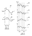
- FIG. 1 depicts a lighting system 100 that includes a triac-based leading-edge dimmer 102 and a lamp 142 .
- FIG. 2 depicts example voltage and current graphs associated with lighting system 100 .
- lighting system 100 receives an AC supply voltage V SUPPLY from voltage supply 104 .
- the supply voltage V SUPPLY is, for example, a nominally 60 Hz/110 V line voltage in the United States of America or a nominally 50 Hz/220 V line voltage in Europe.
- Triac 106 acts as a voltage-driven switch, and a gate terminal 108 of triac 106 controls current flow between the first terminal 110 and the second terminal 112 .
- a gate voltage V G on the gate terminal 108 above a firing threshold voltage value V F will cause triac 106 to turn ON, in turn causing a short of capacitor 121 and allowing current to flow through triac 106 and dimmer 102 to generate an output current i DIM .
- the dimmer output voltage V ⁇ _ DIM is zero volts from the beginning of each of half cycles 202 and 204 at respective times t 0 and t 2 until the gate voltage V G reaches the firing threshold voltage value V F .
- Dimmer output voltage V ⁇ _ DIM represents the output voltage of dimmer 102 .
- the dimmer 102 chops or cuts the supply voltage V SUPPLY so that the dimmer output voltage V ⁇ _ DIM remains at zero volts during time period t OFF .
- the gate voltage V G reaches the firing threshold value V F , and triac 106 begins conducting. Once triac 106 turns ON, the dimmer voltage V ⁇ _ DIM tracks the supply voltage V SUPPLY during time period t ON .
- triac 106 Once triac 106 turns ON, the current i DIM drawn from triac 106 must exceed an attach current i ATT in order to sustain the inrush current through triac 106 above a threshold current necessary for opening triac 106 . In addition, once triac 106 turns ON, triac 106 continues to conduct current i DIM regardless of the value of the gate voltage V G as long as the current i DIM remains above a holding current value i HC .
- the attach current value i ATT and the holding current value i HC is a function of the physical characteristics of the triac 106 . Once the current i DIM drops below the holding current value i HC , i.e.
- triac 106 turns OFF (i.e., stops conducting), until the gate voltage V G again reaches the firing threshold value V F .
- the holding current value i HC is generally low enough so that, ideally, the current i DIM drops below the holding current value i HC when the supply voltage V SUPPLY is approximately zero volts near the end of the half cycle 202 at time t 2 .
- variable resistor 114 in series with the parallel connected resistor 116 and capacitor 118 form a timing circuit 115 to control the time t 1 at which the gate voltage V G reaches the firing threshold value V F .
- Increasing the resistance of variable resistor 114 increases the time t OFF , and decreasing the resistance of variable resistor 114 decreases the time t OFF .
- the resistance value of the variable resistor 114 effectively sets a dimming value for lamp 142 .
- Diac 119 provides current flow into the gate terminal 108 of triac 106 .
- the dimmer 102 also includes an inductor choke 120 to smooth the dimmer output voltage V ⁇ _ DIM .
- Triac-based dimmer 102 also includes a capacitor 121 connected across triac 106 and inductor choke 120 to reduce electro-magnetic interference.
- modulating the phase angle of the dimmer output voltage V ⁇ _ DIM effectively turns the lamp 142 OFF during time period t OFF and ON during time period t ON for each half cycle of the supply voltage V SUPPLY .
- the dimmer 102 effectively controls the average energy supplied to lamp 142 in accordance with the dimmer output voltage V ⁇ _ DIM .
- the triac-based dimmer 102 adequately functions in many circumstances, such as when lamp 142 consumes a relatively high amount of power, such as an incandescent light bulb. However, in circumstances in which dimmer 102 is loaded with a lower-power load (e.g., a light-emitting diode or LED lamp), such load may draw a small amount of current i DIM , and it is possible that the current i DIM may fail to reach the attach current i ATT and also possible that current i DIM may prematurely drop below the holding current value i HC before the supply voltage V SUPPLY reaches approximately zero volts.
- a lower-power load e.g., a light-emitting diode or LED lamp
- dimmer 102 may prematurely disconnect and may not pass the appropriate portion of input voltage V SUPPLY to its output. If the current i DIM prematurely drops below the holding current value i HC , the dimmer 102 prematurely shuts down, and the dimmer voltage V ⁇ _ DIM will prematurely drop to zero. When the dimmer voltage V ⁇ _ DIM prematurely drops to zero, the dimmer voltage V ⁇ _ DIM does not reflect the intended dimming value as set by the resistance value of variable resistor 114 .
- the ON time period t ON prematurely ends at a time earlier than t 2 instead of ending at time t 2 , thereby decreasing the amount of energy delivered to the load.
- the energy delivered to the load will not match the dimming level corresponding to the dimmer voltage V ⁇ _ DIM .
- V ⁇ _ DIM prematurely drops to zero, charge may accumulate on capacitor 118 and gate 108 , causing triac 106 to again refire if V G exceeds V F during the same half cycle 202 or 204 , and/or causing triac 106 to fire incorrectly in subsequent half cycles due to such accumulated charge.
- premature disconnection of triac 106 may lead to errors in the timing circuitry of dimmer 102 and instability in its operation.
- Dimming a light source with dimmers saves energy when operating a light source and also allows a user to adjust the intensity of the light source to a desired level.
- conventional dimmers such as a triac-based leading-edge dimmer, that are designed for use with resistive loads, such as incandescent light bulbs, often do not perform well when attempting to supply a raw, phase modulated signal to a reactive load such as an electronic power converter or transformer.
- Transformers present in a power infrastructure may include magnetic or electronic transformers.
- a magnetic transformer typically comprises two coils of conductive material (e.g., copper) each wrapped around of core of material having a high magnetic permeability (e.g., iron) such that magnetic flux passes through both coils.
- a magnetic transformer may step voltage levels up or down while providing electrical isolation in a circuit between components coupled to the primary winding and components coupled to the secondary winding.
- an electronic transformer is a device which behaves in the same manner as a conventional magnetic transformer in that it steps voltage levels up or down while providing isolation and can accommodate load current of any power factor.
- An electronic transformer generally includes power switches which convert a low-frequency (e.g., direct current to 400 Hertz) voltage wave to a high-frequency voltage wave (e.g., in the order of 10,000 Hertz).
- a comparatively small magnetic transformer may be coupled to such power switches and thus provides the voltage level transformation and isolation functions of the conventional magnetic transformer.
- FIG. 3 depicts a lighting system 101 that includes a triac-based leading-edge dimmer 102 (e.g., such as that shown in FIG. 1 ), a magnetic transformer 122 , and a lamp 142 .
- a triac-based leading-edge dimmer 102 e.g., such as that shown in FIG. 1
- a magnetic transformer 122 e.g., such as that shown in FIG. 1
- a lamp 142 e.g., a lamp 142 .
- Such a system may be used, for example, to transform a high voltage (e.g., 110V, 220 V) to a low voltage (e.g., 12 V) for use with a halogen lamp (e.g., an MR16 halogen lamp).
- FIG. 4 depicts example voltage and current graphs associated with lighting system 101 . Referring to FIGS.
- FIG. 3 an equivalent circuit model for transformer 122 that represents the physical behavior of a magnetic transformer is depicted in FIG. 3 .
- Parasitic effects present in transformer 122 are represented in an equivalent circuit model for transformer 122 by a primary side parasitic inductance 124 (with an inductance L p ) in series with a primary side parasitic resistance 126 (with a resistance R p ) and a secondary side parasitic inductance 132 (with an inductance L s ) in series with a secondary side parasitic resistance 134 (with an resistance R s ), which model losses and leakage reactances of the transformer coils.
- Parasitic effects are also represented by a “magnetizing branch” of the model comprising shunt leg parasitic inductance 128 (with an inductance L m ) in parallel with a shunt leg parasitic resistance 130 (with a resistance R m ), which model losses and leakage reactances of the transformer core.
- a magnetizing current I m flows to the shunt leg reactance representing current required to maintain mutual magnetic flux in the core.
- FIG. 4 depicts example waveforms for dimmer 102 output voltage V ⁇ _ DIM 402 , secondary voltage V s 404 , magnetizing current i m 406 , and the current i s /N 408 through the primary winding of transformer 122 , assuming a three-wire dimmer.
- the waveform V ⁇ _ DIM 402 shown in FIG. 4 differs from that of waveform V ⁇ _ DIM 206 shown in FIG. 2 due to reactances present in transformer 122 , and in particular the presence of magnetizing current I m .
- a magnetizing current i m 406 remains flowing in transformer 122 and may account for significantly all of the current i DIM , thus inducing a voltage V s 404 rising in magnitude.
- primary winding current i s /N may also begin increasing above zero.
- the dimmer may again turn on (e.g., i DIM >i ATT ), and a magnetizing current i m and primary winding current i s /N may again appear.
- i DIM i s /N+i m
- phase-cutting dimmer is known as a trailing-edge dimmer
- FIG. 5 depicts a lighting system 500 that includes a trailing-edge, phase-cut dimmer 502 and a lamp 542 .
- FIG. 6 depicts example voltage and current graphs associated with lighting system 500 .
- lighting system 500 receives an AC supply voltage V SUPPLY from voltage supply 504 .
- the supply voltage V SUPPLY indicated by voltage waveform 602 , is, for example, a nominally 60 Hz/110 V line voltage in the United States of America or a nominally 50 Hz/220 V line voltage in Europe.
- Trailing edge dimmer 502 phase cuts trailing edges, such as trailing edges 602 and 604 , of each half cycle of supply voltage V SUPPLY .
- the trailing edge dimmer 502 phase cuts the supply voltage V SUPPLY at an angle greater than 0 degrees and less than 180 degrees.
- the phase cut, input voltage V ⁇ _ DIM to lamp 542 represents a dimming level that causes the lighting system 500 to adjust power delivered to lamp 542 , and, thus, depending on the dimming level, increase or decrease the brightness of lamp 542 .
- Dimmer 502 includes a timer controller 510 that generates dimmer control signal DCS to control a duty cycle of switch 512 .
- the duty cycle of switch 512 is a pulse width (e.g., times t 1 ⁇ t 0 ) divided by a period of the dimmer control signal (e.g., times t 3 ⁇ t 0 ) for each cycle of the dimmer control signal DCS.
- Timer controller 510 converts a desired dimming level into the duty cycle for switch 512 .
- the duty cycle of the dimmer control signal DCS is decreased for lower dimming levels (i.e., higher brightness for lamp 542 ) and increased for higher dimming levels.
- switch 512 conducts (i.e., is “on”), and dimmer 502 enters a low resistance state.
- the resistance of switch 512 is, for example, less than or equal to 10 ohms.
- the phase cut, input voltage V ⁇ _ DIM tracks the input supply voltage V SUPPLY and dimmer 502 transfers a dimmer current i DIM to lamp 542 .
- dimmer control signal 606 turns switch 512 off, which causes dimmer 502 to enter a high resistance state (i.e., turns off).
- the resistance of switch 512 is, for example, greater than 1 kiloohm.
- Dimmer 502 includes a capacitor 514 , which charges to the supply voltage V SUPPLY during each pulse of the timer control signal DCS. In both the high and low resistance states of dimmer 502 , the capacitor 514 remains connected across switch 512 .
- the voltage V C across capacitor 514 increased (e.g., between times t 1 and t 2 and between times t 4 and t 5 ).
- the rate of increase is a function of the amount of capacitance C of capacitor 514 and the input impedance of lamp 542 . If effective input resistance of lamp 542 is low enough, it permits a high enough value of the dimmer current i DIM to allow the phase cut, input voltage V ⁇ _ DIM to decay to a zero crossing (e.g., at times t 2 and t 5 ) before the next pulse of the dimmer control signal DCS.
- Dimming a light source with dimmers saves energy when operating a light source and also allows a user to adjust the intensity of the light source to a desired level.
- conventional dimmers such as a trailing-edge dimmer, that are designed for use with resistive loads, such as incandescent light bulbs, often do not perform well when supplying a raw, phase modulated signal to a reactive load such as a power converter or transformer, as is discussed in greater detail below.
- FIG. 7 depicts a lighting system 500 that includes a trailing-edge, phase-cut dimmer 502 , an electronic transformer 522 , and a lamp 542 .
- a lighting system 500 may be used, for example, to transform a high voltage (e.g., 110V, 220 V) to a low voltage (e.g., 12 V) for use with a halogen lamp (e.g., an MR16 halogen lamp).
- FIG. 8 depicts example voltage graphs associated with lighting system 501 .
- electronic transformer 522 may receive the dimmer output voltage V ⁇ _ DIM at its input where it is rectified by a full-bridge rectifier formed by diodes 524 .
- voltage on capacitor 526 may increase to a point where diac 528 will turn on, thus also turning on transistor 529 .
- transistor 529 Once transistor 529 is on, capacitor 526 may be discharged and oscillation will start due to the self-resonance of switching transformer 530 , which includes a primary winding (T 2a ) and two secondary windings (T 2b and T 2c ). Accordingly, as depicted in FIG. 8 , an oscillating output voltage V s 800 will be formed on the secondary of transformer 532 and delivered to lamp 542 while dimmer 502 is on, bounded by an AC voltage level proportional to V ⁇ _ DIM .
- lamp 542 may draw sufficient current to allow transformer 522 to sustain oscillation.
- a lower-power lamp such as a six-watt LED bulb
- the current drawn by lamp 542 may be insufficient to sustain oscillation in transformer 522 , which may lead to unreliable effects, such as visible flicker and a reduction in total light output below the level indicated by the dimmer
- an apparatus may include a controller to provide compatibility between a load and a secondary winding of a transformer driven at its primary winding by a dimmer, wherein the controller is configured to: determine from a transformer secondary signal whether the transformer comprises a magnetic transformer or an electronic transformer; and select a compatibility mode of operation from a plurality of modes of operation based on the determination of whether the transformer comprises a magnetic transformer or an electronic transformer.
- a method for providing compatibility between a load and a secondary winding of a transformer driven at its primary winding by a dimmer may include determining from a transformer secondary signal whether the transformer comprises a magnetic transformer or an electronic transformer and selecting a compatibility mode of operation from a plurality of modes of operation based on the determination of whether the transformer comprises a magnetic transformer or an electronic transformer.
- an apparatus may include a controller to provide compatibility between a load and a secondary winding of a magnetic transformer driven at its primary winding by a trailing-edge dimmer, wherein the controller is configured to determine from a magnetic transformer secondary signal a period of a half-line cycle of an output signal of the dimmer, determine from the magnetic transformer secondary signal an estimated occurrence of an end of a phase-cut angle of the dimmer, generate a driving signal to the load based on the period and the estimated occurrence of the end of the phase-cut angle.
- a method for providing compatibility between a load and a secondary winding of a magnetic transformer driven at its primary winding by a trailing-edge dimmer may include determining from a magnetic transformer secondary signal a period of a half-line cycle of an output signal of the dimmer, determining from the magnetic transformer secondary signal an estimated occurrence of an end of a phase-cut angle of the dimmer, and generating a driving signal to the load based on the period and the estimated occurrence of the end of the phase-cut angle.
- a lamp assembly may include a lamp for generating light and a controller for controlling operation of the lamp, the controller comprising a timing control circuit for determining a period of a periodic signal received by the lamp assembly.
- an apparatus may include a controller to provide compatibility between a load and a secondary winding of an electronic transformer driven by a trailing-edge dimmer, wherein the controller is configured to predict based on an electronic transformer secondary signal an estimated occurrence of a high-resistance state of the trailing-edge dimmer, wherein the high-resistance state occurs when the trailing-edge dimmer begins phase-cutting an alternating current voltage signal and operate in a high-current mode for a period of time immediately prior to the estimated occurrence of the high-resistance state.
- a method for providing compatibility between a load and a secondary winding of an electronic transformer driven by a trailing-edge dimmer may include predicting based on of an electronic transformer secondary signal an estimated occurrence of a high-resistance state of the trailing-edge dimmer, wherein the high-resistance state occurs when the trailing-edge dimmer begins phase-cutting an alternating current voltage signal and operating the load in a high-current mode for a period of time immediately prior to the estimated occurrence of the high-resistance state.
- FIG. 1 illustrates a lighting system that includes a triac-based leading-edge dimmer, as is known in the art
- FIG. 2 illustrates example voltage and current graphs associated with the lighting system depicted in FIG. 1 , as is known in the art;
- FIG. 3 illustrates a lighting system that includes a triac-based leading-edge dimmer and a magnetic transformer, as is known in the art
- FIG. 4 illustrates example voltage and current graphs associated with the lighting system depicted in FIG. 3 , as is known in the art;
- FIG. 5 illustrates a lighting system that includes a phase-cut trailing-edge dimmer, as is known in the art
- FIG. 6 illustrates example voltage and current graphs associated with the lighting system depicted in FIG. 5 , as is known in the art
- FIG. 7 illustrates a lighting system that includes a phase-cut trailing-edge dimmer and an electronic transformer, as is known in the art
- FIG. 8 illustrates example voltage and current graphs associated with the lighting system depicted in FIG. 7 , as is known in the art
- FIG. 9 illustrates an example lighting system including a controller for providing compatibility between a low-power lamp and other elements of a lighting system, in accordance with embodiments of the present disclosure
- FIG. 10 illustrates an example transformer detection module, in accordance with embodiments of the present disclosure
- FIGS. 11A and 11B illustrate example voltage graphs associated with the transformer detection module illustrated in FIG. 10 , in accordance with embodiments of the present disclosure
- FIG. 12 illustrates the example lighting system of FIG. 9 , with detail illustrating example components of a current control module for operating in a magnetic transformer compatibility mode of operation, in accordance with embodiments of the present disclosure
- FIG. 13 illustrates the example lighting system of FIG. 9 , with detail illustrating example components of a current control module for operating in an electronic transformer compatibility mode of operation, in accordance with embodiments of the present disclosure
- FIG. 14 depicts example voltage and current graphs associated with the lighting system depicted in FIG. 13 , in accordance with embodiments of the present disclosure.
- FIG. 15 illustrates a flow chart of an example method 1500 for ensuring compatibility between a lamp and a transformer driver by a dimmer, in accordance with embodiments of the present disclosure.
- FIG. 9 illustrates an example lighting system 900 including a controller 912 for providing compatibility between a low-power lamp 942 and other elements of a lighting system, in accordance with embodiments of the present disclosure.
- lightning system 900 may include a voltage supply 904 , a dimmer 902 , a transformer 922 , a lamp 942 , and a controller 912 .
- Voltage supply 904 may generate a supply voltage V SUPPLY that is, for example, a nominally 60 Hz/110 V line voltage in the United States of America or a nominally 50 Hz/220 V line voltage in Europe.
- Dimmer 902 may comprise any system, device, or apparatus for generating a dimming signal to other elements of lighting system 900 , the dimming signal representing a dimming level that causes lighting system 900 to adjust power delivered to a lamp, and, thus, depending on the dimming level, increase or decrease the brightness of lamp 942 .
- dimmer 902 may include a leading-edge dimmer similar or identical to that depicted in FIGS. 1 and 3 , a trailing-edge dimmer similar to that depicted in FIGS. 5 and 7 , or any other suitable dimmer
- Transformer 922 may comprise any system, device, or apparatus for transferring energy by inductive coupling between winding circuits of transformer 922 .
- transformer 922 may include a magnetic transformer similar or identical to that depicted in FIG. 3 , an electronic transformer similar to that depicted in FIG. 7 , or any other suitable transformer.
- Lamp 942 may comprise any system, device, or apparatus for converting electrical energy (e.g., delivered by transformer 922 ) into photonic energy.
- lamp 942 may comprise a multifaceted reflector form factor (e.g., an MR16 form factor).
- lamp 942 may comprise an LED lamp.
- Controller 912 may comprise any system, device, or apparatus configured to, as described in greater detail elsewhere in this disclosure, determine from analyzing a transformer secondary signal whether transformer 922 comprises a magnetic transformer or an electronic transformer, select a compatibility mode of operation from a plurality of modes of operation based on the determination of whether the transformer comprises a magnetic transformer or an electronic transformer, and operate lamp 942 in accordance with such selected compatibility mode. As shown in FIG. 9 , controller 912 may comprise a transformer detection module 914 and a current control module 918 .
- controller 912 and lamp 942 may be integral to the same lamp assembly 932 (e.g., the same package), wherein such lamp assembly 932 is configured to be electrically coupled to transformer 922 .
- Transformer detection module 914 may comprise any system, device, or apparatus configured to determine from analyzing a transformer secondary signal whether transformer 922 comprises a magnetic transformer or an electronic transformer. In some embodiments, transformer detection module 914 may be configured to determine whether transformer 922 is a magnetic transformer or an electronic transformer based on a frequency of oscillation of the transformer secondary signal. For example, if the frequency of oscillation of the transformer secondary signal is greater than a particular predetermined threshold frequency, transformer detection module 914 may determine that transformer 922 is an electronic transformer, while if the frequency of oscillation of the transformer secondary signal is lesser than the same or a different predetermined threshold frequency, transformer detection module 914 may determine that transformer 922 is a magnetic transformer. An example embodiment of transformer detection module 914 is depicted in FIG. 10 .
- transformer detection module 914 may receive an input voltage V in which may be the output voltage of transformer 922 .
- Such input voltage may be rectified by bridge rectifier 1002 and two sense resistors 1004 may be coupled to each other at a summing node and to each of a positive polarity of the input voltage and a positive polarity of the output of rectifier 1002 .
- Another resistor 1006 may be coupled between a negative polarity of the output of the rectifier and the sense resistors 1004 at the summing node in order to form a voltage divider such that a voltage v sum appears at the summing node.
- FIG. 11A depicts an example voltage waveform 1100 for voltage v sum at the summing node in the event that a magnetic transformer is present
- FIG. 11B depicts an example waveform 1150 for voltage v sum at the summing node in the event that an electronic transformer is present in accordance with embodiments of the present disclosure.
- the frequency response of the summing node in the presence of a magnetic transformer is of a much lower frequency than that of the electronic transformer.
- frequency detector 1008 which may comprise any suitable system, device or apparatus for detecting the frequency of a periodic signal as is known by those in the art, may determine whether the frequency at the summing node is greater than a particular predetermined threshold frequency, and thus output a transformer indication signal indicating the presence of an electronic transformer, or may determine whether the frequency at the summing node is less than the same or a different predetermined threshold frequency, and thus output a transformer indication signal indicating presence of a magnetic transformer.
- frequency detector 1008 may also be able to determine phase imbalances between the phases of waveform 1100 based on different waveform amplitudes between the phases. Based on such determination, current control module 918 may determine current drawn from magnetic transformer 922 in each phase and correct for such imbalance, as described below.
- current control module 918 may receive the transformer indication signal from transformer detection module 914 and, based on such signal, operate in one of a plurality of compatibility modes of operation, as described in greater detail elsewhere in this disclosure. For example, if the transformer indication signal indicates that transformer 922 is a magnetic transformer, current control module 918 may operate in a magnetic transformer compatibility mode of operation. Alternatively, if the transformer indication signal indicates that transformer 922 is an electronic transformer, current control module 918 may operate in an electronic transformer compatibility mode of operation.
- FIG. 12 illustrates the example lighting system 900 of FIG. 9 , with detail illustrating example components of current control module 918 for operating in a magnetic transformer compatibility mode of operation in accordance with embodiments of the present disclosure.
- current control module 918 may include components for operating in an electronic transformer compatibility mode of operation, such components are not depicted in FIG. 12 .
- current control module 918 may include a timing control circuit 1202 , a phase cut detection circuit 1204 , and driving signal generator 1206 .
- Timing control circuit 1202 may be any system, device, or apparatus configured to analyze a signal (e.g., transformer secondary voltage signal V s ) to determine a period of a half-line cycle of an output signal of dimmer 902 .
- a signal e.g., transformer secondary voltage signal V s
- timing control circuit 1202 may comprise a phase-locked loop.
- timing control circuit 1202 may comprise a delay-locked loop.
- Timing control circuit 1202 may communicate a signal T period indicative of the determined period of the half-line cycle to phase cut detection circuit 1204 .
- Phase cut detection circuit 1204 may comprise any system, device, or apparatus configured to analyze a signal (e.g., transformer secondary voltage signal V s ) to determine an estimated occurrence of an end of a phase-cut angle of dimmer 902 and based on the half-line cycle period and estimated occurrence of the end of the phase-cut angle, generate a signal indicative of the portion of the half-line cycle period in which dimmer 902 is active (e.g., ON). Phase cut detection circuit 1204 may communicate a signal T active indicative of the portion of the half-line cycle period in which dimmer 902 is active to driving signal generator 1206 .
- a signal e.g., transformer secondary voltage signal V s
- phase cut detection circuit 1204 may be configured to determine the estimated occurrence of the end of the phase-cut angle based on at least a determination of an estimated time at which transformer secondary voltage signal V s exceeds a predetermined threshold magnitude (e.g., so as to detect the occurrence of times analogous to times t 1 , t 1 ′ depicted in FIG. 4 ).
- phase cut detection circuit 1204 may be configured to determine the estimated occurrence of the end of the phase-cut angle based on at least a determination of an estimated time at which transformer secondary voltage signal V s falls below a predetermined threshold magnitude (e.g., so as to detect the occurrence of times analogous to times t 3 , t 3 ′ depicted in FIG. 4 ).
- phase cut detection circuit 1204 may be configured to determine the estimated occurrence of the end of the phase-cut angle based on at least a determination of an estimated continuous period of time in which transformer secondary voltage signal V s remains above a predetermined threshold magnitude. Such determination of a time or times in reference to one or more threshold magnitudes may be performed in any suitable manner, including use of one or more comparator circuits to determine the occurrence or occurrences of threshold crossing. Based on a further comparison of the timing of the estimated occurrence of such a threshold crossing relative to the signal periodicity generated by timing control circuit 1202 , phase cut detection circuit 1204 may be able to determine the portion of the half-line cycle period in which dimmer 902 is active.
- driving signal generator 1206 may, based on a phase imbalance determined by transformer detection module, correct for such imbalance to make up for differing amplitudes flowing from transformer 922 .
- Driving signal generator 1206 may comprise any system, device, or apparatus for receiving a signal indicative of a portion of a half-line cycle period in which dimmer 902 is active and based on such signal, generate a driving signal indicative of an intensity of light to be generated by lamp 942 , and communicate such driving signal to lamp 942 .
- driving signal generator 1206 may be configured to apply a mathematical function (e.g., a linear or polynomial function) to convert the signal indicative of a portion of a half-line cycle period in which dimmer 902 is active to the driving signal.
- driving signal 1206 may comprise a lookup table or other similar data structure in which various driving signal levels are indexed by values for the signal indicative of a portion of a half-line cycle period in which dimmer 902 is active.
- FIG. 13 illustrates the example lighting system 900 of FIG. 9 , with detail illustrating example components of current control module 918 for operating in an electronic transformer compatibility mode of operation.
- FIG. 14 depicts example voltage and current graphs associated with lighting system 900 depicted in FIG. 13 , in accordance with embodiments of the present disclosure.
- current control module 918 may include components for operating in a magnetic transformer compatibility mode of operation, such components are not depicted in FIG. 13 .
- current control circuit 918 may include a trailing edge estimator 1302 , trigger event estimator 1304 , mode controller 1306 , and accumulator 1308 .
- Trailing edge estimator 1302 may include any system, device, or apparatus configured to, based on analysis of a transformer secondary signal V s , predict an estimated occurrence of a high-resistance state of dimmer 902 , the high-resistance state occurring when the dimmer begins phase-cutting an alternating current voltage signal (e.g., where dimmer 902 is a trailing-edge dimmer, the trailing edge).
- trailing edge estimator 1302 may predict or estimate the occurrence of times labeled t 1 and t 4 .
- the estimated occurrence of the high-resistance state may be predicted in any suitable manner, for example, using systems and methods disclosed in U.S.
- Trailing edge estimator 1302 may communicate a trailing edge estimate signal indicative of the estimated occurrence of a high-resistance state of dimmer 902 to mode controller 1306 .
- Trigger event estimator 1304 may include any system, device, or apparatus configured to, based on analysis of a transformer secondary signal V s , predict an estimated occurrence of a trigger event of the electronic transformer, the trigger event corresponding to a rise in an output voltage of dimmer 902 . Thus, referring to FIG. 14 , trigger event estimator 1304 may predict or estimate the occurrence of times labeled t 0 and t 3 . In some embodiments, trigger event estimator 1304 may estimate the occurrence of the trigger event by determining a time at which voltage V s exceeds a threshold trigger voltage V TRIG .
- Trigger event estimator 1304 may communicate a trigger event estimate signal indicative of the estimated occurrence of the trigger event to mode controller 1306 .
- Mode controller 1306 may include any system, device, or apparatus configured to, based on a trailing edge estimate signal communicated from trailing edge estimator 1302 , a trigger event estimate signal communicated from trigger event estimator 1304 , and/or an accumulated error signal communicated from accumulator 1308 , generate a mode select signal in order to select a particular mode for lamp 942 . For example, as shown by the waveform for lamp 942 current i LOAD on FIG.
- mode controller 1306 may cause current control module 918 (and thus lamp 942 ) to operate in a high-current mode from a period beginning at a high-current mode start time t HC and ending at approximately the estimated occurrence of the high-resistance state of dimmer 902 , (e.g., a time t 2 or t 5 , once voltage V S has decayed to zero).
- Such control setting of dimmer 902 is thus estimated based on the estimated occurrence of a high-resistance state of dimmer 902 as indicated by the trailing edge estimate signal and the estimated occurrence of the trigger event as indicated by the trailing edge estimate signal.
- Mode controller 1306 may determine the high-current mode start time t HC based on the accumulated error signal communicated from accumulator 1308 in order to correct for errors in the amount of energy delivered to lamp 942 in previously occurring cycles of voltage V s , as described in greater detail below.
- mode controller 1306 may cause current control module 918 (and thus lamp 942 ) to operate in a low-impedance mode from a period beginning at the high-resistance state of dimmer 902 (e.g., a time t 2 or t 5 ) and ending at the subsequent trigger event time t TRIG .
- output voltages of dimmer 902 and transformer 922 may be kept low in order to permit dimmer 902 to reset for its next phase-cut cycle.
- mode controller 1306 may cause current control module 918 (and thus lamp 942 ) to operate in a high-impedance mode from a period beginning at the trigger event time t TRIG and ending at the beginning of the subsequent high-current mode occurring at a time t HC .
- mode controller 1306 may, based on a trailing edge estimate signal communicated from trailing edge estimator 1302 , a trigger event estimate signal communicated from trigger event estimator 1304 , and/or an accumulated error signal communicated from accumulator 1308 , sequentially and cyclically operate in the high-current mode, the low-impedance mode, and the high-impedance mode.
- Mode controller 1306 may additionally be configured to, during each particular operation in the high-current mode, determine a target amount of energy to be delivered to lamp 942 during the particular operation of the high-current mode. In some embodiments, such target amount of energy may be based on a control setting of dimmer 902 , and an estimate of such control setting may be made by calculating the aggregate duration of the high-current mode and the high-impedance mode. In addition, mode controller 1306 may be configured to, during the particular operation of the high-current mode, determine an estimated delivered amount of energy actually delivered to lamp 942 . In some embodiments, such estimated delivered amount of energy may be calculated based on the duration of the high-current mode. Furthermore, mode controller 1306 may be configured to calculate an error based on the difference between the target amount of energy and the estimated delivered amount of energy, and calculate an error signal to accumulator 1308 based on such error.
- Accumulator 1308 may include any system, device, or apparatus configured to, based on an error signal communicated from mode controller 1306 , calculate an accumulated error accumulated during multiple preceding operations in the high-current mode, and communicate an accumulated error signal to mode controller 1306 indicative of such accumulated error. As discussed above, such accumulated error signal may be used by mode controller 1306 to determine a duration of a high-current mode (e.g., high-current mode start time t HC may be modulated as a function of the accumulated error). Thus, an error accumulated during one or more operations in the high-current mode may be corrected, in whole or part, in one or more subsequent operations in the high-current mode by varying the duration of high-current modes.
- a high-current mode e.g., high-current mode start time t HC may be modulated as a function of the accumulated error.
- mode controller 1306 may correct for error by causing the duration for a particular operation in the high-current mode to begin at the estimated occurrence of the trigger event, as shown by pulse 1402 in FIG. 14 .
- An operation in the high-current mode having such a duration may be referred to as a “probe event.”
- mode controller 1306 may cause a probe event to occur for each n-th operation of the high-current mode, where n is a positive integer. In particular embodiments, n may be an odd positive integer. When a probe event occurs, mode controller 1306 may eliminate the high-impedance mode that would have otherwise occurred immediately preceding the high-current mode comprising the probe event.
- FIG. 15 illustrates a flow chart of an example method 1500 for ensuring compatibility between a lamp and a transformer driver by a dimmer, in accordance with embodiments of the present disclosure.
- method 1500 may begin at step 1502 .
- teachings of the present disclosure may be implemented in a variety of configurations of lighting system 900 . As such, the preferred initialization point for method 1500 and the order of the steps comprising method 1500 may depend on the implementation chosen.
- controller 912 may determine the transformer type of transformer 922 . Controller 912 may make such determination based on a frequency of oscillation of a secondary voltage signal (e.g., V s ) of transformer 922 , as described elsewhere in this disclosure. If controller 912 determines transformer 922 to be a magnetic transformer, method 1500 may proceed to step 1504 . Otherwise, if controller 912 determines transformer 922 to be an electronic transformer, method 1500 may proceed to step 1510 .
- V s secondary voltage signal
- controller 912 may analyze the voltage signal of the secondary of transformer 922 to determine a period of a half-line cycle of an output signal of dimmer 902 . In some embodiments, such determination may be made by a timing control circuit (e.g., a phase-locked loop or a delay-locked loop).
- a timing control circuit e.g., a phase-locked loop or a delay-locked loop.
- controller 912 may analyze the voltage signal of the secondary of transformer 922 to determine an estimated occurrence of an end of a phase-cut angle of dimmer 902 . Controller 912 may determine the estimated occurrence of the end of the phase cut angle based at least on: (a) a determination of an estimated time at which the voltage of transformer 922 secondary exceeds a predetermined threshold magnitude; (b) a determination of an estimated time at which the voltage of transformer 922 falls below the same or a different predetermined threshold magnitude; and/or (c) a determination of an estimated portion of the period in which the magnetic transformer secondary signal is greater than the same or a different predetermined threshold magnitude.
- controller 912 may generate a driving signal to lamp 942 based on the period and the estimated occurrence of the end of the phase-cut angle, the driving signal indicative of intensity of light to be generated by lamp 942 .
- method 1500 may return to step 1504 , and steps 1504 to 1508 may repeat indefinitely.
- controller 912 may determine if the subsequent operation in the high-current mode is a probe event. Such probe event may occur for each n-th operation in the high-current mode, where n is a positive integer, and in some embodiments is an odd positive integer. If the subsequent operation in the high-current mode is a probe event, method 1500 may proceed to step 1514 , where the period of the operation in the high-current mode may run from the subsequent estimated occurrence of the trigger event to the subsequent estimated occurrence of the high-resistance state of dimmer 902 . Otherwise, if the subsequent operation in the high-current mode is not a probe event, method 1500 may proceed to step 1512 .
- controller 912 may operate in a high-impedance mode.
- controller 912 may operate in a high-current mode for a period of time immediately prior to the occurrence of the low-impedance mode.
- the period of time may be based on a control setting of dimmer 902 , and such control setting of dimmer 902 may be estimated based on the estimated occurrence of a high-resistance state of dimmer 902 as indicated by the trailing edge estimate signal and the estimated occurrence of the trigger event as indicated by the trailing edge estimate signal.
- Mode controller 1306 may determine the period of time of the high-current mode based on the accumulated error signal communicated from accumulator 1308 in order to correct for errors in the amount of energy delivered to lamp 942 in previously occurring cycles of steps 1510 to 1522 , as described in greater detail elsewhere in this disclosure.
- controller 912 may calculate an error for the operation of the high-current mode occurring at step 1514 .
- the error may be calculated as a difference between a target amount of energy to be delivered to lamp 942 during the operation in the high-current mode and an estimated delivered amount of energy actually delivered to lamp 942 during the operation in the high-current mode.
- the target amount of energy may be based on a control setting of dimmer 902 , which control setting may be estimated based on a period of time between the estimated occurrence of the trigger event and the estimated occurrence of the high-resistance state of dimmer 902 .
- the estimated amount of delivered energy may be estimated based on the period of time of the high-current mode.
- Controller 912 may add such calculated error to an accumulated error representing an aggregation of errors from previous operations in the high-current mode. Such accumulated error may be used by controller 912 in determining the period of time for subsequent operations in the high-current mode.
- controller 912 may predict based on analysis of the voltage signal of the secondary of transformer 922 an estimated occurrence of a high-resistance state of the dimmer 902 (e.g., when dimmer 902 begins phase-cutting an AC voltage signal at its input).
- controller 912 may operate in a low-impedance mode.
- controller 912 may predict an estimated occurrence of a trigger event of transformer 922 , the trigger event corresponding to a rise in an output voltage of dimmer 902 .
- method 1500 may proceed again to step 1510 , and steps 1510 to 1522 may repeat indefinitely.
- FIG. 15 discloses a particular number of steps to be taken with respect to method 1500
- method 1500 may be executed with greater or lesser steps than those depicted in FIG. 15 .
- FIG. 15 discloses a certain order of steps to be taken with respect to method 1500
- the steps comprising method 1500 may be completed in any suitable order.
- Method 1500 may be implemented using controller 912 or any other system operable to implement method 1500 .
- method 1500 may be implemented partially or fully in software and/or firmware embodied in computer-readable media.
- references in the appended claims to an apparatus or system or a component of an apparatus or system being adapted to, arranged to, capable of, configured to, enabled to, operable to, or operative to perform a particular function encompasses that apparatus, system, or component, whether or not it or that particular function is activated, turned on, or unlocked, as long as that apparatus, system, or component is so adapted, arranged, capable, configured, enabled, operable, or operative.
Abstract
Description
Claims (18)
Priority Applications (4)
| Application Number | Priority Date | Filing Date | Title |
|---|---|---|---|
| US13/799,010 US9655202B2 (en) | 2012-07-03 | 2013-03-13 | Systems and methods for low-power lamp compatibility with a leading-edge dimmer and a magnetic transformer |
| EP13736704.1A EP2870829A2 (en) | 2012-07-03 | 2013-06-26 | Systems and methods for low-power lamp compatibility with a leading-edge dimmer and a magnetic transformer |
| CN201380035740.2A CN104412711B (en) | 2012-07-03 | 2013-06-26 | For providing compatible method and its lighting device between load and transformer |
| PCT/US2013/047844 WO2014008062A2 (en) | 2012-07-03 | 2013-06-26 | Systems and methods for low-power lamp compatibility with a leading-edge dimmer and a magnetic transformer |
Applications Claiming Priority (3)
| Application Number | Priority Date | Filing Date | Title |
|---|---|---|---|
| US201261667685P | 2012-07-03 | 2012-07-03 | |
| US201261673111P | 2012-07-18 | 2012-07-18 | |
| US13/799,010 US9655202B2 (en) | 2012-07-03 | 2013-03-13 | Systems and methods for low-power lamp compatibility with a leading-edge dimmer and a magnetic transformer |
Publications (2)
| Publication Number | Publication Date |
|---|---|
| US20140009079A1 US20140009079A1 (en) | 2014-01-09 |
| US9655202B2 true US9655202B2 (en) | 2017-05-16 |
Family
ID=49878001
Family Applications (3)
| Application Number | Title | Priority Date | Filing Date |
|---|---|---|---|
| US13/799,010 Expired - Fee Related US9655202B2 (en) | 2012-07-03 | 2013-03-13 | Systems and methods for low-power lamp compatibility with a leading-edge dimmer and a magnetic transformer |
| US13/799,329 Active US9072125B2 (en) | 2012-07-03 | 2013-03-13 | Systems and methods for determining a type of transformer to which a load is coupled |
| US13/798,926 Expired - Fee Related US9167664B2 (en) | 2012-07-03 | 2013-03-13 | Systems and methods for low-power lamp compatibility with a trailing-edge dimmer and an electronic transformer |
Family Applications After (2)
| Application Number | Title | Priority Date | Filing Date |
|---|---|---|---|
| US13/799,329 Active US9072125B2 (en) | 2012-07-03 | 2013-03-13 | Systems and methods for determining a type of transformer to which a load is coupled |
| US13/798,926 Expired - Fee Related US9167664B2 (en) | 2012-07-03 | 2013-03-13 | Systems and methods for low-power lamp compatibility with a trailing-edge dimmer and an electronic transformer |
Country Status (4)
| Country | Link |
|---|---|
| US (3) | US9655202B2 (en) |
| EP (2) | EP2870829A2 (en) |
| CN (2) | CN104584688B (en) |
| WO (2) | WO2014008055A2 (en) |
Cited By (1)
| Publication number | Priority date | Publication date | Assignee | Title |
|---|---|---|---|---|
| US20170164438A1 (en) * | 2014-06-17 | 2017-06-08 | Philips Lighting Holding B.V. | Dynamic control circuit |
Families Citing this family (52)
| Publication number | Priority date | Publication date | Assignee | Title |
|---|---|---|---|---|
| US7288902B1 (en) | 2007-03-12 | 2007-10-30 | Cirrus Logic, Inc. | Color variations in a dimmable lighting device with stable color temperature light sources |
| US7667408B2 (en) | 2007-03-12 | 2010-02-23 | Cirrus Logic, Inc. | Lighting system with lighting dimmer output mapping |
| US9155174B2 (en) | 2009-09-30 | 2015-10-06 | Cirrus Logic, Inc. | Phase control dimming compatible lighting systems |
| CN103025337B (en) * | 2009-11-17 | 2014-10-15 | 特锐拉克斯有限公司 | LED power-supply detection and control |
| US8729811B2 (en) | 2010-07-30 | 2014-05-20 | Cirrus Logic, Inc. | Dimming multiple lighting devices by alternating energy transfer from a magnetic storage element |
| US8536799B1 (en) | 2010-07-30 | 2013-09-17 | Cirrus Logic, Inc. | Dimmer detection |
| US9307601B2 (en) | 2010-08-17 | 2016-04-05 | Koninklijke Philips N.V. | Input voltage sensing for a switching power converter and a triac-based dimmer |
| EP2609790A2 (en) | 2010-08-24 | 2013-07-03 | Cirrus Logic, Inc. | Multi-mode dimmer interfacing including attach state control |
| WO2012061774A2 (en) | 2010-11-04 | 2012-05-10 | Cirrus Logic, Inc. | Controlled energy dissipation in a switching power converter |
| CN103262399B (en) | 2010-11-04 | 2017-02-15 | 皇家飞利浦有限公司 | Method and device for controlling energy dissipation in switch power converter |
| US8547034B2 (en) * | 2010-11-16 | 2013-10-01 | Cirrus Logic, Inc. | Trailing edge dimmer compatibility with dimmer high resistance prediction |
| CN103370990B (en) | 2010-12-16 | 2016-06-15 | 皇家飞利浦有限公司 | Based on the discontinuous mode-critical conduction mode conversion of switch parameter |
| CN103428953B (en) | 2012-05-17 | 2016-03-16 | 昂宝电子(上海)有限公司 | For the system and method utilizing system controller to carry out brightness adjustment control |
| EP2792060A2 (en) | 2011-12-14 | 2014-10-22 | Cirrus Logic, Inc. | Adaptive current control timing and responsive current control for interfacing with a dimmer |
| WO2013126836A1 (en) | 2012-02-22 | 2013-08-29 | Cirrus Logic, Inc. | Mixed load current compensation for led lighting |
| US9030115B2 (en) * | 2012-06-22 | 2015-05-12 | Abl Ip Holding Llc | LED driver with diac-based switch control and dimmable LED driver |
| US9655202B2 (en) | 2012-07-03 | 2017-05-16 | Philips Lighting Holding B.V. | Systems and methods for low-power lamp compatibility with a leading-edge dimmer and a magnetic transformer |
| US9215770B2 (en) | 2012-07-03 | 2015-12-15 | Philips International, B.V. | Systems and methods for low-power lamp compatibility with a trailing-edge dimmer and an electronic transformer |
| US9184661B2 (en) | 2012-08-27 | 2015-11-10 | Cirrus Logic, Inc. | Power conversion with controlled capacitance charging including attach state control |
| US9277624B1 (en) | 2012-10-26 | 2016-03-01 | Philips International, B.V. | Systems and methods for low-power lamp compatibility with an electronic transformer |
| CN103024994B (en) | 2012-11-12 | 2016-06-01 | 昂宝电子(上海)有限公司 | Use dimming control system and the method for TRIAC dimmer |
| US9341358B2 (en) | 2012-12-13 | 2016-05-17 | Koninklijke Philips N.V. | Systems and methods for controlling a power controller |
| US9496844B1 (en) | 2013-01-25 | 2016-11-15 | Koninklijke Philips N.V. | Variable bandwidth filter for dimmer phase angle measurements |
| US9263964B1 (en) | 2013-03-14 | 2016-02-16 | Philips International, B.V. | Systems and methods for low-power lamp compatibility with an electronic transformer |
| US9661697B2 (en) * | 2013-03-14 | 2017-05-23 | Laurence P. Sadwick | Digital dimmable driver |
| US10187934B2 (en) | 2013-03-14 | 2019-01-22 | Philips Lighting Holding B.V. | Controlled electronic system power dissipation via an auxiliary-power dissipation circuit |
| US9282598B2 (en) * | 2013-03-15 | 2016-03-08 | Koninklijke Philips N.V. | System and method for learning dimmer characteristics |
| US9502908B2 (en) * | 2013-03-29 | 2016-11-22 | Nissan Motor Co., Ltd. | Non-contact power supply system |
| US9408261B2 (en) * | 2013-05-07 | 2016-08-02 | Power Integrations, Inc. | Dimmer detector for bleeder circuit activation |
| EP2997793A1 (en) | 2013-05-13 | 2016-03-23 | Koninklijke Philips N.V. | Stabilization circuit for low-voltage lighting |
| US9635723B2 (en) | 2013-08-30 | 2017-04-25 | Philips Lighting Holding B.V. | Systems and methods for low-power lamp compatibility with a trailing-edge dimmer and an electronic transformer |
| US9521711B2 (en) | 2014-01-28 | 2016-12-13 | Philips Lighting Holding B.V. | Low-cost low-power lighting system and lamp assembly |
| US9621062B2 (en) | 2014-03-07 | 2017-04-11 | Philips Lighting Holding B.V. | Dimmer output emulation with non-zero glue voltage |
| US9215772B2 (en) * | 2014-04-17 | 2015-12-15 | Philips International B.V. | Systems and methods for minimizing power dissipation in a low-power lamp coupled to a trailing-edge dimmer |
| CN103957634B (en) | 2014-04-25 | 2017-07-07 | 广州昂宝电子有限公司 | Illuminator and its control method |
| US9385598B2 (en) | 2014-06-12 | 2016-07-05 | Koninklijke Philips N.V. | Boost converter stage switch controller |
| CN104066254B (en) | 2014-07-08 | 2017-01-04 | 昂宝电子(上海)有限公司 | TRIAC dimmer is used to carry out the system and method for intelligent dimming control |
| US9420670B1 (en) * | 2014-11-04 | 2016-08-16 | Universal Lighting Technologies, Inc. | Controller and receiver for a power line communication system |
| JP6218101B2 (en) * | 2015-06-08 | 2017-10-25 | パナソニックIpマネジメント株式会社 | Light control device |
| WO2017014778A1 (en) * | 2015-07-22 | 2017-01-26 | Halliburton Energy Services, Inc. | Improving dynamic range in fiber optic magnetic field sensors |
| WO2017069784A1 (en) * | 2015-10-23 | 2017-04-27 | Dialog Semiconductor Inc. | Switching power converter with magnetizing current shaping |
| CN106413189B (en) * | 2016-10-17 | 2018-12-28 | 广州昂宝电子有限公司 | Use the intelligence control system relevant to TRIAC light modulator and method of modulated signal |
| CN107645804A (en) | 2017-07-10 | 2018-01-30 | 昂宝电子(上海)有限公司 | System for LED switch control |
| CN107682953A (en) | 2017-09-14 | 2018-02-09 | 昂宝电子(上海)有限公司 | LED illumination System and its control method |
| CN107995730B (en) | 2017-11-30 | 2020-01-07 | 昂宝电子(上海)有限公司 | System and method for phase-based control in connection with TRIAC dimmers |
| CN108200685B (en) | 2017-12-28 | 2020-01-07 | 昂宝电子(上海)有限公司 | LED lighting system for silicon controlled switch control |
| CN109922564B (en) | 2019-02-19 | 2023-08-29 | 昂宝电子(上海)有限公司 | Voltage conversion system and method for TRIAC drive |
| CN110493913B (en) | 2019-08-06 | 2022-02-01 | 昂宝电子(上海)有限公司 | Control system and method for silicon controlled dimming LED lighting system |
| CN110831295B (en) | 2019-11-20 | 2022-02-25 | 昂宝电子(上海)有限公司 | Dimming control method and system for dimmable LED lighting system |
| CN110831289B (en) | 2019-12-19 | 2022-02-15 | 昂宝电子(上海)有限公司 | LED drive circuit, operation method thereof and power supply control module |
| CN111031635B (en) | 2019-12-27 | 2021-11-30 | 昂宝电子(上海)有限公司 | Dimming system and method for LED lighting system |
| CN111432526B (en) | 2020-04-13 | 2023-02-21 | 昂宝电子(上海)有限公司 | Control system and method for power factor optimization of LED lighting systems |
Citations (80)
| Publication number | Priority date | Publication date | Assignee | Title |
|---|---|---|---|---|
| US3806829A (en) | 1971-04-13 | 1974-04-23 | Sys Inc | Pulsed laser system having improved energy control with improved power supply laser emission energy sensor and adjustable repetition rate control features |
| US4008414A (en) | 1975-07-28 | 1977-02-15 | Power Saver Corporation | Circuit for powering fluorescent lamps |
| US4562382A (en) | 1982-11-26 | 1985-12-31 | Quietlite International Ltd. | Solid-state inverter including a multiple core transformer |
| US5040236A (en) | 1990-07-18 | 1991-08-13 | Argus International | Apparatus for irradiation of printed wiring boards and the like |
| US5089753A (en) | 1990-07-09 | 1992-02-18 | North American Philips Corporation | Arrangement for predicting failure in fluorescent lamp systems |
| US5416387A (en) | 1993-11-24 | 1995-05-16 | California Institute Of Technology | Single stage, high power factor, gas discharge lamp ballast |
| US5583402A (en) | 1994-01-31 | 1996-12-10 | Magnetek, Inc. | Symmetry control circuit and method |
| US5650694A (en) | 1995-03-31 | 1997-07-22 | Philips Electronics North America Corporation | Lamp controller with lamp status detection and safety circuitry |
| US5872429A (en) | 1995-03-31 | 1999-02-16 | Philips Electronics North America Corporation | Coded communication system and method for controlling an electric lamp |
| US6369461B1 (en) | 2000-09-01 | 2002-04-09 | Abb Inc. | High efficiency power conditioner employing low voltage DC bus and buck and boost converters |
| US6407935B1 (en) | 2000-05-30 | 2002-06-18 | Koninklijke Philips Electronics N.V. | High frequency electronic ballast with reactive power compensation |
| US20030127994A1 (en) | 2002-01-10 | 2003-07-10 | Lightech Electronic Industries Ltd. | Lamp transformer for use with an electronic dimmer and method for use thereof for reducing acoustic noise |
| US20030151931A1 (en) | 2002-02-14 | 2003-08-14 | Kazuo Kohno | Self oscillation circuits |
| US20050174162A1 (en) | 2004-02-09 | 2005-08-11 | Taiwan Semiconductor Manufacturing Company | Configurable voltage generator |
| US20050249667A1 (en) | 2004-03-24 | 2005-11-10 | Tuszynski Jack A | Process for treating a biological organism |
| US20060147371A1 (en) | 2003-10-31 | 2006-07-06 | Tuszynski Jack A | Water-soluble compound |
| US20070040516A1 (en) | 2005-08-15 | 2007-02-22 | Liang Chen | AC to DC power supply with PFC for lamp |
| US20070076459A1 (en) | 2003-05-02 | 2007-04-05 | Limpkin George A | Apparatus for supplying energy to a load and a related system |
| US20070262654A1 (en) | 2005-06-06 | 2007-11-15 | Donald Mosebrook | Load control device for use with lighting circuits having three-way switches |
| US20070285028A1 (en) | 2004-08-16 | 2007-12-13 | Lightech Electronic Industries Ltd. | Controllable Power Supply Circuit for an Illumination System and Methods of Operation Thereof |
| US20080013343A1 (en) | 2006-07-12 | 2008-01-17 | David Michael Hugh Matthews | Method and apparatus for a high voltage power supply circuit |
| US20080018261A1 (en) | 2006-05-01 | 2008-01-24 | Kastner Mark A | LED power supply with options for dimming |
| US20080024074A1 (en) | 2005-06-06 | 2008-01-31 | Donald Mosebrook | Load control device for use with lighting circuits having three-way switches |
| US20080119421A1 (en) | 2003-10-31 | 2008-05-22 | Jack Tuszynski | Process for treating a biological organism |
| US20080224636A1 (en) | 2007-03-12 | 2008-09-18 | Melanson John L | Power control system for current regulated light sources |
| US20090184662A1 (en) * | 2008-01-23 | 2009-07-23 | Cree Led Lighting Solutions, Inc. | Dimming signal generation and methods of generating dimming signals |
| US20090295292A1 (en) * | 2008-05-28 | 2009-12-03 | Harmgardt Hans L G | LED replacement for low voltage lamps |
| US20100013409A1 (en) | 2008-07-16 | 2010-01-21 | Iwatt Inc. | LED Lamp |
| US20100141178A1 (en) | 2008-12-10 | 2010-06-10 | Linear Technology Corporation | Dimmer control leakage pull down using main power device in flyback converter |
| US20100164406A1 (en) | 2008-07-25 | 2010-07-01 | Kost Michael A | Switching power converter control with triac-based leading edge dimmer compatibility |
| US20100225251A1 (en) | 2009-03-06 | 2010-09-09 | Yasuhiro Maruyama | Led drive circuit, led lamp, led lighting appliance, and led lighting system |
| US20100244726A1 (en) | 2008-12-07 | 2010-09-30 | Melanson John L | Primary-side based control of secondary-side current for a transformer |
| US20110012530A1 (en) | 2009-07-14 | 2011-01-20 | Iwatt Inc. | Adaptive dimmer detection and control for led lamp |
| US20110115400A1 (en) * | 2009-11-17 | 2011-05-19 | Harrison Daniel J | Led dimmer control |
| WO2011063205A1 (en) | 2009-11-20 | 2011-05-26 | Lutron Electronics Co., Inc. | Controllable-load circuit for use with a load control device |
| US20110121752A1 (en) | 2009-11-25 | 2011-05-26 | Lutron Electronics Co., Inc. | Two-wire dimmer switch for low-power loads |
| US20110121754A1 (en) | 2006-01-20 | 2011-05-26 | Exclara Inc. | Adaptive Current Regulation for Solid State Lighting |
| US20110127925A1 (en) | 2009-11-30 | 2011-06-02 | Yong Huang | Triac dimmer compatible wled driving circuit and method thereof |
| US20110199017A1 (en) | 2010-02-15 | 2011-08-18 | Osram Gesellschaft Mit Beschraenkter Haftung | Circuit and method for driving a luminous means |
| US20110210674A1 (en) | 2007-08-24 | 2011-09-01 | Cirrus Logic, Inc. | Multi-LED Control |
| WO2011111005A1 (en) | 2010-03-12 | 2011-09-15 | Koninklijke Philips Electronics N.V. | Power interface for a power supply circuit |
| US20110266968A1 (en) | 2010-04-30 | 2011-11-03 | Osram Gesellschaft Mit Beschraenkter Haftung | Method and device for obtaining conduction angle, method and device for driving led |
| WO2011145009A1 (en) | 2010-05-17 | 2011-11-24 | Koninklijke Philips Electronics N.V. | Method and apparatus for detecting and correcting improper dimmer operation |
| US8067902B2 (en) * | 2008-09-05 | 2011-11-29 | Lutron Electronics Co., Inc. | Electronic ballast having a symmetric topology |
| US20110309759A1 (en) | 2006-01-20 | 2011-12-22 | Exclara Inc. | Adaptive Current Regulation for Solid State Lighting |
| EP2403120A2 (en) | 2010-07-01 | 2012-01-04 | Alistair Macfarlane | Zero voltage switching PFC converter and LED lighting |
| US20120025729A1 (en) * | 2010-07-30 | 2012-02-02 | Melanson John L | Powering high-efficiency lighting devices from a triac-based dimmer |
| US20120043913A1 (en) | 2010-08-17 | 2012-02-23 | Melanson John L | Dimmer Output Emulation |
| US20120049752A1 (en) | 2010-08-24 | 2012-03-01 | King Eric J | Multi-Mode Dimmer Interfacing Including Attach State Control |
| US20120098454A1 (en) | 2009-10-26 | 2012-04-26 | Light-Based Technologies Incorporated | Current offset circuits for phase-cut power control |
| US20120106216A1 (en) | 2010-04-29 | 2012-05-03 | Victor Tzinker | Ac-dc converter with unity power factor |
| US20120112648A1 (en) | 2010-11-08 | 2012-05-10 | Suresh Hariharan | Electronic Transformer Compatibility for Light Emitting Diode Systems |
| US20120112638A1 (en) | 2010-11-04 | 2012-05-10 | Melanson John L | Thermal Management In A Lighting System Using Multiple, Controlled Power Dissipation Circuits |
| US20120119669A1 (en) | 2010-11-16 | 2012-05-17 | Melanson John L | Trailing Edge Dimmer Compatibility With Dimmer High Resistance Prediction |
| US20120139431A1 (en) | 2006-09-04 | 2012-06-07 | Lutron Electronics Co., Inc. | Variable load circuits for use with lighting control devices |
| US20120146546A1 (en) | 2010-12-09 | 2012-06-14 | Delta Electronics, Inc. | Load current balancing circuit |
| US20120229041A1 (en) | 2009-11-05 | 2012-09-13 | Eldolab Holding B.V. | Led driver for powering an led unit from a electronic transformer |
| US20120230073A1 (en) | 2009-11-25 | 2012-09-13 | Lutron Electronics Co., Inc. | Two-wire dimmer switch for low-power loads |
| US20120242238A1 (en) | 2011-03-22 | 2012-09-27 | Richtek Technology Corporation | Light Emitting Device Power Supply Circuit, and Light Emitting Device Driver Circuit and Control Method Thereof |
| US20120286684A1 (en) | 2010-11-04 | 2012-11-15 | Cirrus Logic. Inc. | Controlled Power Dissipation In A Switch Path In A Lighting System |
| US20120286696A1 (en) | 2011-05-13 | 2012-11-15 | Mohamed Cherif Ghanem | Dimmable led lamp |
| US20120286826A1 (en) | 2010-11-04 | 2012-11-15 | Cirrus Logic, Inc. | Switching Power Converter Input Voltage Approximate Zero Crossing Determination |
| US20130002163A1 (en) * | 2010-08-17 | 2013-01-03 | Zhaohui He | Input Voltage Sensing For A Switching Power Converter And A Triac-Based Dimmer |
| EP2590477A1 (en) | 2011-11-07 | 2013-05-08 | Nxp B.V. | A method of controlling a ballast, a ballast, a lighting controller, and a digital signal processor |
| US20130113458A1 (en) | 2011-11-09 | 2013-05-09 | Crs Electronics | Led lamp driver identification |
| WO2013072793A1 (en) | 2011-11-16 | 2013-05-23 | Koninklijke Philips Electronics N.V. | Circuit arrangement for operating a low- power lighting unit and method operating the same |
| WO2013090904A1 (en) | 2011-12-16 | 2013-06-20 | Terralux, Inc. | System and methods of applying bleed circuits in led lamps |
| US20130181624A1 (en) * | 2012-01-13 | 2013-07-18 | Power Integrations, Inc. | Feed forward imbalance corrector circuit |
| US20130278159A1 (en) | 2012-04-18 | 2013-10-24 | Power Integrations, Inc. | Bleeder circuit for use in a power supply |
| US20140009078A1 (en) | 2012-07-03 | 2014-01-09 | Cirrus Logic, Inc. | Systems and methods for low-power lamp compatibility with a trailing-edge dimmer and an electronic transformer |
| US20140028214A1 (en) | 2012-07-03 | 2014-01-30 | Cirrus Logic, Inc. | Systems and methods for low-power lamp compatibility with a trailing-edge dimmer and an electronic transformer |
| US8653759B2 (en) | 2010-10-29 | 2014-02-18 | General Electric Company | Lighting system electronic ballast or driver with shunt control for lighting control quiescent current |
| US8664883B2 (en) | 2010-07-20 | 2014-03-04 | Panasonic Corporation | LED lighting device with chopper circuit and dimming control method |
| US8723431B2 (en) | 2009-07-27 | 2014-05-13 | Koninklijke Philips N.V. | Bleeder circuit |
| US20140167639A1 (en) | 2012-12-13 | 2014-06-19 | Cirrus Logic, Inc. | Systems and methods for low-power lamp compatibility with a leading-edge dimmer and an electronic transformer |
| US20140333205A1 (en) | 2013-05-13 | 2014-11-13 | Cirrus Logic, Inc. | Stabilization circuit for low-voltage lighting |
| US8928243B2 (en) | 2011-12-27 | 2015-01-06 | Texas Instruments Incorporated | Light driving system and method |
| US8933648B1 (en) | 2012-07-03 | 2015-01-13 | Cirrus Logic, Inc. | Systems and methods for selecting a compatibility mode of operation for a lamp assembly |
| US20150061536A1 (en) | 2013-08-30 | 2015-03-05 | Cirrus Logic, Inc. | Systems and methods for low-power lamp compatibility with a trailing-edge dimmer and an electronic transformer |
| US9215765B1 (en) | 2012-10-26 | 2015-12-15 | Philips International, B.V. | Systems and methods for low-power lamp compatibility with an electronic transformer |
Family Cites Families (4)
| Publication number | Priority date | Publication date | Assignee | Title |
|---|---|---|---|---|
| US8378593B2 (en) * | 2007-10-22 | 2013-02-19 | Nxp B.V. | Dimmer jitter correction |
| JP5214694B2 (en) * | 2010-09-22 | 2013-06-19 | シャープ株式会社 | LED drive circuit, LED illumination lamp, LED illumination device, and LED illumination system |
| US20120146539A1 (en) * | 2010-12-10 | 2012-06-14 | Scott Arthur Riesebosch | Jitter detection and compensation circuit for led lamps |
| CN202488799U (en) * | 2011-10-14 | 2012-10-10 | 欧司朗股份有限公司 | Illumination system |
-
2013
- 2013-03-13 US US13/799,010 patent/US9655202B2/en not_active Expired - Fee Related
- 2013-03-13 US US13/799,329 patent/US9072125B2/en active Active
- 2013-03-13 US US13/798,926 patent/US9167664B2/en not_active Expired - Fee Related
- 2013-06-26 CN CN201380035739.XA patent/CN104584688B/en not_active Expired - Fee Related
- 2013-06-26 EP EP13736704.1A patent/EP2870829A2/en not_active Ceased
- 2013-06-26 EP EP13736702.5A patent/EP2870828A2/en not_active Withdrawn
- 2013-06-26 CN CN201380035740.2A patent/CN104412711B/en not_active Expired - Fee Related
- 2013-06-26 WO PCT/US2013/047777 patent/WO2014008055A2/en active Application Filing
- 2013-06-26 WO PCT/US2013/047844 patent/WO2014008062A2/en active Application Filing
Patent Citations (95)
| Publication number | Priority date | Publication date | Assignee | Title |
|---|---|---|---|---|
| US3806829A (en) | 1971-04-13 | 1974-04-23 | Sys Inc | Pulsed laser system having improved energy control with improved power supply laser emission energy sensor and adjustable repetition rate control features |
| US4008414A (en) | 1975-07-28 | 1977-02-15 | Power Saver Corporation | Circuit for powering fluorescent lamps |
| US4562382A (en) | 1982-11-26 | 1985-12-31 | Quietlite International Ltd. | Solid-state inverter including a multiple core transformer |
| US5089753A (en) | 1990-07-09 | 1992-02-18 | North American Philips Corporation | Arrangement for predicting failure in fluorescent lamp systems |
| US5040236A (en) | 1990-07-18 | 1991-08-13 | Argus International | Apparatus for irradiation of printed wiring boards and the like |
| US5416387A (en) | 1993-11-24 | 1995-05-16 | California Institute Of Technology | Single stage, high power factor, gas discharge lamp ballast |
| US5583402A (en) | 1994-01-31 | 1996-12-10 | Magnetek, Inc. | Symmetry control circuit and method |
| US5872429A (en) | 1995-03-31 | 1999-02-16 | Philips Electronics North America Corporation | Coded communication system and method for controlling an electric lamp |
| US5650694A (en) | 1995-03-31 | 1997-07-22 | Philips Electronics North America Corporation | Lamp controller with lamp status detection and safety circuitry |
| US6407935B1 (en) | 2000-05-30 | 2002-06-18 | Koninklijke Philips Electronics N.V. | High frequency electronic ballast with reactive power compensation |
| US6369461B1 (en) | 2000-09-01 | 2002-04-09 | Abb Inc. | High efficiency power conditioner employing low voltage DC bus and buck and boost converters |
| US20030127994A1 (en) | 2002-01-10 | 2003-07-10 | Lightech Electronic Industries Ltd. | Lamp transformer for use with an electronic dimmer and method for use thereof for reducing acoustic noise |
| US20030151931A1 (en) | 2002-02-14 | 2003-08-14 | Kazuo Kohno | Self oscillation circuits |
| US20070076459A1 (en) | 2003-05-02 | 2007-04-05 | Limpkin George A | Apparatus for supplying energy to a load and a related system |
| US20060147371A1 (en) | 2003-10-31 | 2006-07-06 | Tuszynski Jack A | Water-soluble compound |
| US20080119421A1 (en) | 2003-10-31 | 2008-05-22 | Jack Tuszynski | Process for treating a biological organism |
| US20050174162A1 (en) | 2004-02-09 | 2005-08-11 | Taiwan Semiconductor Manufacturing Company | Configurable voltage generator |
| US20050249667A1 (en) | 2004-03-24 | 2005-11-10 | Tuszynski Jack A | Process for treating a biological organism |
| US20070285028A1 (en) | 2004-08-16 | 2007-12-13 | Lightech Electronic Industries Ltd. | Controllable Power Supply Circuit for an Illumination System and Methods of Operation Thereof |
| US20070262654A1 (en) | 2005-06-06 | 2007-11-15 | Donald Mosebrook | Load control device for use with lighting circuits having three-way switches |
| US20080024074A1 (en) | 2005-06-06 | 2008-01-31 | Donald Mosebrook | Load control device for use with lighting circuits having three-way switches |
| US20070040516A1 (en) | 2005-08-15 | 2007-02-22 | Liang Chen | AC to DC power supply with PFC for lamp |
| US8742674B2 (en) | 2006-01-20 | 2014-06-03 | Point Somee Limited Liability Company | Adaptive current regulation for solid state lighting |
| US20110121754A1 (en) | 2006-01-20 | 2011-05-26 | Exclara Inc. | Adaptive Current Regulation for Solid State Lighting |
| US20110309759A1 (en) | 2006-01-20 | 2011-12-22 | Exclara Inc. | Adaptive Current Regulation for Solid State Lighting |
| US20140239832A1 (en) | 2006-01-20 | 2014-08-28 | Point Somee Limited Liability Company | Power Conversion Apparatus and System for Solid State Lighting |
| US20080018261A1 (en) | 2006-05-01 | 2008-01-24 | Kastner Mark A | LED power supply with options for dimming |
| US20080013343A1 (en) | 2006-07-12 | 2008-01-17 | David Michael Hugh Matthews | Method and apparatus for a high voltage power supply circuit |
| US20120139431A1 (en) | 2006-09-04 | 2012-06-07 | Lutron Electronics Co., Inc. | Variable load circuits for use with lighting control devices |
| US20080224636A1 (en) | 2007-03-12 | 2008-09-18 | Melanson John L | Power control system for current regulated light sources |
| US20110210674A1 (en) | 2007-08-24 | 2011-09-01 | Cirrus Logic, Inc. | Multi-LED Control |
| US20090184662A1 (en) * | 2008-01-23 | 2009-07-23 | Cree Led Lighting Solutions, Inc. | Dimming signal generation and methods of generating dimming signals |
| US7812550B2 (en) | 2008-05-28 | 2010-10-12 | Revlite Technologies Inc. | LED replacement for low voltage lamps |
| US20090295292A1 (en) * | 2008-05-28 | 2009-12-03 | Harmgardt Hans L G | LED replacement for low voltage lamps |
| US20100013409A1 (en) | 2008-07-16 | 2010-01-21 | Iwatt Inc. | LED Lamp |
| US20100164406A1 (en) | 2008-07-25 | 2010-07-01 | Kost Michael A | Switching power converter control with triac-based leading edge dimmer compatibility |
| US20120299501A1 (en) | 2008-07-25 | 2012-11-29 | Kost Michael A | Switching Power Converter Control With Triac-Based Leading Edge Dimmer Compatibility |
| US8212491B2 (en) | 2008-07-25 | 2012-07-03 | Cirrus Logic, Inc. | Switching power converter control with triac-based leading edge dimmer compatibility |
| US8067902B2 (en) * | 2008-09-05 | 2011-11-29 | Lutron Electronics Co., Inc. | Electronic ballast having a symmetric topology |
| US20100244726A1 (en) | 2008-12-07 | 2010-09-30 | Melanson John L | Primary-side based control of secondary-side current for a transformer |
| US20100141178A1 (en) | 2008-12-10 | 2010-06-10 | Linear Technology Corporation | Dimmer control leakage pull down using main power device in flyback converter |
| US20100225251A1 (en) | 2009-03-06 | 2010-09-09 | Yasuhiro Maruyama | Led drive circuit, led lamp, led lighting appliance, and led lighting system |
| US20110012530A1 (en) | 2009-07-14 | 2011-01-20 | Iwatt Inc. | Adaptive dimmer detection and control for led lamp |
| US8723431B2 (en) | 2009-07-27 | 2014-05-13 | Koninklijke Philips N.V. | Bleeder circuit |
| US20120098454A1 (en) | 2009-10-26 | 2012-04-26 | Light-Based Technologies Incorporated | Current offset circuits for phase-cut power control |
| US20120229041A1 (en) | 2009-11-05 | 2012-09-13 | Eldolab Holding B.V. | Led driver for powering an led unit from a electronic transformer |
| US20110121751A1 (en) | 2009-11-17 | 2011-05-26 | Harrison Daniel J | Led power-supply detection and control |
| US20110115400A1 (en) * | 2009-11-17 | 2011-05-19 | Harrison Daniel J | Led dimmer control |
| WO2011063205A1 (en) | 2009-11-20 | 2011-05-26 | Lutron Electronics Co., Inc. | Controllable-load circuit for use with a load control device |
| US20120230073A1 (en) | 2009-11-25 | 2012-09-13 | Lutron Electronics Co., Inc. | Two-wire dimmer switch for low-power loads |
| US20110121752A1 (en) | 2009-11-25 | 2011-05-26 | Lutron Electronics Co., Inc. | Two-wire dimmer switch for low-power loads |
| US20110127925A1 (en) | 2009-11-30 | 2011-06-02 | Yong Huang | Triac dimmer compatible wled driving circuit and method thereof |
| US20110199017A1 (en) | 2010-02-15 | 2011-08-18 | Osram Gesellschaft Mit Beschraenkter Haftung | Circuit and method for driving a luminous means |
| WO2011111005A1 (en) | 2010-03-12 | 2011-09-15 | Koninklijke Philips Electronics N.V. | Power interface for a power supply circuit |
| US20120106216A1 (en) | 2010-04-29 | 2012-05-03 | Victor Tzinker | Ac-dc converter with unity power factor |
| US20110266968A1 (en) | 2010-04-30 | 2011-11-03 | Osram Gesellschaft Mit Beschraenkter Haftung | Method and device for obtaining conduction angle, method and device for driving led |
| WO2011145009A1 (en) | 2010-05-17 | 2011-11-24 | Koninklijke Philips Electronics N.V. | Method and apparatus for detecting and correcting improper dimmer operation |
| US20120169240A1 (en) | 2010-07-01 | 2012-07-05 | Alistair Allan Macfarlane | Semi resonant switching regulator, power factor control and led lighting |
| EP2403120A2 (en) | 2010-07-01 | 2012-01-04 | Alistair Macfarlane | Zero voltage switching PFC converter and LED lighting |
| US8664883B2 (en) | 2010-07-20 | 2014-03-04 | Panasonic Corporation | LED lighting device with chopper circuit and dimming control method |
| US8716957B2 (en) | 2010-07-30 | 2014-05-06 | Cirrus Logic, Inc. | Powering high-efficiency lighting devices from a triac-based dimmer |
| US20120025729A1 (en) * | 2010-07-30 | 2012-02-02 | Melanson John L | Powering high-efficiency lighting devices from a triac-based dimmer |
| US20130002163A1 (en) * | 2010-08-17 | 2013-01-03 | Zhaohui He | Input Voltage Sensing For A Switching Power Converter And A Triac-Based Dimmer |
| US20120043913A1 (en) | 2010-08-17 | 2012-02-23 | Melanson John L | Dimmer Output Emulation |
| US20120049752A1 (en) | 2010-08-24 | 2012-03-01 | King Eric J | Multi-Mode Dimmer Interfacing Including Attach State Control |
| US8653759B2 (en) | 2010-10-29 | 2014-02-18 | General Electric Company | Lighting system electronic ballast or driver with shunt control for lighting control quiescent current |
| US20120286684A1 (en) | 2010-11-04 | 2012-11-15 | Cirrus Logic. Inc. | Controlled Power Dissipation In A Switch Path In A Lighting System |
| US20120286826A1 (en) | 2010-11-04 | 2012-11-15 | Cirrus Logic, Inc. | Switching Power Converter Input Voltage Approximate Zero Crossing Determination |
| US20120112638A1 (en) | 2010-11-04 | 2012-05-10 | Melanson John L | Thermal Management In A Lighting System Using Multiple, Controlled Power Dissipation Circuits |
| US20120112648A1 (en) | 2010-11-08 | 2012-05-10 | Suresh Hariharan | Electronic Transformer Compatibility for Light Emitting Diode Systems |
| US8547034B2 (en) | 2010-11-16 | 2013-10-01 | Cirrus Logic, Inc. | Trailing edge dimmer compatibility with dimmer high resistance prediction |
| US20120119669A1 (en) | 2010-11-16 | 2012-05-17 | Melanson John L | Trailing Edge Dimmer Compatibility With Dimmer High Resistance Prediction |
| US20120146546A1 (en) | 2010-12-09 | 2012-06-14 | Delta Electronics, Inc. | Load current balancing circuit |
| US20120242238A1 (en) | 2011-03-22 | 2012-09-27 | Richtek Technology Corporation | Light Emitting Device Power Supply Circuit, and Light Emitting Device Driver Circuit and Control Method Thereof |
| US20120286696A1 (en) | 2011-05-13 | 2012-11-15 | Mohamed Cherif Ghanem | Dimmable led lamp |
| EP2590477A1 (en) | 2011-11-07 | 2013-05-08 | Nxp B.V. | A method of controlling a ballast, a ballast, a lighting controller, and a digital signal processor |
| US20130113458A1 (en) | 2011-11-09 | 2013-05-09 | Crs Electronics | Led lamp driver identification |
| US8698483B2 (en) | 2011-11-09 | 2014-04-15 | CRC, Electronics, Inc. | LED lamp driver identification |
| WO2013072793A1 (en) | 2011-11-16 | 2013-05-23 | Koninklijke Philips Electronics N.V. | Circuit arrangement for operating a low- power lighting unit and method operating the same |
| WO2013090904A1 (en) | 2011-12-16 | 2013-06-20 | Terralux, Inc. | System and methods of applying bleed circuits in led lamps |
| US8928243B2 (en) | 2011-12-27 | 2015-01-06 | Texas Instruments Incorporated | Light driving system and method |
| US20130181624A1 (en) * | 2012-01-13 | 2013-07-18 | Power Integrations, Inc. | Feed forward imbalance corrector circuit |
| US20130278159A1 (en) | 2012-04-18 | 2013-10-24 | Power Integrations, Inc. | Bleeder circuit for use in a power supply |
| US20140028214A1 (en) | 2012-07-03 | 2014-01-30 | Cirrus Logic, Inc. | Systems and methods for low-power lamp compatibility with a trailing-edge dimmer and an electronic transformer |
| US20140009078A1 (en) | 2012-07-03 | 2014-01-09 | Cirrus Logic, Inc. | Systems and methods for low-power lamp compatibility with a trailing-edge dimmer and an electronic transformer |
| US20140009082A1 (en) | 2012-07-03 | 2014-01-09 | Cirrus Logic, Inc. | Systems and methods for determining a type of transformer to which a load is coupled |
| US8933648B1 (en) | 2012-07-03 | 2015-01-13 | Cirrus Logic, Inc. | Systems and methods for selecting a compatibility mode of operation for a lamp assembly |
| US9072125B2 (en) | 2012-07-03 | 2015-06-30 | Cirrus Logic, Inc. | Systems and methods for determining a type of transformer to which a load is coupled |
| US9167664B2 (en) | 2012-07-03 | 2015-10-20 | Cirrus Logic, Inc. | Systems and methods for low-power lamp compatibility with a trailing-edge dimmer and an electronic transformer |
| US9215770B2 (en) | 2012-07-03 | 2015-12-15 | Philips International, B.V. | Systems and methods for low-power lamp compatibility with a trailing-edge dimmer and an electronic transformer |
| US9215765B1 (en) | 2012-10-26 | 2015-12-15 | Philips International, B.V. | Systems and methods for low-power lamp compatibility with an electronic transformer |
| US20140167639A1 (en) | 2012-12-13 | 2014-06-19 | Cirrus Logic, Inc. | Systems and methods for low-power lamp compatibility with a leading-edge dimmer and an electronic transformer |
| US20140167652A1 (en) | 2012-12-13 | 2014-06-19 | Cirrus Logic, Inc. | Systems and methods for controlling a power controller |
| US20140333205A1 (en) | 2013-05-13 | 2014-11-13 | Cirrus Logic, Inc. | Stabilization circuit for low-voltage lighting |
| US20150061536A1 (en) | 2013-08-30 | 2015-03-05 | Cirrus Logic, Inc. | Systems and methods for low-power lamp compatibility with a trailing-edge dimmer and an electronic transformer |
Non-Patent Citations (7)
| Title |
|---|
| International Search Report and Written Opinion, International Patent Application No. PCT/US2013/047777. |
| International Search Report and Written Opinion, International Patent Application No. PCT/US2013/047844, mailed Jul. 23, 2014, 14 pages. |
| International Search Report and Written Opinion, International Patent Application No. PCT/US2013/071690, mailed Jun. 4, 2014, 13 pages. |
| International Search Report and Written Opinion, International Patent Application No. PCT/US2014/032182, mailed Jul. 24, 2014, 10 pages. |
| International Search Report and Written Opinion, International Patent Application No. PCT/US2014/037864, mailed Sep. 29, 2014, 8 pages. |
| International Search Report and Written Opinion, International Patent No. PCT/US2015/035052, Mailed Oct. 21, 2015. |
| The New IEEE Standard Dictionary of Electrical and Electronics Terms, 5th Ed. (1992), Definitions of "duty cycle" and "period", pp. 395 and 932. |
Cited By (2)
| Publication number | Priority date | Publication date | Assignee | Title |
|---|---|---|---|---|
| US20170164438A1 (en) * | 2014-06-17 | 2017-06-08 | Philips Lighting Holding B.V. | Dynamic control circuit |
| US10225898B2 (en) * | 2014-06-17 | 2019-03-05 | Philips Lighting Holding B.V. | Dynamic control circuit |
Also Published As
| Publication number | Publication date |
|---|---|
| WO2014008055A3 (en) | 2014-08-21 |
| EP2870828A2 (en) | 2015-05-13 |
| EP2870829A2 (en) | 2015-05-13 |
| WO2014008055A2 (en) | 2014-01-09 |
| WO2014008062A4 (en) | 2014-11-06 |
| CN104412711B (en) | 2017-09-29 |
| US20140009078A1 (en) | 2014-01-09 |
| US9072125B2 (en) | 2015-06-30 |
| WO2014008062A2 (en) | 2014-01-09 |
| US9167664B2 (en) | 2015-10-20 |
| CN104584688B (en) | 2018-04-10 |
| US20140009082A1 (en) | 2014-01-09 |
| US20140009079A1 (en) | 2014-01-09 |
| CN104584688A (en) | 2015-04-29 |
| WO2014008062A3 (en) | 2014-09-18 |
| CN104412711A (en) | 2015-03-11 |
Similar Documents
| Publication | Publication Date | Title |
|---|---|---|
| US9655202B2 (en) | Systems and methods for low-power lamp compatibility with a leading-edge dimmer and a magnetic transformer | |
| US8933648B1 (en) | Systems and methods for selecting a compatibility mode of operation for a lamp assembly | |
| US9215770B2 (en) | Systems and methods for low-power lamp compatibility with a trailing-edge dimmer and an electronic transformer | |
| US9273858B2 (en) | Systems and methods for low-power lamp compatibility with a leading-edge dimmer and an electronic transformer | |
| US9544962B2 (en) | Driver device and driving method for driving an LED unit | |
| US9635723B2 (en) | Systems and methods for low-power lamp compatibility with a trailing-edge dimmer and an electronic transformer | |
| EP3132530B1 (en) | Systems and methods for valley switching in a switching power converter | |
| US9867249B2 (en) | Low-cost low-power lighting system and lamp assembly | |
| US9496844B1 (en) | Variable bandwidth filter for dimmer phase angle measurements | |
| WO2014189617A1 (en) | Systems and methods for low-power lamp compatibility with a trailing-edge dimmer and an electronic transformer | |
| US10070488B2 (en) | Power converter between halogen transformer and LED |
Legal Events
| Date | Code | Title | Description |
|---|---|---|---|
| AS | Assignment |
Owner name: CIRRUS LOGIC, INC., TEXAS Free format text: ASSIGNMENT OF ASSIGNORS INTEREST;ASSIGNORS:XIE, YANHUI;KING, ERIC JEROME;MELANSON, JOHN L.;SIGNING DATES FROM 20130528 TO 20130604;REEL/FRAME:030609/0405 |
|
| AS | Assignment |
Owner name: KONINKLIJKE PHILIPS N.V., NETHERLANDS Free format text: ASSIGNMENT OF ASSIGNORS INTEREST;ASSIGNOR:CIRRUS LOGIC, INC.;REEL/FRAME:037563/0720 Effective date: 20150928 |
|
| AS | Assignment |
Owner name: PHILIPS LIGHTING HOLDING B.V., NETHERLANDS Free format text: ASSIGNMENT OF ASSIGNORS INTEREST;ASSIGNOR:KONINKLIJKE PHILIPS N.V.;REEL/FRAME:041170/0806 Effective date: 20161101 |
|
| STCF | Information on status: patent grant |
Free format text: PATENTED CASE |
|
| AS | Assignment |
Owner name: SIGNIFY HOLDING B.V., NETHERLANDS Free format text: CHANGE OF NAME;ASSIGNOR:PHILIPS LIGHTING HOLDING B.V.;REEL/FRAME:050837/0576 Effective date: 20190201 |
|
| FEPP | Fee payment procedure |
Free format text: MAINTENANCE FEE REMINDER MAILED (ORIGINAL EVENT CODE: REM.); ENTITY STATUS OF PATENT OWNER: LARGE ENTITY |
|
| LAPS | Lapse for failure to pay maintenance fees |
Free format text: PATENT EXPIRED FOR FAILURE TO PAY MAINTENANCE FEES (ORIGINAL EVENT CODE: EXP.); ENTITY STATUS OF PATENT OWNER: LARGE ENTITY |
|
| STCH | Information on status: patent discontinuation |
Free format text: PATENT EXPIRED DUE TO NONPAYMENT OF MAINTENANCE FEES UNDER 37 CFR 1.362 |
|
| FP | Lapsed due to failure to pay maintenance fee |
Effective date: 20210516 |