US9642454B2 - Multiple viewing angle media support - Google Patents

Multiple viewing angle media support Download PDF

Info

Publication number
US9642454B2
US9642454B2 US15/192,737 US201615192737A US9642454B2 US 9642454 B2 US9642454 B2 US 9642454B2 US 201615192737 A US201615192737 A US 201615192737A US 9642454 B2 US9642454 B2 US 9642454B2
Authority
US
United States
Prior art keywords
support
edge
back support
degrees
media
Prior art date
Legal status (The legal status is an assumption and is not a legal conclusion. Google has not performed a legal analysis and makes no representation as to the accuracy of the status listed.)
Ceased
Application number
US15/192,737
Other versions
US20160302568A1 (en
Inventor
Bruce Cannon
Juliette Fassett
Current Assignee (The listed assignees may be inaccurate. Google has not performed a legal analysis and makes no representation or warranty as to the accuracy of the list.)
Happy Products Inc
Original Assignee
Bruce Cannon
Juliette Fassett
Priority date (The priority date is an assumption and is not a legal conclusion. Google has not performed a legal analysis and makes no representation as to the accuracy of the date listed.)
Filing date
Publication date
Priority claimed from US14/518,443 external-priority patent/US20150115124A1/en
Application filed by Bruce Cannon, Juliette Fassett filed Critical Bruce Cannon
Priority to US15/192,737 priority Critical patent/US9642454B2/en
Publication of US20160302568A1 publication Critical patent/US20160302568A1/en
Application granted granted Critical
Publication of US9642454B2 publication Critical patent/US9642454B2/en
Assigned to HAPPY PRODUCTS, INC. reassignment HAPPY PRODUCTS, INC. ASSIGNMENT OF ASSIGNORS INTEREST (SEE DOCUMENT FOR DETAILS). Assignors: CANNON, BRUCE, FASSETT, JULIETTE
Priority to US16/262,797 priority patent/USRE48479E1/en
Ceased legal-status Critical Current
Anticipated expiration legal-status Critical

Links

Images

Classifications

    • AHUMAN NECESSITIES
    • A47FURNITURE; DOMESTIC ARTICLES OR APPLIANCES; COFFEE MILLS; SPICE MILLS; SUCTION CLEANERS IN GENERAL
    • A47BTABLES; DESKS; OFFICE FURNITURE; CABINETS; DRAWERS; GENERAL DETAILS OF FURNITURE
    • A47B23/00Bed-tables; Trays; Reading-racks; Book-rests, i.e. items used in combination with something else
    • A47B23/04Bed-tables; Trays; Reading-racks; Book-rests, i.e. items used in combination with something else supported from table, floor or wall
    • A47B23/042Book-rests or note-book holders resting on tables

Abstract

For multiple viewing angle media support, and apparatus includes three support sides. Each support side includes a back support and an edge support. A top of each back support is in physical communication with an adjacent edge support clockwise about a central axis and each back support and each edge support is in physical communication with two ends of a solid interior. Each back support, each edge support, and each end is a surface of the solid interior, the solid interior is a pillow covered in fabric, a first viewing angle of the first back support is 36 degrees, a second viewing angle of the second back support is 74 degrees, and a third viewing angle of the third back support is 49 degrees.

Description

CROSS-REFERENCE TO RELATED APPLICATIONS
This is a continuation-in-part of and claims priority to U.S. patent application Ser. No. 14/518,443 entitled “MULTIPLE VIEWING ANGLE MEDIA SUPPORT” and filed on Oct. 20, 2014 for Bruce Cannon, which is incorporated herein by reference. U.S. patent application Ser. No. 14/518,443 claims priority to U.S. Provisional Patent Application No. 61/896,540 entitled “FLIPY EREADER PILLOW” and filed on Oct. 28, 2013 for Bruce Cannon, which is incorporated herein by reference.
FIELD
The subject matter disclosed herein relates to media support and more particularly relates to multiple viewing angle media support.
BACKGROUND Description of the Related Art
It is often comfortable to support media such as electronic readers, tablet computers, magazines, and books while viewing the media.
BRIEF DESCRIPTION OF THE DRAWINGS
A more particular description of the embodiments briefly described above will be rendered by reference to specific embodiments that are illustrated in the appended drawings. Understanding that these drawings depict only some embodiments and are not therefore to be considered to be limiting of scope, the embodiments will be described and explained with additional specificity and detail through the use of the accompanying drawings, in which:
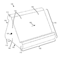
FIG. 1 is a perspective drawing illustrating one embodiment of a media support;
FIG. 2 is a side view drawing illustrating one embodiment of a media support;
FIG. 3 is a perspective drawing illustrating one alternate embodiment of a media support; and
FIG. 4 is a perspective drawing illustrating one embodiment of media disposed on a media support.
DETAILED DESCRIPTION
Reference throughout this specification to “one embodiment,” “an embodiment,” or similar language means that a particular feature, structure, or characteristic described in connection with the embodiment is included in at least one embodiment. Thus, appearances of the phrases “in one embodiment,” “in an embodiment,” and similar language throughout this specification may, but do not necessarily, all refer to the same embodiment, but mean “one or more but not all embodiments” unless expressly specified otherwise. The terms “including,” “comprising,” “having,” and variations thereof mean “including but not limited to” unless expressly specified otherwise. An enumerated listing of items does not imply that any or all of the items are mutually exclusive and/or mutually inclusive, unless expressly specified otherwise. The terms “a,” “an,” and “the” also refer to “one or more” unless expressly specified otherwise.
Furthermore, the described features, advantages, and characteristics of the embodiments may be combined in any suitable manner. One skilled in the relevant art will recognize that the embodiments may be practiced without one or more of the specific features or advantages of a particular embodiment. In other instances, additional features and advantages may be recognized in certain embodiments that may not be present in all embodiments.
The description of elements in each figure may refer to elements of proceeding figures. Like numbers refer to like elements in all figures, including alternate embodiments of like elements.
FIG. 1 is a perspective drawing illustrating one embodiment of a media support 100. The media support 100 may position media at one of three varied and carefully chosen angles for viewing by a user. The media may be handheld media. In addition, the media may be an electronic reader, a tablet computer, a video display, a magazine, a book, or the like. Because the media may be handheld, it is often viewed while the user is sitting at a table with the media on the table, while the user is sitting with the media disposed in the user's lap, or while the user is lying down.
During extended periods of viewing, it may be comfortable for the user to prop up the media to reduce hand and arm fatigue. Unfortunately, the use of traditional pillows may position the media at a less than advantageous angle. In addition, during extended viewing periods, the user may shift position, resulting in a need for a support with a different viewing angle. For example, a user may shift from reading while sitting on a couch to reading while lying on the couch.
The embodiments described herein provide support for multiple viewing angles. The angles are carefully chosen to support the media on a table for a sitting user, in the lap of a sitting user, and on a lying user. As a result, the media support 100 provides a comfortable support at an appropriate angle for the most common viewing positions.
In the depicted embodiment, the media support 100 includes three support sides 155. Each support side 155 comprises a support back 105 and a support edge 110. The support sides 155 may be disposed about a central axis 125. The media support 100 may have a latitudinal length 150. The latitudinal length 150 may be in the range of 6 to 50 centimeters (cm). In a certain embodiment, the latitudinal length 150 is in the range of 9 to 25 cm. In one embodiment, the latitudinal length 150 is 15 cm.
In one embodiment, the latitudinal length 150 of an edge support 110 may be different from the latitudinal length 150 of the corresponding side support 155. The edge support latitudinal length 150 may be in the range of 2 to 10 cm. In a certain embodiment, the edge support latitudinal length 150 is in the range of 6 to 8 cm. In one embodiment, the edge support latitudinal length 150 is 7 cm.
The side supports 155 may be arranged to provide three different viewing angles 160 for three different user positions. Each viewing angle 160 is orthogonal to a support back 105. The arrangement of the side supports 155 are disclosed in greater detail in FIG. 2.
In one embodiment, each back support 105 and each edge support 110 is a surface 175 of a solid. The solid media support 100 may have one or more ends 165. Each back support 105 and each edge support 110 may be in physical communication with two ends 165 of a solid interior.
The solid media support 100 may be a pillow. The solid interior may be foam. The foam may have an Indentation Force Deflection (IFD) of in the range of 15-30 kilograms at 25% indentation. In one embodiment, the surface 175 of the solid may be a fabric. Each back support 105, each edge support 110, and each end 165 may a surface 175 of the solid interior. The surface 175 of the solid interior may be a pillow is covered in fabric. In one embodiment, the fabric is ultra-suede.
A user may place the media support 100 on a table, in the user's lap, or on the user while lying down. The semi-rigid pillow feel of the media support 100 comfortably contacts the user while providing firm support for the media. The user may further rotate the media support 100 to select a back support 105 with a comfortable viewing angle 160. The user may place media on the edge support 110. The edge support 110 holds the media with the back of the media against the back support 105. As a result, the media may be viewed at the viewing angle 160.
FIG. 2 is a side view drawing illustrating one embodiment of a media support 100. The support backs 105 and the support edges 110 of the three support sides 155 are shown about an end 165. A top of each back support 105 is in physical communication with an adjacent edge support 110 about the central axis 125. A plane of a first back support 105 a may be at a first plane angle 120 a in a range of 50 to 60 degrees to a second virtual plane 130 b between the top of a second back support 105 b counterclockwise to the first back support 105 a and an outer edge of a second edge support 110 b counterclockwise to the first back support 105 a. In addition, a plane of the second back support 105 b may be at a second plane angle 120 b in a range of 55 to 65 degrees to a third virtual plane 130 c between the top of a third back support 105 c counterclockwise to the second back support 105 b and an outer edge of a third edge support 110 c counterclockwise to the second back support 110 b. A plane of a third back support 105 c may be at a third plane angle 120 c in a range of 50 to 75 degrees to a first virtual plane 130 a between the top of the first back support 105 a counterclockwise to the third back support 105 c and an outer edge of the first edge support 110 a counterclockwise to the third back support 105 c.
In one embodiment, the first back support 105 a has a longitudinal length 115 a in the range of 12 to 26 cm, the second back support 105 b has a longitudinal length 115 b in the range of 9 to 21 cm, and the third back support 105 c has a longitudinal length 115 c in the range of 10 to 22 cm. In a certain embodiment, the first longitudinal length 115 a is 19 cm, the first plane angle 120 a is 60 degrees, the second longitudinal length 115 b is 15 cm, the second plane angle 120 b is 68 degrees, the third longitudinal length 115 c is 17 cm, and the third plane angle 120 c is 52 degrees.
The arrangement of the longitudinal lengths 115 and the plane angles 120 generate three distinct viewing angles 160. In one embodiment, the first viewing angle 120 a may be 36 degrees, the second viewing angle 120 b may be 74 degrees, and the third viewing angle 120C may be 49 degrees.
In one embodiment, each edge support 110 forms an edge angle 140 with an adjacent back support 105. The edge angle 140 may be in the range of 85 to 120 degrees. The edge angle 140 may be 90 degrees. Each edge support 110 may have an edge support width 135. The edge support width 135 may be in the range of 1 to 5 cm. In a certain embodiment, the edge support width 135 is 2 cm.
FIG. 3 is a perspective drawing illustrating one alternate embodiment of a media support 100. In the depicted embodiment, each back support 105 and each edge support 110 is a surface 180 of a frame. Each end 165 may also be a surface 180 of a frame. The frame may include a molded mashed, a fabric mash, a wire mesh, or the like. In the depicted embodiment, the media support 100 includes ends 165. Alternatively, there may be no ends 165 on the media support 100.
FIG. 4 is a perspective drawing illustrating one embodiment of media 170 disposed on the media support 100. A bottom edge of the media 170 is disposed in the edge support 110 while the back of the media 170 is disposed against a back support 105.
The embodiments arrange three support sides 155 to generate three distinct viewing angles 160. Each viewing angle 160 is chosen for a specific viewing orientation. The first viewing angle 160 a may be employed when the media support 100 and the media is disposed in the user's lap. The second viewing angle 160 b may be used when the media support 100 and the media is disposed on a table and the user is sitting upright. In addition, the 3rd viewing angle 160 c may be used when the user is lying down and the media support 100 is disposed on the user.
When the user changes position, the media support 100 may be quickly rotated to provide a different viewing angle 160. As a result, the media support 100 is quickly deployed to provide the appropriate viewing angle 160. In addition, the comfort of the user is greatly enhanced as the media may be viewed at the appropriate viewing angle 160 without the user holding the media.
The media support 100 has been marketed as the “Flipy Tablet Pillow” since 2013 at a retail price of $49.98. Because of the media support's unique properties, it has enjoyed significant commercial success, with 800 units sold in 2013, 2,233 units in 2014, 925 units in 2015 and 997 units year-to-date in 2016.
Embodiments may be practiced in other specific forms. The described embodiments are to be considered in all respects only as illustrative and not restrictive. The scope of the invention is, therefore, indicated by the appended claims rather than by the foregoing description. All changes which come within the meaning and range of equivalency of the claims are to be embraced within their scope.

Claims (10)

What is claimed is:
1. An apparatus comprising:
three support sides, each support side comprising a back support and an edge support, wherein a top of each back support is in physical communication with an adjacent edge support clockwise about a central axis and each back support and each edge support is in physical communication with two ends of a solid interior, each edge support comprises an edge support width of 2 centimeters (cm) with an edge angle of 90 degrees to an adjacent back support, a face of each edge support width oriented clockwise about the central axis, a plane of a first back support is at a first plane angle of 60 degrees to a second virtual plane between the top of a second back support counterclockwise to the first back support and an outer edge of a second edge support counterclockwise to the first back support, a plane of the second back support is at a second plane angle of 80 degrees to a third virtual plane between the top of a third back support counterclockwise to the second back support and an outer edge of a third edge support counterclockwise to the second back support, a plane of a third back support is at a third plane angle of 40 degrees to a first virtual plane between the top of the first back support counterclockwise to the third back support and an outer edge of the first edge support counterclockwise to the third back support, and wherein each back support, each edge support, and each end is a surface of the solid interior, the solid interior is a pillow covered in fabric, a first viewing angle of the first back support is 36 degrees, a second viewing angle of the second back support is 74 degrees, and a third viewing angle of the third back support is 49 degrees.
2. The apparatus of claim 1, wherein the first back support has a longitudinal length in the range of 12 to 26 centimeters (cm), the second back support has a longitudinal length in the range of 9 to 21 cm, and the third back support has a longitudinal length in the range of 10 to 22 cm.
3. The apparatus of claim 2, wherein the first longitudinal length is 19 cm, the first plane angle is 60 degrees, the second longitudinal length is 15 cm, the second plane angle is 68 degrees, the third longitudinal length is 17 cm, and the third plane angle is 52 degrees.
4. The apparatus of claim 1, wherein each back support has a latitudinal length in the range of 9 to 25 cm.
5. The apparatus of claim 4, wherein each back support has a latitudinal length of 15 cm.
6. The apparatus of claim 1, wherein each edge support has a latitudinal length in the range of 2 to 10 cm.
7. The apparatus of claim 6, wherein each edge support has a latitudinal length of 7 cm.
8. The apparatus of claim 1, wherein each edge support has an edge support width in the range of 1 to 5 centimeters (cm).
9. The apparatus of claim 1, wherein a plane of each edge support forms an edge angle in the range of 85 to 120 degrees with an adjacent back support.
10. The apparatus of claim 9, wherein the edge angle is 90 degrees.
US15/192,737 2013-10-28 2016-06-24 Multiple viewing angle media support Ceased US9642454B2 (en)

Priority Applications (2)

Application Number Priority Date Filing Date Title
US15/192,737 US9642454B2 (en) 2013-10-28 2016-06-24 Multiple viewing angle media support
US16/262,797 USRE48479E1 (en) 2013-10-28 2019-01-30 Multiple viewing angle media support

Applications Claiming Priority (3)

Application Number Priority Date Filing Date Title
US201361896540P 2013-10-28 2013-10-28
US14/518,443 US20150115124A1 (en) 2013-10-28 2014-10-20 Multiple viewing angle media support
US15/192,737 US9642454B2 (en) 2013-10-28 2016-06-24 Multiple viewing angle media support

Related Parent Applications (1)

Application Number Title Priority Date Filing Date
US14/518,443 Continuation-In-Part US20150115124A1 (en) 2013-10-28 2014-10-20 Multiple viewing angle media support

Related Child Applications (1)

Application Number Title Priority Date Filing Date
US16/262,797 Reissue USRE48479E1 (en) 2013-10-28 2019-01-30 Multiple viewing angle media support

Publications (2)

Publication Number Publication Date
US20160302568A1 US20160302568A1 (en) 2016-10-20
US9642454B2 true US9642454B2 (en) 2017-05-09

Family

ID=57128148

Family Applications (1)

Application Number Title Priority Date Filing Date
US15/192,737 Ceased US9642454B2 (en) 2013-10-28 2016-06-24 Multiple viewing angle media support

Country Status (1)

Country Link
US (1) US9642454B2 (en)

Cited By (8)

* Cited by examiner, † Cited by third party
Publication number Priority date Publication date Assignee Title
USD807432S1 (en) * 2016-02-04 2018-01-09 Thinking Gifts Company Limited Book holder
US9915393B2 (en) * 2015-11-10 2018-03-13 Evan Bingham Grove Mobile device support with finger clearance
USD857431S1 (en) * 2017-10-26 2019-08-27 Sasagawa Co., Ltd. Goods display tool
USD866547S1 (en) * 2018-05-01 2019-11-12 James Godman Stand for a portable computing device or smart phone
USD930075S1 (en) * 2020-03-17 2021-09-07 Oahwip B.V. Document holder
USD933076S1 (en) * 2019-12-10 2021-10-12 Millie Products LLC Cushioned support base for a tablet computer
USD939023S1 (en) * 2020-03-17 2021-12-21 Oahwip B.V. Document holder
USD983189S1 (en) * 2020-08-21 2023-04-11 Simon Pearce (US) Inc. Holder

Families Citing this family (2)

* Cited by examiner, † Cited by third party
Publication number Priority date Publication date Assignee Title
CN110051126A (en) * 2019-04-17 2019-07-26 快乐产品公司 A kind of multi-angle of view media support device
KR102308464B1 (en) * 2021-04-23 2021-10-01 고종택 Three dimensional type detachable teaching device for standing teaching material up wity adjustable angle

Citations (25)

* Cited by examiner, † Cited by third party
Publication number Priority date Publication date Assignee Title
US805895A (en) 1905-05-09 1905-11-28 Gertrude F Wedderburn Card-support for dummy hands.
US3364603A (en) 1966-07-27 1968-01-23 Charles G. Tate Jr. Nameplate
US4274616A (en) 1979-04-20 1981-06-23 Radtke Alfred G Book stand
US4541190A (en) 1984-01-25 1985-09-17 Harold M. Hodgkins Multifaced, foldable traffic display
US4593876A (en) 1983-11-09 1986-06-10 Odin Greiner Picture stand for several pictures
US4880327A (en) 1988-09-16 1989-11-14 Richard F. Sanabria Gravity lock bookstand and binder
US4991812A (en) 1989-09-28 1991-02-12 Patricia MacEwan Portable viewing stand
US5029797A (en) 1989-09-19 1991-07-09 Gregory N. Levorchick Playing card holder
USD320319S (en) 1984-07-23 1991-10-01 Brothers William H Portable lectern
US5365687A (en) 1990-07-20 1994-11-22 United States Tobacco Company Motor vehicle roof-top display frame assembly
US5413305A (en) 1993-07-29 1995-05-09 Joseph Leeb Enterprises, Inc. Lightweight collapsible book stand
USD365461S (en) 1994-10-07 1995-12-26 Falter Steven J Lap desk
US5582382A (en) 1995-06-30 1996-12-10 Pan-Yang; Pi-Ju Folding book stand
USD392474S (en) 1997-03-17 1998-03-24 Joseph Frasketi Book stand
US6196512B1 (en) 1999-08-11 2001-03-06 Ernesto M. Ure Book stand
US6270049B1 (en) 1999-05-07 2001-08-07 Douglas A. Olvey Tabletop easel with page retention
US20030001063A1 (en) 2001-07-02 2003-01-02 Patti Halpin Book holding device
US20030136036A1 (en) 2002-01-18 2003-07-24 Zubli Leslie A. Card device and method for making a card device
US6651367B1 (en) 2001-01-12 2003-11-25 Demetrio Barragan Emergency message sign device for vehicles
US6934084B2 (en) 2001-08-20 2005-08-23 Ranjana Pandya Thinner, lighter and lower aberration prisms for ophthalmic applications
USD640112S1 (en) 2004-05-20 2011-06-21 Smith Harry S Jig for mitering crown molding
US8038116B2 (en) 2009-11-23 2011-10-18 Lee Eunyoung Portable and collapsible bookstand
USD677669S1 (en) 2011-10-27 2013-03-12 Jiyu Liu Portable support for electronic devices
USD690308S1 (en) 2012-03-21 2013-09-24 Thomas J. McCoy Mouse pad platform
USD703216S1 (en) 2013-08-02 2014-04-22 Zvi Klepar Dual-positioning tablet pillow stand

Patent Citations (25)

* Cited by examiner, † Cited by third party
Publication number Priority date Publication date Assignee Title
US805895A (en) 1905-05-09 1905-11-28 Gertrude F Wedderburn Card-support for dummy hands.
US3364603A (en) 1966-07-27 1968-01-23 Charles G. Tate Jr. Nameplate
US4274616A (en) 1979-04-20 1981-06-23 Radtke Alfred G Book stand
US4593876A (en) 1983-11-09 1986-06-10 Odin Greiner Picture stand for several pictures
US4541190A (en) 1984-01-25 1985-09-17 Harold M. Hodgkins Multifaced, foldable traffic display
USD320319S (en) 1984-07-23 1991-10-01 Brothers William H Portable lectern
US4880327A (en) 1988-09-16 1989-11-14 Richard F. Sanabria Gravity lock bookstand and binder
US5029797A (en) 1989-09-19 1991-07-09 Gregory N. Levorchick Playing card holder
US4991812A (en) 1989-09-28 1991-02-12 Patricia MacEwan Portable viewing stand
US5365687A (en) 1990-07-20 1994-11-22 United States Tobacco Company Motor vehicle roof-top display frame assembly
US5413305A (en) 1993-07-29 1995-05-09 Joseph Leeb Enterprises, Inc. Lightweight collapsible book stand
USD365461S (en) 1994-10-07 1995-12-26 Falter Steven J Lap desk
US5582382A (en) 1995-06-30 1996-12-10 Pan-Yang; Pi-Ju Folding book stand
USD392474S (en) 1997-03-17 1998-03-24 Joseph Frasketi Book stand
US6270049B1 (en) 1999-05-07 2001-08-07 Douglas A. Olvey Tabletop easel with page retention
US6196512B1 (en) 1999-08-11 2001-03-06 Ernesto M. Ure Book stand
US6651367B1 (en) 2001-01-12 2003-11-25 Demetrio Barragan Emergency message sign device for vehicles
US20030001063A1 (en) 2001-07-02 2003-01-02 Patti Halpin Book holding device
US6934084B2 (en) 2001-08-20 2005-08-23 Ranjana Pandya Thinner, lighter and lower aberration prisms for ophthalmic applications
US20030136036A1 (en) 2002-01-18 2003-07-24 Zubli Leslie A. Card device and method for making a card device
USD640112S1 (en) 2004-05-20 2011-06-21 Smith Harry S Jig for mitering crown molding
US8038116B2 (en) 2009-11-23 2011-10-18 Lee Eunyoung Portable and collapsible bookstand
USD677669S1 (en) 2011-10-27 2013-03-12 Jiyu Liu Portable support for electronic devices
USD690308S1 (en) 2012-03-21 2013-09-24 Thomas J. McCoy Mouse pad platform
USD703216S1 (en) 2013-08-02 2014-04-22 Zvi Klepar Dual-positioning tablet pillow stand

Cited By (8)

* Cited by examiner, † Cited by third party
Publication number Priority date Publication date Assignee Title
US9915393B2 (en) * 2015-11-10 2018-03-13 Evan Bingham Grove Mobile device support with finger clearance
USD807432S1 (en) * 2016-02-04 2018-01-09 Thinking Gifts Company Limited Book holder
USD857431S1 (en) * 2017-10-26 2019-08-27 Sasagawa Co., Ltd. Goods display tool
USD866547S1 (en) * 2018-05-01 2019-11-12 James Godman Stand for a portable computing device or smart phone
USD933076S1 (en) * 2019-12-10 2021-10-12 Millie Products LLC Cushioned support base for a tablet computer
USD930075S1 (en) * 2020-03-17 2021-09-07 Oahwip B.V. Document holder
USD939023S1 (en) * 2020-03-17 2021-12-21 Oahwip B.V. Document holder
USD983189S1 (en) * 2020-08-21 2023-04-11 Simon Pearce (US) Inc. Holder

Also Published As

Publication number Publication date
US20160302568A1 (en) 2016-10-20

Similar Documents

Publication Publication Date Title
US9642454B2 (en) Multiple viewing angle media support
USRE48479E1 (en) Multiple viewing angle media support
US8757375B2 (en) Support for a tablet computer with a function of receiving bag
US8424831B2 (en) One-piece support stand
AU2019412048B2 (en) Support frame for mobile equipment and computer equipment
US20070205648A1 (en) Elastic assembly of chair cushion
US20110169316A1 (en) Portable Travel Headrest
US6347771B1 (en) Portable arm and mouse support for use with personal computers
US20150115124A1 (en) Multiple viewing angle media support
US20180363837A1 (en) Portable Display Station
CN103445497A (en) Dual-purpose iPad folding desk for use on beds
CN210809815U (en) Multi-view media supporting device
CN110051126A (en) A kind of multi-angle of view media support device
CN207639884U (en) A kind of Multifunctional bed table
CN210137353U (en) Foldable mobile phone support
CN204617425U (en) The cabinet that a kind of table surface height is adjustable
CN106974437A (en) A kind of Multifunctional bed table
KR200452668Y1 (en) Portable terminal support
CN204928952U (en) Folding cell phone stand
CN206738851U (en) A kind of Portable computer rack
CN207383895U (en) A kind of multifunctional small-size bookshelf
CN105686365A (en) Adjusting type reading rack
CN201691360U (en) Novel laptop computer support
JP3210875U (en) Booklet pillow
CN103653917A (en) Foldable back-rest chair for bed

Legal Events

Date Code Title Description
STCF Information on status: patent grant

Free format text: PATENTED CASE

AS Assignment

Owner name: HAPPY PRODUCTS, INC., OREGON

Free format text: ASSIGNMENT OF ASSIGNORS INTEREST;ASSIGNORS:CANNON, BRUCE;FASSETT, JULIETTE;REEL/FRAME:046872/0562

Effective date: 20180913

RF Reissue application filed

Effective date: 20190130

FEPP Fee payment procedure

Free format text: MAINTENANCE FEE REMINDER MAILED (ORIGINAL EVENT CODE: REM.); ENTITY STATUS OF PATENT OWNER: MICROENTITY

FEPP Fee payment procedure

Free format text: SURCHARGE FOR LATE PAYMENT, MICRO ENTITY (ORIGINAL EVENT CODE: M3554); ENTITY STATUS OF PATENT OWNER: MICROENTITY

MAFP Maintenance fee payment

Free format text: PAYMENT OF MAINTENANCE FEE, 4TH YEAR, MICRO ENTITY (ORIGINAL EVENT CODE: M3551); ENTITY STATUS OF PATENT OWNER: MICROENTITY

Year of fee payment: 4