US9632535B2 - Docking sleeve with electrical adapter - Google Patents
Docking sleeve with electrical adapter Download PDFInfo
- Publication number
- US9632535B2 US9632535B2 US14/941,389 US201514941389A US9632535B2 US 9632535 B2 US9632535 B2 US 9632535B2 US 201514941389 A US201514941389 A US 201514941389A US 9632535 B2 US9632535 B2 US 9632535B2
- Authority
- US
- United States
- Prior art keywords
- shell
- electronic device
- skin
- adapter
- contactor
- Prior art date
- Legal status (The legal status is an assumption and is not a legal conclusion. Google has not performed a legal analysis and makes no representation as to the accuracy of the status listed.)
- Active
Links
Images


Classifications
-
- G—PHYSICS
- G06—COMPUTING; CALCULATING OR COUNTING
- G06F—ELECTRIC DIGITAL DATA PROCESSING
- G06F1/00—Details not covered by groups G06F3/00 - G06F13/00 and G06F21/00
- G06F1/16—Constructional details or arrangements
- G06F1/1613—Constructional details or arrangements for portable computers
- G06F1/1632—External expansion units, e.g. docking stations
-
- G—PHYSICS
- G06—COMPUTING; CALCULATING OR COUNTING
- G06F—ELECTRIC DIGITAL DATA PROCESSING
- G06F1/00—Details not covered by groups G06F3/00 - G06F13/00 and G06F21/00
- G06F1/16—Constructional details or arrangements
- G06F1/1613—Constructional details or arrangements for portable computers
- G06F1/1615—Constructional details or arrangements for portable computers with several enclosures having relative motions, each enclosure supporting at least one I/O or computing function
- G06F1/1616—Constructional details or arrangements for portable computers with several enclosures having relative motions, each enclosure supporting at least one I/O or computing function with folding flat displays, e.g. laptop computers or notebooks having a clamshell configuration, with body parts pivoting to an open position around an axis parallel to the plane they define in closed position
-
- G—PHYSICS
- G06—COMPUTING; CALCULATING OR COUNTING
- G06F—ELECTRIC DIGITAL DATA PROCESSING
- G06F1/00—Details not covered by groups G06F3/00 - G06F13/00 and G06F21/00
- G06F1/16—Constructional details or arrangements
- G06F1/1613—Constructional details or arrangements for portable computers
- G06F1/1633—Constructional details or arrangements of portable computers not specific to the type of enclosures covered by groups G06F1/1615 - G06F1/1626
- G06F1/1656—Details related to functional adaptations of the enclosure, e.g. to provide protection against EMI, shock, water, or to host detachable peripherals like a mouse or removable expansions units like PCMCIA cards, or to provide access to internal components for maintenance or to removable storage supports like CDs or DVDs, or to mechanically mount accessories
-
- G—PHYSICS
- G06—COMPUTING; CALCULATING OR COUNTING
- G06F—ELECTRIC DIGITAL DATA PROCESSING
- G06F1/00—Details not covered by groups G06F3/00 - G06F13/00 and G06F21/00
- G06F1/16—Constructional details or arrangements
- G06F1/18—Packaging or power distribution
- G06F1/181—Enclosures
-
- H—ELECTRICITY
- H01—ELECTRIC ELEMENTS
- H01R—ELECTRICALLY-CONDUCTIVE CONNECTIONS; STRUCTURAL ASSOCIATIONS OF A PLURALITY OF MUTUALLY-INSULATED ELECTRICAL CONNECTING ELEMENTS; COUPLING DEVICES; CURRENT COLLECTORS
- H01R13/00—Details of coupling devices of the kinds covered by groups H01R12/70 or H01R24/00 - H01R33/00
- H01R13/62—Means for facilitating engagement or disengagement of coupling parts or for holding them in engagement
- H01R13/6205—Two-part coupling devices held in engagement by a magnet
-
- H—ELECTRICITY
- H01—ELECTRIC ELEMENTS
- H01R—ELECTRICALLY-CONDUCTIVE CONNECTIONS; STRUCTURAL ASSOCIATIONS OF A PLURALITY OF MUTUALLY-INSULATED ELECTRICAL CONNECTING ELEMENTS; COUPLING DEVICES; CURRENT COLLECTORS
- H01R13/00—Details of coupling devices of the kinds covered by groups H01R12/70 or H01R24/00 - H01R33/00
- H01R13/62—Means for facilitating engagement or disengagement of coupling parts or for holding them in engagement
- H01R13/629—Additional means for facilitating engagement or disengagement of coupling parts, e.g. aligning or guiding means, levers, gas pressure electrical locking indicators, manufacturing tolerances
-
- H—ELECTRICITY
- H01—ELECTRIC ELEMENTS
- H01R—ELECTRICALLY-CONDUCTIVE CONNECTIONS; STRUCTURAL ASSOCIATIONS OF A PLURALITY OF MUTUALLY-INSULATED ELECTRICAL CONNECTING ELEMENTS; COUPLING DEVICES; CURRENT COLLECTORS
- H01R24/00—Two-part coupling devices, or either of their cooperating parts, characterised by their overall structure
- H01R24/66—Two-part coupling devices, or either of their cooperating parts, characterised by their overall structure with pins, blades or analogous contacts and secured to apparatus or structure, e.g. to a wall
- H01R24/68—Two-part coupling devices, or either of their cooperating parts, characterised by their overall structure with pins, blades or analogous contacts and secured to apparatus or structure, e.g. to a wall mounted on directly pluggable apparatus
-
- H—ELECTRICITY
- H01—ELECTRIC ELEMENTS
- H01R—ELECTRICALLY-CONDUCTIVE CONNECTIONS; STRUCTURAL ASSOCIATIONS OF A PLURALITY OF MUTUALLY-INSULATED ELECTRICAL CONNECTING ELEMENTS; COUPLING DEVICES; CURRENT COLLECTORS
- H01R2105/00—Three poles
Abstract
A docking sleeve having an elastomeric protective cover, or skin, adapted for partially enveloping a portable electronic device, such as a smartphone or tablet or another portable electronic device of the prior art having a port for a docking connector. The protective cover is a 5 sheath molded of a suitable elastic or flexibly resilient elastomer in a size and shape to fit over and closely conform to the particular portable electronic device so that the cover fits the device like a surgical glove. An adapter is provided for electrically connecting to the female input/output socket of the particular electronic device, including a male plug having a plurality of electrical connectors 10 extended internally of the sheath and arranged for mating with the female input/output socket of the device, and a plurality of contacts electrically coupled to different ones of the plurality of electrical connectors and exposed externally of the sheath.
Description
This patent application is a continuation of U.S. patent application Ser. No. 14/667,564 filed Mar. 24, 2015, now U.S. Pat. No. 9,195,279, which is a continuation of PCT Application No. PCT/US2015/017131 filed Feb. 23, 2015 which is a continuation-in-part of co-pending U.S. patent application Ser. No. 14/222,320 filed Mar. 21, 2014 which claims priority to U.S. Provision Patent Application Ser. No. 61/943,986, filed Feb. 24, 2014, and this patent application also claims priority to U.S. Provisional Patent Application No. 62/040,037 filed Aug. 21, 2014, all of which are incorporated herein by reference.
The present invention relates to a cover for protecting a portable electronic device, and in particular to a flexible cover having an electrical adapter for coupling the device to a docking station.
Protective covers, or ‘skins’, are generally well-known for protecting a portable electronic device, such as a smartphone, or tablet or another portable electronic device. Such skins are typically somewhat flexible which allows them to be wrapped around to partially envelop a device.
However, known protective covers, or ‘skins’, are limited in their ability to provide efficient and reliable usage of such portable electronic devices.
The present invention is a cover for protecting a portable electronic device that overcomes limitations of the prior art for efficient and reliable usage of such portable electronic devices.
Known protective covers, or ‘skins’ are generally simply shell coverings that are somewhat flexible which allows them to be fitted around a device to partially envelop it. These skins are useful only for protecting the device. Until the present invention, there has not existed a skin that provides an integral electrical adapter that allows the device to be easily docked into a cradle to provide pass-through power and other external wired functions such as audio, USB, etc.
A problem with smartphones, tablets and some other portable electronic devices is they do not include a built-in docking connector as do rugged laptop computers. Typically smartphones and tablets have female input/output (I/O) sockets that allow for mating of specific electrical cables with appropriate plugs, but are not designed for docking into the docking connector of a docking cradle.
The present invention is a novel low-cost flexible cover or skin that includes a structurally integral electrical adapter that mates with the I/O socket of the target device, and also includes contacts that easily mate with typical docking cradles.
According to one aspect of the invention, the protective cover includes a flexible protective shell that is complimentary in shape to the target electronic device, wherein the shell at least partially covers side faces and one front or back face of the device and extends around a peripheral edge of the opposite face.
Most docking cradles either use some sort of biasing pogo pin or biasing leaf spring contact in the docking connector. Therefore, the protective cover of the invention includes an electrical adapter that is structurally integral with the shell and positioned adjacent to the female input/output socket of the electronic device, wherein the adapter is formed with a male plug that is projected interior of the shell in an arrangement for mating with the female input/output socket of the device, and a contactor formed with a plurality of contacts that are electrically coupled to the plug and exposed to an exterior of the shell in a position for mating with the docking connector when the device is docked into the cradle while remaining in the protective cover.
Other aspects of the invention are detailed herein.
The foregoing aspects and many of the attendant advantages of this invention will become more readily appreciated as the same becomes better understood by reference to the following detailed description, when taken in conjunction with the accompanying drawings, wherein:
As required, a detailed illustrative embodiment of the present protective enclosure is disclosed herein. However, techniques, systems and operating structures in accordance with the present protective enclosure may be embodied in a wide variety of forms and modes, some of which may be quite different from those in the disclosed embodiment. Consequently, the specific structural and functional details disclosed herein are merely representative, yet in that regard, they are deemed to afford the best embodiment for purposes of disclosure and to provide a basis for the claims herein which define the scope of the present protective enclosure. The following presents a detailed description of an illustrative embodiment (as well as some alternative embodiments) of the present protective enclosure.
In the Figures, like numerals indicate like elements.
A smartphone, or smart phone, is a mobile phone with more advanced computing capability and connectivity than basic feature phones. Early smartphones typically combined the features of a mobile phone with those of another popular consumer device, such as a personal digital assistant (PDA), a media player, a digital camera, and/or a GPS navigation unit. Modern smartphones include all of those features plus usually include the additional features of a touch-screen computer, including web browsing, Wi-Fi, and 3rd-party apps and accessories. The most popular smartphones today are powered by Google's Android and Apple's iOS mobile operating systems. See, e.g., Wikipedia, The Free Encyclopedia.
A tablet computer, or simply tablet, is a mobile computer with display, circuitry and battery in a single unit. Tablets are equipped with sensors, including cameras, microphone, accelerometer and touch-screen, with linger or stylus gestures replacing computer mouse and keyboard. Tablets may include physical buttons, e.g., to control basic features such as speaker volume and power and ports for network communications and to charge the battery. An on-screen, pop-up virtual keyboard is usually used for typing. Tablets are typically larger than smart phones or personal digital assistants at 7 inches (18 cm) or larger, measured diagonally. One example of a tablet is the iPad tablet computer from Apple. See. e.g., Wikipedia, The Free Encyclopedia.
Hybrid tablets having detachable keyboards have been sold since the mid-1990s. Convertible touch-screen notebook computers have an integrated keyboard that can be hidden by a swivel or slide joint. Booklet tablets have dual-touch-screens and can be used as a notebook by displaying a virtual keyboard on one of the displays. See, e.g., Wikipedia, The Free Encyclopedia.
As disclosed herein, an electrical adapter is part of protective cover 100, the adapter includes a male plug having a plurality of electrical connectors extending into a cavity formed by protective cover 100 in an arrangement for mating with a female input/output socket of the smartphone or tablet or other portable electronic device 1, and a contactor having a plurality of electrical contacts that are positioned adjacent to an exterior of protective cover 100 and are electrically coupled to one or more of the connectors of the plug.
Accordingly, when the electronic device 1 is received within the cavity of flexible protective cover 100, the plurality of connectors of the male plug are mated with the female socket of the device 1. Thereafter, the female input/output socket is electrically accessed through the plurality of contacts of the contactor that are exterior of protective cover 100.
Optionally, contactor 120 of adapter 114 is further recessed in outer surface 124 of unitary protective shell 102. By example and without limitation, an optional dam 132 is formed in outer surface 124 of unitary protective shell 102, and adapter contactor 120 is further recessed within dam 132. Electrical contacts 122 of contactor 120 are protected from damage by being recessed within dam 132 or otherwise within outer surface 124 of unitary protective shell 102.
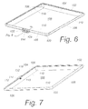
Here, an interior window opening 134 is formed in flexible center panel 104 of flexible protective shell 102 opposite from mouth opening 112 and in a position over touch-sensitive screen display 25 of portable electronic device 1 for operation of electronic device 1.
An integral interior window panel 138 is positioned in flexible center panel 104 within window opening 134, and is retained in protective shell 102 by continuous integral lip 136 surrounding opening 134. For example, as more clearly illustrated in FIG. 14 , a peripheral edge 140 of interior window panel 138 is welded, adhered, bonded or otherwise joined to integral lip 136 of window opening 134. Optionally, an substantially watertight joint 142 is formed between interior window panel 138 and integral lip 136 of window opening 134. According to one embodiment, interior window panel 138 is overmolded into integral lip 136 of window opening 134 for joining to integral lip 136 and forming watertight joint 142 therebetween.
Integral interior window panel 138 is formed of a substantially optically transparent membrane for use with portable electronic device 1 having a pressure-sensitive touch screen 25, whereby operation of electronic device 1 via touch-sensitive screen 25 is accomplished through intervening window panel 138.
Optionally, interior window panel 138 is formed of a hard, inelastic and noncompressible material. For example, the plastic sheet component forming interior window panel 138 is optionally a noncompressible sheet of relatively hard and substantially visually transparent material, including but not limited to polyethylene terephthalate (PET) or another suitable substantially visually transparent material. According to one embodiment, the plastic sheet component forming interior window panel 138 is optionally a noncompressible sheet of relatively hard and substantially visually transparent polyvinyl chloride (PVC) material. As disclosed herein, interior window panel 138 formed of PET or PVC or other hard, noncompressible and inelastic plastic sheet material similarly permits tactile stimulation of the touch-sensitive screen display 25 of portable electronic device 1.
Alternatively, optionally either the entirety of protective shell 102, or only interior window panel 138, is formed of an optically transparent flexible elastomer membrane which is either clear, or may be tinted with color, such as pink or blue as may be aesthetically pleasing. In other embodiments, the protective shell 102 is opaque or translucent and may be any color or pattern. In such embodiments, the portable electronic device 1 is disposed within the protective cover 100 with its display visible through the mouth opening 112.
Optionally, the optically transparent elastomer of protective shell 102 or only interior window panel 138 is a dielectric material having static dissipative properties, such as an effective dielectric constant on the order of about 4.5. For example, the elastomer includes a quantity of powdered metal, mixed-metal oxides, polymers, or is coated with a static dissipative coating. Optionally, the optically transparent elastomer of protective shell 102 or only interior window panel 138 is polarized to reduce glare. Accordingly, protective cover 100 is optionally utilized with portable electronic device 1 having a pressure-sensitive touch screen that permits inputting data of and operating the device 1 by application of light pressure by the user as is generally well-known.
Portable electronic device 1 is illustrated as being inserted through second mouth opening 112 into cavity 108 of flexible protective shell 102 with touch-sensitive screen 25 being positioned in contact with interior window panel 138 of opposing center panel 104, whereby the flexibility of the elastomeric material permits application of pressure to touch-sensitive screen 25 for inputting data and operating the electronic device 1 in general. As disclosed herein, interior window panel 138 of center panel 104 is structured as a thin flexible membrane in a position that corresponds to touch-sensitive screen 25 of device 1. By example and without limitation, window area of flexible center panel 104 is expected to be about 0.05 to 0.06 inch thick, or another thickness suitable for permitting touch-sensitive screen 25 to respond to pressure exerted by the user for inputting data and operating the electronic device 1 in general. Integral interior window panel 138 of center panel 104 covers pressure-sensitive touch screen 25 of electronic device 1 to protect it from scratching, denting, and other external abrasions. Side skirt 106 and portions of protective shell 102 surrounding interior window panel 138 of center panel 104 may be thicker for providing protection from bumps and scrapes.
When mouth opening 112 is formed through side skirt 106 adjacent to one side 144 of protective shell 102, electrical adapter 114 is positioned in side skirt 106 at a second side 148 opposite from side 144. With mouth opening 112 and electrical adapter 114 thus located at opposite sides 144 and 148, respectively, of protective shell 102, male plug 116 of electrical adapter 114 is extended into cavity 108 of shell 102 in a position to be received into and mechanically and electrically mated with the female input/output socket 27 of device 1 when portable electronic device 1 is received within cavity 108 through side mouth opening 112. Accordingly, in practice portable electronic device 1 is inserted (arrow 150) into protective shell 102 through side mouth opening 112 and into interior cavity 108 until the female input/output socket 27 is mechanically mated with male plug 116 of electrical adapter 114, whereupon female input/output socket 27 is simultaneously electrically mated with electrical adapter 114. Portable electronic device 1 is removed from protective shell 102 in reverse order along the insertion direction (arrow 150).
Optionally, contactor body 128 b of adapter contactor 120 is recessed in outer surface 124 of unitary protective shell 102. By example and without limitation, optional dam 132 is formed in outer surface 124 of unitary protective shell 102, and adapter contactor 120 is further recessed within dam 132. Electrical contacts 122 of contactor 120 are protected from damage by being recessed within dam 132 or otherwise within outer surface 124 of unitary protective shell 102.
Optionally, side 102 a and/or side 102 b of protective shell 102 are optionally adapted to receive plurality of electrical conductors 126 within skirt 106 of protective shell 102. For example, portions of side 102 a and/or side 102 b of protective shell 102 are optionally thickened to accommodate additional volume of plurality of electrical conductors 126 within skirt 106.
As illustrated here, contactor body 128 b of adapter contactor 120 is recessed in outer surface 124 of side skirt 106 of unitary protective shell 102. By example and without limitation, optional dam 132 is formed in outer surface 124 of unitary protective shell 102, and adapter contactor 120 is further recessed within dam 132. Electrical contacts 122 of contactor 120 are protected from damage by being recessed within dam 132 or otherwise within outer surface 124 of unitary protective shell 102.
As disclosed herein, dam 132 is a locator formed in outer surface 124 that cooperates with docking cradle 5 as a positioning interface for positively positioning unitary protective shell 102 relative to docking connector 3 for promoting mating therebetween.
As disclosed in each of FIG. 11 and FIG. 13 , positioning interface dam 132 operates as a locator on outer surface 124 of unitary protective shell 102 that cooperates with a socket receiver of docking cradle 5 for positively positioning contactor 120 with docking connector 3 for mechanical and electrical coupling therebetween. For example, dam 132 is projected or extended from outer surface 124 of unitary protective shell 102, with adapter contactor 120 and electrical contacts 122 thereof being recessed within recess of locator dam 132, as illustrated for example in FIG. 8 . As illustrated in each of FIG. 3 , FIG. 4 and FIG. 5 , clocking connector 3 is recessed within a socket receiver that is recessed within interior surface of base receiver 9 of clocking cradle tray 7. Socket receiver thus cooperates with locator dam 132 for positively positioning unitary protective shell 102 relative to docking connector 3 in receiver 9 of docking cradle tray 7 for promoting mating therebetween, as illustrated herein.
Docking cradle tray 7 optionally includes a mechanism for securing to an external mounting surface S. Accordingly, by example and without limitation, the docking cradle tray 7 is pierced by one or more fastener clearance holes 172 each sized to pass therethrough a mechanical fastener appropriate for attaching docking cradle tray 7 to an external mounting surface such as an intermediate mounting device, as discussed herein. Fastener clearance holes 172 optionally include coincidental annular depressions or recesses 174, either countersinks or counter bores, for recessing the head of a threaded fastener passing therethrough below either of both of upper operational surface 156 and recessed socket floor 168.
Alternatively, one or more fastener is optionally integrated with tray 7 of clocking cradle 5. For example, the heads of two pair of threaded studs are embedded in the molded structure of docking cradle tray 7 with their threaded shafts projecting out of lower interface surface 158 so as to be inserted through matching apertures in an external mounting surface and secured with nuts. In such instance fastener clearance holes 172 are filled with the fasteners' threaded shafts. Furthermore, recessed socket floor 168, and surrounding socket rim 164 as well as peripheral transition wall 170 therebetween are optionally left completely unbroken, and docking cradle tray 7 thus presents a substantially solid and unbroken surface. Other mechanisms for attaching to external mounting surface S, such as adhesives or pressure sensitive adhesive tapes and films, are also contemplated and may be included or substituted without deviating from the scope and intent of the present invention.
Optionally, female nest 157 of docking cradle tray 7 is formed with one or more male rotational control features 176 that are configured to maintain a rotational orientation between unitary protective shell 102 of protective cover 100 and clocking cradle tray 7. By example and without limitation, male rotational control features 176 are configured as shallow intrusions into recessed socket receiver 166 by straight or curved (shown) portions of peripheral transition wall 170 between recessed socket floor 168 and surrounding socket rim 164. Alternatively, peripheral transition wall 170 of socket receiver 166 is configured with any generally square or rectangular, oval, kidney, rectangular or other regular or irregular shapes, whereby rotational control features 176 are inherent in socket receiver 166 as provided by such non-round shapes.
According to one embodiment, shell 102 of protective cover 100 is retained in tray 7 of docking cradle 5 under the weight of portable electronic device 1 in shell 102, i.e., by force of gravity. Positioning interface dam 132 of shell 102 cooperates with docking cradle 5 by nesting into socket receiver 166 recessed in docking cradle tray 7.
Alternatively, one or more permanent magnets 178 are provided between shell 102 of protective cover 100 and tray 7 of docking cradle 5 for securing protective cover 100 in docking cradle 5. By example and without limitation, one or more permanent magnets 178 are disposed within a magnet retention structure 180 that is adjacent to either recessed floor 168 of socket receiver 166, or surrounding socket rim 164 (shown). When present, each permanent magnet 178 is, by example and without limitation, a thin round or disk-shape. Although the disk shape is convenient, other magnet shapes are equivalent and maybe substituted. Magnet 178 is optionally of the well-known rare-earth variety. Rare-earth magnets are very powerful in proportion to size and are therefore useful in practice of the present invention. However, other known and presently unknown magnets that are sufficiently powerful for practice of the invention are equivalent and may be substituted.
By example and without limitation, magnet retention structure 180 is embodied as a plurality of cavities that individually position each magnet 178 in close proximity to either recessed floor 168 of socket receiver 166, or surrounding socket rim 164 of female nest 157. According to one embodiment of the invention, each cavity of magnet retention structure 180 minimizes the distance between magnet 178 and socket's recessed floor 168, or surrounding socket rim 164. Attenuation of magnetic fields generated by magnets 178 is thereby minimized, and the magnetic field generated remains sufficiently powerful to ensure retention of most handheld electronic and other small devices by magnetic attraction to cooperating clocking cradle 5.
According to one embodiment, cavities of magnet retention structure 180 are sized to match magnets 178, either as a slip fit or a compression fit such that each magnet 178 is inserted under at least light pressure and as much as a press fit.
As disclosed herein, docking connector 3 includes plurality of biasing electrical contacts 11 configured, for example, as spring-loaded pogo pins that are electrically coupled to electrical leads 13 in wire or cable 15. Typically, clocking connector 3 includes a minimum number of at least two biasing electrical contacts 11, but is not limited to having greater numbers of contacts 11.
When peripheral transition wall 170 of female socket receiver 166 is inclined between socket floor 168 and surrounding socket rim 164, complementary male locator dam 132 optionally includes a exterior peripheral transition wall 184 extended between contactor surface 182 and external surface 152 of flexible center panel 104 and formed with a substantially matching incline. Accordingly, inclined complementary male locator dam 132 nests in incline of recessed socket receiver 166 of female nest 157.
When socket receiver 166 of female nest 157 is configured with one or more male rotational control features 176, complementary male locator dam 132 is configured with one or more matching rotational control features 186. For example, when rotational control features 176 of female socket receiver 166 are configured as male peripheral protrusions of transition wall 170 into interior of socket 166 between recessed socket floor 168 and surrounding socket rim 164, rotational control features 186 are configured as matching female indents or intrusions into periphery of complementary locator dam 132 that are positioned and sized to mate with male rotational control features 176 in socket transition wall 170.
Alternatively, matching male and female rotational control features 176 and 186 are optionally reversed between female socket receiver 166 and complementary locator dam 132 such that female rotational control features 176 are presented in complementary locator dam 132 of shell 102 as male peripheral protrusions of transition wall 184, and matching female rotational control features 186 are presented as complementary female indents or intrusions into periphery of transition wall 170 into rim 164 surrounding female socket receiver 166.
Thus, as disclosed here, male positioning interface 132 includes a combination of both offset projection contactor surface 182 with recessed female rotational control features 186 formed in its periphery and which are, for example, coplanar with surrounding peripheral rim formed by external surface 152 of flexible center panel which contacts rim 164 surrounding socket receiver 166 when seated in female nest 157 of docking cradle tray 7. Recessed female rotational control features 186 of male positioning interface 132 engage male rotational control features 176 of docking cradle tray 7 in female nest 157, whereby shell 102 is rotationally oriented relative to base receiver 9 of tray 7. Accordingly, complementary locator dam 132 on external surface 152 of protective shell 102 nests with female socket receiver 166 in base receiver 9 of docking cradle tray 7, while mating male and female rotational control features 176, 186 control rotation of protective shell 102 relative to base receiver 9 of tray 7.
When tray 7 of docking cradle 5 includes optional magnets 178 adjacent to recessed floor 168 or surrounding rim 164 of socket receiver 166, as shown in FIG. 24 , center panel 104 of protective shell 102 is provided with a magnetically permeable member 188 embodied as a thin sheet or plate of a ferrous or other highly magnetically permeable ferromagnetic material, such as iron, nickel, cobalt or another ferromagnetic material or alloy. For example, magnetically permeable member 188 is embedded in center panel 104 of protective shell 102 in a complementary position for attraction by magnets 178. Magnets 178 and magnetically attractive member 188 thus form a magnetic attraction couple operable between shell 102 of protective cover 100 and tray 7 of docking cradle 5 for securing protective cover 100 in docking cradle 5.
When electrical contacts 122 of contactor 120 are configured as the plurality of concentric contact rings, cooperating male and female rotational control features 176 and 186 are optionally eliminated because contact rings 122 normally mate with different pogo pin contacts 11 in any orientation of shell 102 relative to docking cradle tray 7 regardless of rotation (FIG. 25 , arrows 190) of positioning interface dam 132 in female socket receiver 166. However, cooperating male and female rotational control features 176 and 186 may be present for providing relative rotational relationship between protective cover 100 and docking cradle 3, if desired.
According to one embodiment, electrical contacts 122 of contactor 120 engage biasing electrical contacts 11 of base receiver 9 of docking cradle 3 under the weight of shell 102 with electronic device 1 therein, i.e., by force of gravity, as disclosed herein.
Alternatively, when optional magnets 178 are present, magnetic attraction between magnets 178 and magnetically permeable member 188 operates to secure shell 102 of protective cover 100 in nested engagement with tray 7 of docking cradle 5 and engage electrical contacts 122 of contactor 120 with biasing electrical contacts 11 of base receiver 9 of docking cradle 5.
When protective cover, or skin, 100 is retained in tray 7 of docking cradle 3 under force of gravity, simply lifting shell 102 will release protective cover 100 for removal from cradle 3.
Alternatively, when optional magnets 178 are present, magnetic attraction between magnets 178 and magnetically permeable member 188 operates to secure shell 102 of protective cover 100 in nested engagement with tray 7 of docking cradle 5. However, simply rotating shell 102 (FIG. 25 , arrows 190) causes positioning interface dam 132 to be rotated until female rotational control features 186 interfere with matching male rotational control features 176 of tray 7 of docking cradle 5. Such interference causes shell 102 to separate from base receiver 9 and attenuate the magnetic attraction, whereby protective cover 100 is released for removal from cradle 3.
Additionally, one or more permanent magnets 178 mounted in complementary male nesting appendage 159 of protective cover 100. For example, magnets 178 are embedded in center panel 104 of protective shell 102 for cooperating with magnetically permeable members 188 for magnetically securing protective cover 100 in docking cradle 5.
Thus, as disclosed here, male positioning interface 132 includes a combination of both contactor surface recessed in floor 168 of socket receiver 166 with projected rotational control features 176 formed in its periphery and which are, for example, coplanar with surrounding peripheral contact rim 164 surrounding socket floor 168. Contact rim 164 engages operational surface 156 of docking cradle tray 7 when female nest 157 is seated over complementary male nesting appendage 159 of docking cradle tray 7. Projected rotational control features 176 of female positioning interface 132 engage recessed rotational control features 186 of docking cradle tray 7 in male nesting appendage 159, whereby shell 102 is rotationally oriented relative to base receiver 9 of tray 7.
Optionally, shell 102 of protective cover 100 is retained in tray 7 of docking cradle 5 under weight, i.e., by force of gravity, as disclosed herein. Alternatively, optional magnets 178 and magnetically permeable member 188, when present, may be provided in either of docking cradle tray 7 or protective shell 102, as disclosed herein. As illustrated here by example and without limitation, magnets 178 are provided in magnet retention structure 180 that is adjacent to either recessed floor 168 of socket receiver 166, or surrounding socket rim 164 (shown).
Substantially planar contactor surface 182 is offset or projected from upper operational surface 156 of docking cradle tray 7 and is configured with any generally round, square or rectangular, oval, kidney, rectangular or other regular or irregular shape and sized to fit snugly within recessed socket receiver 166 of female locator dam 132 of nest 157 on protective shell 102. Thus, upper operational surface 156 of docking cradle tray 7 engages peripheral support rim 164 of locator dam 132 in protective shell 102 when projected contactor surface 182 of complementary male nesting appendage 159 nests in recessed socket receiver 166 in female locator dam 132 of nest 157.
Thus, as disclosed here, complementary male nesting appendage 159 of docking cradle tray 7 includes a combination of both contactor surface 182 projected from upper operational surface 156 of base receiver 9 with female rotational control features 186 recessed in its periphery and which are, for example, coplanar with surrounding peripheral contact rim formed as operational surface 156. Operational surface 156 engages contact rim 164 of peripheral surface 164 forming a support rim surrounding socket receiver 166 of locator dam 132 that is projected from external surface 152 of flexible center panel 104 of shell 102 (shown in FIG. 30 ) when female nest 157 is seated over complementary male nesting appendage 159 of docking cradle tray 7. Projected male rotational control features 176 of female positioning interface 132 engage recessed female rotational control features 186 of docking cradle tray 7 in male nesting appendage 159, whereby shell 102 is rotationally oriented relative to base receiver 9 of tray 7.
As disclosed herein, docking connector 3 includes plurality of biasing electrical contacts 11 configured, for example, as spring-loaded pogo pins that are electrically coupled to electrical leads 13 in wire or cable 15.
Docking cradle tray 7 is optionally pierced by fastener clearance holes 172 for attaching docking cradle tray 7 to an external mounting surface, as discussed herein. Fastener clearance holes 172 optionally include coincidental annular depressions or recesses 174, either countersinks or counter bores, as discussed herein, for recessing the head of a threaded fastener passing therethrough below projected contactor surface 182 of complementary male nesting appendage 159. As further disclosed herein, other mechanisms for attaching to external mounting surface S, such as adhesives or pressure sensitive adhesive tapes and films, are also contemplated and may be included or substituted without deviating from the scope and intent of the present invention.
Exterior peripheral transition wall 184 of complementary projected male nesting appendage 159 is optionally inclined for cooperatively nesting in incline of recessed socket receiver 166 for positively positioning unitary protective shell 102 relative to docking connector 3 in receiver 9 of docking cradle tray 7.
When locator dam 132 of protective shell 102 is formed with male rotational control features 176, tray 7 of docking cradle 5 may be thrilled with matching female rotational control features 186 that mate with male rotational control features 176 and cooperate for controlling rotational orientation between protective shell 102 and docking cradle tray 7.
Alternatively, matching male and female rotational control features 176 and 186 are optionally reversed between female socket receiver 166 of locator dam 132, forming female nest 157 on protective shell 102, and complementary male nesting appendage 159 of docking cradle tray 7 such that rotational control features 186 are presented as female indents or intrusions into periphery of transition wall 170 into rim 164 surrounding female socket receiver 166 of locator dam 132, and matching rotational control features 176 are presented as complementary male peripheral protrusions of transition wall 184.
When protective cover 100 is secured by the weight of the portable electronic device 1 in shell 102, i.e., by force of gravity, as disclosed herein, tray 7 of docking cradle 5 is expected to be presented with complementary male nesting appendage 159 of base receiver 9 oriented generally upright for receiving female nest 157 of protective shell 102 thereonto. Alternatively, one or more permanent magnets 178 and magnetically permeable members 188 are disposed in complementary locations for magnetic attraction between shell 102 of protective cover 100 and tray 7 of docking cradle 5. For example, when optional magnets 178 and magnetically permeable member 188 are present, as illustrated here, rotation of docking cradle tray 7 is possible with electronic device 1 in protective cover 100 being releasably magnetically mounted thereon. Depending upon the strength of magnetic attraction as a function of selected magnets 178 and magnetically permeable member 188, tray 7 of docking cradle 5 can be tilted or rotated to a greater extreme, even to inverted with docking cradle tray 7 being upside-down, with electronic device 1 secured therein by magnetic attraction between protective cover 100 and docking cradle tray 7 sufficiently that electrical contacts 122 of shell contactor 120 remain mechanically and electrically coupled to electrical contacts 11 of docking connector 3 sufficiently for operation of electronic device 1.
As illustrated by example and without limitation, one or more magnetically permeable members 188 each embodied as a thin sheet or plate of a ferrous or other highly magnetically permeable ferromagnetic material, such as iron, nickel, cobalt or another ferromagnetic material or alloy, as disclosed herein, are embedded in either recessed floor 168 of female socket receiver 166, or surrounding socket rim 164 (shown) of locator dam 132 on protective shell 102. Additionally, one or more permanent magnets 178 mounted in complementary male nesting appendage 159 of protective cover 100. For example, magnets 178 are embedded in center panel 104 of protective shell 102 for cooperating with magnetically permeable members 188 for magnetically securing protective cover 100 in docking cradle 5.
Alternatively, relative locations of magnets 178 and magnetically permeable member 188 are optionally inverted, as disclosed herein, wherein one or more magnets 178 are disposed within a magnet retention structure 180 in female nest 157 of locator dam 132 on protective shell 102, and one or more magnetically permeable members 188 are disposed in a complementary location in operational surface 156 of tray 7 adjacent to male nesting appendage 159 of base receiver 9.
As disclosed herein, interior transition wall 170 of socket receiver 166 cooperates with exterior peripheral transition wall 184 of complementary projected male nesting appendage 159 for positively positioning unitary protective shell 102 relative to docking connector 3 in receiver 9 of docking cradle tray 7.
Furthermore, when locator dam 132 of protective shell 102 is formed with rotational control features 176, tray 7 of docking cradle 5 may be formed with complementary rotational control features 186 that mate with rotational control features 176 and cooperate therewith for controlling rotational orientation between protective shell 102 and docking cradle tray 7.
Alternatively, magnets 178 are in base receiver 9 of docking cradle tray 7, and cooperating magnetically permeable members 188 are flanking electrical contacts 122 of contactor 120 in locator dam 132 exterior of protective shell 102.
In at least some embodiments, different covers 100 can be provided for different types of portable electronic devices 1, but the arrangement of electrical contacts 122 is the same so that a variety of different portable electronic devices 1 (including devices from different manufacturers) can be coupled to the same docking cradle 5 using an appropriate cover 100. It will be understood that the internal arrangement of electrical conductors 126 (which connect the electrical contacts 122 of the adapter 114 to the electrical connectors 118 of the male plug 116) of the different covers 100 may be different depending on the type of portable electronic device 1 that fits in the cover 100. Moreover, in at least some embodiments, one or more of the electrical contacts 122 may not be coupled to a corresponding electrical contact 118 of the adapter 114, particularly if there is not a corresponding contact in the portable electrical device 1 for which the cover 100 is designed.
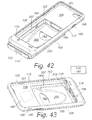
A cover for a portable electronic device can also include an additional pocket for a peripheral device. FIGS. 42-46 illustrate an embodiment of a cover 100 that can receive a portable electronic device 1 and a peripheral device 50. Examples of peripheral devices include, but are not limited to, a printer, a scanner, a card reader, a magnetic strip reader, a RFID reader, a NFC reader, a speaker, a battery, a camera, a light, a keyboard, a human interface device (e.g., a mouse, trackball, or the like), a medical device (e.g., a thermometer, glucose sensor, blood pressure monitor, imager, or any other suitable medical device), or any other suitable peripheral device. The cover 100 may be designed for a specific type of peripheral device or may accommodate multiple types of peripheral devices. In addition, although the illustrated embodiment permits inclusion of a single peripheral device in the cover, it will be understood that other embodiments can permit inclusion of multiple (e.g., two, three, four, or more) peripheral devices in one or more peripheral pockets in the cover.
The cover 100 includes a shell 102 with a center panel 104, a side skirt 106, a lip 110, a mouth opening 112, and an interior cavity 108 to receive the portable electronic device 1. In addition, the cover 100 includes a peripheral cavity 208 that forms a peripheral pocket for receiving the peripheral device 50. The peripheral cavity 208 can be formed using the center panel 104 and optionally part of the side skirt 106 or any other portion of the cover 100. The peripheral cavity 208 defines a device surface 205 and one or more side surfaces 207. In the illustrated embodiment, the peripheral cavity 208 and interior cavity 108 are contiguous and the peripheral device 50 can be inserted into the peripheral cavity 208 through the mouth opening 112 and interior cavity 108, as illustrated in FIG. 44 . The portable electronic device 1 can then be inserted into the interior cavity 110 through the mouth opening, as illustrated in FIG. 45 . In other embodiments, the cover 100 may include a peripheral opening (not shown) through which the peripheral may be inserted into the peripheral cavity 208. In such embodiments, the peripheral cavity 208 may be contiguous with the interior cavity 108 or the peripheral cavity and interior cavity can separated by a wall of the cover 100.
In addition to the male plug 116, the cover 100 includes a peripheral plug 216, illustrated in FIG. 43 . The peripheral plug 216 fits into the input/output socket of the peripheral device 50. The peripheral plug 216 may be designed for a particular peripheral device or may be suitable for multiple different devices. For example, the peripheral plug 216 (or the male plug 116 or both) can be a USB or microUSB plug designed to fit into a USB or microUSB port, respectively, in the peripheral device 50.
The peripheral plug 216 includes one or more electrical connectors 218 that connect to contacts within the peripheral device 50. The one or more electrical connectors 218 are coupled to the electrical contacts 122 of the adapter 114 of the cover 100 using conductors (not shown) that extend through the cover. This arrangement can be used to provide power to the peripheral device 50 via the adapter 114 and one or more electrical connectors 218. In at least some embodiments, the adapter 114 and associated conductors can be arranged so that the peripheral device 50 provides power, data, or both to the portable electronic device 1 through the adapter. For example, the adapter 114 may couple an electrical connector 218 of the peripheral plug 216 and an electrical connector 118 of the male plug 116 to the same electrical contact 122 of the adapter so that the peripheral device 50 can provide power or data to the portable electronic device 1 through the adapter. It will be understood that there are other mechanisms for sharing data between the peripheral device 50 and the portable electronic device 1 such as Bluetooth, NFC, and the like.
The cover 100 can include one or more openings 194 through the cover into the peripheral cavity 218. These openings 194 can allow access to components of the peripheral device 50 such as, for example, a jack, a scanner, a printer, a sensor, or the like. Similarly, the cover 100 can include one or more openings 196 into the interior cavity 118 to allow access to components of the portable electronic device. For example, the openings 196 can allow access to a camera, a headphone jack, a switch, a speaker, a microphone, or the like of the portable electronic device 1. In at least some embodiments, the placement, number, and size of the openings 196 of the cover are specifically arranged based on the type of portable electronic device for which the cover 100 is designed. In some embodiments, the cover 100 can include soft buttons 198 formed in the cover (for example, in the side skirt 106) at positions that can coincide with buttons on the portable electronic device 1. The soft buttons 196 can be, for example, part of the material of the cover with a surrounding indentation to identify placement of the soft button and facilitate actuation of the soft button. The soft buttons 196 are configured and arranged so that actuation of the soft button also actuates the underlying button of the portable electronic device 1. Such soft buttons 196 may coincide with power, volume, and other buttons on the portable electronic device 1. Any of the covers described herein can include one or more openings 196, one or more soft buttons 198, or any combination thereof.
Any of the covers 100 described herein can also include a tag element 199 disposed within or on the cover, as illustrated in FIG. 43 . The tag element 199 can be, for example, a RFID tag or a NFC tag that can be used to identify the cover or device disposed within the cover. The tag element 199 can be molded into the cover 100 or may be disposed on an interior or exterior surface of the cover. In at least some embodiments, the tag element 199 can be associated with a fob 197 or other tag query device that a user can carry and which can be used to wirelessly query the tag element 199 to determine if the cover 100 is within a range of the fob or other tag query device. The fob 197 can be activated by the user to assist in finding the cover or associated portable electronic device. Alternatively or additionally, the fob 197 may include an audible alarm, vibratory alarm, or both that can be automatically activated when the fob exceeds a threshold distance from the cover 100 to warn the user that the cover 100 and associated portable electronic device are left behind (for example, left on the docking cradle). In some embodiments, the user may select whether the fob 197 provides an audible alarm, a vibratory alarm, or both. In some embodiments, the user may program the threshold distance.
In some embodiments, the docking cradle can include electronic components for providing power, data, or other signals to the portable electronic device from the cradle. In other embodiments, the docking cradle is a “pass-through” device where the docking cradle is simply an intermediary between the portable electronic device and another device, such as a charger, computer, other portable electronic device, or the like. In these embodiments, the cable exiting the docking cradle can be coupled to this other device and, at least in some instances, the docking cradle merely transmits signals between the electronic contacts of the docking cradle and the cable.
While the preferred and additional alternative embodiments of the invention have been illustrated and described, it will be appreciated that various changes can be made therein without departing from the spirit and scope of the invention. Therefore, it will be appreciated that various changes can be made therein without departing from the spirit and scope of the invention. Accordingly, the inventor makes the following claims.
Claims (20)
1. A protective skin for an electronic device, the protective skin comprising:
a flexible protective shell comprising a panel and a skirt surrounding the panel, wherein the panel and skirt form an interior cavity therebetween, and the skirt forming a mouth opening that communicates with the interior cavity, wherein the interior cavity is configured and arranged to receive an electronic device entirely within the interior cavity; and
an adapter fixedly positioned in the shell, the adapter comprising a male plug comprising a plurality of connectors extending into the interior cavity of the shell in an arrangement for mating with a female socket of the electronic device, a contactor comprising a flat surface opposite the male plug and an arrangement of a plurality of contacts with each of the contacts exposed at the flat surface and at least partially flush with the flat surface and electrically coupled to one or more of the connectors of the male plug, and a male positioning interface disposed on the shell and defining a rim around the contactor of the adapter and extending away from the skirt to the flat surface of the contactor to guide proper mating of the contactor of the adapter to an external connector.
2. The skin of claim 1 , wherein the rim defines an asymmetric shape.
3. The skin of claim 2 , wherein the asymmetric shape comprises a straight side and a curved side opposite the straight side.
4. The skin of claim 1 , wherein the positioning interface extends solely between the contactor and an adjacent portion of the shell.
5. The skin of claim 1 , wherein the shell is a one-piece, elastomeric shell.
6. The skin of claim 5 , wherein the skin is configured and arranged to completely cover a back surface and side surfaces of the electronic device and to extend over a portion of a front surface of the electronic device.
7. The skin of claim 1 , wherein the shell further defines a peripheral cavity, wherein the peripheral cavity is configured and arranged to receive a peripheral device, the skin further comprising a peripheral plug extending into the peripheral cavity in an arrangement for mating with a female socket of the peripheral device, the peripheral plug comprising at least one connector that is electrically coupled to one or more of the contacts of the adapter.
8. The skin of claim 7 , wherein the peripheral cavity is adjacent to the interior cavity of the shell so that the peripheral device can be inserted into the peripheral cavity through the mouth and the interior cavity.
9. The skin of claim 7 , wherein one of the at least one connector of the peripheral plug and one of the connectors of the male plug are both coupled to a same one of the contacts of the adapter.
10. The skin of claim 1 , further comprising a tag element disposed within or on the shell and configured and arranged to a tag query device to indicate presence of the skin.
11. The skin of claim 1 , wherein the positioning interface comprises a magnetic coupling element resident in the shell adjacent to the contactor, wherein the magnetic coupling element comprises one of a magnetic material or a magnetically attractive material.
12. The skin of claim 1 , wherein the adapter further comprises a plurality of conductors coupling the connectors of the male plug to the contacts of the contactor, wherein each conductor couples one of the connectors to a corresponding one of the contacts, wherein a spatial arrangement of the connectors of the male plug is different than a spatial arrangement of the corresponding ones of the contacts.
13. A docking system, comprising:
the skin of claim 1 ; and
a docking cradle comprising a tray configured to receive the skin and a docking connector comprising a plurality of contacts positioned to connect with one or more of the plurality of contacts of the contactor.
14. The docking system of claim 13 , wherein the docking cradle further comprises a female base receiver configured to mate with the male positioning interface of the skin.
15. A protective skin for an electronic device, the protective skin comprising:
a flexible protective shell comprising a panel and a skirt surrounding the panel, wherein the panel and skirt form an interior cavity of the shell, and the skirt forming a mouth opening that communicates with the interior cavity, wherein the interior cavity is configured and arranged to receive an electronic device with a portion of the shell at least partially covering a back surface and extending over a peripheral edge of a front surface of the electronic device to capture the electronic device within the interior cavity of the shell; and
an adapter fixedly positioned in the shell, the adapter comprising a male plug comprising a plurality of connectors extending into the interior cavity of the shell in an arrangement for mating with a female socket of the electronic device, a contactor comprising a plurality of contacts adjacent to an exterior of the shell and electrically coupled to one or more of the connectors of the male plug, and a positioning interface disposed on the shell and defining a rim around the contactor of the adapter to guide proper mating of the contactor of the adapter to an external connector.
16. The skin of claim 15 , wherein the skin is configured and arranged to completely cover the back surface and a plurality of side surfaces of the electronic device.
17. The skin of claim 15 , wherein the shell is a one-piece, elastomeric shell.
18. The skin of claim 15 , wherein the adapter further comprises a plurality of conductors coupling the connectors of the male plug to the contacts of the contactor, wherein each conductor couples one of the connectors to a corresponding one of the contacts, wherein a spatial arrangement of the connectors of the male plug is different than a spatial arrangement of the corresponding ones of the contacts.
19. A docking system, comprising:
the skin of claim 15 ; and
a docking cradle comprising a tray configured to receive the skin and a docking connector comprising a plurality of contacts positioned to connect with one or more of the plurality of contacts of the contactor.
20. The skin of claim 15 , wherein the skirt is resilient and configured and arranged, upon application of a force, to permit widening of the mouth for insertion of the electronic device into the interior cavity and then, upon removal of the force, to narrow the mouth to capture and hold the electronic device within the interior cavity of the shell.
Priority Applications (2)
| Application Number | Priority Date | Filing Date | Title |
|---|---|---|---|
| US14/941,389 US9632535B2 (en) | 2014-02-24 | 2015-11-13 | Docking sleeve with electrical adapter |
| US15/495,796 US10054984B2 (en) | 2014-02-24 | 2017-04-24 | Docking sleeve with electrical adapter |
Applications Claiming Priority (6)
| Application Number | Priority Date | Filing Date | Title |
|---|---|---|---|
| US201461943986P | 2014-02-24 | 2014-02-24 | |
| US14/222,320 US9331444B2 (en) | 2014-02-24 | 2014-03-21 | Docking sleeve with electrical adapter |
| US201462040037P | 2014-08-21 | 2014-08-21 | |
| PCT/US2015/017131 WO2015127376A1 (en) | 2014-02-24 | 2015-02-23 | Docking sleeve with electrical adapter |
| US14/667,564 US9195279B2 (en) | 2014-02-24 | 2015-03-24 | Docking sleeve with electrical adapter |
| US14/941,389 US9632535B2 (en) | 2014-02-24 | 2015-11-13 | Docking sleeve with electrical adapter |
Related Parent Applications (1)
| Application Number | Title | Priority Date | Filing Date |
|---|---|---|---|
| US14/667,564 Continuation US9195279B2 (en) | 2014-02-24 | 2015-03-24 | Docking sleeve with electrical adapter |
Related Child Applications (1)
| Application Number | Title | Priority Date | Filing Date |
|---|---|---|---|
| US15/495,796 Continuation US10054984B2 (en) | 2014-02-24 | 2017-04-24 | Docking sleeve with electrical adapter |
Publications (2)
| Publication Number | Publication Date |
|---|---|
| US20160070300A1 US20160070300A1 (en) | 2016-03-10 |
| US9632535B2 true US9632535B2 (en) | 2017-04-25 |
Family
ID=53882151
Family Applications (3)
| Application Number | Title | Priority Date | Filing Date |
|---|---|---|---|
| US14/667,564 Active US9195279B2 (en) | 2014-02-24 | 2015-03-24 | Docking sleeve with electrical adapter |
| US14/941,389 Active US9632535B2 (en) | 2014-02-24 | 2015-11-13 | Docking sleeve with electrical adapter |
| US15/495,796 Active US10054984B2 (en) | 2014-02-24 | 2017-04-24 | Docking sleeve with electrical adapter |
Family Applications Before (1)
| Application Number | Title | Priority Date | Filing Date |
|---|---|---|---|
| US14/667,564 Active US9195279B2 (en) | 2014-02-24 | 2015-03-24 | Docking sleeve with electrical adapter |
Family Applications After (1)
| Application Number | Title | Priority Date | Filing Date |
|---|---|---|---|
| US15/495,796 Active US10054984B2 (en) | 2014-02-24 | 2017-04-24 | Docking sleeve with electrical adapter |
Country Status (1)
| Country | Link |
|---|---|
| US (3) | US9195279B2 (en) |
Cited By (7)
| Publication number | Priority date | Publication date | Assignee | Title |
|---|---|---|---|---|
| US10050397B1 (en) * | 2017-06-26 | 2018-08-14 | Daniel Hetzroni | Mount for a touch-screen device |
| US10312631B1 (en) * | 2018-02-20 | 2019-06-04 | The Boeing Company | Detachable communications connector for vehicle stores and method therefor |
| US10483688B2 (en) * | 2017-06-14 | 2019-11-19 | Microsoft Technology Licensing, Llc | Magnetically activated latch mechanism |
| WO2021216444A1 (en) | 2020-04-20 | 2021-10-28 | National Products, Inc. | Cradles and cases for mobile devices incorporating guide elements or modular components and methods of making and using |
| WO2021216430A2 (en) | 2020-04-20 | 2021-10-28 | National Products, Inc. | Cases for mobile devices with a flexible covering and rigid frame or with two different connector arrangements and methods of making and using |
| WO2021252296A2 (en) | 2020-06-10 | 2021-12-16 | National Products, Inc. | Cases for mobile devices having a window to facilitate heat dissipation and methods of making and using |
| US11270824B2 (en) | 2018-01-12 | 2022-03-08 | Scooch, LLC | Ferromagnetic accessories for a handheld device |
Families Citing this family (31)
| Publication number | Priority date | Publication date | Assignee | Title |
|---|---|---|---|---|
| US10050658B2 (en) | 2014-02-24 | 2018-08-14 | National Products, Inc. | Docking sleeve with electrical adapter |
| CN104834399B (en) * | 2015-04-15 | 2018-06-22 | 业成光电(深圳)有限公司 | Touch-control display module |
| US9698851B2 (en) * | 2015-05-27 | 2017-07-04 | Heartware, Inc. | Electronic device holder |
| EP3345078B1 (en) * | 2015-09-04 | 2024-04-24 | Apple Inc. | Flexible keyboard accessory for a portable electronic device |
| US9778705B2 (en) | 2015-09-04 | 2017-10-03 | Apple Inc. | Electronic device with moveable contacts at an exterior surface |
| US10579097B2 (en) * | 2015-09-04 | 2020-03-03 | Apple Inc. | Electronic device with contacts flush with housing |
| US9948018B2 (en) | 2015-09-08 | 2018-04-17 | Apple Inc. | Low-profile power and data contacts |
| US9363904B1 (en) * | 2015-12-18 | 2016-06-07 | Nanoport Technology Inc. | Adapters for adapting an electronic device to a modular electronic device system |
| TWI595859B (en) * | 2016-01-08 | 2017-08-21 | 豪展醫療科技股份有限公司 | Physiological status monitoring device |
| US9729187B1 (en) * | 2016-02-01 | 2017-08-08 | Otter Products, Llc | Case with electrical multiplexing |
| KR20170100324A (en) * | 2016-02-25 | 2017-09-04 | 엘지디스플레이 주식회사 | Ultra thin display device |
| KR102609515B1 (en) * | 2016-03-21 | 2023-12-04 | 삼성전자주식회사 | Connector apparatus and display apparatus having thereof |
| JP7010579B2 (en) * | 2016-03-23 | 2022-01-26 | 株式会社アスタリスク | Connection unit, information processing device |
| WO2018005345A1 (en) | 2016-06-27 | 2018-01-04 | National Products, Inc. | Slide dock and methods of making and using |
| US11832690B2 (en) * | 2017-01-17 | 2023-12-05 | II Richard P. Steinke | Snap and lock |
| US10274993B2 (en) * | 2017-04-30 | 2019-04-30 | Nathaniel Teator | Portable device docking station for privacy protection |
| US20180339433A1 (en) * | 2017-05-24 | 2018-11-29 | Jun He Technology Co., Ltd. | Security label and manufacturing method of the same |
| US20190082563A1 (en) * | 2017-09-11 | 2019-03-14 | Apple Inc. | Plate for magnetic shielding of an operational component in a portable electronic device |
| US10707627B2 (en) | 2017-09-29 | 2020-07-07 | Apple Inc. | Hybrid connector |
| US11552428B2 (en) | 2019-02-25 | 2023-01-10 | Juggernaut Defense, Llc | Systems and methods for a cable clip |
| TW202043969A (en) * | 2019-05-28 | 2020-12-01 | 和碩聯合科技股份有限公司 | Electronic device |
| US10678301B1 (en) * | 2019-08-01 | 2020-06-09 | Moxa Inc. | Assembled industrial tablet |
| US11489350B2 (en) | 2019-12-23 | 2022-11-01 | National Products, Inc. | Cradle for mobile devices with resilient guides and methods of making and using |
| CN113163045B (en) * | 2020-01-22 | 2023-08-04 | 华为技术有限公司 | Pressure detection structure and electronic equipment |
| US10812643B1 (en) * | 2020-05-04 | 2020-10-20 | National Products, Inc. | Cases for mobile devices incorporating a light within the case and methods of making and using |
| US11277506B2 (en) | 2020-05-26 | 2022-03-15 | National Products, Inc. | Cradles for mobile devices with one or more biasing tabs and methods of making and using |
| US11076032B1 (en) | 2020-05-26 | 2021-07-27 | National Products, Inc. | Cradles for mobile devices with a plunger lock and methods of making and using |
| CN112799468B (en) * | 2021-01-22 | 2021-10-08 | 江西络鑫科技有限公司 | Docking station with clamping mechanism |
| US11652326B2 (en) | 2021-04-30 | 2023-05-16 | National Products, Inc. | Dock with flexible locator pins and methods of making and using |
| US20240128996A1 (en) | 2022-10-13 | 2024-04-18 | National Products, Inc. | Remote repeater device for mobile device dock and methods of making and using |
| US11815224B1 (en) * | 2023-02-21 | 2023-11-14 | Brodit Ab | Quick connect electronic device mount with knob release |
Citations (128)
| Publication number | Priority date | Publication date | Assignee | Title |
|---|---|---|---|---|
| US809977A (en) | 1903-02-02 | 1906-01-16 | Arthur O'brien | Flexible pipe. |
| US1786459A (en) | 1926-07-30 | 1930-12-30 | Simons Burdick | Baby-bottle holder |
| US2495552A (en) | 1946-02-09 | 1950-01-24 | Schmitz Otto | Watertight watchcase |
| US2549917A (en) | 1949-06-04 | 1951-04-24 | Wallace C Milbrandt | Display cover device |
| US2565939A (en) | 1947-04-10 | 1951-08-28 | Roderic T Wriston | Lined waterproof container |
| US2612947A (en) | 1950-04-27 | 1952-10-07 | Albert S Jenks | Resiliently expansive window closure |
| US2717093A (en) | 1950-10-28 | 1955-09-06 | Skydyne Inc | Shipping case or the like |
| US2803368A (en) | 1954-12-06 | 1957-08-20 | Maurice P Koch | Thermal insulated carrying cases and sealing means for same |
| US3018525A (en) | 1960-05-05 | 1962-01-30 | Robert J Deisenroth | Glass run for windows |
| US3140883A (en) | 1962-10-23 | 1964-07-14 | Ralph L Anthony | Book cover |
| US3464579A (en) | 1967-06-01 | 1969-09-02 | Shell Oil Co | Water-tight plastic container |
| US3667648A (en) | 1970-07-06 | 1972-06-06 | Beatrice Foods Co | Slip out glass panel for cover member |
| US3885701A (en) | 1973-10-23 | 1975-05-27 | Environmental Container System | Valance molding for equipment cases |
| US3972459A (en) | 1975-04-14 | 1976-08-03 | Cooper Daniel A | Tape dispenser having snap lock core members |
| US3978830A (en) | 1975-01-13 | 1976-09-07 | Trw Inc. | Snap-on spring retainer lock |
| US4298204A (en) | 1980-01-21 | 1981-11-03 | Black & Decker Inc. | Seal |
| US4564880A (en) | 1984-03-14 | 1986-01-14 | Motorola, Inc. | Apparatus and method for protecting integrated circuits |
| US4607772A (en) | 1984-07-23 | 1986-08-26 | George Gates | Rifle carrier for motorcycle |
| US4828558A (en) | 1987-07-28 | 1989-05-09 | Kelman Charles D | Laminate optic with interior Fresnel lens |
| US4842174A (en) | 1987-04-07 | 1989-06-27 | Sheppard Mark E | Flexible mount for mobile apparatus |
| US4848319A (en) | 1985-09-09 | 1989-07-18 | Minnesota Mining And Manufacturing Company | Refracting solar energy concentrator and thin flexible Fresnel lens |
| US5002184A (en) | 1989-06-12 | 1991-03-26 | Grid Systems Corporation | Soft case protection for a hand held computer |
| US5096317A (en) | 1991-03-12 | 1992-03-17 | Phillippe Kerin L | Computer key cover apparatus |
| US5135189A (en) | 1991-08-16 | 1992-08-04 | Mansoor Ghazizadeh | Baby bottle holder |
| US5246133A (en) | 1991-09-16 | 1993-09-21 | Sealright Co., Inc. | Injection molded lid with window |
| US5272771A (en) | 1987-04-21 | 1993-12-28 | Smith & Nephew Plc | Gloves |
| US5295602A (en) | 1993-03-17 | 1994-03-22 | General Motors Corporation | Housing with snap latch closure |
| US5353934A (en) | 1992-08-06 | 1994-10-11 | Dai Nippon Printing Co., Ltd. | Substrate holding case |
| US5535274A (en) | 1991-10-19 | 1996-07-09 | Cellport Labs, Inc. | Universal connection for cellular telephone interface |
| US5584054A (en) | 1994-07-18 | 1996-12-10 | Motorola, Inc. | Communication device having a movable front cover for exposing a touch sensitive display |
| US5586002A (en) | 1992-06-24 | 1996-12-17 | John Notarianni | Protective case and interface housing containing computer devices and the like |
| US5641065A (en) | 1995-06-22 | 1997-06-24 | Paragon Group Of Plastics Companies, Inc. | Medical instrument soaking, transporting and storage container |
| US5646649A (en) | 1994-08-23 | 1997-07-08 | Mitsubishi Denki Kabushiki Kaisha | Portable information terminal |
| US5791506A (en) | 1996-07-02 | 1998-08-11 | Charles Chang | Sealing container which includes a two-part cap for displaying a cosmetic product |
| US5813096A (en) | 1996-01-26 | 1998-09-29 | Daimler-Benz Aerospace Airbus Gmbh | Snap fastener with a safety lock |
| US5842670A (en) | 1996-06-13 | 1998-12-01 | Nigoghosian; Gregory H. | Hair dryer support |
| US5845885A (en) | 1993-12-14 | 1998-12-08 | National Products, Inc. | Universally positionable mounting device |
| US5860550A (en) | 1994-08-04 | 1999-01-19 | Smithkline Beecham Corporation | Container with overlapping peripheral flanges |
| US5895018A (en) | 1997-05-14 | 1999-04-20 | Rielo; Ricardo G. | Magnetic support attachment |
| US5953795A (en) | 1997-07-22 | 1999-09-21 | Bauer; Irving | Magnetic snap lock |
| US5969057A (en) | 1996-04-26 | 1999-10-19 | Huels Silicone Gmbh | Adhesive RTV silicone rubber compounds |
| US5990874A (en) | 1996-08-02 | 1999-11-23 | Matsushita Electric Industrial Co., Ltd. | Protective cover for a portable apparatus touch panel |
| US5992807A (en) | 1996-06-27 | 1999-11-30 | Intec - Srl | Universal magnetic stand for cell phones |
| US6010005A (en) | 1998-12-30 | 2000-01-04 | Gemtron Corporation | Serving tray |
| US6009601A (en) | 1997-06-04 | 2000-01-04 | Kaufman; Eli | Magnetic snap lock |
| US6034505A (en) | 1997-05-20 | 2000-03-07 | Selfcharge Inc. | Rechargeable charging cradle and night light |
| US6032910A (en) | 1995-08-24 | 2000-03-07 | Richter; Herbert | Flexible support arm for supporting objects |
| US6035800A (en) | 1997-04-28 | 2000-03-14 | Clifford; Peter A. | Gunwale attachable dry box for small watercraft |
| US6043626A (en) | 1996-10-29 | 2000-03-28 | Ericsson Inc. | Auxiliary battery holder with multicharger functionality |
| US6068119A (en) | 1996-07-18 | 2000-05-30 | Testo Gmbh & Co. | Watertight protective device for holding a measuring or display device |
| US6149116A (en) | 1999-02-12 | 2000-11-21 | D.L. Telecom Co. Ltd. | Holder for mobile telephone |
| US6273773B1 (en) | 1999-09-03 | 2001-08-14 | Vincent A. Bourke | Scuba diver's marker buoy and dry box |
| US6276552B1 (en) | 1999-07-06 | 2001-08-21 | Steve Vervisch | Sealed container latch system |
| US6295198B1 (en) | 2000-03-07 | 2001-09-25 | Hewlett-Packard Company | Computer device |
| US6341218B1 (en) | 1999-12-06 | 2002-01-22 | Cellport Systems, Inc. | Supporting and connecting a portable phone |
| US6356053B1 (en) | 1999-09-22 | 2002-03-12 | Lucent Technologies Inc. | Charging mechanism for cordless telephone and other electrical devices |
| US6377825B1 (en) * | 2000-02-18 | 2002-04-23 | Cellport Systems, Inc. | Hands-free wireless communication in a vehicle |
| US6407860B1 (en) | 1998-12-02 | 2002-06-18 | Kuraray Co., Ltd. | Fresnel lens sheet |
| US6406758B1 (en) | 2000-07-25 | 2002-06-18 | 3M Innovative Properties Company | Method of applying a protective coating to a touch screen panel |
| US6572176B2 (en) | 2000-07-07 | 2003-06-03 | Donnelly Corporation | Vehicle window assembly |
| US6585212B2 (en) | 2001-08-20 | 2003-07-01 | Jeffrey D. Carnevali | Quick release electronics platform |
| US6588637B2 (en) | 2001-08-28 | 2003-07-08 | All Rite Products, Inc. | Holding device with alternating length gripping fins |
| US6614423B1 (en) | 2000-08-21 | 2003-09-02 | Symbol Technologies, Inc. | Touch-pad cover protecting against wear, spills and abuse |
| US6646864B2 (en) | 2001-11-19 | 2003-11-11 | Otter Products, Llc | Protective case for touch screen device |
| US6648376B2 (en) | 2002-03-29 | 2003-11-18 | Showertek, Inc. | Flexible sectioned arm with internal overbending-prevention sleeves |
| US6702604B1 (en) | 1999-08-23 | 2004-03-09 | Jerry Moscovitch | Universal quick connector apparatus for an LCD monitor |
| US20040108348A1 (en) | 2002-12-09 | 2004-06-10 | Barnes Ted A. | Accessory mount for vehicle control bodies |
| US6762585B2 (en) | 2001-10-03 | 2004-07-13 | Sheng Hsin Liao | Combinational charger apparatus |
| US6776422B1 (en) | 2002-06-26 | 2004-08-17 | William W. Toy | Slotted elastomeric O-rings |
| US6785566B1 (en) | 2002-02-04 | 2004-08-31 | Louis Irizarry | Cellular telephone case |
| US6785567B2 (en) | 2001-10-26 | 2004-08-31 | Kabushiki Kaisha Toshiba | Radio device holder including device locking member and tray having tray locking member |
| US6816713B2 (en) * | 2001-04-04 | 2004-11-09 | E-Lead Electronic Co., Ltd. | Switching and retaining device for use in cellular phones and peripheral communication equipment thereof |
| US6842171B2 (en) | 2001-06-20 | 2005-01-11 | 3M Innovative Properties Company | Touch panel having edge electrodes extending through a protective coating |
| US20050189354A1 (en) | 2002-05-09 | 2005-09-01 | Louise Heather | Container for a brushable coating composition |
| US6953126B2 (en) | 2001-10-31 | 2005-10-11 | Pelican Products, Inc. | Protective case |
| US6984680B2 (en) | 2003-04-15 | 2006-01-10 | Adherent Laboratories, Inc. | Low odor, light color hot pick-up adhesive |
| US7017243B2 (en) | 2003-08-07 | 2006-03-28 | Carnevali Jeffrey D | Secure interface cradle for pocket personal computer device |
| US7031148B1 (en) | 2005-08-04 | 2006-04-18 | Chia-Hao Lin | Notebook computer protector |
| US20060175766A1 (en) | 2005-01-28 | 2006-08-10 | Carnevali Jeffrey D | Dry box with sealed window |
| US7158376B2 (en) | 2001-11-19 | 2007-01-02 | Otter Products, Llc | Protective enclosure for an interactive flat-panel controlled device |
| US7180735B2 (en) | 2001-11-19 | 2007-02-20 | Otter Products, Llc | Protective enclosure and watertight adapter for an interactive flat-panel controlled device |
| US7230823B2 (en) | 2003-08-20 | 2007-06-12 | Otter Products, Llc | Protective membrane for touch screen device |
| US7248901B2 (en) | 2001-01-18 | 2007-07-24 | Andreas Peiker | Arrangement for handling a communication device |
| US7257429B2 (en) | 2005-05-13 | 2007-08-14 | Symbol Technologies, Inc. | Overheating and spill resistant mobile device docking cradle |
| US7283849B2 (en) | 2001-01-18 | 2007-10-16 | Andreas Peiker | Assembly comprising a mobile telephone |
| US7311526B2 (en) | 2005-09-26 | 2007-12-25 | Apple Inc. | Magnetic connector for electronic device |
| US7351066B2 (en) | 2005-09-26 | 2008-04-01 | Apple Computer, Inc. | Electromagnetic connector for electronic device |
| US7464814B2 (en) | 2005-01-28 | 2008-12-16 | Carnevali Jeffrey D | Dry box with movable protective cover |
| US7480138B2 (en) | 2005-06-30 | 2009-01-20 | Symbol Technologies, Inc. | Reconfigurable mobile device docking cradle |
| US7520389B2 (en) | 2004-05-24 | 2009-04-21 | Seagate Technologies, Llc | Package structure for soft mounting direct connect storage device |
| US7551458B2 (en) | 2005-05-24 | 2009-06-23 | Carnevali Jeffrey D | Secure universal mounting apparatus |
| US7594576B2 (en) | 2004-11-12 | 2009-09-29 | Hong Fu Jin Precision Industry (Shenzhen) Co., Ltd. | PDA carrying device |
| US7609512B2 (en) | 2001-11-19 | 2009-10-27 | Otter Products, Llc | Protective enclosure for electronic device |
| US7612997B1 (en) | 2008-11-17 | 2009-11-03 | Incase Designs Corp. | Portable electronic device case with battery |
| US20090314400A1 (en) | 2008-06-24 | 2009-12-24 | Keng-Yuan Liu | Protective Cover With Power Supply Unit For Portable Electronic Device |
| US7663879B2 (en) | 2001-11-19 | 2010-02-16 | Otter Products, Llc | Protective enclosure for personal digital assistant case having integrated back lighted keyboard |
| US7688580B2 (en) | 2001-11-19 | 2010-03-30 | Otter Products, Llc | Modular accessory for protective case enclosing touch screen device |
| US7812567B2 (en) | 2008-06-12 | 2010-10-12 | Wen Hong Shen | Battery charger stand set for motor vehicle |
| US7850032B2 (en) | 2005-01-28 | 2010-12-14 | Carnevali Jeffrey D | Sealed window for dry box |
| US7889489B2 (en) | 2001-11-19 | 2011-02-15 | Otter Products, Llc | Detachable pod assembly for protective case |
| US7907394B2 (en) | 2001-11-19 | 2011-03-15 | Otter Products, Llc | Protective enclosure for touch screen device |
| US8061516B2 (en) | 2007-08-16 | 2011-11-22 | Carnevali Jeffrey D | Portable device holder |
| US8074951B2 (en) | 2007-05-31 | 2011-12-13 | Carnevali Jeffrey D | Quick release electronics platform |
| US8099138B2 (en) | 2004-12-21 | 2012-01-17 | Bury Sp.Z.O.O. | Holding apparatus for accommodating a mobile telephone provided with a specific cable comprising a device for controlling charging |
| US20120043235A1 (en) | 2010-08-23 | 2012-02-23 | James Robert Klement | Protective case for portable electrical device |
| US20120118773A1 (en) | 2010-10-12 | 2012-05-17 | TreeFrog Developments, Inc DBA LifeProof | Housing for encasing an object |
| US8183825B2 (en) | 2008-10-29 | 2012-05-22 | Sa Shuang | Docking charger for charging a hand held electronic device with or without a protective cover case fitted thereon |
| US20120250270A1 (en) | 2011-03-29 | 2012-10-04 | Wen-Chin Liu | Protective casing adapted for electronic device |
| US20120298536A1 (en) | 2011-05-25 | 2012-11-29 | Polar Electro Oy | Cover Mechanism for Casing |
| US20130106353A1 (en) | 2010-02-24 | 2013-05-02 | David A. Foster | Mobile communication device housing |
| US8453835B2 (en) | 2010-06-24 | 2013-06-04 | Kar Ming So | Protective cover for communication device |
| WO2013081222A1 (en) | 2011-11-28 | 2013-06-06 | Choi Sang Hyo | Terminal case for multi-type batteries |
| US20130193006A1 (en) | 2012-01-26 | 2013-08-01 | Brooks Bergreen | Waterproof Protective Case for a Mobile Device |
| US20130220841A1 (en) | 2012-01-10 | 2013-08-29 | The Joy Factory, Inc. | Protective casing providing impact absorption and water resistance for portable electronic devices |
| US20130258573A1 (en) | 2012-03-28 | 2013-10-03 | Thomas P. Muday | Cover for electronic touchscreen device |
| US20130273983A1 (en) | 2012-04-16 | 2013-10-17 | Padtron Technology L.L.C. | Auxiliary device for mobile electronic apparatus |
| US20130331156A1 (en) | 2012-06-07 | 2013-12-12 | Askey Computer Corp. | Back case for portable electronic device |
| US20130334071A1 (en) | 2005-01-28 | 2013-12-19 | Jeffrey D. Carnevali | Protective enclosure for touch screen device |
| US8729854B2 (en) | 2011-10-18 | 2014-05-20 | Fu Da Tong Technology Co., Ltd. | Slot-type induction charger |
| US8801441B2 (en) | 2011-12-20 | 2014-08-12 | Fu Tai Hua Industry (Shenzhen) Co., Ltd. | Pop-up mechanism having a button and sliding pillars |
| US8825123B1 (en) | 2012-10-16 | 2014-09-02 | Juan Carlos Gudino | Passthrough case for a smart phone |
| US8911246B2 (en) | 2012-02-23 | 2014-12-16 | Jeffrey D. Carnevali | Universal adaptor mount for a docking station |
| US8929065B2 (en) | 2011-08-23 | 2015-01-06 | L&P Property Management Company | Docking station with ruggedized case |
| US8950717B2 (en) | 2013-05-15 | 2015-02-10 | Cheng Uei Precision Industry Co., Ltd. | Supporting device |
| US20150146401A1 (en) | 2013-11-22 | 2015-05-28 | AFC Trident, Inc. | Case for a portable electronic device having a cable to electrically couple the portable electronic device to an external device |
| US20150189780A1 (en) | 2013-11-22 | 2015-07-02 | AFC Trident, Inc. | Case for a portable electronic device having an interface to provide for transmission of data bewteen the portable electronic device and an external device |
| US9123935B2 (en) | 2008-01-18 | 2015-09-01 | Mophie, Inc. | Wireless communication accessory for a mobile device |
| US9172781B1 (en) | 2013-10-07 | 2015-10-27 | Avraham Goldstein | Waterproof acoustic chambers for smartphones |
Family Cites Families (24)
| Publication number | Priority date | Publication date | Assignee | Title |
|---|---|---|---|---|
| US1786469A (en) | 1927-11-04 | 1930-12-30 | Republic Steel Corp | Nut-feeding mechanism |
| CA2225389A1 (en) | 1995-06-23 | 1997-01-09 | Andreas Peiker | Telephone set with a handset having a mouthpiece and/or an earpiece |
| US6597924B1 (en) | 1996-02-20 | 2003-07-22 | Texas Instruments Incorporated | Coupled portable telephone/interface module |
| US6687516B2 (en) | 1998-10-08 | 2004-02-03 | E-Lead Electronic Co., Ltd. | Hand-free receiver signal wire for mobile telephone |
| TW531119U (en) | 2000-10-18 | 2003-05-01 | E Lead Electronic Co Ltd | Adaptor fixing seat capable f providing a connection between a mobile phone and its peripheral communication devices |
| WO2005074148A1 (en) | 2004-01-29 | 2005-08-11 | Artrang Co., Ltd. | A portable cellular phone holder which has an electric charging ability |
| US7859222B2 (en) | 2007-12-21 | 2010-12-28 | Steven Woud | Case battery system |
| US7855529B2 (en) * | 2008-07-16 | 2010-12-21 | ConvenientPower HK Ltd. | Inductively powered sleeve for mobile electronic device |
| US7841776B2 (en) * | 2008-09-30 | 2010-11-30 | Apple Inc. | Magnetic connector with optical signal path |
| CA2799907C (en) | 2010-05-19 | 2017-07-11 | Daniel Huang | Modular mobile accessory for mobile device |
| GB2484679B (en) * | 2010-10-19 | 2012-12-19 | Luminectric Ltd | Cases for portable electronic devices |
| US8639288B1 (en) * | 2011-02-22 | 2014-01-28 | Medavie Technologies | Injector device |
| US8172580B1 (en) | 2011-02-24 | 2012-05-08 | Tennrich International Corp. | Power adapter |
| TWM422808U (en) | 2011-09-23 | 2012-02-11 | Kunshan Lian Tao Electronics Co Ltd | Receptacle connector |
| TW201316888A (en) * | 2011-10-07 | 2013-04-16 | Taer Inno Co Ltd | Protective frame for mobile communication device |
| US8646698B2 (en) * | 2012-02-15 | 2014-02-11 | Tennrich International Corp. | Protective cover of mobile electronic product |
| US8390255B1 (en) * | 2012-05-25 | 2013-03-05 | Incipio Technologies, Inc. | Battery case for mobile device |
| TW201406216A (en) * | 2012-07-20 | 2014-02-01 | Ta Er Innovation Co Ltd | Adapter for communication device protective frame having back cover mobile power source and the protective frame |
| WO2014036248A1 (en) | 2012-09-01 | 2014-03-06 | Mophie, Inc. | Wireless communication accessory for a mobile device |
| US9647474B2 (en) * | 2014-01-06 | 2017-05-09 | Incipio, Llc | Protective case for mobile device with auxiliary battery and power control |
| US8891800B1 (en) | 2014-02-21 | 2014-11-18 | Jonathan Everett Shaffer | Earbud charging case for mobile device |
| US9356267B1 (en) | 2014-12-17 | 2016-05-31 | Mophie, Inc. | Protective battery case to partially enclose a mobile electronic device |
| CN204408423U (en) | 2015-02-03 | 2015-06-17 | 尤奎特科技(深圳)有限公司 | A kind of intelligent terminal fitting system of extendable functions |
| CN106674096A (en) | 2016-12-02 | 2017-05-17 | 上海键合医药科技有限公司 | Synthesis method of 2, 3-bis-substituted pyridine derivative |
-
2015
- 2015-03-24 US US14/667,564 patent/US9195279B2/en active Active
- 2015-11-13 US US14/941,389 patent/US9632535B2/en active Active
-
2017
- 2017-04-24 US US15/495,796 patent/US10054984B2/en active Active
Patent Citations (145)
| Publication number | Priority date | Publication date | Assignee | Title |
|---|---|---|---|---|
| US809977A (en) | 1903-02-02 | 1906-01-16 | Arthur O'brien | Flexible pipe. |
| US1786459A (en) | 1926-07-30 | 1930-12-30 | Simons Burdick | Baby-bottle holder |
| US2495552A (en) | 1946-02-09 | 1950-01-24 | Schmitz Otto | Watertight watchcase |
| US2565939A (en) | 1947-04-10 | 1951-08-28 | Roderic T Wriston | Lined waterproof container |
| US2549917A (en) | 1949-06-04 | 1951-04-24 | Wallace C Milbrandt | Display cover device |
| US2612947A (en) | 1950-04-27 | 1952-10-07 | Albert S Jenks | Resiliently expansive window closure |
| US2717093A (en) | 1950-10-28 | 1955-09-06 | Skydyne Inc | Shipping case or the like |
| US2803368A (en) | 1954-12-06 | 1957-08-20 | Maurice P Koch | Thermal insulated carrying cases and sealing means for same |
| US3018525A (en) | 1960-05-05 | 1962-01-30 | Robert J Deisenroth | Glass run for windows |
| US3140883A (en) | 1962-10-23 | 1964-07-14 | Ralph L Anthony | Book cover |
| US3464579A (en) | 1967-06-01 | 1969-09-02 | Shell Oil Co | Water-tight plastic container |
| US3667648A (en) | 1970-07-06 | 1972-06-06 | Beatrice Foods Co | Slip out glass panel for cover member |
| US3885701A (en) | 1973-10-23 | 1975-05-27 | Environmental Container System | Valance molding for equipment cases |
| US3978830A (en) | 1975-01-13 | 1976-09-07 | Trw Inc. | Snap-on spring retainer lock |
| US3972459A (en) | 1975-04-14 | 1976-08-03 | Cooper Daniel A | Tape dispenser having snap lock core members |
| US4298204A (en) | 1980-01-21 | 1981-11-03 | Black & Decker Inc. | Seal |
| US4564880A (en) | 1984-03-14 | 1986-01-14 | Motorola, Inc. | Apparatus and method for protecting integrated circuits |
| US4607772A (en) | 1984-07-23 | 1986-08-26 | George Gates | Rifle carrier for motorcycle |
| US4848319A (en) | 1985-09-09 | 1989-07-18 | Minnesota Mining And Manufacturing Company | Refracting solar energy concentrator and thin flexible Fresnel lens |
| US4842174A (en) | 1987-04-07 | 1989-06-27 | Sheppard Mark E | Flexible mount for mobile apparatus |
| US5272771A (en) | 1987-04-21 | 1993-12-28 | Smith & Nephew Plc | Gloves |
| US4828558A (en) | 1987-07-28 | 1989-05-09 | Kelman Charles D | Laminate optic with interior Fresnel lens |
| US5002184A (en) | 1989-06-12 | 1991-03-26 | Grid Systems Corporation | Soft case protection for a hand held computer |
| US5096317A (en) | 1991-03-12 | 1992-03-17 | Phillippe Kerin L | Computer key cover apparatus |
| US5135189A (en) | 1991-08-16 | 1992-08-04 | Mansoor Ghazizadeh | Baby bottle holder |
| US5246133A (en) | 1991-09-16 | 1993-09-21 | Sealright Co., Inc. | Injection molded lid with window |
| US5535274A (en) | 1991-10-19 | 1996-07-09 | Cellport Labs, Inc. | Universal connection for cellular telephone interface |
| US5822427A (en) | 1991-10-19 | 1998-10-13 | Cell Port Labs, Inc. | Battery charging for a plurality of different cellular telephone |
| US5586002A (en) | 1992-06-24 | 1996-12-17 | John Notarianni | Protective case and interface housing containing computer devices and the like |
| US5353934A (en) | 1992-08-06 | 1994-10-11 | Dai Nippon Printing Co., Ltd. | Substrate holding case |
| US5295602A (en) | 1993-03-17 | 1994-03-22 | General Motors Corporation | Housing with snap latch closure |
| US5845885A (en) | 1993-12-14 | 1998-12-08 | National Products, Inc. | Universally positionable mounting device |
| US5584054A (en) | 1994-07-18 | 1996-12-10 | Motorola, Inc. | Communication device having a movable front cover for exposing a touch sensitive display |
| US5860550A (en) | 1994-08-04 | 1999-01-19 | Smithkline Beecham Corporation | Container with overlapping peripheral flanges |
| US5646649A (en) | 1994-08-23 | 1997-07-08 | Mitsubishi Denki Kabushiki Kaisha | Portable information terminal |
| US5641065A (en) | 1995-06-22 | 1997-06-24 | Paragon Group Of Plastics Companies, Inc. | Medical instrument soaking, transporting and storage container |
| US6032910A (en) | 1995-08-24 | 2000-03-07 | Richter; Herbert | Flexible support arm for supporting objects |
| US5813096A (en) | 1996-01-26 | 1998-09-29 | Daimler-Benz Aerospace Airbus Gmbh | Snap fastener with a safety lock |
| US5969057A (en) | 1996-04-26 | 1999-10-19 | Huels Silicone Gmbh | Adhesive RTV silicone rubber compounds |
| US5842670A (en) | 1996-06-13 | 1998-12-01 | Nigoghosian; Gregory H. | Hair dryer support |
| US5992807A (en) | 1996-06-27 | 1999-11-30 | Intec - Srl | Universal magnetic stand for cell phones |
| US5791506A (en) | 1996-07-02 | 1998-08-11 | Charles Chang | Sealing container which includes a two-part cap for displaying a cosmetic product |
| US6068119A (en) | 1996-07-18 | 2000-05-30 | Testo Gmbh & Co. | Watertight protective device for holding a measuring or display device |
| US5990874A (en) | 1996-08-02 | 1999-11-23 | Matsushita Electric Industrial Co., Ltd. | Protective cover for a portable apparatus touch panel |
| US6043626A (en) | 1996-10-29 | 2000-03-28 | Ericsson Inc. | Auxiliary battery holder with multicharger functionality |
| US6035800A (en) | 1997-04-28 | 2000-03-14 | Clifford; Peter A. | Gunwale attachable dry box for small watercraft |
| US5895018A (en) | 1997-05-14 | 1999-04-20 | Rielo; Ricardo G. | Magnetic support attachment |
| US6034505A (en) | 1997-05-20 | 2000-03-07 | Selfcharge Inc. | Rechargeable charging cradle and night light |
| US6009601A (en) | 1997-06-04 | 2000-01-04 | Kaufman; Eli | Magnetic snap lock |
| US5953795A (en) | 1997-07-22 | 1999-09-21 | Bauer; Irving | Magnetic snap lock |
| US6407860B1 (en) | 1998-12-02 | 2002-06-18 | Kuraray Co., Ltd. | Fresnel lens sheet |
| US6010005A (en) | 1998-12-30 | 2000-01-04 | Gemtron Corporation | Serving tray |
| US6149116A (en) | 1999-02-12 | 2000-11-21 | D.L. Telecom Co. Ltd. | Holder for mobile telephone |
| US6276552B1 (en) | 1999-07-06 | 2001-08-21 | Steve Vervisch | Sealed container latch system |
| US6702604B1 (en) | 1999-08-23 | 2004-03-09 | Jerry Moscovitch | Universal quick connector apparatus for an LCD monitor |
| US6273773B1 (en) | 1999-09-03 | 2001-08-14 | Vincent A. Bourke | Scuba diver's marker buoy and dry box |
| US6356053B1 (en) | 1999-09-22 | 2002-03-12 | Lucent Technologies Inc. | Charging mechanism for cordless telephone and other electrical devices |
| US6341218B1 (en) | 1999-12-06 | 2002-01-22 | Cellport Systems, Inc. | Supporting and connecting a portable phone |
| US6377825B1 (en) * | 2000-02-18 | 2002-04-23 | Cellport Systems, Inc. | Hands-free wireless communication in a vehicle |
| US6295198B1 (en) | 2000-03-07 | 2001-09-25 | Hewlett-Packard Company | Computer device |
| US6572176B2 (en) | 2000-07-07 | 2003-06-03 | Donnelly Corporation | Vehicle window assembly |
| US6406758B1 (en) | 2000-07-25 | 2002-06-18 | 3M Innovative Properties Company | Method of applying a protective coating to a touch screen panel |
| US6614423B1 (en) | 2000-08-21 | 2003-09-02 | Symbol Technologies, Inc. | Touch-pad cover protecting against wear, spills and abuse |
| US7283849B2 (en) | 2001-01-18 | 2007-10-16 | Andreas Peiker | Assembly comprising a mobile telephone |
| US7248901B2 (en) | 2001-01-18 | 2007-07-24 | Andreas Peiker | Arrangement for handling a communication device |
| US6816713B2 (en) * | 2001-04-04 | 2004-11-09 | E-Lead Electronic Co., Ltd. | Switching and retaining device for use in cellular phones and peripheral communication equipment thereof |
| US6842171B2 (en) | 2001-06-20 | 2005-01-11 | 3M Innovative Properties Company | Touch panel having edge electrodes extending through a protective coating |
| US6585212B2 (en) | 2001-08-20 | 2003-07-01 | Jeffrey D. Carnevali | Quick release electronics platform |
| US6588637B2 (en) | 2001-08-28 | 2003-07-08 | All Rite Products, Inc. | Holding device with alternating length gripping fins |
| US6762585B2 (en) | 2001-10-03 | 2004-07-13 | Sheng Hsin Liao | Combinational charger apparatus |
| US6785567B2 (en) | 2001-10-26 | 2004-08-31 | Kabushiki Kaisha Toshiba | Radio device holder including device locking member and tray having tray locking member |
| US6953126B2 (en) | 2001-10-31 | 2005-10-11 | Pelican Products, Inc. | Protective case |
| US7312984B2 (en) | 2001-11-19 | 2007-12-25 | Otter Products, Llc | Protective enclosure and watertight adapter for an interactive flat-panel controlled device |
| US7889489B2 (en) | 2001-11-19 | 2011-02-15 | Otter Products, Llc | Detachable pod assembly for protective case |
| US6646864B2 (en) | 2001-11-19 | 2003-11-11 | Otter Products, Llc | Protective case for touch screen device |
| US7663879B2 (en) | 2001-11-19 | 2010-02-16 | Otter Products, Llc | Protective enclosure for personal digital assistant case having integrated back lighted keyboard |
| US7688580B2 (en) | 2001-11-19 | 2010-03-30 | Otter Products, Llc | Modular accessory for protective case enclosing touch screen device |
| US6995976B2 (en) | 2001-11-19 | 2006-02-07 | Otter Products, Llc | Protective membrane for touch screen device |
| US7609512B2 (en) | 2001-11-19 | 2009-10-27 | Otter Products, Llc | Protective enclosure for electronic device |
| US20120261306A1 (en) | 2001-11-19 | 2012-10-18 | Otter Products, Llc | Protective enclosure for an electronic device |
| US7907394B2 (en) | 2001-11-19 | 2011-03-15 | Otter Products, Llc | Protective enclosure for touch screen device |
| US7158376B2 (en) | 2001-11-19 | 2007-01-02 | Otter Products, Llc | Protective enclosure for an interactive flat-panel controlled device |
| US7180735B2 (en) | 2001-11-19 | 2007-02-20 | Otter Products, Llc | Protective enclosure and watertight adapter for an interactive flat-panel controlled device |
| US6785566B1 (en) | 2002-02-04 | 2004-08-31 | Louis Irizarry | Cellular telephone case |
| US6648376B2 (en) | 2002-03-29 | 2003-11-18 | Showertek, Inc. | Flexible sectioned arm with internal overbending-prevention sleeves |
| US20050189354A1 (en) | 2002-05-09 | 2005-09-01 | Louise Heather | Container for a brushable coating composition |
| US6776422B1 (en) | 2002-06-26 | 2004-08-17 | William W. Toy | Slotted elastomeric O-rings |
| US20040108348A1 (en) | 2002-12-09 | 2004-06-10 | Barnes Ted A. | Accessory mount for vehicle control bodies |
| US6984680B2 (en) | 2003-04-15 | 2006-01-10 | Adherent Laboratories, Inc. | Low odor, light color hot pick-up adhesive |
| US7017243B2 (en) | 2003-08-07 | 2006-03-28 | Carnevali Jeffrey D | Secure interface cradle for pocket personal computer device |
| US7230823B2 (en) | 2003-08-20 | 2007-06-12 | Otter Products, Llc | Protective membrane for touch screen device |
| US7520389B2 (en) | 2004-05-24 | 2009-04-21 | Seagate Technologies, Llc | Package structure for soft mounting direct connect storage device |
| US7594576B2 (en) | 2004-11-12 | 2009-09-29 | Hong Fu Jin Precision Industry (Shenzhen) Co., Ltd. | PDA carrying device |
| US8099138B2 (en) | 2004-12-21 | 2012-01-17 | Bury Sp.Z.O.O. | Holding apparatus for accommodating a mobile telephone provided with a specific cable comprising a device for controlling charging |
| US7464814B2 (en) | 2005-01-28 | 2008-12-16 | Carnevali Jeffrey D | Dry box with movable protective cover |
| US20060175766A1 (en) | 2005-01-28 | 2006-08-10 | Carnevali Jeffrey D | Dry box with sealed window |
| US20130334071A1 (en) | 2005-01-28 | 2013-12-19 | Jeffrey D. Carnevali | Protective enclosure for touch screen device |
| US7850032B2 (en) | 2005-01-28 | 2010-12-14 | Carnevali Jeffrey D | Sealed window for dry box |
| US7257429B2 (en) | 2005-05-13 | 2007-08-14 | Symbol Technologies, Inc. | Overheating and spill resistant mobile device docking cradle |
| US7551458B2 (en) | 2005-05-24 | 2009-06-23 | Carnevali Jeffrey D | Secure universal mounting apparatus |
| US7480138B2 (en) | 2005-06-30 | 2009-01-20 | Symbol Technologies, Inc. | Reconfigurable mobile device docking cradle |
| US7031148B1 (en) | 2005-08-04 | 2006-04-18 | Chia-Hao Lin | Notebook computer protector |
| US8690582B2 (en) | 2005-09-26 | 2014-04-08 | Apple Inc. | Magnetic connector for electronic device |
| US7517222B2 (en) | 2005-09-26 | 2009-04-14 | Apple Inc. | Magnetic connector for electronic device |
| US8435042B2 (en) | 2005-09-26 | 2013-05-07 | Apple Inc. | Magnetic connector for electronic device |
| US9112304B2 (en) | 2005-09-26 | 2015-08-18 | Apple Inc. | Magnetic connector for electronic device |
| US7901216B2 (en) | 2005-09-26 | 2011-03-08 | Apple Inc. | Magnetic connector for electronic device |
| US8970332B2 (en) | 2005-09-26 | 2015-03-03 | Apple Inc. | Electromagnetic connector for electronic device |
| US7641477B2 (en) | 2005-09-26 | 2010-01-05 | Apple Inc. | Electromagnetic connector for electronic device |
| US7645143B2 (en) | 2005-09-26 | 2010-01-12 | Apple Inc. | Magnetic connector for electronic device |
| US8087939B2 (en) | 2005-09-26 | 2012-01-03 | Apple Inc. | Magnetic connector for electronic device |
| US7351066B2 (en) | 2005-09-26 | 2008-04-01 | Apple Computer, Inc. | Electromagnetic connector for electronic device |
| US8497753B2 (en) | 2005-09-26 | 2013-07-30 | Apple Inc. | Electromagnetic connector for electronic device |
| US8177560B2 (en) | 2005-09-26 | 2012-05-15 | Apple Inc. | Magnetic connector for electronic device |
| US7311526B2 (en) | 2005-09-26 | 2007-12-25 | Apple Inc. | Magnetic connector for electronic device |
| US8074951B2 (en) | 2007-05-31 | 2011-12-13 | Carnevali Jeffrey D | Quick release electronics platform |
| US8061516B2 (en) | 2007-08-16 | 2011-11-22 | Carnevali Jeffrey D | Portable device holder |
| US9123935B2 (en) | 2008-01-18 | 2015-09-01 | Mophie, Inc. | Wireless communication accessory for a mobile device |
| US7812567B2 (en) | 2008-06-12 | 2010-10-12 | Wen Hong Shen | Battery charger stand set for motor vehicle |
| US20090314400A1 (en) | 2008-06-24 | 2009-12-24 | Keng-Yuan Liu | Protective Cover With Power Supply Unit For Portable Electronic Device |
| US8183825B2 (en) | 2008-10-29 | 2012-05-22 | Sa Shuang | Docking charger for charging a hand held electronic device with or without a protective cover case fitted thereon |
| US7612997B1 (en) | 2008-11-17 | 2009-11-03 | Incase Designs Corp. | Portable electronic device case with battery |
| US20130106353A1 (en) | 2010-02-24 | 2013-05-02 | David A. Foster | Mobile communication device housing |
| US8453835B2 (en) | 2010-06-24 | 2013-06-04 | Kar Ming So | Protective cover for communication device |
| US20120043235A1 (en) | 2010-08-23 | 2012-02-23 | James Robert Klement | Protective case for portable electrical device |
| US20120211382A1 (en) | 2010-10-12 | 2012-08-23 | TreeFrog Developments, Inc DBA LifeProof. | Housing for encasing an object |
| US20130092576A1 (en) | 2010-10-12 | 2013-04-18 | Treefrog Developments, Inc. Dba Lifeproof. | Housing For Encasing An Object |
| US20120118773A1 (en) | 2010-10-12 | 2012-05-17 | TreeFrog Developments, Inc DBA LifeProof | Housing for encasing an object |
| US20120250270A1 (en) | 2011-03-29 | 2012-10-04 | Wen-Chin Liu | Protective casing adapted for electronic device |
| US20120298536A1 (en) | 2011-05-25 | 2012-11-29 | Polar Electro Oy | Cover Mechanism for Casing |
| US8929065B2 (en) | 2011-08-23 | 2015-01-06 | L&P Property Management Company | Docking station with ruggedized case |
| US8729854B2 (en) | 2011-10-18 | 2014-05-20 | Fu Da Tong Technology Co., Ltd. | Slot-type induction charger |
| WO2013081222A1 (en) | 2011-11-28 | 2013-06-06 | Choi Sang Hyo | Terminal case for multi-type batteries |
| US8801441B2 (en) | 2011-12-20 | 2014-08-12 | Fu Tai Hua Industry (Shenzhen) Co., Ltd. | Pop-up mechanism having a button and sliding pillars |
| US20130220841A1 (en) | 2012-01-10 | 2013-08-29 | The Joy Factory, Inc. | Protective casing providing impact absorption and water resistance for portable electronic devices |
| US20130193006A1 (en) | 2012-01-26 | 2013-08-01 | Brooks Bergreen | Waterproof Protective Case for a Mobile Device |
| US8911246B2 (en) | 2012-02-23 | 2014-12-16 | Jeffrey D. Carnevali | Universal adaptor mount for a docking station |
| US20130258573A1 (en) | 2012-03-28 | 2013-10-03 | Thomas P. Muday | Cover for electronic touchscreen device |
| US20130273983A1 (en) | 2012-04-16 | 2013-10-17 | Padtron Technology L.L.C. | Auxiliary device for mobile electronic apparatus |
| US20130331156A1 (en) | 2012-06-07 | 2013-12-12 | Askey Computer Corp. | Back case for portable electronic device |
| US8825123B1 (en) | 2012-10-16 | 2014-09-02 | Juan Carlos Gudino | Passthrough case for a smart phone |
| US8950717B2 (en) | 2013-05-15 | 2015-02-10 | Cheng Uei Precision Industry Co., Ltd. | Supporting device |
| US9172781B1 (en) | 2013-10-07 | 2015-10-27 | Avraham Goldstein | Waterproof acoustic chambers for smartphones |
| US20150146401A1 (en) | 2013-11-22 | 2015-05-28 | AFC Trident, Inc. | Case for a portable electronic device having a cable to electrically couple the portable electronic device to an external device |
| US20150189780A1 (en) | 2013-11-22 | 2015-07-02 | AFC Trident, Inc. | Case for a portable electronic device having an interface to provide for transmission of data bewteen the portable electronic device and an external device |
Non-Patent Citations (11)
| Title |
|---|
| 2 pages of product information for Armor 1600 and Armor 1601 waterproof, dustproof and airtight protective cases. |
| 2 pages OTTEROX 4600 Tablet PC Case protective cases product information retrieved from web site at: www.otterbox.com. |
| International Search Report and Written Opinion for PCT/US2015/017131 mailed Apr. 20, 2015. |
| International Search Report and Written Opinion for PCT/US2016/039876 mailed Sep. 26, 2016. |
| Officeonthego.com, 3 pages of product description of Magnifico® PLUS screen magnifier product information retrieved from web site at: www.officeonthego.com. |
| Official Communication for U.S. Appl. No. 14/222,320 mailed Sep. 18, 2015. |
| Official Communication for U.S. Appl. No. 14/667,564 mailed Jul. 9, 2015. |
| Official Communication for U.S. Appl. No. 14/754,492 mailed Jul. 13, 2016. |
| Official Communication for U.S. Appl. No. 14/829,378 mailed Jul. 13, 2016. |
| Official Communication for U.S. Appl. No. 14/936,517 mailed Sep. 15, 2016. |
| Otterbox Product directory, 20 pages of product description of Otter Box waterproof boxes retrieved from web site at: www.otterbox.com Dated Sep. 2, 2005. Otter Products, LLC, Bldg. 1 Old-Town Square, Suite 303, Fort Collins, CO 80524 Phone: 1-888-695-8820, 970-493-8446; Facsimile: 1-888-695-8827, 970-493-1755. |
Cited By (9)
| Publication number | Priority date | Publication date | Assignee | Title |
|---|---|---|---|---|
| US10483688B2 (en) * | 2017-06-14 | 2019-11-19 | Microsoft Technology Licensing, Llc | Magnetically activated latch mechanism |
| US10050397B1 (en) * | 2017-06-26 | 2018-08-14 | Daniel Hetzroni | Mount for a touch-screen device |
| US11270824B2 (en) | 2018-01-12 | 2022-03-08 | Scooch, LLC | Ferromagnetic accessories for a handheld device |
| US10312631B1 (en) * | 2018-02-20 | 2019-06-04 | The Boeing Company | Detachable communications connector for vehicle stores and method therefor |
| US20190260159A1 (en) * | 2018-02-20 | 2019-08-22 | The Boeing Company | Detachable communications connector for vehicle stores and method therefor |
| US10777937B2 (en) * | 2018-02-20 | 2020-09-15 | The Boeing Company | Detachable communications connector for vehicle stores and method therefor |
| WO2021216444A1 (en) | 2020-04-20 | 2021-10-28 | National Products, Inc. | Cradles and cases for mobile devices incorporating guide elements or modular components and methods of making and using |
| WO2021216430A2 (en) | 2020-04-20 | 2021-10-28 | National Products, Inc. | Cases for mobile devices with a flexible covering and rigid frame or with two different connector arrangements and methods of making and using |
| WO2021252296A2 (en) | 2020-06-10 | 2021-12-16 | National Products, Inc. | Cases for mobile devices having a window to facilitate heat dissipation and methods of making and using |
Also Published As
| Publication number | Publication date |
|---|---|
| US20160070300A1 (en) | 2016-03-10 |
| US9195279B2 (en) | 2015-11-24 |
| US10054984B2 (en) | 2018-08-21 |
| US20170227987A1 (en) | 2017-08-10 |
| US20150241931A1 (en) | 2015-08-27 |
Similar Documents
| Publication | Publication Date | Title |
|---|---|---|
| US10054984B2 (en) | Docking sleeve with electrical adapter | |
| US11165458B2 (en) | Docking sleeve with electrical adapter | |
| US9954330B2 (en) | Docking sleeve with electrical adapter | |
| US9529387B2 (en) | Docking sleeve with electrical adapter | |
| US9706026B2 (en) | Docking sleeve with electrical adapter | |
| EP3734410A1 (en) | Docking sleeve with electrical adapter | |
| KR102169428B1 (en) | Docking sleeve with electrical adapter | |
| WO2015127376A1 (en) | Docking sleeve with electrical adapter | |
| EP3271796B1 (en) | Docking sleeve with electrical adapter |
Legal Events
| Date | Code | Title | Description |
|---|---|---|---|
| STCF | Information on status: patent grant |
Free format text: PATENTED CASE |
|
| MAFP | Maintenance fee payment |
Free format text: PAYMENT OF MAINTENANCE FEE, 4TH YR, SMALL ENTITY (ORIGINAL EVENT CODE: M2551); ENTITY STATUS OF PATENT OWNER: SMALL ENTITY Year of fee payment: 4 |