US9629664B2 - Anterior cervical plate - Google Patents
Anterior cervical plate Download PDFInfo
- Publication number
- US9629664B2 US9629664B2 US14/159,024 US201414159024A US9629664B2 US 9629664 B2 US9629664 B2 US 9629664B2 US 201414159024 A US201414159024 A US 201414159024A US 9629664 B2 US9629664 B2 US 9629664B2
- Authority
- US
- United States
- Prior art keywords
- actuator
- plate
- holes
- bone
- locks
- Prior art date
- Legal status (The legal status is an assumption and is not a legal conclusion. Google has not performed a legal analysis and makes no representation as to the accuracy of the status listed.)
- Active - Reinstated, expires
Links
Images


Classifications
-
- A—HUMAN NECESSITIES
- A61—MEDICAL OR VETERINARY SCIENCE; HYGIENE
- A61B—DIAGNOSIS; SURGERY; IDENTIFICATION
- A61B17/00—Surgical instruments, devices or methods, e.g. tourniquets
- A61B17/56—Surgical instruments or methods for treatment of bones or joints; Devices specially adapted therefor
- A61B17/58—Surgical instruments or methods for treatment of bones or joints; Devices specially adapted therefor for osteosynthesis, e.g. bone plates, screws, setting implements or the like
- A61B17/68—Internal fixation devices, including fasteners and spinal fixators, even if a part thereof projects from the skin
- A61B17/70—Spinal positioners or stabilisers ; Bone stabilisers comprising fluid filler in an implant
- A61B17/7059—Cortical plates
-
- A—HUMAN NECESSITIES
- A61—MEDICAL OR VETERINARY SCIENCE; HYGIENE
- A61B—DIAGNOSIS; SURGERY; IDENTIFICATION
- A61B17/00—Surgical instruments, devices or methods, e.g. tourniquets
- A61B17/56—Surgical instruments or methods for treatment of bones or joints; Devices specially adapted therefor
- A61B17/58—Surgical instruments or methods for treatment of bones or joints; Devices specially adapted therefor for osteosynthesis, e.g. bone plates, screws, setting implements or the like
- A61B17/68—Internal fixation devices, including fasteners and spinal fixators, even if a part thereof projects from the skin
- A61B17/80—Cortical plates, i.e. bone plates; Instruments for holding or positioning cortical plates, or for compressing bones attached to cortical plates
- A61B17/8033—Cortical plates, i.e. bone plates; Instruments for holding or positioning cortical plates, or for compressing bones attached to cortical plates having indirect contact with screw heads, or having contact with screw heads maintained with the aid of additional components, e.g. nuts, wedges or head covers
- A61B17/8042—Cortical plates, i.e. bone plates; Instruments for holding or positioning cortical plates, or for compressing bones attached to cortical plates having indirect contact with screw heads, or having contact with screw heads maintained with the aid of additional components, e.g. nuts, wedges or head covers the additional component being a cover over the screw head
Definitions
- This invention relates to bone fixation plates and, more particularly, to fixation plates for the cervical spine that resist the backing out of associated bone fasteners.
- cervical plates are used for a variety of conditions to immobilize, stabilize or align cervical vertebrae. For example, after cervical spinal fusion surgery, cervical plates are used to add strength and rigidity to the adjoined vertebrae. Also, cervical plates secure vertebrae together where an intervening vertebra has been removed or replaced. In other cases, cervical plates are used to correct instability in the cervical spine caused by trauma, tumors, advanced degenerative discs, infection or congenital or acquired deformities.
- a typical cervical plate includes an elongated rectangular plate that spans the distance between two or more vertebrae.
- the plate is curved to match the natural curvature of the spine at the location to which it is attached and bone screws are used to fasten the plate to the vertebral bodies.
- a pair of apertures is formed at one end of the plate for passing bone screws through and into a first vertebral body to secure the first end of the plate to the first vertebral body.
- a second pair of apertures is formed at the other end of the plate for passing bone screws through and into a second vertebral body to secure the second end of the plate to the second vertebral body.
- the plate bridges two vertebral bodies. More vertebrae may be connected with a longer plate and a corresponding increased number of bone screw apertures and bone screws inserted therethrough at the intervening vertebral levels.
- the cervical spine can be surgically approached anteriorly or posteriorly.
- anterior cervical fusion surgery an incision is made and the spine is approached from the front of the patient.
- the carotid sheath, muscles, trachea and esophagus are moved laterally to expose the cervical spine. Holes are drilled into the vertebral bodies or self-tapping screws are employed.
- the cervical plate is properly aligned on the vertebrae for the receipt of mounting screws and the plate is carefully and firmly attached.
- fusion is accompanied by a discectomy in which a herniated disc is removed and a graft device is placed between the vertebral bodies to assist in fusion across levels.
- the plate may also include a window formed generally at a location between the two pairs of screw apertures through which bone growth progress may be observed.
- the interface between the screws and the bone may present some problems of stability. Due to the anatomical structure of the cervical spine and the extreme anatomical forces that are brought to bear on the skeleton and transmitted to the cervical spine, the screws securing the plate to the spine may vibrate or toggle out of position. Also, the degeneration of vertebral bone quality may result in the screws loosening or becoming dislodged. As a result, bone screws securing the plate to the spine may move or back out of the vertebral body and plate. Due to the relative location to the esophagus and other connective tissue, if the bone screw securing the plate to the cervical spine backs out, the bone screw could impinge on the adjacent tissue and increase pain. Also, loosened screws may result instability of the joint and lead to increased pain for the patient.
- anterior cervical plate that resists fasteners, such as bone screws, from backing out of the plate and also from being loosened with respect to the plate before migrating out.
- fasteners such as bone screws
- the anterior cervical plate must have a low profile due to the proximity of the implant site to the esophagus and other sensitive surrounding tissue. It is also preferable to keep the plate as narrow as possible to reduce the chances that the lateral edges rise off from the underlying vertebral body and cause pain where the curvature of the plate does not exactly match the patient's anatomy.
- anterior cervical plate Furthermore, there is a need for the anterior cervical plate to withstand anatomical forces and be easily implanted. Also, the screw retaining mechanism must be easily activated by the surgeon.
- This invention as described in the detailed description, sets forth an improved anterior cervical plate with anti-back out protection that meets these needs.
- a bone plate system includes a plate having two adjacent through holes. Each through hole is configured to receive a bone fastener for attaching the plate to bone.
- the two through holes are substantially aligned along a lateral axis of the plate.
- the bone plate system includes an actuator located between the two through holes; the actuator is substantially aligned along the lateral axis of the plate with the two through holes.
- the actuator has a longitudinal axis and an outer surface. In cross-section of the actuator taken perpendicular to the longitudinal axis of the actuator, the outer surface defines a shape having a length greater than a width.
- the length is defined perpendicular to the longitudinal axis of the actuator and the width is defined perpendicular to the length and the longitudinal axis.
- the outer surface comprises first and second opposing surface portions of the shape generally aligned with the length and third and fourth opposing surface portions of the shape generally aligned with the width.
- the actuator is connected to the plate such that the actuator rotates with respect to the plate.
- the bone plate system includes two locks movably coupled to the plate. Each lock has a pair of fingers on one side of the lock oppositely disposed from a fastener retaining flange on the other side of the lock.
- the fastener retaining flange of one lock is located between the actuator and one of the through holes and the fastener retaining flange of the other lock is located between the actuator and the other one of the through holes.
- the actuator is located between the fingers of both locks.
- the bone plate system includes two bone fasteners for placement into the two through holes. Each bone fastener has a head portion and is configured for insertion into a through hole such that at least a portion of the head portion is positioned distally of the fastener retaining flange.
- the bone plate includes an unlocked configuration in which the fastener retaining flanges are out of the pathway of the through holes to permit passage of the bone fasteners into or out of the through holes.
- the bone plate includes a locked configuration in which the fastener retaining flanges are in the pathway of the through holes and above at least a portion of the fasteners to prevent the bone fasteners from backing out of the through holes.
- the actuator is movable between a locked and unlocked configuration by rotation of the actuator relative to the plate which simultaneously moves both locks between the locked and unlocked configurations.
- a bone plate system includes a plate having two adjacent through holes. Each through hole is configured to receive a bone fastener for attaching the plate to bone.
- the two through holes are substantially aligned along a lateral axis of the plate.
- the bone plate system includes an actuator located between the two through holes. The actuator is substantially aligned along the lateral axis of the plate with the two through holes. The actuator is connected to the plate such that the actuator rotates with respect to the plate.
- the bone system plate further includes a first lock comprising a first finger and a second finger extending outwardly from an actuator-facing surface.
- the first lock also includes a fastener retaining flange extending outwardly from a fastener-facing surface.
- the first and second fingers are spaced apart and configured to receive the actuator between the first and second fingers.
- the bone plate system further includes a second lock comprising a third finger and a fourth finger extending outwardly from an actuator-facing surface.
- the second lock also includes a fastener retaining flange extending outwardly from a fastener-facing surface.
- the third and fourth fingers are spaced apart and configured to receive the actuator between the third and fourth fingers.
- the first finger is located beneath the fourth finger; the second finger is located above the third finger.
- the actuator is located between the first, second, third and fourth fingers.
- the bone plate system includes an unlocked configuration and a locked configuration configured such that, as the actuator is rotated from the unlocked configuration to a locked configuration, the actuator pushes both locks simultaneously outwardly away from the actuator and as the actuator is rotated from the locked configuration to the unlocked configuration the actuator simultaneously moves both locks inwardly toward the actuator.
- a bone plate system includes a plate having two adjacent through holes adapted to receive fasteners.
- the bone plate system includes an actuator comprising an elongated body.
- the bone plate system further includes two locks.
- Each lock includes a pair of fingers oppositely disposed from a fastener retaining flange. One of the pair of fingers includes a hook at the distal end of the finger.
- the actuator and two locks are connected to the plate such that the actuator and two locks are movable with respect to the plate.
- the actuator and two locks are located between the two through holes such that the retaining flanges face the through holes and the fingers face each other.
- the actuator is located between the fingers.
- the bone plate system includes a locked position and unlocked position.
- the elongated body pushes both locks simultaneously outwardly to retain fasteners placed inside the through holes and as the actuator is rotated in an opposite direction to an unlocked position, the elongated body catches the hooks on the locks to simultaneously pull the locks inwardly away from the through holes.
- FIG. 1 is a top perspective view of an anterior cervical plate system according to the present invention.
- FIG. 2 is a top perspective exploded view of an anterior cervical plate system according to the present invention.
- FIG. 3 is a top planar view of an anterior cervical plate system in an unlocked configuration according to the present invention.
- FIG. 4 is a cross-sectional view taken along line 4 - 4 of FIG. 3 of an anterior cervical plate system according to the present invention.
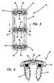
- FIG. 5 is a top planar view of anterior cervical plate system in a locked configuration according to the present invention.
- FIG. 6 is a cross-sectional view taken along line 6 - 6 of FIG. 5 of an anterior cervical plate system according to the present invention.
- FIG. 7 is a top perspective view of a plate according to the present invention.
- FIG. 8 is a top planar view of a plate according to the present invention.
- FIG. 9 is a cross-sectional view taken along line 9 - 9 of FIG. 8 of a plate according to the present invention.
- FIG. 10 is a sectional view of section 10 of FIG. 8 of a plate according to the present invention.
- FIG. 11 is a cross-sectional view taken along line 11 - 11 of FIG. 8 of a plate according to the present invention.
- FIG. 12 is a sectional view of section 12 of FIG. 11 of a plate according to the present invention.
- FIG. 13 is a cross-sectional view taken along line 13 - 13 of FIG. 12 of a plate according to the present invention.
- FIG. 14 is a top perspective view of a fastener according to the present invention.
- FIG. 15 is a side elevational view of a fastener according to the present invention.
- FIG. 16 is a top planar view of a fastener according to the present invention.
- FIG. 17 is a top perspective view of a lock according to the present invention.
- FIG. 18 is a top planar view of a lock according to the present invention.
- FIG. 19 is a cross-sectional view taken along line 19 - 19 of FIG. 18 of a lock according to the present invention.
- FIG. 20 is a bottom planar view of a lock according to the present invention.
- FIG. 21 is an end elevational view of a lock according to the present invention.
- FIG. 22 is a cross-sectional view taken along line 22 - 22 of FIG. 21 of a lock according to the present invention.
- FIG. 23 is a cross-sectional view taken along line 23 - 23 of FIG. 21 of a lock according to the present invention.
- FIG. 24 is an end elevational view of a lock according to the present invention.
- FIG. 25 is a top perspective view of an actuator according to the present invention.
- FIG. 26 is a top planar view of an actuator according to the present invention.
- FIG. 27 is a cross-sectional view taken along line 27 - 27 of FIG. 26 of an actuator according to the present invention.
- FIG. 28 is a side elevational view of an actuator according to the present invention.
- FIG. 29 is a cross-sectional view taken along line 29 - 29 of FIG. 28 of an actuator according to the present invention.
- FIG. 30 is a cross-sectional view taken along line 30 - 30 of FIG. 28 of an actuator according to the present invention.
- FIG. 31 is a top perspective view of a plate with actuators in locked configurations according to the present invention.
- FIG. 32 is a top perspective view of a plate with actuators and locks in locked configurations according to the present invention.
- FIG. 33 is a side elevational view of a plate with actuators and locks in locked configurations according to the present invention.
- FIG. 34 is a cross-sectional view taken along line 34 - 34 of FIG. 33 of a plate with an actuator and locks in a locked configuration according to the present invention.
- FIG. 35 is a top perspective view of a plate with actuators and locks in unlocked configurations according to the present invention.
- FIG. 36 is a side elevational view of a plate with actuators and locks in unlocked configurations according to the present invention.
- FIG. 37 is a cross-sectional view taken along line 37 - 37 of FIG. 36 of a plate with an actuator and locks in an unlocked configuration according to the present invention.
- FIG. 38 is a side elevational view of an actuator and two locks in an unlocked configuration according to the present invention.
- FIG. 39 is a cross-sectional view taken along line 39 - 39 of FIG. 38 of an actuator and two locks according to the present invention.
- FIG. 40 is a top perspective sectional view of a plate in an unlocked configuration according to the present invention.
- FIG. 41 is a side elevational view of an actuator and two locks in a locked configuration according to the present invention.
- FIG. 42 is a cross-sectional view taken along line 42 - 42 of FIG. 41 of an actuator and two locks in a locked configuration according to the present invention.
- FIG. 43 is a cross-sectional view taken along line 43 - 43 of FIG. 41 of an actuator and two locks in a locked configuration according to the present invention.
- FIG. 44 is a top perspective sectional view of a plate in a locked configuration according to the present invention.
- FIGS. 1-6 depict a cervical plate system 10 according to one variation of the invention that may be used to stabilize or fuse vertebral bodies in the cervical or other region of the spine.
- the anterior cervical plate system 10 that is shown in FIGS. 1-6 is a two-level bone fixation plate that is configured to span across and fixate three vertebrae of the cervical spine although the cervical plate system 10 may be a single level or any multilevel anterior cervical plate spanning two or more vertebral bodies.
- the anterior cervical plate system 10 comprises a plate 12 having fasteners 14 retained by locks 16 activated by actuators 18 .
- the cervical plate system 10 includes an unlocked position depicted in FIGS. 3-4 in which the locks 16 do not cover the fasteners 14 and locked position depicted in FIGS. 5-6 in which the actuators 18 are rotated to move the locks 16 into a fixed position covering the fasteners 14 .
- the plate 12 includes an upper surface 20 or anterior surface that faces the patient's soft tissue and esophagus when installed and a lower surface 22 or posterior surface facing the vertebral bodies to be immobilized.
- the upper surface 20 and lower surface 22 are interconnected by curved side walls and end walls to form a generally rectangular shape that is symmetrical about a midline.
- the gently curved structure of the rectangular plate 12 complements the natural curved structure of the vertebral bodies and lordotic curvature of the cervical spine.
- the corners of the plate are rounded to reduce or eliminate irritation of the esophagus and the surrounding tissue.
- the plate 12 is sized and shaped for use on an anterior aspect of the cervical spine although one skilled in the art may use the device in other regions of the spine and other skeletal fixations.
- the plate 12 which resides atop the vertebral bodies, has a low profile so as to minimally impinge on adjacent tissues.
- the plate 12 and other components of the cervical plate system 10 are made from suitable biocompatible material such as stainless steel, titanium and or any other metal or metal alloy.
- One or more components may be made of non-metal materials including but not limited to polymer, carbon reinforced polyetheretherketone (PEEK) or one or more biocompatible ceramics.
- the plate 12 may be additionally configured to promote bone ingrowth to the plate such as a portion of the plate being made of porous material or being roughened by mechanical blasting or plasma spraying with metal particles of one or more sizes.
- the plate 12 may also be coated with bio-active material, therapeutic agents for enhancing bone fusion and ingrowth, bone morphogenic proteins, growth factors and the like.
- the plate 12 includes a plurality of through holes 24 extending through the cervical plate 12 from the upper surface 20 and through the lower surface 22 .
- the holes 24 are configured to receive bone fasteners 14 passed there through.
- each hole 24 includes a head-receiving portion 26 near the upper surface 20 connected to a smaller shank-receiving portion 28 near the lower surface 22 to, thereby, in one variation, provide a seat for the head portion of the fastener 14 at a ledge formed at the intersection of the head-receiving portion 26 and shank-receiving portion 28 .
- the head-receiving portion 26 is recessed from the top surface 20 such that the head of the fastener 14 does not protrude beyond the upper surface 20 of the plate 12 in order to maintain a low profile for the plate 12 .
- Each through hole 24 may have a scalloped or larger exit opening at the lower surface 22 to allow room for the angulation of inserted fasteners 14 .
- the head-receiving portion 26 is shaped to complement the shape of the head of the fastener 14 .
- the head-receiving portion 26 forms a frustoconical or curved surface configured for a complimentary frustoconical or curved outer surface of the fastener 14 .
- the size of the through hole 24 is configured such that the head-receiving portion 26 and shank-receiving portion 28 are both large enough to allow a bone fastener 14 to pass all the way through the plate 12 without any hindrance and a retention ring is employed in the through hole 24 to reduce the size of the through hole 24 such that the head portion of the fastener 14 is not allowed to pass through the retention ring.
- the shank-receiving portion 28 of the through hole 24 is smaller than the head-receiving portion 26 without the presence of a retention ring such that the head portion of a fastener 14 is not allowed to pass into the shank-receiving portion 28 of the through hole 24 and wherein the presence of the retention ring, if one is employed, further reduces the opening at the head-receiving portion 26 of the through hole 24 .
- An undercut (not shown) in the through hole 24 such as in the location of the head-receiving portion 26 may be formed and configured to mate with the fastener 14 or retention ring if one is used to, thereby, couple the retention ring to the through hole 24 as the retention ring is compressed and then inserted into or under the undercut.
- the through hole 24 is slightly elliptical in shape that matches a slightly elliptical retention ring which can be inserted in the conforming direction and then rotated into a non-conforming orientation to be retained within the through hole 24 by compression fit engagement therewith.
- FIGS. 7-13 depict a plate 12 having three sets or three pairs of fastener through holes 24 spaced-apart along the plate centerline for driving fasteners 14 into and stabilizing three vertebral bodies for creating a two-level construct.
- Each set of fastener through holes 24 includes two holes 24 spaced apart from each other along the centerline of the anterior cervical plate 12 .
- Each set or pair of through holes 24 is adapted for receiving two fasteners 14 to be driven into a single vertebral body.
- the longitudinal axes of a pair of through holes 24 diverge relative to each other such that a pair of fasteners 14 placed therein diverge slightly relative to each other at a desired angled as best seen in FIGS. 4 and 6 .
- the plate 12 further includes a recess 34 located between the through holes 24 of each pair of through holes 24 .
- the recess 34 extends between the two adjacent through holes 24 and is in communication or interconnected with them.
- the recess 34 is configured for receiving the locks 16 and actuator 18 such that the locks 16 and actuator 18 do not protrude from the upper surface 20 of the plate 12 in order to maintain the desired low profile and such that the locks 16 and the actuator 18 remain connected to the plate 12 .
- the recess 34 includes a base surface 39 best seen in FIGS. 10 and 13 .
- the recess 34 extends along a z-axis from the base surface 39 to the upper surface 20 of the plate 12 .
- a circular actuator well 36 is formed in the recess 34 at the centerline and is configured to receive and/or couple the actuator 18 to the plate 12 .
- the actuator 18 and well 36 are configured to snap-fit together or be connected together by any other means known in the art.
- the well 36 extends downwardly from the base surface 39 towards the lower surface 22 of the plate 12 .
- the recess 34 includes a first sidewall 35 oppositely disposed from a second sidewall 37 as best seen in FIGS. 12-13 .
- the sidewalls 35 , 37 extend from the base surface 39 of the recess 34 upwardly and interconnect to the upper surface 20 .
- Each of the sidewalls 35 , 37 includes a receiving portion 31 a , 31 b and an overhang portion 32 a , 32 b , respectively, as depicted in FIG. 12 .
- the receiving portion 31 a , 31 b is located between the base surface 39 and the overhang portion 32 a , 32 b .
- the overhang portion 32 a , 32 b transitions into the upper surface 20 .
- the plate 12 also includes two larger openings 38 located between each pair of through holes 24 that effectively reduce the overall weight of the plate 12 and provide a visualization pathway to monitor bone graft progress between the vertebral bodies.
- each overhang portion 32 a , 32 b in the location of the recess 34 includes an indentation or curved portion 33 a , 33 b interconnected between a stop 29 a , 29 b and a transition surface 27 a , 27 b .
- the indentation or curved portions 33 a , 33 b near the stop 29 a , 29 b partially covers the well 36 .
- the indentation or curved portion 33 a , 33 b may be curved throughout or may include straight surfaces as shown in FIG. 10 .
- the stop 29 a , 29 b is substantially a straight surface; however, the invention is not so limited.
- the stop 29 a , 29 b is configured to provide an abutment against at least a portion of the actuator 18 , in particular, the stop 29 a , 29 b serves as an abutment for the upper body of the actuator 18 as will be described in greater detail below.
- the overhang portion 32 a , 32 b is configured to not only retain the actuator 18 and locks 16 but also permit the actuator 18 to rotate relative to the plate 12 between a locked and unlocked orientation. In one variation, the actuator 18 is configured to rotate approximately 90 degrees relative to the plate 12 with the unlocked configuration at approximately zero degrees and the locked configuration at approximately 90 degrees.
- the stops 29 a , 29 b serve the limit the rotation of the actuator 18 relative to the plate 12 .
- the actuator 18 rotates clockwise into the locked position and counterclockwise into the unlocked position.
- the invention is not limited to the degree to which the actuator 18 rotates relative to the plate 12 .
- stop 29 a is directly opposite from the transition surface 27 b along the lateral axis and stop 29 b is directly opposite from transition surface 27 a .
- Stop 29 a is diagonally opposite from stop 29 b using the well 36 as a reference.
- the receiving portion 31 a , 31 b is configured to receive the locks 16 .
- the locks 16 are located in the receiving portion 31 a , 31 b along the sidewalls 35 , 37 , respectively, between the overhang portion 32 a , 32 b and the base surface 29 .
- the first sidewall 35 includes two protrusions 25 a , 25 b that extend inwardly toward the recess 34 .
- the second sidewall 37 includes two protrusions 23 a , 23 b that extend inwardly toward the recess 34 .
- the protrusions 25 a , 25 b are oppositely located from protrusions 23 a , 23 b , respectively.
- the protrusions 23 a , 23 b , 25 a , 25 b are configured to retain the locks 16 .
- the protrusions 23 a , 23 b , 25 a , 25 b are configured to retain the locks 16 from unlimited translation along the lateral axis of the plate.
- the protrusions 23 a , 23 b , 25 a , 25 b also retain the actuator 18 in the locked and unlocked positions.
- the actuator 18 when the actuator 18 is turned clockwise from the unlocked position to the locked position, the actuator 18 is turned past protrusions 23 a and 25 b which also assist in keeping the actuator 18 in the locked position.
- the actuator 18 when the actuator 18 is turned counterclockwise from the locked position to the unlocked position, the actuator is turned past protrusions 23 a and 25 b which also help to keep the actuator 18 in the unlocked position.
- the system may be configured such that clockwise rotation effects an unlocked orientation.
- an exemplary orthopedic fastener 14 that is preferably used with the cervical plate system 10 of the present invention is a bone screw 14 .
- the bone screw 14 includes a screw head 40 , neck 42 and threaded shank 44 .
- the head 40 includes a ledge 47 which is a surface along at least a portion of the perimeter of screw head 40 .
- the ledge 47 serves as an abutment surface for a complementary-shaped surface of the lock 16 that acts to cover and retain the fastener 14 to the plate 12 .
- the head 40 includes an instrument recess 46 for receiving a complementary tip of a surgical tool. A substantially hexagonal, daisy-shaped recess 46 is shown in FIGS.
- the recess 46 can be of any shape that allows a surgical tool to drive the bone screws 14 into the vertebral column.
- the head 40 of the bone screw 14 corresponds to the shape of the head-receiving portion 26 of the through hole 24 or, in an alternative variation, the inside of an associated retention ring if one is employed.
- Various bone screws 14 may be employed including ones capable of polyaxial, variable angle or fixed angled orientation with respect to the plate 12 with or without the ability to be locked down at a desired angle or orientation with respect to the plate 12 .
- the bone screws 14 are preferably self-tapping, however, other screws requiring holes to be drilled or pre-tapped can also be employed.
- Each lock 16 includes a top surface 48 and a bottom surface 49 interconnected by an actuator-facing surface 50 , a fastener-facing surface 51 , a first sidewall 52 and a second sidewall 53 .
- Two finger-like projections 54 , 55 extend outwardly from the actuator-facing side or surface 50 of the lock 16 .
- a first finger-like projection 54 has an inner surface 56 that transitions into the actuator-facing surface 50 and an outer surface 57 that transitions into the first sidewall 52 .
- the first sidewall 52 is substantially planar.
- the outer surface 57 of the first finger projection 54 is curved outwardly relative to the first sidewall 52 and forms a convex shape.
- the inner surface 56 is slightly curved and forms a substantially concave shape.
- the inner surface 56 may includes a substantially flat and straight surface between proximal and distal curved ends.
- the inner surface 56 and outer surface 57 intersect forming a hook-like feature 82 .
- the hook-like feature 82 is defined by the inner surface 56 or distal end extending toward the other finger-like projection 55 .
- the first finger-like projection 54 includes a top surface 86 and a bottom surface 88 that interconnect with the inner surface 56 and outer surface 57 to define the finger-like projection 54 .
- the bottom surface 88 of the finger-like projection 54 is aligned or substantially even with the bottom surface 49 of the lock 16 .
- the first finger-like projection 54 rises from the bottom surface 49 to approximately half the thickness of the actuator-facing surface 50 .
- a second finger-like projection 55 has an inner surface 89 that transitions into the actuator-facing surface 50 and an outer surface 90 that transitions into the second sidewall 53 .
- the outer surface 90 of the second finger projection 55 is curved outwardly relative to the second sidewall 53 and forms a convex shape.
- the inner surface 89 of the second finger-like projection 55 is substantially flat and straight except at the proximal end where the inner surface 89 curves as it transitions into the actuator-facing surface 50 .
- the inner surface 89 and outer surface 90 intersect without a hook-like feature.
- the second finger-like projection 55 includes a top surface 93 and a bottom surface 94 that interconnect with the inner surface 89 and outer surface 90 to define the finger-like projection 55 .
- the bottom surface 94 of the second finger-like projection 55 is at substantially the same height as the top surface 86 of the first finger-like projection 54 , that is approximately half-way beneath the top surface 48 of the lock 16 .
- the first finger-like projection 54 has approximately the same height as the second finger-like projection 55 .
- the top surface 48 of the lock 16 includes a scallop 84 near the actuator-facing surface 50 .
- the lock 16 includes a retaining flange 85 that extends outwardly from the fastener-facing surface 51 .
- the retaining flange 85 forms an overhang that is configured to cover and retain the fastener 14 when in the locked orientation.
- the retaining flange 85 includes a surface that substantially conforms to the ledge on the screw head 47 .
- Two locks 16 are employed for each actuator 18 . That is, one actuator 18 is used to simultaneously deploy two locks 16 between an unlocked orientation a locked orientation wherein in the locked orientation the retaining flange 85 of each lock 16 covers/retains the fastener 14 relative to the plate to substantially prevent each fastener 14 from backing out from the through hole 24 of the plate 12 .
- Two identical locks 16 are employed per level per actuator 18 . The two locks 16 are oriented with respect to each other such that the staggered finger-like projections 54 , 55 are stacked on top of each other.
- two locks 16 are oriented such that the actuator-facing surface 50 of each lock 16 are facing each other and the retaining flange 85 of each lock 16 are facing away from each other or toward the fastener 14 or fastener through hole 24 .
- the first finger-like projection 54 of a right first lock 16 is located beneath the second finger-like projection 55 of a left second lock 16 and the second finger-like projection 55 of the right first lock 16 is located above the first finger-like projection 54 of the left second lock 16 .
- Rotation of the actuator 18 pushes both first and second locks 16 outwardly toward the through holes 24 such that the retaining flange 85 of each lock 16 cover and retain respective fasteners 14 relative to the plate 12 in the locked orientation.
- the locks 16 translate laterally along the lateral axis between the locked position and the unlocked position.
- the locks 16 are retained with respect to the plate 12 by the surface 83 and surface 93 being located beneath the overhang portion 32 of the plate 12 .
- Surfaces 87 a and 87 b of the lock 16 are adjacent to transition surface 27 b and stop 29 a , respectively, and are located there between and permitted to slide there against.
- the surfaces 87 a , 87 b of the other lock 16 of the pair are adjacent to transition surface align with and are adjacent to overhang portions The locking and unlocking positions will be described in greater detail below.
- the actuator 18 includes a middle body 58 interconnected between an upper body 60 and a lower body 62 .
- the middle body 58 extends from a bottom surface 61 of the upper body 60 along the longitudinal axis of the actuator 18 to a top surface 63 of the lower body 62 .
- the middle body 58 includes an outer surface 59 and an inner surface 75 .
- the inner surface 75 defines an instrument recess 64 that opens at a top surface 65 of the upper body 60 .
- the instrument recess 64 is configured to receive an instrument to turn the actuator 18 with respect to the plate 12 .
- an oval or elliptical instrument recess 64 that is configured to match a complementarily-shaped instrument is shown in FIGS.
- an instrument recess 64 having any shape that is complementary to the instrument employed to activate, move or rotate the actuator 18 is within the scope of the present invention.
- the instrument recess 64 extends downwardly from the top surface 65 of the upper body 60 to a bottom surface 66 of the recess 64 .
- the middle body 58 has a cross-section taken perpendicular to the longitudinal axis of the actuator 18 .
- the outer surface 59 defines a shape having a length greater than a width wherein the length is defined perpendicular to the longitudinal axis of the actuator 18 and the width is defined perpendicular to the length and the longitudinal axis.
- the outer surface comprises first and second opposing surface portions 71 , 72 of the shape generally aligned with the length and third and fourth opposing portions 73 , 74 of the shape generally aligned with the width as seen in FIGS. 29 and 30 .
- the outer surface 59 of the middle body 58 can be described as elongate, oval, or rectangular with rounded corners.
- the first and second opposing surface portions are shown in the variation of FIGS. 25-30 to include substantially flat surface areas.
- the figures illustrate the inner surface 75 having the same shape as the outer surface 59 , the invention is not so limited and the inner surface 75 can correspond to the shape of any suitable driver instrument configured rotate the actuator 18 .
- the lower body 62 of the actuator 18 includes a top surface 63 and a bottom surface 67 interconnected by an outer surface 68 .
- the outer surface 68 includes a circumferential tapered surface 69 that tapers into the bottom surface 67 .
- the lower body 62 is circular in shape and is configured to be inserted into and to be received within the actuator well 36 of the plate 12 and rotate relative to the plate 12 .
- the actuator 18 may be configured snap into the plate 18 well 36 such that the actuator is connected yet free to rotate.
- the upper body 60 of the actuator 18 includes a top surface 65 interconnected to a bottom surface 61 by an outer surface 70 .
- the upper body 60 is a disc substantially defining a circle 76 .
- the upper body 60 includes two diametrically opposite tangential lines 77 , 78 that are substantially parallel to each other as best seen in FIG. 30 . These tangential lines 77 , 78 transition smoothly into abutment lines 79 , 80 , respectively.
- These abutment lines 79 , 80 form abutment surfaces in the upper body 60 that are configured to rotate into contact with stops 29 a , 29 b , respectively, in the unlocked orientation.
- tangential lines 77 , 78 and abutment lines 79 , 80 define two diametrically opposed protrusions 81 a , 81 b that extend outwardly.
- protrusions 81 a , 81 b need not necessarily be formed by the tangential lines 77 , 78 and abutment lines 79 , 80 and any suitable protrusion is within the scope of the present invention.
- the cervical plate system 10 is assembled by first inserting the actuators 18 into the recesses 34 such that the length of the middle body 58 of the actuator is substantially parallel to the lateral axis of the plate 12 which is the locked orientation of the actuator 18 .
- the lower body 62 is disposed inside the actuator well 36 of the plate 12 .
- the locks 16 are inserted into the recesses 34 .
- a first lock 16 with its finger-like projections 54 , 55 facing the actuator 18 is inserted on the right side of the actuator 18 and a second lock 16 with its finger-like projections 54 , 55 facing the actuator 18 is inserted on the left side of the actuator 18 .
- the finger-like projections are stacked or otherwise located above each other and adjacent to the first and second opposing surfaces 71 , 72 of the actuator 18 along the length of the shape of the middle body 58 .
- the third and fourth opposing surfaces 73 , 74 are oriented adjacent to the actuator-facing surfaces 50 of the locks 16 .
- the fingers 54 , 55 snap into place as their outer surfaces 57 , 90 slide past protrusions 23 a , 23 b , 25 a , 25 b .
- the overhang portion 32 of the plate 12 retains the locks 16 from falling out of the plate along the z-axis and the locks prevent the actuator from falling out of the plate as the locks 16 contact the top surface 63 of the lower body 62 of the actuator 18 to prevent them from z-axis translation wherein the z-axis in the figures is perpendicular to the face of the page.
- the retaining flange 85 of the locks 16 protrude into and above the through holes 24 for fastener 14 retention.
- the final step of assembly includes rotating the actuator 18 from the locked orientation shown in FIGS. 32-34 to the unlocked orientation shown in FIGS. 35-37 .
- the actuator 18 will be rotated clockwise in the view of FIG. 34 into the unlocked orientation.
- the middle body 58 will catch the hook-like features 82 on the first finger-like projections 54 , thereby pulling the locks 16 closer together and out of interference with the through holes 24 .
- the pulled-in or locked orientation of the locks 16 is shown in FIG.
- FIG. 38 there is shown an actuator 18 and two locks 16 a and 16 b in an unlocked orientation without the plate 12 .
- FIG. 38 shows finger 55 a of lock 16 a located above finger 54 b of lock 16 b .
- FIG. 39 also illustrates the actuator 18 and locks 16 a , 16 b in an unlocked orientation in which finger 54 a is adjacent to fourth opposing surface 74 , finger 54 b adjacent to the third opposing surface 73 , the actuator-facing surface 50 b adjacent to the first opposing surface 71 , and the actuator-facing surface 50 a adjacent to the second opposing surface 72 .
- the arrows in FIG. 39 indicate the clockwise direction in which the actuator 18 is to be rotated to achieve the locked configuration from the unlocked configuration.
- FIG. 29 shows the length of the shape of the middle body 58 being aligned with the longitudinal axis of the plate 12 .
- FIG. 40 illustrates the locks 16 a , 16 b inside the recess 34 with the retaining flanges 85 a , 85 b retracted and clear out of the way of the through holes 24 when in the unlocked configuration.
- Fasteners 14 may be inserted and removed when in the unlocked configuration.
- FIG. 41 there is shown an actuator 18 and two locks 16 a and 16 b in a locked orientation without the plate 12 .
- FIG. 41 shows the locks 16 a , 16 b extended away from the actuator 18 with the retaining flanges 85 a , 85 b in their most distally extended position for covering and retaining fasteners 14 .
- FIG. 41 shows the locks 16 a , 16 b extended away from the actuator 18 with the retaining flanges 85 a , 85 b in their most distally extended position for covering and retaining fasteners 14 .
- FIG. 42 illustrates the actuator 18 rotated into a locked position and locks 16 a , 16 b pushed apart in a locked orientation in which finger 54 a is adjacent to the first opposing surface 71 , finger 54 b adjacent to the second opposing surface 72 , the actuator-facing surface 50 b adjacent to the third opposing surface 73 , and the actuator-facing surface 50 a adjacent to the fourth opposing surface 74 .
- the arrows in FIG. 42 indicate the counterclockwise direction in which the actuator 18 is to be rotated to achieve the unlocked configuration from the locked configuration shown.
- FIG. 44 illustrates the locks 16 a , 16 b positioned inside the recess 34 with the retaining flanges 85 a , 85 b protruding into the pathway of the through holes 24 so as to retain fasteners 14 located therein. The fasteners 14 are prevented from backing out with respect to the plate 12 when in the locked configuration.
Abstract
Description
Claims (20)
Priority Applications (1)
| Application Number | Priority Date | Filing Date | Title |
|---|---|---|---|
| US14/159,024 US9629664B2 (en) | 2014-01-20 | 2014-01-20 | Anterior cervical plate |
Applications Claiming Priority (1)
| Application Number | Priority Date | Filing Date | Title |
|---|---|---|---|
| US14/159,024 US9629664B2 (en) | 2014-01-20 | 2014-01-20 | Anterior cervical plate |
Publications (2)
| Publication Number | Publication Date |
|---|---|
| US20150201982A1 US20150201982A1 (en) | 2015-07-23 |
| US9629664B2 true US9629664B2 (en) | 2017-04-25 |
Family
ID=53543800
Family Applications (1)
| Application Number | Title | Priority Date | Filing Date |
|---|---|---|---|
| US14/159,024 Active - Reinstated 2035-06-22 US9629664B2 (en) | 2014-01-20 | 2014-01-20 | Anterior cervical plate |
Country Status (1)
| Country | Link |
|---|---|
| US (1) | US9629664B2 (en) |
Cited By (14)
| Publication number | Priority date | Publication date | Assignee | Title |
|---|---|---|---|---|
| US20160135850A1 (en) * | 2014-11-19 | 2016-05-19 | Kyungpook National University Industry-Academic Cooperation Foundation | System for fixing cervical vertebrae, an apparatus for fixing cervical vertebrae and a driver used for an apparatus for fixing cervical vertebrae |
| US10154866B2 (en) | 2013-08-26 | 2018-12-18 | Kyungpook National University Industry-Academic Cooperation Foundation | Medical inserting apparatus |
| US10390863B2 (en) | 2015-12-29 | 2019-08-27 | Kyungpook National University Industry-Academic Cooperation Foundation | Rod connector |
| US10537666B2 (en) | 2015-05-18 | 2020-01-21 | Stryker European Holdings I, Llc | Partially resorbable implants and methods |
| US10575885B2 (en) | 2015-07-16 | 2020-03-03 | Kyungpook National University Industry-Academic Cooperation Foundation | Screw anchor assembly |
| US10603182B2 (en) | 2015-01-14 | 2020-03-31 | Stryker European Holdings I, Llc | Spinal implant with fluid delivery capabilities |
| US10729473B2 (en) | 2014-11-11 | 2020-08-04 | Kyungpook National University Industry-Academic Cooperation Foundation | System for fixing cervical vertebrae and a driver used for an apparatus for fixing cervical vertebrae |
| US10835388B2 (en) | 2017-09-20 | 2020-11-17 | Stryker European Operations Holdings Llc | Spinal implants |
| US10874445B2 (en) | 2015-10-13 | 2020-12-29 | Kyungpook National University Industry-Academic Cooperation Foundation | Screw fixing apparatus |
| US11000386B2 (en) | 2015-01-14 | 2021-05-11 | Stryker European Holdings I, Llc | Spinal implant with porous and solid surfaces |
| US11026726B2 (en) | 2012-06-29 | 2021-06-08 | K2M, Inc. | Minimal-profile anterior cervical plate and cage apparatus and method of using same |
| US11083509B2 (en) | 2016-06-08 | 2021-08-10 | Kyungpook National University Industry-Academic Cooperation Foundation | Screw anchor assembly and method of using the same in pedicle screw fixation |
| US11744619B2 (en) | 2018-04-06 | 2023-09-05 | K2M, Inc. | Faceted bone plate |
| USD1004776S1 (en) | 2022-01-20 | 2023-11-14 | Mirus Llc | Cervical plate |
Families Citing this family (11)
| Publication number | Priority date | Publication date | Assignee | Title |
|---|---|---|---|---|
| CN105476704B (en) * | 2015-12-17 | 2019-01-25 | 浙江康慈医疗科技有限公司 | Anterior locking cervical plate system |
| US10265109B2 (en) * | 2016-02-02 | 2019-04-23 | Life Spine, Inc. | Spine plate implant with cam lock bone screw retention |
| US11234742B2 (en) | 2017-11-16 | 2022-02-01 | Globus Medical, Inc. | Anterior cervical plate assembly |
| US11304734B2 (en) | 2017-11-16 | 2022-04-19 | Globus Medical Inc. | Anterior cervical plate assembly |
| US11229460B2 (en) * | 2017-11-16 | 2022-01-25 | Globus Medical, Inc. | Anterior cervical plate assembly |
| US11272963B2 (en) | 2017-11-16 | 2022-03-15 | Globus Medical, Inc. | Anterior cervical plate assembly |
| US11173042B2 (en) | 2019-11-26 | 2021-11-16 | GetSet Surgical SA | Spinal surgery devices, systems, and methods |
| USD925740S1 (en) | 2019-11-26 | 2021-07-20 | GetSet Surgical SA | Spinal fusion cage |
| US11278426B2 (en) | 2019-11-26 | 2022-03-22 | GetSet Surgical SA | Spinal surgery assemblies, systems, and methods |
| US11273057B2 (en) | 2019-11-26 | 2022-03-15 | GetSet Surgical SA | Spinal surgery instruments, systems, and methods |
| US11510708B2 (en) * | 2020-02-05 | 2022-11-29 | Adam Isaac Lewis | Thoracolumbar plate with cam lock |
Citations (170)
| Publication number | Priority date | Publication date | Assignee | Title |
|---|---|---|---|---|
| US5364399A (en) | 1993-02-05 | 1994-11-15 | Danek Medical, Inc. | Anterior cervical plating system |
| US5549612A (en) | 1992-11-25 | 1996-08-27 | Codman & Shurtleff, Inc. | Osteosynthesis plate system |
| US5616142A (en) | 1994-07-20 | 1997-04-01 | Yuan; Hansen A. | Vertebral auxiliary fixation device |
| US6045552A (en) | 1998-03-18 | 2000-04-04 | St. Francis Medical Technologies, Inc. | Spine fixation plate system |
| US6139550A (en) | 1997-02-11 | 2000-10-31 | Michelson; Gary K. | Skeletal plating system |
| US6398783B1 (en) | 1997-02-11 | 2002-06-04 | Sulzer Spine-Tech Inc. | Multi-lock anterior cervical plate |
| US20020120270A1 (en) | 2001-02-28 | 2002-08-29 | Hai Trieu | Flexible systems for spinal stabilization and fixation |
| US20030093082A1 (en) | 2000-06-26 | 2003-05-15 | Stryker Spine | Bone screw retaining system |
| US20030105466A1 (en) | 2001-11-30 | 2003-06-05 | Ralph James D. | Spacer device and insertion instrument for use in anterior cervical fixation surgery |
| US20030105462A1 (en) | 2001-11-30 | 2003-06-05 | Haider Thomas T. | Poly axial cervical plate system |
| US20030105467A1 (en) | 2001-11-30 | 2003-06-05 | Ralph James D. | Distraction instrument for use in anterior cervical fixation surgery |
| US20030125739A1 (en) | 2001-12-12 | 2003-07-03 | Bagga Charanpreet S. | Bioactive spinal implants and method of manufacture thereof |
| US20030135216A1 (en) | 2000-05-25 | 2003-07-17 | Sevrain Lionel C. | Anchoring system for fixing objects to bones |
| US6599290B2 (en) | 2001-04-17 | 2003-07-29 | Ebi, L.P. | Anterior cervical plating system and associated method |
| US6602255B1 (en) | 2000-06-26 | 2003-08-05 | Stryker Spine | Bone screw retaining system |
| US20030153920A1 (en) | 2002-02-13 | 2003-08-14 | Ralph James D. | Longitudinal plate assembly having an adjustable length |
| US20030171753A1 (en) | 2001-10-25 | 2003-09-11 | Corin Limited | Surgical implant |
| US6626907B2 (en) | 1998-05-19 | 2003-09-30 | Alphatec Manufacturing, Inc. | Anterior cervical plate and fixation system |
| US20030187509A1 (en) | 2002-04-01 | 2003-10-02 | Lemole G. Michael | Modulus plating system and method |
| US20030187440A1 (en) | 2002-03-12 | 2003-10-02 | Marc Richelsoph | Bone plate and screw retaining mechanism |
| US6652525B1 (en) | 1998-04-30 | 2003-11-25 | Sofamor S.N.C. | Anterior implant for the spine |
| US20030229348A1 (en) | 2000-05-25 | 2003-12-11 | Sevrain Lionel C. | Auxiliary vertebrae connecting device |
| US20030236528A1 (en) | 2002-06-24 | 2003-12-25 | Thramann Jeffrey J | Impactor for use with cervical plate |
| US20040015169A1 (en) | 2002-07-16 | 2004-01-22 | Larry Gause | Bone plate fastener retaining mechanisms and methods |
| US20040019353A1 (en) | 2002-02-01 | 2004-01-29 | Freid James M. | Spinal plate system for stabilizing a portion of a spine |
| US20040024081A1 (en) | 2001-02-22 | 2004-02-05 | Trieu Hai H. | Bioactive nanocomposites and methods for their use |
| US20040030336A1 (en) | 2002-08-06 | 2004-02-12 | Khanna Rohit Kumar | Anterior cervical spine stabilization method and system |
| US20040034352A1 (en) | 2002-08-16 | 2004-02-19 | Needham Dusty Anna | Systems, instrumentation and techniques for retaining fasteners relative to a bone plate |
| US20040049279A1 (en) | 2000-05-25 | 2004-03-11 | Sevrain Lionel C. | Inter-vertebral disc prosthesis for rachis through anterior surgery thereof |
| US20040068319A1 (en) | 2002-10-04 | 2004-04-08 | Cordaro Nicholas M. | Cervical plate/screw system for immobilizing vertebral bodies |
| US20040087951A1 (en) | 2002-11-04 | 2004-05-06 | Khalili Farid Bruce | Fastener retention system |
| US20040092947A1 (en) | 2002-09-30 | 2004-05-13 | Foley Kevin T. | Devices and methods for securing a bone plate to a bony segment |
| US20040092929A1 (en) | 2002-09-27 | 2004-05-13 | Zindrick Michael R. | Spinal plate with means to secure a graft |
| US20040097938A1 (en) | 2002-07-24 | 2004-05-20 | Neville Alleyne | Compressible fixation apparatus for spinal surgery |
| US20040097925A1 (en) | 2002-06-07 | 2004-05-20 | Boehm Frank H. | Cervical spine stabilizing system and method |
| US20040097950A1 (en) | 1999-10-13 | 2004-05-20 | Foley Kevin T. | System and method for securing a plate to a spinal column |
| US20040097934A1 (en) | 1997-05-15 | 2004-05-20 | Farris Robert A. | Anterior cervical plating system |
| US20040127897A1 (en) | 2000-01-06 | 2004-07-01 | Jim Freid | System and method for stabilizing the human spine with a bone plate |
| US20040127899A1 (en) | 2002-12-31 | 2004-07-01 | Konieczynski David D. | Bone plate and screw system allowing bi-directional attachment |
| US20040127900A1 (en) | 2002-12-31 | 2004-07-01 | Konieczynski David D. | Resilient bone plate and screw system allowing bi-directional assembly |
| US20040133205A1 (en) | 2002-06-24 | 2004-07-08 | Jeffrey Thramann | Cervical plate |
| US20040177847A1 (en) | 2003-03-10 | 2004-09-16 | Foley Kevin T. | Posterior pedicle screw and plate system and methods |
| US20040181226A1 (en) | 2001-06-04 | 2004-09-16 | Michelson Gary K. | Method for installing dynamic, modular, single-lock anterior cervical plate system having assembleable and moveable segments |
| US20040181229A1 (en) | 2001-06-04 | 2004-09-16 | Michelson Gary K. | Instrumentation for use with dynamic single-lock anterior cervical plate system having non-detachably fastened and moveable segments |
| US20040186476A1 (en) | 2001-06-06 | 2004-09-23 | Michelson Gary K. | Method for installing dynamic, modular, multilock anterior cervical plate system having detachably fastened assembleable and moveable segments |
| US20040204713A1 (en) | 2003-01-10 | 2004-10-14 | Abdou M. Samy | Plating system for bone fixation and subsidence and method of implantation |
| US20040204712A1 (en) | 2003-04-09 | 2004-10-14 | Eric Kolb | Bone fixation plates |
| US20040204710A1 (en) | 2003-04-09 | 2004-10-14 | Tushar Patel | Drill guide and plate inserter |
| US20040210314A1 (en) | 2000-07-10 | 2004-10-21 | Michelson Gary K. | Flanged interbody spinal fusion implants |
| US20040215195A1 (en) | 2003-04-25 | 2004-10-28 | Sdgi Holdings, Inc. | Non-metallic orthopedic plate |
| US20040215192A1 (en) | 2000-03-01 | 2004-10-28 | Justis Jeff R | Superelastic spinal stabilization system and method |
| US20040220571A1 (en) | 1998-04-30 | 2004-11-04 | Richard Assaker | Bone plate assembly |
| US20040225290A1 (en) | 2001-03-27 | 2004-11-11 | Nuvasive, Inc. | Hinged anterior thoracic/lumbar plate |
| US20040236333A1 (en) | 2003-03-21 | 2004-11-25 | Lin Paul S. | Uniplate cervical device |
| US20040243128A1 (en) | 2001-05-17 | 2004-12-02 | Howland Robert S. | Selective axis posterior lumbar spinal plating fixation apparatus and methods for use |
| US20040260306A1 (en) | 2003-06-20 | 2004-12-23 | Fallin T. Wade | Method and apparatus for bone plating |
| US20050015092A1 (en) | 2003-07-16 | 2005-01-20 | Rathbun David S. | Plating system with multiple function drill guide |
| US20050027296A1 (en) | 2002-06-24 | 2005-02-03 | Jeffrey Thramann | Cervical plate with backout protection |
| US20050033298A1 (en) | 2001-10-31 | 2005-02-10 | Ortho Development Corporation | Cervical plate for stabilizing the human spine |
| US20050043732A1 (en) | 2003-08-18 | 2005-02-24 | Dalton Brian E. | Cervical compression plate assembly |
| US20050059970A1 (en) | 2003-09-17 | 2005-03-17 | Eric Kolb | Bone fixation systems |
| US20050075633A1 (en) | 2003-10-02 | 2005-04-07 | Thomas Ross | Anterior cervical plate |
| US20050085816A1 (en) | 2001-06-04 | 2005-04-21 | Michelson Gary K. | Method for installation of dynamic anterior cervical plate system having moveable segments |
| US20050137597A1 (en) | 2003-12-22 | 2005-06-23 | Life Spine | Dynamic cervical plates and cervical plate constructs |
| US20050149021A1 (en) | 2003-12-23 | 2005-07-07 | Tozzi James E. | Spinal implant device |
| US20050171551A1 (en) | 2003-10-21 | 2005-08-04 | William Sukovich | Instrument and method for preparing a bone to receive an implant |
| US20050177161A1 (en) | 2004-02-10 | 2005-08-11 | Baynham Bret O. | Static anterior cervical plate |
| US20050177163A1 (en) | 2003-12-29 | 2005-08-11 | Abdou M. S. | Plating system for bone fixation and method of implantation |
| US20050177160A1 (en) | 2004-02-10 | 2005-08-11 | Baynham Bret O. | Dynamic cervical plate |
| US20050187553A1 (en) | 2001-08-24 | 2005-08-25 | Grabowski John J. | Bone fixation device |
| US20050187554A1 (en) | 2001-06-04 | 2005-08-25 | Michelson Gary K. | Method for installation of anterior cervical plate system having vertebral body engaging anchors and connecting plate |
| US20050192576A1 (en) | 2001-06-06 | 2005-09-01 | Michelson Gary K. | Method for installing dynamic multilock anterior cervical plate system having detachably fastened and moveable segments |
| US20050208095A1 (en) | 2003-11-20 | 2005-09-22 | Angiotech International Ag | Polymer compositions and methods for their use |
| US20050209593A1 (en) | 2004-03-06 | 2005-09-22 | Depuy Spine, Inc. | Flexible anterior cervical plate |
| US20050228386A1 (en) | 2004-04-08 | 2005-10-13 | Tara Ziolo | Bone fixation device |
| US20050234455A1 (en) | 2004-04-19 | 2005-10-20 | Lawrence Binder | Bone fixation plate |
| US20050261690A1 (en) | 2004-04-19 | 2005-11-24 | Binder Lawrence J | Bone fixation plate |
| US20050277938A1 (en) | 2004-05-27 | 2005-12-15 | Depuy Spine, Inc. | Tri-joint implant methods |
| US20050283152A1 (en) * | 2004-06-17 | 2005-12-22 | Lindemann Gary S | Method and apparatus for retaining screws in a plate |
| US20060009845A1 (en) | 2004-07-08 | 2006-01-12 | Chin Kingsley R | Method and device for kinematic retaining cervical plating |
| US20060030852A1 (en) | 2002-11-13 | 2006-02-09 | Sevrain Lionel C | Anchoring system for fixing objects to bones |
| US20060079961A1 (en) | 2001-01-23 | 2006-04-13 | Michelson Gary K | Implant with trailing end adapted to receive bone screws |
| US20060082015A1 (en) | 2004-09-30 | 2006-04-20 | Inion Ltd. | Surgical implant shaping instrument, surgical system and method |
| US20060149256A1 (en) | 1997-08-04 | 2006-07-06 | Wagner Erik J | System and method for stabilizing the human spine with a bone plate |
| US20060149251A1 (en) | 2004-12-22 | 2006-07-06 | Tara Ziolo | Bone fixation system |
| US20060155298A1 (en) | 2003-03-07 | 2006-07-13 | Theken Surgical, Llc | Instrument guide and implant holder |
| US20060161157A1 (en) | 2004-02-26 | 2006-07-20 | Lawrence Mosca | Bone plate system and methods |
| US20060167456A1 (en) | 2004-12-21 | 2006-07-27 | Packaging Service Corporation Of Kentucky | Cervical plate system |
| US20060189997A1 (en) | 2005-02-10 | 2006-08-24 | Zimmer Spine, Inc. | All through one drill guide for cervical plating |
| US20060200147A1 (en) | 2005-02-18 | 2006-09-07 | Ensign Michael D | Orthopedic plate system and method for using the same |
| US20060200134A1 (en) | 2002-02-01 | 2006-09-07 | James Freid | Spinal plate system for stabilizing a portion of a spine |
| US20060229620A1 (en) | 2005-03-03 | 2006-10-12 | Accin Corporation | Method and apparatus for providing a retainer for a bone stabilization device |
| US20060235405A1 (en) | 2005-03-31 | 2006-10-19 | Hawkes David T | Active compression orthopedic plate system and method for using the same |
| US20060241611A1 (en) | 2005-04-12 | 2006-10-26 | Frank Castro | Modular spinal implant system to assist with cervical stabilization |
| US20060241616A1 (en) | 2002-12-31 | 2006-10-26 | Depuy Spine, Inc. | Bone Plate and Resilient Screw System Allowing Bi-Directional Assembly |
| EP1520545B1 (en) | 2003-10-01 | 2006-11-29 | Warsaw Orthopedic, Inc. | Spinal device locking mechanism |
| US20060276792A1 (en) | 2005-05-25 | 2006-12-07 | Ensign Michael D | Low profile pedicle screw and rod assembly |
| US20060287653A1 (en) | 2005-06-15 | 2006-12-21 | Stryker Spine | Anterior cervical plate |
| US7186254B2 (en) | 2002-02-25 | 2007-03-06 | Dinh Dzung H | Methods and apparatus for promoting fusion of vertebrae |
| WO2007037774A1 (en) | 2005-04-26 | 2007-04-05 | Innovative Spinal Design | Dynamic cervical plate |
| US20070083203A1 (en) | 2005-09-16 | 2007-04-12 | Ribeiro Helio M | Anterior cervical plating system |
| US20070123884A1 (en) | 2005-11-09 | 2007-05-31 | Abdou M S | Bone fixation systems and methods of implantation |
| US20070185489A1 (en) | 2006-01-26 | 2007-08-09 | Abdou M S | Devices and Methods for Inter-Vertebral Orthopedic Device Placement |
| US20070203492A1 (en) | 1999-10-13 | 2007-08-30 | Needham Dusty A | Anterior cervical plating system and method |
| WO2007101266A1 (en) | 2006-03-01 | 2007-09-07 | Warsaw Orthopedic, Inc. | Low profile spinal rod connector system |
| US20070213828A1 (en) | 2000-10-25 | 2007-09-13 | Trieu Hai H | Non-metallic implant devices and intra-operative methods for assembly and fixation |
| US20070213728A1 (en) | 2006-03-07 | 2007-09-13 | Sdgi Holdings, Inc. | Methods and devices for retaining bone plate anchors |
| US20070213820A1 (en) | 2003-04-23 | 2007-09-13 | Sepitec Foundation | Spondylodesis Device |
| US20070213729A1 (en) | 2006-03-08 | 2007-09-13 | Sdgi Holdings, Inc. | Flexible bone plates and methods for dynamic spinal stabilization |
| WO2007103081A2 (en) | 2006-03-02 | 2007-09-13 | The Cleveland Clinic Foundation | Asymmetrical cervical fusion plate and method for use |
| US7273481B2 (en) | 2002-10-28 | 2007-09-25 | Blackstone Medical, Inc. | Bone plate assembly provided with screw locking mechanisms |
| US20070225707A1 (en) | 2006-03-22 | 2007-09-27 | Sdgi Holdings, Inc. | Orthopedic spinal devices fabricated from two or more materials |
| US20070225717A1 (en) | 2006-03-21 | 2007-09-27 | Hawkes David T | Cervical pop rivet locking mechanism |
| US20070225718A1 (en) | 2006-03-22 | 2007-09-27 | Ensign Michael D | Rotolock cervical plate locking mechanism |
| US7276070B2 (en) | 2003-06-11 | 2007-10-02 | Mueckter Helmut | Osteosynthesis plate or comparable implant plus ball socket |
| US20070233119A1 (en) | 2006-03-10 | 2007-10-04 | Markworth Aaron D | Polyaxial occipital plate |
| US20070233110A1 (en) | 2006-03-14 | 2007-10-04 | Nabil L. Muhanna, M.D. | Vertebral plating system |
| US20070233117A1 (en) | 2006-02-21 | 2007-10-04 | Life Spine, Llc | Structure for joining and retaining multi-part orthopedic implants |
| US20070233072A1 (en) | 2006-03-01 | 2007-10-04 | Sdgi Holdings, Inc. | Modular fastener assemblies for spinal stabilization systems and methods |
| US20070233107A1 (en) | 2006-02-27 | 2007-10-04 | Zielinski Steven C | Method and apparatus for lateral reduction and fusion of the spine |
| US20070233108A1 (en) | 2006-03-15 | 2007-10-04 | Stalcup Gregory C | Spine fixation device |
| EP1841376A2 (en) | 2005-01-12 | 2007-10-10 | Warsaw Orthopedic, Inc. | Anchor retaining mechanisms for bone plates |
| US20070239158A1 (en) | 2006-04-10 | 2007-10-11 | Sdgi Holdings, Inc. | Elastic plates for spinal fixation or stabilization |
| EP1847229A2 (en) | 1997-02-11 | 2007-10-24 | Warsaw Orthopedic, Inc. | Single lock skeletal plating system |
| US7288094B2 (en) | 2005-06-10 | 2007-10-30 | Sdgi Holdings, Inc. | System and method for retaining screws relative to a vertebral plate |
| US7288095B2 (en) | 2004-08-12 | 2007-10-30 | Atlas Spine, Inc. | Bone plate with screw lock |
| US7291152B2 (en) | 2003-04-18 | 2007-11-06 | Abdou M Samy | Bone fixation system and method of implantation |
| US20070270965A1 (en) | 2006-04-28 | 2007-11-22 | Joe Ferguson | Orthopedic support locating or centering feature and method |
| WO2007134199A2 (en) | 2006-05-10 | 2007-11-22 | Biomerix Corp | Spinal implants and devices and methods for their controlled insertion |
| US20070270851A1 (en) | 2006-04-28 | 2007-11-22 | David Erickson | Radiolucent bone plate systems and methods of use |
| US20070276405A1 (en) | 2002-11-19 | 2007-11-29 | Huebner Randall J | Adjustable bone plates |
| US20070276371A1 (en) | 2004-02-10 | 2007-11-29 | Baynham Bret O | Dynamic cervical plate |
| US20080208341A1 (en) | 2006-12-29 | 2008-08-28 | Providence Medical Technology, Inc. | Cervical distraction method |
| US20080208262A1 (en) | 2007-02-26 | 2008-08-28 | Butler Michael S | Spine plate with bone screw relief area |
| US20080208260A1 (en) | 2007-02-22 | 2008-08-28 | Csaba Truckai | Spine treatment devices and methods |
| US20080215097A1 (en) | 2006-03-30 | 2008-09-04 | Ensign Michael D | Active Compression Orthopedic Plate System and Method for Using the Same |
| US20080228226A1 (en) | 2007-03-12 | 2008-09-18 | Arya Nick Shamie | Cervical support system |
| US20080234755A1 (en) | 2007-01-29 | 2008-09-25 | Polaris Biotechnology, Inc. | Craniospinal fusion method and apparatus |
| US20080234681A1 (en) | 2004-02-10 | 2008-09-25 | Baynham Matthew G | Dynamic cervical plate |
| US20080234751A1 (en) | 2007-01-31 | 2008-09-25 | Mcclintock Larry E | Anterior vertebral plate with closed thread screw |
| US20080234750A1 (en) | 2007-01-31 | 2008-09-25 | Woods Richard W | Anterior vertebral plate with taper lock screw |
| US20080234753A1 (en) | 2007-03-19 | 2008-09-25 | Warsaw Orthopedic, Inc. | Spinal Stabilization Systems |
| US20080234680A1 (en) | 2007-01-26 | 2008-09-25 | Structure Medical, Inc. | Interlock for dynamic bone fixation plates |
| US20080234689A1 (en) | 2007-02-21 | 2008-09-25 | Warsaw Orthopedic, Inc. | Vertebral Plate Measuring Device and Method of Use |
| US20080234752A1 (en) | 2007-03-21 | 2008-09-25 | The University Of North Carolina At Chapel Hill | Surgical plate puller devices and methods for use with surgical bone screw/plate systems |
| US20080234748A1 (en) | 2007-01-31 | 2008-09-25 | Wallenstein Todd M | Anterior vertebral plate with quick lock screw |
| US20080234749A1 (en) | 2007-01-26 | 2008-09-25 | Zimmer Technology, Inc. | Bone plate providing threaded locking head screw capture |
| US20080288001A1 (en) | 2007-05-18 | 2008-11-20 | Trace Cawley | Cervical plate locking mechanism and associated surgical method |
| US20080287999A1 (en) | 2007-05-18 | 2008-11-20 | Markworth Aaron D | Anterior cervical plate with independent spring-loaded locking slides for each screw |
| US20090131988A1 (en) | 2007-11-09 | 2009-05-21 | Stryker Spine | Cervical plate with a feedback device for selective association with bone screw blocking mechanism |
| US20090149888A1 (en) | 2007-12-07 | 2009-06-11 | Custom Spine, Inc. | Orthopedic anti back-out mechanism |
| US20090177237A1 (en) | 2008-01-04 | 2009-07-09 | Spartek Medical, Inc. | Cervical spine implant system and method |
| US20090177239A1 (en) | 2007-08-06 | 2009-07-09 | Michael Castro | Cervical plate instrument kit |
| US20090182383A1 (en) | 2008-01-14 | 2009-07-16 | Amedica Corporation | Bone fixation plate with anchor retaining member |
| WO2009089395A2 (en) | 2008-01-08 | 2009-07-16 | Polaris Biotechnology, Inc. | Osteointegration apparatus |
| US20090182341A1 (en) | 2002-03-12 | 2009-07-16 | Cervitech, Inc. | Instrument set for fitting an intervertebral jont prosthesis |
| WO2009091770A1 (en) | 2008-01-17 | 2009-07-23 | Warsaw Orthopedic, Inc. | Spinal osteosynthesis device |
| WO2009091775A2 (en) | 2008-01-17 | 2009-07-23 | Warsaw Orthopedic, Inc. | Intervertebral cage and vertebral fusion device |
| US20090187218A1 (en) | 2008-01-17 | 2009-07-23 | Amedica Corporation | Bone fixation plate with wire members for resisting back out of bone anchors |
| US20090192549A1 (en) | 2008-01-30 | 2009-07-30 | Ebi, Llc | Bone plating system |
| US20090210008A1 (en) | 2008-02-20 | 2009-08-20 | Life Spine, Inc. | Modular spine plate with projection and socket interface |
| US20090222049A1 (en) | 2005-11-16 | 2009-09-03 | Robert Frigg | Device for Bone Fixation with at least one Through Hole |
| US7601170B2 (en) | 2004-12-13 | 2009-10-13 | Kyphon Sarl | Inter-cervical facet implant and method |
| US20090270926A1 (en) | 2008-04-24 | 2009-10-29 | Hawkes David T | Rotolock cervical plate locking mechanism |
| US20100042159A1 (en) | 2008-07-17 | 2010-02-18 | Alphatec Spine, Inc. | Bone plate assembly |
| US20100049256A1 (en) | 2007-01-30 | 2010-02-25 | Dong Myung Jeon | Anterior cerivcal plating system |
| US20100234897A1 (en) | 2009-03-13 | 2010-09-16 | Lanx, Inc. | Spinal plate assemblies with backout protection cap and methods |
| US20110106159A1 (en) | 2008-06-05 | 2011-05-05 | Seaspine, Inc. | Spinal fixation plate assembly |
| US20110118784A1 (en) | 2004-02-10 | 2011-05-19 | Baynham Bret O | Cervical Plate Ratchet Pedicle Screws |
| US8668723B2 (en) | 2011-07-19 | 2014-03-11 | Neurostructures, Inc. | Anterior cervical plate |
-
2014
- 2014-01-20 US US14/159,024 patent/US9629664B2/en active Active - Reinstated
Patent Citations (230)
| Publication number | Priority date | Publication date | Assignee | Title |
|---|---|---|---|---|
| US5549612A (en) | 1992-11-25 | 1996-08-27 | Codman & Shurtleff, Inc. | Osteosynthesis plate system |
| US5616144A (en) | 1992-11-25 | 1997-04-01 | Codman & Shurtleff, Inc. | Osteosynthesis plate system |
| US5364399A (en) | 1993-02-05 | 1994-11-15 | Danek Medical, Inc. | Anterior cervical plating system |
| US5616142A (en) | 1994-07-20 | 1997-04-01 | Yuan; Hansen A. | Vertebral auxiliary fixation device |
| EP1847229A2 (en) | 1997-02-11 | 2007-10-24 | Warsaw Orthopedic, Inc. | Single lock skeletal plating system |
| US20040236335A1 (en) | 1997-02-11 | 2004-11-25 | Michelson Gary K. | Plate apparatus for the spine |
| US6398783B1 (en) | 1997-02-11 | 2002-06-04 | Sulzer Spine-Tech Inc. | Multi-lock anterior cervical plate |
| US20050187552A1 (en) | 1997-02-11 | 2005-08-25 | Michelson Gary K. | Multilock anterior cervical plating system |
| US20040122426A1 (en) | 1997-02-11 | 2004-06-24 | Michelson Gary K. | Bone plate having a portion adapted to overlie a fastener |
| US20030181912A1 (en) | 1997-02-11 | 2003-09-25 | Michelson Gary K. | Anterior cervical plating system and bone screw |
| US6139550A (en) | 1997-02-11 | 2000-10-31 | Michelson; Gary K. | Skeletal plating system |
| US20040236334A1 (en) | 1997-02-11 | 2004-11-25 | Michelson Gary K. | Plating apparatus and system having a retaining element |
| US20050038436A1 (en) | 1997-02-11 | 2005-02-17 | Michelson Gary K. | System and method for stabilizing a portion of the spine |
| US20030191471A1 (en) | 1997-02-11 | 2003-10-09 | Michelson Gary K. | Multilock anterior cervical plating system |
| US20050059971A1 (en) | 1997-02-11 | 2005-03-17 | Michelson Gary K. | Plating system having retaining member that permits movement of at least one bone fastener |
| US20030191472A1 (en) | 1997-02-11 | 2003-10-09 | Michelson Gary K. | Multilock anterior cervical plating system |
| US20040220572A1 (en) | 1997-02-11 | 2004-11-04 | Michelson Gary K | Skeletal plating system |
| US20040097934A1 (en) | 1997-05-15 | 2004-05-20 | Farris Robert A. | Anterior cervical plating system |
| US20060149256A1 (en) | 1997-08-04 | 2006-07-06 | Wagner Erik J | System and method for stabilizing the human spine with a bone plate |
| US6045552A (en) | 1998-03-18 | 2000-04-04 | St. Francis Medical Technologies, Inc. | Spine fixation plate system |
| US20100069968A1 (en) | 1998-04-30 | 2010-03-18 | Sofamor S.N.C. | Anterior implant for the spine |
| US20040220571A1 (en) | 1998-04-30 | 2004-11-04 | Richard Assaker | Bone plate assembly |
| US20040158246A1 (en) | 1998-04-30 | 2004-08-12 | Sofamor S.N.C. | Anterior implant for the spine |
| US6652525B1 (en) | 1998-04-30 | 2003-11-25 | Sofamor S.N.C. | Anterior implant for the spine |
| US6626907B2 (en) | 1998-05-19 | 2003-09-30 | Alphatec Manufacturing, Inc. | Anterior cervical plate and fixation system |
| US20070203492A1 (en) | 1999-10-13 | 2007-08-30 | Needham Dusty A | Anterior cervical plating system and method |
| US20040097950A1 (en) | 1999-10-13 | 2004-05-20 | Foley Kevin T. | System and method for securing a plate to a spinal column |
| US20040127897A1 (en) | 2000-01-06 | 2004-07-01 | Jim Freid | System and method for stabilizing the human spine with a bone plate |
| US6964664B2 (en) | 2000-01-06 | 2005-11-15 | Spinal Concepts Inc. | System and method for stabilizing the human spine with a bone plate |
| US20040215192A1 (en) | 2000-03-01 | 2004-10-28 | Justis Jeff R | Superelastic spinal stabilization system and method |
| US20030135216A1 (en) | 2000-05-25 | 2003-07-17 | Sevrain Lionel C. | Anchoring system for fixing objects to bones |
| US20040006343A1 (en) | 2000-05-25 | 2004-01-08 | Sevrain Lionel C. | Auxiliary vertebrae connecting device |
| US20030229348A1 (en) | 2000-05-25 | 2003-12-11 | Sevrain Lionel C. | Auxiliary vertebrae connecting device |
| US20040049279A1 (en) | 2000-05-25 | 2004-03-11 | Sevrain Lionel C. | Inter-vertebral disc prosthesis for rachis through anterior surgery thereof |
| US20030093082A1 (en) | 2000-06-26 | 2003-05-15 | Stryker Spine | Bone screw retaining system |
| US20050149027A1 (en) | 2000-06-26 | 2005-07-07 | Stryker Spine | Bone screw retaining system |
| US7887547B2 (en) | 2000-06-26 | 2011-02-15 | Stryker Spine | Bone screw retaining system |
| US6602255B1 (en) | 2000-06-26 | 2003-08-05 | Stryker Spine | Bone screw retaining system |
| US20040210314A1 (en) | 2000-07-10 | 2004-10-21 | Michelson Gary K. | Flanged interbody spinal fusion implants |
| US20070213828A1 (en) | 2000-10-25 | 2007-09-13 | Trieu Hai H | Non-metallic implant devices and intra-operative methods for assembly and fixation |
| US20060079961A1 (en) | 2001-01-23 | 2006-04-13 | Michelson Gary K | Implant with trailing end adapted to receive bone screws |
| US20040106924A1 (en) | 2001-02-15 | 2004-06-03 | Ralph James D. | Longitudinal plate assembly having an adjustable length |
| US20040024081A1 (en) | 2001-02-22 | 2004-02-05 | Trieu Hai H. | Bioactive nanocomposites and methods for their use |
| US20020120270A1 (en) | 2001-02-28 | 2002-08-29 | Hai Trieu | Flexible systems for spinal stabilization and fixation |
| US20040225290A1 (en) | 2001-03-27 | 2004-11-11 | Nuvasive, Inc. | Hinged anterior thoracic/lumbar plate |
| US20080228230A1 (en) | 2001-03-27 | 2008-09-18 | Nuvasive, Inc. | Hinged Bone Plate and Related Methods |
| US6599290B2 (en) | 2001-04-17 | 2003-07-29 | Ebi, L.P. | Anterior cervical plating system and associated method |
| US20030208204A1 (en) | 2001-04-17 | 2003-11-06 | Bailey Kirk J. | Anterior cervical plating system |
| US20050216005A1 (en) | 2001-05-17 | 2005-09-29 | Howland Robert S | Selective axis anchor screw posterior lumbar plating system |
| US20040243128A1 (en) | 2001-05-17 | 2004-12-02 | Howland Robert S. | Selective axis posterior lumbar spinal plating fixation apparatus and methods for use |
| US20060085001A1 (en) | 2001-06-04 | 2006-04-20 | Michelson Gary K | Plate system having bone portion engaging anchors and connecting plate |
| US20050027297A1 (en) | 2001-06-04 | 2005-02-03 | Michelson Gary K. | Dynamic, modular, single-lock anterior cervical plate system having assembleable and moveable segments and instrumentation for installation thereof |
| US20050085816A1 (en) | 2001-06-04 | 2005-04-21 | Michelson Gary K. | Method for installation of dynamic anterior cervical plate system having moveable segments |
| US20050187554A1 (en) | 2001-06-04 | 2005-08-25 | Michelson Gary K. | Method for installation of anterior cervical plate system having vertebral body engaging anchors and connecting plate |
| US7824432B2 (en) | 2001-06-04 | 2010-11-02 | Warsaw Orthopedic, Inc. | Method for installation of dynamic anterior cervical plate system having moveable segments |
| US20110054528A1 (en) | 2001-06-04 | 2011-03-03 | Michelson Gary K | Dynamic plate system having moveable segments |
| US20040181226A1 (en) | 2001-06-04 | 2004-09-16 | Michelson Gary K. | Method for installing dynamic, modular, single-lock anterior cervical plate system having assembleable and moveable segments |
| US20040181229A1 (en) | 2001-06-04 | 2004-09-16 | Michelson Gary K. | Instrumentation for use with dynamic single-lock anterior cervical plate system having non-detachably fastened and moveable segments |
| US20050216010A1 (en) | 2001-06-04 | 2005-09-29 | Michelson Gary K | Method for installation of dynamic, single-lock anterior cervical plate system having non-detachably fastened and moveable segments |
| US7811285B2 (en) | 2001-06-04 | 2010-10-12 | Warsaw Orthopedic, Inc. | Dynamic, modular, single-lock anterior cervical plate system having assembleable and moveable segments and instrumentation for installation thereof |
| US7740630B2 (en) | 2001-06-04 | 2010-06-22 | Warsaw Orthopedic, Inc. | Anterior cervical plate system having vertebral body engaging anchors and connecting plate |
| US20090259226A1 (en) | 2001-06-04 | 2009-10-15 | Michelson Gary K | Method for installation of dynamic, single-lock anterior cervical plate system having non-detachably fastened and moveable segments |
| US20050192576A1 (en) | 2001-06-06 | 2005-09-01 | Michelson Gary K. | Method for installing dynamic multilock anterior cervical plate system having detachably fastened and moveable segments |
| US7803157B2 (en) | 2001-06-06 | 2010-09-28 | Warsaw Orthopedic, Inc. | Dynamic, modular, multilock anterior cervical plate system having detachably fastened assembleable and moveable segments and instrumentation for installation thereof |
| US20040186476A1 (en) | 2001-06-06 | 2004-09-23 | Michelson Gary K. | Method for installing dynamic, modular, multilock anterior cervical plate system having detachably fastened assembleable and moveable segments |
| US20050027298A1 (en) | 2001-06-06 | 2005-02-03 | Michelson Gary K. | Dynamic, modular, multilock anterior cervical plate system having detachably fastened assembleable and moveable segments and instrumentation for installation thereof |
| US20050216009A1 (en) | 2001-06-06 | 2005-09-29 | Michelson Gary K | Instrumentation for use with dynamic multilock anterior cervical plate system having non-detachably fastened and moveable segments |
| EP1429675B1 (en) | 2001-08-24 | 2007-10-24 | Zimmer Spine, Inc. | Bone fixation device |
| US20050187553A1 (en) | 2001-08-24 | 2005-08-25 | Grabowski John J. | Bone fixation device |
| US20030171753A1 (en) | 2001-10-25 | 2003-09-11 | Corin Limited | Surgical implant |
| US20050033298A1 (en) | 2001-10-31 | 2005-02-10 | Ortho Development Corporation | Cervical plate for stabilizing the human spine |
| US20030105466A1 (en) | 2001-11-30 | 2003-06-05 | Ralph James D. | Spacer device and insertion instrument for use in anterior cervical fixation surgery |
| US20030105462A1 (en) | 2001-11-30 | 2003-06-05 | Haider Thomas T. | Poly axial cervical plate system |
| US20040153088A1 (en) | 2001-11-30 | 2004-08-05 | Spinecore Inc. | Spacer device and insertion instrument for use in anterior cervical fixation surgery |
| US20040087945A1 (en) | 2001-11-30 | 2004-05-06 | Ralph James D. | Distraction instrument for use in anterior cervical fixation surgery |
| US20030105467A1 (en) | 2001-11-30 | 2003-06-05 | Ralph James D. | Distraction instrument for use in anterior cervical fixation surgery |
| US20030125739A1 (en) | 2001-12-12 | 2003-07-03 | Bagga Charanpreet S. | Bioactive spinal implants and method of manufacture thereof |
| US20060200134A1 (en) | 2002-02-01 | 2006-09-07 | James Freid | Spinal plate system for stabilizing a portion of a spine |
| US20040019353A1 (en) | 2002-02-01 | 2004-01-29 | Freid James M. | Spinal plate system for stabilizing a portion of a spine |
| US20030153920A1 (en) | 2002-02-13 | 2003-08-14 | Ralph James D. | Longitudinal plate assembly having an adjustable length |
| US7186254B2 (en) | 2002-02-25 | 2007-03-06 | Dinh Dzung H | Methods and apparatus for promoting fusion of vertebrae |
| US6695846B2 (en) | 2002-03-12 | 2004-02-24 | Spinal Innovations, Llc | Bone plate and screw retaining mechanism |
| US20030187440A1 (en) | 2002-03-12 | 2003-10-02 | Marc Richelsoph | Bone plate and screw retaining mechanism |
| US20090182341A1 (en) | 2002-03-12 | 2009-07-16 | Cervitech, Inc. | Instrument set for fitting an intervertebral jont prosthesis |
| US20040097935A1 (en) | 2002-03-12 | 2004-05-20 | Marc Richelsoph | Bone plate and screw retaining mechanism |
| US20030187442A1 (en) | 2002-03-12 | 2003-10-02 | Marc Richelsoph | Bone plate and screw retaining mechanism |
| US20030187509A1 (en) | 2002-04-01 | 2003-10-02 | Lemole G. Michael | Modulus plating system and method |
| US20040097925A1 (en) | 2002-06-07 | 2004-05-20 | Boehm Frank H. | Cervical spine stabilizing system and method |
| US20050027296A1 (en) | 2002-06-24 | 2005-02-03 | Jeffrey Thramann | Cervical plate with backout protection |
| US20040133205A1 (en) | 2002-06-24 | 2004-07-08 | Jeffrey Thramann | Cervical plate |
| US20070233120A1 (en) | 2002-06-24 | 2007-10-04 | Lanx, Llc | Cervical plate |
| US7175623B2 (en) | 2002-06-24 | 2007-02-13 | Lanx, Llc | Cervical plate with backout protection |
| US20030236528A1 (en) | 2002-06-24 | 2003-12-25 | Thramann Jeffrey J | Impactor for use with cervical plate |
| US20040015169A1 (en) | 2002-07-16 | 2004-01-22 | Larry Gause | Bone plate fastener retaining mechanisms and methods |
| US20040097938A1 (en) | 2002-07-24 | 2004-05-20 | Neville Alleyne | Compressible fixation apparatus for spinal surgery |
| US20040030336A1 (en) | 2002-08-06 | 2004-02-12 | Khanna Rohit Kumar | Anterior cervical spine stabilization method and system |
| US20040034352A1 (en) | 2002-08-16 | 2004-02-19 | Needham Dusty Anna | Systems, instrumentation and techniques for retaining fasteners relative to a bone plate |
| US20040092929A1 (en) | 2002-09-27 | 2004-05-13 | Zindrick Michael R. | Spinal plate with means to secure a graft |
| US20040092947A1 (en) | 2002-09-30 | 2004-05-13 | Foley Kevin T. | Devices and methods for securing a bone plate to a bony segment |
| US7220263B2 (en) | 2002-10-04 | 2007-05-22 | Seaspine, Inc. | Cervical plate/screw system for immobilizing vertebral bodies |
| US20040068319A1 (en) | 2002-10-04 | 2004-04-08 | Cordaro Nicholas M. | Cervical plate/screw system for immobilizing vertebral bodies |
| US7273481B2 (en) | 2002-10-28 | 2007-09-25 | Blackstone Medical, Inc. | Bone plate assembly provided with screw locking mechanisms |
| US7524325B2 (en) | 2002-11-04 | 2009-04-28 | Farid Bruce Khalili | Fastener retention system |
| US20040087951A1 (en) | 2002-11-04 | 2004-05-06 | Khalili Farid Bruce | Fastener retention system |
| US20060030852A1 (en) | 2002-11-13 | 2006-02-09 | Sevrain Lionel C | Anchoring system for fixing objects to bones |
| US20070276405A1 (en) | 2002-11-19 | 2007-11-29 | Huebner Randall J | Adjustable bone plates |
| US20050273105A1 (en) | 2002-12-31 | 2005-12-08 | Depuy Spine, Inc. | Bone plate and screw system allowing bi-directional assembly |
| US7651517B2 (en) | 2002-12-31 | 2010-01-26 | Depuy Acromed, Inc. | Bone plate and resilient screw system allowing bi-directional assembly |
| US20060241616A1 (en) | 2002-12-31 | 2006-10-26 | Depuy Spine, Inc. | Bone Plate and Resilient Screw System Allowing Bi-Directional Assembly |
| US20040127899A1 (en) | 2002-12-31 | 2004-07-01 | Konieczynski David D. | Bone plate and screw system allowing bi-directional attachment |
| US20040127900A1 (en) | 2002-12-31 | 2004-07-01 | Konieczynski David D. | Resilient bone plate and screw system allowing bi-directional assembly |
| US20040204713A1 (en) | 2003-01-10 | 2004-10-14 | Abdou M. Samy | Plating system for bone fixation and subsidence and method of implantation |
| US7278997B1 (en) | 2003-03-07 | 2007-10-09 | Theken Spine, Llc | Instrument guide and implant holder |
| US20060155298A1 (en) | 2003-03-07 | 2006-07-13 | Theken Surgical, Llc | Instrument guide and implant holder |
| US20040177847A1 (en) | 2003-03-10 | 2004-09-16 | Foley Kevin T. | Posterior pedicle screw and plate system and methods |
| US20040236333A1 (en) | 2003-03-21 | 2004-11-25 | Lin Paul S. | Uniplate cervical device |
| US20040204710A1 (en) | 2003-04-09 | 2004-10-14 | Tushar Patel | Drill guide and plate inserter |
| US20040204712A1 (en) | 2003-04-09 | 2004-10-14 | Eric Kolb | Bone fixation plates |
| US7291152B2 (en) | 2003-04-18 | 2007-11-06 | Abdou M Samy | Bone fixation system and method of implantation |
| US20070213820A1 (en) | 2003-04-23 | 2007-09-13 | Sepitec Foundation | Spondylodesis Device |
| US20040215195A1 (en) | 2003-04-25 | 2004-10-28 | Sdgi Holdings, Inc. | Non-metallic orthopedic plate |
| US7276070B2 (en) | 2003-06-11 | 2007-10-02 | Mueckter Helmut | Osteosynthesis plate or comparable implant plus ball socket |
| US20040260306A1 (en) | 2003-06-20 | 2004-12-23 | Fallin T. Wade | Method and apparatus for bone plating |
| US20050015092A1 (en) | 2003-07-16 | 2005-01-20 | Rathbun David S. | Plating system with multiple function drill guide |
| US20050015093A1 (en) | 2003-07-16 | 2005-01-20 | Suh Sean S. | Plating system with compression drill guide |
| US20050043732A1 (en) | 2003-08-18 | 2005-02-24 | Dalton Brian E. | Cervical compression plate assembly |
| US20050059970A1 (en) | 2003-09-17 | 2005-03-17 | Eric Kolb | Bone fixation systems |
| EP1520545B1 (en) | 2003-10-01 | 2006-11-29 | Warsaw Orthopedic, Inc. | Spinal device locking mechanism |
| US7306605B2 (en) | 2003-10-02 | 2007-12-11 | Zimmer Spine, Inc. | Anterior cervical plate |
| US20080021470A1 (en) | 2003-10-02 | 2008-01-24 | Zimmer Spine, Inc. | Anterior cervical plate |
| US20050075633A1 (en) | 2003-10-02 | 2005-04-07 | Thomas Ross | Anterior cervical plate |
| US20050171551A1 (en) | 2003-10-21 | 2005-08-04 | William Sukovich | Instrument and method for preparing a bone to receive an implant |
| US20050208095A1 (en) | 2003-11-20 | 2005-09-22 | Angiotech International Ag | Polymer compositions and methods for their use |
| US7318825B2 (en) | 2003-12-22 | 2008-01-15 | Life Spine Llc | Dynamic cervical plates and cervical plate constructs |
| US20050149026A1 (en) | 2003-12-22 | 2005-07-07 | Life Spine | Static & dynamic cervical plates and cervical plate constructs |
| US20050137597A1 (en) | 2003-12-22 | 2005-06-23 | Life Spine | Dynamic cervical plates and cervical plate constructs |
| US20050149021A1 (en) | 2003-12-23 | 2005-07-07 | Tozzi James E. | Spinal implant device |
| US20050177163A1 (en) | 2003-12-29 | 2005-08-11 | Abdou M. S. | Plating system for bone fixation and method of implantation |
| US20080234681A1 (en) | 2004-02-10 | 2008-09-25 | Baynham Matthew G | Dynamic cervical plate |
| US20110118784A1 (en) | 2004-02-10 | 2011-05-19 | Baynham Bret O | Cervical Plate Ratchet Pedicle Screws |
| US20050177161A1 (en) | 2004-02-10 | 2005-08-11 | Baynham Bret O. | Static anterior cervical plate |
| US20050177160A1 (en) | 2004-02-10 | 2005-08-11 | Baynham Bret O. | Dynamic cervical plate |
| US7815666B2 (en) | 2004-02-10 | 2010-10-19 | Atlas Spine, Inc. | Dynamic cervical plate |
| US20070276371A1 (en) | 2004-02-10 | 2007-11-29 | Baynham Bret O | Dynamic cervical plate |
| US20060161157A1 (en) | 2004-02-26 | 2006-07-20 | Lawrence Mosca | Bone plate system and methods |
| US20050209593A1 (en) | 2004-03-06 | 2005-09-22 | Depuy Spine, Inc. | Flexible anterior cervical plate |
| US20050228386A1 (en) | 2004-04-08 | 2005-10-13 | Tara Ziolo | Bone fixation device |
| US20050261690A1 (en) | 2004-04-19 | 2005-11-24 | Binder Lawrence J | Bone fixation plate |
| US20050234455A1 (en) | 2004-04-19 | 2005-10-20 | Lawrence Binder | Bone fixation plate |
| US20050277938A1 (en) | 2004-05-27 | 2005-12-15 | Depuy Spine, Inc. | Tri-joint implant methods |
| US20050277930A1 (en) | 2004-05-27 | 2005-12-15 | Depuy Spine, Inc. | Tri-joint implant |
| US20050283152A1 (en) * | 2004-06-17 | 2005-12-22 | Lindemann Gary S | Method and apparatus for retaining screws in a plate |
| US20060009845A1 (en) | 2004-07-08 | 2006-01-12 | Chin Kingsley R | Method and device for kinematic retaining cervical plating |
| US7288095B2 (en) | 2004-08-12 | 2007-10-30 | Atlas Spine, Inc. | Bone plate with screw lock |
| US20060082015A1 (en) | 2004-09-30 | 2006-04-20 | Inion Ltd. | Surgical implant shaping instrument, surgical system and method |
| US7601170B2 (en) | 2004-12-13 | 2009-10-13 | Kyphon Sarl | Inter-cervical facet implant and method |
| US20060167456A1 (en) | 2004-12-21 | 2006-07-27 | Packaging Service Corporation Of Kentucky | Cervical plate system |
| US20060149251A1 (en) | 2004-12-22 | 2006-07-06 | Tara Ziolo | Bone fixation system |
| EP1841376A2 (en) | 2005-01-12 | 2007-10-10 | Warsaw Orthopedic, Inc. | Anchor retaining mechanisms for bone plates |
| US20060189997A1 (en) | 2005-02-10 | 2006-08-24 | Zimmer Spine, Inc. | All through one drill guide for cervical plating |
| US20060200147A1 (en) | 2005-02-18 | 2006-09-07 | Ensign Michael D | Orthopedic plate system and method for using the same |
| US20060229620A1 (en) | 2005-03-03 | 2006-10-12 | Accin Corporation | Method and apparatus for providing a retainer for a bone stabilization device |
| US20090171397A1 (en) | 2005-03-03 | 2009-07-02 | Accelerated Innovation, Llc | Methods and apparatus for providing a retainer for a bone stabilization device |
| US20060235405A1 (en) | 2005-03-31 | 2006-10-19 | Hawkes David T | Active compression orthopedic plate system and method for using the same |
| US20060241611A1 (en) | 2005-04-12 | 2006-10-26 | Frank Castro | Modular spinal implant system to assist with cervical stabilization |
| WO2007037774A1 (en) | 2005-04-26 | 2007-04-05 | Innovative Spinal Design | Dynamic cervical plate |
| US20060276792A1 (en) | 2005-05-25 | 2006-12-07 | Ensign Michael D | Low profile pedicle screw and rod assembly |
| US7288094B2 (en) | 2005-06-10 | 2007-10-30 | Sdgi Holdings, Inc. | System and method for retaining screws relative to a vertebral plate |
| WO2006138291B1 (en) | 2005-06-15 | 2007-11-08 | Stryker Spine | Anterior cervical plate |
| US7686806B2 (en) | 2005-06-15 | 2010-03-30 | Stryker Spine | Anterior cervical plate |
| US20060287653A1 (en) | 2005-06-15 | 2006-12-21 | Stryker Spine | Anterior cervical plate |
| US20070083203A1 (en) | 2005-09-16 | 2007-04-12 | Ribeiro Helio M | Anterior cervical plating system |
| US7662154B2 (en) | 2005-09-16 | 2010-02-16 | Blackstone Medical, Inc. | Anterior cervical plating system |
| US20070123884A1 (en) | 2005-11-09 | 2007-05-31 | Abdou M S | Bone fixation systems and methods of implantation |
| US20090222049A1 (en) | 2005-11-16 | 2009-09-03 | Robert Frigg | Device for Bone Fixation with at least one Through Hole |
| US20070185489A1 (en) | 2006-01-26 | 2007-08-09 | Abdou M S | Devices and Methods for Inter-Vertebral Orthopedic Device Placement |
| US20070233117A1 (en) | 2006-02-21 | 2007-10-04 | Life Spine, Llc | Structure for joining and retaining multi-part orthopedic implants |
| US20070233107A1 (en) | 2006-02-27 | 2007-10-04 | Zielinski Steven C | Method and apparatus for lateral reduction and fusion of the spine |
| US20070233070A1 (en) | 2006-03-01 | 2007-10-04 | Sdgi Holdings, Inc. | Low profile spinal rod connector system |
| WO2007101266A1 (en) | 2006-03-01 | 2007-09-07 | Warsaw Orthopedic, Inc. | Low profile spinal rod connector system |
| US20070233072A1 (en) | 2006-03-01 | 2007-10-04 | Sdgi Holdings, Inc. | Modular fastener assemblies for spinal stabilization systems and methods |
| WO2007103081A2 (en) | 2006-03-02 | 2007-09-13 | The Cleveland Clinic Foundation | Asymmetrical cervical fusion plate and method for use |
| US20070233118A1 (en) | 2006-03-02 | 2007-10-04 | The Cleveland Clinic Foundation | Cervical fusion apparatus and method for use |
| US20070213728A1 (en) | 2006-03-07 | 2007-09-13 | Sdgi Holdings, Inc. | Methods and devices for retaining bone plate anchors |
| US20070213729A1 (en) | 2006-03-08 | 2007-09-13 | Sdgi Holdings, Inc. | Flexible bone plates and methods for dynamic spinal stabilization |
| US20070233119A1 (en) | 2006-03-10 | 2007-10-04 | Markworth Aaron D | Polyaxial occipital plate |
| US20070233110A1 (en) | 2006-03-14 | 2007-10-04 | Nabil L. Muhanna, M.D. | Vertebral plating system |
| US20070233108A1 (en) | 2006-03-15 | 2007-10-04 | Stalcup Gregory C | Spine fixation device |
| US20070225717A1 (en) | 2006-03-21 | 2007-09-27 | Hawkes David T | Cervical pop rivet locking mechanism |
| US20070225718A1 (en) | 2006-03-22 | 2007-09-27 | Ensign Michael D | Rotolock cervical plate locking mechanism |
| US20070225707A1 (en) | 2006-03-22 | 2007-09-27 | Sdgi Holdings, Inc. | Orthopedic spinal devices fabricated from two or more materials |
| US20080215097A1 (en) | 2006-03-30 | 2008-09-04 | Ensign Michael D | Active Compression Orthopedic Plate System and Method for Using the Same |
| WO2007121080A2 (en) | 2006-04-10 | 2007-10-25 | Warsaw Orthopedic, Inc. | Elastic plates for spinal fixation or stabilization |
| US20070239158A1 (en) | 2006-04-10 | 2007-10-11 | Sdgi Holdings, Inc. | Elastic plates for spinal fixation or stabilization |
| US20070270965A1 (en) | 2006-04-28 | 2007-11-22 | Joe Ferguson | Orthopedic support locating or centering feature and method |
| US20070270851A1 (en) | 2006-04-28 | 2007-11-22 | David Erickson | Radiolucent bone plate systems and methods of use |
| WO2007134199A2 (en) | 2006-05-10 | 2007-11-22 | Biomerix Corp | Spinal implants and devices and methods for their controlled insertion |
| US20080208341A1 (en) | 2006-12-29 | 2008-08-28 | Providence Medical Technology, Inc. | Cervical distraction method |
| US20080234749A1 (en) | 2007-01-26 | 2008-09-25 | Zimmer Technology, Inc. | Bone plate providing threaded locking head screw capture |
| US20080234680A1 (en) | 2007-01-26 | 2008-09-25 | Structure Medical, Inc. | Interlock for dynamic bone fixation plates |
| US20080234755A1 (en) | 2007-01-29 | 2008-09-25 | Polaris Biotechnology, Inc. | Craniospinal fusion method and apparatus |
| US20100049256A1 (en) | 2007-01-30 | 2010-02-25 | Dong Myung Jeon | Anterior cerivcal plating system |
| US20080234750A1 (en) | 2007-01-31 | 2008-09-25 | Woods Richard W | Anterior vertebral plate with taper lock screw |
| US20080234748A1 (en) | 2007-01-31 | 2008-09-25 | Wallenstein Todd M | Anterior vertebral plate with quick lock screw |
| US20080234751A1 (en) | 2007-01-31 | 2008-09-25 | Mcclintock Larry E | Anterior vertebral plate with closed thread screw |
| US20080234689A1 (en) | 2007-02-21 | 2008-09-25 | Warsaw Orthopedic, Inc. | Vertebral Plate Measuring Device and Method of Use |
| US20080208260A1 (en) | 2007-02-22 | 2008-08-28 | Csaba Truckai | Spine treatment devices and methods |
| US20080208263A1 (en) | 2007-02-26 | 2008-08-28 | Butler Michael S | Spine plate with configured bone screw bores |
| US20080208262A1 (en) | 2007-02-26 | 2008-08-28 | Butler Michael S | Spine plate with bone screw relief area |
| US20080228226A1 (en) | 2007-03-12 | 2008-09-18 | Arya Nick Shamie | Cervical support system |
| US20080234753A1 (en) | 2007-03-19 | 2008-09-25 | Warsaw Orthopedic, Inc. | Spinal Stabilization Systems |
| US20080234752A1 (en) | 2007-03-21 | 2008-09-25 | The University Of North Carolina At Chapel Hill | Surgical plate puller devices and methods for use with surgical bone screw/plate systems |
| US20080287999A1 (en) | 2007-05-18 | 2008-11-20 | Markworth Aaron D | Anterior cervical plate with independent spring-loaded locking slides for each screw |
| US20080288001A1 (en) | 2007-05-18 | 2008-11-20 | Trace Cawley | Cervical plate locking mechanism and associated surgical method |
| US20090177239A1 (en) | 2007-08-06 | 2009-07-09 | Michael Castro | Cervical plate instrument kit |
| US20090131988A1 (en) | 2007-11-09 | 2009-05-21 | Stryker Spine | Cervical plate with a feedback device for selective association with bone screw blocking mechanism |
| US20090149888A1 (en) | 2007-12-07 | 2009-06-11 | Custom Spine, Inc. | Orthopedic anti back-out mechanism |
| US20090177237A1 (en) | 2008-01-04 | 2009-07-09 | Spartek Medical, Inc. | Cervical spine implant system and method |
| WO2009089395A2 (en) | 2008-01-08 | 2009-07-16 | Polaris Biotechnology, Inc. | Osteointegration apparatus |
| US20090182383A1 (en) | 2008-01-14 | 2009-07-16 | Amedica Corporation | Bone fixation plate with anchor retaining member |
| US20090187218A1 (en) | 2008-01-17 | 2009-07-23 | Amedica Corporation | Bone fixation plate with wire members for resisting back out of bone anchors |
| WO2009091775A2 (en) | 2008-01-17 | 2009-07-23 | Warsaw Orthopedic, Inc. | Intervertebral cage and vertebral fusion device |
| WO2009091770A1 (en) | 2008-01-17 | 2009-07-23 | Warsaw Orthopedic, Inc. | Spinal osteosynthesis device |
| US20090192549A1 (en) | 2008-01-30 | 2009-07-30 | Ebi, Llc | Bone plating system |
| US20090210008A1 (en) | 2008-02-20 | 2009-08-20 | Life Spine, Inc. | Modular spine plate with projection and socket interface |
| US20090270926A1 (en) | 2008-04-24 | 2009-10-29 | Hawkes David T | Rotolock cervical plate locking mechanism |
| US20110106159A1 (en) | 2008-06-05 | 2011-05-05 | Seaspine, Inc. | Spinal fixation plate assembly |
| US20100042159A1 (en) | 2008-07-17 | 2010-02-18 | Alphatec Spine, Inc. | Bone plate assembly |
| US20100234897A1 (en) | 2009-03-13 | 2010-09-16 | Lanx, Inc. | Spinal plate assemblies with backout protection cap and methods |
| US8668723B2 (en) | 2011-07-19 | 2014-03-11 | Neurostructures, Inc. | Anterior cervical plate |
Cited By (18)
| Publication number | Priority date | Publication date | Assignee | Title |
|---|---|---|---|---|
| US11026726B2 (en) | 2012-06-29 | 2021-06-08 | K2M, Inc. | Minimal-profile anterior cervical plate and cage apparatus and method of using same |
| US10154866B2 (en) | 2013-08-26 | 2018-12-18 | Kyungpook National University Industry-Academic Cooperation Foundation | Medical inserting apparatus |
| US10729473B2 (en) | 2014-11-11 | 2020-08-04 | Kyungpook National University Industry-Academic Cooperation Foundation | System for fixing cervical vertebrae and a driver used for an apparatus for fixing cervical vertebrae |
| US10231764B2 (en) * | 2014-11-19 | 2019-03-19 | Kyungpook National University Industry-Academic Cooperation Foundation | System for fixing cervical vertebrae, an apparatus for fixing cervical vertebrae and a driver used for an apparatus for fixing cervical vertebrae |
| US20160135850A1 (en) * | 2014-11-19 | 2016-05-19 | Kyungpook National University Industry-Academic Cooperation Foundation | System for fixing cervical vertebrae, an apparatus for fixing cervical vertebrae and a driver used for an apparatus for fixing cervical vertebrae |
| US10603182B2 (en) | 2015-01-14 | 2020-03-31 | Stryker European Holdings I, Llc | Spinal implant with fluid delivery capabilities |
| US11266510B2 (en) | 2015-01-14 | 2022-03-08 | Stryker European Operations Holdings Llc | Spinal implant with fluid delivery capabilities |
| US11000386B2 (en) | 2015-01-14 | 2021-05-11 | Stryker European Holdings I, Llc | Spinal implant with porous and solid surfaces |
| US10537666B2 (en) | 2015-05-18 | 2020-01-21 | Stryker European Holdings I, Llc | Partially resorbable implants and methods |
| US11623027B2 (en) | 2015-05-18 | 2023-04-11 | Stryker European Operations Holdings Llc | Partially resorbable implants and methods |
| US10575885B2 (en) | 2015-07-16 | 2020-03-03 | Kyungpook National University Industry-Academic Cooperation Foundation | Screw anchor assembly |
| US10874445B2 (en) | 2015-10-13 | 2020-12-29 | Kyungpook National University Industry-Academic Cooperation Foundation | Screw fixing apparatus |
| US10390863B2 (en) | 2015-12-29 | 2019-08-27 | Kyungpook National University Industry-Academic Cooperation Foundation | Rod connector |
| US11083509B2 (en) | 2016-06-08 | 2021-08-10 | Kyungpook National University Industry-Academic Cooperation Foundation | Screw anchor assembly and method of using the same in pedicle screw fixation |
| US10835388B2 (en) | 2017-09-20 | 2020-11-17 | Stryker European Operations Holdings Llc | Spinal implants |
| US11622867B2 (en) | 2017-09-20 | 2023-04-11 | Stryker European Operations Holdings Llc | Spinal implants |
| US11744619B2 (en) | 2018-04-06 | 2023-09-05 | K2M, Inc. | Faceted bone plate |
| USD1004776S1 (en) | 2022-01-20 | 2023-11-14 | Mirus Llc | Cervical plate |
Also Published As
| Publication number | Publication date |
|---|---|
| US20150201982A1 (en) | 2015-07-23 |
Similar Documents
| Publication | Publication Date | Title |
|---|---|---|
| US9629664B2 (en) | Anterior cervical plate | |
| US11478283B2 (en) | Anterior cervical plate | |
| US10492836B2 (en) | Anterior cervical plate | |
| US9775652B2 (en) | Lateral plate | |
| US10980641B2 (en) | Interbody spacer | |
| EP3024418B1 (en) | Fusion plate with directional holes and implant systems employing the same | |
| US10512547B2 (en) | Interbody spacer | |
| US9662145B2 (en) | Dynamic anterior vertebral plate | |
| US20160058481A1 (en) | Flanged interbody fusion device | |
| US20060276793A1 (en) | Bone fixation plate with self-locking screws | |
| US20060195089A1 (en) | Spinal plating and intervertebral support systems and methods | |
| US9855150B2 (en) | Interbody spacer | |
| US11076892B2 (en) | Anterior cervical plate | |
| US11547457B2 (en) | Anterior cervical plate with integrated locks | |
| US11951019B2 (en) | Spine implant with cam screws for inhibiting bone anchor backout | |
| US20210401587A1 (en) | Spine implant with cam screws for inhibiting bone anchor backout |
Legal Events
| Date | Code | Title | Description |
|---|---|---|---|
| AS | Assignment |
Owner name: NEUROSTRUCTURES INC., CALIFORNIA Free format text: ASSIGNMENT OF ASSIGNORS INTEREST;ASSIGNORS:ALTARAC, MOTI;REGLOS, JOEY;REEL/FRAME:033801/0053 Effective date: 20140317 |
|
| AS | Assignment |
Owner name: WELLS FARGO BANK, NATIONAL ASSOCIATION, CALIFORNIA Free format text: SECURITY INTEREST;ASSIGNORS:SEASPINE HOLDINGS CORPORATION;SEASPINE ORTHOPEDICS CORPORATION;SEASPINE, INC.;AND OTHERS;REEL/FRAME:037393/0895 Effective date: 20151224 |
|
| STCF | Information on status: patent grant |
Free format text: PATENTED CASE |
|
| FEPP | Fee payment procedure |
Free format text: MAINTENANCE FEE REMINDER MAILED (ORIGINAL EVENT CODE: REM.); ENTITY STATUS OF PATENT OWNER: SMALL ENTITY |
|
| LAPS | Lapse for failure to pay maintenance fees |
Free format text: PATENT EXPIRED FOR FAILURE TO PAY MAINTENANCE FEES (ORIGINAL EVENT CODE: EXP.); ENTITY STATUS OF PATENT OWNER: SMALL ENTITY |
|
| STCH | Information on status: patent discontinuation |
Free format text: PATENT EXPIRED DUE TO NONPAYMENT OF MAINTENANCE FEES UNDER 37 CFR 1.362 |
|
| FP | Lapsed due to failure to pay maintenance fee |
Effective date: 20210425 |
|
| PRDP | Patent reinstated due to the acceptance of a late maintenance fee |
Effective date: 20220316 |
|
| FEPP | Fee payment procedure |
Free format text: PETITION RELATED TO MAINTENANCE FEES FILED (ORIGINAL EVENT CODE: PMFP); ENTITY STATUS OF PATENT OWNER: SMALL ENTITY Free format text: PETITION RELATED TO MAINTENANCE FEES GRANTED (ORIGINAL EVENT CODE: PMFG); ENTITY STATUS OF PATENT OWNER: SMALL ENTITY Free format text: SURCHARGE, PETITION TO ACCEPT PYMT AFTER EXP, UNINTENTIONAL. (ORIGINAL EVENT CODE: M2558); ENTITY STATUS OF PATENT OWNER: SMALL ENTITY |
|
| MAFP | Maintenance fee payment |
Free format text: PAYMENT OF MAINTENANCE FEE, 4TH YR, SMALL ENTITY (ORIGINAL EVENT CODE: M2551); ENTITY STATUS OF PATENT OWNER: SMALL ENTITY Year of fee payment: 4 |
|
| STCF | Information on status: patent grant |
Free format text: PATENTED CASE |
|
| AS | Assignment |
Owner name: WELLS FARGO BANK, NATIONAL ASSOCIATION, AS AGENT, CALIFORNIA Free format text: SECOND AMENDMENT TO PATENT SECURITY AGREEMENT;ASSIGNORS:SEASPINE HOLDINGS CORPORATION;SEASPINE ORTHOPEDICS CORPORATION;SEASPINE, INC.;AND OTHERS;REEL/FRAME:060715/0395 Effective date: 20220715 |
|
| AS | Assignment |
Owner name: 7D SURGICAL USA INC., CALIFORNIA Free format text: RELEASE BY SECURED PARTY;ASSIGNOR:WELLS FARGO BANK, NATIONAL ASSOCIATION;REEL/FRAME:062336/0593 Effective date: 20230105 Owner name: SEASPINE ORTHOPEDICS INTERMEDIATECO, INC., CALIFORNIA Free format text: RELEASE BY SECURED PARTY;ASSIGNOR:WELLS FARGO BANK, NATIONAL ASSOCIATION;REEL/FRAME:062336/0593 Effective date: 20230105 Owner name: THEKEN SPINE, LLC, CALIFORNIA Free format text: RELEASE BY SECURED PARTY;ASSIGNOR:WELLS FARGO BANK, NATIONAL ASSOCIATION;REEL/FRAME:062336/0593 Effective date: 20230105 Owner name: ISOTIS ORTHOBIOLOGICS, INC., CALIFORNIA Free format text: RELEASE BY SECURED PARTY;ASSIGNOR:WELLS FARGO BANK, NATIONAL ASSOCIATION;REEL/FRAME:062336/0593 Effective date: 20230105 Owner name: SEASPINE SALES LLC, CALIFORNIA Free format text: RELEASE BY SECURED PARTY;ASSIGNOR:WELLS FARGO BANK, NATIONAL ASSOCIATION;REEL/FRAME:062336/0593 Effective date: 20230105 Owner name: ISOTIS, INC., CALIFORNIA Free format text: RELEASE BY SECURED PARTY;ASSIGNOR:WELLS FARGO BANK, NATIONAL ASSOCIATION;REEL/FRAME:062336/0593 Effective date: 20230105 Owner name: SEASPINE, INC., CALIFORNIA Free format text: RELEASE BY SECURED PARTY;ASSIGNOR:WELLS FARGO BANK, NATIONAL ASSOCIATION;REEL/FRAME:062336/0593 Effective date: 20230105 Owner name: SEASPINE ORTHOPEDICS CORPORATION, CALIFORNIA Free format text: RELEASE BY SECURED PARTY;ASSIGNOR:WELLS FARGO BANK, NATIONAL ASSOCIATION;REEL/FRAME:062336/0593 Effective date: 20230105 Owner name: SEASPINE HOLDINGS CORPORATION, CALIFORNIA Free format text: RELEASE BY SECURED PARTY;ASSIGNOR:WELLS FARGO BANK, NATIONAL ASSOCIATION;REEL/FRAME:062336/0593 Effective date: 20230105 |