US9617578B2 - Sensor membrane with low temperature coefficient - Google Patents
Sensor membrane with low temperature coefficient Download PDFInfo
- Publication number
- US9617578B2 US9617578B2 US14/098,806 US201314098806A US9617578B2 US 9617578 B2 US9617578 B2 US 9617578B2 US 201314098806 A US201314098806 A US 201314098806A US 9617578 B2 US9617578 B2 US 9617578B2
- Authority
- US
- United States
- Prior art keywords
- analyte
- methacrylate
- sensor
- hydrophilic
- derived units
- Prior art date
- Legal status (The legal status is an assumption and is not a legal conclusion. Google has not performed a legal analysis and makes no representation as to the accuracy of the status listed.)
- Expired - Fee Related, expires
Links
- 0 *C(=O)C(C)(CC(C)(C)C)C(C)(C)C Chemical compound *C(=O)C(C)(CC(C)(C)C)C(C)(C)C 0.000 description 13
- AYMZQSQRCFSZCR-UHFFFAOYSA-N CC(C)(C)CCOCCC(C)(C)C Chemical compound CC(C)(C)CCOCCC(C)(C)C AYMZQSQRCFSZCR-UHFFFAOYSA-N 0.000 description 4
- LDRXIAWAILHPFN-UHFFFAOYSA-N CC(C)(C)CC(C)(C(=O)OCCO)C(C)(C)C Chemical compound CC(C)(C)CC(C)(C(=O)OCCO)C(C)(C)C LDRXIAWAILHPFN-UHFFFAOYSA-N 0.000 description 2
- OGHKRSYWXVLZSD-UHFFFAOYSA-N C=C(C(=O)C(C)(C)C)C(C)(C)C Chemical compound C=C(C(=O)C(C)(C)C)C(C)(C)C OGHKRSYWXVLZSD-UHFFFAOYSA-N 0.000 description 1
- NHARPDSAXCBDDR-UHFFFAOYSA-N C=C(C)C(=O)OCCC Chemical compound C=C(C)C(=O)OCCC NHARPDSAXCBDDR-UHFFFAOYSA-N 0.000 description 1
- XFCMNSHQOZQILR-UHFFFAOYSA-N C=C(C)C(=O)OCCOCCOC(=O)C(=C)C Chemical compound C=C(C)C(=O)OCCOCCOC(=O)C(=C)C XFCMNSHQOZQILR-UHFFFAOYSA-N 0.000 description 1
- PKKVZKWHOASNAY-UHFFFAOYSA-N O=O.O=O.OO.OO Chemical compound O=O.O=O.OO.OO PKKVZKWHOASNAY-UHFFFAOYSA-N 0.000 description 1
Images


Classifications
-
- G—PHYSICS
- G01—MEASURING; TESTING
- G01N—INVESTIGATING OR ANALYSING MATERIALS BY DETERMINING THEIR CHEMICAL OR PHYSICAL PROPERTIES
- G01N33/00—Investigating or analysing materials by specific methods not covered by groups G01N1/00 - G01N31/00
- G01N33/48—Biological material, e.g. blood, urine; Haemocytometers
- G01N33/50—Chemical analysis of biological material, e.g. blood, urine; Testing involving biospecific ligand binding methods; Immunological testing
-
- C—CHEMISTRY; METALLURGY
- C12—BIOCHEMISTRY; BEER; SPIRITS; WINE; VINEGAR; MICROBIOLOGY; ENZYMOLOGY; MUTATION OR GENETIC ENGINEERING
- C12Q—MEASURING OR TESTING PROCESSES INVOLVING ENZYMES, NUCLEIC ACIDS OR MICROORGANISMS; COMPOSITIONS OR TEST PAPERS THEREFOR; PROCESSES OF PREPARING SUCH COMPOSITIONS; CONDITION-RESPONSIVE CONTROL IN MICROBIOLOGICAL OR ENZYMOLOGICAL PROCESSES
- C12Q1/00—Measuring or testing processes involving enzymes, nucleic acids or microorganisms; Compositions therefor; Processes of preparing such compositions
- C12Q1/001—Enzyme electrodes
- C12Q1/005—Enzyme electrodes involving specific analytes or enzymes
- C12Q1/006—Enzyme electrodes involving specific analytes or enzymes for glucose
-
- A—HUMAN NECESSITIES
- A61—MEDICAL OR VETERINARY SCIENCE; HYGIENE
- A61B—DIAGNOSIS; SURGERY; IDENTIFICATION
- A61B5/00—Measuring for diagnostic purposes; Identification of persons
- A61B5/145—Measuring characteristics of blood in vivo, e.g. gas concentration, pH value; Measuring characteristics of body fluids or tissues, e.g. interstitial fluid, cerebral tissue
- A61B5/14532—Measuring characteristics of blood in vivo, e.g. gas concentration, pH value; Measuring characteristics of body fluids or tissues, e.g. interstitial fluid, cerebral tissue for measuring glucose, e.g. by tissue impedance measurement
-
- A—HUMAN NECESSITIES
- A61—MEDICAL OR VETERINARY SCIENCE; HYGIENE
- A61B—DIAGNOSIS; SURGERY; IDENTIFICATION
- A61B5/00—Measuring for diagnostic purposes; Identification of persons
- A61B5/145—Measuring characteristics of blood in vivo, e.g. gas concentration, pH value; Measuring characteristics of body fluids or tissues, e.g. interstitial fluid, cerebral tissue
- A61B5/1486—Measuring characteristics of blood in vivo, e.g. gas concentration, pH value; Measuring characteristics of body fluids or tissues, e.g. interstitial fluid, cerebral tissue using enzyme electrodes, e.g. with immobilised oxidase
-
- A—HUMAN NECESSITIES
- A61—MEDICAL OR VETERINARY SCIENCE; HYGIENE
- A61B—DIAGNOSIS; SURGERY; IDENTIFICATION
- A61B5/00—Measuring for diagnostic purposes; Identification of persons
- A61B5/68—Arrangements of detecting, measuring or recording means, e.g. sensors, in relation to patient
- A61B5/6801—Arrangements of detecting, measuring or recording means, e.g. sensors, in relation to patient specially adapted to be attached to or worn on the body surface
- A61B5/6813—Specially adapted to be attached to a specific body part
- A61B5/6814—Head
- A61B5/6821—Eye
-
- C—CHEMISTRY; METALLURGY
- C08—ORGANIC MACROMOLECULAR COMPOUNDS; THEIR PREPARATION OR CHEMICAL WORKING-UP; COMPOSITIONS BASED THEREON
- C08L—COMPOSITIONS OF MACROMOLECULAR COMPOUNDS
- C08L33/00—Compositions of homopolymers or copolymers of compounds having one or more unsaturated aliphatic radicals, each having only one carbon-to-carbon double bond, and only one being terminated by only one carboxyl radical, or of salts, anhydrides, esters, amides, imides or nitriles thereof; Compositions of derivatives of such polymers
- C08L33/04—Homopolymers or copolymers of esters
- C08L33/14—Homopolymers or copolymers of esters of esters containing halogen, nitrogen, sulfur, or oxygen atoms in addition to the carboxy oxygen
-
- C—CHEMISTRY; METALLURGY
- C12—BIOCHEMISTRY; BEER; SPIRITS; WINE; VINEGAR; MICROBIOLOGY; ENZYMOLOGY; MUTATION OR GENETIC ENGINEERING
- C12Q—MEASURING OR TESTING PROCESSES INVOLVING ENZYMES, NUCLEIC ACIDS OR MICROORGANISMS; COMPOSITIONS OR TEST PAPERS THEREFOR; PROCESSES OF PREPARING SUCH COMPOSITIONS; CONDITION-RESPONSIVE CONTROL IN MICROBIOLOGICAL OR ENZYMOLOGICAL PROCESSES
- C12Q1/00—Measuring or testing processes involving enzymes, nucleic acids or microorganisms; Compositions therefor; Processes of preparing such compositions
- C12Q1/001—Enzyme electrodes
- C12Q1/002—Electrode membranes
-
- G—PHYSICS
- G01—MEASURING; TESTING
- G01N—INVESTIGATING OR ANALYSING MATERIALS BY DETERMINING THEIR CHEMICAL OR PHYSICAL PROPERTIES
- G01N27/00—Investigating or analysing materials by the use of electric, electrochemical, or magnetic means
- G01N27/26—Investigating or analysing materials by the use of electric, electrochemical, or magnetic means by investigating electrochemical variables; by using electrolysis or electrophoresis
- G01N27/28—Electrolytic cell components
- G01N27/30—Electrodes, e.g. test electrodes; Half-cells
- G01N27/327—Biochemical electrodes, e.g. electrical or mechanical details for in vitro measurements
Definitions
- Electrochemical-based sensors are believed to be particularly suitable for the monitoring and quantification of analytes (e.g., glucose) in bodily fluid samples (e.g., blood, tear film, urine or interstitial fluid samples).
- analytes e.g., glucose
- bodily fluid samples e.g., blood, tear film, urine or interstitial fluid samples.
- an electrochemical-based sensor that employs an analyte sensing component, (e.g., an enzyme) in conjunction with an electrode(s) allows for the quantification of an analyte in a liquid sample by detecting the product(s) produced from the reaction of the analyte sensing component and the analyte.
- an analyte sensor in one aspect, includes a crosslinked, hydrophilic copolymer in contact with a surface of an electrode, and an analyte sensing component embedded within the crosslinked, hydrophilic copolymer.
- the crosslinked, hydrophilic copolymer has methacrylate-derived backbone chains of first methacrylate-derived units, second methacrylate-derived units and third methacrylate-derived units.
- the first and second methacrylate-derived units have side chains that can be the same or different, and the third methacrylate-derived units in different backbone chains are connected by hydrophilic crosslinks.
- the crosslinked, hydrophilic copolymer network has an analyte permeability that is substantially temperature independent.
- the analyte sensor generates signals that are substantially temperature independent over a range of temperatures.
- a method for forming an analyte sensor involves forming mixture including the precursor components of the sensor, depositing the mixture onto a surface of an electrode, and curing the deposited mixture.
- the mixture includes an analyte sensing component, a first methacrylate monomer having a first hydrophilic side chain, a dimethacrylate monomer, an initiator, and a second methacrylate monomer having a second hydrophilic side chain.
- the crosslinked, hydrophilic copolymer has an analyte permeability that is substantially temperature independent.
- the analyte sensor generates signals that are substantially temperature independent over a range of temperatures.
- a method for measuring the level of an analyte in a subject includes: (a) positioning at least a portion of an analyte sensor on a subject, wherein the analyte sensor comprises a crosslinked, hydrophilic copolymer in contact with a surface of an electrode.
- the analyte sensing component embedded within the crosslinked, hydrophilic copolymer wherein the crosslinked, hydrophilic copolymer comprises backbone chains comprising; first methacrylate-derived units, each having a first hydrophilic side chain; second methacrylate-derived units, each having a second hydrophilic side chain, wherein the first and second side chains are the same or different; third methacrylate-derived units; and hydrophilic crosslinks between third methacrylate-derived units in different backbone chains; and (b) determining the level of an analyte over a period of time from signals generated by the analyte sensor, wherein the crosslinked, hydrophilic copolymer has an analyte permeability that is substantially temperature independent and wherein the analyte sensor generates signals that are substantially temperature independent over a range of temperatures.
- FIG. 1 is a graph of current produced by two example glucose sensors at glucose concentrations of 20 ⁇ M to 1,000 ⁇ M in phosphate buffered saline (PBS). A linear relationship between current and glucose concentration was observed (see inset graph).
- PBS phosphate buffered saline
- FIG. 2( a ) is a graph of current produced by four glucose sensors at glucose concentrations of 50 ⁇ M, 200 ⁇ M, 400 ⁇ M, 700 ⁇ M and 1,000 ⁇ M in phosphate buffered saline (PBS) at temperatures of 25 degrees Celsius. For glucose concentration of 1000 ⁇ M, the current was also measured at 30 degrees Celsius and 35 degrees Celsius.
- PBS phosphate buffered saline
- FIG. 2( b ) illustrates the linear relationship between current and glucose concentration that was observed for all four analyte sensors.
- FIG. 3 is a graph of current produced by seven glucose sensors at glucose concentration of 1000 ⁇ M at temperatures of 24, 29, 34 and 39 degrees Celsius. The temperature effect on the current response was minimal or negligible ( ⁇ 1% per degree Celsius), demonstrating the temperature insensitivity of the analyte sensors
- FIG. 4 is a block diagram of a system with an eye-mountable device in wireless communication with an external reader, according to an example embodiment.
- FIG. 5 a is a top view of an eye-mountable device, according to an example embodiment.
- FIG. 5 b is a side view of an eye-mountable device, according to an example embodiment.
- FIG. 5 c is a side cross-section view of the eye-mountable device of FIG. 5 a while mounted to a corneal surface of the eye, according to an example embodiment.
- FIG. 5 d is a side cross-section view showing the tear film layers surrounding the surfaces of the eye-mountable device mounted as shown in FIG. 5 c , according to an example embodiment.
- Existing systems that allow for continuous monitoring of blood glucose levels typically include implantable electrochemical sensors that typically include a diffusion-limiting membrane layer for regulating or limiting the flux of glucose into the sensor to prevent saturation occurring due to high concentrations of glucose in the bodily fluid. When such sensors become saturated, the measured output signal is no longer controlled by the flux of glucose and is no longer linearly proportional to the flux or concentration of glucose. That is, the current no longer increases linearly with the glucose concentration and increases less and less for a given increment of glucose concentration.
- the diffusion-limiting membrane layer functions to prevent sensor oversaturation and effectively resolves an increase in glucose concentration when concentration levels are high.
- the permeability of typical diffusion-limiting membrane layers are temperature dependent, such that a change in temperature at the sensor results in a change in the signal generated by the sensor even when the analyte concentration remains unchanged. While signal changes can be compensated for mathematically by measuring the temperature, such measurements may be difficult to do and would require the use of additional components such as thermistor.
- certain hydrophilic co-polymer membranes having a controlled temperature response in aqueous solutions can be beneficially applied in making analyte sensors that generate signals that are substantially temperature independent over a range of temperatures. Such analyte sensors can be beneficially used in continuous monitoring a level of an analyte in a subject without the need to compensate for signal changes over a range of temperatures.
- an analyte sensor includes: a crosslinked, hydrophilic copolymer in contact with a surface of an electrode; and an analyte sensing component embedded within the crosslinked, hydrophilic copolymer, where the crosslinked, hydrophilic copolymer includes:
- the analyte sensor is an enzyme-based biosensor. These devices are able to convert an analyte-concentration-dependent biochemical reaction signal into a measurable physical signal, such as an optical or electrical signal.
- the biosensors can be used in the detection of analytes in clinical, environmental, agricultural and biotechnological applications. Analytes that can be measured in clinical assays of fluids of the human body include, for example, glucose, lactate, cholesterol, bilirubin, proteins, lipids and electrolytes.
- the detection of analytes in biological fluids, such as blood, tear film, or intestinal fluid can be important in the diagnosis and the monitoring of many diseases.
- the analyte sensor can be a component of a body-mountable device, such as an eye-mountable, tooth-mountable, or skin-mountable device.
- the eye-mountable device can be configured to monitor health-related information based on one or more analytes detected in a tear film (the term “tear film” is used herein interchangeably with “tears” and “tear fluid”) of a user wearing the eye-mountable device.
- the eye-mountable device can be in the form of a contact lens that includes a sensor configured to detect one or more analytes (e.g., glucose).
- the eye-mountable device can also be configured to monitor various other types of health-related information.
- the body-mountable device may comprise a tooth-mountable device.
- the tooth-mountable device may take the form of or be similar in form to the eye-mountable device, and be configured to detect at least one analyte in a fluid (e.g., saliva) of a user wearing the tooth-mountable device.
- a fluid e.g., saliva
- the body-mountable device may comprise a skin-mountable device.
- the skin-mountable device may take the form of or be similar in form to the eye-mountable device, and be configured to detect at least one analyte in a fluid (e.g., perspiration, blood, etc.) of a user wearing the skin-mountable device.
- a fluid e.g., perspiration, blood, etc.
- the sensor as described herein can include one or more conductive electrodes through which current can flow.
- the electrodes can be configured for different purposes.
- a sensor can include a working electrode, a reference electrode, and a counter-electrode.
- the reference electrode serves as a counter-electrode.
- the working electrode can be connected to the reference electrode via a circuit, such as a potentiostat.
- the electrode can be formed from any type of conductive material and can be patterned by any process that be used for patterning such materials, such as deposition or photolithography, for example.
- the conductive materials can be, for example, gold, platinum, palladium, titanium, carbon, copper, silver/silver-chloride, conductors formed from noble materials, metals, or any combinations of these materials. Other materials can also be envisioned.
- the crosslinked, hydrophilic copolymer of the analyte sensor includes backbone chains of methacrylate-derived units, and an analyte sensing component, such as an enzyme, embedded within the copolymer.
- an analyte sensing component such as an enzyme
- Each of the first and second methacrylate-derived units of the backbones are covalently bound independently to first and second hydrophilic side chains, respectively.
- Each of the third methacrylate-derived units is covalently bound through a linker to another third methacrylate-derived unit in a different backbone chain.
- the crosslinks, or groups through which the third methacrylate-derived units are connected, are discussed in greater detail below.
- Various conformations and compositions of the side chains of the first and second methacrylate-derived units, and the crosslinks of the third methacrylate-derived units can be used to adjust the properties of the crosslinked, hydrophilic copolymer as desired, which include hydrophilicity, permeability and the ability to immobilize an analyte sensing component.
- the side chains of the first and second methacrylate-derived units are hydrophilic, and can be water soluble or soluble in a water-miscible solvent, such as an alcohol.
- the side chains can have one or more heteroatoms, for example, nitrogen, oxygen or sulfur atoms. In some embodiments, the side chains have one or more hydroxy groups.
- the side chains of the first and second methacrylate-derived units include one or more alkylene oxide units.
- the alkylene oxide units can be in the form of a polymer, such as poly(ethylene glycol), poly(propylene glycol), poly(butylene oxide) or a mixture thereof, and can be a copolymer including a combination of two or three different alkylene oxide units.
- the poly(alkylene oxide) of the side chains is a block copolymer including blocks of two or three different poly(alkylene oxide) polymers.
- the poly(alkylene oxide) is block copolymer of poly(ethylene glycol) and poly(propylene glycol).
- the second side chain and the crosslinks both include poly(ethylene glycol).
- the first methacrylate-derived units can have the structure of formula (I):
- R is a hydrophilic group.
- the hydrophilic group includes one or more hydroxy groups, such as an alcohol.
- the first methacrylate-derived units can have the structure of formula (Ia):
- X is —O—, —NR′— or —S—
- y is 0, 1, 2, 3, 4, 5, 6, 7, 8, 9 or 10
- R 1 is hydrogen, —C 1 -C 12 alkyl, —C 1 -C 12 alkyl-OH, —SiR′ 3 , —C(O)—C 1 -C 12 alkyl, —C 1 -C 12 alkyl-C(O)OR′, where R′ is —C 1 -C 12 alkyl.
- the first methacrylate-derived units have the structure:
- the second methacrylate-derived units can have the structure of formula (II):
- R 2 is hydrogen, —C 1 -C 12 alkyl, —SiR′ 3 , —C(O)—C 1 -C 12 alkyl, —C 1 -C 12 alkyl-C(O)OR′, where R′ is hydrogen or —C 1 -C 12 alkyl.
- z is an average value of from about 2 to about 250.
- the second methacrylate-derived units can have the
- x is such that the poly(ethylene glycol) has a number average molecular weight (M n ) of about 100 to about 10,000.
- M n number average molecular weight
- x is selected so that the M n of the poly(ethylene glycol) falls within a range in Table 1.
- the analyte sensor has second methacrylate-derived units having the structure of formula (IIa), where Y is —O—, R 2 is methyl and x is such that the poly(ethylene glycol) has a number average molecular weight (M n ) of about 500.
- the presence of the second methacrylate-derived units having second hydrophilic side chains in the crosslinked, hydrophilic copolymer of the analyte sensor can form a porous network.
- the structure of the porous network includes regions within the copolymer that are not occupied by polymer, these regions are referred to herein as “pores”.
- the porous network of the crosslinked, hydrophilic copolymer can facilitate control of the equilibrium between the concentration of the analyte (e.g., glucose) in the sample solution, and the analyte concentration in the proximity of the analyte sensor electrode surface.
- the measured output signal can linearly proportional to the flow of the analyte and thus to the concentration of the analyte.
- the measured output signal may no longer be controlled by the flow of analyte and is no longer linearly proportional to the flow or concentration of the analyte.
- only a fraction of the analyte arriving at the analyte sensing component is consumed before the sensor becomes saturated, whereupon the measured signal stops increasing, or increases only slightly, with an increasing concentration of the analyte.
- the porous network can reduce the flow of the analyte to the analyte sensing component so the sensor does not become saturated and can therefore effectively enable a wider range of analyte concentrations to be measured.
- the hydrophilic properties of the second side chain of the second methacrylate-derived units can be varied to produce desired properties of the porous network, such as permeability of the analyte.
- desired properties of the porous network such as permeability of the analyte.
- flow of the analyte into or across the sensor can be dependent on the specific analyte being monitored, and thus, the porous network can be altered to obtain properties for monitoring a specific analyte.
- the hydrophilicity of the porous network can be adjusted by changing the number alkylene oxide units in the second side chain.
- the hydrophilicity of the porous network can be adjusted by modifying the ratio of carbon atoms (i.e., —C—, —CH—, —CH 2 — or —CH 3 ) to alkylene oxide units in the second methacrylate-derived units.
- the cross-linked hydrophilic co-polymer has a lower critical solution temperature (LCST) property within the body temperature range in water.
- LCST critical solution temperature
- the LCST property maintains gel swelling to a nearly constant degree within a certain temperature range, e.g., body temperature.
- the LCST property ensures that the diffusion rate barely varies with temperature, resulting in a sensor having a sensitivity that does not change with temperature which is beneficial for continuous in vivo biosensors.
- the polymer temperature response in water can be controlled such that polymers with tunable LCST can be advantageously produced.
- the LCST property of the membranes may be attributed to the balance of the hydrophilic, e.g., PEGMA, and hydrophobic segments, e.g., hydrophobic polymer backbone, in the polymer chain.
- the hydrophilic interaction with water dominates and more water can be drawn into the network.
- the hydrophobic force slowly takes over and essentially “squeezes” water molecules in the network. This action drives out some water, thus cancelling a faster diffusion effect due to faster thermo-movements or faster diffusion of the analyte molecules at higher temperatures.
- the balance of the hydrophobic and hydrophilic actions keeps a nearly constant flux of analyte through the membrane at different temperatures
- the current produced by the sensor in response to the presence of an analyte may depend on the temperature coefficient for permeability to the analyte (such as glucose).
- a membrane may be configured to have a temperature coefficient for permeability to an analyte (such as glucose) that is substantially zero.
- the membrane is configured to have an analyte permeability to the analyte that does not substantially vary as the temperature changes, and thus the sensor is configured to produce a current that does not substantially vary as the temperature changes (assuming a constant concentration of analyte).
- a membrane may be configured to have a low temperature coefficient for permeability to an analyte (such as glucose) such as less than 3% per degree Celsius, including less than 2% per degree Celsius, and less than 1% per degree Celsius.
- an analyte such as glucose
- the membrane is configured to have an analyte permeability to the analyte that does not substantially vary as the temperature changes, and thus the sensor is configured to produce a current that does not substantially vary as the temperature changes (assuming a constant concentration of analyte).
- the analyte sensor includes a membrane structure configured to have an analyte permeability that is substantially temperature independent.
- the analyte sensor is configured to generate signals that are substantially temperature independent over a range of temperatures. That is, in certain instances, the analyte sensor is configured such that the signals generated by the analyte sensor do not depend on the temperature of the analyte sensor.
- the analyte sensor may generate signals that are substantially temperature independent over a range of temperatures, where the range of temperatures is from 15 degrees Celsius to 50 degrees Celsius, such as from 20 degrees. Celsius to 40 degrees Celsius, including from 25 degrees Celsius to 45 degrees Celsius.
- analyte sensor is configured to generate signals that are substantially temperature independent, in certain cases it is not necessary to correct the signals generated by the analyte sensor for changes in temperature.
- analyte sensors having temperature independent membranes may be used to determine a level of an analyte over a period of time without correcting for temperature variation at the sensor. For instance, determining the level of the analyte over a period of time may include monitoring the level of the analyte in a subject in the absence of correcting for temperature variation at the sensor.
- the analyte sensor is configured to generate signals that are substantially temperature independent, in some cases embodiments of the analyte sensors do not include a temperature measurement device, such as a thermistor. In some cases, the sensor can be calibrated at room temperature without the need to correct signals generated by the analyte sensor for subsequent changes in temperature.
- temperature independent means a value that does not substantially vary with changes in temperature. For example, the value may vary by 5% or less including 4% or less, or 3% or less, or 2% or less, or 1% or less per degree Celsius as the temperature changes.
- analyte sensors that include a temperature independent membrane e.g., analyte sensors that generate signals that are substantially temperature independent over a range of temperatures
- analyte sensors that include a temperature independent membrane generate signals over a temperature range that are within 90% or more of each other, for example within 95% or more of each other, or within 96% or more of each other, or within 97% or more of each other, or within 98% or more of each other, or within 99% or more per degree Celsius of each other over the temperature range at a constant analyte concentration.
- the analyte sensor includes a membrane having an analyte permeability that is substantially temperature independent.
- the membrane has an analyte permeability to an analyte (such as glucose) that does not substantially vary with changes in temperature.
- the permeability of the membrane as a whole to an analyte may vary by including 5% or less, or 2% or less, or 1% or less per degree Celsius as the temperature changes over the temperature range.
- Permeability refers to a physical property of a substance that is related to the rate of diffusion of a permeate (e.g., a mobile substance) through the substance (e.g., a solid, semi-solid, gel, hydrogel, membrane, and the like). Permeability relates to the grade of transmissibility of the substance, meaning how much of the permeate diffuses through the substance in a specific time. In some instances, the permeability of a substance depends on the type of permeate, the concentration of the permeate, the size of the permeate, the pressure, the temperature, the type of substance, the thickness of the substance, the surface area of the substance, the pore size of the substance, the tortuosity of the substance, the density of the substance, and the like.
- permeability includes substances that are semi-permeable.
- Semi-permeability refers to the property of a material to be permeable only for some substances and not for others.
- a semi-permeable membrane also termed a selectively-permeable membrane, a partially-permeable membrane or a differentially-permeable membrane
- the rate of passage may depend on the pressure, concentration, and temperature of the molecules or solutes on either side, as well as the permeability of the membrane to each solute.
- permeability may depend on solute size, solubility, other properties as described above, and the like.
- the analyte sensing component is embedded, i.e., surrounded by the polymer network of the crosslinked, hydrophilic copolymer.
- the embedded analyte sensing component is immobilized and can interact with a corresponding analyte of interest.
- the analyte sensing component includes an enzyme.
- the analyte sensing component of the analyte sensor can be selected to monitor physiological levels of a specific analyte.
- a specific analyte For example, glucose, lactate, cholesterol and various proteins and lipids can be found in body fluids, including, for example, tear film, and can be indicative of medical conditions that can benefit from continuous or semi-continuous monitoring.
- the analyte sensing component can be an enzyme selected to monitor one or more analytes.
- physiological cholesterol levels can be monitored with cholesterol oxidase, lactate levels with lactate oxidase, and glucose levels with glucose oxidase or glucose dehydrogenase (GDH).
- GDH glucose dehydrogenase
- the analyte sensing component can be an enzyme that undergoes a chemical reaction with an analyte to produce detectable reaction products.
- a copolymer including glucose oxidase (“GOx”) can be situated around the working electrode to catalyze a reaction with glucose to produce hydrogen peroxide (H 2 O 2 ).
- H 2 O 2 hydrogen peroxide
- the hydrogen peroxide can then be oxidized at the working electrode to releases electrons to the working electrode, which generates a current.
- the current generated by either reduction or oxidation reactions can be approximately proportionate to the reaction rate. Further, the reaction rate can be dependent on the rate of analyte molecules reaching the electrochemical sensor electrodes to fuel the reduction or oxidation reactions, either directly or catalytically through a reagent. In a steady state, where analyte molecules diffuse to the electrochemical sensor electrodes from a sampled region at approximately the same rate that additional analyte molecules diffuse to the sampled region from surrounding regions, the reaction rate can be approximately proportionate to the concentration of the analyte molecules. The current can thus provide an indication of the analyte concentration.
- the analyte sensing component is glucose dehydrogenase (GDH).
- GDH glucose dehydrogenase
- the use of GDH can require the addition of a cofactor such as flavin adenine dinucleotide (FAD), nicotinamide adenine dinucleotide (NAD), flavin mononucleotide, pyrroloquinoline quinone (PQQ) or a coenzyme.
- FAD flavin adenine dinucleotide
- NAD nicotinamide adenine dinucleotide
- PQQ pyrroloquinoline quinone
- crosslinks of the crosslinked, hydrophilic copolymer connect the third methacrylate-derived units in different backbone chains, and are represented by “A” in formula (III):
- X′ is independently —O—, —NR′— or —S—, and A is a hydrophilic group.
- the crosslinks are hydrophilic.
- the crosslinks can be soluble in water or a water-miscible solvent, such as an alcohol.
- the crosslinks can have one or more heteroatoms, for example, nitrogen, oxygen or sulfur atoms.
- the crosslinks have one or more hydroxy groups.
- the crosslinks include one or more alkylene oxide units.
- the alkylene oxide units can be in the form of a polymer, such as poly(ethylene glycol), poly(propylene glycol), poly(butylene oxide) or a mixture thereof, and can be a copolymer including a combination of two or three different alkylene oxide units.
- the poly(alkylene oxide) of the crosslinks is a block copolymer including blocks of two or three different poly(alkylene oxide) polymers.
- the poly(alkylene oxide) is a block copolymer of poly(ethylene glycol) and poly(propylene glycol).
- the crosslinks and the second methacrylate-derived units include poly(ethylene glycol).
- the crosslinks include one or more ethylene oxide units.
- the crosslinks e.g., A in formula (III) above
- w 0, 1, 2, 3, 4, 5, 6, 7, 8, 9 or 10.
- w is an average value of from about 2 to about 250.
- w in the crosslinks of formula (IIIa) is such that the number average molecular weight (M n ) of the PEG portion (within the brackets in formula (IIIa)) of the crosslinks is about 100 to about 10,000.
- M n number average molecular weight
- w can be selected such that the M n of the PEG portion of the crosslinks falls within a range in Table 2:
- the crosslinks are derived from di(ethylene glycol)dimethacrylate, where w is 1.
- the thickness of the crosslinked, hydrophilic copolymer of the analyte sensor can vary depending on the desired properties of the analyte sensor.
- the thickness of the copolymer as measured from the top of electrode to the top of the copolymer, can play an important role in regulating the flow of the analyte to the analyte sensing component.
- the thickness of the copolymer can be from less than about 10 ⁇ m to about 30 ⁇ m.
- the copolymer is less than 20 ⁇ m in thickness, where in other applications the copolymer is about 20 ⁇ m to about 25 ⁇ m in thickness. In certain applications, the copolymer is about 10 ⁇ m to about 15 ⁇ m in thickness, where in other applications the copolymer is about 15 ⁇ m to about 20 ⁇ m or about 25 ⁇ m to about 30 ⁇ m in thickness. In some embodiments, the copolymer is about 20 ⁇ m in thickness.
- a method for making an analyte sensor can involve:
- the mixture is formed by combining three separate solutions.
- the method can involve:
- the mixture can be formed on a surface of an electrode.
- each component, or a combination of one or more components can be individually deposited to form the mixture.
- the solutions can combined on a surface of an electrode to form the mixture.
- the ratio of the sensor precursors in the mixture can vary depending on the desired properties of the resulting analyte sensor. For example, adjusting the amount of the second methacrylate monomer having a second hydrophilic side chain can alter the porous network of the crosslinked, hydrophilic copolymer. Controlling the properties of the porous network can allow for the tuning of the permeability of the analyte sensor. Similar tunability can also be accomplished by adjusting the amount of the mixture deposited on the electrode, and/or adjusting the amount of the second methacrylate monomer combined with the first methacrylate monomer.
- the mixture, or the first, second and third solutions can be formed in an aqueous medium, alcoholic medium, or mixture thereof.
- the aqueous medium can include a buffered aqueous solution, such as, for example, a solution containing citric acid, acetic acid, borate, carbonate, bicarbonate, 4-2-hydroxyethyl-1-piperazineethanesulfonic acid (HEPES), 3- ⁇ [tris(hydroxymethyl)methyl]amino ⁇ propanesulfonic acid (TAPS), N,N-bis(2-hydroxyethyl)glycine (Bicine), tris(hydroxymethyl)methylamine (Tris), N-tris(hydroxymethyl)methylglycine (Tricine), 3-[N-Tris(hydroxymethyl)methylamino]-2-hydroxypropanesulfonic acid (TAPSO), 2- ⁇ [tris(hydroxymethyl)methyl]amino ⁇ ethanesulfonic acid (TES), 3-(N-morpholino)propanesulfonic acid (MO
- the first, second and third solutions of the method can be formed with approximately the same concentration of analyte sensing component, first methacrylate monomer, and second methacrylate monomer, respectively.
- the percentage of each component can then be varied by adjusting the amounts each solution used to form the mixture.
- the percentage of analyte sensing component in the mixture is about 20% by weight to about 50% by weight
- the percentage of first methacrylate monomer is 20% by weight to about 60% by weight
- the percentage of second methacrylate monomer is about 10% by weight to about 40% by weight. All percentages are given as a percentage of the cumulative amount of analyte sensing component, first methacrylate monomer and second methacrylate monomer.
- the percentage of analyte sensing component is about 40%, the amount of first methacrylate monomer is about 35% to about 40%, and the amount of second methacrylate monomer is about 20% to about 25%.
- the mixture is thoroughly mixed, optionally with a stirrer or shaker, before being deposited onto a surface of an electrode.
- the analyte sensing component can be selected based on the analyte desired to be monitored. For example, to monitor physiological cholesterol levels, cholesterol oxidase can be used, and to monitor lactate levels lactate oxidase can be used. To monitor glucose levels, the analyte sensing component can include glucose oxidase or glucose dehydrogenase (GDH).
- GDH glucose dehydrogenase
- the analyte sensing component can be present during polymerization of the methacrylate and dimethacrylate monomers in the deposited mixture, such that polymerization of the methacrylate and dimethacrylate monomers results in the formation of a crosslinked, copolymer network in which the analyte sensing component is embedded.
- the embedded analyte sensing component is immobilized and can be used to monitor a corresponding analyte of interest.
- the first and second methacrylate monomers include hydrophilic side chains that can have one or more heteroatoms.
- the first and second side chains can include one or more alkylene oxide units to form the crosslinked, hydrophilic copolymer of the analyte sensor as described herein.
- the first methacrylate monomer has the structure of formula (IV):
- R is a hydrophilic group.
- the hydrophilic group includes one or more hydroxy groups, such as an alcohol.
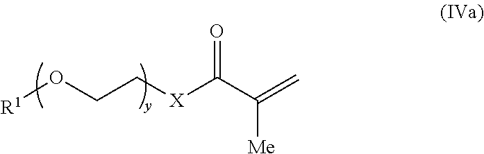
- the first methacrylate monomer has the structure of formula (IVa):
- X, y, R 1 , and R′ are selected to provide the first methacrylate-derived monomeric unit of the crosslinked, hydrophilic copolymer described herein.
- the first methacrylate monomer has the structure:
- the second methacrylate monomer has the structure of formula (V):
- Y, z, R 2 and R′ are selected to provide the second methacrylate-derived monomeric unit of the crosslinked, hydrophilic copolymer described herein.
- the second methacrylate monomer has the structure of formula (Va):
- x is selected to provide second methacrylate-derived monomeric units of the crosslinked, hydrophilic copolymer described herein where the poly(ethylene glycol) has a number average molecular weight (M n ) of about 100 to about 10,000.
- M n number average molecular weight
- x is selected to provide second methacrylate-derived monomeric units where the M n of the poly(ethylene glycol) falls within a range in Table 1.
- the second methacrylate monomer has the structure of formula (Va), where Y is —O—, R 2 is methyl and x is such that the poly(ethylene glycol) has a number average molecular weight (M n ) of about 500.
- the dimethacrylate monomer is a molecule having two terminal methacrylate groups tethered by a hydrophilic linker.
- the hydrophilic linker is selected to provide the crosslinks between third methacrylate-derived units in different backbone chains of the crosslinked, hydrophilic copolymer described herein.
- the dimethacrylate monomers can be the same, or in some instances, can be different.
- the extent of crosslinking in crosslinked, hydrophilic copolymer of the analyte sensor can be controlled by adjusting the amount of dimethacrylate monomer in the mixture.
- the dimethacrylate monomer is about 1% to about 15% of the mixture.
- the amount is about 1% to about 5%, or about 5% to about 10%, or about 10% to about 15%.
- the amount is about 1%.
- both the mixture includes about 1% of the dimethacrylate monomer.
- the dimethacrylate monomer includes one or more alkylene oxide units to provide the crosslinks of the crosslinked, hydrophilic copolymer as described herein.
- the dimethacrylate monomer includes poly(ethylene glycol) (PEG).
- PEG poly(ethylene glycol)
- the dimethacrylate monomer can have the structure of formula (VI):
- w 0, 1, 2, 3, 4, 5, 6, 7, 8, 9 or 10.
- w is an average value of from about 2 to about 250.
- the dimethacrylate monomer can have the structure of formula (VI) where w is such that the number average molecular weight (M n ) of the PEG portion of the dimethacrylate monomer is about 100 to about 10,000.
- w can be selected such that the M n of the PEG portion of the dimethacrylate monomer falls within a range in Table 2.
- the dimethacrylate monomer is di(ethylene glycol)dimethacrylate.
- Depositing the mixture onto a surface of an electrode can be accomplished by a number of methods.
- the depositing can be performed manually with a micro-syringe, or by automated fabrication processes with nano jet dispensing equipment.
- the amount of the mixture deposited onto a surface of an electrode is selected to provide the desired thickness of the crosslinked, hydrophilic copolymer of the analyte sensor.
- the amount deposited on the electrode is about 50 nL/mm 2 to about 500 nL/mm 2 .
- the amount is about 50 ⁇ m to about 150 ⁇ m, or about 150 ⁇ m to about 300 ⁇ m, or about 300 ⁇ m to about 500 ⁇ m in thickness.
- the amount is about 100 nL/mm 2 .
- depositing about 100 nL/mm 2 of the mixture provides a crosslinked, hydrophilic copolymer that is about 20 ⁇ m in thickness.
- Conditions suitable to initiate polymerization can be selected based on the characteristics of the initiator and the monomers being polymerized, and as so not to degrade the analyte sensing component.
- the analyte sensing component is an enzyme
- the temperature and pH of the method can be selected to preserve the activity of the enzyme.
- the initiator is activated with ultraviolet (UV) light.
- UV light For example, when 2,2-diemthoxy-2-phenylacetophenone is used as an initiator, curing can be performed with UV light.
- the initiators can be the same, or in some instances, can be different.
- a method for measuring the level of an analyte is a subject. The method includes:
- analyte sensor (a) mounting at least a portion of an analyte sensor onto the body of a subject, wherein the analyte sensor comprises:
- backbone chains comprising
- first and second side chains are the same or different
- the method employs a body-mountable device that includes an analyte sensor.
- a body-mountable device comprising an eye-mountable device that is configured to detect at least one analyte in a tear film of a user wearing the eye-mountable device will now be described in greater detail.
- FIG. 4 is a block diagram of a system 100 that includes an eye-mountable device 110 in wireless communication with an external reader 120 .
- the eye-mountable device 110 may be a polymeric material that may be appropriately shaped for mounting to a corneal surface and in which a structure is at least partially embedded.
- the structure may include a power supply 140 , a controller 150 , bio-interactive electronics 160 , and an antenna 170 .
- the structure may be a bio-compatible device in which some or all of the components formed or mounted thereon are encapsulated by a bio-compatible material.
- the structure may be positioned away from the center of the eye-mountable device 110 and thereby avoid interference with light transmission to the central, light-sensitive region of the eye.
- the structure may be embedded around the periphery (e.g., near the outer circumference) of the disk.
- the structure may be positioned in or near the central region of the eye-mountable device 110 .
- portions of the structure may be substantially transparent to incoming visible light to mitigate interference with light transmission to the eye.
- the bio-interactive electronics 160 may include a pixel array 164 that emits and/or transmits light to be received by the eye according to display instructions.
- the bio-interactive electronics 160 may optionally be positioned in the center of the eye-mountable device so as to generate visual cues perceivable to a wearer of the eye-mountable device 110 , such as displaying information (e.g., characters, symbols, flashing patterns, etc.) on the pixel array 164 .
- information e.g., characters, symbols, flashing patterns, etc.
- the power supply 140 is configured to harvest ambient energy to power the controller 150 and bio-interactive electronics 160 , and may include an energy harvesting antenna 142 and/or solar cells 144 .
- the energy harvesting antenna 142 may capture energy from incident radio radiation.
- the solar cells 144 may comprise photovoltaic cells configured to capture energy from incoming ultraviolet, visible, and/or infrared radiation.
- a rectifier/regulator 146 may be used to condition the captured energy to a stable DC supply voltage 141 at a level suitable for operating the controller, and then supply the voltage to the controller 150 .
- the rectifier/regulator 146 may include one or more energy storage devices to mitigate high frequency variations in the energy harvesting antenna 142 and/or solar cell(s) 144 .
- one or more energy storage devices e.g., a capacitor or an inductor
- the controller 150 is configured to execute instructions to operate the bio-interactive electronics 160 and the antenna 170 .
- the controller 150 includes logic circuitry configured to operate the bio-interactive electronics 160 so as to interact with a biological environment of the eye-mountable device 110 .
- the interaction could involve the use of one or more components, such an analyte bio-sensor 162 in the bio-interactive electronics 160 , to obtain input from the biological environment. Additionally or alternatively, the interaction could involve the use of one or more components, such as a pixel array 164 , to provide an output to the biological environment.
- the controller 150 includes a sensor interface module 152 that is configured to operate the analyte bio-sensor 162 .
- the analyte bio-sensor 162 may be, for example, an amperometric electrochemical sensor that includes a working electrode and a reference electrode driven by a sensor interface. A voltage is applied between the working and reference electrodes to cause an analyte to undergo an electrochemical reaction (e.g., a reduction and/or oxidation reaction) at the working electrode. The electrochemical reaction generates an amperometric current that can be measured through the working electrode. The amperometric current can be dependent on the analyte concentration. Thus, the amount of the amperometric current that is measured through the working electrode can provide an indication of analyte concentration.
- the sensor interface module 152 can be a potentiostat configured to apply a voltage difference between working and reference electrodes while measuring a current through the working electrode.
- a reagent may also be included to sensitize the electrochemical sensor to one or more desired analytes.
- a layer of glucose oxidase (“GOD”) proximal to the working electrode can catalyze glucose oxidation to generate hydrogen peroxide (H 2 O 2 ).
- the hydrogen peroxide can then be electro-oxidized at the working electrode, which releases electrons to the working electrode, resulting in an amperometric current that can be measured through the working electrode as discussed above.
- the current generated by either reduction or oxidation reactions is approximately proportionate to the reaction rate. Further, the reaction rate is dependent on the rate of analyte molecules reaching the electrochemical sensor electrodes to fuel the reduction or oxidation reactions, either directly or catalytically through a reagent. In a steady state, where analyte molecules diffuse to the electrochemical sensor electrodes from a sampled region at approximately the same rate that additional analyte molecules diffuse to the sampled region from surrounding regions, the reaction rate is approximately proportionate to the concentration of the analyte molecules. The current measured through the working electrode thus provides an indication of the analyte concentration.
- the controller 150 may also include a display driver module 154 for operating a pixel array 164 .
- the pixel array 164 is an array of separately programmable light transmitting, light reflecting, and/or light emitting pixels arranged in rows and columns.
- the individual pixel circuits can optionally include liquid crystal technologies, microelectromechanical technologies, emissive diode technologies, etc. to selectively transmit, reflect, and/or emit light according to information from the display driver module 154 .
- Such a pixel array 164 may also include more than one color of pixels (e.g., red, green, and blue pixels) to render visual content in color.
- the display driver module 154 can include, for example, one or more data lines providing programming information to the separately programmed pixels in the pixel array 164 and one or more addressing lines for setting groups of pixels to receive such programming information.
- a pixel array 164 situated on the eye can also include one or more lenses to direct light from the pixel array to a focal plane perceivable by the eye.
- the controller 150 may also include a communication circuit 156 for sending and/or receiving information via the antenna 170 .
- the communication circuit 156 may include one or more oscillators, mixers, frequency injectors, or the like to modulate and/or demodulate information on a carrier frequency to be transmitted and/or received by the antenna 170 .
- the eye-mountable device 110 is configured to indicate an output from a bio-sensor by modulating an impedance of the antenna 170 in a manner that is perceivable by the external reader 120 .
- the communication circuit 156 can cause variations in the amplitude, phase, and/or frequency of backscatter radiation from the antenna 170 , and such variations may then be detected by the reader 120 .
- the controller 150 is connected to the bio-interactive electronics 160 via interconnects 151 . Similarly, the controller 150 is connected to the antenna 170 via interconnects 157 .
- the interconnects 151 , 157 may comprise a patterned conductive material (e.g., gold, platinum, palladium, titanium, copper, aluminum, silver, metals, any combinations of these, etc.).
- FIG. 4 the block diagram shown in FIG. 4 is described in connection with functional modules for convenience in description.
- embodiments of the eye-mountable device 110 can be arranged with one or more of the functional modules (“sub-systems”) implemented in a single chip, integrated circuit, and/or physical component.
- the energy harvesting antenna 142 and the antenna 170 can be implemented in the same, dual-purpose antenna.
- a loop antenna can both harvest incident radiation for power generation and communicate information via backscatter radiation.
- the external reader 120 includes an antenna 128 (or group of more than one antennae) to send and receive wireless signals 171 to and from the eye-mountable device 110 .
- the external reader 120 also includes a computing system with a processor 126 in communication with a memory 122 .
- the memory 122 is a non-transitory computer-readable medium that can include, without limitation, magnetic disks, optical disks, organic memory, and/or any other volatile (e.g., RAM) or non-volatile (e.g., ROM) storage system readable by the processor 126 .
- the memory 122 includes a data storage 123 to store indications of data, such as sensor readings (e.g., from the analyte bio-sensor 162 ), program settings (e.g., to adjust behavior of the eye-mountable device 110 and/or external reader 120 ), etc.
- the memory 122 also includes program instructions 124 for execution by the processor 126 .
- the program instructions 124 may cause the external reader 120 to provide a user interface that allows for retrieving information communicated from the eye-mountable device 110 (e.g., sensor outputs from the analyte bio-sensor 162 ).
- the external reader 120 may also include one or more hardware components for operating the antenna 128 to send and receive the wireless signals 171 to and from the eye-mountable device 110 . For example, oscillators, frequency injectors, encoders, decoders, amplifiers, and filters can drive the antenna 128 according to instructions from the processor 126 .
- the external reader 120 may be a smart phone, digital assistant, or other portable computing device with wireless connectivity sufficient to provide the wireless communication link 171 .
- the external reader 120 may also be implemented as an antenna module that can be plugged in to a portable computing device, such as in an example where the communication link 171 operates at carrier frequencies not commonly employed in portable computing devices.
- the external reader 120 is a special-purpose device configured to be worn relatively near a wearer's eye to allow the wireless communication link 171 to operate using little or low power.
- the external reader 120 can be integrated in a piece of jewelry such as a necklace, earring, etc. or integrated in an article of clothing worn near the head, such as a hat, headband, etc.
- the system 100 can be operated to monitor the analyte concentration in tear film on the surface of the eye.
- the external reader 120 can emit radio frequency radiation 171 that is harvested to power the eye-mountable device 110 via the power supply 140 .
- Radio frequency electrical signals captured by the energy harvesting antenna 142 (and/or the antenna 170 ) are rectified and/or regulated in the rectifier/regulator 146 and a regulated DC supply voltage 141 is provided to the controller 150 .
- the radio frequency radiation 171 thus turns on the electronic components within the eye-mountable device 110 .
- the controller 150 operates the analyte bio-sensor 162 to measure an analyte concentration level.
- the sensor interface module 152 can apply a voltage between a working electrode and a reference electrode in the analyte bio-sensor 162 .
- the applied voltage can be sufficient to cause the analyte to undergo an electrochemical reaction at the working electrode and thereby generate an amperometric current that can be measured through the working electrode.
- the measured amperometric current can provide the sensor reading (“result”) indicative of the analyte concentration.
- the controller 150 can operate the antenna 170 to communicate the sensor reading back to the external reader 120 (e.g., via the communication circuit 156 ).
- the system 100 can operate to non-continuously (“intermittently”) supply energy to the eye-mountable device 110 to power the controller 150 and electronics 160 .
- radio frequency radiation 171 can be supplied to power the eye-mountable device 110 long enough to carry out a tear film analyte concentration measurement and communicate the results.
- the supplied radio frequency radiation can provide sufficient power to apply a potential between a working electrode and a reference electrode sufficient to induce electrochemical reactions at the working electrode, measure the resulting amperometric current, and modulate the antenna impedance to adjust the backscatter radiation in a manner indicative of the measured amperometric current.
- the supplied radio frequency radiation 171 can be considered an interrogation signal from the external reader 120 to the eye-mountable device 110 to request a measurement.
- the external reader 120 can accumulate a set of analyte concentration measurements over time without continuously powering the eye-mountable device 110 .
- FIG. 5 a is a top view of an eye-mountable device 210 .
- FIG. 5 b is side view of the eye-mountable device 210 . It is noted that relative dimensions in FIGS. 5 a and 5 b are not necessarily to scale, but have been rendered for purposes of explanation only in describing the arrangement of the eye-mountable device 210 .
- the eye-mountable device 210 may include a polymeric material 220 , which may be a substantially transparent material to allow incident light to be transmitted to the eye.
- the polymeric material 220 may include one or more bio-compatible materials similar to those employed to form vision correction and/or cosmetic contact lenses in optometry, such as polyethylene terephthalate (“PET”), polymethyl methacrylate (“PMMA”), polyhydroxyethylmethacrylate (“polyHEMA”), silicone hydrogels, or any combinations of these. Other polymeric materials may also be envisioned.
- the polymeric material 220 may include materials configured to moisturize the corneal surface, such as hydrogels and the like. In some embodiments, the polymeric material 220 is a deformable (“non-rigid”) material to enhance wearer comfort.
- the eye-mountable device 210 may comprise a concave surface 226 configured to adhere (“mount”) to a moistened corneal surface (e.g., by capillary forces with a tear film coating the corneal surface). While mounted with the concave surface against the eye, a convex surface 224 of eye-mountable device 210 is formed so as not to interfere with eye-lid motion while the eye-mountable device 210 is mounted to the eye.
- a circular outer side edge 228 connects the concave surface 224 and the convex surface 226 .
- the convex surface 224 can therefore be considered an outer, top surface of the eye-mountable device 210 whereas the concave surface 226 can be considered an inner, bottom surface.
- the “top” view shown in FIG. 5 a is facing the convex surface 224 .
- the eye-mountable device 210 can have dimensions similar to a vision correction and/or cosmetic contact lenses, such as a diameter of approximately 1 centimeter, and a thickness of about 0.1 to about 0.5 millimeters. However, the diameter and thickness values are provided for explanatory purposes only. In some embodiments, the dimensions of the eye-mountable device 210 may be selected according to the size and/or shape of the corneal surface and/or the scleral surface of the wearer's eye. In some embodiments, the eye-mountable device 210 is shaped to provide a predetermined, vision-correcting optical power, such as provided by a prescription contact lens.
- a structure 230 is embedded in the eye-mountable device 210 .
- the structure 230 can be embedded to be situated near or along an outer periphery 222 , away from a central region 221 . Such a position ensures that the structure 230 will not interfere with a wearer's vision when the eye-mountable device 210 is mounted on a wearer's eye, because it is positioned away from the central region 221 where incident light is transmitted to the light-sensing portions of the eye.
- portions of the structure 230 can be formed of a transparent material to further mitigate effects on visual perception.
- the structure 230 may be shaped as a flat, circular ring (e.g., a disk with a centered hole).
- the flat surface of the structure 230 (e.g., along the radial width) allows for mounting electronics such as chips (e.g., via flip-chip mounting) and for patterning conductive materials to form electrodes, antenna(e), and/or interconnections.
- the structure 230 and the polymeric material 220 may be approximately cylindrically symmetric about a common central axis.
- the structure 230 may have, for example, a diameter of about 10 millimeters, a radial width of about 1 millimeter (e.g., an outer radius 1 millimeter greater than an inner radius), and a thickness of about 50 micrometers. These dimensions are provided for example purposes only, and in no way limit this disclosure.
- a loop antenna 270 , controller 250 , and bio-interactive electronics 260 are included in the structure 230 .
- the controller 250 may be a chip including logic elements configured to operate the bio-interactive electronics 260 and the loop antenna 270 .
- the controller 250 is electrically connected to the loop antenna 270 by interconnects 257 also situated on the structure 230 .
- the controller 250 is electrically connected to the bio-interactive electronics 260 by an interconnect 251 .
- the interconnects 251 , 257 , the loop antenna 270 , and any conductive electrodes may be formed from any type of conductive material and may be patterned by any process that can be used for patterning such materials, such as deposition or photolithography, for example.
- the conductive materials patterned on the structure 230 may be, for example, gold, platinum, palladium, titanium, carbon, aluminum, copper, silver, silver-chloride, conductors formed from noble materials, metals, or any combinations of these materials. Other materials may also be envisioned.
- the structure 230 may be a bio-compatible device in which some or all of the components are encapsulated by a bio-compatible material.
- the controller 250 , interconnects 251 , 257 , bio-interactive electronics 260 , and the loop antenna 270 are fully encapsulated by bio-compatible material, except for the sensor electrodes in the bio-interactive electronics 260 .
- the bio-interactive electronics module 260 is on a side of the structure 230 facing the convex surface 224 .
- the bio-interactive electronics module 260 includes an analyte bio-sensor, for example, mounting such a bio-sensor on the structure 230 to be close to the convex surface 224 allows the bio-sensor to sense analyte that has diffused through convex surface 224 or has reached the bio-sensor through a channel in the convex surface 224 ( FIGS. 5 c and 5 d show a channel 272 ).
- the loop antenna 270 is a layer of conductive material patterned along the flat surface of the structure 230 to form a flat conductive ring.
- the loop antenna 270 does not form a complete loop.
- the loop antenna 270 may include a cutout to allow room for the controller 250 and bio-interactive electronics 260 , as illustrated in FIG. 5 a .
- the loop antenna 270 can be arranged as a continuous strip of conductive material that wraps entirely around the structure 230 one or more times. Interconnects between the ends of such a wound antenna (e.g., the antenna leads) can connect to the controller 250 in the structure 230 .
- the loop antenna can include a plurality of conductive loops spaced apart from each other, such as three conductive loops, five conductive loops, nine conductive loops, etc. With such an arrangement, the polymeric material 220 may extend between adjacent conductive loops in the plurality of conductive loops.
- FIG. 5 c is a side cross-section view of the eye-mountable electronic device 210 mounted to a corneal surface 284 of an eye 280 .
- FIG. 5 d is an enlarged partial view of the cross-section of the eye-mountable device shown in FIG. 5 c . It is noted that relative dimensions in FIGS. 5 c and 5 d are not necessarily to scale, but have been rendered for purposes of explanation only in describing the arrangement of the eye-mountable device 210 . Some aspects are exaggerated to allow for illustration and to facilitate explanation.
- the eye 280 includes a cornea 282 that is covered by bringing an upper eyelid 286 and a lower eyelid 288 together over the surface of the eye 280 .
- Incident light is received by the eye 280 through the cornea 282 , where light is optically directed to light sensing elements of the eye 280 to stimulate visual perception.
- the motion of the upper and lower eyelids 286 , 288 distributes a tear film across the exposed corneal surface 284 of the eye 280 .
- the tear film is an aqueous solution secreted by the lacrimal gland to protect and lubricate the eye 280 .
- the tear film coats both the concave and convex surfaces 224 , 226 , providing an inner layer 290 (along the concave surface 226 ) and an outer layer 292 (along the convex surface 224 ).
- the inner layer 290 on the corneal surface 284 also facilitates mounting the eye-mountable device 210 by capillary forces between the concave surface 226 and the corneal surface 284 .
- the eye-mountable device 210 can also be held over the eye 280 in part by vacuum forces against the corneal surface 284 due to the curvature of the concave surface 226 .
- the tear film layers 290 , 292 may be about 10 micrometers in thickness and together account for about 10 microliters of fluid.
- the tear film is in contact with the blood supply through capillaries in the structure of the eye and includes many biomarkers found in blood that are analyzed to diagnose health states of an individual.
- tear film includes glucose, calcium, sodium, cholesterol, potassium, other biomarkers, etc.
- the biomarker concentrations in tear film can be systematically different than the corresponding concentrations of the biomarkers in the blood, but a relationship between the two concentration levels can be established to map tear film biomarker concentration values to blood concentration levels.
- the tear film concentration of glucose can be established (e.g., empirically determined) to be approximately one tenth the corresponding blood glucose concentration.
- another ratio relationship and/or a non-ratio relationship may be used.
- measuring tear film analyte concentration levels provides a non-invasive technique for monitoring biomarker levels in comparison to blood sampling techniques performed by lancing a volume of blood to be analyzed outside a person's body.
- the structure 230 can be inclined so as to be approximately parallel to the adjacent portion of the convex surface 224 .
- the structure 230 is a flattened ring with an inward-facing surface 232 (closer to the concave surface 226 of the polymeric material 220 ) and an outward-facing surface 234 (closer to the convex surface 224 ).
- the structure 230 can include electronic components and/or patterned conductive materials adjacent to either or both surfaces 232 , 234 .
- the bio-interactive electronics 260 , the controller 250 , and the conductive interconnect 251 are located between the outward-facing surface 234 and the inward-facing surface 632 such that the bio-interactive electronics 260 are facing the convex surface 224 .
- the bio-interactive electronics 260 can receive analyte concentrations in the tear film 292 through the channel 272 .
- the bio-interactive electronics 260 may be mounted on the inward-facing surface 232 of the structure 230 such that the bio-interactive electronics 260 are facing the concave surface 226 .
- body-mountable device has been described as comprising the eye-mountable device 110 and/or the eye-mountable device 210 , the body-mountable device could comprise other mountable devices that are mounted on or in other portions of the human body.
- the body-mountable device may comprise a tooth-mountable device.
- the tooth-mountable device may take the form of or be similar in form to the eye-mountable device 110 and/or the eye-mountable device 210 .
- the tooth-mountable device could include a polymeric material that is the same as or similar to any of the polymeric materials described herein and a structure that is the same as or similar to any of the structures described herein.
- the tooth-mountable device may be configured to detect at least one analyte in a fluid (e.g., saliva) of a user wearing the tooth-mountable device.
- the body-mountable device may comprise a skin-mountable device.
- the skin-mountable device may take the form of or be similar in form to the eye-mountable device 110 and/or the eye-mountable device 210 .
- the skin-mountable device could include a polymeric material that is the same as or similar to any of the polymeric materials described herein and a structure that is the same as or similar to any of the structures described herein.
- the skin-mountable device may be configured to detect at least one analyte in a fluid (e.g., perspiration, blood, etc.) of a user wearing the skin-mountable device.
- a fluid e.g., perspiration, blood, etc.
- some embodiments may include privacy controls which may be automatically implemented or controlled by the wearer of a body-mountable device. For example, where a wearer's collected physiological parameter data and health state data are uploaded to a cloud computing network for trend analysis by a clinician, the data may be treated in one or more ways before it is stored or used, so that personally identifiable information is removed. For example, a user's identity may be treated so that no personally identifiable information can be determined for the user, or a user's geographic location may be generalized where location information is obtained (such as to a city, ZIP code, or state level), so that a particular location of a user cannot be determined.
- wearers of a body-mountable device may be provided with an opportunity to control whether or how the device collects information about the wearer (e.g., information about a user's medical history, social actions or activities, profession, a user's preferences, or a user's current location), or to control how such information may be used.
- the wearer may have control over how information is collected about him or her and used by a clinician or physician or other user of the data.
- a wearer may elect that data, such as health state and physiological parameters, collected from his or her device may only be used for generating an individual baseline and recommendations in response to collection and comparison of his or her own data and may not be used in generating a population baseline or for use in population correlation studies.
- the resulting formulations were thoroughly mixed with a vortex shaker. A micro-syringe was used to deposit 100 nL/mm 2 of each formulation onto a sensor electrode, and the deposited solution was UV-cured for 5 minutes at 365 nm under nitrogen with an EC-500 light exposure chamber (Electro-Lite Corp). The resulting cured crosslinked copolymers each had a thickness of about 20 ⁇ m.
- the sensor made with Formulation F4 used a greater ratio of solution C to solution B than Formulation F2.
- the sensor made with Formulation F4 has a greater ratio of poly(ethylene glycol) methyl ether methacrylate-derived units to 2-hydroxyethyl methacrylate-derived units than the sensor made with Formulation F2.
- the analyte sensors of Formulation F2 and F4 formed in Example 1 were tested at concentrations of glucose in phosphate buffered saline (PBS) ranging from 50 ⁇ M to 1000 ⁇ m. Both sensors were submerged in PBS and the glucose concentration was increased every 10-15 minutes. The current generated at the electrode was measured using a potentiostat. A linear relationship between current and glucose concentration was observed for both formulations (See inset, FIG. 1 ).
- the sensor made with Formulation F4 which was a greater ratio of poly(ethylene glycol) methyl ether methacrylate-derived units to 2-hydroxyethyl methacrylate-derived units than the sensor made with Formulation F2, had a higher current response at the same concentration of glucose than the sensor made with Formulation F2. See FIG. 1 .
- Example 3 essentially Example 3 was repeated with a wider temperature range.
- Seven analyte sensors of Formula F1 were prepared in accordance with the procedure of Example 1 and were tested in 1 mM glucose solution in PBS at various temperatures. As shown in FIG. 3 , when current was measured for 1.0 mM glucose concentration at increasing temperatures 24, 29, 34 and 39 degrees Celsius, the temperature effect on the current response was again minimal or negligible ( ⁇ 1% per degree Celsius), demonstrating the temperature insensitivity of the analyte sensor.
- crosslinked, hydrophilic copolymers in the above examples comprise methacrylate groups, there are a number of ethylenically unsaturated groups known in the art to be capable of undergoing polymerization.
- Ethylenically unsaturated monomers and macromers may be either acrylic- or vinyl-containing Vinyl-containing monomers contain the vinyl grouping (CH 2 ⁇ CH—), and are generally highly reactive.
- Acrylic-containing monomers are represented by the formula:
- suitable polymerizable groups may include acrylic-, ethacrylic-, itaconic-, styryl-, acrylamido-, methacrylamido- and vinyl-containing groups such as the allyl group.
- crosslinked, hydrophilic copolymers In addition to the above disclosed methods of forming crosslinked, hydrophilic copolymers by the polymerization of ethylenically unsaturated monomers and macromonomers, additional chemistries will be known to one or ordinary skill in the art to from such copolymers.
- epoxy chemistry in which multifunctional amines and multifunctional epoxy compounds are mixed together and cured, can be used to form crosslinked, hydrophilic copolymers.
- urethane chemistry may be used, in which multifunctional isocyanates are mixed with multifunctional alcohols and cured to provide crosslinked, hydrophilic copolymers.
- Other chemistries for the formation of crosslinked, hydrophilic copolymers exist, and will be well known to those of ordinary skill in the art.
Abstract
Description
-
- backbone chains having
- first methacrylate-derived units, each having a first hydrophilic side chain;
- second methacrylate-derived units, each having a second hydrophilic side chain,
- where the first and second side chains are the same or different;
- third methacrylate-derived units; and
- hydrophilic crosslinks between third methacrylate-derived units in different backbone chains, wherein the crosslinked, hydrophilic copolymer has an analyte permeability that is substantially temperature independent and wherein the analyte sensor generates signals that are substantially temperature independent over a range of temperatures.
- backbone chains having

where R is a hydrophilic group. In certain embodiments, the hydrophilic group includes one or more hydroxy groups, such as an alcohol.

where X is —O—, —NR′— or —S—, y is 0, 1, 2, 3, 4, 5, 6, 7, 8, 9 or 10, and R1 is hydrogen, —C1-C12alkyl, —C1-C12alkyl-OH, —SiR′3, —C(O)—C1-C12alkyl, —C1-C12alkyl-C(O)OR′, where R′ is —C1-C12alkyl.


where Y and R2 are as described above and x is such that the poly(ethylene glycol) has a number average molecular weight (Mn) of about 100 to about 10,000. In certain embodiments, x is selected so that the Mn of the poly(ethylene glycol) falls within a range in Table 1.
| TABLE 1 |
| Mn range of poly(ethylene glycol) in the second methacrylate- |
| derived units (values are approximate). |
| | High | ||
| 100 | 200 | ||
| 200 | 300 | ||
| 300 | 400 | ||
| 400 | 500 | ||
| 500 | 600 | ||
| 600 | 700 | ||
| 700 | 800 | ||
| 800 | 900 | ||
| 900 | 1,000 | ||
| 1,000 | 2,000 | ||
| 2,000 | 3,000 | ||
| 3,000 | 4,000 | ||
| 4,000 | 5,000 | ||
| 5,000 | 6,000 | ||
| 7,000 | 8,000 | ||
| 8,000 | 9,000 | ||
| 9,000 | 10,000 | ||


where X′ is independently —O—, —NR′— or —S—, and A is a hydrophilic group.

where w is 0, 1, 2, 3, 4, 5, 6, 7, 8, 9 or 10.
| TABLE 2 |
| Mn range of the PEG portion of the crosslinks |
| (values are approximate). |
| | High | ||
| 100 | 200 | ||
| 200 | 300 | ||
| 300 | 400 | ||
| 400 | 500 | ||
| 500 | 600 | ||
| 600 | 700 | ||
| 700 | 800 | ||
| 800 | 900 | ||
| 900 | 1,000 | ||
| 1,000 | 2,000 | ||
| 2,000 | 3,000 | ||
| 3,000 | 4,000 | ||
| 4,000 | 5,000 | ||
| 5,000 | 6,000 | ||
| 7,000 | 8,000 | ||
| 8,000 | 9,000 | ||
| 9,000 | 10,000 | ||

where R is a hydrophilic group. In certain embodiments of the method, the hydrophilic group includes one or more hydroxy groups, such as an alcohol.
where X, y, R1, and R′ are selected to provide the first methacrylate-derived monomeric unit of the crosslinked, hydrophilic copolymer described herein.


where w is 0, 1, 2, 3, 4, 5, 6, 7, 8, 9 or 10.
-
- first methacrylate-derived units, each having a first hydrophilic side chain;
- second methacrylate-derived units, each having a second hydrophilic side chain,
-
- third methacrylate-derived units; and
- hydrophilic crosslinks between third methacrylate-derived units in different backbone chains,
-
- A) 25 mg/ml glucose oxidase (GOx) in PBS buffer (pH=7.4)
- B) 2-hydroxyethyl methacrylate monomer solution containing 1% by weight di(ethylene glycol)dimethacrylate and 1% by
weight 2,2-dimethoxy-2-phenylacetophenone. - C) poly(ethylene glycol) methyl ether methacrylate (
average Mn 500, Aldrich product #447943) monomer solution containing 1% by weight di(ethylene glycol)dimethacrylate and 1% byweight 2,2-dimethoxy-2-phenylacetophenone.
| A | B | C | ||
| Formulation F2 | 0.40 | 0.40 | 0.20 | ||
| Formulation F4 | 0.40 | 0.35 | 0.25 | ||

Claims (13)


Priority Applications (6)
| Application Number | Priority Date | Filing Date | Title |
|---|---|---|---|
| US14/098,806 US9617578B2 (en) | 2013-12-06 | 2013-12-06 | Sensor membrane with low temperature coefficient |
| PCT/US2014/065905 WO2015084570A1 (en) | 2013-12-06 | 2014-11-17 | Sensor membrane with low temperature coefficient |
| JP2016536573A JP6174809B2 (en) | 2013-12-06 | 2014-11-17 | Sensor membrane with low temperature coefficient |
| CN201480065950.0A CN105960591A (en) | 2013-12-06 | 2014-11-17 | Sensor membrane with low temperature coefficient |
| RU2016126203A RU2641966C2 (en) | 2013-12-06 | 2014-11-17 | Sensor membrane with low temperature coefficient |
| EP14867505.1A EP3077805A4 (en) | 2013-12-06 | 2014-11-17 | Sensor membrane with low temperature coefficient |
Applications Claiming Priority (1)
| Application Number | Priority Date | Filing Date | Title |
|---|---|---|---|
| US14/098,806 US9617578B2 (en) | 2013-12-06 | 2013-12-06 | Sensor membrane with low temperature coefficient |
Publications (2)
| Publication Number | Publication Date |
|---|---|
| US20150159190A1 US20150159190A1 (en) | 2015-06-11 |
| US9617578B2 true US9617578B2 (en) | 2017-04-11 |
Family
ID=53270546
Family Applications (1)
| Application Number | Title | Priority Date | Filing Date |
|---|---|---|---|
| US14/098,806 Expired - Fee Related US9617578B2 (en) | 2013-12-06 | 2013-12-06 | Sensor membrane with low temperature coefficient |
Country Status (6)
| Country | Link |
|---|---|
| US (1) | US9617578B2 (en) |
| EP (1) | EP3077805A4 (en) |
| JP (1) | JP6174809B2 (en) |
| CN (1) | CN105960591A (en) |
| RU (1) | RU2641966C2 (en) |
| WO (1) | WO2015084570A1 (en) |
Families Citing this family (5)
| Publication number | Priority date | Publication date | Assignee | Title |
|---|---|---|---|---|
| US9085790B2 (en) * | 2010-07-28 | 2015-07-21 | Abbott Diabetes Care Inc. | Analyte sensors having temperature independent membranes |
| US9696564B1 (en) | 2012-08-21 | 2017-07-04 | Verily Life Sciences Llc | Contact lens with metal portion and polymer layer having indentations |
| US9834805B2 (en) | 2013-12-23 | 2017-12-05 | Verily Life Sciences Llc | Two-layer analyte sensor |
| US9690118B2 (en) * | 2014-06-13 | 2017-06-27 | Verily Life Sciences Llc | Eye-mountable device to provide automatic accommodation and method of making same |
| CN114609213A (en) * | 2022-03-17 | 2022-06-10 | 苏州中星医疗技术有限公司 | Glucose sensor and preparation method and application thereof |
Citations (35)
| Publication number | Priority date | Publication date | Assignee | Title |
|---|---|---|---|---|
| US5102552A (en) | 1987-12-16 | 1992-04-07 | Hoechst Celanese Corporation | Membranes from UV-curable resins |
| WO1993022039A1 (en) | 1992-04-24 | 1993-11-11 | Gelman Sciences Inc. | Hydrophilic microporous polyolefin membrane |
| US5928918A (en) | 1994-10-05 | 1999-07-27 | Avl Medical Instruments Ag | Preparation of a hydrophobic polymer matrix containing immobilized enzymes |
| US5985129A (en) | 1989-12-14 | 1999-11-16 | The Regents Of The University Of California | Method for increasing the service life of an implantable sensor |
| US6653358B2 (en) | 1998-11-24 | 2003-11-25 | Dow Global Technologies Inc. | Composition containing a cross-linkable matrix precursor and a poragen, and a porous matrix prepared therefrom |
| US20040185568A1 (en) | 2003-01-31 | 2004-09-23 | Tanita Corporation | Sensor storage solution, sensor calibration solution and sensor |
| US20050118204A1 (en) * | 2003-09-25 | 2005-06-02 | Kazutami Sakamoto | Methods for controlling membrane permeability of a membrane permeable substance and screening methods for a membrane permeable substance |
| US6927246B2 (en) | 2001-02-15 | 2005-08-09 | Medtronic Minimed, Inc. | Polymers functionalized with fluorescent boronate motifs and methods for making them |
| JP2005315871A (en) | 2004-03-31 | 2005-11-10 | Terumo Corp | Intracorporeal substance measuring assembly, manufacturing method for intracorporeal substance measuring assembly, and embedded type substance sensor |
| WO2005114720A2 (en) | 2004-05-14 | 2005-12-01 | California Institute Of Technology | Parylene-based flexible multi-electrode arrays for neuronal stimulation and recording and methods for manufacturing the same |
| US20070244379A1 (en) | 2002-05-22 | 2007-10-18 | Robert Boock | Silicone based membranes for use in implantable glucose sensors |
| US20080223732A1 (en) | 2003-01-20 | 2008-09-18 | Universal Biosensors Pty Ltd. | Electrochemical detection method |
| US20080241892A1 (en) | 2007-03-29 | 2008-10-02 | Pacific Biosciences Of California, Inc. | Modified surfaces for immobilization of active molecules |
| US7450980B2 (en) | 2004-03-31 | 2008-11-11 | Terumo Kabushiki Kaisha | Intracorporeal substance measuring assembly |
| US20100096277A1 (en) | 2007-03-21 | 2010-04-22 | Universiti Putra Malaysia | Amperometric biosensor for histamine determination |
| WO2010057095A2 (en) | 2008-11-14 | 2010-05-20 | The Regents Of The University Of Michigan | Method for manufacturing an implantable electronic device |
| US7731835B2 (en) | 1999-09-20 | 2010-06-08 | Roche Diagnostics Operations, Inc. | Electrochemical sensor and method for continuous analyte monitoring |
| US20110136929A1 (en) | 2008-07-09 | 2011-06-09 | Pei Yong Edwin Chow | Trapping glucose probe in pores of polymer |
| US20110152654A1 (en) | 2009-12-21 | 2011-06-23 | Medtronic Minimed, Inc. | Analyte sensors comprising blended membrane compositions and methods for making and using them |
| US20110308944A1 (en) | 2009-02-09 | 2011-12-22 | Arkray, Inc. | Electrochemical Sensor and Method for Manufacturing Same |
| US20120028283A1 (en) | 2010-07-28 | 2012-02-02 | Abott Diabetes Care Inc. | Analyte Sensors Having Temperature Independent Membranes |
| US20120088997A1 (en) | 2010-10-12 | 2012-04-12 | Anthony Guiseppi-Elie | Implantable biochip for managing trauma--induced hemorrhage |
| US8224414B2 (en) | 2004-10-28 | 2012-07-17 | Echo Therapeutics, Inc. | System and method for analyte sampling and analysis with hydrogel |
| US20120186997A1 (en) * | 2011-01-20 | 2012-07-26 | Medtronic Minimed, Inc. | Layered enzyme compositions for use with analyte sensors |
| WO2012115501A1 (en) | 2011-02-22 | 2012-08-30 | Mimos Berhad | Protective coating for biosensor membrane and method of forming said coating |
| US8268637B2 (en) | 2008-01-11 | 2012-09-18 | The Board Of Trustees Of The University Of Illinois | Label-free biosensors based upon distributed feedback laser |
| US8274021B2 (en) | 2008-03-07 | 2012-09-25 | California Institute Of Technology | Fully integrated temperature regulator for biochemical applications |
| US20120245444A1 (en) | 2007-11-07 | 2012-09-27 | University Of Washington | Wireless powered contact lens with glucose sensor |
| US20130011460A1 (en) | 2011-07-08 | 2013-01-10 | Dean-Mo Liu | Drug-carrying contact lens and method for fabricating the same |
| US8385998B2 (en) | 2008-10-24 | 2013-02-26 | Jin Zhang | Contact lens integrated with a biosensor for the detection of glucose and other components in tears |
| US20130084649A1 (en) | 2010-02-19 | 2013-04-04 | Lightship Medical Limited | Fluorescence measurement |
| US8437829B2 (en) | 2001-05-15 | 2013-05-07 | Abbott Diabetes Care Inc. | Biosensor membranes |
| US8473222B2 (en) | 2010-03-11 | 2013-06-25 | Glumetrics, Inc. | Measurement devices and methods for measuring analyte concentration incorporating temperature and pH correction |
| US8542024B2 (en) | 2010-12-23 | 2013-09-24 | General Electric Company | Temperature-independent chemical and biological sensors |
| US20130267802A1 (en) | 2009-11-04 | 2013-10-10 | Glumetrics, Inc. | Optical sensor configuration for ratiometric correction of blood glucose measurement |
Family Cites Families (5)
| Publication number | Priority date | Publication date | Assignee | Title |
|---|---|---|---|---|
| US7162289B2 (en) * | 2002-09-27 | 2007-01-09 | Medtronic Minimed, Inc. | Method and apparatus for enhancing the integrity of an implantable sensor device |
| US7888061B2 (en) * | 2005-05-17 | 2011-02-15 | Radiometer Medical Aps | Method of stabilising or reactivating a creatinine sensor with a divalent manganese ion |
| US8812071B2 (en) * | 2007-03-07 | 2014-08-19 | Echo Therapeutics, Inc. | Transdermal analyte monitoring systems and methods for analyte detection |
| US8364218B2 (en) * | 2008-02-11 | 2013-01-29 | Glucovista, Inc. | Apparatus and method for non-invasive measurement of the concentration of a substance in subjects blood |
| US20110082356A1 (en) * | 2009-10-01 | 2011-04-07 | Medtronic Minimed, Inc. | Analyte sensor apparatuses having interference rejection membranes and methods for making and using them |
-
2013
- 2013-12-06 US US14/098,806 patent/US9617578B2/en not_active Expired - Fee Related
-
2014
- 2014-11-17 WO PCT/US2014/065905 patent/WO2015084570A1/en active Application Filing
- 2014-11-17 EP EP14867505.1A patent/EP3077805A4/en not_active Withdrawn
- 2014-11-17 JP JP2016536573A patent/JP6174809B2/en not_active Expired - Fee Related
- 2014-11-17 CN CN201480065950.0A patent/CN105960591A/en active Pending
- 2014-11-17 RU RU2016126203A patent/RU2641966C2/en not_active IP Right Cessation
Patent Citations (36)
| Publication number | Priority date | Publication date | Assignee | Title |
|---|---|---|---|---|
| US5102552A (en) | 1987-12-16 | 1992-04-07 | Hoechst Celanese Corporation | Membranes from UV-curable resins |
| US5985129A (en) | 1989-12-14 | 1999-11-16 | The Regents Of The University Of California | Method for increasing the service life of an implantable sensor |
| WO1993022039A1 (en) | 1992-04-24 | 1993-11-11 | Gelman Sciences Inc. | Hydrophilic microporous polyolefin membrane |
| US5928918A (en) | 1994-10-05 | 1999-07-27 | Avl Medical Instruments Ag | Preparation of a hydrophobic polymer matrix containing immobilized enzymes |
| US6653358B2 (en) | 1998-11-24 | 2003-11-25 | Dow Global Technologies Inc. | Composition containing a cross-linkable matrix precursor and a poragen, and a porous matrix prepared therefrom |
| US7731835B2 (en) | 1999-09-20 | 2010-06-08 | Roche Diagnostics Operations, Inc. | Electrochemical sensor and method for continuous analyte monitoring |
| US6927246B2 (en) | 2001-02-15 | 2005-08-09 | Medtronic Minimed, Inc. | Polymers functionalized with fluorescent boronate motifs and methods for making them |
| US8437829B2 (en) | 2001-05-15 | 2013-05-07 | Abbott Diabetes Care Inc. | Biosensor membranes |
| US20070244379A1 (en) | 2002-05-22 | 2007-10-18 | Robert Boock | Silicone based membranes for use in implantable glucose sensors |
| US20080223732A1 (en) | 2003-01-20 | 2008-09-18 | Universal Biosensors Pty Ltd. | Electrochemical detection method |
| US20040185568A1 (en) | 2003-01-31 | 2004-09-23 | Tanita Corporation | Sensor storage solution, sensor calibration solution and sensor |
| US20050118204A1 (en) * | 2003-09-25 | 2005-06-02 | Kazutami Sakamoto | Methods for controlling membrane permeability of a membrane permeable substance and screening methods for a membrane permeable substance |
| US7450980B2 (en) | 2004-03-31 | 2008-11-11 | Terumo Kabushiki Kaisha | Intracorporeal substance measuring assembly |
| JP2005315871A (en) | 2004-03-31 | 2005-11-10 | Terumo Corp | Intracorporeal substance measuring assembly, manufacturing method for intracorporeal substance measuring assembly, and embedded type substance sensor |
| WO2005114720A2 (en) | 2004-05-14 | 2005-12-01 | California Institute Of Technology | Parylene-based flexible multi-electrode arrays for neuronal stimulation and recording and methods for manufacturing the same |
| US8224414B2 (en) | 2004-10-28 | 2012-07-17 | Echo Therapeutics, Inc. | System and method for analyte sampling and analysis with hydrogel |
| US20100096277A1 (en) | 2007-03-21 | 2010-04-22 | Universiti Putra Malaysia | Amperometric biosensor for histamine determination |
| US20080241892A1 (en) | 2007-03-29 | 2008-10-02 | Pacific Biosciences Of California, Inc. | Modified surfaces for immobilization of active molecules |
| US20120245444A1 (en) | 2007-11-07 | 2012-09-27 | University Of Washington | Wireless powered contact lens with glucose sensor |
| US8268637B2 (en) | 2008-01-11 | 2012-09-18 | The Board Of Trustees Of The University Of Illinois | Label-free biosensors based upon distributed feedback laser |
| US8274021B2 (en) | 2008-03-07 | 2012-09-25 | California Institute Of Technology | Fully integrated temperature regulator for biochemical applications |
| US20110136929A1 (en) | 2008-07-09 | 2011-06-09 | Pei Yong Edwin Chow | Trapping glucose probe in pores of polymer |
| US8385998B2 (en) | 2008-10-24 | 2013-02-26 | Jin Zhang | Contact lens integrated with a biosensor for the detection of glucose and other components in tears |
| WO2010057095A2 (en) | 2008-11-14 | 2010-05-20 | The Regents Of The University Of Michigan | Method for manufacturing an implantable electronic device |
| US20110308944A1 (en) | 2009-02-09 | 2011-12-22 | Arkray, Inc. | Electrochemical Sensor and Method for Manufacturing Same |
| US20130267802A1 (en) | 2009-11-04 | 2013-10-10 | Glumetrics, Inc. | Optical sensor configuration for ratiometric correction of blood glucose measurement |
| US20110152654A1 (en) | 2009-12-21 | 2011-06-23 | Medtronic Minimed, Inc. | Analyte sensors comprising blended membrane compositions and methods for making and using them |
| US20130084649A1 (en) | 2010-02-19 | 2013-04-04 | Lightship Medical Limited | Fluorescence measurement |
| US8473222B2 (en) | 2010-03-11 | 2013-06-25 | Glumetrics, Inc. | Measurement devices and methods for measuring analyte concentration incorporating temperature and pH correction |
| WO2012015941A1 (en) | 2010-07-28 | 2012-02-02 | Abbott Diabetes Care Inc. | Analyte sensors having temperature independent membranes |
| US20120028283A1 (en) | 2010-07-28 | 2012-02-02 | Abott Diabetes Care Inc. | Analyte Sensors Having Temperature Independent Membranes |
| US20120088997A1 (en) | 2010-10-12 | 2012-04-12 | Anthony Guiseppi-Elie | Implantable biochip for managing trauma--induced hemorrhage |
| US8542024B2 (en) | 2010-12-23 | 2013-09-24 | General Electric Company | Temperature-independent chemical and biological sensors |
| US20120186997A1 (en) * | 2011-01-20 | 2012-07-26 | Medtronic Minimed, Inc. | Layered enzyme compositions for use with analyte sensors |
| WO2012115501A1 (en) | 2011-02-22 | 2012-08-30 | Mimos Berhad | Protective coating for biosensor membrane and method of forming said coating |
| US20130011460A1 (en) | 2011-07-08 | 2013-01-10 | Dean-Mo Liu | Drug-carrying contact lens and method for fabricating the same |
Non-Patent Citations (6)
| Title |
|---|
| International Search Report and Written Opinion, PCT/US2014/065905, Mar. 27, 2015, pp. 1-10. |
| Manias, E. et al., "Temperature-Responsive Polymers for Biological Applications", Materials Research Society, 2004, vol. 785. |
| MedlinePlus Medical Encyclopedia entry Blood sugar test-blood downloaded from https://www.nlm.nih.gov/medlineplus/ency/article/003482.htm on Apr. 22, 2016. * |
| MedlinePlus Medical Encyclopedia entry Blood sugar test—blood downloaded from https://www.nlm.nih.gov/medlineplus/ency/article/003482.htm on Apr. 22, 2016. * |
| Non-final Office Action received from the United States Patent and Trademark Office dated Oct. 28, 2016, for U.S. Appl. No. 14/098,790. |
| Ward, Mark A. et al., "Thermoresponsive Polymers for Biomedical Applications", Polymers, Aug. 3, 2011, vol. 3, pp. 1215-1242. |
Also Published As
| Publication number | Publication date |
|---|---|
| EP3077805A4 (en) | 2017-08-02 |
| JP6174809B2 (en) | 2017-08-02 |
| WO2015084570A1 (en) | 2015-06-11 |
| US20150159190A1 (en) | 2015-06-11 |
| CN105960591A (en) | 2016-09-21 |
| EP3077805A1 (en) | 2016-10-12 |
| JP2016539337A (en) | 2016-12-15 |
| RU2641966C2 (en) | 2018-01-23 |
Similar Documents
| Publication | Publication Date | Title |
|---|---|---|
| US9724027B2 (en) | Microelectrodes in an ophthalmic electrochemical sensor | |
| US10577166B2 (en) | Packaging for an active contact lens | |
| US9617578B2 (en) | Sensor membrane with low temperature coefficient | |
| US20140107448A1 (en) | In-vitro Calibration Of An Ophthalmic Analyte Sensor | |
| US9814387B2 (en) | Device identification | |
| US10028702B2 (en) | Body-mountable devices with two layers | |
| US20170338484A1 (en) | Fabrication Methods for Batteries | |
| US9763605B2 (en) | Adjustment of sensor sensitivity by controlling copolymer film thickness through a controlled drying step | |
| US9044075B2 (en) | Container | |
| US9101309B1 (en) | Method and system for measuring retinal | |
| US9095312B2 (en) | Method and system for measuring pyruvate | |
| WO2015057455A1 (en) | Method and system for measuring urea | |
| US20150160151A1 (en) | Formulation and Storage Method to Enhance the Enzyme and Sensor Stabilities | |
| Park et al. | Materials and applications of smart diagnostic contact lens systems | |
| Brooker | The artificial pancreas | |
| CN107567596B (en) | Body-mountable device with two layers | |
| Ausri et al. | Recent advances and challenges: Translational research of minimally invasive wearable biochemical sensors | |
| US9828620B2 (en) | Porous polymeric formulation prepared using monomer | |
| Momy | An Overview of Current and Emerging Biomaterials Technology for Continuous Glucose Monitoring (CGM) Devices--Current state and future perspectives of the leading technologies |
Legal Events
| Date | Code | Title | Description |
|---|---|---|---|
| AS | Assignment |
Owner name: GOOGLE INC., CALIFORNIA Free format text: ASSIGNMENT OF ASSIGNORS INTEREST;ASSIGNOR:LIU, ZENGHE;REEL/FRAME:031730/0488 Effective date: 20131205 |
|
| AS | Assignment |
Owner name: GOOGLE LIFE SCIENCES LLC, CALIFORNIA Free format text: ASSIGNMENT OF ASSIGNORS INTEREST;ASSIGNOR:GOOGLE INC.;REEL/FRAME:037288/0768 Effective date: 20150805 |
|
| AS | Assignment |
Owner name: VERILY LIFE SCIENCES LLC, CALIFORNIA Free format text: CHANGE OF NAME;ASSIGNOR:GOOGLE LIFE SCIENCES LLC;REEL/FRAME:037317/0139 Effective date: 20151207 |
|
| STCF | Information on status: patent grant |
Free format text: PATENTED CASE |
|
| AS | Assignment |
Owner name: GOOGLE LLC, CALIFORNIA Free format text: CHANGE OF NAME;ASSIGNOR:GOOGLE INC.;REEL/FRAME:044144/0001 Effective date: 20170929 |
|
| AS | Assignment |
Owner name: GOOGLE LLC, CALIFORNIA Free format text: CORRECTIVE ASSIGNMENT TO CORRECT THE CORRECTIVE BY NULLIFICATION TO CORRECT INCORRECTLY RECORDED APPLICATION NUMBERS PREVIOUSLY RECORDED ON REEL 044144 FRAME 0001. ASSIGNOR(S) HEREBY CONFIRMS THE CHANGE OF NAME;ASSIGNOR:GOOGLE INC.;REEL/FRAME:047894/0508 Effective date: 20170929 |
|
| FEPP | Fee payment procedure |
Free format text: MAINTENANCE FEE REMINDER MAILED (ORIGINAL EVENT CODE: REM.); ENTITY STATUS OF PATENT OWNER: LARGE ENTITY |
|
| LAPS | Lapse for failure to pay maintenance fees |
Free format text: PATENT EXPIRED FOR FAILURE TO PAY MAINTENANCE FEES (ORIGINAL EVENT CODE: EXP.); ENTITY STATUS OF PATENT OWNER: LARGE ENTITY |
|
| STCH | Information on status: patent discontinuation |
Free format text: PATENT EXPIRED DUE TO NONPAYMENT OF MAINTENANCE FEES UNDER 37 CFR 1.362 |
|
| FP | Lapsed due to failure to pay maintenance fee |
Effective date: 20210411 |