US9594728B2 - Device and method for determining an estimate of the logarithm of an input variable - Google Patents
Device and method for determining an estimate of the logarithm of an input variable Download PDFInfo
- Publication number
- US9594728B2 US9594728B2 US14/596,251 US201514596251A US9594728B2 US 9594728 B2 US9594728 B2 US 9594728B2 US 201514596251 A US201514596251 A US 201514596251A US 9594728 B2 US9594728 B2 US 9594728B2
- Authority
- US
- United States
- Prior art keywords
- variable
- estimate
- correcting quantity
- input variable
- logarithmic value
- Prior art date
- Legal status (The legal status is an assumption and is not a legal conclusion. Google has not performed a legal analysis and makes no representation as to the accuracy of the status listed.)
- Expired - Fee Related, expires
Links
Images


Classifications
-
- G—PHYSICS
- G06—COMPUTING; CALCULATING OR COUNTING
- G06F—ELECTRIC DIGITAL DATA PROCESSING
- G06F17/00—Digital computing or data processing equipment or methods, specially adapted for specific functions
- G06F17/10—Complex mathematical operations
- G06F17/18—Complex mathematical operations for evaluating statistical data, e.g. average values, frequency distributions, probability functions, regression analysis
-
- G—PHYSICS
- G06—COMPUTING; CALCULATING OR COUNTING
- G06F—ELECTRIC DIGITAL DATA PROCESSING
- G06F7/00—Methods or arrangements for processing data by operating upon the order or content of the data handled
- G06F7/38—Methods or arrangements for performing computations using exclusively denominational number representation, e.g. using binary, ternary, decimal representation
- G06F7/48—Methods or arrangements for performing computations using exclusively denominational number representation, e.g. using binary, ternary, decimal representation using non-contact-making devices, e.g. tube, solid state device; using unspecified devices
- G06F7/544—Methods or arrangements for performing computations using exclusively denominational number representation, e.g. using binary, ternary, decimal representation using non-contact-making devices, e.g. tube, solid state device; using unspecified devices for evaluating functions by calculation
- G06F7/556—Logarithmic or exponential functions
-
- G—PHYSICS
- G06—COMPUTING; CALCULATING OR COUNTING
- G06F—ELECTRIC DIGITAL DATA PROCESSING
- G06F5/00—Methods or arrangements for data conversion without changing the order or content of the data handled
- G06F5/01—Methods or arrangements for data conversion without changing the order or content of the data handled for shifting, e.g. justifying, scaling, normalising
Definitions
- the present disclosure relates to a device for determining an estimate of the logarithm of an input variable, to a corresponding method and to a corresponding computer program product.
- the approach presented here proposes a device for determining an estimate of the logarithm of an input variable, furthermore a corresponding method and, finally, a corresponding computer program product according to the disclosure.
- the approach presented here provides a device for determining an estimate of the logarithm of an input variable, the device having the following features:
- a device may be understood here as an electrical apparatus which processes sensor signals or data signals and outputs control signals and/or data signals in dependence thereon.
- the device can have an interface which can be of hardware and/or software design.
- the interfaces can, for example, be part of a so-called system ASIC which includes very diverse functions of the device.
- the interfaces can be dedicated, integrated circuits, or to consist at least in part of discrete components.
- the interfaces can be software modules which are present, for example, on a microcontroller next to other software modules.
- An approximation unit can be understood as a unit or circuit which is capable of determining a first and a second variable whose combination approximates the logarithm of the input variable.
- the approximation unit offers a possibility of forming an approximation value for the logarithm of the input variable from the first and second variables.
- the first variable can in this case be stipulated in such a way that, upon use as an integer exponent of a base number, it represents the nearest power which is smaller than the input variable.
- the second variable can in this case be stipulated in such a way that the product from this nearest power, which is less than the input variable, and the sum of the number 1 with the second variable yields the input variable.
- a correcting quantity can be understood as a value of a variable which can be used to assess a more accurate estimate of the logarithm of the input variable than the estimate of the logarithm of the input variable which can be determined by the combination of the first and second variables provided by the approximation unit.
- a combination of the first variable with the second variable and the correcting quantity can be understood as an algebraic combination, in particular an addition, of said variables.
- the approach proposed here is based on the finding that in order to improve or increase the accuracy of the estimate of the logarithm of the input variable it is possible to combine the first and second variables with a correcting quantity which is based on the second variable. Since, in particular, the second variable already represents or shows an estimate of a component of the logarithmic value of the input variable, it is possible to reduce an estimation error of the logarithm of the input variable in the approximation unit by further use of the second variable for determining the correcting quantity.
- the approach proposed here offers the advantage that an approach already available can be further used to determine the estimate of the logarithm of the input variable, however, the result of the estimate of the logarithm of the input variable can be much improved by measures to be realized in a technically simple fashion.
- the structure required for implementing the approach proposed here in the device for determining the estimate of the logarithm of an input variable can therefore be implemented by circuitry or numerically, in order to obtain a very accurate estimate of the logarithm of the input variable with a very short processing time.
- the approximation unit is designed to use a Mitchell approximation to determine the first variable and/or to use the value two as base number to determine the first variable, and/or the approximation unit being designed in order to determine as second variable a value in the interval from zero to one.
- Such an embodiment of the present disclosure offers the advantage of a technically mature solution for determining a coarse estimate for the logarithm of the input variable from the variables supplied by the approximation unit and/or a technically very simple implementation to determine the first and second variable, in particular when use is made of a hardware structure for determining the first and/or second variables.
- the determination unit is designed to determine the correcting quantity by using a multiplication of a constant by a factor dependent on the second variable, in particular that the determination unit is designed to determine the factor by using a multiplexer and/or an inverter.
- the estimation unit is designed to use shift-and-add operations to determine the correcting quantity.
- the determination unit is designed to use a digit position and/or a bit of the second variable to determine the correcting quantity, in particular the digit position or the bit of the second variable representing the most significant digit position or the most significant bit of the second variable.
- a digit position and/or a bit of the second variable to determine the correcting quantity, in particular the digit position or the bit of the second variable representing the most significant digit position or the most significant bit of the second variable.
- the estimate of the logarithm of the input variable can also be determined particularly quickly when, in accordance with another embodiment of the present disclosure, the determination unit is designed to determine a first term dependent on the second variable as correcting quantity when the second variable is less than a threshold, and to determine a second term dependent on the second variable as correcting quantity when the second variable is greater than a threshold.
- the use of the threshold decision with a very short processing time is particularly advantageous.
- the determination unit can also be designed to provide at least one second correcting quantity which is dependent on the second variable, the assessment unit being designed to assess the estimate of the logarithm of the input variable by combining the first variable with the second variable and the correcting quantity, and/or to assess the second correcting quantity.
- the assessment unit being designed to assess the estimate of the logarithm of the input variable by combining the first variable with the second variable and the correcting quantity, and/or to assess the second correcting quantity.
- the determination unit is designed to determine the second correcting quantity as a combination of a factor dependent on the second variable and at least one second constant, in particular to determine the second correcting quantity as a function of a third constant.
- the second constant can be used with a factor dependent on the second variable to implement a technically very simple possibility, which is at the same time quick to execute to determine the second correcting quantity.
- the determination unit can be designed to determine the second correcting quantity at least as a function of a digit position of second-most significance and/or of a bit of second-most significance of the second variable.
- Such an embodiment of the present disclosure offers the advantage of a possibility which is technically very simple to implement and at the same time very quick to execute in order to determine the second correcting quantity.
- the use of a threshold decision can be a structure, which is easy to implement and at the same time quick to execute, for assessing the correcting quantity, it likewise being possible to use this structure, or a similar one, for an advantageous assessment of the second correcting quantity.
- the estimation unit is designed to determine the second correcting variable as a function of the second variable and at least of a second threshold decision is particularly advantageous.
- the disclosure is used to calculate an estimate respectively for the two operands of the multiplication and the result of the multiplication.
- the sum of the estimates of the logarithms of the two operands must correspond approximately to the estimate of the logarithm of the result of the multiplication.
- the difference between the addition of the estimates of the logarithms of the two operands and the estimate of the logarithm of the result of the multiplication thus constitutes an error signal which has a value of approximately zero in the case when the multiplier operates correctly.
- By comparing the error signal with an upper and a lower limit it is possible, for example, to ensure that the multiplication result is correct to +/ ⁇ 5%. It is possible in dependence on said error signal to put a signal processing device which uses a multiplier given the occurrence of an error into a secure state or, for example, to execute a reset or to repeat the multiplication.
- the error signal can signal correct behavior of the multiplier to downstream processing units.
- one embodiment of the disclosure can be used to protect division.
- the read in interface can read in the signal representing the physical variable from a sensor.
- a physical variable can be understood as a measured voltage, a measured current, a measured pressure, a measured acceleration or a different variable which can be detected by means of a sensor and is displayed in a corresponding signal.
- the sensor itself can be part of the signal processing device. It is, for example, possible to conceive of using an embodiment of the present disclosure in microprocessors which compute in the logarithmic domain (for example European Logarithmic Microprocessor). Again, one embodiment of the present disclosure can be used for filter calculation, specifically to calculate the absolute value of vectors, for example.
- Such exemplary embodiments of the present disclosure likewise offer the advantage that signals and/or data can be processed on the basis of the physical variable in a fashion that is quick and easy in terms of circuitry and/or numerically and at the same time cost effectively.
- variants of the device presented above for determining an estimate of the logarithm of an input variable can thus be understood as variants of a device which is designed to carry out or implement the steps of a variant of a method presented here in corresponding devices.
- said variant embodiment of the disclosure in the form of a device can be used to achieve the object on which the disclosure is based in a fast and efficient fashion.
- a further advantage is a computer program product with program code which can be stored on a machine readable carrier such as a semiconductor memory, a hard disk memory or an optical memory, and is used to carry out the method according to one of the embodiments described above when the program product is executed on a computer or a device.
- a machine readable carrier such as a semiconductor memory, a hard disk memory or an optical memory
- FIG. 1 shows a diagram of a comparison between the Mitchell approximation of the input variable and the exact calculated value of the ld(x);
- FIG. 2 shows a diagram of an ideal correction function which corrects an error between the Mitchell approximation of the input variable and the exact calculated value of the ld(x), it being possible to approximate said correction function by straight lines;
- FIG. 3 shows a diagram which reproduces a comparison between the exact calculation of the ld(x) and the first-order approximation
- FIG. 4 shows a circuit diagram of an exemplary embodiment of a device for determining an estimate of the logarithm of an input variable
- FIG. 5 shows a diagram which reproduces a profile of an ideal correction function relating to the second-order approximation; said correction function can be approximated by straight lines;
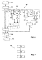
- FIG. 6 shows a circuit diagram of a further exemplary embodiment of a device for determining an estimate of the logarithm of an input variable
- FIG. 7 shows a flowchart of an exemplary embodiment of the present disclosure as a method.
- the idea of the Mitchell approximation consists in representing the number x as a product of two factors.
- the first factor is the nearest 2nd power which is less than or equal to x, which means that the second factor is a number in the right-open interval [1,2). It therefore holds that:
- k forms the integer component of the ld(x)
- f forms the non-integer fractional component of the ld(x).
- FIG. 1 shows a diagram of a comparison between the Mitchell approximation of the input variable x (denoted in the further discussion by m(x)) and the exact calculated value of the ld(x).
- the diagram from FIG. 1 represents on the abscissa the input variable x in the interval from 1 to 2, and on the ordinate the exactly calculated ld(x) and the value of the Mitchell approximation m(x).
- FIG. 1 reproduces the exact calculated value of the ld(x) on the dashed line, and the value of the Mitchell approximation of the input variable x is reproduced on the unbroken line.
- the approach presented further in different exemplary embodiments presents a possibility for providing a method and a circuit for quick and simple calculation of function values of the logarithmic function to the base 2 (Logarithmus Dualis) in a few steps or one step.
- the aim is to use the approach presented here to propose a method and a circuit for optimized calculation of a (desired) logarithm (an input variable).
- the advantage of the approach proposed here consists in the simple implementability in digital hardware, for example, and/or in the possibility of adapting the accuracy of the calculation to the requirements of the application, and when so doing calculating the result in a few steps or one step. It is true that other methods offer the possibility of adapting the accuracy to the requirements, but they calculate the Logarithmus Dualis not of a small number of steps, nor in one step. An example of this is the BKM algorithm.
- the ideal correction function c 1 ideal (x) is illustrated in a diagram in FIG. 2 .
- the input variable x is once again represented on the abscissa in the interval from 1 to 2.
- FIG. 2 in this case illustrates the ideal correction function c 1 ideal (x) (as unbroken line) and the two straight lines c 1 a (x) (as dashed and dotted line) and c 1 b (x) (as dashed line).
- said function is approximated by two straight lines by way of example (said procedure is denoted below as first-order approximation).
- the two straight lines pass respectively through one of the two zero points of the ideal correction function c 1 ideal (x) and intersect at a point on c 1 ideal (x).
- the y-coordinate of the point of intersection is the function value of c 1 ideal (x) at said point (that is to say c 1 ideal (1.5)).
- the straight line c 1 a (x) is therefore determined by the point (1.0) and the point (1.50, c 1 ideal (1.5)).
- the straight line c 1 b (x) is therefore determined by the point (1.50, c 1 ideal (1.5)) and the point (2.0).
- the absolute value of the gradients of the two straight lines is therefore identical.
- the first-order approximation for the ld(x) is therefore: ld ( x ) ⁇ m ( x )+ c 1 a ( x ) for x ⁇ [ 1.0,1.5) (9) ld ( x ) ⁇ m ( x )+ c 1 b ( x ) for x ⁇ [ 1.5,2.0)
- FIG. 3 shows a diagram which reproduces (with a designation of the axes corresponding to FIG. 1 or 2 ) a comparison between the exact calculation of the ld(x) (unbroken line) and the first-order approximation (dashed and dotted line).
- the first-order approximation is therefore substantially more accurate than the Mitchell approximation. It is, however, not exact.
- FIG. 4 shows a circuit diagram of an exemplary embodiment of a device 100 for determining an estimate s of the logarithm of an input variable x, said device 100 being understood as arrangement for calculating the first-order approximation. It is thereby possible to implement the formula (9) in hardware, for example.
- the device 100 comprises a register 110 which includes the value x (that is to say the input variable) of which the logarithm (ld) is to be determined.
- the Mitchell approximation for example, is determined for this value by means of the approximation unit 120 .
- the approximation unit 120 supplies as first variable the value k which corresponds to the integer component of the logarithm value of the input variable.
- the approximation unit 120 supplies as second variable the value f which (in accordance with the foregoing description) corresponds to an estimate of a non-integer component of the logarithmic value of the input variable.
- the first variable comprises the bits which represent the integer portion of the ld.
- the second variable comprises the bits which form the fractional portion of the ld(x).
- Circuits for implementing the approximation unit 120 which calculate the Mitchell approximation are known and can be implemented here, for example, using combinatorial logic.
- the device 100 comprises a determination unit 125 for determining the correcting quantity c 1 .
- said determination unit 125 receives the second variable f and determines the correcting quantity by using said second variable or individual components or symbols from the second variable.
- the determination unit 125 has an inverter 130 and a multiplexer 140 which are used to implement the terms (x ⁇ 1) and (2 ⁇ x) from equation (8) and the selection of the correct terms depending on the value of x.
- the multiplexer 140 is controlled by bit f ⁇ 1 (significance 2 ⁇ 1 ) of the data word f.
- the data word f is represented in formula (14) in two's complement in fixed point representation, the integer part is expanded with zeros.
- the point in formula (14) marks the radix point (corresponding to a decimal point).
- the term (1 ⁇ f) can be implemented approximately by the complement of the data word f.
- the inverter 130 therefore forms the complement of the data word f.
- either the data word f or the complement f of the constant k 1 is multiplied by a multiplier 150 .
- the inverter 130 , the multiplexer 140 , the multiplier 150 and the constant k 1 (which is, for example, extracted from an appropriate register 160 ) thus implement the selection of c 1 a (x) and/or c 1 b (x) and the calculation of the correcting quantity c 1 (see formula (16)).
- the multiplier 150 can advantageously be designed as a shift-and-add structure for the multiplication by the constant k 1 .
- An assessment unit 170 which can be designed as an adder, for example, assesses or forms the sum from the data word k, the data word f and the result of the multiplication c 1 and thereby assesses the first-order approximation for the Logarithmus Dualis of the input variable x.
- the result ld(x) which represents an estimate or approximate value s for the logarithm value of the input variable, is stored in a register 180 and output when required to a further processing unit which is not illustrated in FIG. 4 .
- the method can proceed analogously using a further correction function.
- FIG. 5 shows a diagram which (with a designation of the axes corresponding to FIG. 1 or 2 ) reproduces a profile of the ideal correction function c 2 ideal (x), which is yielded from the error of the first-order approximation and the exact logarithm value of the input variable.
- FIG. 5 represents an ideal correction function c 2 ideal (x) and four straight lines c 2 a (x), c 2 b (x), c 2 c (x) and c 2 d (x) which are described in more detail below.
- c 2 ideal (x) does not have one region with a curve profile opening downward and resembling a parabola, instead c 2 ideal (x) has two regions with a curve profile opening downward and resembling a parabola.
- the profile of the ideal correction function c 2 ideal (x) is approximated by two straight lines each in the region between two zero points. The two straight lines pass through one each of the zero points and intersect one another at a point on the ideal correction function c 2 ideal (x). The x-coordinate of the point of intersection is selected in the middle of the two zero points.
- the second-order approximation therefore runs: ld ( x ) ⁇ m ( x )+ c 1 a ( x )+ c 2 a ( x ) for x ⁇ [ 1.00,1.25) ld ( x ) ⁇ m ( x )+ c 1 a ( x )+ c 2 b ( x ) for x ⁇ [ 1.25,1.50) ld ( x ) ⁇ m ( x )+ c 1 b ( x )+ c 2 c ( x ) for x ⁇ [ 1.50,1.75) ld ( x ) ⁇ m ( x )+ c 1 b ( x )+ c 2 d ( x ) for x ⁇ [ 1.75,2.00) (18)
- Said method can be continued analogously for higher-order approximations.
- the correction functions for the first- (second-, third-, fourth-, . . . ) order approximations consist of one (two, 4, 8, . . . ) curves opening downward and resembling parabolas (corresponding to FIGS. 2 and 5 ). Said curves can respectively be approximated with twice the number of straight lines, that is to say the approximation takes place through two (4, 8, 16, . . . ) straight lines.
- FIG. 6 illustrates a circuit diagram of a device 100 for determining estimates of the logarithm of an input variable with an exemplary embodiment of an arrangement for calculating the second-order approximation.
- the correction term for the second-order approximation (which is also denoted as second correcting quantity) is added onto said first-order approximation.
- Said correction term is implemented by the blocks 190 to 240 , which form an extension unit of the determination unit 125 .
- the unit 250 forms an extension of the assessment unit 170 and can be assigned thereto logically.
- the inverter 190 and the multiplexer 200 implement the terms (x ⁇ 1.00), (1.50 ⁇ x), (x ⁇ 1.50) and (2.00 ⁇ x) from formula (17) by analogy with the procedure for the first-order approximation.
- the selection of the correct constants for the multiplication (k 2 or k 3 ) is undertaken by the multiplexer 240 with the aid of the data bit f ⁇ 1 .
- the multiplier 210 multiplies the constant by the variable term and forms as a result the correction term c 2 , which is added on for the first-order approximation by the adder 250 , in order to obtain the estimate or approximation value s of the logarithm of the input variable x.
- the combination of the first variable k, the second variable f as well as the first correcting quantity c 1 and the second correcting quantity c 2 can also take place in a single step or in a single unit, as the person skilled in the art will easily recognize from the circuitry and/or the description and with knowledge of the mathematical and algebraic laws.
- the result is stored in register 180 as an estimate or approximation value s of the logarithm of the input variable.
- FIG. 7 shows a flowchart of an exemplary embodiment of the present disclosure as a method 700 for determining an estimate of the logarithm of an input variable.
- the method 700 comprises a step 710 of approximating a first variable from the input variable, the first variable corresponding to the integer component of the logarithmic value of the input variable, there being approximated a second variable which corresponds to an estimate of a non-integer component of the logarithmic value of the input variable.
- the method 700 comprises a step 720 of determining a correcting quantity by means of the second variable, and a step 730 of assessing the estimate s of the logarithm of the input variable by combining the first variable with the second variable and the correcting quantity.
- the approach presented here can, for example, serve to implement the calculation of power functions (for example roots, powers x 2 , x 3 , . . . ) in ASICs in fixed point arithmetic cost effectively via logarithms.
- power functions for example roots, powers x 2 , x 3 , . . .
- logarithms can be used to check multipliers, dividers and root calculators for correct function during operation, which increases the safety in safety-critical applications (ISO 26262).
- an exemplary embodiment comprises an “and/or” combination between a first feature and a second feature, this is to be read in the sense that the exemplary embodiment according to an embodiment has both the first feature and the second feature, and in accordance with a further embodiment has either only the first feature or only the second feature.
Abstract
Description
-
- an approximation unit which is designed to determine from the input variable a first variable which corresponds to the integer component of the logarithmic value of the input variable, the approximation unit further being designed to determine a second variable which corresponds to an estimate of a non-integer component of the logarithmic value of the input variable;
- a determination unit for determining a correcting quantity by using the second variable; and
- an assessment unit for assessing the estimate of the logarithm of the input variable by combining the first variable with the second variable and the correcting quantity.
-
- a read in interface for reading in a signal which represents a physical variable;
- a device according to a variant presented here which is designed to process the physical variable or a value derived from the physical variable as input variable; and
- a control and/or signaling unit which is designed to use the estimate to provide a control signal and/or a data signal.
-
- approximation of a first variable from the input variable, the first variable corresponding to the integer component of the logarithmic value of the input variable, there being approximated a second variable, which corresponds to an estimate of a non-integer component of the logarithmic value of the input variable;
- using the second variable to determine a correcting quantity; and
- assessing the estimate of the logarithm of the input variable by combining the first variable with the second variable and the correcting quantity.
D:={xε
ld(x)=ld(2k−(1+f))=ld(2k)+ld(1+f)=k+ld(1+f) (3)
ld(x norm)=ld(1+f)≈f (4)
ld(x)≈k+f (5)
ld(x)=m(x)+c1ideal(x) (7)
c1a(x)=2·c1ideal(1.5)·(x−1)=k1·(x−1) for x ε[1.0,1.5) (8)
c1b(x)=2·c1ideal(1.5)·(2−x)=k1·(2−x) for x ε[1.5,2.0)
ld(x)≈m(x)+c1a(x) for x ε[1.0,1.5) (9)
ld(x)≈m(x)+c1b(x) for x ε[1.5,2.0)
k=[k m-1 . . . k 1 k 0 ]=k m-1·2m-1 + . . . +k 1·21 +k 0·20 (10)
f=[k −1 . . . f −(n-1) f −n ]=f −1·2−1 + . . . +f −(n-1)·2−(n-1) +f −n·2−n
use f −1=0→c1a(x) (11)
use f −1=1→c1b(x)
(x−1)=f (12)
(2−x)=(2−(1+f))=(1−f) (13)
f=[0 . . . 0 0·f −1 . . . f −(n-1) f −n] (14)
=0·(−2)m-1+0·2m-2+ . . . +0·20 +f −1·2−1 + . . . +f −(n−1)·2−(n−1) +f −n·2−n
f −1=0→Calculation of cl a(x)=k1·f (16)
f −1=1→Calculation of cl b(x)=k1·
c2a(x)=4·c2ideal(1.25)·(x−1.00)=k2·(x−1.00) for xε[1.00,1.25)
c2b(x)=4·c2ideal(1.25)·(1.50−x)=k2·(1.50−x) for xε[1.25,1.50)
c2c(x)=4·c2ideal(1.75)·(x−1.50)=k3·(x−1.50) for xε[1.50,1.75)
c2d(x)=4·c2ideal(1.75)·(2.00−x)=k3·(2.00−x) for xε[1.75,2.00) (17)
ld(x)≈m(x)+c1a(x)+c2a(x) for xε[1.00,1.25)
ld(x)≈m(x)+c1a(x)+c2b(x) for xε[1.25,1.50)
ld(x)≈m(x)+c1b(x)+c2c(x) for xε[1.50,1.75)
ld(x)≈m(x)+c1b(x)+c2d(x) for xε[1.75,2.00) (18)
Claims (8)
Applications Claiming Priority (3)
| Application Number | Priority Date | Filing Date | Title |
|---|---|---|---|
| DE102014200465.9 | 2014-01-14 | ||
| DE102014200465 | 2014-01-14 | ||
| DE102014200465.9A DE102014200465A1 (en) | 2014-01-14 | 2014-01-14 | Apparatus and method for determining an estimate of the logarithm of an input |
Publications (2)
| Publication Number | Publication Date |
|---|---|
| US20150199303A1 US20150199303A1 (en) | 2015-07-16 |
| US9594728B2 true US9594728B2 (en) | 2017-03-14 |
Family
ID=53484914
Family Applications (1)
| Application Number | Title | Priority Date | Filing Date |
|---|---|---|---|
| US14/596,251 Expired - Fee Related US9594728B2 (en) | 2014-01-14 | 2015-01-14 | Device and method for determining an estimate of the logarithm of an input variable |
Country Status (2)
| Country | Link |
|---|---|
| US (1) | US9594728B2 (en) |
| DE (1) | DE102014200465A1 (en) |
Cited By (1)
| Publication number | Priority date | Publication date | Assignee | Title |
|---|---|---|---|---|
| CN107479856A (en) * | 2017-08-09 | 2017-12-15 | 珠海市杰理科技股份有限公司 | Arctan function data structure and method for building up, function value-acquiring method and device |
Citations (7)
| Publication number | Priority date | Publication date | Assignee | Title |
|---|---|---|---|---|
| US5604691A (en) * | 1995-01-31 | 1997-02-18 | Motorola, Inc. | Logarithm/inverse-logarithm converter utilizing a truncated Taylor series and method of use thereof |
| US5642305A (en) * | 1995-01-31 | 1997-06-24 | Motorola, Inc. | Logarithm/inverse-logarithm converter and method of using same |
| US5801974A (en) * | 1995-10-13 | 1998-09-01 | Samsung Electronics Co., Ltd. | Calculation method and circuit for obtaining a logarithmic approximation value |
| US20030014453A1 (en) * | 2001-07-16 | 2003-01-16 | Raghu Challa | Logarithmic lookup tables |
| US6711601B2 (en) * | 2000-04-14 | 2004-03-23 | Renesas Technology Corp. | Logarithmic arithmetic unit avoiding division as far as predetermined arithmetic precision is guaranteed |
| US7509363B2 (en) * | 2001-07-30 | 2009-03-24 | Ati Technologies Ulc | Method and system for approximating sine and cosine functions |
| US7539717B2 (en) * | 2005-09-09 | 2009-05-26 | Via Technologies, Inc. | Logarithm processing systems and methods |
-
2014
- 2014-01-14 DE DE102014200465.9A patent/DE102014200465A1/en not_active Withdrawn
-
2015
- 2015-01-14 US US14/596,251 patent/US9594728B2/en not_active Expired - Fee Related
Patent Citations (7)
| Publication number | Priority date | Publication date | Assignee | Title |
|---|---|---|---|---|
| US5604691A (en) * | 1995-01-31 | 1997-02-18 | Motorola, Inc. | Logarithm/inverse-logarithm converter utilizing a truncated Taylor series and method of use thereof |
| US5642305A (en) * | 1995-01-31 | 1997-06-24 | Motorola, Inc. | Logarithm/inverse-logarithm converter and method of using same |
| US5801974A (en) * | 1995-10-13 | 1998-09-01 | Samsung Electronics Co., Ltd. | Calculation method and circuit for obtaining a logarithmic approximation value |
| US6711601B2 (en) * | 2000-04-14 | 2004-03-23 | Renesas Technology Corp. | Logarithmic arithmetic unit avoiding division as far as predetermined arithmetic precision is guaranteed |
| US20030014453A1 (en) * | 2001-07-16 | 2003-01-16 | Raghu Challa | Logarithmic lookup tables |
| US7509363B2 (en) * | 2001-07-30 | 2009-03-24 | Ati Technologies Ulc | Method and system for approximating sine and cosine functions |
| US7539717B2 (en) * | 2005-09-09 | 2009-05-26 | Via Technologies, Inc. | Logarithm processing systems and methods |
Non-Patent Citations (1)
| Title |
|---|
| Mitchell, J. N., "Computer Multiplication and Division Using Binary Logarithms", IRE Transactions on Electronic Computers, 1962, EC-11, pp. 512-517. |
Cited By (1)
| Publication number | Priority date | Publication date | Assignee | Title |
|---|---|---|---|---|
| CN107479856A (en) * | 2017-08-09 | 2017-12-15 | 珠海市杰理科技股份有限公司 | Arctan function data structure and method for building up, function value-acquiring method and device |
Also Published As
| Publication number | Publication date |
|---|---|
| DE102014200465A1 (en) | 2015-07-16 |
| US20150199303A1 (en) | 2015-07-16 |
Similar Documents
| Publication | Publication Date | Title |
|---|---|---|
| US5726924A (en) | Exponentiation circuit utilizing shift means and method of using same | |
| US20120259904A1 (en) | Floating point format converter | |
| KR102358013B1 (en) | Close path fast incremented sum in a three-path fused multiply-add design | |
| US6976043B2 (en) | Technique for approximating functions based on lagrange polynomials | |
| US20080109501A1 (en) | Modular multiplication method with precomputation using one known operand | |
| CN107305484B (en) | Nonlinear function operation device and method | |
| EP3447634B1 (en) | Non-linear function computing device and method | |
| US11163533B2 (en) | Floating point unit for exponential function implementation | |
| JPH0319569B2 (en) | ||
| US8914431B2 (en) | Range check based lookup tables | |
| US10684825B2 (en) | Compressing like magnitude partial products in multiply accumulation | |
| CN107038014B (en) | Rounding an inverse square root result | |
| US20170017467A1 (en) | Integer/floating point divider and square root logic unit and associates methods | |
| US20090172069A1 (en) | Method and apparatus for integer division | |
| US6182100B1 (en) | Method and system for performing a logarithmic estimation within a data processing system | |
| US8504954B1 (en) | Methodology for automatically generating series-approximated components | |
| US9594728B2 (en) | Device and method for determining an estimate of the logarithm of an input variable | |
| Malik | High throughput floating-point dividers implemented in FPGA | |
| TWI754680B (en) | Apparatus and method of generating starting estimate, manufacturing method and testing method | |
| US9612796B2 (en) | Method and device for checking a digital multiplier | |
| US9563400B2 (en) | Optimized structure for hexadecimal and binary multiplier array | |
| US20190171419A1 (en) | Arithmetic processing device and control method of arithmetic processing device | |
| US10949498B1 (en) | Softmax circuit | |
| US8713084B2 (en) | Method, system and computer program product for verifying floating point divide operation results | |
| US9612800B2 (en) | Implementing a square root operation in a computer system |
Legal Events
| Date | Code | Title | Description |
|---|---|---|---|
| AS | Assignment |
Owner name: ROBERT BOSCH GMBH, GERMANY Free format text: ASSIGNMENT OF ASSIGNORS INTEREST;ASSIGNOR:UHL, ALEXANDER;REEL/FRAME:035122/0244 Effective date: 20150220 |
|
| STCF | Information on status: patent grant |
Free format text: PATENTED CASE |
|
| FEPP | Fee payment procedure |
Free format text: MAINTENANCE FEE REMINDER MAILED (ORIGINAL EVENT CODE: REM.); ENTITY STATUS OF PATENT OWNER: LARGE ENTITY |
|
| LAPS | Lapse for failure to pay maintenance fees |
Free format text: PATENT EXPIRED FOR FAILURE TO PAY MAINTENANCE FEES (ORIGINAL EVENT CODE: EXP.); ENTITY STATUS OF PATENT OWNER: LARGE ENTITY |
|
| STCH | Information on status: patent discontinuation |
Free format text: PATENT EXPIRED DUE TO NONPAYMENT OF MAINTENANCE FEES UNDER 37 CFR 1.362 |
|
| FP | Lapsed due to failure to pay maintenance fee |
Effective date: 20210314 |