US9566188B2 - Automatically switching different aspiration levels and/or pumps to an ocular probe - Google Patents
Automatically switching different aspiration levels and/or pumps to an ocular probe Download PDFInfo
- Publication number
- US9566188B2 US9566188B2 US12/614,093 US61409309A US9566188B2 US 9566188 B2 US9566188 B2 US 9566188B2 US 61409309 A US61409309 A US 61409309A US 9566188 B2 US9566188 B2 US 9566188B2
- Authority
- US
- United States
- Prior art keywords
- pump
- flow
- aspiration
- probe
- fluid
- Prior art date
- Legal status (The legal status is an assumption and is not a legal conclusion. Google has not performed a legal analysis and makes no representation as to the accuracy of the status listed.)
- Active, expires
Links
Images


Classifications
-
- A—HUMAN NECESSITIES
- A61—MEDICAL OR VETERINARY SCIENCE; HYGIENE
- A61F—FILTERS IMPLANTABLE INTO BLOOD VESSELS; PROSTHESES; DEVICES PROVIDING PATENCY TO, OR PREVENTING COLLAPSING OF, TUBULAR STRUCTURES OF THE BODY, e.g. STENTS; ORTHOPAEDIC, NURSING OR CONTRACEPTIVE DEVICES; FOMENTATION; TREATMENT OR PROTECTION OF EYES OR EARS; BANDAGES, DRESSINGS OR ABSORBENT PADS; FIRST-AID KITS
- A61F9/00—Methods or devices for treatment of the eyes; Devices for putting-in contact lenses; Devices to correct squinting; Apparatus to guide the blind; Protective devices for the eyes, carried on the body or in the hand
- A61F9/007—Methods or devices for eye surgery
- A61F9/00736—Instruments for removal of intra-ocular material or intra-ocular injection, e.g. cataract instruments
- A61F9/00745—Instruments for removal of intra-ocular material or intra-ocular injection, e.g. cataract instruments using mechanical vibrations, e.g. ultrasonic
-
- A—HUMAN NECESSITIES
- A61—MEDICAL OR VETERINARY SCIENCE; HYGIENE
- A61F—FILTERS IMPLANTABLE INTO BLOOD VESSELS; PROSTHESES; DEVICES PROVIDING PATENCY TO, OR PREVENTING COLLAPSING OF, TUBULAR STRUCTURES OF THE BODY, e.g. STENTS; ORTHOPAEDIC, NURSING OR CONTRACEPTIVE DEVICES; FOMENTATION; TREATMENT OR PROTECTION OF EYES OR EARS; BANDAGES, DRESSINGS OR ABSORBENT PADS; FIRST-AID KITS
- A61F9/00—Methods or devices for treatment of the eyes; Devices for putting-in contact lenses; Devices to correct squinting; Apparatus to guide the blind; Protective devices for the eyes, carried on the body or in the hand
- A61F9/007—Methods or devices for eye surgery
- A61F9/00736—Instruments for removal of intra-ocular material or intra-ocular injection, e.g. cataract instruments
- A61F9/00754—Instruments for removal of intra-ocular material or intra-ocular injection, e.g. cataract instruments for cutting or perforating the anterior lens capsule, e.g. capsulotomes
-
- A61M1/0031—
-
- A61M1/0037—
-
- A61M1/0039—
-
- A61M1/0058—
-
- A61M1/0062—
-
- A61M1/0064—
-
- A—HUMAN NECESSITIES
- A61—MEDICAL OR VETERINARY SCIENCE; HYGIENE
- A61M—DEVICES FOR INTRODUCING MEDIA INTO, OR ONTO, THE BODY; DEVICES FOR TRANSDUCING BODY MEDIA OR FOR TAKING MEDIA FROM THE BODY; DEVICES FOR PRODUCING OR ENDING SLEEP OR STUPOR
- A61M1/00—Suction or pumping devices for medical purposes; Devices for carrying-off, for treatment of, or for carrying-over, body-liquids; Drainage systems
- A61M1/71—Suction drainage systems
- A61M1/74—Suction control
- A61M1/75—Intermittent or pulsating suction
-
- A—HUMAN NECESSITIES
- A61—MEDICAL OR VETERINARY SCIENCE; HYGIENE
- A61M—DEVICES FOR INTRODUCING MEDIA INTO, OR ONTO, THE BODY; DEVICES FOR TRANSDUCING BODY MEDIA OR FOR TAKING MEDIA FROM THE BODY; DEVICES FOR PRODUCING OR ENDING SLEEP OR STUPOR
- A61M1/00—Suction or pumping devices for medical purposes; Devices for carrying-off, for treatment of, or for carrying-over, body-liquids; Drainage systems
- A61M1/71—Suction drainage systems
- A61M1/76—Handpieces
-
- A—HUMAN NECESSITIES
- A61—MEDICAL OR VETERINARY SCIENCE; HYGIENE
- A61M—DEVICES FOR INTRODUCING MEDIA INTO, OR ONTO, THE BODY; DEVICES FOR TRANSDUCING BODY MEDIA OR FOR TAKING MEDIA FROM THE BODY; DEVICES FOR PRODUCING OR ENDING SLEEP OR STUPOR
- A61M1/00—Suction or pumping devices for medical purposes; Devices for carrying-off, for treatment of, or for carrying-over, body-liquids; Drainage systems
- A61M1/71—Suction drainage systems
- A61M1/77—Suction-irrigation systems
- A61M1/772—Suction-irrigation systems operating alternately
-
- A—HUMAN NECESSITIES
- A61—MEDICAL OR VETERINARY SCIENCE; HYGIENE
- A61M—DEVICES FOR INTRODUCING MEDIA INTO, OR ONTO, THE BODY; DEVICES FOR TRANSDUCING BODY MEDIA OR FOR TAKING MEDIA FROM THE BODY; DEVICES FOR PRODUCING OR ENDING SLEEP OR STUPOR
- A61M1/00—Suction or pumping devices for medical purposes; Devices for carrying-off, for treatment of, or for carrying-over, body-liquids; Drainage systems
- A61M1/80—Suction pumps
- A61M1/804—Suction pumps using Laval or Venturi jet pumps
-
- A—HUMAN NECESSITIES
- A61—MEDICAL OR VETERINARY SCIENCE; HYGIENE
- A61M—DEVICES FOR INTRODUCING MEDIA INTO, OR ONTO, THE BODY; DEVICES FOR TRANSDUCING BODY MEDIA OR FOR TAKING MEDIA FROM THE BODY; DEVICES FOR PRODUCING OR ENDING SLEEP OR STUPOR
- A61M1/00—Suction or pumping devices for medical purposes; Devices for carrying-off, for treatment of, or for carrying-over, body-liquids; Drainage systems
- A61M1/71—Suction drainage systems
- A61M1/72—Cassettes forming partially or totally the fluid circuit
-
- A—HUMAN NECESSITIES
- A61—MEDICAL OR VETERINARY SCIENCE; HYGIENE
- A61M—DEVICES FOR INTRODUCING MEDIA INTO, OR ONTO, THE BODY; DEVICES FOR TRANSDUCING BODY MEDIA OR FOR TAKING MEDIA FROM THE BODY; DEVICES FOR PRODUCING OR ENDING SLEEP OR STUPOR
- A61M2205/00—General characteristics of the apparatus
- A61M2205/33—Controlling, regulating or measuring
- A61M2205/3331—Pressure; Flow
-
- A—HUMAN NECESSITIES
- A61—MEDICAL OR VETERINARY SCIENCE; HYGIENE
- A61M—DEVICES FOR INTRODUCING MEDIA INTO, OR ONTO, THE BODY; DEVICES FOR TRANSDUCING BODY MEDIA OR FOR TAKING MEDIA FROM THE BODY; DEVICES FOR PRODUCING OR ENDING SLEEP OR STUPOR
- A61M2205/00—General characteristics of the apparatus
- A61M2205/50—General characteristics of the apparatus with microprocessors or computers
-
- A—HUMAN NECESSITIES
- A61—MEDICAL OR VETERINARY SCIENCE; HYGIENE
- A61M—DEVICES FOR INTRODUCING MEDIA INTO, OR ONTO, THE BODY; DEVICES FOR TRANSDUCING BODY MEDIA OR FOR TAKING MEDIA FROM THE BODY; DEVICES FOR PRODUCING OR ENDING SLEEP OR STUPOR
- A61M2210/00—Anatomical parts of the body
- A61M2210/06—Head
- A61M2210/0612—Eyes
-
- A—HUMAN NECESSITIES
- A61—MEDICAL OR VETERINARY SCIENCE; HYGIENE
- A61M—DEVICES FOR INTRODUCING MEDIA INTO, OR ONTO, THE BODY; DEVICES FOR TRANSDUCING BODY MEDIA OR FOR TAKING MEDIA FROM THE BODY; DEVICES FOR PRODUCING OR ENDING SLEEP OR STUPOR
- A61M2210/00—Anatomical parts of the body
- A61M2210/06—Head
- A61M2210/0618—Nose
Definitions
- the present invention relates generally to the field of surgery, and more specifically to devices, systems, and methods for treatment of an eye.
- Exemplary embodiments allow enhanced treatment to structures within an eye by at least once (though more commonly repeatedly or even cyclically) applying different levels and/or types of aspiration to an ocular probe, often such that the aspiration changes during a treatment of a particular eye.
- the material may be removed from an anterior or posterior chamber of the eye, such as for phacoemulsification of cataracts, treatment of retinal diseases, vitrectomy, and the like.
- the optical elements of the eye include both a cornea (at the front of the eye) and a lens within the eye.
- the lens and cornea work together to focus light onto the retina at the back of the eye.
- the lens also changes in shape, adjusting the focus of the eye to vary between viewing near objects and far objects.
- the lens is found just behind the pupil, and within a capsular bag. This capsular bag is a thin, relatively delicate structure which separates the eye into anterior and posterior chambers.
- Cataracts may form in the hard central nucleus of the lens, in the softer peripheral cortical portion of the lens, or at the back of the lens near the capsular bag.
- Cataracts can be treated by the replacement of the cloudy lens with an artificial lens.
- Phacoemulsification systems often use ultrasound energy to fragment the lens and aspirate the lens material from within the capsular bag. This may allow the remaining capsular bag to be used for positioning of the artificial lens, and maintains the separation between the anterior portion of the eye and the vitreous humour in the posterior chamber of the eye.
- a corresponding irrigation flow may be introduced into the eye so that the total volume of fluid in the eye does not change excessively. If the total volume of fluid in the eye is allowed to get too low at any time during the procedure, the eye may collapse and cause significant tissue damage. Similarly, excessive pressure within the eye may strain and injure tissues of the eye.
- aspiration flow systems can generally be classified in two categories: 1) volumetric-based aspiration flow systems using positive displacement pumps; and 2) vacuum-based aspiration systems using a vacuum source, typically applied to the aspiration flow through an air-liquid interface.
- positive displacement aspiration systems peristaltic pumps (which use rotating rollers that press against a flexible tubing to induce flow) are commonly employed. Such pumps provide accurate control over the flow volume. The pressure of the flow, however, is less accurately controlled and the variations in vacuum may result in the feel or traction of the handpiece varying during a procedure. Peristaltic and other displacement pump systems may also be somewhat slow for some procedures.
- Vacuum rise times tend to be slower for peristaltic systems than venturi systems. This may result in an overall sluggish feel to the surgeon.
- the ultrasonic vibrations of a phacoemulsification tip may (despite peristaltic aspiration flow into the tip) inhibit the desired fragmentation-inducing engagement between the tip and tissue particles.
- Vacuum-based aspiration systems provide accurate control over the fluid pressure within the eye, particularly when combined with gravity-fed irrigation systems. While vacuum-based systems can (in some circumstances) result in excessive fluid flows, they may have advantages when, for example, it is desired to bring tissue fragments to the probe, or when removing a relatively large quantity of the viscous vitreous humour from the posterior chamber of the eye.
- venturi pump and other vacuum-based aspiration flow systems are subject to pressure surges during occlusion of the treatment probe, and such pressure surges may decrease the surgeon's control over the eye treatment procedure.
- Displacement pump systems are similarly subject to vacuum spikes during and immediately following occlusion of the probe.
- One embodiment of the invention may include a method for applying aspiration to a probe.
- the method may be computer implemented.
- the method may include applying a base vacuum level from a first pump to a probe to achieve a base level flow-rate, applying a secondary vacuum level from a second pump to the probe to achieve an additive level flow-rate, which is additional to the base level flow-rate, and detecting that the probe is at least partially occluded by detecting an increased secondary vacuum level.
- Another embodiment of the invention may include a method for removing material from an eye.
- the method may include generating a base level aspiration flow by applying a base aspiration pressure differential using a pressure pump to an aspiration flow pathway from the eye, generating an additive level flow, during the base level flow, by pumping the additive level flow with a volumetric pump, and detecting occlusion of the aspiration flow pathway by detecting an increased pressure differential above the base pressure differential generated by the volumetric pump.
- Yet another embodiment of the invention may include a system for removing material from within an eye.
- the system may include a probe having a distal tip insertable into the eye, wherein the tip comprises an aspiration port, and a console coupled with/to the port along an aspiration pathway, wherein the console comprises a processor and a pump system for providing a base level aspiration flow by applying a base aspiration pressure differential and an additive level flow, during the base level flow, wherein the processor is configured to detect occlusion of the aspiration flow pathway by detecting an increased pressure differential above the base pressure.
- the pump system may comprise multiple pumps, including a first pump and a second pump, wherein the first pump and the second pump may be a vacuum based (pressure) pump and/or a flow based (volumetric) pump.
- Yet another embodiment of the invention may include a method for applying aspiration and irrigation to a phacoemulsification device.
- the method may be computer implemented.
- the method may include applying a low flow-rate aspiration from a first pump to an aspiration port of a probe, applying a low flow-rate irrigation from a fluid source to an irrigation port of the probe while applying the low flow-rate aspiration, transitioning from the low flow rate aspiration to a high flow-rate aspiration from a second pump to the aspiration port, and transitioning from the low flow-rate irrigation to a high flow-rate irrigation while transitioning from the low flow-rate aspiration to the high flow-rate aspiration.
- Yet another embodiment of the invention may include a system for removing material from within an eye.
- the system may include a probe having a distal tip insertable into the eye, wherein the tip comprises an aspiration port and an irrigation port, and a console coupled with/to the port along an aspiration pathway, wherein the console comprises a processor and a pump system for providing a first pump rate and a second pump rate higher than the first pump rate, and a irrigation system for providing a variable irrigation rate, the processor configured to automatically switch from the first pump rate to the second pump rate and vary the irrigation rate according to the pump rates.
- the pump system may comprise multiple pumps, including a first pump and second pump.
- Yet another embodiment of the invention may include a method for applying aspiration to a probe.
- the method may be computer implemented.
- the method may include applying a aspiration flow-rate first pump to a probe to achieve a first level flow-rate, tracking a vacuum level to control aspiration of probe, setting a threshold vacuum level, switching from the first level flow-rate to a second level flow-rate from a second pump, and tracking flow rate to control the aspiration of the probe when the threshold vacuum level is passed.
- the method may include switching from the first pump to a second pump, while maintaining the same flow-rate.
- Yet another embodiment of the invention may include a system for removing material from within an eye.
- the system may include a probe having a distal tip insertable into the eye, wherein the tip comprises an aspiration port, and a console coupled with/to the port along an aspiration pathway, wherein the console comprises a processor and a pump system for providing a first pump rate and a second pump rate higher than the first pump rate.
- the processor is configured to automatically switch from the first pump rate to the second pump rate and control aspiration of the probe by tracking a vacuum level up to a threshold, and control aspiration of the probe by tracking a flow rate of the probe when the threshold has been passed.
- the pump system may comprise multiple pumps, including a first pump and a second pump.
- Yet another embodiment of the invention may a include a phacoemulsification system, comprising a handpiece, wherein the handpiece comprises a needle having at least one port and wherein the needle is configured to move in a substantially longitudinal and a non-longitudinal direction; a first pump, wherein the first pump is configured to operate when a longitudinal cutting mode is selected; and a second pump, wherein the second pump is configured to operate when a non-longitudinal cutting mode is selected.
- the first pump may comprise a flow based pump and the second pump may comprise a vacuum based pump.
- the first pump may comprise a vacuum based pump and the second pump may comprise a vacuum based pump.
- non-longitudinal direction may be selected from the group consisting of transversal and torsional.
- the invention may further comprise a foot pedal, wherein the foot pedal is configured to move in a first direction and a second direction, wherein the first direction is configured to control the first pump and the second direction is configured to control the second pump.
- the first direction and the second direction may be selected from the group consisting of yaw and pitch.
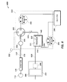
- FIG. 1 illustrates an exemplary phacoemulsification/vitrectomy irrigation/aspiration system in a functional block diagram to show the components and interfaces for a safety critical medical instrument system that may be employed in accordance with an embodiment of the present invention.
- FIGS. 2A and 2B are a functional block diagrams of an exemplary surgical cassette venting systems, according to embodiments of the invention.
- FIG. 4 is a functional block diagram illustrating a surgical cassette venting system configured for peristaltic aspiration operation, according to one embodiment of the invention.
- FIG. 5 is a functional block diagram illustrating a surgical cassette venting system configured for peristaltic venting operation, according to one embodiment of the invention.
- FIG. 6 is a functional block diagram illustrating a surgical cassette venting system configured for vacuum regulator aspiration operation, according to one embodiment of the invention.
- FIG. 7 is a functional block diagram illustrating a surgical cassette venting system configured for vacuum regulator venting operation, according to one embodiment of the invention.
- FIG. 8 is a graphical depiction of the operation of a surgical system, according to one embodiment of the invention.
- FIG. 9A is a flow chart of a method for applying aspiration to a probe, according to one embodiment of the invention.
- FIG. 9B is a graphical depiction of the operation of a surgical system, according to one embodiment of the invention.
- FIG. 10A is a flow chart of a method for applying aspiration and irrigation to a probe, according to one embodiment of the invention.
- FIG. 10B is a graphical depiction of the operation of a surgical system, according to one embodiment of the invention.
- FIG. 11B is a graphical depiction of the operation of a surgical system, according to one embodiment of the invention.
- FIG. 1 illustrates an exemplary phacoemulsification/vitrectomy system 100 in a functional block diagram to show the components and interfaces for a safety critical medical instrument system that may be employed in accordance with an aspect of the present invention.
- a serial communication cable 103 connects GUI host 101 module and instrument host 102 module for the purposes of controlling the surgical instrument host 102 by the GUI host 101 .
- GUI host 101 and instrument host 102 may be connected wirelessly.
- Instrument host 102 may be considered a computational device in the arrangement shown, but other arrangements are possible.
- An interface communications cable 120 is connected to instrument host 102 module for distributing instrument sensor data 121 , and may include distribution of instrument settings and parameters information, to other systems, subsystems and modules within and external to instrument host 102 module. Although shown connected to the instrument host 102 module, interface communications cable 120 may be connected or realized on any other subsystem (not shown) that could accommodate such an interface device able to distribute the respective data.
- a switch module associated with foot pedal 104 may transmit control signals relating internal physical and virtual switch position information as input to the instrument host 102 over serial communications cable 105 (although foot pedal 104 may be connected wireless, e.g. Bluetooth, IR).
- Instrument host 102 may provide a database file system for storing configuration parameter values, programs, and other data saved in a storage device (not shown).
- the database file system may be realized on the GUI host 101 or any other subsystem (not shown) that could accommodate such a file system.
- the foot pedal system ( 104 ) can be configured as dual linear. In this configuration, the surgeon can dictate the system to operate with the peristaltic pump in the traditional pitch and add the venturi vacuum with the yaw mechanism.
- the foot pedal 104 can also combine longitudinal cutting modes with a certain pump and non-longitudinal cutting modes (i.e., transversal, torsion, etc.) with a different pump for example, the foot pedal pitch could control a peristaltic pump with longitudinal ultrasonic cutting, and the yaw could control the venturi pump with non-longitudinal cutting.
- the foot pedal can also be configured to operate using a certain pump by yawing to the left and operate a second pump by yawing to the right. This gives the user the ability to switch-on-the-fly without accessing the user interface which may be timely and cumbersome. Control of one or more pumps may be programmed to the pitch and/or yaw directional movement of a treadle of foot pedal 104 and/or to any switch located on foot pedal 104
- the phacoemulsification/vitrectomy system 100 has a handpiece 110 that includes a needle and electrical means, typically a piezoelectric crystal, for ultrasonically vibrating the needle.
- the instrument host 102 supplies power on line 111 to a phacoemulsification/vitrectomy handpiece 110 .
- An irrigation fluid source 112 can be fluidly coupled with/to handpiece 110 through line 113 .
- the irrigation fluid and ultrasonic power are applied by handpiece 110 to an eye, or affected area or region, indicated diagrammatically by block 114 .
- the irrigation source may be routed to eye 114 through a separate pathway independent of the handpiece.
- Aspiration is provided to eye 114 by one or more pumps (not shown), such as a peristaltic pump, via the instrument host 102 , through lines 115 and 116 .
- pumps such as a peristaltic pump
- a surgeon/operator may select an amplitude of electrical pulses either using the handpiece, foot pedal, via the instrument host and/or GUI host, and/or by voice command.
- the instrument host 102 generally comprises at least one processor board.
- Instrument host 102 may include many of the components of a personal computer, such as a data bus, a memory, input and/or output devices (including a touch screen (not shown)), and the like.
- Instrument host 102 will often include both hardware and software, with the software typically comprising machine readable code or programming instructions for implementing one, some, or all of the methods described herein.
- the code may be embodied by a tangible media such as a memory, a magnetic recording media, an optical recording media, or the like.
- a controller may have (or be coupled with/to) a recording media reader, or the code may be transmitted to instrument host 102 by a network connection such as an internet, an intranet, an Ethernet, a wireless network, or the like.
- instrument host 102 may include stored data for implementing the methods described herein, and may generate and/or store data that records parameters reflecting the treatment of one or more patients.
- the present system enables aspiration, venting, or reflux functionality in or with the phacoemulsification system and may comprise components including, but not limited to, a flow selector valve, two or more pumps, a reservoir, and a collector, such as a collection bag or a device having similar functionality.
- the collector in the present design collects aspirant from the ocular surgical procedure.
- FIG. 2A illustrates an exemplary surgical cassette system in a functional block diagram that shows the components and interfaces that may be employed in accordance with an aspect of the present design.
- An irrigation source 46 of, and/or controlled by, instrument host 102 optionally provides irrigation fluid pressure control via an irrigation line 51 by relying at least in part on a gravity pressure head that varies with a height of an irrigation fluid bag or the like.
- An irrigation on/off pinch valve 48 may generally include a short segment of a flexible conduit of cassette 16 A, which can be engaged and actuated by an actuator of the instrument host 102 , with a surface of the cassette body often being disposed opposite the actuator to facilitate closure of the conduit lumen.
- Alternative irrigation flow systems may include positive displacement pumps, alternative fluid pressurization drive systems, fluid pressure or flow modulating valves, and/or the like.
- irrigation fluid is alternatively or additionally provided to a separate handpiece (not shown).
- the aspiration flow network 50 generally provides an aspiration flow path 52 that can couple an aspiration port in the tip of handpiece 110 to either a peristaltic pump 54 , formed by engagement of cassette 16 A with instrument host 102 , and/or a holding tank 56 . Fluid aspirated through the handpiece 110 may be contained in holding tank 56 regardless of whether the aspiration flow is induced by peristaltic pump 54 or the vacuum applied to the holding tank 56 via pump 57 . When pinch valve 58 is closed and peristaltic pump 54 is in operation, pumping of the aspiration flow may generally be directed by the peristaltic pump 54 , independent of the pressure in the holding tank 56 .
- peristaltic pump 54 when peristaltic pump 54 is off, flow through the peristaltic pump may be halted by pinching of the elastomeric tubing arc of the peristaltic pump by one or more of the individual rollers of the peristaltic pump rotor.
- any aspiration fluid drawn into the aspiration network when peristaltic pump 54 is off will typically be effected by opening of a pinch valve 58 so that the aspiration port of the probe is in fluid communication with the holding tank.
- the pressure within tank 56 may be maintained at a controlled vacuum level, often at a fixed vacuum level, by a vacuum system 59 of instrument host 102 .
- Vacuum system 59 may comprise a Venturi pump 57 , a rotary vane pump, a vacuum source, a vent valve 44 , a filter and/or the like.
- Aspiration flow fluid that drains into holding tank 56 may be removed by a peristaltic drain pump 60 and directed to a disposal fluid collection bag 62 .
- Vacuum pressure at the surgical handpiece 110 may be maintained within a desired range through control of the fluid level in the holding tank.
- peristaltic drain pump 60 enables the holding tank 56 to be drained including, while vacuum-based aspiration continues using vacuum system 59 .
- the operation of aspiration flow network 50 can be understood by first considering the flow when pinch valve 58 is closed.
- peristaltic pump 54 draws fluid directly from handpiece 110 , with a positive displacement peristaltic pump flow rate being controlled by a system controller.
- the level of vacuum within the aspiration flow network may be identified in part with reference to a vacuum sensor 64 with three ports disposed along the aspiration flow network 50 between peristaltic pump 54 , handpiece 110 , and pinch valve 58 . This allows the system to detect and adjust for temporary occlusions of the handpiece 110 and the like. Venting or reflux of the handpiece 110 in this state may be achieved by reversing the rotation of peristaltic pump 54 or by opening pinch valve 58 to equalize fluid pressures.
- Pinch valve 58 may be configured as a variable restrictor to regulate the amount of fluid that is vented and/or refluxed from the high pressure side of peristaltic pump 54 to the low pressure side. In this mode, while the aspiration material flows through holding tank 56 and eventually into collection bag 62 , the holding tank pressure may have little or no effect on the flow rate. When peristaltic pump 54 is not in operation, rotation of the peristaltic pump may be inhibited and the rotors of the peristaltic pump generally pinch the arcuate resilient tubing of the probe so as to block aspiration flow. Material may then be drawn into the aspiration port of handpiece 110 by opening pinch valve 58 and engagement or operation of the vacuum system 59 .
- venting or reflux of the handpiece 110 may be accomplished by opening the solenoid vent valve 44 , which pressurizes the holding tank 56 to increase the tank pressure and push fluid back towards (i.e., “vents”) the tubing and/or handpiece 110 .
- vent valve 44 may be used to increase the pressure inside the tank 56 to at or near atmospheric pressure.
- venting of the handpiece 110 may be accomplished in this mode by closing pinch valve 58 , and by rotation peristaltic pump 54 in reverse (e.g., clockwise in FIG. 2A ).
- aspiration network 50 allows system 100 to operate in either flow-based (e.g. peristaltic) and/or vacuum-based (e.g. Venturi) pumping modes and to incorporate three different venting modes.
- an additional valve is added that may be used to fluidly couple the irrigation line 51 to the aspiration flow network 50 , thus providing an addition option for venting or refluxing the handpiece 110 .
- FIG. 2B illustrates another exemplary surgical cassette system in a functional block diagram that shows the components and interfaces that may be employed in accordance with an aspect of the present design.
- the present design effectively splits the aspiration line from handpiece 110 into at least two separate fluid pathways where one is connected to collector 206 and the other to the air/fluid reservoir 204 , which is also connected to collector 206 . Splitting the fluid pathways in this way allows one line designated for vacuum regulated aspiration, venting, and/or reflux and the other line designated for peristaltic aspiration, venting, and/or reflux. However, the aspiration line, or the at least two separate fluid pathways may be connected with air/fluid reservoir 204 .
- the vacuum regulated aspiration line 226 connects to reservoir 204 , wherein fluid may be aspirated, vented, and/or refluxed to or from reservoir 204 through the line 226 .
- the peristaltic line connects directly to the collector and aspirates, vents, and/or refluxes through the aspiration line 223 , 225 without requiring a connection to reservoir 204 .
- Surgical cassette venting system 200 may include a fluid vacuum sensor 201 , flow selector valve 202 , reservoir 204 , collector 206 , and fluid pathways, such as interconnecting surgical tubing, as shown in FIG. 2B .
- the cassette arrangement 250 may include connections to facilitate easy attachment to and removal from the instrument host 102 as well as handpiece 110 and vacuum pump arrangement 207 .
- the present design contemplates two or more pumps, where the surgical cassette arrangement may operate with fluid pathways or other appropriate fluid interconnections interfacing with the two or more pumps.
- Cassette arrangement 250 is illustrated in FIG. 2B to simply show components that may be enclosed within the cassette.
- the size and shape of cassette 250 is not to scale nor accurately sized, and note that certain components, notably peristaltic pump 203 , interface with the cassette but in actuality form part of the device which the cassette attaches to. Further, more or fewer components may be included in the cassette than are shown in FIGS. 2A and 2B depending on the circumstances and implementation of the cassette arrangement 250 .
- handpiece 110 is connected to the input side of fluid vacuum sensor 201 , typically by fluid pathways such as fluid pathway 220 .
- the output side of fluid vacuum sensor 201 is connected to flow selector valve 202 within cassette arrangement 250 via fluid pathway 221 .
- the present design may configure flow selector valve 202 to interface between handpiece 110 , balanced saline solution (BSS) fluid bottle 112 , pump 203 , which is shown as a peristaltic pump but may be another type of pump, and reservoir 204 .
- BSS balanced saline solution
- pump 203 which is shown as a peristaltic pump but may be another type of pump
- reservoir 204 the system may operate flow selector valve 202 to connect handpiece 110 with BSS fluid bottle 112 , reservoir 204 or with pump 203 based on signals received from instrument host 102 resulting from the surgeon's input to GUI host 101 .
- the flow selector valve 202 illustrated in FIG. 2B provides a single input port and may connect port ‘ 0 ’ to one of three available ports numbered ‘ 1 ’, ‘ 2 ’, and ‘ 3 ’.
- the present design is not limited to one flow selector valve, and may be realized using two flow selector valves each having at least two output ports, possibly connected together to provide the functionality described herein.
- a pair of two output port valves may be configured in a daisy chain arrangement, where the output port of a first valve is directly connected to the input port of a second valve.
- the instrument host may operate both valves together to provide three different flow configurations. For example, using two valves, valve one and valve two, valve one may use output port one, which is the supply for valve two.
- Valve two may connect to one of two ports providing two separate paths. When valve one connects its input port to its second output port rather than the output port that directs flow to the second valve, a third path is provided.
- flow selector valve 202 is illustrated in FIG. 2B , it is to be understood that this illustration represents a flow selector valve arrangement, including one or more flow selector valves performing the functionality described herein, and is not limited to a single device or a single flow selector valve. It is also contemplated that flow selector valve 202 may be a pinch valve or multiple pinch valves as shown in FIG. 2A , and for example as shown in co-assigned U.S. patent application Ser. No. 11/937,456, the entirety of which is incorporated by reference herein. It is also contemplated that flow selector valve 202 and fluid vacuum sensor 201 may be a single unit, e.g. fluid vacuum sensor 201 may comprise or be a part of flow selector valve 202 .
- flow selector valve 202 may be or comprise one or more pinch valves.
- the one or more pinch valves may be located along fluid pathway 221 and/or 223 , or any other fluid pathway as discussed herein.
- fluid pathway 220 is a single fluid pathway that couples with fluid vacuum sensor 201 . From fluid vacuum sensor 201 , the single fluid pathway 220 may divide into two fluid pathways, one to collector 206 via pump 203 and one to reservoir 204 .
- one or more pinch valves and/or flow selector valve 202 may be located along the fluid pathway between fluid vacuum sensor 201 and collector 206 and/or between fluid vacuum sensor 201 and reservoir 204 .
- the present design's fluid vacuum sensor 201 may communicate or signal information to instrument host 102 to provide the amount of vacuum sensed in the handpiece fluid pathway 220 .
- Instrument host 102 may determine the actual amount of vacuum present based on the communicated information.
- Fluid vacuum sensor 201 monitors vacuum in the line, and can be used to determine when flow should be reversed, such as encountering a certain pressure level (e.g. in the presence of an occlusion), and based on values obtained from the fluid vacuum sensor 201 , the system may control selector valve 202 and the pumps illustrated or open the line to reflux from irrigation. It is to be understood that while components presented in FIG. 2B and other drawings of the present application are not shown connected to other system components, such as instrument host 102 , but are in fact connected for the purpose of monitoring and control of the components illustrated. Flow selector valve 202 and fluid vacuum sensor 201 may also exist as a single unit.
- fluid vacuum sensor 201 With respect to fluid vacuum sensor 201 , emergency conditions such as a dramatic drop or rise in pressure may result in a type of fail-safe operation.
- the present design employs fluid vacuum sensor 201 to monitor the vacuum conditions and provide signals representing vacuum conditions to the system such as via instrument host 102 for the purpose of controlling components shown including, but not limited to flow selector valve 202 and the pumps shown.
- Alternative embodiments may include flow sensors (not shown).
- FIG. 2B Multiple aspiration and ventilation options are available in the design of FIG. 2B .
- the selector valve 202 connects handpiece 110 with BSS bottle 112
- the present design allows for venting of fluid from BSS bottle 112 to eye 114 as indicated by directional flow arrow ‘Z’ 236 and arrow ‘A’ 222 in FIG. 2B .
- the flow selector valve 202 connects handpiece 110 with peristaltic pump 203
- the present design may allow for aspiration from eye 114 directly to collector 206 as indicated by flow indicated in the directions of ‘X’ 238 , arrow B 242 , and arrow E at 232 as illustrated in FIG. 2B . Reversing direction of pump 203 can result in venting and/or refluxing.
- the present design allows for aspiration from eye 114 directly to reservoir 204 as indicated by directional flow arrow ‘X’ 238 , and arrow C 240 in FIG. 2B .
- Arrows/directions 238 , 242 , and 232 illustrate the flow of fluid for peristaltic pumping.
- Arrow 224 indicates the direction of operation for peristaltic pump 203 where fluid originating at handpiece 110 is pumped through line 223 toward line 225 during aspiration.
- Arrows/directions 238 and 240 illustrate the flow of fluid for venturi pumping.
- venting and/or irrigation is not represented in FIG. 2B via the pumps.
- the present design may allow for venting and/or reflux using the pumps associated with the cassette where the arrows in FIG. 2B are reversed; for example, indicating pump 203 is reversed or operates in a counter-clockwise direction.
- the design may effectively split the aspiration line from the handpiece into two distinct lines, one arranged for peristaltic operation and the second line arranged for vacuum regulated operation via an air/fluid reservoir.
- Reservoir 204 may contain air in section 211 and fluid in section 212 .
- Surgical cassette system 200 may connect reservoir 204 with collector 206 using fluid pathways, such as surgical tubing or similar items.
- pump 205 may operate in a clockwise direction in the direction of arrow 228 to remove fluid from the reservoir 204 through fluid pathway 227 and deliver the fluid to collector 206 using fluid pathway 229 .
- the present design illustrates a peristaltic pump as pump 205 , a component within instrument host 102 , but other types of pumps may be employed. This configuration may enable the surgical cassette 200 to remove unwanted fluid and/or material from reservoir 204 .
- the fluid pathways or flow segments of surgical cassette system 200 may include the fluid connections, for example flexible tubing, between each component represented with solid lines in FIG. 2B .
- Vacuum pump arrangement 207 is typically a component within instrument host 102 , and may be connected with reservoir 204 via fluid pathway or flow segment 230 .
- vacuum pump arrangement 207 includes a pump 208 , such as a venturi pump and an optional pressure regulator 209 (and valve (not shown)), but other configurations are possible.
- vacuum pump arrangement 207 may operate to remove air from the top of reservoir 204 and deliver the air to atmosphere (not shown). Removal of air from reservoir 204 in this manner may reduce the pressure within the reservoir, which reduces the pressure in the attached fluid pathway 226 , to a level less than the pressure within eye 114 .
- a lower reservoir pressure connected through flow selector valve 202 may cause fluid to move from the eye, thereby providing aspiration.
- the vacuum pump arrangement 207 and reservoir 204 can be used to control fluid flow into and out of reservoir 204 .
- Vacuum pump arrangement 207 may also be used to vent the aspiration line to air by opening a valve to the venturi pump.
- the optional pressure regulator 209 may operate to add air to the top of reservoir 204 which in turn increases pressure and may force the air-fluid boundary 213 to move downward. Adding air into reservoir 204 in this manner may increase the air pressure within the reservoir, which increases the pressure in the attached fluid aspiration line 226 to a level greater than the pressure within eye 114 . A higher reservoir pressure connected through flow selector valve 203 may cause fluid to move toward eye 114 , thereby providing venting or reflux.
- An alternate method of creating positive pressure in reservoir 204 is running pump 205 in a counter-clockwise direction. Running pump 205 in a counter-clockwise direction will increase the amount of air in section 211 in reservoir 204 .
- reservoir 204 causes more fluid flow and potentially more reflux from reservoir 204 to handpiece 110 . If the lines from the reservoir 204 are plugged or otherwise occluded, providing pressure to reservoir 204 can result in venting and/or reflux. Venting in this context results in the release of pressure. Reflux occurs when a pump is reversed sending fluid in the opposite direction of normal flow (e.g. toward the eye). In a reflux condition, the surgeon can control the amount of fluid flowing back through the fluid pathways and components.
- the present design may involve peristaltic operation, aspirating fluid from eye 114 to collector 206 illustrated in FIG. 2B , or venting fluid to the eye 114 to reduce the amount of pressure in the aspiration line (where such venting is only shown from BSS bottle 112 in FIG. 2 ).
- Peristaltic pumping is generally understood to those skilled in the art, and many current machines employ peristaltic and/or venturi pumps as the vacuum or pressure sources.
- a peristaltic pump has fluid flowing through a flexible tube and a circular rotor with a number of rollers attached to the periphery of the circular rotor. As the rotor turns, fluid is forced through the tube.
- the present design may allow for venting of fluid to eye 114 directly from BSS bottle 112 and/or the line between flow selector valve 202 and BSS bottle 112 , where fluid from BSS bottle 112 and/or the line flows toward and through flow selector valve 202 .
- the fluid flow continues to flow toward and through flow selector valve 202 in the direction indicated by arrow 321 .
- instrument host 102 may signal flow selector valve 202 to connect port ‘ 0 ’ to port ‘ 1 ’.
- fluid may flow from BSS bottle 112 and/or the line between BSS bottle 112 and flow selector valve 202 to handpiece 110 as indicated by directional arrows 322 and 321 as shown in FIG. 3 .
- the present design may arrange the bottle position at an elevated height relative to the eye 114 , thus realizing a positive pressure source.
- FIG. 4 is a functional block diagram illustrating a surgical cassette system 400 configured for normal peristaltic aspiration.
- the present design may configure flow selector valve 202 to connect handpiece 110 to pump 203 and may operate selector valve 202 to connect fluid pathway 421 at port ‘ 0 ’ to fluid pathway 422 at port ‘ 3 ’ of flow selector valve 202 .
- reservoir 204 is not employed.
- the present design aspirates fluid from eye 114 to collector 206 following the path formed by connecting fluid pathway 420 from the handpiece to fluid vacuum sensor 201 , continuing through fluid pathway 421 toward the flow selector valve 202 where a fluid line is connected from flow selector valve 202 to pump 203 and moving fluid in the direction shown by the arrow above fluid pathway 422 .
- Clockwise pump operation shown by arrow 423 forces fluid into fluid pathway 425 in direction 424 toward collector 206 .
- the surgeon may stop the flow of fluid into the eye by stopping pump 203 .
- the rollers within the peristaltic pump stop moving and fluid through this path ceases to move or flow.
- FIG. 5 illustrates a surgical cassette system 500 configured for venting and reflux operation.
- the present design may configure flow selector valve 202 to connect handpiece 110 to pump 203 from port ‘ 3 ’ to port ‘ 0 ’.
- the present design may vent fluid through fluid pathway 525 in direction of flow arrows at 524 , 523 , 522 , and 521 and ultimately to fluid pathway 220 .
- flow selector valve 202 neither operates to take fluid from nor output fluid to reservoir 204 .
- the system can stop the inflow of fluid from fluid pathway 525 to the eye by stopping pump 203 or closing flow selector valve 202 , or both.
- the internal volume of fluid pathway 525 has sufficient fluid volume to provide venting and/or reflux.
- the present design may alternately employ vacuum pump arrangement 207 to aspirate fluid from eye 114 to reservoir 204 as illustrated in FIG. 6 , or applying pressure thus forcing fluid from reservoir 204 through selector valve 202 and irrigating eye 114 as illustrated in FIG. 7 .
- FIG. 6 is a functional block diagram illustrating the system configured for vacuum pump arrangement 207 aspiration operation where the present design may operate either in a normal venturi aspiration mode to create a vacuum at fluid pathway 626 .
- flow selector valve 202 connects handpiece 110 with reservoir 204 from port ‘ 2 ’ to port ‘ 0 ’.
- pump 203 is not in use and typically not operating.
- Vacuum pump arrangement 207 may operate to allow pressure to be removed from reservoir 204 either by venting to atmosphere or drawing a vacuum. Removing or reducing pressure using vacuum pump arrangement 207 may move air-fluid boundary 213 upward at 645 to aspirate fluid from eye 114 to reservoir 204 .
- vacuum pump arrangement 207 may include or be attached to a venturi pump or pumping device.
- the fluid path from eye 114 to reservoir 204 follows the direction indicated by the arrows above fluid passageway 621 and to the right of fluid passageway 626 .
- pressure regulator 209 may be used to increase the pressure in reservoir 204 to cause fluid to flow through fluid pathway 626 toward handpiece 110 via flow selector valve 202 .
- the present design surgical cassette system provides for aspiration, venting, and/or reflux using pumping operations.
- a plurality of pumps are typically employed, including a first pump and a second pump, where a first pump may be pump 203 , shown as a peristaltic pump in FIG. 2B , and pump 208 , representing a venturi pump in certain embodiments shown herein.
- the instrument host 102 may provide a signal to position or switch flow selector valve 202 for desired peristaltic or vacuum regulated operation.
- Aspiration, venting, and/or reflux may be controlled in various ways, including but not limited to switching offered to the surgeon on the instrument host 102 , switching via a switch such as one provided on handpiece 110 or via a footswitch, or via automatic or semi-automatic operation, wherein pressure is sensed at some point, such as coming from the handpiece to the instrument host at sensor 201 or separately sensed by a sensor placed in the ocular region with pressure signals being provided to the instrument host 102 .
- automatic or semi-automatic operation entails sensing a drop or rise in pressure and either aspirating fluid to or venting fluid from the ocular region or eye 114 .
- surgeon or other personnel are provided with the ability to run the pumps in any available direction, such as for cleaning purposes.
- Other pumping states may be provided as discussed herein and based on the desires of personnel performing the surgical procedure. For example, in the case of the surgeon desiring aspiration operation as shown in FIG. 6 in all circumstances as opposed to aspiration as shown in FIG. 4 , the surgeon may enable settings or the instrument host may provide for the surgeon to select such operation. Additionally, if the surgeon believes venturi pumping or vacuum regulator operation should be employed wherever possible, she may select that from the instrument host. Other configurations may be provided, including limiting ocular pressure within a desired range, and so forth.
- the instrument host 102 will generally include at least one processor for processing instructions and sending command signals to other components of the system, and memory for storing instructions.
- the instrument host 102 and GUI host may be housed in a console.
- the instructions generally include methods for operating the system 100 . Methods disclosed herein may be stored as instructions on the memory.
- the second pump may begin operation while the first pump is operating at its maximum aspiration level, and thus a transitional time T R between the peak aspiration levels is constantly increasing.
- the time for initiating of a newly energized pump may occur before, during, or after a start time of the ramp-down or decreasing of aspiration flow from a previously operating pump.
- a complete halt of flow or end of the ramp-down may occur before, during or after the end of the ramp-up, so that the transitions shown schematically herein are simplified.
- the ramp-up and ramp-down of aspiration may more accurately be represented by curves (rather than single linear slopes).
- a vacuum change is detected, for example by an increased pressure differential above a base pressure differential, then the probe may be determined to be at least partially occluded and thus in contact with cataract tissue, as shown in operation 910 .
- Detection of the occlusion-induced pressure change may be facilitated by altering or inhibiting operation of the pressure-regulating system of the venturi pump in some modes, such as by the use of a check valve to avoid reflux flow from the venturi pump toward the pressure sensor of the cassette.
- Phacoemulsification probes often work optimally when sufficiently occluded, as the ultrasonically energized tip will then be engaged with the tissue targeted for fragmentation. Thus, the determination that the probe is at least partially occluded may follow with an application of, change and/or adjustment of ultrasonic energy to the probe. Additionally, the first pump may be instructed to be switched off, so that aspiration is performed by the second pump only.
- FIG. 9B shows a graphical depiction of method 900 shown in FIG. 9A , according to one embodiment of the invention.
- Curves 912 and 914 show the aspiration flows of the first pump and second pump, respectively.
- Curve 916 shows the pressure differential, which is detected from the second pump, which may be a peristaltic pump.
- Curve dips 912 A and 914 A indicate that the probe has been at least partially occluded, resulting in a reduced aspiration rate.
- an increased pressure differential shown by curve increase 916 A, shows a detectable response. Accordingly, the increase pressure differential may be used to send command signals to various portions of the system.
- FIG. 10A shows a method 1000 for applying aspiration to an eye using a probe, according to one embodiment of the invention.
- Method 1000 may be employed on the system 100 shown in FIG. 1 .
- a first pump operating at a low flow-rate, aspirates via a probe which is in a region of an eye.
- the first pump may be a volumetric, e.g. peristaltic, pump.
- irrigation is also being supplied to the eye using the probe. Irrigation may be provided, for example by irrigation fluid source 112 .
- an input is received to switch to a second pump, and increase the aspiration via the probe and also to increase irrigation.
- the second pump may be a pressure pump (e.g. venturi pump).
- the signal may be automatically triggered by a command signal generated in response to a detected condition, for example by detecting that the probe is not sufficient occluded to provide ultrasonic energy to cataract tissue (often per pressure signals generated along the aspiration pathway).
- the signal may also be manually triggered by a user input, for example through the actuation of a foot switch.
- Various means may be employed to increase the irrigation rate, for example a fluid source may be automatically placed at a higher position and/or pressurized infusion may be used. An example of this is shown in co-assigned U.S. patent application Ser. No. 11/937,640, the entirety of which is incorporated by reference herein.
- the fluid source may also be a bagged fluid source and additional pressure, externally or internally, may be automatically applied to increase the irrigation rate. Examples of this are shown in U.S. Pat. No. 6,491,661, the entirety of which is incorporated by reference herein. Additionally, some examples of factors which should be taken into consideration when supplying automatic irrigation are phacoemulsification device tip size, and surgical technique. These factors may be inputted into the console for consideration by the processor. Thus, fluidic settings (vacuum, aspiration levels) can be limited based on the irrigation level, tip gage, and surgical technique. At operation 1030 it is determined if whether the increased aspiration rate will exceed the maximum irrigation rate, which would be an undesirable condition as the eye may be removed of all fluid.
- the aspiration rate if the increased aspiration rate exceeds the maximum irrigation rate, then the aspiration rate will be automatically decreased to match the irrigation rate, resulting in a balanced fluid supply condition in the eye.
- the aspiration and irrigation rates will increase according to the input of operation 1020 . Additionally, if the system detects that the probe has been occluded, resulting in decreased aspiration, the irrigation rate may be reduced automatically to match.
- FIG. 10B shows a graphical depiction of method 1000 , shown in FIG. 10A , according to one embodiment of the invention.
- Curves 1060 and 1070 show the aspiration flows of the first pump and second pump, respectively.
- Curve 1080 shows the irrigation flow rate supplied to the probe. At curve portion 1080 A the irrigation flow rate is increased to match the increased aspiration rate of the second pump. At curve portion 1080 B, the irrigation flow rate is shown at its maximum possible flow rate.
- Curve portion 1070 shows that the maximum aspiration rate has exceeded the maximum irrigation rate, and thus the aspiration rate is automatically decreased to compensate, as shown in curve portion 1070 A.
- a first pump operating at a low flow-rate, aspirates through a probe which is in a region of an eye.
- the first pump may be a volumetric, e.g. peristaltic, pump.
- the vacuum created by the aspiration is tracked to provide feed back control aspects of the probe operation and aspiration.
- a threshold is set for a maximum vacuum level which is used for feedback control purposes. Although only one threshold is shown, there may be multiple thresholds set for one, two, or both pumps.
- aspiration through the probe is switched to a second pump, which increases the aspiration rate to the probe.
- the second pump may be a pressure pump (e.g. venturi pump).
- the method 1100 loops back to operation 1130 . If the threshold has not been passed, then the method 1100 loops back to operation 1130 . If the threshold has been passed, the system switches to control the probe based on flow rate, which may be calculated from known and measured quantities, some examples including tip size, type of procedure, irrigation flow rate, pressure differentials, and actual flow rate. The same flow rate should be at least initially matched when switching between pumps. Multiple thresholds may be programmed for one or more pumps and/or thresholds may be programmed for a combination of pumps. However, measuring flow rate from a flow meter may be difficult because of the interaction of cataract particles with a flow meter.
- FIG. 11B shows a graphical depiction of method 1100 , shown in FIG. 11A , according to one embodiment of the invention.
- Curves 1160 and 1170 show the aspiration flows of the first pump and second pump, respectively.
- Curve portion 1190 shows the vacuum being tracked for control feedback of the probe.
- Dotted line 1180 shows the threshold vacuum level.
- Curve portion 1190 A shows that the threshold has been passed, and accordingly the system will switch from vacuum feedback based controls to flow-rate based controls.
- low-flow rate pumps as peristaltic pumps
- high flow-rate pumps as venturi pumps.
- high-flow rate peristaltic pumps may be used in lieu of high flow-rate venturi pumps
- low flow-rate venturi pumps may be used in lieu of low-flow rate pumps peristaltic pumps.
- a low flow-rate venturi pump may be used in conjunction with a high flow-rate venturi pump
- a low flow-rate peristaltic pump may be used in conjunction with a high flow-rate peristaltic pump.
Abstract
Description
Claims (15)
Priority Applications (7)
| Application Number | Priority Date | Filing Date | Title |
|---|---|---|---|
| US12/614,093 US9566188B2 (en) | 2008-11-07 | 2009-11-06 | Automatically switching different aspiration levels and/or pumps to an ocular probe |
| US15/430,352 US10478534B2 (en) | 2008-11-07 | 2017-02-10 | Automatically switching different aspiration levels and/or pumps to an ocular probe |
| US15/430,380 US11369729B2 (en) | 2008-11-07 | 2017-02-10 | Automatically switching different aspiration levels and/or pumps to an ocular probe |
| US15/430,239 US11369728B2 (en) | 2008-11-07 | 2017-02-10 | Automatically switching different aspiration levels and/or pumps to an ocular probe |
| US15/430,306 US10238778B2 (en) | 2008-11-07 | 2017-02-10 | Automatically switching different aspiration levels and/or pumps to an ocular probe |
| US15/430,282 US10251983B2 (en) | 2008-11-07 | 2017-02-10 | Automatically switching different aspiration levels and/or pumps to an ocular probe |
| US15/430,340 US10668192B2 (en) | 2008-11-07 | 2017-02-10 | Automatically switching different aspiration levels and/or pumps to an ocular probe |
Applications Claiming Priority (2)
| Application Number | Priority Date | Filing Date | Title |
|---|---|---|---|
| US19862608P | 2008-11-07 | 2008-11-07 | |
| US12/614,093 US9566188B2 (en) | 2008-11-07 | 2009-11-06 | Automatically switching different aspiration levels and/or pumps to an ocular probe |
Related Child Applications (6)
| Application Number | Title | Priority Date | Filing Date |
|---|---|---|---|
| US15/430,282 Division US10251983B2 (en) | 2008-11-07 | 2017-02-10 | Automatically switching different aspiration levels and/or pumps to an ocular probe |
| US15/430,380 Division US11369729B2 (en) | 2008-11-07 | 2017-02-10 | Automatically switching different aspiration levels and/or pumps to an ocular probe |
| US15/430,352 Division US10478534B2 (en) | 2008-11-07 | 2017-02-10 | Automatically switching different aspiration levels and/or pumps to an ocular probe |
| US15/430,306 Division US10238778B2 (en) | 2008-11-07 | 2017-02-10 | Automatically switching different aspiration levels and/or pumps to an ocular probe |
| US15/430,239 Division US11369728B2 (en) | 2008-11-07 | 2017-02-10 | Automatically switching different aspiration levels and/or pumps to an ocular probe |
| US15/430,340 Division US10668192B2 (en) | 2008-11-07 | 2017-02-10 | Automatically switching different aspiration levels and/or pumps to an ocular probe |
Publications (2)
| Publication Number | Publication Date |
|---|---|
| US20100280435A1 US20100280435A1 (en) | 2010-11-04 |
| US9566188B2 true US9566188B2 (en) | 2017-02-14 |
Family
ID=41609789
Family Applications (7)
| Application Number | Title | Priority Date | Filing Date |
|---|---|---|---|
| US12/614,093 Active 2033-04-25 US9566188B2 (en) | 2008-11-07 | 2009-11-06 | Automatically switching different aspiration levels and/or pumps to an ocular probe |
| US15/430,282 Active US10251983B2 (en) | 2008-11-07 | 2017-02-10 | Automatically switching different aspiration levels and/or pumps to an ocular probe |
| US15/430,340 Active US10668192B2 (en) | 2008-11-07 | 2017-02-10 | Automatically switching different aspiration levels and/or pumps to an ocular probe |
| US15/430,239 Active US11369728B2 (en) | 2008-11-07 | 2017-02-10 | Automatically switching different aspiration levels and/or pumps to an ocular probe |
| US15/430,352 Expired - Fee Related US10478534B2 (en) | 2008-11-07 | 2017-02-10 | Automatically switching different aspiration levels and/or pumps to an ocular probe |
| US15/430,380 Active 2030-02-08 US11369729B2 (en) | 2008-11-07 | 2017-02-10 | Automatically switching different aspiration levels and/or pumps to an ocular probe |
| US15/430,306 Active US10238778B2 (en) | 2008-11-07 | 2017-02-10 | Automatically switching different aspiration levels and/or pumps to an ocular probe |
Family Applications After (6)
| Application Number | Title | Priority Date | Filing Date |
|---|---|---|---|
| US15/430,282 Active US10251983B2 (en) | 2008-11-07 | 2017-02-10 | Automatically switching different aspiration levels and/or pumps to an ocular probe |
| US15/430,340 Active US10668192B2 (en) | 2008-11-07 | 2017-02-10 | Automatically switching different aspiration levels and/or pumps to an ocular probe |
| US15/430,239 Active US11369728B2 (en) | 2008-11-07 | 2017-02-10 | Automatically switching different aspiration levels and/or pumps to an ocular probe |
| US15/430,352 Expired - Fee Related US10478534B2 (en) | 2008-11-07 | 2017-02-10 | Automatically switching different aspiration levels and/or pumps to an ocular probe |
| US15/430,380 Active 2030-02-08 US11369729B2 (en) | 2008-11-07 | 2017-02-10 | Automatically switching different aspiration levels and/or pumps to an ocular probe |
| US15/430,306 Active US10238778B2 (en) | 2008-11-07 | 2017-02-10 | Automatically switching different aspiration levels and/or pumps to an ocular probe |
Country Status (5)
| Country | Link |
|---|---|
| US (7) | US9566188B2 (en) |
| EP (3) | EP3492053B1 (en) |
| AU (1) | AU2009313402C1 (en) |
| CA (6) | CA2941766A1 (en) |
| WO (1) | WO2010054225A2 (en) |
Cited By (7)
| Publication number | Priority date | Publication date | Assignee | Title |
|---|---|---|---|---|
| US10231870B2 (en) | 2017-05-04 | 2019-03-19 | Iantech, Inc. | Devices and methods for ocular surgery |
| US10624785B2 (en) | 2016-01-30 | 2020-04-21 | Carl Zeiss Meditec Cataract Technology Inc. | Devices and methods for ocular surgery |
| US10722618B2 (en) | 2016-10-19 | 2020-07-28 | Alcon Inc. | Apparatus for controlling vacuum during ocular surgery |
| US11241335B2 (en) | 2019-02-01 | 2022-02-08 | Carl Zeiss Meditec Cataract Technology Inc. | Ophthalmic cutting instruments having integrated aspiration pump |
| US11638660B2 (en) | 2018-06-05 | 2023-05-02 | Carl Zeiss Meditec Cataract Technology Inc. | Ophthalmic microsurgical tools, systems, and methods of use |
| US11730625B2 (en) | 2019-05-17 | 2023-08-22 | Carl Zeiss Meditec Cataract Technology Inc. | Ophthalmic cutting instruments having integrated aspiration pump |
| US11801163B2 (en) | 2019-06-07 | 2023-10-31 | Carl Zeiss Meditec Cataract Technology Inc. | Multi-stage trigger for ophthalmology cutting tool |
Families Citing this family (89)
| Publication number | Priority date | Publication date | Assignee | Title |
|---|---|---|---|---|
| US8565839B2 (en) | 2005-10-13 | 2013-10-22 | Abbott Medical Optics Inc. | Power management for wireless devices |
| US8380126B1 (en) | 2005-10-13 | 2013-02-19 | Abbott Medical Optics Inc. | Reliable communications for wireless devices |
| US9295765B2 (en) | 2006-11-09 | 2016-03-29 | Abbott Medical Optics Inc. | Surgical fluidics cassette supporting multiple pumps |
| US8491528B2 (en) | 2006-11-09 | 2013-07-23 | Abbott Medical Optics Inc. | Critical alignment of fluidics cassettes |
| US9522221B2 (en) | 2006-11-09 | 2016-12-20 | Abbott Medical Optics Inc. | Fluidics cassette for ocular surgical system |
| US8414534B2 (en) | 2006-11-09 | 2013-04-09 | Abbott Medical Optics Inc. | Holding tank devices, systems, and methods for surgical fluidics cassette |
| US10959881B2 (en) | 2006-11-09 | 2021-03-30 | Johnson & Johnson Surgical Vision, Inc. | Fluidics cassette for ocular surgical system |
| US10363166B2 (en) | 2007-05-24 | 2019-07-30 | Johnson & Johnson Surgical Vision, Inc. | System and method for controlling a transverse phacoemulsification system using sensed data |
| US10596032B2 (en) | 2007-05-24 | 2020-03-24 | Johnson & Johnson Surgical Vision, Inc. | System and method for controlling a transverse phacoemulsification system with a footpedal |
| US10485699B2 (en) | 2007-05-24 | 2019-11-26 | Johnson & Johnson Surgical Vision, Inc. | Systems and methods for transverse phacoemulsification |
| US10342701B2 (en) | 2007-08-13 | 2019-07-09 | Johnson & Johnson Surgical Vision, Inc. | Systems and methods for phacoemulsification with vacuum based pumps |
| WO2009066106A1 (en) | 2007-11-21 | 2009-05-28 | Smith & Nephew Plc | Wound dressing |
| US10912869B2 (en) | 2008-05-21 | 2021-02-09 | Smith & Nephew, Inc. | Wound therapy system with related methods therefor |
| US8414519B2 (en) | 2008-05-21 | 2013-04-09 | Covidien Lp | Wound therapy system with portable container apparatus |
| US8827983B2 (en) | 2008-08-21 | 2014-09-09 | Smith & Nephew, Inc. | Sensor with electrical contact protection for use in fluid collection canister and negative pressure wound therapy systems including same |
| US8635042B2 (en) | 2008-11-07 | 2014-01-21 | Abbott Medical Optics Inc. | Semi-automatic device calibration |
| US10219940B2 (en) | 2008-11-07 | 2019-03-05 | Johnson & Johnson Surgical Vision, Inc. | Automatically pulsing different aspiration levels to an ocular probe |
| US9795507B2 (en) * | 2008-11-07 | 2017-10-24 | Abbott Medical Optics Inc. | Multifunction foot pedal |
| CA2941766A1 (en) | 2008-11-07 | 2010-05-14 | Abbott Medical Optics Inc. | Automatically switching different aspiration levels and/or pumps to an ocular probe |
| WO2010054146A1 (en) | 2008-11-07 | 2010-05-14 | Abbott Medical Optics Inc. | Method for programming foot pedal settings and controlling performance through foot pedal variation |
| US8469050B2 (en) | 2008-11-07 | 2013-06-25 | Abbott Medical Optics Inc. | Capacitive fluid level sensing |
| EP2373266B1 (en) | 2008-11-07 | 2020-04-29 | Johnson & Johnson Surgical Vision, Inc. | Surgical cassette apparatus |
| AU2009313411B2 (en) | 2008-11-07 | 2015-03-12 | Johnson & Johnson Surgical Vision, Inc. | Adjustable foot pedal control for ophthalmic surgery |
| AU2009313413B2 (en) | 2008-11-07 | 2015-01-22 | Johnson & Johnson Surgical Vision, Inc. | Controlling of multiple pumps |
| US9492317B2 (en) | 2009-03-31 | 2016-11-15 | Abbott Medical Optics Inc. | Cassette capture mechanism |
| CA2758073C (en) * | 2009-05-06 | 2017-05-23 | Alcon Research Ltd. | Multiple segmented peristaltic pump and cassette |
| US20110137231A1 (en) | 2009-12-08 | 2011-06-09 | Alcon Research, Ltd. | Phacoemulsification Hand Piece With Integrated Aspiration Pump |
| GB201015656D0 (en) | 2010-09-20 | 2010-10-27 | Smith & Nephew | Pressure control apparatus |
| CA3089920C (en) | 2010-10-12 | 2024-01-09 | Smith & Nephew, Inc. | A medical device configured to communicate with a remote computer system |
| EP2694125A4 (en) * | 2011-04-01 | 2015-01-14 | Christopher Burnside Gordon | Fluid jet cell harvester and cellular delivery system |
| DE102011110472A1 (en) * | 2011-07-29 | 2013-01-31 | Fresenius Medical Care Deutschland Gmbh | Method and devices for removing gas accumulations from a clot trap of extracorporeal blood circulation |
| US9393152B2 (en) | 2011-09-19 | 2016-07-19 | Abbott Medical Optics Inc. | Systems and methods for controlling vacuum within phacoemulsification systems |
| US9084845B2 (en) | 2011-11-02 | 2015-07-21 | Smith & Nephew Plc | Reduced pressure therapy apparatuses and methods of using same |
| US9700457B2 (en) | 2012-03-17 | 2017-07-11 | Abbott Medical Optics Inc. | Surgical cassette |
| MX2014011314A (en) | 2012-03-20 | 2014-10-17 | Smith & Nephew | Controlling operation of a reduced pressure therapy system based on dynamic duty cycle threshold determination. |
| US9427505B2 (en) | 2012-05-15 | 2016-08-30 | Smith & Nephew Plc | Negative pressure wound therapy apparatus |
| CN102698328B (en) * | 2012-06-08 | 2014-12-03 | 李广成 | Double-container balanced lavaging device for hematoma remover |
| DE102012018983A1 (en) * | 2012-09-27 | 2014-03-27 | Carl Zeiss Meditec Ag | Ophthalmic surgical device for phacoemulsification |
| US9119699B2 (en) | 2012-10-22 | 2015-09-01 | Alcon Research, Ltd. | Pressure control in phacoemulsification system |
| US9119701B2 (en) | 2012-10-22 | 2015-09-01 | Alcon Research, Ltd. | Pressure control in phacoemulsification system |
| US9878075B2 (en) * | 2012-12-10 | 2018-01-30 | Alcon Research, Ltd. | Vacuum control method for surgical hand piece |
| ES2642772T3 (en) | 2012-12-11 | 2017-11-20 | Alcon Research, Ltd. | Phacoemulsification handpiece with integrated suction and irrigation pump |
| US9962288B2 (en) | 2013-03-07 | 2018-05-08 | Novartis Ag | Active acoustic streaming in hand piece for occlusion surge mitigation |
| US9205186B2 (en) | 2013-03-14 | 2015-12-08 | Abbott Medical Optics Inc. | System and method for providing pressurized infusion |
| RU2015143724A (en) | 2013-03-14 | 2017-04-17 | Смит Энд Нефью Инк. | SYSTEMS AND METHODS OF APPLICATION OF THERAPY USING REDUCED PRESSURE |
| US9737649B2 (en) | 2013-03-14 | 2017-08-22 | Smith & Nephew, Inc. | Systems and methods for applying reduced pressure therapy |
| US9915274B2 (en) | 2013-03-15 | 2018-03-13 | Novartis Ag | Acoustic pumps and systems |
| US9545337B2 (en) | 2013-03-15 | 2017-01-17 | Novartis Ag | Acoustic streaming glaucoma drainage device |
| US9750638B2 (en) | 2013-03-15 | 2017-09-05 | Novartis Ag | Systems and methods for ocular surgery |
| US9693896B2 (en) | 2013-03-15 | 2017-07-04 | Novartis Ag | Systems and methods for ocular surgery |
| US9126219B2 (en) | 2013-03-15 | 2015-09-08 | Alcon Research, Ltd. | Acoustic streaming fluid ejector |
| CN116172656A (en) * | 2013-03-15 | 2023-05-30 | 伊瑟拉医疗公司 | Vascular treatment devices and methods |
| CN105916530B (en) | 2013-08-13 | 2019-09-17 | 史密夫和内修有限公司 | System and method for application decompression treatment |
| US10022268B2 (en) * | 2013-12-17 | 2018-07-17 | Medical Instrument Development Laboratories, Inc. | Diaphragm-position-controlled, multi-mode ocular fluid management system and method |
| AU2014402290B2 (en) | 2014-07-31 | 2020-05-21 | Smith & Nephew, Inc. | Systems and methods for applying reduced pressure therapy |
| WO2016103032A1 (en) | 2014-12-22 | 2016-06-30 | Smith & Nephew Plc | Negative pressure wound therapy apparatus and methods |
| CA2972701A1 (en) | 2014-12-30 | 2016-07-07 | Smith & Nephew, Inc. | Systems and methods for applying reduced pressure therapy |
| US10463780B2 (en) * | 2015-01-29 | 2019-11-05 | Johnson & Johnson Surgical Vision, Inc. | Fluid depletion warning system for phacoemulsification surgical applications |
| AU2015398721A1 (en) * | 2015-06-17 | 2018-01-18 | Johnson & Johnson Surgical Vision, Inc. | System and method for providing pressurized infusion and increasing operating room efficiency |
| JP2017064165A (en) * | 2015-09-30 | 2017-04-06 | 株式会社ニデック | Ophthalmic surgical apparatus |
| US20170172796A1 (en) * | 2015-12-16 | 2017-06-22 | Novartis Ag | Surgical system with substance delivery system |
| EP3413945A1 (en) | 2016-02-12 | 2018-12-19 | Smith & Nephew, Inc | Systems and methods for detecting operational conditions of reduced pressure therapy |
| US11051978B2 (en) * | 2016-05-10 | 2021-07-06 | Alcon Inc. | Automated aspiration throttling in vitreoretinal surgery |
| JP6812721B2 (en) * | 2016-09-29 | 2021-01-13 | 株式会社ニデック | Ophthalmic equipment |
| WO2018071346A1 (en) * | 2016-10-14 | 2018-04-19 | Michael Jerome Designs, LLC | Devices for intraocular surgery |
| CN110381855B (en) | 2017-01-06 | 2023-07-04 | 因赛普特有限责任公司 | Antithrombotic coating for aneurysm treatment devices |
| US11357907B2 (en) | 2017-02-10 | 2022-06-14 | Johnson & Johnson Surgical Vision, Inc. | Apparatus, system, and method of gas infusion to allow for pressure control of irrigation in a surgical system |
| US11179516B2 (en) * | 2017-06-22 | 2021-11-23 | Baxter International Inc. | Systems and methods for incorporating patient pressure into medical fluid delivery |
| WO2019067435A1 (en) * | 2017-09-26 | 2019-04-04 | Wiley William J | Self-contained ocular surgery instrument |
| US20190099526A1 (en) * | 2017-10-04 | 2019-04-04 | Abbott Medical Optics Inc. | Advanced Occlusion Management Methods for a Phacoemulsification System |
| EP3691707B1 (en) | 2017-10-04 | 2021-11-17 | Johnson & Johnson Surgical Vision, Inc. | A system to augment irrigation pressure and to maintain iop during post occlusion surge |
| EP3691585B1 (en) | 2017-10-04 | 2023-09-27 | Johnson & Johnson Surgical Vision, Inc. | Systems for measuring fluid flow in a venturi based system |
| US11071816B2 (en) | 2017-10-04 | 2021-07-27 | Johnson & Johnson Surgical Vision, Inc. | System, apparatus and method for monitoring anterior chamber intraoperative intraocular pressure |
| US11116878B2 (en) | 2017-11-16 | 2021-09-14 | Alcon Inc. | Fluidics aspiration system |
| US11154421B2 (en) | 2018-04-20 | 2021-10-26 | Johnson & Johnson Surgical Vision, Inc. | System and method for providing pressurized infusion transfer reservoirs |
| US11395665B2 (en) | 2018-05-01 | 2022-07-26 | Incept, Llc | Devices and methods for removing obstructive material, from an intravascular site |
| US11471582B2 (en) | 2018-07-06 | 2022-10-18 | Incept, Llc | Vacuum transfer tool for extendable catheter |
| US11517335B2 (en) | 2018-07-06 | 2022-12-06 | Incept, Llc | Sealed neurovascular extendable catheter |
| US11754196B2 (en) | 2018-10-22 | 2023-09-12 | Johnson & Johnson Surgical Vision, Inc. | Electromagnetic actuation of elastomeric valve for fluid flow control |
| JP2022551988A (en) | 2019-10-15 | 2022-12-14 | インパラティブ、ケア、インク. | Systems and methods for multivariate stroke detection |
| CN114945392A (en) * | 2019-11-08 | 2022-08-26 | 瑟梅德斯有限责任公司 | Fluid management system and method |
| US20210146019A1 (en) | 2019-11-20 | 2021-05-20 | Johnson & Johnson Surgical Vision, Inc. | Vane pump for medical instrument |
| US20210315598A1 (en) | 2019-12-18 | 2021-10-14 | Imperative Care, Inc. | Methods of placing large bore aspiration catheters |
| US11633272B2 (en) | 2019-12-18 | 2023-04-25 | Imperative Care, Inc. | Manually rotatable thrombus engagement tool |
| JP2023507553A (en) | 2019-12-18 | 2023-02-24 | インパラティブ、ケア、インク. | Methods and systems for treating venous thromboembolism |
| CN113747934A (en) | 2020-03-10 | 2021-12-03 | 因普瑞缇夫护理公司 | Enhanced flexible neurovascular catheter |
| US11934209B2 (en) * | 2020-09-14 | 2024-03-19 | Alcon Inc. | Methods and systems for providing control stability in a vacuum generation system using an override proportional-integral-derivative (PID) controller |
| US20220378491A1 (en) * | 2021-05-25 | 2022-12-01 | Arthrex, Inc. | Surgical system with adaptive aspiration flow control |
| US11679030B2 (en) * | 2021-11-09 | 2023-06-20 | Centricity Vision, Inc. | Phacomachine air pulse conversion for capsulotomy device |
Citations (279)
| Publication number | Priority date | Publication date | Assignee | Title |
|---|---|---|---|---|
| US1848024A (en) | 1931-11-23 | 1932-03-01 | Norris T Owen | Apparatus for use in blood transfusion, intravenous medication and the like |
| US2123781A (en) | 1936-06-16 | 1938-07-12 | Charles J Huber | Pump |
| US3076904A (en) | 1958-08-29 | 1963-02-05 | Cavitron Corp | Acoustically vibrated material cutting and removing devices |
| US3116697A (en) | 1962-08-23 | 1964-01-07 | Technicon Instr | Compressible tube type fluid pump |
| US3439680A (en) | 1965-04-12 | 1969-04-22 | Univ Northwestern | Surgical instrument for cataract removal |
| US3526219A (en) | 1967-07-21 | 1970-09-01 | Ultrasonic Systems | Method and apparatus for ultrasonically removing tissue from a biological organism |
| US3781142A (en) | 1972-01-14 | 1973-12-25 | Flow Technology Corp | Peristalic pump with adjustable tensioning means |
| US3857387A (en) | 1972-12-26 | 1974-12-31 | Ultrasonic Systems | Ultrasonic cataract removal method and apparatus |
| US4017828A (en) | 1974-07-19 | 1977-04-12 | Yokogawa Electric Works, Ltd. | Redundancy system for data communication |
| US4037491A (en) | 1976-05-20 | 1977-07-26 | Newbold Zebbie J | Sewing machine foot switch operating device |
| US4189286A (en) | 1977-03-15 | 1980-02-19 | Fibra-Sonics, Inc. | Peristaltic pump |
| US4193004A (en) | 1978-06-22 | 1980-03-11 | Cobe Laboratories, Inc. | Fluid level monitoring through fluid cell protrusion |
| US4276023A (en) | 1979-09-28 | 1981-06-30 | Stryker Corporation | Fluid flow control console |
| JPS5724482A (en) | 1980-07-21 | 1982-02-09 | Citizen Watch Co Ltd | Delivery device for fluid |
| EP0056019A1 (en) | 1981-01-07 | 1982-07-14 | Vitrum Ab | Pump |
| JPS58167333A (en) | 1982-03-25 | 1983-10-03 | Casio Comput Co Ltd | Detector for size of cassette of copying machine |
| US4537561A (en) | 1983-02-24 | 1985-08-27 | Medical Technology, Ltd. | Peristaltic infusion pump and disposable cassette for use therewith |
| US4564342A (en) | 1983-07-25 | 1986-01-14 | Fresenius Ag | Peristaltically operating roller pump and pump rotor therefor |
| US4590934A (en) | 1983-05-18 | 1986-05-27 | Jerry L. Malis | Bipolar cutter/coagulator |
| US4662829A (en) | 1984-01-05 | 1987-05-05 | C. R. Bard, Inc. | Pulsatile pump |
| US4665621A (en) | 1986-03-31 | 1987-05-19 | Jerome B. Ackerman | Measuring probe |
| US4706687A (en) | 1985-02-28 | 1987-11-17 | Alcon Instrumentation, Inc. | Linear suction control system |
| US4757814A (en) | 1985-02-28 | 1988-07-19 | Alcon Laboratories, Inc. | Proportional control for pneumatic cutting device |
| US4758220A (en) | 1985-09-26 | 1988-07-19 | Alcon Laboratories, Inc. | Surgical cassette proximity sensing and latching apparatus |
| US4772263A (en) | 1986-02-03 | 1988-09-20 | Regents Of The University Of Minnesota | Spring driven infusion pump |
| US4773897A (en) | 1986-11-06 | 1988-09-27 | Storz Instrument Company | Collection container for ophthalmic surgical system |
| DE3826414A1 (en) | 1987-08-05 | 1989-02-16 | Olympus Optical Co | ULTRASONIC THERAPY DEVICE |
| US4818186A (en) | 1987-05-01 | 1989-04-04 | Abbott Laboratories | Drive mechanism for disposable fluid infusion pumping cassette |
| US4837857A (en) | 1986-11-06 | 1989-06-06 | Storz Instrument Company | Foot pedal assembly for ophthalmic surgical instrument |
| US4920336A (en) | 1988-11-22 | 1990-04-24 | Fisher Scientific Company | Method and apparatus for monitoring the level of the contents in a container |
| US4921477A (en) | 1987-10-14 | 1990-05-01 | The Cooper Companies, Inc. | Surgical irrigation and aspiration system with dampening device |
| US4933843A (en) | 1986-11-06 | 1990-06-12 | Storz Instrument Company | Control system for ophthalmic surgical instruments |
| US4941518A (en) | 1987-05-20 | 1990-07-17 | Johnson & Johnson Medical, Inc. | Fluid injection system |
| US4954960A (en) | 1986-11-07 | 1990-09-04 | Alcon Laboratories | Linear power control for ultrasonic probe with tuned reactance |
| GB2230301A (en) | 1989-04-07 | 1990-10-17 | Unilever Plc | Adjustable peristaltic pump |
| US4965417A (en) | 1989-03-27 | 1990-10-23 | Massie Philip E | Foot-operated control |
| US4983901A (en) | 1989-04-21 | 1991-01-08 | Allergan, Inc. | Digital electronic foot control for medical apparatus and the like |
| US4998972A (en) | 1988-04-28 | 1991-03-12 | Thomas J. Fogarty | Real time angioscopy imaging system |
| US5006110A (en) | 1987-12-01 | 1991-04-09 | Pacesetter Infusion, Ltd. | Air-in-line detector infusion system |
| EP0424687A1 (en) | 1989-10-27 | 1991-05-02 | Storz Instrument Company | Remote control console for surgical control system |
| US5020535A (en) | 1985-09-26 | 1991-06-04 | Alcon Laboratories, Inc. | Handpiece drive apparatus for powered surgical scissors |
| US5026387A (en) | 1990-03-12 | 1991-06-25 | Ultracision Inc. | Method and apparatus for ultrasonic surgical cutting and hemostatis |
| US5032939A (en) | 1987-10-07 | 1991-07-16 | Victor Company Of Japan, Ltd. | Tape cassette loading system compatible with two different sized cassettes |
| US5039973A (en) | 1990-02-05 | 1991-08-13 | Carballo Rodolfo A | Electronic foot pedal controller with booster power for universal motors |
| US5091656A (en) | 1989-10-27 | 1992-02-25 | Storz Instrument Company | Footswitch assembly with electrically engaged detents |
| US5108367A (en) | 1984-02-08 | 1992-04-28 | Abbott Laboratories | Pressure responsive multiple input infusion system |
| US5110270A (en) | 1990-09-10 | 1992-05-05 | Morrick Joseph Q | Peristaltic pump with spring means to urge slide members and attached rollers radially outward on a rotor |
| US5125891A (en) | 1987-04-27 | 1992-06-30 | Site Microsurgical Systems, Inc. | Disposable vacuum/peristaltic pump cassette system |
| US5160317A (en) | 1991-01-03 | 1992-11-03 | Costin John A | Computer controlled smart phacoemulsification method and apparatus |
| WO1992020310A1 (en) | 1991-05-10 | 1992-11-26 | Ophthalmocare, Inc. | Phaco handpiece providing fingertip control of ultrasonic energy |
| US5195971A (en) | 1992-02-10 | 1993-03-23 | Advanced Cardiovascular Systems, Inc. | Perfusion type dilatation catheter |
| US5195960A (en) | 1987-04-27 | 1993-03-23 | Site Microsurgical Systems, Inc. | Disposable vacuum/peristaltic pump cassette system |
| US5195961A (en) | 1988-04-20 | 1993-03-23 | Kabushiki Kaisha Topcon | Aspirator |
| US5230614A (en) | 1992-06-03 | 1993-07-27 | Allergan, Inc. | Reduced pulsation tapered ramp pump head |
| WO1993016777A1 (en) | 1992-02-20 | 1993-09-02 | Toth Andras | Table game-set |
| US5242404A (en) | 1992-02-12 | 1993-09-07 | American Cyanamid Company | Aspiration control system |
| WO1993017729A1 (en) | 1992-03-03 | 1993-09-16 | Alcon Surgical, Inc. | System and apparatus for controlling fluid flow from a surgical handpiece |
| US5268624A (en) | 1992-10-14 | 1993-12-07 | Allergan, Inc. | Foot pedal control with user-selectable operational ranges |
| WO1993024082A1 (en) | 1992-06-03 | 1993-12-09 | Allergan, Inc. | Tubing management system |
| US5271379A (en) | 1991-07-26 | 1993-12-21 | The Regents Of The University Of California | Endoscopic device actuator and method |
| US5282787A (en) | 1989-03-16 | 1994-02-01 | Surgin Surgical Instrumentation, Inc. | Fluid transfer system incorporating disposable cassette |
| WO1994005346A1 (en) | 1992-09-04 | 1994-03-17 | Allergan, Inc. | Surgical instrument with drawer loading cassette system |
| US5323543A (en) | 1992-09-29 | 1994-06-28 | Keratron Group | Apparatus and method for calibrating a surgical knife |
| US5342293A (en) | 1993-06-22 | 1994-08-30 | Allergan, Inc. | Variable vacuum/variable flow phacoemulsification method |
| US5350357A (en) | 1993-03-03 | 1994-09-27 | Deka Products Limited Partnership | Peritoneal dialysis systems employing a liquid distribution and pumping cassette that emulates gravity flow |
| US5351676A (en) | 1991-08-05 | 1994-10-04 | Putman John M | Endoscope stabilizer |
| EP0619993A1 (en) | 1993-03-12 | 1994-10-19 | Selig Percy Amoils | A surgical instrument for use in opthalmic surgery |
| US5388569A (en) | 1992-09-04 | 1995-02-14 | American Cyanamid Co | Phacoemulsification probe circuit with switch drive |
| US5454783A (en) | 1992-11-06 | 1995-10-03 | Grieshaber & Co Ag Schaffhausen | Apparatus for microsurgical operations on the eye of a living being |
| US5464391A (en) | 1994-03-03 | 1995-11-07 | Northgate Technologies Inc. | Irrigation system for a surgical site |
| US5470211A (en) | 1993-08-12 | 1995-11-28 | Stockert Instrumente Gmbh | Roller pump |
| US5499969A (en) | 1992-02-05 | 1996-03-19 | Nestle S.A. | Microsurgical cassette |
| US5520652A (en) | 1992-11-04 | 1996-05-28 | Medical Instrument Development Laboratories, Inc. | Methods and apparatus for control of vacuum and pressure for surgical procedures |
| US5533976A (en) | 1994-07-15 | 1996-07-09 | Allergan, Inc. | Reusable cartridge assembly for a phaco machine |
| US5549461A (en) | 1995-07-21 | 1996-08-27 | Newland; George | Peristaltic pump attachment for slurry mixers |
| US5554894A (en) | 1994-10-28 | 1996-09-10 | Iolab Corporation | Electronic footswitch for ophthalmic surgery |
| US5561575A (en) | 1995-03-20 | 1996-10-01 | Eways; Michael I. | Foot-controlled operational mechanism for specialized cassette players |
| WO1996032144A1 (en) | 1995-04-11 | 1996-10-17 | Richard Mackool | Apparatus for controlling fluid flow through a surgical instrument and the temperature of an ultrasonic instrument |
| US5580347A (en) | 1991-07-31 | 1996-12-03 | Mentor Ophthalmics, Inc. | Controlling operation of handpieces during ophthalmic surgery |
| US5591127A (en) | 1994-01-28 | 1997-01-07 | Barwick, Jr.; Billie J. | Phacoemulsification method and apparatus |
| US5653887A (en) | 1995-06-07 | 1997-08-05 | Cobe Laboratories, Inc. | Apheresis blood processing method using pictorial displays |
| US5657000A (en) | 1995-06-02 | 1997-08-12 | Cobe Laboratories, Inc. | Peristaltic pump occlusion detector and adjuster |
| US5676530A (en) | 1996-01-24 | 1997-10-14 | Alcon Laboratories, Inc. | Surgical cassette latching mechanism |
| US5676650A (en) * | 1994-12-20 | 1997-10-14 | Grieshaber & Co. Ag Schaffhausen | Ophthalmologic aspiration and irrigation system, and method of operating same |
| US5676649A (en) | 1996-10-04 | 1997-10-14 | Alcon Laboratories, Inc. | Phacoemulsification cutting tip |
| WO1997037700A1 (en) | 1996-04-04 | 1997-10-16 | Allergan Sales, Inc. | Method of infusion control during phacoemulsification surgery |
| US5693020A (en) | 1994-07-28 | 1997-12-02 | Loctite Europa E.E.I.G. (E.W.I.V.) | Hose pump for the exact dosing of small quantities of liquids |
| US5697898A (en) | 1996-05-31 | 1997-12-16 | Surgical Design Corporation | Automated free flow mechanism for use in phacoemulsification, irrigation and aspiration of the eye |
| US5724264A (en) | 1993-07-16 | 1998-03-03 | Immersion Human Interface Corp. | Method and apparatus for tracking the position and orientation of a stylus and for digitizing a 3-D object |
| US5728130A (en) | 1996-03-22 | 1998-03-17 | Olympus Optical Co., Ltd. | Ultrasonic trocar system |
| US5733256A (en) | 1996-09-26 | 1998-03-31 | Micro Medical Devices | Integrated phacoemulsification system |
| US5745647A (en) | 1995-09-15 | 1998-04-28 | Smith & Nephew, Inc. | Method and apparatus for automatically controlling and scaling motor velocity |
| US5747824A (en) | 1995-12-01 | 1998-05-05 | Alcon Laboratories, Inc. | Apparatus and method for sensing fluid level |
| WO1998018507A1 (en) | 1996-10-25 | 1998-05-07 | Arthur D. Little, Inc. | Fluid flow control system incorporating a disposable pump cartridge |
| US5777602A (en) | 1995-01-20 | 1998-07-07 | Huttinger Medizintechnik Gmbh & Co., Kg | Operating device for medical-technical system workplaces |
| US5805998A (en) | 1994-07-20 | 1998-09-08 | Matsushita Electric Industrial Co., Ltd. | Cordless telephone apparatus |
| US5807075A (en) | 1993-11-23 | 1998-09-15 | Sarcos, Inc. | Disposable ambulatory microprocessor controlled volumetric pump |
| US5810766A (en) | 1995-02-28 | 1998-09-22 | Chiron Vision Corporation | Infusion/aspiration apparatus with removable cassette |
| US5830176A (en) | 1995-12-26 | 1998-11-03 | Mackool; Richard J. | Maintenance of pressure within a surgical site during a surgical procedure |
| US5843109A (en) | 1996-05-29 | 1998-12-01 | Allergan | Ultrasonic handpiece with multiple piezoelectric elements and heat dissipator |
| US5859642A (en) | 1996-09-26 | 1999-01-12 | Sandia Corporation | Virtual button interface |
| US5871492A (en) | 1992-11-30 | 1999-02-16 | Optex Ophthalmologics, Inc. | Rotary device for removing ophthalmic lens |
| US5879298A (en) | 1996-06-19 | 1999-03-09 | Siemens Aktiengesellschaft | Control unit for a medical device |
| US5883615A (en) | 1995-09-29 | 1999-03-16 | Liebel-Flarsheim Company | Foot-operated control system for a multi-function |
| WO1999017818A1 (en) | 1997-10-03 | 1999-04-15 | Allergan Sales, Inc. | Automated phaco pack identification |
| US5899674A (en) | 1995-12-01 | 1999-05-04 | Alcon Laboratories, Inc. | Indentification system for a surgical cassette |
| US5928257A (en) | 1996-09-13 | 1999-07-27 | Stryker Corporation | Surgical irrigation pump and tool system |
| US5938655A (en) | 1996-08-29 | 1999-08-17 | Storz Instrument Company | Remote control with varying codes |
| US5983749A (en) | 1997-09-12 | 1999-11-16 | Allergan Sales, Inc. | Dual position foot pedal for ophthalmic surgery apparatus |
| US6002484A (en) | 1999-06-18 | 1999-12-14 | Rozema; Jos J. | Phase contrast aberroscope |
| WO2000000096A1 (en) | 1998-06-29 | 2000-01-06 | Alcon Laboratories, Inc. | Torsional ultrasonic handpiece |
| US6024428A (en) | 1995-07-14 | 2000-02-15 | Canon Kabushiki Kaisha | Recording apparatus having a device for detecting the presence or absence of a liquid |
| US6062829A (en) | 1995-07-27 | 2000-05-16 | Ognier; Jean-Francois | Peristaltic pump |
| EP1010437A1 (en) | 1998-06-30 | 2000-06-21 | Nidek Co., Ltd. | Irrigation/aspiration apparatus |
| US6086598A (en) | 1996-08-29 | 2000-07-11 | Bausch & Lomb Surgical, Inc. | Ophthalmic microsurgical system having color sensor for cassette identification |
| US6109895A (en) | 1996-09-10 | 2000-08-29 | Conseil-Ray S.A. | Portable peristaltic pump |
| US6117126A (en) | 1996-08-29 | 2000-09-12 | Bausch & Lomb Surgical, Inc. | Surgical module with independent microprocessor-based communication |
| US6139320A (en) | 1994-02-27 | 2000-10-31 | Hahn; Rainer | Apparatus, method and expedient materials for ultrasonic preparation of human and animal hard or soft tissues and of dental or bone replacement materials as well as object obtained thereby |
| US6150623A (en) | 1998-08-27 | 2000-11-21 | Allergan | Back-flip medical footpedal |
| WO2000070225A1 (en) | 1999-05-12 | 2000-11-23 | G John Andersen | Peristaltic fluid pump |
| US6179829B1 (en) | 1997-08-28 | 2001-01-30 | Bausch & Lomb Surgical, Inc. | Foot controller for microsurgical system |
| EP1072285A1 (en) | 1999-07-26 | 2001-01-31 | Lifecor, Inc. | Battery management apparatus for portable electronic devices |
| GB2352887A (en) | 1999-06-17 | 2001-02-07 | Vtech Communications Ltd | Cordless phone with battery backup |
| US6200287B1 (en) | 1997-09-05 | 2001-03-13 | Gambro, Inc. | Extracorporeal blood processing methods and apparatus |
| WO2001022696A1 (en) | 1999-09-21 | 2001-03-29 | Sony Electronics, Inc. | Method and apparatus for battery quick release and clip for portable device |
| US6219032B1 (en) | 1995-12-01 | 2001-04-17 | Immersion Corporation | Method for providing force feedback to a user of an interface device based on interactions of a controlled cursor with graphical elements in a graphical user interface |
| US6251113B1 (en) | 1996-08-29 | 2001-06-26 | Bausch & Lomb Surgical, Inc. | Ophthalmic microsurgical system employing surgical module employing flash EEPROM and reprogrammable modules |
| EP1113562A1 (en) | 1999-12-27 | 2001-07-04 | Nec Corporation | Charging system for portable equipment |
| US20010023331A1 (en) | 2000-02-04 | 2001-09-20 | Hidenori Kanda | Irrigation/aspiration apparatus |
| US20010047166A1 (en) | 2000-04-12 | 2001-11-29 | Wuchinich David G. | Longitudinal-torsional ultrasonic tissue Dissection |
| US20010051788A1 (en) | 1999-01-19 | 2001-12-13 | Paukovits Dorothy A. | Methods and apparatus for delivering fluids |
| US20020019215A1 (en) | 1997-10-03 | 2002-02-14 | Hewlett-Packard Company. | Power management method of and apparatus for use in a wireless local area network (LAN) |
| US20020019607A1 (en) | 1998-05-21 | 2002-02-14 | Hai Bui | Constant ocular pressure active infusion system |
| US6368269B1 (en) | 1993-05-20 | 2002-04-09 | Tilane Corporation | Apparatus for concurrent actuation of multiple foot pedal operated switches |
| WO2002028449A2 (en) | 2000-09-29 | 2002-04-11 | Alcon, Inc. | Surgical cassette and consumables for combined ophthalmic surgical procedure |
| US20020045887A1 (en) | 2000-10-17 | 2002-04-18 | Dehoogh Greg L. | Mappable foot controller for microsurgical system |
| WO2002034314A1 (en) | 2000-10-26 | 2002-05-02 | Chf Solutions, Inc | Artificial kidney set with electronic key |
| US20020070840A1 (en) | 2000-11-21 | 2002-06-13 | Klaus Fischer | Foot switch |
| US20020098859A1 (en) | 2001-01-24 | 2002-07-25 | Nec Corporation | Wireless communication terminal for sending messages for reporting power turn-off events |
| US6436072B1 (en) | 1996-08-15 | 2002-08-20 | Deka Products Limited Partnership | Medical irrigation pump and system |
| US6452123B1 (en) | 2000-06-27 | 2002-09-17 | Advanced Medical Optics | Surgical foot pedal control including ribbon switch arrangement |
| US6452120B1 (en) | 2000-05-11 | 2002-09-17 | Advanced Medical Optics | Dual dimensional shoe sensor and foot pedal operated switch for surgical control |
| US20020137007A1 (en) | 2001-03-23 | 2002-09-26 | Ferton Holding S.A. | Foot switch |
| US20020183693A1 (en) | 1992-09-09 | 2002-12-05 | Sims Deltec, Inc. | Drug pump systems and methods |
| US20020179462A1 (en) | 2001-06-01 | 2002-12-05 | Brian Silvers | Diaper caddy |
| US6491661B1 (en) | 1999-06-18 | 2002-12-10 | Alcon Manufacturing, Ltd. | Infusion control system |
| US6511454B1 (en) | 1998-05-29 | 2003-01-28 | Nidek Co., Ltd. | Irrigation/aspiration apparatus and irrigation/aspiration cassette therefore |
| US20030050619A1 (en) | 2001-09-12 | 2003-03-13 | Frank Mooijman | Method of operating an infusion control system |
| US20030073980A1 (en) | 2001-10-16 | 2003-04-17 | Finlay Russell L. | Simultaneous proportional control of surgical parameters in a microsurgical system |
| US20030083016A1 (en) | 2001-10-19 | 2003-05-01 | Koninklijke Philips Electronics N.V. | Method of operating a wireless communication system |
| EP1310267A2 (en) | 2001-11-09 | 2003-05-14 | Optikon 2000 S.p.a. | Infusion-suction cassette with dual suction pump |
| US20030125717A1 (en) | 2001-12-04 | 2003-07-03 | Whitman Michael P. | System and method for calibrating a surgical instrument |
| US6595948B2 (en) | 2000-10-04 | 2003-07-22 | Terumo Kabushiki Kaisha | Peritoneal dialysis apparatus |
| US6632214B2 (en) | 1999-08-31 | 2003-10-14 | Alcon, Inc. | Liquid venting surgical cassette |
| US20030224729A1 (en) | 2002-05-28 | 2003-12-04 | Arnold Kenneth David | Interference resistant wireless sensor and control system |
| US20030226091A1 (en) | 2002-05-31 | 2003-12-04 | Scott Platenberg | Redundant path communication methods and systems |
| WO2003102878A1 (en) | 2002-05-31 | 2003-12-11 | Leopold Kostal Gmbh & Co. Kg | Method for controlling user authorization |
| US6674030B2 (en) | 2001-09-19 | 2004-01-06 | Advanced Medical Optics | Intelligent surgical footpedal with low noise, low resistance vibration feedback |
| US20040019313A1 (en) | 2002-07-19 | 2004-01-29 | Childers Robert W. | Systems, methods and apparatuses for pumping cassette-based therapies |
| US20040037724A1 (en) | 2000-12-12 | 2004-02-26 | Christian Haser | Peristaltic hose pump |
| US20040068300A1 (en) | 1997-01-22 | 2004-04-08 | Advanced Medical Optics, Inc. | Control of pulse duty cycle based upon footswitch displacement |
| US20040092922A1 (en) | 2002-10-21 | 2004-05-13 | Kadziauskas Kenneth E. | Modulated pulsed ultrasonic power delivery system and method |
| US20040193182A1 (en) | 2003-01-15 | 2004-09-30 | Shigeo Yaguchi | Ultrasonic surgery apparatus |
| EP1469440A2 (en) | 2003-04-14 | 2004-10-20 | Siemens Aktiengesellschaft | Method for transmission of security information. |
| US20040215127A1 (en) | 1997-01-22 | 2004-10-28 | Kadziauskas Kenneth E. | Micro-burst ultrasonic power delivery |
| US20040212344A1 (en) | 2003-04-25 | 2004-10-28 | Tamura Paul S. | Apparatus and method for maintaining a defibrillator battery charge and optionally communicating |
| US6830555B2 (en) | 2001-10-09 | 2004-12-14 | Advanced Medical Optics | Multi-functional second instrument for cataract removal |
| US20040253129A1 (en) | 1999-08-31 | 2004-12-16 | Sorensen Gary P. | Liquid venting surgical cassette |
| WO2004114180A1 (en) | 2003-06-18 | 2004-12-29 | Matsushita Electric Industrial Co., Ltd. | Biological information utilization system, biological information utilization method, program, and recording medium |
| US6852092B2 (en) | 2002-10-02 | 2005-02-08 | Advanced Medical Optics, Inc. | Handpiece system for multiple phacoemulsification techniques |
| US6862951B2 (en) | 2002-08-26 | 2005-03-08 | Alcon, Inc. | Footswitch |
| US20050054971A1 (en) | 2003-07-14 | 2005-03-10 | Steen Mark E. | System and method for modulated surgical procedure irrigation and aspiration |
| US20050070859A1 (en) | 2003-09-29 | 2005-03-31 | Cull Laurence J. | Peristaltic pump fitment for attachment to an aspirant collection bag |
| US20050069419A1 (en) | 2003-09-29 | 2005-03-31 | Cull Laurence J. | Peristaltic pump with air venting via the movement of a pump head or a backing plate during surgery |
| US20050070871A1 (en) | 2003-09-29 | 2005-03-31 | Lawton Bruce Edward | Peristaltic pump cartridge including an aspirant collection bag for use in ophthalmic surgery |
| US20050095153A1 (en) | 2003-10-30 | 2005-05-05 | Deka Products Limited Partnership | Pump cassette bank |
| US20050109595A1 (en) | 2003-10-29 | 2005-05-26 | Mezhinsky Victor B. | Ergonomic footswitch |
| US20050118048A1 (en) | 2003-06-06 | 2005-06-02 | Traxinger Samuel D. | Fluid-flow cassette for an ophthalmic surgical instrument |
| US20050130098A1 (en) | 2002-06-17 | 2005-06-16 | Warner Thomas P. | System and method for remotely controlling devices |
| US6908451B2 (en) | 2002-04-25 | 2005-06-21 | Alcon, Inc. | Liquid venting surgical system |
| EP1550406A2 (en) | 1996-08-29 | 2005-07-06 | Bausch & Lomb Surgical, Inc. | Foot controller for microsurgical system |
| US20050187513A1 (en) | 2004-02-09 | 2005-08-25 | Omnisonics Medical Technologies, Inc. | Apparatus and method for an ultrasonic medical device operating in torsional and transverse modes |
| US20050197131A1 (en) | 1998-02-24 | 2005-09-08 | Kabushiki Kaisha Toshiba | Wireless communication apparatus for selecting frequency channels |
| WO2005084728A2 (en) | 2004-03-05 | 2005-09-15 | Future Medical System S.A. | Cassette for irrigation or aspiration machine for endoscopy |
| US20050209560A1 (en) | 2004-03-22 | 2005-09-22 | Alcon, Inc. | Method of controlling a surgical system based on a rate of change of an operating parameter |
| WO2005092023A2 (en) | 2004-03-22 | 2005-10-06 | Alcon, Inc. | Method of controlling a surgical system based on a load on the cutting tip of a handpiece |
| US20050236936A1 (en) | 2000-02-24 | 2005-10-27 | Nanomotion Ltd. | Resonance shifting |
| US20050245888A1 (en) | 2004-04-29 | 2005-11-03 | Cull Laurence J | Combined peristaltic and vacuum aspiration cassette |
| US6962488B2 (en) | 1999-11-10 | 2005-11-08 | Alcon, Inc. | Surgical cassette having an aspiration pressure sensor |
| US6962581B2 (en) | 2002-12-03 | 2005-11-08 | Alcon, Inc. | Foot controller for microsurgical system |
| US20060035585A1 (en) | 2004-08-16 | 2006-02-16 | Sony Corporation | Distributing apparatus and method for communication using the same |
| US20060036180A1 (en) | 2004-08-12 | 2006-02-16 | Mikhail Boukhny | Ultrasonic handpiece |
| US20060041220A1 (en) | 2004-08-12 | 2006-02-23 | Alcon, Inc. | Ultrasound handpiece |
| US20060046659A1 (en) | 2004-08-31 | 2006-03-02 | Haartsen Jacobus C | Providing robustness in fading radio channels |
| US7012203B2 (en) | 2001-09-07 | 2006-03-14 | Carl Zeiss Surgical Gmbh | Foot switch pedal controller for a surgical instrument |
| US7011761B2 (en) | 1999-09-03 | 2006-03-14 | Baxter International Inc. | Red blood cell processing systems and methods which control red blood cell hematocrit |
| US20060074405A1 (en) | 2004-09-29 | 2006-04-06 | Don Malackowski | Integrated system for controlling plural surgical tools |
| US20060078448A1 (en) | 2004-10-11 | 2006-04-13 | Holden Hugo R | Phacoemulsification machine with post-occlusion surge control system and related method |
| US20060114175A1 (en) | 2004-11-30 | 2006-06-01 | Mikhail Boukhny | Graphical user interface system and method for representing and controlling surgical parameters |
| US7070578B2 (en) | 2002-04-25 | 2006-07-04 | Alcon, Inc. | Surgical cassette latching mechanism |
| US7073083B2 (en) | 2001-07-18 | 2006-07-04 | Thomas Licensing | Method and system for providing emergency shutdown of a malfunctioning device |
| US20060145540A1 (en) | 2004-11-12 | 2006-07-06 | Mezhinsky Victor B | Dual linear control footswitch |
| US7087049B2 (en) | 1998-11-20 | 2006-08-08 | Intuitive Surgical | Repositioning and reorientation of master/slave relationship in minimally invasive telesurgery |
| US7103344B2 (en) | 2000-06-08 | 2006-09-05 | Menard Raymond J | Device with passive receiver |
| WO2006101908A2 (en) | 2005-03-21 | 2006-09-28 | Advanced Medical Optics, Inc. | The application of vacuum as a method and mechanism for controlling eye chamber stability |
| US20060219962A1 (en) | 2005-03-31 | 2006-10-05 | Dancs Imre J | System for detecting a container or contents of the container |
| US20060219049A1 (en) | 2005-03-31 | 2006-10-05 | Alcon, Inc. | Footswitch operable to control a surgical system |
| US20060224107A1 (en) * | 2005-03-21 | 2006-10-05 | Advanced Medical Optics, Inc. | Application of a system parameter as a method and mechanism for controlling eye chamber stability |
| US20060236242A1 (en) | 2005-04-15 | 2006-10-19 | Alcon, Inc. | Graphical user interface for phacoemulsification surgical system |
| WO2006125280A1 (en) | 2005-05-27 | 2006-11-30 | Opto Global Holdings Pty Ltd | System and method for laser calibration |
| ES2264369A1 (en) | 2005-02-25 | 2006-12-16 | Jose Luis Orts Doñate | Multifunction pedal. (Machine-translation by Google Translate, not legally binding) |
| US20070016174A1 (en) | 2005-06-30 | 2007-01-18 | Intuitive Surgical Inc. | Robotic surgical instruments with a fluid flow control system for irrigation, aspiration, and blowing |
| US7167723B2 (en) | 2000-11-27 | 2007-01-23 | Franklin Zhigang Zhang | Dual channel redundant fixed wireless network link, and method therefore |
| US20070049898A1 (en) | 2005-06-21 | 2007-03-01 | Hopkins Mark A | Surgical cassette with multi area fluid chamber |
| US20070060926A1 (en) | 2005-09-09 | 2007-03-15 | Escaf Luis J | Ultrasonic knife |
| US20070073214A1 (en) | 2005-08-31 | 2007-03-29 | Alcon, Inc. | Pulse manipulation for controlling a phacoemulsification surgical system |
| EP1779879A1 (en) | 2005-10-27 | 2007-05-02 | Alcon, Inc. | Fluid pressure sensing chamber |
| US20070107490A1 (en) | 2005-11-17 | 2007-05-17 | Alcon, Inc. | Surgical cassette |
| US7236809B2 (en) | 2001-06-28 | 2007-06-26 | Siemens Aktiengesellschaft | Logging in of battery-operated mobile parts at base stations with a battery charging device |
| US7236766B2 (en) | 2005-03-31 | 2007-06-26 | Tylu Wireless Technologies, Inc. | Filtered wireless communications |
| US7242765B2 (en) | 2002-06-28 | 2007-07-10 | Tommy Lee Hairston | Headset cellular telephones |
| US20070231205A1 (en) | 2006-03-31 | 2007-10-04 | David Lloyd Williams | FlUIDIC CASSETTE DETECTION MECHANISM |
| US20070249942A1 (en) | 2006-04-21 | 2007-10-25 | Alcon, Inc. | System for driving an ultrasonic handpiece with a class D amplifier |
| US7289825B2 (en) | 2004-03-15 | 2007-10-30 | General Electric Company | Method and system for utilizing wireless voice technology within a radiology workflow |
| EP1849443A1 (en) | 2006-04-21 | 2007-10-31 | Alcon, Inc. | Method for driving an ultrasonic handpiece with a class D amplifier |
| EP1857128A1 (en) | 2006-05-19 | 2007-11-21 | Alcon, Inc. | Surgical system having manifolds with integral pneumatic accumulators |
| US7300264B2 (en) | 2003-09-08 | 2007-11-27 | Hewlett-Packard Development, L.P. | Peristaltic pump |
| WO2007143677A2 (en) | 2006-06-10 | 2007-12-13 | Bausch & Lomb Incorporated | Ophthalmic surgical cassette and system |
| EP1867349A1 (en) | 2006-06-12 | 2007-12-19 | Alcon, Inc. | Cassette clamping mechanism |
| WO2007143797A1 (en) | 2006-06-16 | 2007-12-21 | Holden, Jeannette | Control flow device |
| WO2007149637A2 (en) | 2006-06-23 | 2007-12-27 | Alcon, Inc. | Surgical cassette with improved air filtering |
| EP1873501A1 (en) | 2006-06-28 | 2008-01-02 | Alcon Inc. | System and method of non-invasive continuous level sensing |
| US20080033342A1 (en) | 2006-08-01 | 2008-02-07 | Advanced Medical Optics, Inc. | Vacuum sense control for phaco pulse shaping |
| US7336976B2 (en) | 2003-11-14 | 2008-02-26 | Sanyo Electric Co., Ltd. | Mobile telephone device |
| WO2008030872A1 (en) | 2006-09-08 | 2008-03-13 | Advanced Medical Optics, Inc. | Systems and methods for power and flow rate control |
| EP1900347A1 (en) | 2006-09-14 | 2008-03-19 | Alcon, Inc. | Method of controlling an irrigation/aspiration system |
| US20080067046A1 (en) | 2006-09-20 | 2008-03-20 | Bruno Dacquay | Footswitch assembly with position memory |
| US20080082040A1 (en) | 2006-09-08 | 2008-04-03 | Christoph Kubler | Surgical system |
| US20080114311A1 (en) | 2006-11-09 | 2008-05-15 | Advanced Medical Optics, Inc. | Critical alignment of fluidics cassetts |
| US20080114300A1 (en) | 2006-11-09 | 2008-05-15 | Advanced Medical Optics, Inc. | Fluidics cassette for ocular surgical system |
| US20080114372A1 (en) | 2006-11-09 | 2008-05-15 | Advanced Medical Optics, Inc. | Eye treatment system with multiple pumps |
| US20080114290A1 (en) * | 2006-11-09 | 2008-05-15 | Advanced Medical Optics, Inc. | Reversible peristaltic pump and other structures for reflux in eye surgery |
| US20080114312A1 (en) | 2006-11-09 | 2008-05-15 | Advanced Medical Optics, Inc. | Eye treatment system with fluidics pump interface |
| US20080114291A1 (en) | 2006-11-09 | 2008-05-15 | Advanced Medical Optics, Inc. | Surgical fluidics cassette supporting multiple pumps |
| US20080114387A1 (en) | 2006-11-10 | 2008-05-15 | Hertweck David W | Dual linear ultrasound control |
| US20080112828A1 (en) | 2006-11-09 | 2008-05-15 | Advanced Medical Optics, Inc. | Fluidics cassette for ocular surgical system |
| US20080125695A1 (en) | 2006-06-23 | 2008-05-29 | Hopkins Mark A | Reflux control in microsurgical system |
| US20080129695A1 (en) | 2006-12-01 | 2008-06-05 | Tianhou Li | Foot-operated electronic mouse |
| US20080146989A1 (en) | 2006-07-30 | 2008-06-19 | Jaime Zacharias | Anti-repulsion anti-clogging system and method for driving a dual-axis lensectomy probe |
| JP2008188110A (en) | 2007-02-01 | 2008-08-21 | Olympus Medical Systems Corp | Foot switch of microscope for operation |
| US20080243105A1 (en) | 2007-03-28 | 2008-10-02 | Christopher Horvath | Surgical Footswitch with Movable Shroud |
| US7439463B2 (en) | 2006-01-17 | 2008-10-21 | Dentsply International Inc. | Foot switch for activating a dental or medical treatment apparatus |
| US20080262476A1 (en) | 2007-04-16 | 2008-10-23 | Smith & Nephew, Inc. | Powered Surgical System |
| US20080281253A1 (en) | 2007-05-10 | 2008-11-13 | Injev Valentine P | Method of Operating an Ultrasound Handpiece |
| US20080294087A1 (en) | 2007-05-24 | 2008-11-27 | Advanced Medical Optics, Inc. | Systems and Methods for Transverse Phacoemulisification |
| US7465285B2 (en) | 2003-09-03 | 2008-12-16 | Therakos, Inc. | Control system for driving fluids through an extracorporeal blood circuit |
| US20080312594A1 (en) | 2007-06-13 | 2008-12-18 | Dana Llc | Vacuum surge suppressor for surgical aspiration systems |
| US20090005712A1 (en) | 2007-05-24 | 2009-01-01 | Advanced Medical Optics, Inc. | System and method for controlling a transverse phacoemulsification system with a footpedal |
| US20090005789A1 (en) | 2007-06-26 | 2009-01-01 | Charles Steven T | Force Sensitive Foot Controller |
| US20090048607A1 (en) | 2007-08-13 | 2009-02-19 | Advanced Medical Optics, Inc. | Systems and methods for phacoemulsification with vacuum based pumps |
| US7526038B2 (en) | 2004-02-27 | 2009-04-28 | Kabushiki Kaisha Toshiba | Communications system, method and device |
| US20090124974A1 (en) | 2007-11-09 | 2009-05-14 | Crank Justin M | Mechanical Volume Control for Injection Devices |
| US20090163853A1 (en) | 2007-12-20 | 2009-06-25 | Cull Laurence J | Surgical System Having Means for Pressurizing Venting Valve |
| US7591639B2 (en) | 2004-04-27 | 2009-09-22 | Hewlett-Packard Development Company, L.P. | Peristaltic pump |
| WO2009123547A1 (en) | 2008-04-04 | 2009-10-08 | Medical Vision Research & Development Ab | Measurement of particles in liquid using reflected light |
| US20100036256A1 (en) | 2008-08-08 | 2010-02-11 | Mikhail Boukhny | Offset ultrasonic hand piece |
| WO2010054146A1 (en) | 2008-11-07 | 2010-05-14 | Abbott Medical Optics Inc. | Method for programming foot pedal settings and controlling performance through foot pedal variation |
| WO2010054225A2 (en) | 2008-11-07 | 2010-05-14 | Abbott Medical Optics Inc. | Automatically switching different aspiration levels and/or pumps to an ocular probe |
| US7731484B2 (en) | 2002-03-20 | 2010-06-08 | Ricoh Company, Ltd. | Vacuum pump control device and vacuum device |
| US20100185150A1 (en) | 2007-06-19 | 2010-07-22 | Jaime Zacharias | Post-Occlusion Chamber Collapse Canceling System For A Surgical Apparatus and Method of Use |
| US7776006B2 (en) | 2003-11-05 | 2010-08-17 | Baxter International Inc. | Medical fluid pumping system having real time volume determination |
| US20100249693A1 (en) | 2009-03-31 | 2010-09-30 | Abbott Medical Optics Inc. | Cassette capture mechanism |
| US7921017B2 (en) | 2006-07-20 | 2011-04-05 | Abbott Medical Optics Inc | Systems and methods for voice control of a medical device |
| US20110092924A1 (en) | 2008-11-07 | 2011-04-21 | Abbott Medical Optics Inc. | Controlling of multiple pumps |
| US20110092962A1 (en) | 2008-11-07 | 2011-04-21 | Abbott Medical Optics Inc. | Semi-automatic device calibration |
| US20110098721A1 (en) | 2008-11-07 | 2011-04-28 | Abbott Medical Optics Inc. | Adjustable foot pedal control for ophthalmic surgery |
| US8075468B2 (en) | 2008-02-27 | 2011-12-13 | Fenwal, Inc. | Systems and methods for mid-processing calculation of blood composition |
| WO2012151062A1 (en) | 2011-05-02 | 2012-11-08 | Doheny Eye Institute | Sterile surgical tray |
| US20130245543A1 (en) | 2012-03-17 | 2013-09-19 | Abbott Medical Optics Inc. | Surgical cassette |
Family Cites Families (64)
| Publication number | Priority date | Publication date | Assignee | Title |
|---|---|---|---|---|
| NL106732C (en) | 1955-03-08 | |||
| US4089286A (en) * | 1976-03-04 | 1978-05-16 | Jeanne Greaves Hall Sheel | Sailboat keel |
| US4247784A (en) | 1978-12-18 | 1981-01-27 | Eastman Kodak Company | Measurement of material level in vessels |
| US4286464A (en) | 1980-01-14 | 1981-09-01 | Technical Development Company | Optical fluid level monitor |
| US4479760A (en) | 1982-12-28 | 1984-10-30 | Baxter Travenol Laboratories, Inc. | Actuator apparatus for a prepackaged fluid processing module having pump and valve elements operable in response to applied pressures |
| US4713051A (en) | 1985-05-21 | 1987-12-15 | Coopervision, Inc. | Cassette for surgical irrigation and aspiration and sterile package therefor |
| CA1280326C (en) | 1985-09-25 | 1991-02-19 | Leif Joakim Sundblom | Fast response tubeless vacuum aspiration collection cassette |
| JPS62204463A (en) | 1986-03-03 | 1987-09-09 | Mitsubishi Electric Corp | Cassette containing device |
| DE3639344C1 (en) | 1986-11-18 | 1987-12-10 | Agfa Gevaert Ag | Device for unloading and loading X-ray film cassettes |
| US4925444A (en) | 1987-08-07 | 1990-05-15 | Baxter Travenol Laboratories, Inc. | Closed multi-fluid delivery system and method |
| US5267956A (en) | 1992-02-05 | 1993-12-07 | Alcon Surgical, Inc. | Surgical cassette |
| WO1994016226A1 (en) | 1992-12-30 | 1994-07-21 | Abbott Laboratories | Diaphragm for solution pumping system |
| US5445506A (en) | 1993-12-22 | 1995-08-29 | Baxter International Inc. | Self loading peristaltic pump tube cassette |
| JP3679143B2 (en) * | 1994-06-30 | 2005-08-03 | 株式会社ニデック | Perfusion suction device |
| US5733263A (en) | 1994-09-20 | 1998-03-31 | Cabot Technology Corporation | Thermal retention system and method |
| DE69630188T2 (en) | 1995-06-02 | 2004-08-12 | Surgical Design Corp. | PHACOEMULSIFICATION HANDPIECE, CUFF AND LACE |
| US5746713A (en) | 1996-06-06 | 1998-05-05 | Hood; Larry | Phacoemulsification needle |
| US6258111B1 (en) | 1997-10-03 | 2001-07-10 | Scieran Technologies, Inc. | Apparatus and method for performing ophthalmic procedures |
| US6028387A (en) | 1998-06-29 | 2000-02-22 | Alcon Laboratories, Inc. | Ultrasonic handpiece tuning and controlling device |
| US6689108B2 (en) | 1998-11-13 | 2004-02-10 | Elan Pharma International Limited | Device for measuring a volume of drug |
| US6740074B2 (en) | 1999-08-31 | 2004-05-25 | Alcon, Inc. | Liquid venting surgical cassette |
| US6284142B1 (en) | 1999-09-03 | 2001-09-04 | Baxter International Inc. | Sensing systems and methods for differentiating between different cellular blood species during extracorporeal blood separation or processing |
| US20050119679A1 (en) | 1999-10-05 | 2005-06-02 | Omnisonics Medical Technologies, Inc. | Apparatus and method for an ultrasonic medical device to treat chronic total occlusions |
| US6535756B1 (en) | 2000-04-07 | 2003-03-18 | Surgical Navigation Technologies, Inc. | Trajectory storage apparatus and method for surgical navigation system |
| WO2002026288A2 (en) | 2000-09-27 | 2002-04-04 | Cobe Cardiovascular, Inc. | Disposable cartridge for a blood perfusion system |
| US6659976B2 (en) | 2001-04-16 | 2003-12-09 | Zevek, Inc. | Feeding set adaptor |
| US6579255B2 (en) | 2001-07-31 | 2003-06-17 | Advanced Medical Optics, Inc. | Pressurized flow of fluid into the eye using pump and pressure measurement system |
| US20040127840A1 (en) | 2002-03-04 | 2004-07-01 | Steve Gara | Blood separation apparatus and method of using the same |
| US20040199171A1 (en) | 2003-04-04 | 2004-10-07 | Takayuki Akahoshi | Phacoemulsification needle |
| JP4126253B2 (en) | 2003-06-25 | 2008-07-30 | 株式会社ニデック | Ultrasonic surgical device |
| US20050125717A1 (en) * | 2003-10-29 | 2005-06-09 | Tsakhi Segal | System and method for off-line synchronized capturing and reviewing notes and presentations |
| US7084364B2 (en) | 2003-11-13 | 2006-08-01 | Alcon, Inc. | Dual control footswitch assembly |
| JP4467301B2 (en) | 2003-12-26 | 2010-05-26 | 株式会社大林製作所 | X-ray photography stand with easy cassette mounting |
| US8157792B2 (en) | 2004-02-26 | 2012-04-17 | Haemonetics Corporation | Wound drainage suction relief |
| US7645255B2 (en) | 2004-03-22 | 2010-01-12 | Alcon, Inc. | Method of controlling a surgical system based on irrigation flow |
| US7572242B2 (en) * | 2004-03-22 | 2009-08-11 | Alcon, Inc. | Method of operating an ultrasound handpiece |
| CA2561493A1 (en) | 2004-03-31 | 2005-10-20 | Smith & Nephew, Inc. | Methods and apparatuses for providing a reference array input device |
| US20070066978A1 (en) | 2005-09-06 | 2007-03-22 | Schafer Mark E | Ultrasound medical devices and related methods |
| US8454160B2 (en) | 2006-02-24 | 2013-06-04 | Amo Development, Llc | Zone extension systems and methods |
| US7871412B2 (en) * | 2006-03-23 | 2011-01-18 | Symmetry Medical, Inc. | Minimally invasive orthopaedic cutting tool |
| GB2438679A (en) | 2006-05-31 | 2007-12-05 | Sra Dev Ltd | Ultrasonic surgical tool having two modes of vibration |
| US20080139994A1 (en) * | 2006-12-08 | 2008-06-12 | Alcon, Inc. | Torsional Ultrasound at Resonant Frequencies That Eliminate Chatter |
| US10363166B2 (en) | 2007-05-24 | 2019-07-30 | Johnson & Johnson Surgical Vision, Inc. | System and method for controlling a transverse phacoemulsification system using sensed data |
| GB0715210D0 (en) | 2007-08-06 | 2007-09-12 | Smith & Nephew | Apparatus |
| US8062008B2 (en) | 2007-09-27 | 2011-11-22 | Curlin Medical Inc. | Peristaltic pump and removable cassette therefor |
| CA2739807C (en) | 2008-10-30 | 2017-02-28 | Fresenius Medical Care Holdings, Inc. | Modular, portable dialysis system |
| CN102202705A (en) | 2008-10-31 | 2011-09-28 | 马林克罗特公司 | Multi-dose injection system |
| US20100152685A1 (en) | 2008-12-17 | 2010-06-17 | Toh Seng Goh | Dual aspiration line fluidic cassette |
| AU2010266033B2 (en) | 2009-06-24 | 2014-07-10 | Carticept Medical, Inc. | Injection system for delivering multiple fluids within the anatomy |
| US9072540B2 (en) | 2009-08-12 | 2015-07-07 | Boston Scientific Limited | Adaptive tubing cassettes for use in connection with interventional catheter assemblies |
| US9295778B2 (en) | 2011-12-21 | 2016-03-29 | Deka Products Limited Partnership | Syringe pump |
| US9789247B2 (en) | 2011-12-21 | 2017-10-17 | Deka Products Limited Partnership | Syringe pump, and related method and system |
| US9498573B2 (en) | 2010-09-24 | 2016-11-22 | Perqflo, Llc | Infusion pumps |
| US8377001B2 (en) | 2010-10-01 | 2013-02-19 | Abbott Laboratories | Feeding set for a peristaltic pump system |
| US8377000B2 (en) | 2010-10-01 | 2013-02-19 | Abbott Laboratories | Enteral feeding apparatus having a feeding set |
| US20120083800A1 (en) | 2010-10-04 | 2012-04-05 | Lutz Andersohn | Systems and methods for defining a transition point of a foot pedal of an ophthalmic surgery system |
| US9393152B2 (en) | 2011-09-19 | 2016-07-19 | Abbott Medical Optics Inc. | Systems and methods for controlling vacuum within phacoemulsification systems |
| WO2013058890A1 (en) | 2011-10-20 | 2013-04-25 | Alcon Research, Ltd. | Haptic footswitch treadle |
| US9675756B2 (en) | 2011-12-21 | 2017-06-13 | Deka Products Limited Partnership | Apparatus for infusing fluid |
| US9603990B2 (en) | 2012-04-05 | 2017-03-28 | Stryker Corporation | Cassette for a surgical fluid management pump system |
| CA2891808C (en) | 2012-12-21 | 2020-12-01 | Alcon Research Ltd. | Cassette clamp mechanism |
| US10226571B2 (en) | 2013-03-14 | 2019-03-12 | Carefusion 303, Inc. | Pump segment placement |
| EP3021803B1 (en) | 2013-07-17 | 2017-12-27 | Abbott Medical Optics Inc. | Pre-alignment surgical cassette interface |
| US10293102B2 (en) | 2014-12-01 | 2019-05-21 | Carefusion 2200, Inc. | Pump cassettes with piston and infusion pump systems |
-
2009
- 2009-11-06 CA CA2941766A patent/CA2941766A1/en not_active Abandoned
- 2009-11-06 CA CA2941770A patent/CA2941770A1/en not_active Abandoned
- 2009-11-06 CA CA3051109A patent/CA3051109A1/en not_active Abandoned
- 2009-11-06 EP EP18214477.4A patent/EP3492053B1/en active Active
- 2009-11-06 AU AU2009313402A patent/AU2009313402C1/en not_active Ceased
- 2009-11-06 CA CA2743098A patent/CA2743098C/en not_active Expired - Fee Related
- 2009-11-06 CA CA3026432A patent/CA3026432A1/en not_active Abandoned
- 2009-11-06 EP EP09752633.9A patent/EP2376035B1/en active Active
- 2009-11-06 CA CA2941772A patent/CA2941772C/en not_active Expired - Fee Related
- 2009-11-06 EP EP16202917.7A patent/EP3175831B1/en active Active
- 2009-11-06 US US12/614,093 patent/US9566188B2/en active Active
- 2009-11-06 WO PCT/US2009/063589 patent/WO2010054225A2/en active Application Filing
-
2017
- 2017-02-10 US US15/430,282 patent/US10251983B2/en active Active
- 2017-02-10 US US15/430,340 patent/US10668192B2/en active Active
- 2017-02-10 US US15/430,239 patent/US11369728B2/en active Active
- 2017-02-10 US US15/430,352 patent/US10478534B2/en not_active Expired - Fee Related
- 2017-02-10 US US15/430,380 patent/US11369729B2/en active Active
- 2017-02-10 US US15/430,306 patent/US10238778B2/en active Active
Patent Citations (330)
| Publication number | Priority date | Publication date | Assignee | Title |
|---|---|---|---|---|
| US1848024A (en) | 1931-11-23 | 1932-03-01 | Norris T Owen | Apparatus for use in blood transfusion, intravenous medication and the like |
| US2123781A (en) | 1936-06-16 | 1938-07-12 | Charles J Huber | Pump |
| US3076904A (en) | 1958-08-29 | 1963-02-05 | Cavitron Corp | Acoustically vibrated material cutting and removing devices |
| US3116697A (en) | 1962-08-23 | 1964-01-07 | Technicon Instr | Compressible tube type fluid pump |
| US3439680A (en) | 1965-04-12 | 1969-04-22 | Univ Northwestern | Surgical instrument for cataract removal |
| US3526219A (en) | 1967-07-21 | 1970-09-01 | Ultrasonic Systems | Method and apparatus for ultrasonically removing tissue from a biological organism |
| US3781142A (en) | 1972-01-14 | 1973-12-25 | Flow Technology Corp | Peristalic pump with adjustable tensioning means |
| US3857387A (en) | 1972-12-26 | 1974-12-31 | Ultrasonic Systems | Ultrasonic cataract removal method and apparatus |
| US4017828A (en) | 1974-07-19 | 1977-04-12 | Yokogawa Electric Works, Ltd. | Redundancy system for data communication |
| US4037491A (en) | 1976-05-20 | 1977-07-26 | Newbold Zebbie J | Sewing machine foot switch operating device |
| US4189286A (en) | 1977-03-15 | 1980-02-19 | Fibra-Sonics, Inc. | Peristaltic pump |
| US4193004A (en) | 1978-06-22 | 1980-03-11 | Cobe Laboratories, Inc. | Fluid level monitoring through fluid cell protrusion |
| US4276023A (en) | 1979-09-28 | 1981-06-30 | Stryker Corporation | Fluid flow control console |
| JPS5724482A (en) | 1980-07-21 | 1982-02-09 | Citizen Watch Co Ltd | Delivery device for fluid |
| EP0056019A1 (en) | 1981-01-07 | 1982-07-14 | Vitrum Ab | Pump |
| JPS58167333A (en) | 1982-03-25 | 1983-10-03 | Casio Comput Co Ltd | Detector for size of cassette of copying machine |
| US4537561A (en) | 1983-02-24 | 1985-08-27 | Medical Technology, Ltd. | Peristaltic infusion pump and disposable cassette for use therewith |
| US4590934A (en) | 1983-05-18 | 1986-05-27 | Jerry L. Malis | Bipolar cutter/coagulator |
| US4564342A (en) | 1983-07-25 | 1986-01-14 | Fresenius Ag | Peristaltically operating roller pump and pump rotor therefor |
| US4662829A (en) | 1984-01-05 | 1987-05-05 | C. R. Bard, Inc. | Pulsatile pump |
| US5108367A (en) | 1984-02-08 | 1992-04-28 | Abbott Laboratories | Pressure responsive multiple input infusion system |
| US4706687A (en) | 1985-02-28 | 1987-11-17 | Alcon Instrumentation, Inc. | Linear suction control system |
| US4757814A (en) | 1985-02-28 | 1988-07-19 | Alcon Laboratories, Inc. | Proportional control for pneumatic cutting device |
| US4758220A (en) | 1985-09-26 | 1988-07-19 | Alcon Laboratories, Inc. | Surgical cassette proximity sensing and latching apparatus |
| US5020535A (en) | 1985-09-26 | 1991-06-04 | Alcon Laboratories, Inc. | Handpiece drive apparatus for powered surgical scissors |
| US4772263A (en) | 1986-02-03 | 1988-09-20 | Regents Of The University Of Minnesota | Spring driven infusion pump |
| US4665621A (en) | 1986-03-31 | 1987-05-19 | Jerome B. Ackerman | Measuring probe |
| US4773897A (en) | 1986-11-06 | 1988-09-27 | Storz Instrument Company | Collection container for ophthalmic surgical system |
| US4837857A (en) | 1986-11-06 | 1989-06-06 | Storz Instrument Company | Foot pedal assembly for ophthalmic surgical instrument |
| US4933843A (en) | 1986-11-06 | 1990-06-12 | Storz Instrument Company | Control system for ophthalmic surgical instruments |
| US4954960A (en) | 1986-11-07 | 1990-09-04 | Alcon Laboratories | Linear power control for ultrasonic probe with tuned reactance |
| US5195960A (en) | 1987-04-27 | 1993-03-23 | Site Microsurgical Systems, Inc. | Disposable vacuum/peristaltic pump cassette system |
| US5125891A (en) | 1987-04-27 | 1992-06-30 | Site Microsurgical Systems, Inc. | Disposable vacuum/peristaltic pump cassette system |
| US4818186A (en) | 1987-05-01 | 1989-04-04 | Abbott Laboratories | Drive mechanism for disposable fluid infusion pumping cassette |
| US4941518A (en) | 1987-05-20 | 1990-07-17 | Johnson & Johnson Medical, Inc. | Fluid injection system |
| DE3826414A1 (en) | 1987-08-05 | 1989-02-16 | Olympus Optical Co | ULTRASONIC THERAPY DEVICE |
| US4961424A (en) | 1987-08-05 | 1990-10-09 | Olympus Optical Co., Ltd. | Ultrasonic treatment device |
| US5032939A (en) | 1987-10-07 | 1991-07-16 | Victor Company Of Japan, Ltd. | Tape cassette loading system compatible with two different sized cassettes |
| US4921477A (en) | 1987-10-14 | 1990-05-01 | The Cooper Companies, Inc. | Surgical irrigation and aspiration system with dampening device |
| US5006110A (en) | 1987-12-01 | 1991-04-09 | Pacesetter Infusion, Ltd. | Air-in-line detector infusion system |
| US5195961A (en) | 1988-04-20 | 1993-03-23 | Kabushiki Kaisha Topcon | Aspirator |
| US4998972A (en) | 1988-04-28 | 1991-03-12 | Thomas J. Fogarty | Real time angioscopy imaging system |
| US4920336A (en) | 1988-11-22 | 1990-04-24 | Fisher Scientific Company | Method and apparatus for monitoring the level of the contents in a container |
| US5282787A (en) | 1989-03-16 | 1994-02-01 | Surgin Surgical Instrumentation, Inc. | Fluid transfer system incorporating disposable cassette |
| US4965417A (en) | 1989-03-27 | 1990-10-23 | Massie Philip E | Foot-operated control |
| GB2230301A (en) | 1989-04-07 | 1990-10-17 | Unilever Plc | Adjustable peristaltic pump |
| US4983901A (en) | 1989-04-21 | 1991-01-08 | Allergan, Inc. | Digital electronic foot control for medical apparatus and the like |
| EP0424687A1 (en) | 1989-10-27 | 1991-05-02 | Storz Instrument Company | Remote control console for surgical control system |
| US5091656A (en) | 1989-10-27 | 1992-02-25 | Storz Instrument Company | Footswitch assembly with electrically engaged detents |
| US5249121A (en) | 1989-10-27 | 1993-09-28 | American Cyanamid Company | Remote control console for surgical control system |
| US5039973A (en) | 1990-02-05 | 1991-08-13 | Carballo Rodolfo A | Electronic foot pedal controller with booster power for universal motors |
| US5026387A (en) | 1990-03-12 | 1991-06-25 | Ultracision Inc. | Method and apparatus for ultrasonic surgical cutting and hemostatis |
| US5110270A (en) | 1990-09-10 | 1992-05-05 | Morrick Joseph Q | Peristaltic pump with spring means to urge slide members and attached rollers radially outward on a rotor |
| US5160317A (en) | 1991-01-03 | 1992-11-03 | Costin John A | Computer controlled smart phacoemulsification method and apparatus |
| WO1992020310A1 (en) | 1991-05-10 | 1992-11-26 | Ophthalmocare, Inc. | Phaco handpiece providing fingertip control of ultrasonic energy |
| US5271379A (en) | 1991-07-26 | 1993-12-21 | The Regents Of The University Of California | Endoscopic device actuator and method |
| US5580347A (en) | 1991-07-31 | 1996-12-03 | Mentor Ophthalmics, Inc. | Controlling operation of handpieces during ophthalmic surgery |
| US5351676A (en) | 1991-08-05 | 1994-10-04 | Putman John M | Endoscope stabilizer |
| US5499969A (en) | 1992-02-05 | 1996-03-19 | Nestle S.A. | Microsurgical cassette |
| US5195971A (en) | 1992-02-10 | 1993-03-23 | Advanced Cardiovascular Systems, Inc. | Perfusion type dilatation catheter |
| US5242404A (en) | 1992-02-12 | 1993-09-07 | American Cyanamid Company | Aspiration control system |
| WO1993016777A1 (en) | 1992-02-20 | 1993-09-02 | Toth Andras | Table game-set |
| WO1993017729A1 (en) | 1992-03-03 | 1993-09-16 | Alcon Surgical, Inc. | System and apparatus for controlling fluid flow from a surgical handpiece |
| WO1993024082A1 (en) | 1992-06-03 | 1993-12-09 | Allergan, Inc. | Tubing management system |
| US5230614A (en) | 1992-06-03 | 1993-07-27 | Allergan, Inc. | Reduced pulsation tapered ramp pump head |
| US5470312A (en) | 1992-06-03 | 1995-11-28 | Allergan, Inc. | Irrigation/aspiration apparatus for surgical procedures |
| WO1994005346A1 (en) | 1992-09-04 | 1994-03-17 | Allergan, Inc. | Surgical instrument with drawer loading cassette system |
| US5388569A (en) | 1992-09-04 | 1995-02-14 | American Cyanamid Co | Phacoemulsification probe circuit with switch drive |
| US20020183693A1 (en) | 1992-09-09 | 2002-12-05 | Sims Deltec, Inc. | Drug pump systems and methods |
| US5323543A (en) | 1992-09-29 | 1994-06-28 | Keratron Group | Apparatus and method for calibrating a surgical knife |
| US5268624A (en) | 1992-10-14 | 1993-12-07 | Allergan, Inc. | Foot pedal control with user-selectable operational ranges |
| US5520652A (en) | 1992-11-04 | 1996-05-28 | Medical Instrument Development Laboratories, Inc. | Methods and apparatus for control of vacuum and pressure for surgical procedures |
| US5454783A (en) | 1992-11-06 | 1995-10-03 | Grieshaber & Co Ag Schaffhausen | Apparatus for microsurgical operations on the eye of a living being |
| US5871492A (en) | 1992-11-30 | 1999-02-16 | Optex Ophthalmologics, Inc. | Rotary device for removing ophthalmic lens |
| US5350357A (en) | 1993-03-03 | 1994-09-27 | Deka Products Limited Partnership | Peritoneal dialysis systems employing a liquid distribution and pumping cassette that emulates gravity flow |
| EP0619993A1 (en) | 1993-03-12 | 1994-10-19 | Selig Percy Amoils | A surgical instrument for use in opthalmic surgery |
| US6368269B1 (en) | 1993-05-20 | 2002-04-09 | Tilane Corporation | Apparatus for concurrent actuation of multiple foot pedal operated switches |
| US5342293A (en) | 1993-06-22 | 1994-08-30 | Allergan, Inc. | Variable vacuum/variable flow phacoemulsification method |
| US5724264A (en) | 1993-07-16 | 1998-03-03 | Immersion Human Interface Corp. | Method and apparatus for tracking the position and orientation of a stylus and for digitizing a 3-D object |
| US5470211A (en) | 1993-08-12 | 1995-11-28 | Stockert Instrumente Gmbh | Roller pump |
| US5807075A (en) | 1993-11-23 | 1998-09-15 | Sarcos, Inc. | Disposable ambulatory microprocessor controlled volumetric pump |
| US5700240A (en) * | 1994-01-28 | 1997-12-23 | Barwick, Jr.; Billie John | Phacoemulsification system having ultrasonic power controlled by aspiration vacuum sensor |
| US5591127A (en) | 1994-01-28 | 1997-01-07 | Barwick, Jr.; Billie J. | Phacoemulsification method and apparatus |
| US6139320A (en) | 1994-02-27 | 2000-10-31 | Hahn; Rainer | Apparatus, method and expedient materials for ultrasonic preparation of human and animal hard or soft tissues and of dental or bone replacement materials as well as object obtained thereby |
| US5464391A (en) | 1994-03-03 | 1995-11-07 | Northgate Technologies Inc. | Irrigation system for a surgical site |
| US5533976A (en) | 1994-07-15 | 1996-07-09 | Allergan, Inc. | Reusable cartridge assembly for a phaco machine |
| US5697910A (en) | 1994-07-15 | 1997-12-16 | Allergan | Reusable cartridge assembly for a phaco machine |
| US5805998A (en) | 1994-07-20 | 1998-09-08 | Matsushita Electric Industrial Co., Ltd. | Cordless telephone apparatus |
| US5693020A (en) | 1994-07-28 | 1997-12-02 | Loctite Europa E.E.I.G. (E.W.I.V.) | Hose pump for the exact dosing of small quantities of liquids |
| US5554894A (en) | 1994-10-28 | 1996-09-10 | Iolab Corporation | Electronic footswitch for ophthalmic surgery |
| US5676650A (en) * | 1994-12-20 | 1997-10-14 | Grieshaber & Co. Ag Schaffhausen | Ophthalmologic aspiration and irrigation system, and method of operating same |
| US5777602A (en) | 1995-01-20 | 1998-07-07 | Huttinger Medizintechnik Gmbh & Co., Kg | Operating device for medical-technical system workplaces |
| US5810766A (en) | 1995-02-28 | 1998-09-22 | Chiron Vision Corporation | Infusion/aspiration apparatus with removable cassette |
| US5561575A (en) | 1995-03-20 | 1996-10-01 | Eways; Michael I. | Foot-controlled operational mechanism for specialized cassette players |
| US5569188A (en) | 1995-04-11 | 1996-10-29 | Mackool; Richard J. | Apparatus for controlling fluid flow through a surgical instrument and the temperature of an ultrasonic instrument |
| WO1996032144A1 (en) | 1995-04-11 | 1996-10-17 | Richard Mackool | Apparatus for controlling fluid flow through a surgical instrument and the temperature of an ultrasonic instrument |
| US5657000A (en) | 1995-06-02 | 1997-08-12 | Cobe Laboratories, Inc. | Peristaltic pump occlusion detector and adjuster |
| US5653887A (en) | 1995-06-07 | 1997-08-05 | Cobe Laboratories, Inc. | Apheresis blood processing method using pictorial displays |
| US6024428A (en) | 1995-07-14 | 2000-02-15 | Canon Kabushiki Kaisha | Recording apparatus having a device for detecting the presence or absence of a liquid |
| US5549461A (en) | 1995-07-21 | 1996-08-27 | Newland; George | Peristaltic pump attachment for slurry mixers |
| US6062829A (en) | 1995-07-27 | 2000-05-16 | Ognier; Jean-Francois | Peristaltic pump |
| US5745647A (en) | 1995-09-15 | 1998-04-28 | Smith & Nephew, Inc. | Method and apparatus for automatically controlling and scaling motor velocity |
| US5883615A (en) | 1995-09-29 | 1999-03-16 | Liebel-Flarsheim Company | Foot-operated control system for a multi-function |
| US5747824A (en) | 1995-12-01 | 1998-05-05 | Alcon Laboratories, Inc. | Apparatus and method for sensing fluid level |
| US6219032B1 (en) | 1995-12-01 | 2001-04-17 | Immersion Corporation | Method for providing force feedback to a user of an interface device based on interactions of a controlled cursor with graphical elements in a graphical user interface |
| US5899674A (en) | 1995-12-01 | 1999-05-04 | Alcon Laboratories, Inc. | Indentification system for a surgical cassette |
| US5830176A (en) | 1995-12-26 | 1998-11-03 | Mackool; Richard J. | Maintenance of pressure within a surgical site during a surgical procedure |
| US5676530A (en) | 1996-01-24 | 1997-10-14 | Alcon Laboratories, Inc. | Surgical cassette latching mechanism |
| US5728130A (en) | 1996-03-22 | 1998-03-17 | Olympus Optical Co., Ltd. | Ultrasonic trocar system |
| WO1997037700A1 (en) | 1996-04-04 | 1997-10-16 | Allergan Sales, Inc. | Method of infusion control during phacoemulsification surgery |
| US5843109A (en) | 1996-05-29 | 1998-12-01 | Allergan | Ultrasonic handpiece with multiple piezoelectric elements and heat dissipator |
| US5697898A (en) | 1996-05-31 | 1997-12-16 | Surgical Design Corporation | Automated free flow mechanism for use in phacoemulsification, irrigation and aspiration of the eye |
| US5879298A (en) | 1996-06-19 | 1999-03-09 | Siemens Aktiengesellschaft | Control unit for a medical device |
| US6436072B1 (en) | 1996-08-15 | 2002-08-20 | Deka Products Limited Partnership | Medical irrigation pump and system |
| EP1550406A2 (en) | 1996-08-29 | 2005-07-06 | Bausch & Lomb Surgical, Inc. | Foot controller for microsurgical system |
| US6086598A (en) | 1996-08-29 | 2000-07-11 | Bausch & Lomb Surgical, Inc. | Ophthalmic microsurgical system having color sensor for cassette identification |
| EP1925274A2 (en) | 1996-08-29 | 2008-05-28 | BAUSCH & LOMB SURGICAL, INC. | Numeric keypad simulated on touchscreen |
| US5938655A (en) | 1996-08-29 | 1999-08-17 | Storz Instrument Company | Remote control with varying codes |
| US6251113B1 (en) | 1996-08-29 | 2001-06-26 | Bausch & Lomb Surgical, Inc. | Ophthalmic microsurgical system employing surgical module employing flash EEPROM and reprogrammable modules |
| EP1704839A1 (en) | 1996-08-29 | 2006-09-27 | Bausch & Lomb Surgical, Inc. | Surgical module with neuron chip communication |
| US6117126A (en) | 1996-08-29 | 2000-09-12 | Bausch & Lomb Surgical, Inc. | Surgical module with independent microprocessor-based communication |
| US6109895A (en) | 1996-09-10 | 2000-08-29 | Conseil-Ray S.A. | Portable peristaltic pump |
| US5928257A (en) | 1996-09-13 | 1999-07-27 | Stryker Corporation | Surgical irrigation pump and tool system |
| US5859642A (en) | 1996-09-26 | 1999-01-12 | Sandia Corporation | Virtual button interface |
| US5733256A (en) | 1996-09-26 | 1998-03-31 | Micro Medical Devices | Integrated phacoemulsification system |
| US5676649A (en) | 1996-10-04 | 1997-10-14 | Alcon Laboratories, Inc. | Phacoemulsification cutting tip |
| WO1998018507A1 (en) | 1996-10-25 | 1998-05-07 | Arthur D. Little, Inc. | Fluid flow control system incorporating a disposable pump cartridge |
| US20070073309A1 (en) | 1997-01-22 | 2007-03-29 | Advanced Medical Optics, Inc. | Control of pulse duty cycle based upon footswitch displacement |
| US20040215127A1 (en) | 1997-01-22 | 2004-10-28 | Kadziauskas Kenneth E. | Micro-burst ultrasonic power delivery |
| US20110160646A1 (en) | 1997-01-22 | 2011-06-30 | Abbott Medical Optics Inc. | Micro-burst ultrasonic power delivery |
| US20040068300A1 (en) | 1997-01-22 | 2004-04-08 | Advanced Medical Optics, Inc. | Control of pulse duty cycle based upon footswitch displacement |
| US7169123B2 (en) | 1997-01-22 | 2007-01-30 | Advanced Medical Optics, Inc. | Control of pulse duty cycle based upon footswitch displacement |
| US6179829B1 (en) | 1997-08-28 | 2001-01-30 | Bausch & Lomb Surgical, Inc. | Foot controller for microsurgical system |
| US6200287B1 (en) | 1997-09-05 | 2001-03-13 | Gambro, Inc. | Extracorporeal blood processing methods and apparatus |
| US6260434B1 (en) | 1997-09-12 | 2001-07-17 | Allergan Sales, Inc. | Dual position foot pedal for ophthalmic surgery apparatus |
| US5983749A (en) | 1997-09-12 | 1999-11-16 | Allergan Sales, Inc. | Dual position foot pedal for ophthalmic surgery apparatus |
| US6360630B2 (en) | 1997-09-12 | 2002-03-26 | Allergan Sales, Inc. | Dual position foot pedal for ophthalmic surgery apparatus |
| WO1999017818A1 (en) | 1997-10-03 | 1999-04-15 | Allergan Sales, Inc. | Automated phaco pack identification |
| US20020019215A1 (en) | 1997-10-03 | 2002-02-14 | Hewlett-Packard Company. | Power management method of and apparatus for use in a wireless local area network (LAN) |
| US20050197131A1 (en) | 1998-02-24 | 2005-09-08 | Kabushiki Kaisha Toshiba | Wireless communication apparatus for selecting frequency channels |
| US6986753B2 (en) | 1998-05-21 | 2006-01-17 | Buivision | Constant ocular pressure active infusion system |
| US20020019607A1 (en) | 1998-05-21 | 2002-02-14 | Hai Bui | Constant ocular pressure active infusion system |
| US6511454B1 (en) | 1998-05-29 | 2003-01-28 | Nidek Co., Ltd. | Irrigation/aspiration apparatus and irrigation/aspiration cassette therefore |
| WO2000000096A1 (en) | 1998-06-29 | 2000-01-06 | Alcon Laboratories, Inc. | Torsional ultrasonic handpiece |
| US6077285A (en) | 1998-06-29 | 2000-06-20 | Alcon Laboratories, Inc. | Torsional ultrasound handpiece |
| EP1010437A1 (en) | 1998-06-30 | 2000-06-21 | Nidek Co., Ltd. | Irrigation/aspiration apparatus |
| US6150623A (en) | 1998-08-27 | 2000-11-21 | Allergan | Back-flip medical footpedal |
| US7087049B2 (en) | 1998-11-20 | 2006-08-08 | Intuitive Surgical | Repositioning and reorientation of master/slave relationship in minimally invasive telesurgery |
| US20010051788A1 (en) | 1999-01-19 | 2001-12-13 | Paukovits Dorothy A. | Methods and apparatus for delivering fluids |
| WO2000070225A1 (en) | 1999-05-12 | 2000-11-23 | G John Andersen | Peristaltic fluid pump |
| GB2352887A (en) | 1999-06-17 | 2001-02-07 | Vtech Communications Ltd | Cordless phone with battery backup |
| US6002484A (en) | 1999-06-18 | 1999-12-14 | Rozema; Jos J. | Phase contrast aberroscope |
| US6491661B1 (en) | 1999-06-18 | 2002-12-10 | Alcon Manufacturing, Ltd. | Infusion control system |
| EP1072285A1 (en) | 1999-07-26 | 2001-01-31 | Lifecor, Inc. | Battery management apparatus for portable electronic devices |
| US20040253129A1 (en) | 1999-08-31 | 2004-12-16 | Sorensen Gary P. | Liquid venting surgical cassette |
| US6632214B2 (en) | 1999-08-31 | 2003-10-14 | Alcon, Inc. | Liquid venting surgical cassette |
| US7011761B2 (en) | 1999-09-03 | 2006-03-14 | Baxter International Inc. | Red blood cell processing systems and methods which control red blood cell hematocrit |
| US6411062B1 (en) | 1999-09-21 | 2002-06-25 | Sony Corporation | Quick release battery and clip for portable device and method of implementing same |
| WO2001022696A1 (en) | 1999-09-21 | 2001-03-29 | Sony Electronics, Inc. | Method and apparatus for battery quick release and clip for portable device |
| US6962488B2 (en) | 1999-11-10 | 2005-11-08 | Alcon, Inc. | Surgical cassette having an aspiration pressure sensor |
| EP1113562A1 (en) | 1999-12-27 | 2001-07-04 | Nec Corporation | Charging system for portable equipment |
| US6424124B2 (en) | 1999-12-27 | 2002-07-23 | Nec Corporation | System for providing charge between communication devices |
| US20010023331A1 (en) | 2000-02-04 | 2001-09-20 | Hidenori Kanda | Irrigation/aspiration apparatus |
| US20050236936A1 (en) | 2000-02-24 | 2005-10-27 | Nanomotion Ltd. | Resonance shifting |
| US20010047166A1 (en) | 2000-04-12 | 2001-11-29 | Wuchinich David G. | Longitudinal-torsional ultrasonic tissue Dissection |
| US6452120B1 (en) | 2000-05-11 | 2002-09-17 | Advanced Medical Optics | Dual dimensional shoe sensor and foot pedal operated switch for surgical control |
| US7103344B2 (en) | 2000-06-08 | 2006-09-05 | Menard Raymond J | Device with passive receiver |
| US6452123B1 (en) | 2000-06-27 | 2002-09-17 | Advanced Medical Optics | Surgical foot pedal control including ribbon switch arrangement |
| WO2002028449A2 (en) | 2000-09-29 | 2002-04-11 | Alcon, Inc. | Surgical cassette and consumables for combined ophthalmic surgical procedure |
| US20050065462A1 (en) | 2000-09-29 | 2005-03-24 | Nader Nazarifar | Surgical cassette and consumables for combined ophthalmic surgical procedure |
| US7244240B2 (en) | 2000-09-29 | 2007-07-17 | Alcon, Inc. | Surgical cassette and consumables for combined opthalmic surgical procedure |
| US6595948B2 (en) | 2000-10-04 | 2003-07-22 | Terumo Kabushiki Kaisha | Peritoneal dialysis apparatus |
| US20020045887A1 (en) | 2000-10-17 | 2002-04-18 | Dehoogh Greg L. | Mappable foot controller for microsurgical system |
| WO2002034314A1 (en) | 2000-10-26 | 2002-05-02 | Chf Solutions, Inc | Artificial kidney set with electronic key |
| US20020070840A1 (en) | 2000-11-21 | 2002-06-13 | Klaus Fischer | Foot switch |
| US7167723B2 (en) | 2000-11-27 | 2007-01-23 | Franklin Zhigang Zhang | Dual channel redundant fixed wireless network link, and method therefore |
| US20040037724A1 (en) | 2000-12-12 | 2004-02-26 | Christian Haser | Peristaltic hose pump |
| US20020098859A1 (en) | 2001-01-24 | 2002-07-25 | Nec Corporation | Wireless communication terminal for sending messages for reporting power turn-off events |
| US20020137007A1 (en) | 2001-03-23 | 2002-09-26 | Ferton Holding S.A. | Foot switch |
| US20020179462A1 (en) | 2001-06-01 | 2002-12-05 | Brian Silvers | Diaper caddy |
| US7236809B2 (en) | 2001-06-28 | 2007-06-26 | Siemens Aktiengesellschaft | Logging in of battery-operated mobile parts at base stations with a battery charging device |
| US7073083B2 (en) | 2001-07-18 | 2006-07-04 | Thomas Licensing | Method and system for providing emergency shutdown of a malfunctioning device |
| US7012203B2 (en) | 2001-09-07 | 2006-03-14 | Carl Zeiss Surgical Gmbh | Foot switch pedal controller for a surgical instrument |
| US20030050619A1 (en) | 2001-09-12 | 2003-03-13 | Frank Mooijman | Method of operating an infusion control system |
| US6674030B2 (en) | 2001-09-19 | 2004-01-06 | Advanced Medical Optics | Intelligent surgical footpedal with low noise, low resistance vibration feedback |
| US6830555B2 (en) | 2001-10-09 | 2004-12-14 | Advanced Medical Optics | Multi-functional second instrument for cataract removal |
| US7883521B2 (en) | 2001-10-09 | 2011-02-08 | Abbott Medical Optics Inc. | Multi-functional second instrument for cataract removal |
| US7470277B2 (en) | 2001-10-16 | 2008-12-30 | Alcon, Inc. | Simultaneous proportional control of surgical parameters in a microsurgical system |
| US20030073980A1 (en) | 2001-10-16 | 2003-04-17 | Finlay Russell L. | Simultaneous proportional control of surgical parameters in a microsurgical system |
| US20030083016A1 (en) | 2001-10-19 | 2003-05-01 | Koninklijke Philips Electronics N.V. | Method of operating a wireless communication system |
| EP1310267A2 (en) | 2001-11-09 | 2003-05-14 | Optikon 2000 S.p.a. | Infusion-suction cassette with dual suction pump |
| EP1310267B1 (en) | 2001-11-09 | 2008-01-16 | Optikon 2000 S.p.a. | Infusion-suction cassette with two suction-pumps |
| US20030108429A1 (en) | 2001-11-09 | 2003-06-12 | Giampiero Angelini | Infusion-suction (I/S) cassette provided with suction system having both a peristaltic or volumetric pump and a pressure sensitive (or Venturi) pump |
| US20030125717A1 (en) | 2001-12-04 | 2003-07-03 | Whitman Michael P. | System and method for calibrating a surgical instrument |
| US7731484B2 (en) | 2002-03-20 | 2010-06-08 | Ricoh Company, Ltd. | Vacuum pump control device and vacuum device |
| US7070578B2 (en) | 2002-04-25 | 2006-07-04 | Alcon, Inc. | Surgical cassette latching mechanism |
| US6908451B2 (en) | 2002-04-25 | 2005-06-21 | Alcon, Inc. | Liquid venting surgical system |
| US20030224729A1 (en) | 2002-05-28 | 2003-12-04 | Arnold Kenneth David | Interference resistant wireless sensor and control system |
| US20030226091A1 (en) | 2002-05-31 | 2003-12-04 | Scott Platenberg | Redundant path communication methods and systems |
| WO2003102878A1 (en) | 2002-05-31 | 2003-12-11 | Leopold Kostal Gmbh & Co. Kg | Method for controlling user authorization |
| US20050130098A1 (en) | 2002-06-17 | 2005-06-16 | Warner Thomas P. | System and method for remotely controlling devices |
| US7242765B2 (en) | 2002-06-28 | 2007-07-10 | Tommy Lee Hairston | Headset cellular telephones |
| US20040019313A1 (en) | 2002-07-19 | 2004-01-29 | Childers Robert W. | Systems, methods and apparatuses for pumping cassette-based therapies |
| US6862951B2 (en) | 2002-08-26 | 2005-03-08 | Alcon, Inc. | Footswitch |
| US6852092B2 (en) | 2002-10-02 | 2005-02-08 | Advanced Medical Optics, Inc. | Handpiece system for multiple phacoemulsification techniques |
| US20040092922A1 (en) | 2002-10-21 | 2004-05-13 | Kadziauskas Kenneth E. | Modulated pulsed ultrasonic power delivery system and method |
| US7316664B2 (en) | 2002-10-21 | 2008-01-08 | Advanced Medical Optics, Inc. | Modulated pulsed ultrasonic power delivery system and method |
| US6962581B2 (en) | 2002-12-03 | 2005-11-08 | Alcon, Inc. | Foot controller for microsurgical system |
| US20040193182A1 (en) | 2003-01-15 | 2004-09-30 | Shigeo Yaguchi | Ultrasonic surgery apparatus |
| EP1469440A2 (en) | 2003-04-14 | 2004-10-20 | Siemens Aktiengesellschaft | Method for transmission of security information. |
| US20040224641A1 (en) | 2003-04-14 | 2004-11-11 | Siemens Aktiengesellschaft | Method for transmitting safety related data |
| US20040212344A1 (en) | 2003-04-25 | 2004-10-28 | Tamura Paul S. | Apparatus and method for maintaining a defibrillator battery charge and optionally communicating |
| WO2004096360A1 (en) | 2003-04-25 | 2004-11-11 | Medtronic Physio Control Corporation | Apparatus for maintaining a defibrillator battery charge and optionally communicating |
| US20050118048A1 (en) | 2003-06-06 | 2005-06-02 | Traxinger Samuel D. | Fluid-flow cassette for an ophthalmic surgical instrument |
| WO2004114180A1 (en) | 2003-06-18 | 2004-12-29 | Matsushita Electric Industrial Co., Ltd. | Biological information utilization system, biological information utilization method, program, and recording medium |
| US20050054971A1 (en) | 2003-07-14 | 2005-03-10 | Steen Mark E. | System and method for modulated surgical procedure irrigation and aspiration |
| US7465285B2 (en) | 2003-09-03 | 2008-12-16 | Therakos, Inc. | Control system for driving fluids through an extracorporeal blood circuit |
| US7300264B2 (en) | 2003-09-08 | 2007-11-27 | Hewlett-Packard Development, L.P. | Peristaltic pump |
| US20050070871A1 (en) | 2003-09-29 | 2005-03-31 | Lawton Bruce Edward | Peristaltic pump cartridge including an aspirant collection bag for use in ophthalmic surgery |
| US20050069419A1 (en) | 2003-09-29 | 2005-03-31 | Cull Laurence J. | Peristaltic pump with air venting via the movement of a pump head or a backing plate during surgery |
| US20050070859A1 (en) | 2003-09-29 | 2005-03-31 | Cull Laurence J. | Peristaltic pump fitment for attachment to an aspirant collection bag |
| US20050109595A1 (en) | 2003-10-29 | 2005-05-26 | Mezhinsky Victor B. | Ergonomic footswitch |
| US20050095153A1 (en) | 2003-10-30 | 2005-05-05 | Deka Products Limited Partnership | Pump cassette bank |
| US7776006B2 (en) | 2003-11-05 | 2010-08-17 | Baxter International Inc. | Medical fluid pumping system having real time volume determination |
| US7336976B2 (en) | 2003-11-14 | 2008-02-26 | Sanyo Electric Co., Ltd. | Mobile telephone device |
| US20050187513A1 (en) | 2004-02-09 | 2005-08-25 | Omnisonics Medical Technologies, Inc. | Apparatus and method for an ultrasonic medical device operating in torsional and transverse modes |
| US7526038B2 (en) | 2004-02-27 | 2009-04-28 | Kabushiki Kaisha Toshiba | Communications system, method and device |
| WO2005084728A2 (en) | 2004-03-05 | 2005-09-15 | Future Medical System S.A. | Cassette for irrigation or aspiration machine for endoscopy |
| US7289825B2 (en) | 2004-03-15 | 2007-10-30 | General Electric Company | Method and system for utilizing wireless voice technology within a radiology workflow |
| US20050261628A1 (en) | 2004-03-22 | 2005-11-24 | Alcon, Inc. | Method of controlling a surgical system based on a rate of change of an operating parameter |
| US20050209560A1 (en) | 2004-03-22 | 2005-09-22 | Alcon, Inc. | Method of controlling a surgical system based on a rate of change of an operating parameter |
| WO2005092023A2 (en) | 2004-03-22 | 2005-10-06 | Alcon, Inc. | Method of controlling a surgical system based on a load on the cutting tip of a handpiece |
| WO2005092047A2 (en) | 2004-03-22 | 2005-10-06 | Alcon, Inc. | 'method of controlling a surgical system based on a rate of change of an operating parameter' |
| US7811255B2 (en) | 2004-03-22 | 2010-10-12 | Alcon, Inc. | Method of controlling a surgical system based on a rate of change of an operating parameter |
| US7591639B2 (en) | 2004-04-27 | 2009-09-22 | Hewlett-Packard Development Company, L.P. | Peristaltic pump |
| US20050245888A1 (en) | 2004-04-29 | 2005-11-03 | Cull Laurence J | Combined peristaltic and vacuum aspiration cassette |
| US20060036180A1 (en) | 2004-08-12 | 2006-02-16 | Mikhail Boukhny | Ultrasonic handpiece |
| US20060041220A1 (en) | 2004-08-12 | 2006-02-23 | Alcon, Inc. | Ultrasound handpiece |
| US20060035585A1 (en) | 2004-08-16 | 2006-02-16 | Sony Corporation | Distributing apparatus and method for communication using the same |
| US20060046659A1 (en) | 2004-08-31 | 2006-03-02 | Haartsen Jacobus C | Providing robustness in fading radio channels |
| US20060074405A1 (en) | 2004-09-29 | 2006-04-06 | Don Malackowski | Integrated system for controlling plural surgical tools |
| US20060078448A1 (en) | 2004-10-11 | 2006-04-13 | Holden Hugo R | Phacoemulsification machine with post-occlusion surge control system and related method |
| US20060145540A1 (en) | 2004-11-12 | 2006-07-06 | Mezhinsky Victor B | Dual linear control footswitch |
| US20060114175A1 (en) | 2004-11-30 | 2006-06-01 | Mikhail Boukhny | Graphical user interface system and method for representing and controlling surgical parameters |
| ES2264369A1 (en) | 2005-02-25 | 2006-12-16 | Jose Luis Orts Doñate | Multifunction pedal. (Machine-translation by Google Translate, not legally binding) |
| WO2006101908A2 (en) | 2005-03-21 | 2006-09-28 | Advanced Medical Optics, Inc. | The application of vacuum as a method and mechanism for controlling eye chamber stability |
| US20060224107A1 (en) * | 2005-03-21 | 2006-10-05 | Advanced Medical Optics, Inc. | Application of a system parameter as a method and mechanism for controlling eye chamber stability |
| US7236766B2 (en) | 2005-03-31 | 2007-06-26 | Tylu Wireless Technologies, Inc. | Filtered wireless communications |
| US20060219962A1 (en) | 2005-03-31 | 2006-10-05 | Dancs Imre J | System for detecting a container or contents of the container |
| US20060219049A1 (en) | 2005-03-31 | 2006-10-05 | Alcon, Inc. | Footswitch operable to control a surgical system |
| US20060236242A1 (en) | 2005-04-15 | 2006-10-19 | Alcon, Inc. | Graphical user interface for phacoemulsification surgical system |
| WO2006125280A1 (en) | 2005-05-27 | 2006-11-30 | Opto Global Holdings Pty Ltd | System and method for laser calibration |
| US20070049898A1 (en) | 2005-06-21 | 2007-03-01 | Hopkins Mark A | Surgical cassette with multi area fluid chamber |
| US20070016174A1 (en) | 2005-06-30 | 2007-01-18 | Intuitive Surgical Inc. | Robotic surgical instruments with a fluid flow control system for irrigation, aspiration, and blowing |
| US20070073214A1 (en) | 2005-08-31 | 2007-03-29 | Alcon, Inc. | Pulse manipulation for controlling a phacoemulsification surgical system |
| US20070078379A1 (en) | 2005-08-31 | 2007-04-05 | Alcon, Inc. | Controlling a phacoemulsification surgical system by transitioning between pulse and burst modes |
| US20070060926A1 (en) | 2005-09-09 | 2007-03-15 | Escaf Luis J | Ultrasonic knife |
| EP1779879A1 (en) | 2005-10-27 | 2007-05-02 | Alcon, Inc. | Fluid pressure sensing chamber |
| AU2006235983A1 (en) | 2005-11-17 | 2007-05-31 | Alcon Inc. | Surgical cassette |
| US20070107490A1 (en) | 2005-11-17 | 2007-05-17 | Alcon, Inc. | Surgical cassette |
| EP1787606A1 (en) | 2005-11-17 | 2007-05-23 | Alcon, Inc. | Surgical cassette |
| US7439463B2 (en) | 2006-01-17 | 2008-10-21 | Dentsply International Inc. | Foot switch for activating a dental or medical treatment apparatus |
| US20070231205A1 (en) | 2006-03-31 | 2007-10-04 | David Lloyd Williams | FlUIDIC CASSETTE DETECTION MECHANISM |
| WO2007121144A1 (en) | 2006-04-10 | 2007-10-25 | Advanced Medical Optics, Inc. | The application of a system parameter as a method and mechanism for controlling eye chamber stability |
| EP1849443A1 (en) | 2006-04-21 | 2007-10-31 | Alcon, Inc. | Method for driving an ultrasonic handpiece with a class D amplifier |
| US20070249942A1 (en) | 2006-04-21 | 2007-10-25 | Alcon, Inc. | System for driving an ultrasonic handpiece with a class D amplifier |
| EP1849444A1 (en) | 2006-04-21 | 2007-10-31 | Alcon, Inc. | System for driving an ultrasonic handpiece with a class D amplifier |
| EP1857128A1 (en) | 2006-05-19 | 2007-11-21 | Alcon, Inc. | Surgical system having manifolds with integral pneumatic accumulators |
| WO2007143677A2 (en) | 2006-06-10 | 2007-12-13 | Bausch & Lomb Incorporated | Ophthalmic surgical cassette and system |
| EP1867349A1 (en) | 2006-06-12 | 2007-12-19 | Alcon, Inc. | Cassette clamping mechanism |
| EP1867349B1 (en) | 2006-06-12 | 2008-11-19 | Alcon, Inc. | Cassette clamping mechanism |
| WO2007143797A1 (en) | 2006-06-16 | 2007-12-21 | Holden, Jeannette | Control flow device |
| WO2007149637A2 (en) | 2006-06-23 | 2007-12-27 | Alcon, Inc. | Surgical cassette with improved air filtering |
| US20080125695A1 (en) | 2006-06-23 | 2008-05-29 | Hopkins Mark A | Reflux control in microsurgical system |
| US20080066542A1 (en) | 2006-06-28 | 2008-03-20 | Gao Shawn X | System and method of non-invasive continuous level sensing |
| EP1873501A1 (en) | 2006-06-28 | 2008-01-02 | Alcon Inc. | System and method of non-invasive continuous level sensing |
| US7921017B2 (en) | 2006-07-20 | 2011-04-05 | Abbott Medical Optics Inc | Systems and methods for voice control of a medical device |
| US20080146989A1 (en) | 2006-07-30 | 2008-06-19 | Jaime Zacharias | Anti-repulsion anti-clogging system and method for driving a dual-axis lensectomy probe |
| US20080033342A1 (en) | 2006-08-01 | 2008-02-07 | Advanced Medical Optics, Inc. | Vacuum sense control for phaco pulse shaping |
| US20120065580A1 (en) | 2006-09-08 | 2012-03-15 | Abbott Medical Optics Inc. | Systems and methods for power and flow rate control |
| US20080082040A1 (en) | 2006-09-08 | 2008-04-03 | Christoph Kubler | Surgical system |
| WO2008030872A1 (en) | 2006-09-08 | 2008-03-13 | Advanced Medical Optics, Inc. | Systems and methods for power and flow rate control |
| US20080125698A1 (en) | 2006-09-08 | 2008-05-29 | Advanced Medical Optics, Inc. | Systems and methods for power and flow rate control |
| EP1900347A1 (en) | 2006-09-14 | 2008-03-19 | Alcon, Inc. | Method of controlling an irrigation/aspiration system |
| US20080125697A1 (en) | 2006-09-14 | 2008-05-29 | Alcon, Inc. | Method of controlling an irrigation/aspiration system |
| US20080067046A1 (en) | 2006-09-20 | 2008-03-20 | Bruno Dacquay | Footswitch assembly with position memory |
| US7381917B2 (en) | 2006-09-20 | 2008-06-03 | Alcon, Inc. | Footswitch assembly with position memory |
| US20080112828A1 (en) | 2006-11-09 | 2008-05-15 | Advanced Medical Optics, Inc. | Fluidics cassette for ocular surgical system |
| WO2008060995A1 (en) | 2006-11-09 | 2008-05-22 | Advanced Medical Optics, Inc. | Reversible peristaltic pump and other structures for reflux in eye surgery |
| US8070712B2 (en) | 2006-11-09 | 2011-12-06 | Abbott Medical Optics Inc. | Loading system for alignment of fluidics cassette to console |
| US20080114291A1 (en) | 2006-11-09 | 2008-05-15 | Advanced Medical Optics, Inc. | Surgical fluidics cassette supporting multiple pumps |
| US20130289475A1 (en) | 2006-11-09 | 2013-10-31 | Abbott Medical Optics Inc. | Critical alignment of fluidics cassettes |
| WO2008060902A1 (en) | 2006-11-09 | 2008-05-22 | Advanced Medical Optics, Inc. | Eye treatment system with multiple pumps |
| US20080114312A1 (en) | 2006-11-09 | 2008-05-15 | Advanced Medical Optics, Inc. | Eye treatment system with fluidics pump interface |
| US20080114289A1 (en) | 2006-11-09 | 2008-05-15 | Advanced Medical Optics, Inc. | Loading system for alignment of fluidics cassette to console |
| US7967777B2 (en) | 2006-11-09 | 2011-06-28 | Abbott Medical Optics Inc. | Eye treatment system with multiple pumps |
| US20080114290A1 (en) * | 2006-11-09 | 2008-05-15 | Advanced Medical Optics, Inc. | Reversible peristaltic pump and other structures for reflux in eye surgery |
| US20080114311A1 (en) | 2006-11-09 | 2008-05-15 | Advanced Medical Optics, Inc. | Critical alignment of fluidics cassetts |
| US20080114300A1 (en) | 2006-11-09 | 2008-05-15 | Advanced Medical Optics, Inc. | Fluidics cassette for ocular surgical system |
| US20080114372A1 (en) | 2006-11-09 | 2008-05-15 | Advanced Medical Optics, Inc. | Eye treatment system with multiple pumps |
| US20080114387A1 (en) | 2006-11-10 | 2008-05-15 | Hertweck David W | Dual linear ultrasound control |
| WO2008060859A1 (en) | 2006-11-10 | 2008-05-22 | Bausch & Lomb Incorporated | Dual linear ultrasound control |
| US20080129695A1 (en) | 2006-12-01 | 2008-06-05 | Tianhou Li | Foot-operated electronic mouse |
| JP2008188110A (en) | 2007-02-01 | 2008-08-21 | Olympus Medical Systems Corp | Foot switch of microscope for operation |
| US20080243105A1 (en) | 2007-03-28 | 2008-10-02 | Christopher Horvath | Surgical Footswitch with Movable Shroud |
| US20080262476A1 (en) | 2007-04-16 | 2008-10-23 | Smith & Nephew, Inc. | Powered Surgical System |
| US20080281253A1 (en) | 2007-05-10 | 2008-11-13 | Injev Valentine P | Method of Operating an Ultrasound Handpiece |
| US20090005712A1 (en) | 2007-05-24 | 2009-01-01 | Advanced Medical Optics, Inc. | System and method for controlling a transverse phacoemulsification system with a footpedal |
| US20080294087A1 (en) | 2007-05-24 | 2008-11-27 | Advanced Medical Optics, Inc. | Systems and Methods for Transverse Phacoemulisification |
| US20080312594A1 (en) | 2007-06-13 | 2008-12-18 | Dana Llc | Vacuum surge suppressor for surgical aspiration systems |
| US20100185150A1 (en) | 2007-06-19 | 2010-07-22 | Jaime Zacharias | Post-Occlusion Chamber Collapse Canceling System For A Surgical Apparatus and Method of Use |
| US20090005789A1 (en) | 2007-06-26 | 2009-01-01 | Charles Steven T | Force Sensitive Foot Controller |
| US20090048607A1 (en) | 2007-08-13 | 2009-02-19 | Advanced Medical Optics, Inc. | Systems and methods for phacoemulsification with vacuum based pumps |
| US20090124974A1 (en) | 2007-11-09 | 2009-05-14 | Crank Justin M | Mechanical Volume Control for Injection Devices |
| US20090163853A1 (en) | 2007-12-20 | 2009-06-25 | Cull Laurence J | Surgical System Having Means for Pressurizing Venting Valve |
| US8075468B2 (en) | 2008-02-27 | 2011-12-13 | Fenwal, Inc. | Systems and methods for mid-processing calculation of blood composition |
| WO2009123547A1 (en) | 2008-04-04 | 2009-10-08 | Medical Vision Research & Development Ab | Measurement of particles in liquid using reflected light |
| US20100036256A1 (en) | 2008-08-08 | 2010-02-11 | Mikhail Boukhny | Offset ultrasonic hand piece |
| WO2010054146A1 (en) | 2008-11-07 | 2010-05-14 | Abbott Medical Optics Inc. | Method for programming foot pedal settings and controlling performance through foot pedal variation |
| US20110098721A1 (en) | 2008-11-07 | 2011-04-28 | Abbott Medical Optics Inc. | Adjustable foot pedal control for ophthalmic surgery |
| US20110092887A1 (en) | 2008-11-07 | 2011-04-21 | Abbott Medical Optics Inc. | Method for programming foot pedal settings and controlling performance through foot pedal variation |
| US20110092962A1 (en) | 2008-11-07 | 2011-04-21 | Abbott Medical Optics Inc. | Semi-automatic device calibration |
| US20110092924A1 (en) | 2008-11-07 | 2011-04-21 | Abbott Medical Optics Inc. | Controlling of multiple pumps |
| US20100280435A1 (en) | 2008-11-07 | 2010-11-04 | Abbott Medical Optics Inc. | Automatically switching different aspiration levels and/or pumps to an ocular probe |
| WO2010054225A2 (en) | 2008-11-07 | 2010-05-14 | Abbott Medical Optics Inc. | Automatically switching different aspiration levels and/or pumps to an ocular probe |
| US20100249693A1 (en) | 2009-03-31 | 2010-09-30 | Abbott Medical Optics Inc. | Cassette capture mechanism |
| WO2012151062A1 (en) | 2011-05-02 | 2012-11-08 | Doheny Eye Institute | Sterile surgical tray |
| US20130245543A1 (en) | 2012-03-17 | 2013-09-19 | Abbott Medical Optics Inc. | Surgical cassette |
| WO2013142009A1 (en) | 2012-03-17 | 2013-09-26 | Abbott Medical Optics, Inc. | Surgical cassette |
| US20130303978A1 (en) | 2012-03-17 | 2013-11-14 | Abbott Medical Optics Inc. | Pre-Alignment Surgical Cassette Interface |
Non-Patent Citations (38)
| Title |
|---|
| "Phacoemulsification. Oct. 12, 2006. Wikipedia.com. Jun. 19, 2009 http://en.wikipedia.org/wiki/Phacoemulsification,". |
| Boyd, "Preparing for the Transition" in: The Art and the Science of Cataract Surgery, Chapter 7, 2001, pp. 93-133. |
| Co-pending U.S. Appl. No. 13/922,475, filed Jun. 20, 2013. |
| European Search Report for Application No. EP10164058, mailed on Jun. 25, 2010, 2 pages. |
| European Search Report for Application No. EP13184138.9 mailed on Oct. 24, 2013, 7 pages. |
| Examination Report mailed Mar. 28, 2012 for European Application No. EP09791072 filed Jul. 31, 2009, 3 pages. |
| International Preliminary Report on Patentability and Written Opinion for Application No. PCT/US07/083875, mailed on May 12, 2009, 8 pages. |
| International Preliminary Report on Patentability and Written Opinion for Application No. PCT/US07/083880, mailed on May 12, 2009, 7 pages. |
| International Preliminary Report on Patentability and Written Opinion for Application No. PCT/US07/084157, mailed on May 12, 2009, 10 pages. |
| International Preliminary Report on Patentability and Written Opinion for Application No. PCT/US07/084163, mailed on May 12, 2009, 8 pages. |
| International Preliminary Report on Patentability and Written Opinion for Application No. PCT/US08/064240, mailed on Nov. 24, 2009, 7 pages. |
| International Preliminary Report on Patentability and Written Opinion for Application No. PCT/US2006/38978, mailed on Apr. 16, 2008, 8 pages. |
| International Preliminary Report on Patentability and Written Opinion for Application No. PCT/US2006/39868, mailed on Apr. 16, 2008, 6 pages. |
| International Preliminary Report on Patentability and Written Opinion for Application No. PCT/US2008/072974, mailed on Feb. 16, 2010, 6 pages. |
| International Preliminary Report on Patentability and Written Opinion for Application No. PCT/US2009/052473, mailed on Feb. 1, 2011, 7 pages. |
| International Preliminary Report on Patentability and Written Opinion for Application No. PCT/US2009/063479, mailed on May 10, 2011, 11 pages. |
| International Preliminary Report on Patentability and Written Opinion for Application No. PCT/US2009/063589, mailed on May 10, 2011, 12 pages. |
| International Search Report and Written Opinion for Application No. PCT/US2014/047055, mailed on Oct. 17, 2014, 11 pages. |
| International Search Report and Written Opinion for Application No. PCT/US2015/066036, mailed Jul. 4, 2016, 20 pages. |
| International Search Report and Written Opinion, mailed Feb. 11, 2010, and International Preliminary Report on Patentability, mailed May 10, 2011, for Application No. PCT/US2009/063486, 13 pages. |
| International Search Report and Written Opinion, mailed Mar. 2, 2010, and International Preliminary Report on Patentability, mailed May 10, 2011, for Application No. PCT/US2009/063482, 13 pages. |
| International Search Report and Written Opinion, mailed May 10, 2010, and International Preliminary Report on Patentability, mailed May 10, 2011, for Application No. PCT/US2009/063569, 17 pages. |
| International Search Report and Written Opinion, mailed Nov. 2, 2009, and International Preliminary Report on Patentability, mailed Feb. 1, 2011, for Application No. PCT/US2009/052466, 12 pages. |
| International Search Report for Application No. PCT/US07/083875, mailed on May 7, 2008, 4 pages. |
| International Search Report for Application No. PCT/US07/083880, mailed on May 30, 2008, 4 pages. |
| International Search Report for Application No. PCT/US07/084157, mailed on Apr. 1, 2008, 3 pages. |
| International Search Report for Application No. PCT/US07/084163, mailed on Apr. 1, 2008, 3 pages. |
| International Search Report for Application No. PCT/US08/064240, mailed on Oct. 29, 2008, 3 pages. |
| International Search Report for Application No. PCT/US08/071704, mailed on Nov. 26, 2008, 3 pages. |
| International Search Report for Application No. PCT/US08/072974, mailed on Feb. 23, 2009, 2 pages. |
| International Search Report for Application No. PCT/US2006/38978, mailed on Feb. 27, 2007, 3 pages. |
| International Search Report for Application No. PCT/US2006/39868, mailed on Nov. 12, 2007, 3 pages. |
| International Search Report for Application No. PCT/US2009/052473, mailed on Nov. 2, 2009, 3 pages. |
| International Search Report for Application No. PCT/US2009/063479, mailed on Jun. 11, 2010, 5 pages. |
| International Search Report for Application No. PCT/US2009/063589, mailed on Jul. 21, 2010, 7 pages. |
| International Search Report for Application No. PCT/US2013/027728, mailed on Jul. 31, 2013, 9 pages. |
| Merritt R., et al., Wireless Nets Starting to link Medical Gear [online] 2004 [retrieved on Feb. 12, 2007]. Retrieved from the Internet: . |
| Merritt R., et al., Wireless Nets Starting to link Medical Gear [online] 2004 [retrieved on Feb. 12, 2007]. Retrieved from the Internet: <http://WWW.embedded.com/news/embeddedindustry/17200577?-requestid=174370>. |
Cited By (14)
| Publication number | Priority date | Publication date | Assignee | Title |
|---|---|---|---|---|
| US11723802B2 (en) | 2016-01-30 | 2023-08-15 | Carl Zeiss Meditec Cataract Technology Inc. | Devices and methods for ocular surgery |
| US10624785B2 (en) | 2016-01-30 | 2020-04-21 | Carl Zeiss Meditec Cataract Technology Inc. | Devices and methods for ocular surgery |
| US10722618B2 (en) | 2016-10-19 | 2020-07-28 | Alcon Inc. | Apparatus for controlling vacuum during ocular surgery |
| US11278450B2 (en) | 2017-05-04 | 2022-03-22 | Carl Zeiss Meditec Cataract Technology Inc. | Devices and methods for ocular surgery |
| US11051981B2 (en) | 2017-05-04 | 2021-07-06 | Carl Zeiss Meditec Cataract Technology Inc. | Devices and methods for ocular surgery |
| US10231870B2 (en) | 2017-05-04 | 2019-03-19 | Iantech, Inc. | Devices and methods for ocular surgery |
| US11607338B2 (en) | 2017-05-04 | 2023-03-21 | Carl Zeiss Meditec Cataract Technology Inc. | Devices and methods for ocular surgery |
| US11622887B2 (en) | 2017-05-04 | 2023-04-11 | Carl Zeiss Meditec Cataract Technology Inc. | Devices and methods for ocular surgery |
| US11622888B2 (en) | 2017-05-04 | 2023-04-11 | Carl Zeiss Meditec Cataract Technology Inc. | Devices and methods for ocular surgery |
| US10603213B2 (en) | 2017-05-04 | 2020-03-31 | Carl Zeiss Meditec Cataract Technology Inc. | Devices and methods for ocular surgery |
| US11638660B2 (en) | 2018-06-05 | 2023-05-02 | Carl Zeiss Meditec Cataract Technology Inc. | Ophthalmic microsurgical tools, systems, and methods of use |
| US11241335B2 (en) | 2019-02-01 | 2022-02-08 | Carl Zeiss Meditec Cataract Technology Inc. | Ophthalmic cutting instruments having integrated aspiration pump |
| US11730625B2 (en) | 2019-05-17 | 2023-08-22 | Carl Zeiss Meditec Cataract Technology Inc. | Ophthalmic cutting instruments having integrated aspiration pump |
| US11801163B2 (en) | 2019-06-07 | 2023-10-31 | Carl Zeiss Meditec Cataract Technology Inc. | Multi-stage trigger for ophthalmology cutting tool |
Also Published As
| Publication number | Publication date |
|---|---|
| CA3026432A1 (en) | 2010-05-14 |
| EP2376035A2 (en) | 2011-10-19 |
| EP3175831A1 (en) | 2017-06-07 |
| CA2941772A1 (en) | 2010-05-14 |
| US10251983B2 (en) | 2019-04-09 |
| US20170151378A1 (en) | 2017-06-01 |
| EP3175831B1 (en) | 2018-12-26 |
| WO2010054225A2 (en) | 2010-05-14 |
| CA2743098A1 (en) | 2010-05-14 |
| US20170151379A1 (en) | 2017-06-01 |
| EP2376035B1 (en) | 2016-12-14 |
| US20170151090A1 (en) | 2017-06-01 |
| US20100280435A1 (en) | 2010-11-04 |
| US20170151377A1 (en) | 2017-06-01 |
| CA3051109A1 (en) | 2010-05-14 |
| US10668192B2 (en) | 2020-06-02 |
| WO2010054225A3 (en) | 2010-09-02 |
| CA2941766A1 (en) | 2010-05-14 |
| CA2941770A1 (en) | 2010-05-14 |
| US10478534B2 (en) | 2019-11-19 |
| AU2009313402C1 (en) | 2015-10-15 |
| CA2941772C (en) | 2018-10-23 |
| US10238778B2 (en) | 2019-03-26 |
| CA2743098C (en) | 2017-08-15 |
| US11369729B2 (en) | 2022-06-28 |
| EP3492053B1 (en) | 2020-04-29 |
| EP3492053A1 (en) | 2019-06-05 |
| AU2009313402B2 (en) | 2015-04-23 |
| US11369728B2 (en) | 2022-06-28 |
| US20170151092A1 (en) | 2017-06-01 |
| US20170151376A1 (en) | 2017-06-01 |
| AU2009313402A1 (en) | 2010-05-14 |
Similar Documents
| Publication | Publication Date | Title |
|---|---|---|
| US10478534B2 (en) | Automatically switching different aspiration levels and/or pumps to an ocular probe | |
| US11266526B2 (en) | Automatically pulsing different aspiration levels to an ocular probe | |
| AU2018200201B2 (en) | Automatically switching different aspiration levels and/or pumps to an ocular probe |
Legal Events
| Date | Code | Title | Description |
|---|---|---|---|
| AS | Assignment |
Owner name: ABBOTT MEDICAL OPTICS INC., CALIFORNIA Free format text: ASSIGNMENT OF ASSIGNORS INTEREST;ASSIGNORS:RANEY, ROB;CLAUS, MICHAEL J.;GERG, JAMES;AND OTHERS;SIGNING DATES FROM 20091104 TO 20091118;REEL/FRAME:023580/0159 |
|
| STCF | Information on status: patent grant |
Free format text: PATENTED CASE |
|
| AS | Assignment |
Owner name: JOHNSON & JOHNSON SURGICAL VISION, INC., CALIFORNI Free format text: CHANGE OF NAME;ASSIGNOR:ABBOTT MEDICAL OPTICS INC.;REEL/FRAME:047151/0070 Effective date: 20180209 |
|
| MAFP | Maintenance fee payment |
Free format text: PAYMENT OF MAINTENANCE FEE, 4TH YEAR, LARGE ENTITY (ORIGINAL EVENT CODE: M1551); ENTITY STATUS OF PATENT OWNER: LARGE ENTITY Year of fee payment: 4 |