US9566153B2 - Alignment of an implantable medical device - Google Patents
Alignment of an implantable medical device Download PDFInfo
- Publication number
- US9566153B2 US9566153B2 US14/445,976 US201414445976A US9566153B2 US 9566153 B2 US9566153 B2 US 9566153B2 US 201414445976 A US201414445976 A US 201414445976A US 9566153 B2 US9566153 B2 US 9566153B2
- Authority
- US
- United States
- Prior art keywords
- support shaft
- inner shaft
- articulating assembly
- control wires
- delivery system
- Prior art date
- Legal status (The legal status is an assumption and is not a legal conclusion. Google has not performed a legal analysis and makes no representation as to the accuracy of the status listed.)
- Active, expires
Links
Images


Classifications
-
- A—HUMAN NECESSITIES
- A61—MEDICAL OR VETERINARY SCIENCE; HYGIENE
- A61F—FILTERS IMPLANTABLE INTO BLOOD VESSELS; PROSTHESES; DEVICES PROVIDING PATENCY TO, OR PREVENTING COLLAPSING OF, TUBULAR STRUCTURES OF THE BODY, e.g. STENTS; ORTHOPAEDIC, NURSING OR CONTRACEPTIVE DEVICES; FOMENTATION; TREATMENT OR PROTECTION OF EYES OR EARS; BANDAGES, DRESSINGS OR ABSORBENT PADS; FIRST-AID KITS
- A61F2/00—Filters implantable into blood vessels; Prostheses, i.e. artificial substitutes or replacements for parts of the body; Appliances for connecting them with the body; Devices providing patency to, or preventing collapsing of, tubular structures of the body, e.g. stents
- A61F2/02—Prostheses implantable into the body
- A61F2/24—Heart valves ; Vascular valves, e.g. venous valves; Heart implants, e.g. passive devices for improving the function of the native valve or the heart muscle; Transmyocardial revascularisation [TMR] devices; Valves implantable in the body
- A61F2/2427—Devices for manipulating or deploying heart valves during implantation
-
- A—HUMAN NECESSITIES
- A61—MEDICAL OR VETERINARY SCIENCE; HYGIENE
- A61F—FILTERS IMPLANTABLE INTO BLOOD VESSELS; PROSTHESES; DEVICES PROVIDING PATENCY TO, OR PREVENTING COLLAPSING OF, TUBULAR STRUCTURES OF THE BODY, e.g. STENTS; ORTHOPAEDIC, NURSING OR CONTRACEPTIVE DEVICES; FOMENTATION; TREATMENT OR PROTECTION OF EYES OR EARS; BANDAGES, DRESSINGS OR ABSORBENT PADS; FIRST-AID KITS
- A61F2/00—Filters implantable into blood vessels; Prostheses, i.e. artificial substitutes or replacements for parts of the body; Appliances for connecting them with the body; Devices providing patency to, or preventing collapsing of, tubular structures of the body, e.g. stents
- A61F2/02—Prostheses implantable into the body
- A61F2/24—Heart valves ; Vascular valves, e.g. venous valves; Heart implants, e.g. passive devices for improving the function of the native valve or the heart muscle; Transmyocardial revascularisation [TMR] devices; Valves implantable in the body
- A61F2/2412—Heart valves ; Vascular valves, e.g. venous valves; Heart implants, e.g. passive devices for improving the function of the native valve or the heart muscle; Transmyocardial revascularisation [TMR] devices; Valves implantable in the body with soft flexible valve members, e.g. tissue valves shaped like natural valves
- A61F2/2418—Scaffolds therefor, e.g. support stents
-
- A—HUMAN NECESSITIES
- A61—MEDICAL OR VETERINARY SCIENCE; HYGIENE
- A61F—FILTERS IMPLANTABLE INTO BLOOD VESSELS; PROSTHESES; DEVICES PROVIDING PATENCY TO, OR PREVENTING COLLAPSING OF, TUBULAR STRUCTURES OF THE BODY, e.g. STENTS; ORTHOPAEDIC, NURSING OR CONTRACEPTIVE DEVICES; FOMENTATION; TREATMENT OR PROTECTION OF EYES OR EARS; BANDAGES, DRESSINGS OR ABSORBENT PADS; FIRST-AID KITS
- A61F2/00—Filters implantable into blood vessels; Prostheses, i.e. artificial substitutes or replacements for parts of the body; Appliances for connecting them with the body; Devices providing patency to, or preventing collapsing of, tubular structures of the body, e.g. stents
- A61F2/02—Prostheses implantable into the body
- A61F2/24—Heart valves ; Vascular valves, e.g. venous valves; Heart implants, e.g. passive devices for improving the function of the native valve or the heart muscle; Transmyocardial revascularisation [TMR] devices; Valves implantable in the body
- A61F2/2427—Devices for manipulating or deploying heart valves during implantation
- A61F2/243—Deployment by mechanical expansion
- A61F2/2433—Deployment by mechanical expansion using balloon catheter
-
- A—HUMAN NECESSITIES
- A61—MEDICAL OR VETERINARY SCIENCE; HYGIENE
- A61F—FILTERS IMPLANTABLE INTO BLOOD VESSELS; PROSTHESES; DEVICES PROVIDING PATENCY TO, OR PREVENTING COLLAPSING OF, TUBULAR STRUCTURES OF THE BODY, e.g. STENTS; ORTHOPAEDIC, NURSING OR CONTRACEPTIVE DEVICES; FOMENTATION; TREATMENT OR PROTECTION OF EYES OR EARS; BANDAGES, DRESSINGS OR ABSORBENT PADS; FIRST-AID KITS
- A61F2/00—Filters implantable into blood vessels; Prostheses, i.e. artificial substitutes or replacements for parts of the body; Appliances for connecting them with the body; Devices providing patency to, or preventing collapsing of, tubular structures of the body, e.g. stents
- A61F2/02—Prostheses implantable into the body
- A61F2/24—Heart valves ; Vascular valves, e.g. venous valves; Heart implants, e.g. passive devices for improving the function of the native valve or the heart muscle; Transmyocardial revascularisation [TMR] devices; Valves implantable in the body
- A61F2/2427—Devices for manipulating or deploying heart valves during implantation
- A61F2/2436—Deployment by retracting a sheath
-
- A—HUMAN NECESSITIES
- A61—MEDICAL OR VETERINARY SCIENCE; HYGIENE
- A61F—FILTERS IMPLANTABLE INTO BLOOD VESSELS; PROSTHESES; DEVICES PROVIDING PATENCY TO, OR PREVENTING COLLAPSING OF, TUBULAR STRUCTURES OF THE BODY, e.g. STENTS; ORTHOPAEDIC, NURSING OR CONTRACEPTIVE DEVICES; FOMENTATION; TREATMENT OR PROTECTION OF EYES OR EARS; BANDAGES, DRESSINGS OR ABSORBENT PADS; FIRST-AID KITS
- A61F2/00—Filters implantable into blood vessels; Prostheses, i.e. artificial substitutes or replacements for parts of the body; Appliances for connecting them with the body; Devices providing patency to, or preventing collapsing of, tubular structures of the body, e.g. stents
- A61F2/02—Prostheses implantable into the body
- A61F2/24—Heart valves ; Vascular valves, e.g. venous valves; Heart implants, e.g. passive devices for improving the function of the native valve or the heart muscle; Transmyocardial revascularisation [TMR] devices; Valves implantable in the body
- A61F2/2427—Devices for manipulating or deploying heart valves during implantation
- A61F2/2439—Expansion controlled by filaments
-
- A—HUMAN NECESSITIES
- A61—MEDICAL OR VETERINARY SCIENCE; HYGIENE
- A61M—DEVICES FOR INTRODUCING MEDIA INTO, OR ONTO, THE BODY; DEVICES FOR TRANSDUCING BODY MEDIA OR FOR TAKING MEDIA FROM THE BODY; DEVICES FOR PRODUCING OR ENDING SLEEP OR STUPOR
- A61M25/00—Catheters; Hollow probes
- A61M25/01—Introducing, guiding, advancing, emplacing or holding catheters
- A61M25/0105—Steering means as part of the catheter or advancing means; Markers for positioning
- A61M25/0133—Tip steering devices
- A61M25/0147—Tip steering devices with movable mechanical means, e.g. pull wires
-
- A—HUMAN NECESSITIES
- A61—MEDICAL OR VETERINARY SCIENCE; HYGIENE
- A61M—DEVICES FOR INTRODUCING MEDIA INTO, OR ONTO, THE BODY; DEVICES FOR TRANSDUCING BODY MEDIA OR FOR TAKING MEDIA FROM THE BODY; DEVICES FOR PRODUCING OR ENDING SLEEP OR STUPOR
- A61M25/00—Catheters; Hollow probes
- A61M25/01—Introducing, guiding, advancing, emplacing or holding catheters
- A61M25/02—Holding devices, e.g. on the body
-
- A—HUMAN NECESSITIES
- A61—MEDICAL OR VETERINARY SCIENCE; HYGIENE
- A61B—DIAGNOSIS; SURGERY; IDENTIFICATION
- A61B17/00—Surgical instruments, devices or methods, e.g. tourniquets
- A61B17/34—Trocars; Puncturing needles
- A61B2017/348—Means for supporting the trocar against the body or retaining the trocar inside the body
- A61B2017/3482—Means for supporting the trocar against the body or retaining the trocar inside the body inside
- A61B2017/3484—Anchoring means, e.g. spreading-out umbrella-like structure
-
- A—HUMAN NECESSITIES
- A61—MEDICAL OR VETERINARY SCIENCE; HYGIENE
- A61F—FILTERS IMPLANTABLE INTO BLOOD VESSELS; PROSTHESES; DEVICES PROVIDING PATENCY TO, OR PREVENTING COLLAPSING OF, TUBULAR STRUCTURES OF THE BODY, e.g. STENTS; ORTHOPAEDIC, NURSING OR CONTRACEPTIVE DEVICES; FOMENTATION; TREATMENT OR PROTECTION OF EYES OR EARS; BANDAGES, DRESSINGS OR ABSORBENT PADS; FIRST-AID KITS
- A61F2/00—Filters implantable into blood vessels; Prostheses, i.e. artificial substitutes or replacements for parts of the body; Appliances for connecting them with the body; Devices providing patency to, or preventing collapsing of, tubular structures of the body, e.g. stents
- A61F2/95—Instruments specially adapted for placement or removal of stents or stent-grafts
- A61F2/962—Instruments specially adapted for placement or removal of stents or stent-grafts having an outer sleeve
- A61F2/966—Instruments specially adapted for placement or removal of stents or stent-grafts having an outer sleeve with relative longitudinal movement between outer sleeve and prosthesis, e.g. using a push rod
-
- A—HUMAN NECESSITIES
- A61—MEDICAL OR VETERINARY SCIENCE; HYGIENE
- A61F—FILTERS IMPLANTABLE INTO BLOOD VESSELS; PROSTHESES; DEVICES PROVIDING PATENCY TO, OR PREVENTING COLLAPSING OF, TUBULAR STRUCTURES OF THE BODY, e.g. STENTS; ORTHOPAEDIC, NURSING OR CONTRACEPTIVE DEVICES; FOMENTATION; TREATMENT OR PROTECTION OF EYES OR EARS; BANDAGES, DRESSINGS OR ABSORBENT PADS; FIRST-AID KITS
- A61F2210/00—Particular material properties of prostheses classified in groups A61F2/00 - A61F2/26 or A61F2/82 or A61F9/00 or A61F11/00 or subgroups thereof
- A61F2210/0014—Particular material properties of prostheses classified in groups A61F2/00 - A61F2/26 or A61F2/82 or A61F9/00 or A61F11/00 or subgroups thereof using shape memory or superelastic materials, e.g. nitinol
-
- A—HUMAN NECESSITIES
- A61—MEDICAL OR VETERINARY SCIENCE; HYGIENE
- A61F—FILTERS IMPLANTABLE INTO BLOOD VESSELS; PROSTHESES; DEVICES PROVIDING PATENCY TO, OR PREVENTING COLLAPSING OF, TUBULAR STRUCTURES OF THE BODY, e.g. STENTS; ORTHOPAEDIC, NURSING OR CONTRACEPTIVE DEVICES; FOMENTATION; TREATMENT OR PROTECTION OF EYES OR EARS; BANDAGES, DRESSINGS OR ABSORBENT PADS; FIRST-AID KITS
- A61F2220/00—Fixations or connections for prostheses classified in groups A61F2/00 - A61F2/26 or A61F2/82 or A61F9/00 or A61F11/00 or subgroups thereof
- A61F2220/0025—Connections or couplings between prosthetic parts, e.g. between modular parts; Connecting elements
-
- A—HUMAN NECESSITIES
- A61—MEDICAL OR VETERINARY SCIENCE; HYGIENE
- A61M—DEVICES FOR INTRODUCING MEDIA INTO, OR ONTO, THE BODY; DEVICES FOR TRANSDUCING BODY MEDIA OR FOR TAKING MEDIA FROM THE BODY; DEVICES FOR PRODUCING OR ENDING SLEEP OR STUPOR
- A61M25/00—Catheters; Hollow probes
- A61M25/01—Introducing, guiding, advancing, emplacing or holding catheters
- A61M25/02—Holding devices, e.g. on the body
- A61M2025/0293—Catheter, guide wire or the like with means for holding, centering, anchoring or frictionally engaging the device within an artificial lumen, e.g. tube
Definitions
- the present disclosure relates in general to heart valve replacement and, in particular, to collapsible prosthetic heart valves. More particularly, the present disclosure relates to devices and methods for positioning collapsible prosthetic heart valves within a native annulus.
- Prosthetic heart valves that are collapsible to a relatively small circumferential size can be delivered into a patient less invasively than valves that are not collapsible.
- a collapsible valve may be delivered into a patient via a tube-like delivery apparatus such as a catheter, a trocar, a laparoscopic instrument, or the like. This collapsibility can avoid the need for a more invasive procedure such as full open-chest, open-heart surgery.
- Collapsible prosthetic heart valves typically take the form of a valve structure mounted on a stent.
- a stent There are two common types of stents on which the valve structures are ordinarily mounted: a self-expanding stent or a balloon-expandable stent.
- a self-expanding stent or a balloon-expandable stent.
- the valve To place such valves into a delivery apparatus and ultimately into a patient, the valve must first be collapsed or crimped to reduce its circumferential size.
- the prosthetic valve When a collapsed prosthetic valve has reached the desired implant site in the patient (e.g., at or near the annulus of the patient's heart valve that is to be replaced by the prosthetic valve), the prosthetic valve can be deployed or released from the delivery apparatus and re-expanded to full operating size.
- the desired implant site in the patient e.g., at or near the annulus of the patient's heart valve that is to be replaced by the prosthetic valve
- An embodiment according to the present disclosure includes a medical device delivery system with an inner shaft having a proximal end and a distal end, a support shaft having a proximal end and a distal end and an articulating assembly disposed between the inner shaft and the support shaft.
- the support shaft is sized for insertion into the circulatory system of a patient.
- the articulating assembly includes a first portion at the distal end of the inner shaft and a second portion at the proximal end of the support shaft. The first portion is pivotable relative to the second portion to change orientation of the support shaft relative to the inner shaft.
- FIG. 1 is a side elevational view of the distal end of a delivery system for delivering a medical device according to one embodiment of the disclosure
- FIG. 2 is an enlarged side elevational view of an articulating assembly for use in the delivery system of FIG. 1 according to one embodiment of the disclosure;
- FIG. 3A is an enlarged side elevational view of an articulating assembly for use in the delivery system of FIG. 1 according to another embodiment of the disclosure;
- FIG. 3B is a highly schematic view of a socket and four control wires of the articulating assembly of FIG. 3A ;
- FIG. 3C is a side elevational view of an outer sheath covering the articulating assembly and an inner support shaft of the delivery system of FIG. 3A ;
- FIG. 3D is a side elevational view of the outer sheath of FIG. 3C moved relative to the inner support shaft for deploying the medical device;
- FIG. 4 is an enlarged front elevational view of the articulating assembly of FIG. 3A ;
- FIG. 5A is an end view of an inner shaft of a delivery system
- FIG. 5B is a front elevational view of the inner shaft of FIG. 5A ;
- FIG. 6A is an end view of another inner shaft of a delivery system
- FIG. 6B is a front elevational view of the inner shaft of FIG. 6A ;
- FIG. 7A is a side elevational view of a further inner shaft of a delivery system
- FIG. 7B is an enlarged detailed view of a section of the inner shaft of FIG. 7A ;
- FIG. 8 is a side perspective view of an articulating assembly for use in a delivery system according to a still further embodiment of the disclosure.
- FIG. 9A is a schematic illustration of a delivery system including an articulating support shaft and an actuator mechanism for manipulating the support shaft according to an embodiment of the disclosure
- FIG. 9B is a highly schematic illustration of four control wires associated with the support shaft and the actuator mechanism of FIG. 9A ;
- FIG. 10A is an enlarged perspective view of an actuator mechanism for manipulating control wires of an articulating assembly in accordance with the present disclosure
- FIG. 10B is a perspective view of a half section of the actuator mechanism of FIG. 10A secured to a handle of the delivery system;
- FIG. 10C is the perspective view of half section of the actuator mechanism of FIG. 10B with the anchor removed;
- FIG. 10D is the perspective view of half section of the actuator mechanism of FIG. 10C with the anchor rendered transparent;
- FIG. 11A is a perspective view of an insert for the control wires for use in the actuator mechanism of FIG. 10A ;
- FIG. 11B is a top view of the insert of FIG. 11A ;
- FIG. 11C is a perspective view of a support for the control wires for use in the actuator mechanism of FIG. 10A ;
- FIG. 11D is a top view of the support of FIG. 11C ;
- FIG. 11E is a perspective view of an anchor for the control wires for use in the actuator mechanism of FIG. 10A ;
- FIG. 11F is a side elevational view of the anchor of FIG. 11E ;
- FIG. 11G is a perspective view of a wedge for securing the control wires to the anchor
- FIG. 11H is a side elevational view of the wedge of FIG. 11G ;
- FIG. 11I is a cross-sectional view of the wedge of FIG. 11G .
- proximal and distal are to be taken as relative to the user of the delivery devices. “Proximal” is to be understood as relatively close to the user, and “distal” is to be understood as relatively farther away from the user. Also, as used herein the terms “substantially,” “generally,” and “about” are intended to mean that slight deviations from absolute are included within the scope of the term so modified.
- FIG. 1 illustrates delivery system 100 for delivering a medical device according to an embodiment of the disclosure.
- Delivery system 100 includes inner shaft 110 having distal end 112 , and distal outer tubular sheath 120 slideably disposed around the inner shaft.
- Articulating assembly 130 is arranged at distal end 112 of inner shaft 110 between the inner shaft and retainer 140 .
- Retainer 140 includes a generally cylindrical body 145 extending distally therefrom.
- Support shaft 160 extends distally from retainer 140 , through body 145 to conically shaped distal tip 150 of delivery system 100 .
- a collapsible medical device for example, a collapsible prosthetic heart valve with a self-expanding stent or a balloon expandable stent (not shown), may be loaded into delivery system 100 between distal tip 150 and retainer 140 .
- the medical device may be at least partly supported by body 145 , and held in a collapsible condition by distal outer sheath 120 .
- retainer 140 includes a plurality of recesses 147 for accommodating retention elements (not shown) formed on the stent of the medical device.
- distal outer sheath 120 In a closed position (similar to FIG. 3C ), distal outer sheath 120 is configured to cover inner shaft 110 , articulating assembly 130 , support shaft 160 and a medical device positioned about support shaft 160 between retainer 140 and distal tip 150 .
- the distal end of distal outer sheath 120 may extend over a reduced diameter position of distal tip 150 to prevent fluid entering outer sheath 120 during the delivery of the medical device to a desired location in a patient's anatomy.
- distal outer sheath 120 may be pulled proximally relative to distal tip 150 to an open position, illustrated in FIG. 1 , thereby uncovering the medical device.
- the exposed medical device for example, a self-expanding prosthetic heart valve, may then expand to a deployed configuration.
- Articulating assembly 130 connects support shaft 160 to inner shaft 110 , and, as will be explained in further detail below, enables support shaft 160 , along with retainer 140 , distal tip 150 , and the medical device mounted therebetween, to articulate to a desired angle relative to inner shaft 110 . More particularly, articulating assembly 130 enables support shaft 160 to move relative to inner shaft 110 so that longitudinal axis 210 of support shaft 160 is at an angle ⁇ relative to longitudinal axis 220 of inner shaft 110 . Angle ⁇ may be between about 0° and about 45°. As a result, articulating assembly 130 improves the trackability of delivery system 100 , and, in particular, support shaft 160 and the associated medical device, along the aortic arch and other portions of the patient's cardiovascular system.
- articulating assembly 130 includes hollow connector 340 affixed on distal end 112 of inner shaft 110 , with a spherical ball 360 projecting from the distal end of the connector.
- a complementary socket 350 is formed in the proximal end of retainer 140 .
- Spherical ball 360 is assembled in socket 350 to form a ball and socket joint 430 that is pivotable in all directions. Since ball and socket joints are known in the art, they are not described in further detail for sake of brevity.
- Distal outer tubular sheath 120 is illustrated as covering articulating assembly 130 as well as the support shaft 160 in FIG. 3C .
- FIG. 3D illustrates distal outer tubular sheath 120 moved proximally, thereby exposing support shaft 160 , for example, for deploying the medical device supported by the support shaft, when the delivery system has been positioned in the anatomy of a patient or for installing a medical device on the support shaft 160 before the delivery system is used to deploy the medical device.
- Distal outer sheath 120 is connected to a proximal outer sheath 125 via a transition segment 127 .
- Distal outer sheath 120 has a first diameter sufficiently large to accommodate and constrain a medical device supported by support shaft 160 as well as to cover the articulating assembly.
- Proximal outer sheath 125 has a second diameter, generally smaller than the first diameter, sized to accommodate inner shaft 110 .
- a distal end of transition segment 127 has a diameter equal to the first diameter and a proximal end of the transition segment has a diameter equal to the second diameter.
- Control wires 370 , 370 ′, 380 , and 380 ′ are connected at one end to retainer 140 and extend proximally along inner shaft 110 to a handle (not shown) at the proximal end of delivery system 100 .
- control wires 370 , 370 ′, 380 , and 380 ′ are disposed substantially symmetrically about retainer 140 and inner shaft 110 so that wire 370 ′ is diametrically opposed to wire 370 , and wire 380 ′ is diametrically opposed to wire 380 , all as illustrated in FIG. 3B .
- control wires 370 and 370 ′ lie in a first plane 372
- control wires 380 and 380 ′ lie in a second plane 374 substantially perpendicular to the first plane.
- each one of control wires 370 , 370 ′, 380 , and 380 ′ is spaced from an adjacent control wire by about 90° in the circumferential direction of retainer 140 and inner shaft 110 .
- other embodiments of the articulating assembly may include more than or less than four control wires depending on the requirements of a given application. Still further, other embodiments may include control wires asymmetrically disposed about retainer 140 and inner shaft 110 .
- Control wires 370 , 370 ′, 380 and 380 ′ may be held near or against inner shaft 110 by constricting member 390 disposed for sliding movement along the inner shaft. Constricting member 390 further engages control wires 370 , 370 ′, 380 , and 380 ′ such that the control wires are free to move longitudinally relative to the constricting member and to inner shaft 110 . Constricting member 390 has a generally cylindrical proximal portion 394 , which is secured to inner shaft 110 and which acts as a guide to constrain control wires 370 , 370 ′, 380 , 380 ′ when used with a slotted inner member (for example, as illustrated in FIGS. 6A and 6B ).
- Constricting member 390 further includes a distal portion 396 tapering outwardly toward its distal end.
- Outwardly tapered portion 396 of constricting member 390 has a geometry generally similar to that of transition segment 127 between distal outer tubular sheath 120 and proximal outer sheath 125 .
- Outwardly tapered portion 396 serves as a backstop to prevent possible damage to articulating assembly 130 and control wires 370 , 370 ′, 380 , 380 ′ extending therefrom due to a potential contact with the smaller sized proximal outer sheath 125 during a relative longitudinal movement of the outer sheaths 120 , 125 and inner shaft 110 .
- a user may control the direction and extent of the deviation of support shaft 160 relative to inner shaft 110 by using a handle actuator (not shown). For instance, pulling control wire 370 proximally would cause the bottom of retainer 140 (as seen in FIGS. 3A and 3B ) to pivot on ball 360 toward the handle of the delivery system. At the same time, the pivoting of retainer 140 will pull opposite control wire 370 ′ distally. Consequently, support shaft 160 will articulate in a downward direction relative to inner shaft 110 .
- control wire 380 pulls control wire 380 proximally to pivot on ball 360 toward the handle.
- the pivoting of retainer 140 will pull opposite control wire 380 ′ distally, with the result of pivoting support shaft 160 outward from the plane of the paper relative to inner shaft 110 .
- four control wires 370 , 370 ′, 380 and 380 ′ provide four principal directions of articulation of support shaft 160 relative to inner shaft 110 .
- support shaft 160 may be articulated to the same position in steps rather than directly by the sequential operation of the same control wires.
- Articulating assembly 130 includes connector 340 with spherical ball 360 projecting from the distal end thereof. Ball 360 is assembled for pivoting movement in all directions in complementary socket 350 formed in generally hemispherically-shaped portion 352 of another connector 490 connected to the proximal end of support shaft 160 .
- connector 490 may include retainer 140 distal to hemispherically-shaped portion 352 .
- a plurality of apertures 480 may be spaced around the circumference of portion 352 .
- Apertures 480 are configured to receive control wires 370 , 370 ′, 380 and 380 ′.
- Connector 490 is configured to pivot relative to ball 360 responsive to the movement of one or more of the control wires, as described above. As connector 490 pivots relative to ball 360 , support shaft 160 and the medical device mounted about same will articulate relative to inner shaft 110 .
- control wires 370 , 370 ′, 380 , and 380 ′ extend along the exterior of inner shaft 110 toward the handle of delivery system 100 .
- FIGS. 5A-5B illustrate inner shaft 510 according to another embodiment of the disclosure which accommodates the control wires internally thereof.
- Inner shaft 510 comprises a generally tubular body 512 having central lumen 514 and a plurality of peripheral lumens 516 .
- Central lumen 514 is configured to accommodate a guide wire (not shown) that may extend through the delivery system from the handle and out through the distal tip thereof.
- Peripheral lumens 516 are configured to accommodate control wires (not shown), such as, for example, control wires 370 , 370 ′, 380 , and 380 ′, for sliding movement through inner shaft 510 .
- control wires may be pulled or pushed longitudinally through peripheral lumens 516 .
- inner shaft 510 in the illustrated embodiment includes four peripheral lumens 516
- other embodiments of the inner shaft may include more or less than four peripheral lumens depending on the number of control wires in the delivery system.
- Inner shaft 610 according to a further embodiment of the disclosure is illustrated in FIGS. 6A-6B .
- Inner shaft 610 comprises a generally tubular body 612 having central lumen 614 and a plurality of peripheral slots 616 defined in outer surface 618 of the tubular body.
- Central lumen 614 is configured to accommodate a guide wire (not shown) that may extend through the delivery system from the handle and out through the distal tip thereof.
- Peripheral slots 616 are configured to accommodate control wires (not shown), such as for example, control wires 370 , 370 ′, 380 , and 380 ′, for sliding movement relative to inner shaft 610 .
- control wires may be pulled or pushed longitudinally through peripheral slots 616 .
- inner shaft 610 in the illustrated embodiment includes four peripheral slots 616
- other embodiments of the inner shaft may include more or less than four peripheral slots depending on the number of control wires in the delivery system.
- a constricting member such as constricting member 390 , may be used to ensure that control wires 370 , 370 ′, 380 , and 380 ′ are retained within corresponding peripheral slots 616 .
- Inner shaft 710 has a length between proximal end 712 and distal end 714 , and includes a plurality of notches 716 along at least a portion of its length. In an exemplary arrangement, notches 716 may be formed along a distal portion of inner shaft 710 .
- Inner shaft 710 may have a circular cross-section with a diameter D, and each notch 716 may be formed with a depth d from the outer surface of the inner shaft and a width w in the length direction thereof.
- inner shaft 710 may have a diameter D of about 0.118 inch and each notch 716 may have a depth d of about 0.015 inch and a width w of about 0.01 inch.
- Notches 716 may be identical to one another, and may extend around the entire circumference of inner shaft 710 .
- Notches 716 may be spaced from one another in the length direction of inner shaft 710 by a pitch p, which may be substantially uniform along the length of the inner shaft. In an exemplary configuration, the pitch p of notches 716 may be about 0.1 inch.
- the presence of notches 716 along a distal portion of inner shaft 710 makes the inner shaft relatively more flexible near its distal end than near its proximal end. Such flexibility of a distal segment of inner shaft 710 may assist in better navigating the delivery system through various curved contours of the patient's anatomy without sacrificing the structural integrity of the delivery system significantly.
- the ratio of depth d of notches 716 to diameter D of inner shaft 710 may be between about 0.1 and about 0.15.
- the ratio of width w of notches 716 to diameter D may be between about 0.06 and about 0.1. Depending on the requirements of a given application, these ratios may have different values without departing from the scope of the disclosure.
- the inner shaft may have different geometric cross-sections such as oval, square, and polygonal. Still further, other embodiments of the inner shaft may have different ratios of notch depth and width to shaft diameter. If the cross-section of the inner shaft is other than circular, then the diameter D represents the major dimension of the given shape.
- the notches may extend only partially around the circumference of the inner shaft. Likewise, in some embodiments, one or more of the notches may differ from the others in one or both of their widths and depths, and may be spaced apart from one another by different pitches. Combinations of the various features discussed above may be implemented in a single embodiment of the inner shaft all, of which are deemed to be within the scope of the present disclosure.
- FIG. 8 illustrates a section of delivery system 800 according to an embodiment of the disclosure.
- Delivery system 800 includes proximal shaft 810 having a distal end 812 and support shaft 860 having proximal end 862 .
- Articulating assembly 830 pivotably connects distal end 812 of proximal shaft 810 to proximal end 862 of support shaft 860 .
- Articulating assembly 830 includes a spherical ball 832 that extends proximally from proximal end 862 of support shaft 860 .
- Distal end 812 of proximal shaft 810 has a generally concave end surface 834 that acts as a bearing surface for pivotal movement of ball 832 .
- Sheath 870 covers articulating assembly 830 as well as at least a portion of proximal shaft 810 and support shaft 860 .
- Sheath 870 frictionally engages proximal shaft 810 and support shaft 860 so as to longitudinally constrain ball 832 relative to concave end surface 834 such that there is no longitudinal movement or separation therebetween.
- support shaft 860 may articulate relative to the longitudinal axis of proximal shaft 810 in a manner similar to that illustrated in FIG. 2 .
- FIGS. 9A and 9B illustrate a delivery system 900 according to an embodiment of the disclosure.
- Delivery system 900 includes an inner shaft shown in phantom as 910 , support shaft shown in phantom as 920 , and an articulating assembly shown in phantom as 930 secured therebetween, underneath catheter 935 .
- Handle 940 is provided at the proximal end of inner shaft 910 .
- An actuator mechanism 950 is attached to handle 940 .
- articulating assembly 930 may take the form of a ball and socket joint as illustrated in FIGS. 3A and 3B , or any of the articulating assemblies described herein.
- Four control wires 370 , 370 ′, 380 , and 380 ′ extend from articulating assembly 930 to handle 940 and actuator mechanism 950 .
- control wires 370 , 370 ′, 380 , and 380 ′ are ultimately secured to support shaft 920 (for example, via a retainer and socket similar to those illustrated in FIGS. 3A and 3B ).
- the proximal ends of control wires 370 , 370 ′, 380 , and 380 ′ are secured to actuator mechanism 950 such that pivoting movement of actuator mechanism 950 relative to handle 940 causes at least one of the control wires to be pulled proximally, thereby urging support shaft 920 to articulate in a corresponding direction relative to inner shaft 910 .
- actuator mechanism 950 For instance, if actuator mechanism 950 is pivoted downwardly in the direction indicated by arrow A to the position illustrated in phantom at 950 ′ in FIG. 9A , support shaft 920 will articulate upwardly relative to inner shaft 910 in the direction indicated by arrow A′ and assume the position illustrated in phantom at 920 ′.
- a control wire for example, control wire 370 ′ of FIG. 9B , will be pulled proximally, thereby urging support shaft 920 in an upward direction.
- actuator mechanism 950 is pivoted upwardly in the direction indicated by arrow B to the position illustrated in phantom at 950 ′′ in FIG.
- support shaft 920 will articulate downwardly relative to inner shaft 910 in the direction shown by arrow B′ and assume the position illustrated in phantom at 920 ′′.
- actuator mechanism 950 may also be pivoted in directions orthogonal or transverse to the directions indicated by arrows A and B, thereby enabling articulating assembly 930 and support shaft 920 to move in corresponding three-dimensional articulating directions relative to inner shaft 910 .
- actuator mechanism 1000 for a delivery system having any one of the articulating assemblies described above is illustrated.
- actuator mechanism 1000 employs a ball and socket joint, as described in detail below, such that actuator mechanism 1000 may be manipulated relative to handle 1070 of the delivery system.
- Actuator mechanism 1000 includes a ball 1010 having a stem that is fixedly connected to the proximal end of handle 1070 by a mounting ring 1060 .
- the spherical portion of ball 1010 is mounted in a housing 1020 so that the housing can pivot in any direction relative to handle 1070 .
- Housing 1020 may include a first portion 1022 and a second portion 1024 secured to one another by fasteners 1030 and 1040 so as to capture ball 1010 therebetween.
- Locking ring 1050 tightens housing portions 1022 , 1024 around ball 1010 .
- locking ring 1050 may include a thumbscrew or other tightenable fastener for adjusting the pressure exerted by the locking ring on housing portions 1022 , 1024 . As the fastener is tightened, increased friction created between ball 1010 and housing 1020 will constrain the pivoting movement of the housing relative to the ball so as to retain actuator mechanism 1000 in a desired position relative to handle 1070 and, in turn, the desired orientation of the support shaft relative to the inner shaft.
- a generally cylindrical insert 1090 and a shaft 1100 are longitudinally aligned with one another between handle 1070 and anchor 1080 .
- First and second control wires 370 , 380 are guided between handle 1070 and anchor 1080 by grooves formed in the outer surface of insert 1090 and by collinear grooves formed in two supports 1095 mounted on shaft 1100 .
- Control wires 370 , 370 ′, 380 , and 380 ′ further extend through anchor 1080 , along slots 1087 and are secured to wedge 1085 at their proximal ends.
- the control wires 370 , 370 ′, 380 , and 380 ′ may be welded to wedge 1085 at their proximal ends.
- Four arrows A, B, C, D illustrate four principal directions in which housing 1020 may pivot relative to ball 1010 and handle 1070 , with corresponding articulating movements of the support shaft, similar to the articulating movements described above.
- FIG. 11A is a perspective view of insert 1090 and FIG. 11B a top view thereof.
- insert 1090 has a generally cylindrical body 1092 with grooves 1094 formed longitudinally along the outer surface thereof.
- Each groove 1094 is configured to slidably accommodate a control wire, such as control wire 370 or 380 .
- the illustrated embodiment of insert 1090 includes four grooves 1094 , it will be understood that the number of grooves may be more or less than four, depending on the number of control wires in the delivery system.
- FIG. 11C is a perspective view of support 1095
- FIG. 11D is a top view of same.
- support 1095 has a disc-like body 1097 with grooves 1099 formed longitudinally along the outer surface thereof. Each groove 1099 is configured to slidably accommodate one of the control wires of the delivery system. While the illustrated embodiment of support 1095 includes four grooves 1099 , it will be understood that the number of grooves may be more than or less than four, depending on the number of control wires in the delivery system.
- FIG. 11E is a perspective view of anchor 1080 and FIG. 11F is a side elevational view thereof.
- Anchor 1080 has a disc-like body 1082 having a height h 1 with four apertures 1084 extending longitudinally therethrough. Each aperture 1084 is configured to accommodate one of the control wires through anchor 1080 .
- a generally frusto-conical slot 1086 having a height h 2 , a proximal diameter d 1 and a distal diameter d 2 , is defined in anchor 1080 extending from a proximal end of disc-like body 1082 to an intermediate point.
- the height h 2 may be about half of the height h 1 .
- two apertures 1088 are defined proximal to the conical slot 1086 and are configured to receive set screws 1089 .
- anchor 1080 includes four apertures 1084 , it will be understood that the number of apertures may be more or less than four, depending on the number of control wires in the delivery system.
- anchor 1080 includes two apertures 1088 , it will be understood that the number of apertures may be more or less than four, depending on the number of set screws used to secure wedge 1085 to the anchor.
- the dimensions of wedge 1085 and slot 1086 may be varied depending on the requirements of a given application.
- FIG. 11G is a perspective view of wedge 1085
- FIG. 11H is a side elevational view thereof
- FIG. 11I is a cross-section of wedge 1085 along line 11 I.
- Wedge 1085 includes a generally frusto-conical body 1110 having a base 1120 and an apex 1130 .
- the body has a proximal diameter d 1 at base 1120 , a distal diameter d 2 at apex 1130 , and a height h 2 .
- Outer surface 1140 of body 1110 defines an angle ⁇ with the longitudinal axis L of body 1110 .
- body 1110 generally correspond to those of frusto-conical slot 1086 in anchor 1180 , thereby providing a snug fit between wedge 1085 and the anchor.
- four longitudinal slots 1140 are defined in body 1110 to accommodate therewithin control wires 370 , 370 ′, 380 , and 380 ′.
- An embodiment of a medical device delivery system includes an inner shaft having a proximal end and a distal end, a support shaft having a proximal end and a distal end, the support shaft being sized for insertion into the circulatory system of a patient, and an articulating assembly disposed between the inner shaft and the support shaft, the articulating assembly including a first portion at the distal end of the inner shaft and a second portion at the proximal end of the support shaft, the first portion being pivotable relative to the second portion to change the orientation of the support shaft relative to the inner shaft; and/or
- the articulating assembly includes a plurality of control wires, movement of one of the control wires proximally causing the second portion of the articulating assembly to pivot relative to the first portion of the articulating assembly; and/or
- the plurality of control wires includes four control wires secured to the second portion of the articulating assembly;
- a first two of the control wires lies in a first plane and a second two of the control wires lies in a second plane perpendicular to the first plane;
- the delivery system further includes a handle disposed proximally of the inner shaft, and an actuator assembly secured to the handle, the actuator assembly including a housing pivotably mounted to the handle, the plurality of control wires being secured to the housing so that a pivoting movement of the housing relative to the handle pulls at least one of the control wires proximally; and/or
- the delivery system includes an anchor for securing the plurality of control wires;
- the delivery system includes a wedge mounted within the anchor for securing the plurality of control wires;
- the wedge comprises a frustoconical body and the anchor includes a slot configured for accommodating the wedge;
- the delivery system includes a retainer secured to the second portion of the articulating assembly and configured to retain a medical device on the support shaft;
- the delivery system includes a distal outer sheath configured to cover the inner shaft and the support shaft in a first condition, and movable to a second condition exposing the support shaft, and a proximal outer sheath configured to cover the inner shaft; and/or
- the delivery system includes a constricting element mounted on the inner shaft and comprising a generally cylindrical portion and an outwardly flaring portion facing the articulating assembly; and/or
- the outwardly flaring portion has a diameter greater than a diameter of the proximal outer sheath
- the inner shaft includes a plurality of notches proximal to the distal end;
- one of the first and second portions of the articulating assembly includes a generally concave bearing surface and another of the first and second portions of the articulating assembly includes a ball pivotably engaging the bearing surface, and the delivery system further includes a sheath covering the first and second portions of the articulating assembly and longitudinally constraining the ball relative to the bearing surface.
- a medical device delivery system including a support shaft configured to retain a medical device in a collapsed condition and having a proximal end and a distal end, an inner shaft having a proximal end and a distal end, an articulating assembly disposed between the support shaft and the inner shaft, a handle disposed proximally of the inner shaft, an actuator mechanism pivotably secured to the handle, and a plurality of control wires operatively interconnecting the articulating assembly and the actuator mechanism such that pivoting movement of the actuator mechanism causes a corresponding pivoting movement of the support shaft relative to the inner shaft; and/or
- the articulating assembly includes a ball pivotably engaged in a socket;
- the ball is at the distal end of the inner shaft and the socket is at the proximal end of the support shaft;
- the plurality of control wires have first ends secured to the socket;
- the delivery system includes a distal outer sheath and a proximal outer sheath for covering the inner shaft, the articulating assembly and the support shaft.
Abstract
A medical device delivery system includes an inner shaft having a proximal end and a distal end, a support shaft having a proximal end and a distal end and an articulating assembly disposed between the inner shaft and the support shaft. The support shaft is sized for insertion into the circulatory system of a patient. The articulating assembly includes a first portion at the distal end of the inner shaft and a second portion at the proximal end of the support shaft. The first portion is pivotable relative to the second portion to change orientation of the support shaft relative to the inner shaft.
Description
This application claims the benefit of the filing date of the U.S. Provisional Patent Application No. 61/877,107, filed on Sep. 12, 2013, the disclosure of which application is hereby incorporated by reference herein in its entirety.
The present disclosure relates in general to heart valve replacement and, in particular, to collapsible prosthetic heart valves. More particularly, the present disclosure relates to devices and methods for positioning collapsible prosthetic heart valves within a native annulus.
Prosthetic heart valves that are collapsible to a relatively small circumferential size can be delivered into a patient less invasively than valves that are not collapsible. For example, a collapsible valve may be delivered into a patient via a tube-like delivery apparatus such as a catheter, a trocar, a laparoscopic instrument, or the like. This collapsibility can avoid the need for a more invasive procedure such as full open-chest, open-heart surgery.
Collapsible prosthetic heart valves typically take the form of a valve structure mounted on a stent. There are two common types of stents on which the valve structures are ordinarily mounted: a self-expanding stent or a balloon-expandable stent. To place such valves into a delivery apparatus and ultimately into a patient, the valve must first be collapsed or crimped to reduce its circumferential size.
When a collapsed prosthetic valve has reached the desired implant site in the patient (e.g., at or near the annulus of the patient's heart valve that is to be replaced by the prosthetic valve), the prosthetic valve can be deployed or released from the delivery apparatus and re-expanded to full operating size.
An embodiment according to the present disclosure includes a medical device delivery system with an inner shaft having a proximal end and a distal end, a support shaft having a proximal end and a distal end and an articulating assembly disposed between the inner shaft and the support shaft. The support shaft is sized for insertion into the circulatory system of a patient. The articulating assembly includes a first portion at the distal end of the inner shaft and a second portion at the proximal end of the support shaft. The first portion is pivotable relative to the second portion to change orientation of the support shaft relative to the inner shaft.
Another embodiment according to the present disclosure includes a support shaft configured to retain a medical device in a collapsed condition and having a proximal end and a distal end, an inner shaft having a proximal end and a distal end, an articulating assembly disposed between the support shaft and the inner shaft, a handle disposed proximally of the inner shaft, an actuator mechanism pivotably secured to the handle and a plurality of control wires operatively interconnecting the articulating assembly and the actuator mechanism such that pivoting movement of the actuator mechanism causes a corresponding movement of the support shaft relative to the inner shaft.
Various embodiments of the present disclosure will now be described with reference to the appended drawings. It is to be appreciated that these drawings depict only some embodiments of the disclosure and are therefore not to be considered limiting of its scope.
Despite the various improvements that have been made to the collapsible prosthetic heart valve delivery process, conventional devices suffer from some shortcomings. For example, with conventional self-expanding valves, the clinical success of the valve is dependent on accurate deployment and anchoring. Inaccurate deployment and anchoring of the valve increases risks, such as those associated with valve migration. Inaccurate deployment and anchoring may also result in the leakage of blood between the implanted heart valve and the native valve annulus, commonly referred to as paravalvular leakage (also known as “perivalvular leakage”). In aortic valves, this leakage enables blood to flow from the aorta back into the left ventricle, reducing cardiac efficiency and putting a greater strain on the heart muscle.
There, therefore, is a need for further improvements to the devices, systems, and methods for positioning and deploying collapsible prosthetic heart valves. Specifically, there is a need for further improvements to the devices, systems, and methods for accurately implanting a prosthetic heart valve. For instance, it is desirable to position the prosthetic valve precisely within the native anatomy to achieve optimal results. Furthermore, it may be desirable to reduce or minimize the effort and time spent by a user to achieve the precise positioning of the prosthetic valve. Among other advantages, the present disclosure may address one or more of these needs. More particularly, various embodiments of alignment elements may assist a user to precisely position the prosthetic valve while reducing the effort and time spent by the user.
When used in connection with devices for delivering a prosthetic heart valve or other medical device into a patient, the terms “proximal” and “distal” are to be taken as relative to the user of the delivery devices. “Proximal” is to be understood as relatively close to the user, and “distal” is to be understood as relatively farther away from the user. Also, as used herein the terms “substantially,” “generally,” and “about” are intended to mean that slight deviations from absolute are included within the scope of the term so modified.
Referring now to the figures, FIG. 1 illustrates delivery system 100 for delivering a medical device according to an embodiment of the disclosure. Delivery system 100 includes inner shaft 110 having distal end 112, and distal outer tubular sheath 120 slideably disposed around the inner shaft. Articulating assembly 130 is arranged at distal end 112 of inner shaft 110 between the inner shaft and retainer 140. Retainer 140 includes a generally cylindrical body 145 extending distally therefrom. Support shaft 160 extends distally from retainer 140, through body 145 to conically shaped distal tip 150 of delivery system 100. A collapsible medical device, for example, a collapsible prosthetic heart valve with a self-expanding stent or a balloon expandable stent (not shown), may be loaded into delivery system 100 between distal tip 150 and retainer 140. The medical device may be at least partly supported by body 145, and held in a collapsible condition by distal outer sheath 120. In an exemplary embodiment, retainer 140 includes a plurality of recesses 147 for accommodating retention elements (not shown) formed on the stent of the medical device.
In a closed position (similar to FIG. 3C ), distal outer sheath 120 is configured to cover inner shaft 110, articulating assembly 130, support shaft 160 and a medical device positioned about support shaft 160 between retainer 140 and distal tip 150. The distal end of distal outer sheath 120 may extend over a reduced diameter position of distal tip 150 to prevent fluid entering outer sheath 120 during the delivery of the medical device to a desired location in a patient's anatomy. Once the medical device has reached the desired location, distal outer sheath 120 may be pulled proximally relative to distal tip 150 to an open position, illustrated in FIG. 1 , thereby uncovering the medical device. The exposed medical device, for example, a self-expanding prosthetic heart valve, may then expand to a deployed configuration.
Referring now to FIG. 2 , articulating assembly 130 is illustrated in greater detail. Articulating assembly 130 connects support shaft 160 to inner shaft 110, and, as will be explained in further detail below, enables support shaft 160, along with retainer 140, distal tip 150, and the medical device mounted therebetween, to articulate to a desired angle relative to inner shaft 110. More particularly, articulating assembly 130 enables support shaft 160 to move relative to inner shaft 110 so that longitudinal axis 210 of support shaft 160 is at an angle α relative to longitudinal axis 220 of inner shaft 110. Angle α may be between about 0° and about 45°. As a result, articulating assembly 130 improves the trackability of delivery system 100, and, in particular, support shaft 160 and the associated medical device, along the aortic arch and other portions of the patient's cardiovascular system.
With reference to FIGS. 3A-3D , articulating assembly 130 includes hollow connector 340 affixed on distal end 112 of inner shaft 110, with a spherical ball 360 projecting from the distal end of the connector. A complementary socket 350 is formed in the proximal end of retainer 140. Spherical ball 360 is assembled in socket 350 to form a ball and socket joint 430 that is pivotable in all directions. Since ball and socket joints are known in the art, they are not described in further detail for sake of brevity.
Distal outer tubular sheath 120 is illustrated as covering articulating assembly 130 as well as the support shaft 160 in FIG. 3C . On the other hand, FIG. 3D illustrates distal outer tubular sheath 120 moved proximally, thereby exposing support shaft 160, for example, for deploying the medical device supported by the support shaft, when the delivery system has been positioned in the anatomy of a patient or for installing a medical device on the support shaft 160 before the delivery system is used to deploy the medical device. Distal outer sheath 120 is connected to a proximal outer sheath 125 via a transition segment 127. Distal outer sheath 120 has a first diameter sufficiently large to accommodate and constrain a medical device supported by support shaft 160 as well as to cover the articulating assembly. Proximal outer sheath 125 has a second diameter, generally smaller than the first diameter, sized to accommodate inner shaft 110. Thus, a distal end of transition segment 127 has a diameter equal to the first diameter and a proximal end of the transition segment has a diameter equal to the second diameter.
In the embodiment illustrated in FIGS. 3A-3D , a user may control the direction and extent of the deviation of support shaft 160 relative to inner shaft 110 by using a handle actuator (not shown). For instance, pulling control wire 370 proximally would cause the bottom of retainer 140 (as seen in FIGS. 3A and 3B ) to pivot on ball 360 toward the handle of the delivery system. At the same time, the pivoting of retainer 140 will pull opposite control wire 370′ distally. Consequently, support shaft 160 will articulate in a downward direction relative to inner shaft 110.
On the other hand, pulling control wire 380 proximally would cause the front of retainer 140 (as seen in FIGS. 3A and 3B ) to pivot on ball 360 toward the handle. As control wire 380 is pulled proximally, the pivoting of retainer 140 will pull opposite control wire 380′ distally, with the result of pivoting support shaft 160 outward from the plane of the paper relative to inner shaft 110. Thus, in the exemplary embodiment illustrated in FIGS. 3A and 3B , four control wires 370, 370′, 380 and 380′ provide four principal directions of articulation of support shaft 160 relative to inner shaft 110. Furthermore, pulling any two adjacent control wires proximally simultaneously would cause support shaft 160 to articulate relative to inner shaft 110 in a direction between the two corresponding principal directions affected by the control wires. It will be appreciated that support shaft 160 may be articulated to the same position in steps rather than directly by the sequential operation of the same control wires.
Referring now to FIG. 4 , ball and socket joint 430 of articulating assembly 130 is illustrated in further detail. Articulating assembly 130 includes connector 340 with spherical ball 360 projecting from the distal end thereof. Ball 360 is assembled for pivoting movement in all directions in complementary socket 350 formed in generally hemispherically-shaped portion 352 of another connector 490 connected to the proximal end of support shaft 160. Although not shown in FIG. 4 , connector 490 may include retainer 140 distal to hemispherically-shaped portion 352. A plurality of apertures 480 may be spaced around the circumference of portion 352. Apertures 480 are configured to receive control wires 370, 370′, 380 and 380′. Connector 490 is configured to pivot relative to ball 360 responsive to the movement of one or more of the control wires, as described above. As connector 490 pivots relative to ball 360, support shaft 160 and the medical device mounted about same will articulate relative to inner shaft 110.
In the description above, control wires 370, 370′, 380, and 380′ extend along the exterior of inner shaft 110 toward the handle of delivery system 100. FIGS. 5A-5B illustrate inner shaft 510 according to another embodiment of the disclosure which accommodates the control wires internally thereof. Inner shaft 510 comprises a generally tubular body 512 having central lumen 514 and a plurality of peripheral lumens 516. Central lumen 514 is configured to accommodate a guide wire (not shown) that may extend through the delivery system from the handle and out through the distal tip thereof. Peripheral lumens 516 are configured to accommodate control wires (not shown), such as, for example, control wires 370, 370′, 380, and 380′, for sliding movement through inner shaft 510. Thus, the control wires may be pulled or pushed longitudinally through peripheral lumens 516. It will be understood that, while inner shaft 510 in the illustrated embodiment includes four peripheral lumens 516, other embodiments of the inner shaft may include more or less than four peripheral lumens depending on the number of control wires in the delivery system.
Referring now to FIGS. 7A-7B , inner shaft 710 according to yet another embodiment of the disclosure is illustrated. Inner shaft 710 has a length between proximal end 712 and distal end 714, and includes a plurality of notches 716 along at least a portion of its length. In an exemplary arrangement, notches 716 may be formed along a distal portion of inner shaft 710. Inner shaft 710 may have a circular cross-section with a diameter D, and each notch 716 may be formed with a depth d from the outer surface of the inner shaft and a width w in the length direction thereof. In a non-limiting configuration, inner shaft 710 may have a diameter D of about 0.118 inch and each notch 716 may have a depth d of about 0.015 inch and a width w of about 0.01 inch. Notches 716 may be identical to one another, and may extend around the entire circumference of inner shaft 710. Notches 716 may be spaced from one another in the length direction of inner shaft 710 by a pitch p, which may be substantially uniform along the length of the inner shaft. In an exemplary configuration, the pitch p of notches 716 may be about 0.1 inch. The presence of notches 716 along a distal portion of inner shaft 710 makes the inner shaft relatively more flexible near its distal end than near its proximal end. Such flexibility of a distal segment of inner shaft 710 may assist in better navigating the delivery system through various curved contours of the patient's anatomy without sacrificing the structural integrity of the delivery system significantly.
In an exemplary embodiment, the ratio of depth d of notches 716 to diameter D of inner shaft 710 may be between about 0.1 and about 0.15. Likewise, the ratio of width w of notches 716 to diameter D may be between about 0.06 and about 0.1. Depending on the requirements of a given application, these ratios may have different values without departing from the scope of the disclosure.
It will further be understood that other embodiments of the inner shaft may have different geometric cross-sections such as oval, square, and polygonal. Still further, other embodiments of the inner shaft may have different ratios of notch depth and width to shaft diameter. If the cross-section of the inner shaft is other than circular, then the diameter D represents the major dimension of the given shape. In yet other embodiments of the inner shaft, the notches may extend only partially around the circumference of the inner shaft. Likewise, in some embodiments, one or more of the notches may differ from the others in one or both of their widths and depths, and may be spaced apart from one another by different pitches. Combinations of the various features discussed above may be implemented in a single embodiment of the inner shaft all, of which are deemed to be within the scope of the present disclosure.
In other embodiments, the articulating assembly may take the form of a passive assembly that responds to resistance encountered by distal tip 150 as the delivery system is advanced through the patient's anatomy, and enables support shaft 160 to articulate relative to inner shaft 110. FIG. 8 illustrates a section of delivery system 800 according to an embodiment of the disclosure. Delivery system 800 includes proximal shaft 810 having a distal end 812 and support shaft 860 having proximal end 862. Articulating assembly 830 pivotably connects distal end 812 of proximal shaft 810 to proximal end 862 of support shaft 860. Articulating assembly 830 includes a spherical ball 832 that extends proximally from proximal end 862 of support shaft 860. Distal end 812 of proximal shaft 810 has a generally concave end surface 834 that acts as a bearing surface for pivotal movement of ball 832. Sheath 870 covers articulating assembly 830 as well as at least a portion of proximal shaft 810 and support shaft 860. Sheath 870 frictionally engages proximal shaft 810 and support shaft 860 so as to longitudinally constrain ball 832 relative to concave end surface 834 such that there is no longitudinal movement or separation therebetween. However, since ball 832 is pivotable relative to concave end surface 834, support shaft 860 may articulate relative to the longitudinal axis of proximal shaft 810 in a manner similar to that illustrated in FIG. 2 .
As schematically illustrated in FIG. 9B , the distal ends of four control wires 370, 370′, 380, and 380′ are ultimately secured to support shaft 920 (for example, via a retainer and socket similar to those illustrated in FIGS. 3A and 3B ). The proximal ends of control wires 370, 370′, 380, and 380′ are secured to actuator mechanism 950 such that pivoting movement of actuator mechanism 950 relative to handle 940 causes at least one of the control wires to be pulled proximally, thereby urging support shaft 920 to articulate in a corresponding direction relative to inner shaft 910.
For instance, if actuator mechanism 950 is pivoted downwardly in the direction indicated by arrow A to the position illustrated in phantom at 950′ in FIG. 9A , support shaft 920 will articulate upwardly relative to inner shaft 910 in the direction indicated by arrow A′ and assume the position illustrated in phantom at 920′. When actuator mechanism 950 is so pivoted, a control wire, for example, control wire 370′ of FIG. 9B , will be pulled proximally, thereby urging support shaft 920 in an upward direction. If actuator mechanism 950, on the other hand, is pivoted upwardly in the direction indicated by arrow B to the position illustrated in phantom at 950″ in FIG. 9A support shaft 920 will articulate downwardly relative to inner shaft 910 in the direction shown by arrow B′ and assume the position illustrated in phantom at 920″. For sake of simplicity, only two-dimensional movements of actuator mechanism 950 and support shaft 920 are described herein. It will be understood that actuator mechanism 950 may also be pivoted in directions orthogonal or transverse to the directions indicated by arrows A and B, thereby enabling articulating assembly 930 and support shaft 920 to move in corresponding three-dimensional articulating directions relative to inner shaft 910.
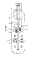
Referring now to FIGS. 10A-10D , one embodiment of an actuator mechanism 1000 for a delivery system having any one of the articulating assemblies described above is illustrated. In the illustrated embodiment, actuator mechanism 1000 employs a ball and socket joint, as described in detail below, such that actuator mechanism 1000 may be manipulated relative to handle 1070 of the delivery system. Actuator mechanism 1000 includes a ball 1010 having a stem that is fixedly connected to the proximal end of handle 1070 by a mounting ring 1060. The spherical portion of ball 1010 is mounted in a housing 1020 so that the housing can pivot in any direction relative to handle 1070. Housing 1020 may include a first portion 1022 and a second portion 1024 secured to one another by fasteners 1030 and 1040 so as to capture ball 1010 therebetween. Locking ring 1050 tightens housing portions 1022, 1024 around ball 1010. In an exemplary configuration, locking ring 1050 may include a thumbscrew or other tightenable fastener for adjusting the pressure exerted by the locking ring on housing portions 1022, 1024. As the fastener is tightened, increased friction created between ball 1010 and housing 1020 will constrain the pivoting movement of the housing relative to the ball so as to retain actuator mechanism 1000 in a desired position relative to handle 1070 and, in turn, the desired orientation of the support shaft relative to the inner shaft.
As can be seen in FIG. 10B , first and second control wires 370, 380 extend through handle 1070 and ball 1010 and are secured to an annular anchor 1080 held in place within complementary recesses formed in housing portions 1022, 1024. FIGS. 10C and 10D further illustrate an exemplary configuration for securing control wires 370, 380 to annular anchor 1080, with the annular anchor removed. Annular anchor 1080 includes a wedge 1085. In an exemplary embodiment, wedge 1085 has a generally conical body with slots 1087 defined thereon. Wedge 1085 is secured to anchor 1080 using a pair of set-screws 1089. A generally cylindrical insert 1090 and a shaft 1100 are longitudinally aligned with one another between handle 1070 and anchor 1080. First and second control wires 370, 380 are guided between handle 1070 and anchor 1080 by grooves formed in the outer surface of insert 1090 and by collinear grooves formed in two supports 1095 mounted on shaft 1100. Control wires 370, 370′, 380, and 380′ further extend through anchor 1080, along slots 1087 and are secured to wedge 1085 at their proximal ends. In an exemplary embodiment, the control wires 370, 370′, 380, and 380′ may be welded to wedge 1085 at their proximal ends. Four arrows A, B, C, D illustrate four principal directions in which housing 1020 may pivot relative to ball 1010 and handle 1070, with corresponding articulating movements of the support shaft, similar to the articulating movements described above.
An embodiment of a medical device delivery system includes an inner shaft having a proximal end and a distal end, a support shaft having a proximal end and a distal end, the support shaft being sized for insertion into the circulatory system of a patient, and an articulating assembly disposed between the inner shaft and the support shaft, the articulating assembly including a first portion at the distal end of the inner shaft and a second portion at the proximal end of the support shaft, the first portion being pivotable relative to the second portion to change the orientation of the support shaft relative to the inner shaft; and/or
the articulating assembly includes a plurality of control wires, movement of one of the control wires proximally causing the second portion of the articulating assembly to pivot relative to the first portion of the articulating assembly; and/or
one of the first and second portions of the articulating assembly is a ball and another of the first and second portions of the articulating assembly is a socket sized to pivotably receive the ball; and/or
the plurality of control wires includes four control wires secured to the second portion of the articulating assembly; and/or
a first two of the control wires lies in a first plane and a second two of the control wires lies in a second plane perpendicular to the first plane; and/or
the delivery system further includes a handle disposed proximally of the inner shaft, and an actuator assembly secured to the handle, the actuator assembly including a housing pivotably mounted to the handle, the plurality of control wires being secured to the housing so that a pivoting movement of the housing relative to the handle pulls at least one of the control wires proximally; and/or
the delivery system includes an anchor for securing the plurality of control wires; and/or
the delivery system includes a wedge mounted within the anchor for securing the plurality of control wires; and/or
the wedge comprises a frustoconical body and the anchor includes a slot configured for accommodating the wedge; and/or
the delivery system includes a retainer secured to the second portion of the articulating assembly and configured to retain a medical device on the support shaft; and/or
the delivery system includes a distal outer sheath configured to cover the inner shaft and the support shaft in a first condition, and movable to a second condition exposing the support shaft, and a proximal outer sheath configured to cover the inner shaft; and/or
the delivery system includes a constricting element mounted on the inner shaft and comprising a generally cylindrical portion and an outwardly flaring portion facing the articulating assembly; and/or
the outwardly flaring portion has a diameter greater than a diameter of the proximal outer sheath; and/or
the inner shaft includes a plurality of notches proximal to the distal end; and/or
one of the first and second portions of the articulating assembly includes a generally concave bearing surface and another of the first and second portions of the articulating assembly includes a ball pivotably engaging the bearing surface, and the delivery system further includes a sheath covering the first and second portions of the articulating assembly and longitudinally constraining the ball relative to the bearing surface.
Another embodiment of the present disclosure includes a medical device delivery system including a support shaft configured to retain a medical device in a collapsed condition and having a proximal end and a distal end, an inner shaft having a proximal end and a distal end, an articulating assembly disposed between the support shaft and the inner shaft, a handle disposed proximally of the inner shaft, an actuator mechanism pivotably secured to the handle, and a plurality of control wires operatively interconnecting the articulating assembly and the actuator mechanism such that pivoting movement of the actuator mechanism causes a corresponding pivoting movement of the support shaft relative to the inner shaft; and/or
the articulating assembly includes a ball pivotably engaged in a socket; and/or
the ball is at the distal end of the inner shaft and the socket is at the proximal end of the support shaft; and/or
the plurality of control wires have first ends secured to the socket; and/or
the delivery system includes a distal outer sheath and a proximal outer sheath for covering the inner shaft, the articulating assembly and the support shaft.
Although the present disclosure has been made with reference to particular embodiments, it is to be understood that these embodiments are merely illustrative of the principles and applications of the present disclosure. It is therefore to be understood that numerous modifications may be made to the illustrative embodiments and that other arrangements may be devised without departing from the spirit and scope of the present disclosure as defined by the present claims.
It will be appreciated that the various dependent claims and the features set forth therein can be combined in different ways than presented in the initial claims. It will also be appreciated that the features described in connection with individual embodiments may be shared with others of the described embodiments.
Claims (20)
1. A medical device delivery system comprising:
an inner shaft having a proximal end and a distal end;
a support shaft having a proximal end and a distal end, the support shaft being sized for insertion into the circulatory system of a patient;
an articulating assembly disposed between the inner shaft and the support shaft, the articulating assembly including a first portion at the distal end of the inner shaft and a second portion at the proximal end of the support shaft, the first portion being pivotable relative to the second portion to change the orientation of the support shaft relative to the inner shaft;
a retainer secured to the second portion of the articulating assembly and configured to retain a medical device on the support shaft between the retainer and the distal end of the support shaft;
a plurality of control wires, movement of one of the control wires proximally causing the second portion of the articulating assembly to pivot relative to the first portion of the articulating assembly;
a handle disposed proximally of the inner shaft;
an actuator assembly secured to the handle, the actuator assembly including a housing pivotably mounted to the handle, the plurality of control wires being secured to the housing so that a pivoting movement of the housing relative to the handle pulls at least one of the control wires proximally;
an anchor for securing the plurality of control wires; and
a wedge mounted within the anchor for securing the plurality of control wires.
2. The delivery system of claim 1 , wherein one of the first and second portions of the articulating assembly is a ball and another of the first and second portions of the articulating assembly is a socket sized to pivotably receive the ball.
3. The delivery system of claim 1 , wherein the plurality of control wires includes four control wires secured to the second portion of the articulating assembly.
4. The delivery system of claim 3 , wherein a first two of the control wires lie in a first plane and a second two of the control wires lie in a second plane perpendicular to the first plane.
5. The delivery system of claim 1 , wherein the wedge comprises a frustoconical body and the anchor includes a slot configured for accommodating the wedge.
6. The delivery system of claim 1 , wherein the inner shaft includes a plurality of notches proximal to the distal end.
7. A medical device delivery system of claim 1 , comprising:
an inner shaft having a proximal end and a distal end;
a support shaft having a proximal end and a distal end, the support shaft being sized for insertion into the circulatory system of a patient;
an articulating assembly disposed between the inner shaft and the support shaft, the articulating assembly including a first portion at the distal end of the inner shaft and a second portion at the proximal end of the support shaft, the first portion being pivotable relative to the second portion to change the orientation of the support shaft relative to the inner shaft;
a retainer secured to the second portion of the articulating assembly and configured to retain a medical device on the support shaft between the retainer and the distal end of the support shaft;
a distal outer sheath configured to cover the inner shaft and the support shaft in a first condition, and movable to a second condition exposing the support shaft; and
a proximal outer sheath configured to cover the inner shaft.
8. The delivery system of claim 7 , further comprising a constricting element mounted on the inner shaft and comprising a generally cylindrical portion and an outwardly flaring portion facing the articulating assembly.
9. The delivery system of claim 8 , wherein the outwardly flaring portion has a diameter greater than a diameter of the proximal outer sheath.
10. The delivery system of claim 7 , wherein the inner shaft includes a plurality of notches proximal to the distal end.
11. The delivery system of claim 7 , wherein the support shaft has a first diameter and the retainer has a second diameter greater than the first diameter.
12. The delivery system of claim 7 , further comprising a plurality of control wires, movement of one of the control wires proximally causing the second portion of the articulating assembly to pivot relative to the first portion of the articulating assembly.
13. The delivery system of 12, further comprising:
a handle disposed proximally of the inner shaft; and
an actuator assembly secured to the handle, the actuator assembly including a housing pivotably mounted to the handle, the plurality of control wires being secured to the housing so that a pivoting movement of the housing relative to the handle pulls at least one of the control wires proximally.
14. The delivery system of claim 13 , further comprising an anchor for securing the plurality of control wires.
15. The delivery system of claim 12 , wherein the plurality of control wires includes four control wires secured to the second portion of the articulating assembly.
16. The delivery system of claim 15 , wherein a first two of the control wires lie in a first plane and a second two of the control wires lie in a second plane perpendicular to the first plane.
17. The delivery system of claim 7 , wherein one of the first and second portions of the articulating assembly is a ball and another of the first and second portions of the articulating assembly is a socket sized to pivotably receive the ball.
18. A medical device delivery system comprising:
an inner shaft having a proximal end and a distal end;
a support shaft having a proximal end and a distal end, the support shaft being sized for insertion into the circulatory system of a patient;
an articulating assembly disposed between the inner shaft and the support shaft, the articulating assembly including a first portion at the distal end of the inner shaft and a second portion at the proximal end of the support shaft, the first portion being pivotable relative to the second portion to change the orientation of the support shaft relative to the inner shaft; and
a retainer secured to the second portion of the articulating assembly and configured to retain a medical device on the support shaft between the retainer and the distal end of the support shaft,
wherein one of the first and second portions of the articulating assembly includes a generally concave bearing surface and another of the first and second portions of the articulating assembly includes a ball pivotably engaging the bearing surface,
the delivery system further including a sheath covering the first and second portions of the articulating assembly and longitudinally constraining the ball relative to the bearing surface.
19. A medical device delivery system comprising:
a support shaft configured to retain a medical device in a collapsed condition and having a proximal end and a distal end;
an inner shaft having a proximal end and a distal end;
an articulating assembly disposed between the support shaft and the inner shaft, the articulating assembly including a ball at the distal end of the inner shaft and a socket at the proximal end of the support shaft, the ball being pivotably engaged in the socket;
a retainer secured to a portion of the articulating assembly and configured to retain the medical device on the support shaft between the retainer and the distal end of the support shaft;
a handle disposed proximally of the inner shaft;
an actuator mechanism pivotably secured to the handle; and
a plurality of control wires operatively interconnecting the articulating assembly and the actuator mechanism such that pivoting movement of the actuator mechanism causes a corresponding pivoting movement of the support shaft relative to the inner shaft, and
wherein the plurality of control wires have first ends secured to the socket.
20. A medical device delivery system comprising:
a support shaft configured to retain a medical device in a collapsed condition and having a proximal end and a distal end;
an inner shaft having a proximal end and a distal end;
an articulating assembly disposed between the support shaft and the inner shaft;
a retainer secured to a portion of the articulating assembly and configured to retain the medical device on the support shaft between the retainer and the distal end of the support shaft;
a handle disposed proximally of the inner shaft;
an actuator mechanism pivotably secured to the handle;
a plurality of control wires operatively interconnecting the articulating assembly and the actuator mechanism such that pivoting movement of the actuator mechanism causes a corresponding pivoting movement of the support shaft relative to the inner shaft; and
a distal outer sheath and a proximal outer sheath for covering the inner shaft, the articulating assembly and the support shaft.
Priority Applications (4)
| Application Number | Priority Date | Filing Date | Title |
|---|---|---|---|
| US14/445,976 US9566153B2 (en) | 2013-09-12 | 2014-07-29 | Alignment of an implantable medical device |
| PCT/US2014/054025 WO2015038393A1 (en) | 2013-09-12 | 2014-09-04 | Alignment of an implantable medical device |
| EP14771694.8A EP3043747B1 (en) | 2013-09-12 | 2014-09-04 | A transcatheter valve prosthesis delivery system |
| US15/400,210 US10500043B2 (en) | 2013-09-12 | 2017-01-06 | Alignment of an implantable medical device |
Applications Claiming Priority (2)
| Application Number | Priority Date | Filing Date | Title |
|---|---|---|---|
| US201361877107P | 2013-09-12 | 2013-09-12 | |
| US14/445,976 US9566153B2 (en) | 2013-09-12 | 2014-07-29 | Alignment of an implantable medical device |
Related Child Applications (1)
| Application Number | Title | Priority Date | Filing Date |
|---|---|---|---|
| US15/400,210 Continuation US10500043B2 (en) | 2013-09-12 | 2017-01-06 | Alignment of an implantable medical device |
Publications (2)
| Publication Number | Publication Date |
|---|---|
| US20150073539A1 US20150073539A1 (en) | 2015-03-12 |
| US9566153B2 true US9566153B2 (en) | 2017-02-14 |
Family
ID=52626312
Family Applications (3)
| Application Number | Title | Priority Date | Filing Date |
|---|---|---|---|
| US14/445,976 Active 2035-01-28 US9566153B2 (en) | 2013-09-12 | 2014-07-29 | Alignment of an implantable medical device |
| US14/445,848 Active 2036-03-18 US10123870B2 (en) | 2013-09-12 | 2014-07-29 | Alignment of an implantable medical device |
| US15/400,210 Active 2035-08-03 US10500043B2 (en) | 2013-09-12 | 2017-01-06 | Alignment of an implantable medical device |
Family Applications After (2)
| Application Number | Title | Priority Date | Filing Date |
|---|---|---|---|
| US14/445,848 Active 2036-03-18 US10123870B2 (en) | 2013-09-12 | 2014-07-29 | Alignment of an implantable medical device |
| US15/400,210 Active 2035-08-03 US10500043B2 (en) | 2013-09-12 | 2017-01-06 | Alignment of an implantable medical device |
Country Status (3)
| Country | Link |
|---|---|
| US (3) | US9566153B2 (en) |
| EP (2) | EP3043747B1 (en) |
| WO (2) | WO2015038393A1 (en) |
Cited By (1)
| Publication number | Priority date | Publication date | Assignee | Title |
|---|---|---|---|---|
| US20170184149A1 (en) * | 2015-12-29 | 2017-06-29 | Leo D. Bernstein & Sons, Inc. | Auto-locking ball joint |
Families Citing this family (50)
| Publication number | Priority date | Publication date | Assignee | Title |
|---|---|---|---|---|
| AU2005211243A1 (en) | 2004-02-03 | 2005-08-18 | Atria Medical Inc. | Device and method for controlling in-vivo pressure |
| US9681948B2 (en) | 2006-01-23 | 2017-06-20 | V-Wave Ltd. | Heart anchor device |
| US9126020B2 (en) | 2007-06-26 | 2015-09-08 | Roxwood Medical, Inc. | Catheter apparatus with telescoping lumen catheters and its use in methods for treating vasculatures |
| US9125683B2 (en) | 2007-06-26 | 2015-09-08 | Roxwood Medical Inc. | Method and apparatus for placing a catheter within a vasculature |
| ES2547490T3 (en) | 2007-06-26 | 2015-10-06 | Roxwood Medical, Inc. | Catheter apparatus and procedures to treat blood vessels |
| US20210161637A1 (en) | 2009-05-04 | 2021-06-03 | V-Wave Ltd. | Shunt for redistributing atrial blood volume |
| US10076403B1 (en) | 2009-05-04 | 2018-09-18 | V-Wave Ltd. | Shunt for redistributing atrial blood volume |
| US9034034B2 (en) | 2010-12-22 | 2015-05-19 | V-Wave Ltd. | Devices for reducing left atrial pressure, and methods of making and using same |
| WO2010128501A1 (en) | 2009-05-04 | 2010-11-11 | V-Wave Ltd. | Device and method for regulating pressure in a heart chamber |
| US8579964B2 (en) | 2010-05-05 | 2013-11-12 | Neovasc Inc. | Transcatheter mitral valve prosthesis |
| US9308087B2 (en) | 2011-04-28 | 2016-04-12 | Neovasc Tiara Inc. | Sequentially deployed transcatheter mitral valve prosthesis |
| US9554897B2 (en) | 2011-04-28 | 2017-01-31 | Neovasc Tiara Inc. | Methods and apparatus for engaging a valve prosthesis with tissue |
| US9629715B2 (en) | 2011-07-28 | 2017-04-25 | V-Wave Ltd. | Devices for reducing left atrial pressure having biodegradable constriction, and methods of making and using same |
| US11135054B2 (en) | 2011-07-28 | 2021-10-05 | V-Wave Ltd. | Interatrial shunts having biodegradable material, and methods of making and using same |
| US9345573B2 (en) | 2012-05-30 | 2016-05-24 | Neovasc Tiara Inc. | Methods and apparatus for loading a prosthesis onto a delivery system |
| JP6381536B2 (en) | 2012-10-22 | 2018-08-29 | ロックスウッド メディカル, インコーポレイテッド | Method and apparatus for aligning a microcatheter within a vascular system |
| US9572665B2 (en) | 2013-04-04 | 2017-02-21 | Neovasc Tiara Inc. | Methods and apparatus for delivering a prosthetic valve to a beating heart |
| US9713696B2 (en) | 2013-05-21 | 2017-07-25 | V-Wave Ltd. | Apparatus and methods for delivering devices for reducing left atrial pressure |
| CN104758092B (en) * | 2015-04-20 | 2018-09-18 | 上海纽脉医疗科技有限公司 | A kind of insertion type artificial cardiac valve transport system |
| WO2016178171A1 (en) | 2015-05-07 | 2016-11-10 | The Medical Research Infrastructure And Health Services Fund Of The Tel-Aviv Medical Center | Temporary interatrial shunts |
| US10596354B2 (en) | 2015-09-25 | 2020-03-24 | Mark Taber | Guide wires, catheters, and guide wire catheter systems and methods |
| DE202017007326U1 (en) | 2016-01-29 | 2020-10-20 | Neovasc Tiara Inc. | Valve prosthesis to prevent flow obstruction |
| AU2017240507B2 (en) | 2016-03-31 | 2020-01-30 | Medtronic Vascular Inc. | Expandable introducer sheath having a steering mechanism |
| US20170340460A1 (en) | 2016-05-31 | 2017-11-30 | V-Wave Ltd. | Systems and methods for making encapsulated hourglass shaped stents |
| US10835394B2 (en) | 2016-05-31 | 2020-11-17 | V-Wave, Ltd. | Systems and methods for making encapsulated hourglass shaped stents |
| CN109996581B (en) | 2016-11-21 | 2021-10-15 | 内奥瓦斯克迪亚拉公司 | Methods and systems for rapid retrieval of transcatheter heart valve delivery systems |
| US10433993B2 (en) | 2017-01-20 | 2019-10-08 | Medtronic Vascular, Inc. | Valve prosthesis having a radially-expandable sleeve integrated thereon for delivery and prevention of paravalvular leakage |
| US10716667B2 (en) | 2017-01-20 | 2020-07-21 | Medtronic Vascular, Inc. | Transcatheter delivery systems and delivery catheters for prosthetic mitral valve delivery, and methods for prosthetic mitral valve delivery using a retrograde approach |
| EP3589238A1 (en) | 2017-03-03 | 2020-01-08 | V-Wave Ltd. | Shunt for redistributing atrial blood volume |
| US11291807B2 (en) | 2017-03-03 | 2022-04-05 | V-Wave Ltd. | Asymmetric shunt for redistributing atrial blood volume |
| US10813761B2 (en) * | 2017-05-23 | 2020-10-27 | Harmony Development Group, Inc. | Tethered implantable device having a vortical intracardiac velocity adjusting balloon |
| WO2019006152A1 (en) | 2017-06-28 | 2019-01-03 | Harmony Development Group, Inc. | A force transducting inflatable implant system including a dual force annular transduction implant |
| US10813757B2 (en) | 2017-07-06 | 2020-10-27 | Edwards Lifesciences Corporation | Steerable rail delivery system |
| WO2019040781A1 (en) * | 2017-08-24 | 2019-02-28 | Medtronic Vascular, Inc. | Transseptal delivery systems having a deflecting segment and methods of use |
| CN111263622A (en) | 2017-08-25 | 2020-06-09 | 内奥瓦斯克迪亚拉公司 | Sequentially deployed transcatheter mitral valve prosthesis |
| US11006939B2 (en) * | 2017-12-08 | 2021-05-18 | Tendyne Holdings, Inc. | Introducer sheath with seal and methods of using the same |
| WO2019142152A1 (en) | 2018-01-20 | 2019-07-25 | V-Wave Ltd. | Devices and methods for providing passage between heart chambers |
| US10898698B1 (en) | 2020-05-04 | 2021-01-26 | V-Wave Ltd. | Devices with dimensions that can be reduced and increased in vivo, and methods of making and using the same |
| US11458287B2 (en) | 2018-01-20 | 2022-10-04 | V-Wave Ltd. | Devices with dimensions that can be reduced and increased in vivo, and methods of making and using the same |
| US11167122B2 (en) | 2018-03-05 | 2021-11-09 | Harmony Development Group, Inc. | Force transducting implant system for the mitigation of atrioventricular pressure gradient loss and the restoration of healthy ventricular geometry |
| EP3876870B1 (en) | 2018-11-08 | 2023-12-20 | Neovasc Tiara Inc. | Ventricular deployment of a transcatheter mitral valve prosthesis |
| JP7438236B2 (en) | 2019-04-01 | 2024-02-26 | ニオバスク ティアラ インコーポレイテッド | Controllably deployable prosthetic valve |
| US11612385B2 (en) | 2019-04-03 | 2023-03-28 | V-Wave Ltd. | Systems and methods for delivering implantable devices across an atrial septum |
| CA3136334A1 (en) | 2019-04-10 | 2020-10-15 | Neovasc Tiara Inc. | Prosthetic valve with natural blood flow |
| CN114096205A (en) | 2019-05-20 | 2022-02-25 | V-波有限责任公司 | System and method for creating room shunt tubes |
| AU2020279750B2 (en) | 2019-05-20 | 2023-07-13 | Neovasc Tiara Inc. | Introducer with hemostasis mechanism |
| AU2020295566B2 (en) | 2019-06-20 | 2023-07-20 | Neovasc Tiara Inc. | Low profile prosthetic mitral valve |
| CN112438824A (en) * | 2019-09-03 | 2021-03-05 | 上海微创心通医疗科技有限公司 | Medical implant delivery device |
| US11234702B1 (en) | 2020-11-13 | 2022-02-01 | V-Wave Ltd. | Interatrial shunt having physiologic sensor |
| US11813386B2 (en) | 2022-04-14 | 2023-11-14 | V-Wave Ltd. | Interatrial shunt with expanded neck region |
Citations (101)
| Publication number | Priority date | Publication date | Assignee | Title |
|---|---|---|---|---|
| US3384088A (en) | 1965-07-02 | 1968-05-21 | Miseo Anthony | Obstetrical forceps |
| US3657744A (en) | 1970-05-08 | 1972-04-25 | Univ Minnesota | Method for fixing prosthetic implants in a living body |
| US3724238A (en) | 1970-03-17 | 1973-04-03 | Fives Lille Cail | Rotor mounting |
| US4423730A (en) | 1982-03-01 | 1984-01-03 | Shelhigh Inc. | Atriotomy button and implantation device |
| US4641657A (en) | 1985-02-08 | 1987-02-10 | University Patents, Inc. | Probe swivel mechanism |
| US5368592A (en) | 1992-04-13 | 1994-11-29 | Ep Technologies, Inc. | Articulated systems for cardiac ablation |
| US5372587A (en) | 1989-01-09 | 1994-12-13 | Pilot Cariovascular Systems, Inc. | Steerable medical device |
| US5405344A (en) * | 1993-09-30 | 1995-04-11 | Ethicon, Inc. | Articulable socket joint assembly for an endoscopic instrument for surgical fastner track therefor |
| WO1995010317A1 (en) | 1993-10-15 | 1995-04-20 | Kirkman Thomas R | Apparatus and method for retaining a catheter |
| US5507725A (en) | 1992-12-23 | 1996-04-16 | Angeion Corporation | Steerable catheter |
| US5549594A (en) | 1991-07-02 | 1996-08-27 | Ethicon, Inc. | Sealing cap for guide tubes or reducing sleeves for the introduction of surgical instruments |
| US5569270A (en) | 1994-12-13 | 1996-10-29 | Weng; Edward E. | Laparoscopic surgical instrument |
| US5575799A (en) | 1995-03-30 | 1996-11-19 | United States Surgical Corporation | Articulating surgical apparatus |
| US5749881A (en) | 1993-10-20 | 1998-05-12 | Applied Medical Resources | Laparoscopic surgical clamp |
| US5843167A (en) | 1993-04-22 | 1998-12-01 | C. R. Bard, Inc. | Method and apparatus for recapture of hooked endoprosthesis |
| FR2765098A1 (en) | 1997-06-25 | 1998-12-31 | Jean Noel Bernard | APPLIANCE FOR LAYING AND RECOVERING PARTS SUCH AS ENDOPROTHESES |
| US5868685A (en) | 1995-11-14 | 1999-02-09 | Devices For Vascular Intervention | Articulated guidewire |
| US5924424A (en) | 1993-02-22 | 1999-07-20 | Heartport, Inc. | Method and apparatus for thoracoscopic intracardiac procedures |
| US5968068A (en) | 1996-09-12 | 1999-10-19 | Baxter International Inc. | Endovascular delivery system |
| US6077297A (en) | 1993-11-04 | 2000-06-20 | C. R. Bard, Inc. | Non-migrating vascular prosthesis and minimally invasive placement system therefor |
| US6183432B1 (en) | 1997-11-13 | 2001-02-06 | Lumend, Inc. | Guidewire and catheter with rotating and reciprocating symmetrical or asymmetrical distal tip |
| EP1129744A1 (en) | 1993-12-03 | 2001-09-05 | Heartport, Inc. | Cardiopulmonary bypass system for closed-chest intervention |
| US6306141B1 (en) | 1983-10-14 | 2001-10-23 | Medtronic, Inc. | Medical devices incorporating SIM alloy elements |
| EP1157673A2 (en) | 2000-05-26 | 2001-11-28 | Variomed AG | Stent, position's element and delivery catheter |
| US6464684B1 (en) | 1998-09-09 | 2002-10-15 | Scimed Life Systems, Inc. | Catheter having regions of differing braid densities and methods of manufacture therefor |
| US20030050694A1 (en) | 2001-09-13 | 2003-03-13 | Jibin Yang | Methods and apparatuses for deploying minimally-invasive heart valves |
| US6623518B2 (en) | 2001-02-26 | 2003-09-23 | Ev3 Peripheral, Inc. | Implant delivery system with interlock |
| US20030233108A1 (en) | 2002-06-12 | 2003-12-18 | Scimed Life Systems, Inc. | Endoscopic suture instrument |
| US6743239B1 (en) | 2000-05-25 | 2004-06-01 | St. Jude Medical, Inc. | Devices with a bendable tip for medical procedures |
| US20040210304A1 (en) | 1999-11-17 | 2004-10-21 | Corevalve, S.A. | Prosthetic valve for transluminal delivery |
| US6814746B2 (en) | 2002-11-01 | 2004-11-09 | Ev3 Peripheral, Inc. | Implant delivery system with marker interlock |
| US6830584B1 (en) | 1999-11-17 | 2004-12-14 | Jacques Seguin | Device for replacing a cardiac valve by percutaneous route |
| US20050137622A1 (en) | 2003-12-23 | 2005-06-23 | Scimed Life Systems, Inc. | Catheter with distal occlusion |
| US20050137697A1 (en) | 2003-12-23 | 2005-06-23 | Amr Salahieh | Leaflet engagement elements and methods for use thereof |
| US20050137695A1 (en) | 2003-12-23 | 2005-06-23 | Sadra Medical | Replacement valve and anchor |
| US20050165352A1 (en) | 2004-01-23 | 2005-07-28 | Scimed Life Systems, Inc. | Stent delivery catheter |
| US20050177138A1 (en) | 2002-06-24 | 2005-08-11 | Dubrovsky Arkady V. | Remote controlled device for tool rotating |
| US20050222604A1 (en) | 2004-03-31 | 2005-10-06 | Cook Incorporated | Self centering delivery catheter |
| US20060058872A1 (en) | 2003-12-23 | 2006-03-16 | Amr Salahieh | Methods and apparatus for endovascular heart valve replacement comprising tissue grasping elements |
| US7018406B2 (en) | 1999-11-17 | 2006-03-28 | Corevalve Sa | Prosthetic valve for transluminal delivery |
| US20060074484A1 (en) | 2004-10-02 | 2006-04-06 | Huber Christoph H | Methods and devices for repair or replacement of heart valves or adjacent tissue without the need for full cardiopulmonary support |
| US20060100687A1 (en) * | 2004-11-10 | 2006-05-11 | Creganna Technologies Limited | Elongate tubular member for use in medical device shafts |
| US20060106415A1 (en) | 2004-11-12 | 2006-05-18 | Shlomo Gabbay | Apparatus to facilitate implantation |
| US20060142848A1 (en) | 2000-09-12 | 2006-06-29 | Shlomo Gabbay | Extra-anatomic aortic valve placement |
| US20060167468A1 (en) | 2004-11-12 | 2006-07-27 | Shlomo Gabbay | Implantation system and method for loading an implanter with a prosthesis |
| US20060235502A1 (en) | 2005-04-18 | 2006-10-19 | Medtronic Vascular, Inc. | Intravascular deployment device with improved deployment capability |
| US20060259120A1 (en) | 2005-05-12 | 2006-11-16 | Ev3, Inc. | Implant delivery system with interlocked RX port orientation |
| WO2006138173A2 (en) | 2005-06-13 | 2006-12-28 | Edwards Lifesciences Corporation | Heart valve delivery system |
| US20070010876A1 (en) | 2003-12-23 | 2007-01-11 | Amr Salahieh | Externally Expandable Heart Valve Anchor and Method |
| US20070027534A1 (en) | 2005-07-27 | 2007-02-01 | Bjarne Bergheim | Methods and systems for cardiac valve delivery |
| US20070043259A1 (en) | 2000-04-03 | 2007-02-22 | Ross Jaffe | Endoscope Having a Guide Tube |
| US20070043435A1 (en) | 1999-11-17 | 2007-02-22 | Jacques Seguin | Non-cylindrical prosthetic valve system for transluminal delivery |
| US20070055358A1 (en) | 2005-08-22 | 2007-03-08 | Krolik Jeffrey A | Axially compressible flared stents and apparatus and methods for delivering them |
| US20070073391A1 (en) | 2005-09-28 | 2007-03-29 | Henry Bourang | System and method for delivering a mitral valve repair device |
| US20070088431A1 (en) | 2005-10-18 | 2007-04-19 | Henry Bourang | Heart valve delivery system with valve catheter |
| US20070112422A1 (en) | 2005-11-16 | 2007-05-17 | Mark Dehdashtian | Transapical heart valve delivery system and method |
| WO2007071436A2 (en) | 2005-12-22 | 2007-06-28 | Symetis Sa | Stent-valves for valve replacement and associated methods and systems for surgery |
| US20070162100A1 (en) | 2006-01-10 | 2007-07-12 | Shlomo Gabbay | System and method for loading implanter with prosthesis |
| US20070168013A1 (en) | 2006-01-19 | 2007-07-19 | Myles Douglas | Vascular graft and deployment system |
| US20070203575A1 (en) | 2006-02-27 | 2007-08-30 | Cardiacmd, Inc., A California Corporation | Methods and devices for delivery of prosthetic heart valves and other prosthetics |
| US20070239271A1 (en) | 2006-04-10 | 2007-10-11 | Than Nguyen | Systems and methods for loading a prosthesis onto a minimally invasive delivery system |
| US20070244552A1 (en) | 2003-12-23 | 2007-10-18 | Amr Salahieh | Assessing the location and performance of replacement heart valves |
| US20070250113A1 (en) * | 2003-05-23 | 2007-10-25 | Hegeman David E | Tool with articulation lock |
| US7311730B2 (en) | 2004-02-13 | 2007-12-25 | Shlomo Gabbay | Support apparatus and heart valve prosthesis for sutureless implantation |
| US20080065122A1 (en) | 2003-10-10 | 2008-03-13 | Stack Richard S | Restrictive and/or obstructive implant system for inducing weight loss |
| US20080071369A1 (en) | 2006-09-19 | 2008-03-20 | Yosi Tuval | Valve fixation member having engagement arms |
| WO2008070797A2 (en) | 2006-12-06 | 2008-06-12 | Medtronic Corevalve, Inc. | System and method for transapical delivery of an annulus anchored self-expanding valve |
| US20080147160A1 (en) | 2006-12-19 | 2008-06-19 | Sorin Biomedical Cardio S.R.L. | System for in situ positioning of cardiac valve prostheses without occluding blood flow |
| US20080147182A1 (en) | 2006-12-19 | 2008-06-19 | Sorin Biomedica Cardio S.R.L. | Instrument and method for in situ deployment of cardiac valve prostheses |
| US20080228223A1 (en) | 2007-03-14 | 2008-09-18 | St. Jude Medical, Inc. | Heart valve chordae replacement methods and apparatus |
| US20090054975A1 (en) | 2004-02-06 | 2009-02-26 | Children's Medical Center Corporation | Deployment device for cardiac surgery |
| US20090062606A1 (en) | 2007-08-31 | 2009-03-05 | Hoya Corporation | Endoscope guiding tube device |
| US20090062839A1 (en) | 2007-08-31 | 2009-03-05 | Cook Incorporated | Barbed stent vascular occlusion device |
| US7510572B2 (en) | 2000-09-12 | 2009-03-31 | Shlomo Gabbay | Implantation system for delivery of a heart valve prosthesis |
| US7637905B2 (en) | 2003-01-15 | 2009-12-29 | Usgi Medical, Inc. | Endoluminal tool deployment system |
| US20100004740A1 (en) | 1999-11-17 | 2010-01-07 | Jacques Seguin | Prosthetic Valve for Transluminal Delivery |
| US7682390B2 (en) | 2001-07-31 | 2010-03-23 | Medtronic, Inc. | Assembly for setting a valve prosthesis in a corporeal duct |
| WO2010051025A1 (en) | 2008-10-30 | 2010-05-06 | St. Jude Medical, Inc. | Collapsible/expandable prosthetic heart valve delivery system and methods |
| WO2010087975A1 (en) | 2009-01-30 | 2010-08-05 | St. Jude Medical, Inc. | Transapical mini-introducer homeostasis valve and punch |
| US20100204708A1 (en) | 2010-02-23 | 2010-08-12 | Sanjiv Sharma | Carotid guiding catheter (sheath) for carotid percutaneous intervention/stenting with internal fixation device to prevent migration of the Carotid guiding catheter (sheath) |
| US20100228191A1 (en) | 2009-03-05 | 2010-09-09 | Hansen Medical, Inc. | Lockable support assembly and method |
| US20100228152A1 (en) | 2006-08-18 | 2010-09-09 | Fisher William T | Catheter for conducting a procedure within a lumen, duct or organ of a living being |
| US7811277B2 (en) | 2004-09-30 | 2010-10-12 | Boston Scientific Scimed, Inc. | Steerable device and system |
| WO2010127162A1 (en) | 2009-04-29 | 2010-11-04 | Hansen Medical, Inc. | Flexible and steerable elongate instruments with shape control and support elements |
| US20100286768A1 (en) | 2008-01-16 | 2010-11-11 | Alkhatib Yousef F | Delivery and retrieval systems for collapsible/expandable prosthetic heart valves |
| US20100298931A1 (en) | 2009-04-15 | 2010-11-25 | Arshad Quadri | Vascular implant and delivery system |
| US20110098800A1 (en) | 2008-07-15 | 2011-04-28 | St. Jude Medical, Inc | Axially anchoring collapsible and re-expandable prosthetic heart valves for various disease states |
| US20110207999A1 (en) | 2010-02-24 | 2011-08-25 | Nobuyuki Torisawa | Torque transmission device having control wire |
| US20110224678A1 (en) | 2006-03-23 | 2011-09-15 | Shlomo Gabbay | Method and implantation system for implanting a cardiovascular prosthesis |
| US20110245917A1 (en) | 2010-03-30 | 2011-10-06 | Medtronic, Inc. | Transcatheter Prosthetic Heart Valve Delivery System With Recapturing Feature and Method |
| US20120078350A1 (en) | 2010-07-15 | 2012-03-29 | St. Jude Medical, Inc. | Retainers for transcatheter heart valve delivery systems |
| WO2012112469A2 (en) | 2011-02-15 | 2012-08-23 | Medivalve Ltd. | Percutaneous positioning device |
| US20120303111A1 (en) | 2010-07-23 | 2012-11-29 | Medtronic, Inc. | Attachment Mechanism for Stent Release |
| US20130060328A1 (en) | 2011-09-06 | 2013-03-07 | Medtronic, Inc. | Transcatheter Balloon-Assisted Mitral Valve Navigation Device and Method |
| US20130103047A1 (en) | 2011-10-24 | 2013-04-25 | Medtronic, Inc. | Delivery system assemblies and associated methods for implantable medical devices |
| US20130274870A1 (en) * | 2010-09-24 | 2013-10-17 | Symetis Sa | Stent Valve, Delivery Apparatus and Method Therefor |
| US20130297012A1 (en) | 2012-05-04 | 2013-11-07 | St. Jude Medical, Cardiology Division, Inc. | Delivery system deflection mechanism |
| US20130297102A1 (en) | 2012-05-03 | 2013-11-07 | Honeywell International Inc. | Electric taxi auto-guidance and control system |
| WO2013166355A1 (en) | 2012-05-04 | 2013-11-07 | St. Jude Medical, Cardiology Division, Inc. | Hypotube shaft with articulation mechanism |
| WO2014130160A1 (en) | 2013-02-21 | 2014-08-28 | St. Jude Medical, Cardiology Division, Inc. | Transapical passive articulation delivery system design |
| US9227990B2 (en) | 2012-10-29 | 2016-01-05 | Cipla Limited | Antiviral phosphonate analogues and process for preparation thereof |
Family Cites Families (6)
| Publication number | Priority date | Publication date | Assignee | Title |
|---|---|---|---|---|
| US5928260A (en) * | 1997-07-10 | 1999-07-27 | Scimed Life Systems, Inc. | Removable occlusion system for aneurysm neck |
| US20070123925A1 (en) * | 2005-11-28 | 2007-05-31 | Medtronic Vascular, Inc. | Pre-curved guiding catheter with mechanically actuated anchor |
| CA2670589A1 (en) * | 2007-02-05 | 2008-08-14 | Boston Scientific Limited | Percutaneous valve, system and method |
| US20100057000A1 (en) * | 2008-08-27 | 2010-03-04 | Cook Incorporated | Malecot with textile cover |
| US20120020937A1 (en) * | 2009-04-28 | 2012-01-26 | Anterogen Co., Ltd. | Autologous and allogenic adipose-derived stromal stem cell composition for treating fistulas |
| US20120209375A1 (en) * | 2011-02-11 | 2012-08-16 | Gilbert Madrid | Stability device for use with percutaneous delivery systems |
-
2014
- 2014-07-29 US US14/445,976 patent/US9566153B2/en active Active
- 2014-07-29 US US14/445,848 patent/US10123870B2/en active Active
- 2014-09-04 WO PCT/US2014/054025 patent/WO2015038393A1/en active Application Filing
- 2014-09-04 EP EP14771694.8A patent/EP3043747B1/en active Active
- 2014-09-11 WO PCT/US2014/055053 patent/WO2015038688A1/en active Application Filing
- 2014-09-11 EP EP14771735.9A patent/EP3043748B1/en active Active
-
2017
- 2017-01-06 US US15/400,210 patent/US10500043B2/en active Active
Patent Citations (106)
| Publication number | Priority date | Publication date | Assignee | Title |
|---|---|---|---|---|
| US3384088A (en) | 1965-07-02 | 1968-05-21 | Miseo Anthony | Obstetrical forceps |
| US3724238A (en) | 1970-03-17 | 1973-04-03 | Fives Lille Cail | Rotor mounting |
| US3657744A (en) | 1970-05-08 | 1972-04-25 | Univ Minnesota | Method for fixing prosthetic implants in a living body |
| US4423730A (en) | 1982-03-01 | 1984-01-03 | Shelhigh Inc. | Atriotomy button and implantation device |
| US6306141B1 (en) | 1983-10-14 | 2001-10-23 | Medtronic, Inc. | Medical devices incorporating SIM alloy elements |
| US4641657A (en) | 1985-02-08 | 1987-02-10 | University Patents, Inc. | Probe swivel mechanism |
| US5372587A (en) | 1989-01-09 | 1994-12-13 | Pilot Cariovascular Systems, Inc. | Steerable medical device |
| US5549594A (en) | 1991-07-02 | 1996-08-27 | Ethicon, Inc. | Sealing cap for guide tubes or reducing sleeves for the introduction of surgical instruments |
| US5368592A (en) | 1992-04-13 | 1994-11-29 | Ep Technologies, Inc. | Articulated systems for cardiac ablation |
| US5507725A (en) | 1992-12-23 | 1996-04-16 | Angeion Corporation | Steerable catheter |
| US5924424A (en) | 1993-02-22 | 1999-07-20 | Heartport, Inc. | Method and apparatus for thoracoscopic intracardiac procedures |
| US5843167A (en) | 1993-04-22 | 1998-12-01 | C. R. Bard, Inc. | Method and apparatus for recapture of hooked endoprosthesis |
| US5405344A (en) * | 1993-09-30 | 1995-04-11 | Ethicon, Inc. | Articulable socket joint assembly for an endoscopic instrument for surgical fastner track therefor |
| WO1995010317A1 (en) | 1993-10-15 | 1995-04-20 | Kirkman Thomas R | Apparatus and method for retaining a catheter |
| US5749881A (en) | 1993-10-20 | 1998-05-12 | Applied Medical Resources | Laparoscopic surgical clamp |
| US6077297A (en) | 1993-11-04 | 2000-06-20 | C. R. Bard, Inc. | Non-migrating vascular prosthesis and minimally invasive placement system therefor |
| EP1129744A1 (en) | 1993-12-03 | 2001-09-05 | Heartport, Inc. | Cardiopulmonary bypass system for closed-chest intervention |
| US5569270A (en) | 1994-12-13 | 1996-10-29 | Weng; Edward E. | Laparoscopic surgical instrument |
| US5575799A (en) | 1995-03-30 | 1996-11-19 | United States Surgical Corporation | Articulating surgical apparatus |
| US5868685A (en) | 1995-11-14 | 1999-02-09 | Devices For Vascular Intervention | Articulated guidewire |
| US5968068A (en) | 1996-09-12 | 1999-10-19 | Baxter International Inc. | Endovascular delivery system |
| FR2765098A1 (en) | 1997-06-25 | 1998-12-31 | Jean Noel Bernard | APPLIANCE FOR LAYING AND RECOVERING PARTS SUCH AS ENDOPROTHESES |
| US6183432B1 (en) | 1997-11-13 | 2001-02-06 | Lumend, Inc. | Guidewire and catheter with rotating and reciprocating symmetrical or asymmetrical distal tip |
| US6464684B1 (en) | 1998-09-09 | 2002-10-15 | Scimed Life Systems, Inc. | Catheter having regions of differing braid densities and methods of manufacture therefor |
| US7018406B2 (en) | 1999-11-17 | 2006-03-28 | Corevalve Sa | Prosthetic valve for transluminal delivery |
| US20100004740A1 (en) | 1999-11-17 | 2010-01-07 | Jacques Seguin | Prosthetic Valve for Transluminal Delivery |
| US20070043435A1 (en) | 1999-11-17 | 2007-02-22 | Jacques Seguin | Non-cylindrical prosthetic valve system for transluminal delivery |
| US20040210304A1 (en) | 1999-11-17 | 2004-10-21 | Corevalve, S.A. | Prosthetic valve for transluminal delivery |
| US6830584B1 (en) | 1999-11-17 | 2004-12-14 | Jacques Seguin | Device for replacing a cardiac valve by percutaneous route |
| US20070043259A1 (en) | 2000-04-03 | 2007-02-22 | Ross Jaffe | Endoscope Having a Guide Tube |
| US6743239B1 (en) | 2000-05-25 | 2004-06-01 | St. Jude Medical, Inc. | Devices with a bendable tip for medical procedures |
| EP1157673A2 (en) | 2000-05-26 | 2001-11-28 | Variomed AG | Stent, position's element and delivery catheter |
| US7510572B2 (en) | 2000-09-12 | 2009-03-31 | Shlomo Gabbay | Implantation system for delivery of a heart valve prosthesis |
| US7803185B2 (en) | 2000-09-12 | 2010-09-28 | Shlomo Gabbay | Method of implantation of a heart valve prosthesis through a tubular catheter |
| US20060142848A1 (en) | 2000-09-12 | 2006-06-29 | Shlomo Gabbay | Extra-anatomic aortic valve placement |
| US6623518B2 (en) | 2001-02-26 | 2003-09-23 | Ev3 Peripheral, Inc. | Implant delivery system with interlock |
| US7682390B2 (en) | 2001-07-31 | 2010-03-23 | Medtronic, Inc. | Assembly for setting a valve prosthesis in a corporeal duct |
| US20030050694A1 (en) | 2001-09-13 | 2003-03-13 | Jibin Yang | Methods and apparatuses for deploying minimally-invasive heart valves |
| US20030233108A1 (en) | 2002-06-12 | 2003-12-18 | Scimed Life Systems, Inc. | Endoscopic suture instrument |
| US7300431B2 (en) | 2002-06-24 | 2007-11-27 | Arkady Veniaminovich Dubrovsky | Remote controlled device for tool rotating |
| US20050177138A1 (en) | 2002-06-24 | 2005-08-11 | Dubrovsky Arkady V. | Remote controlled device for tool rotating |
| US6814746B2 (en) | 2002-11-01 | 2004-11-09 | Ev3 Peripheral, Inc. | Implant delivery system with marker interlock |
| US7637905B2 (en) | 2003-01-15 | 2009-12-29 | Usgi Medical, Inc. | Endoluminal tool deployment system |
| US20070250113A1 (en) * | 2003-05-23 | 2007-10-25 | Hegeman David E | Tool with articulation lock |
| US20080065122A1 (en) | 2003-10-10 | 2008-03-13 | Stack Richard S | Restrictive and/or obstructive implant system for inducing weight loss |
| US20050137697A1 (en) | 2003-12-23 | 2005-06-23 | Amr Salahieh | Leaflet engagement elements and methods for use thereof |
| US20050137622A1 (en) | 2003-12-23 | 2005-06-23 | Scimed Life Systems, Inc. | Catheter with distal occlusion |
| US20070244552A1 (en) | 2003-12-23 | 2007-10-18 | Amr Salahieh | Assessing the location and performance of replacement heart valves |
| US20070010876A1 (en) | 2003-12-23 | 2007-01-11 | Amr Salahieh | Externally Expandable Heart Valve Anchor and Method |
| US20060058872A1 (en) | 2003-12-23 | 2006-03-16 | Amr Salahieh | Methods and apparatus for endovascular heart valve replacement comprising tissue grasping elements |
| US20050137695A1 (en) | 2003-12-23 | 2005-06-23 | Sadra Medical | Replacement valve and anchor |
| US20050165352A1 (en) | 2004-01-23 | 2005-07-28 | Scimed Life Systems, Inc. | Stent delivery catheter |
| US20090054975A1 (en) | 2004-02-06 | 2009-02-26 | Children's Medical Center Corporation | Deployment device for cardiac surgery |
| US7311730B2 (en) | 2004-02-13 | 2007-12-25 | Shlomo Gabbay | Support apparatus and heart valve prosthesis for sutureless implantation |
| US20050222604A1 (en) | 2004-03-31 | 2005-10-06 | Cook Incorporated | Self centering delivery catheter |
| US7811277B2 (en) | 2004-09-30 | 2010-10-12 | Boston Scientific Scimed, Inc. | Steerable device and system |
| US20060074484A1 (en) | 2004-10-02 | 2006-04-06 | Huber Christoph H | Methods and devices for repair or replacement of heart valves or adjacent tissue without the need for full cardiopulmonary support |
| US20060100687A1 (en) * | 2004-11-10 | 2006-05-11 | Creganna Technologies Limited | Elongate tubular member for use in medical device shafts |
| US20060106415A1 (en) | 2004-11-12 | 2006-05-18 | Shlomo Gabbay | Apparatus to facilitate implantation |
| US20060167468A1 (en) | 2004-11-12 | 2006-07-27 | Shlomo Gabbay | Implantation system and method for loading an implanter with a prosthesis |
| US20060235502A1 (en) | 2005-04-18 | 2006-10-19 | Medtronic Vascular, Inc. | Intravascular deployment device with improved deployment capability |
| EP1716822A1 (en) | 2005-04-18 | 2006-11-02 | Medtronic Vascular, Inc. | Intravascular deployment device with improved deployment capability |
| US20060259120A1 (en) | 2005-05-12 | 2006-11-16 | Ev3, Inc. | Implant delivery system with interlocked RX port orientation |
| WO2006138173A2 (en) | 2005-06-13 | 2006-12-28 | Edwards Lifesciences Corporation | Heart valve delivery system |
| US20070027534A1 (en) | 2005-07-27 | 2007-02-01 | Bjarne Bergheim | Methods and systems for cardiac valve delivery |
| US20070073376A1 (en) | 2005-08-22 | 2007-03-29 | Krolik Jeffrey A | Steep-taper flared stents and apparatus and methods for delivering them |
| US20070055358A1 (en) | 2005-08-22 | 2007-03-08 | Krolik Jeffrey A | Axially compressible flared stents and apparatus and methods for delivering them |
| EP1926455A2 (en) | 2005-09-20 | 2008-06-04 | Sadra Medical, Inc. | Methods and apparatus for endovascular heart valve replacement comprising tissue grasping elements |
| US20070073391A1 (en) | 2005-09-28 | 2007-03-29 | Henry Bourang | System and method for delivering a mitral valve repair device |
| US20070088431A1 (en) | 2005-10-18 | 2007-04-19 | Henry Bourang | Heart valve delivery system with valve catheter |
| US20070112422A1 (en) | 2005-11-16 | 2007-05-17 | Mark Dehdashtian | Transapical heart valve delivery system and method |
| WO2007071436A2 (en) | 2005-12-22 | 2007-06-28 | Symetis Sa | Stent-valves for valve replacement and associated methods and systems for surgery |
| US20070162100A1 (en) | 2006-01-10 | 2007-07-12 | Shlomo Gabbay | System and method for loading implanter with prosthesis |
| US20070168013A1 (en) | 2006-01-19 | 2007-07-19 | Myles Douglas | Vascular graft and deployment system |
| US20070203575A1 (en) | 2006-02-27 | 2007-08-30 | Cardiacmd, Inc., A California Corporation | Methods and devices for delivery of prosthetic heart valves and other prosthetics |
| US20110224678A1 (en) | 2006-03-23 | 2011-09-15 | Shlomo Gabbay | Method and implantation system for implanting a cardiovascular prosthesis |
| US20070239271A1 (en) | 2006-04-10 | 2007-10-11 | Than Nguyen | Systems and methods for loading a prosthesis onto a minimally invasive delivery system |
| US20100228152A1 (en) | 2006-08-18 | 2010-09-09 | Fisher William T | Catheter for conducting a procedure within a lumen, duct or organ of a living being |
| US20080071369A1 (en) | 2006-09-19 | 2008-03-20 | Yosi Tuval | Valve fixation member having engagement arms |
| WO2008070797A2 (en) | 2006-12-06 | 2008-06-12 | Medtronic Corevalve, Inc. | System and method for transapical delivery of an annulus anchored self-expanding valve |
| US20080147182A1 (en) | 2006-12-19 | 2008-06-19 | Sorin Biomedica Cardio S.R.L. | Instrument and method for in situ deployment of cardiac valve prostheses |
| US20080147160A1 (en) | 2006-12-19 | 2008-06-19 | Sorin Biomedical Cardio S.R.L. | System for in situ positioning of cardiac valve prostheses without occluding blood flow |
| US20080228223A1 (en) | 2007-03-14 | 2008-09-18 | St. Jude Medical, Inc. | Heart valve chordae replacement methods and apparatus |
| US20090062839A1 (en) | 2007-08-31 | 2009-03-05 | Cook Incorporated | Barbed stent vascular occlusion device |
| US20090062606A1 (en) | 2007-08-31 | 2009-03-05 | Hoya Corporation | Endoscope guiding tube device |
| US20100286768A1 (en) | 2008-01-16 | 2010-11-11 | Alkhatib Yousef F | Delivery and retrieval systems for collapsible/expandable prosthetic heart valves |
| US20110098800A1 (en) | 2008-07-15 | 2011-04-28 | St. Jude Medical, Inc | Axially anchoring collapsible and re-expandable prosthetic heart valves for various disease states |
| WO2010051025A1 (en) | 2008-10-30 | 2010-05-06 | St. Jude Medical, Inc. | Collapsible/expandable prosthetic heart valve delivery system and methods |
| WO2010087975A1 (en) | 2009-01-30 | 2010-08-05 | St. Jude Medical, Inc. | Transapical mini-introducer homeostasis valve and punch |
| US20100228191A1 (en) | 2009-03-05 | 2010-09-09 | Hansen Medical, Inc. | Lockable support assembly and method |
| US20100298931A1 (en) | 2009-04-15 | 2010-11-25 | Arshad Quadri | Vascular implant and delivery system |
| WO2010127162A1 (en) | 2009-04-29 | 2010-11-04 | Hansen Medical, Inc. | Flexible and steerable elongate instruments with shape control and support elements |
| US20100204708A1 (en) | 2010-02-23 | 2010-08-12 | Sanjiv Sharma | Carotid guiding catheter (sheath) for carotid percutaneous intervention/stenting with internal fixation device to prevent migration of the Carotid guiding catheter (sheath) |
| US20110207999A1 (en) | 2010-02-24 | 2011-08-25 | Nobuyuki Torisawa | Torque transmission device having control wire |
| US20110245917A1 (en) | 2010-03-30 | 2011-10-06 | Medtronic, Inc. | Transcatheter Prosthetic Heart Valve Delivery System With Recapturing Feature and Method |
| US20120078350A1 (en) | 2010-07-15 | 2012-03-29 | St. Jude Medical, Inc. | Retainers for transcatheter heart valve delivery systems |
| US20120303111A1 (en) | 2010-07-23 | 2012-11-29 | Medtronic, Inc. | Attachment Mechanism for Stent Release |
| US20130274870A1 (en) * | 2010-09-24 | 2013-10-17 | Symetis Sa | Stent Valve, Delivery Apparatus and Method Therefor |
| WO2012112469A2 (en) | 2011-02-15 | 2012-08-23 | Medivalve Ltd. | Percutaneous positioning device |
| US20130060328A1 (en) | 2011-09-06 | 2013-03-07 | Medtronic, Inc. | Transcatheter Balloon-Assisted Mitral Valve Navigation Device and Method |
| US20130103047A1 (en) | 2011-10-24 | 2013-04-25 | Medtronic, Inc. | Delivery system assemblies and associated methods for implantable medical devices |
| US20130297102A1 (en) | 2012-05-03 | 2013-11-07 | Honeywell International Inc. | Electric taxi auto-guidance and control system |
| US20130297012A1 (en) | 2012-05-04 | 2013-11-07 | St. Jude Medical, Cardiology Division, Inc. | Delivery system deflection mechanism |
| WO2013166355A1 (en) | 2012-05-04 | 2013-11-07 | St. Jude Medical, Cardiology Division, Inc. | Hypotube shaft with articulation mechanism |
| US9227990B2 (en) | 2012-10-29 | 2016-01-05 | Cipla Limited | Antiviral phosphonate analogues and process for preparation thereof |
| WO2014130160A1 (en) | 2013-02-21 | 2014-08-28 | St. Jude Medical, Cardiology Division, Inc. | Transapical passive articulation delivery system design |
Non-Patent Citations (8)
| Title |
|---|
| International Search Report and Written Opinion for Application No. PCT/US2013/039405 dated Sep. 23, 2013. |
| International Search Report and Written Opinion for Application No. PCT/US2014/054025 dated Nov. 19, 2014. |
| International Search Report and Written Opinion for Application No. PCT/US2014/055053 dated Nov. 24, 2014. |
| International Search Report for Application No. PCT/US2013/078306 dated May 2, 2014. |
| Quaden, Rene, et al., Percutaneous aortic valve replacement: resection before implantation, 836-840,European J. of Cardio-thoracic Surgery, 27 (2005). |
| Ruiz, Carlos, Overview of PRE-CE Mark Transcatheter Aortic Valve Technologies, Euro PCR, May 25, 2010. |
| U.S. Appl. No. 13/790,132, filed Mar. 3, 2013. |
| U.S. Appl. No. 15/004,373, filed Jan. 22, 2016. |
Cited By (1)
| Publication number | Priority date | Publication date | Assignee | Title |
|---|---|---|---|---|
| US20170184149A1 (en) * | 2015-12-29 | 2017-06-29 | Leo D. Bernstein & Sons, Inc. | Auto-locking ball joint |
Also Published As
| Publication number | Publication date |
|---|---|
| US20150073538A1 (en) | 2015-03-12 |
| US20150073539A1 (en) | 2015-03-12 |
| EP3043748B1 (en) | 2019-01-16 |
| EP3043747B1 (en) | 2021-02-24 |
| EP3043748A1 (en) | 2016-07-20 |
| US10123870B2 (en) | 2018-11-13 |
| WO2015038393A1 (en) | 2015-03-19 |
| WO2015038688A1 (en) | 2015-03-19 |
| US10500043B2 (en) | 2019-12-10 |
| EP3043747A1 (en) | 2016-07-20 |
| US20170112623A1 (en) | 2017-04-27 |
Similar Documents
| Publication | Publication Date | Title |
|---|---|---|
| US10500043B2 (en) | Alignment of an implantable medical device | |
| US20200205973A1 (en) | Mitral Valve Delivery Device | |
| US10856982B2 (en) | Transapical mitral valve delivery system | |
| US10363131B2 (en) | Aortic insufficiency valve percutaneous valve anchoring | |
| US10932905B2 (en) | Introducer sheath having expandable portions | |
| US8353953B2 (en) | Device for the in situ delivery of heart valves | |
| US10098736B2 (en) | Implant intended for positioning in a blood flow passage and associated treatment device | |
| US9277990B2 (en) | Hypotube shaft with articulation mechanism | |
| EP2250976B1 (en) | Device for the in situ delivery of heart valves | |
| US20170231765A1 (en) | Apparatus for controlled heart valve delivery | |
| US20130166023A1 (en) | Collapsible heart valve with angled frame | |
| US9532871B2 (en) | Delivery system deflection mechanism | |
| WO2017027541A1 (en) | Collapsible heart valve including stents with tapered struts | |
| US20160000561A1 (en) | Transapical passive articulation delivery system design | |
| US9387106B2 (en) | Medical device delivery systems and methods of use thereof | |
| US11504233B2 (en) | Valve introducers with adjustable deployment mechanism and implantation depth gauge | |
| US11033387B2 (en) | Methods for controlled heart valve delivery | |
| US20210068956A1 (en) | Multi-Step Deployment to Improve TAVR Implant Stability |
Legal Events
| Date | Code | Title | Description |
|---|---|---|---|
| AS | Assignment |
Owner name: ST. JUDE MEDICAL, CARDIOLOGY DIVISION, INC., MINNE Free format text: ASSIGNMENT OF ASSIGNORS INTEREST;ASSIGNORS:GEIGER, GARY W.;CHALEKIAN, AARON J.;SIGNING DATES FROM 20140731 TO 20140915;REEL/FRAME:033740/0351 |
|
| STCF | Information on status: patent grant |
Free format text: PATENTED CASE |
|
| MAFP | Maintenance fee payment |
Free format text: PAYMENT OF MAINTENANCE FEE, 4TH YEAR, LARGE ENTITY (ORIGINAL EVENT CODE: M1551); ENTITY STATUS OF PATENT OWNER: LARGE ENTITY Year of fee payment: 4 |