US9544570B2 - Three-dimensional image pickup apparatus, light-transparent unit, image processing apparatus, and program - Google Patents
Three-dimensional image pickup apparatus, light-transparent unit, image processing apparatus, and program Download PDFInfo
- Publication number
- US9544570B2 US9544570B2 US13/807,059 US201213807059A US9544570B2 US 9544570 B2 US9544570 B2 US 9544570B2 US 201213807059 A US201213807059 A US 201213807059A US 9544570 B2 US9544570 B2 US 9544570B2
- Authority
- US
- United States
- Prior art keywords
- image
- light
- capture device
- subject
- color
- Prior art date
- Legal status (The legal status is an assumption and is not a legal conclusion. Google has not performed a legal analysis and makes no representation as to the accuracy of the status listed.)
- Active, expires
Links
Images


Classifications
-
- H—ELECTRICITY
- H04—ELECTRIC COMMUNICATION TECHNIQUE
- H04N—PICTORIAL COMMUNICATION, e.g. TELEVISION
- H04N13/00—Stereoscopic video systems; Multi-view video systems; Details thereof
- H04N13/20—Image signal generators
- H04N13/204—Image signal generators using stereoscopic image cameras
-
- H04N13/0203—
-
- G—PHYSICS
- G01—MEASURING; TESTING
- G01C—MEASURING DISTANCES, LEVELS OR BEARINGS; SURVEYING; NAVIGATION; GYROSCOPIC INSTRUMENTS; PHOTOGRAMMETRY OR VIDEOGRAMMETRY
- G01C11/00—Photogrammetry or videogrammetry, e.g. stereogrammetry; Photographic surveying
- G01C11/04—Interpretation of pictures
- G01C11/30—Interpretation of pictures by triangulation
-
- H04N13/0214—
-
- H04N13/0271—
-
- H—ELECTRICITY
- H04—ELECTRIC COMMUNICATION TECHNIQUE
- H04N—PICTORIAL COMMUNICATION, e.g. TELEVISION
- H04N13/00—Stereoscopic video systems; Multi-view video systems; Details thereof
- H04N13/20—Image signal generators
- H04N13/204—Image signal generators using stereoscopic image cameras
- H04N13/207—Image signal generators using stereoscopic image cameras using a single 2D image sensor
- H04N13/214—Image signal generators using stereoscopic image cameras using a single 2D image sensor using spectral multiplexing
-
- H—ELECTRICITY
- H04—ELECTRIC COMMUNICATION TECHNIQUE
- H04N—PICTORIAL COMMUNICATION, e.g. TELEVISION
- H04N13/00—Stereoscopic video systems; Multi-view video systems; Details thereof
- H04N13/20—Image signal generators
- H04N13/271—Image signal generators wherein the generated image signals comprise depth maps or disparity maps
-
- G—PHYSICS
- G03—PHOTOGRAPHY; CINEMATOGRAPHY; ANALOGOUS TECHNIQUES USING WAVES OTHER THAN OPTICAL WAVES; ELECTROGRAPHY; HOLOGRAPHY
- G03B—APPARATUS OR ARRANGEMENTS FOR TAKING PHOTOGRAPHS OR FOR PROJECTING OR VIEWING THEM; APPARATUS OR ARRANGEMENTS EMPLOYING ANALOGOUS TECHNIQUES USING WAVES OTHER THAN OPTICAL WAVES; ACCESSORIES THEREFOR
- G03B35/00—Stereoscopic photography
- G03B35/08—Stereoscopic photography by simultaneous recording
- G03B35/10—Stereoscopic photography by simultaneous recording having single camera with stereoscopic-base-defining system
Definitions
- the present invention relates to a single-lens 3D image capturing technology for generating a parallax image using a single optical system and a single image sensor.
- LCD and plasma displays with a reduced depth now provide high-resolution and high-contrast images, thus realizing high performance without taking up too much space.
- video quality improvement trends are now spreading from 2D images to 3D images.
- 3D display devices that achieve high image quality although they require the viewer to wear a pair of polarization glasses have been developed just recently.
- a typical 3D image capture device with a simple arrangement uses an image capturing system with two cameras to capture a right-eye image and a left-eye image.
- two cameras need to be used, thus increasing not only the overall size of the image capture device but also the manufacturing cost as well.
- methods for capturing multiple images with parallax which will be sometimes referred to herein as a “multi-viewpoint image”
- Such a method is called a “single-lens image capturing method”.
- Patent Document No. 1 discloses a scheme that uses two polarizers, of which the transmission axes cross each other at right angles, and a rotating polarization filter.
- FIG. 14 is a schematic representation illustrating an arrangement for an image capturing system that adopts such a scheme.
- This image capturing system includes a 0-degree-polarization polarizer 11 , a 90-degree-polarization polarizer 12 , a reflective mirror 13 , a half mirror 14 , a circular polarization filter 15 , a driver 16 that rotates the circular polarization filter 15 , an optical lens 3 , and an image capture device 9 for capturing the image that has been produced by the optical lens.
- the half mirror 14 reflects the light that has been transmitted through the polarizer 11 and then reflected from the reflective mirror 13 but transmits the light that has been transmitted through the polarizer 12 .
- the light beams that have been transmitted through the two polarizers 11 and 12 which are arranged at two different positions, pass through the half mirror 14 , the circular polarization filter 15 and the optical lens 3 and then enter the image capture device 9 , where an image is captured.
- the image capturing principle of this scheme is that two images with parallax are captured by rotating the circular polarization filter 15 so that the light beams that have been incident on the two polarizers 11 and 12 are imaged at mutually different times.
- Patent Document No. 2 discloses a scheme for capturing two images with parallax at the same time without using such mechanical driving.
- An image capture device that adopts such a scheme gets the two incoming light beams, which have come from two different directions, condensed by a reflective mirror, and then received by an image sensor in which two different kinds of polarization filters are arranged alternately, thereby capturing two images with parallax without using a mechanical driving section.
- FIG. 15 is a schematic representation illustrating an arrangement for an image capturing system that adopts such a scheme.
- This image capturing system includes two polarizers 11 and 12 , of which the transmission axes are arranged to cross each other at right angles, reflective mirrors 13 , an optical lens 3 , and an image sensor 2 .
- the image sensor 2 On its image capturing plane, the image sensor 2 has a number of pixels 10 and polarization filters 17 and 18 , each of which is provided one to one for an associated one of the pixels 10 .
- Those polarization filters 17 and 18 are arranged alternately over all of those pixels. In this case, the transmission axis directions of the polarization filters 17 and 18 agree with those of the polarizers 11 and 12 , respectively.
- the incoming light beams are transmitted through the polarizers 11 and 12 , reflected from the reflective mirrors 13 , passed through the optical lens 3 and then incident on the image capturing plane of the image sensor 1 .
- Those light beams to be transmitted through the polarizers 11 and 12 , respectively, and then incident on the image sensor 1 are transmitted through the polarization filters 17 and 18 and then photoelectrically converted by the pixels that are located right under those polarization filters 17 and 18 .
- the images to be produced by those light beams that have been transmitted through the polarizers 11 and 12 and then incident on the image sensor 1 are called a “right-eye image” and a “left-eye image”, respectively, then the right-eye image and the left-eye images are generated by a group of pixels that face the polarization filters 17 and a group of pixels that face the polarization filter 18 , respectively.
- Patent Document No. 3 discloses a technique for obtaining two images with parallax and a normal image with a single image sensor. According to such a technique, those two images with parallax and the normal image can be obtained by a single image sensor by changing mechanically some components that have been used to capture two images with parallax with alternative components for use to capture a normal image, and vice versa.
- two polarization filters are arranged on the optical path as disclosed in Patent Document No. 2.
- those polarization filters are mechanically removed from the optical path.
- Patent Document No. 4 discloses a technique for obtaining two images with parallax at the same time using color filters.
- FIG. 16 schematically illustrates an image capturing system that adopts such technique.
- the image capturing system that uses that technique includes a lens 3 , a lens diaphragm 19 , a light beam confining plate 20 with two color filters 20 a and 20 b that have mutually different transmission wavelength ranges, and a photosensitive film 21 .
- the color filters 20 a and 20 b may be filters that transmit red- and blue-based light rays, respectively.
- the incoming light passes through the lens 3 , the lens diaphragm 19 and the light beam confining plate 20 and produces an image on the photosensitive film.
- only red- and blue-based light rays are respectively transmitted through the two color filters 20 a and 20 b of the light beam confining plate 20 .
- a magenta-based color image is produced on the photosensitive film by the light rays that have been transmitted through the two color filters.
- the color filters 20 a and 20 b are arranged at mutually different positions, the image produced on the photosensitive film comes to have parallax.
- Patent Document No. 5 discloses a technique for producing images with parallax by transforming incoming light into electrical signals.
- FIG. 17 schematically illustrates a light beam confining plate according to Patent Document No. 5.
- a light beam confining plate 22 which has a red ray transmitting R area 22 R, a green ray transmitting G area 22 G and a blue ray transmitting B area 22 B, is arranged on a plane that intersects with the optical axis of the imaging optical system at right angles.
- Patent Document No. 6 also discloses a technique for obtaining images with parallax using a similar configuration to the one used in Patent Document No. 5.
- FIG. 18 schematically illustrates a light beam confining plate as disclosed in Patent Document No. 6. According to that technique, by making the incoming light pass through R, G and B areas 23 R, 23 G and 23 B of the light beam confining plate 23 , images with parallax can also be produced.
- Patent Document No. 7 also discloses a technique for generating multiple images with parallax using a pair of filters with mutually different colors, which are arranged symmetrically to each other with respect to an optical axis.
- red and blue filters as the pair of filters, an R pixel that senses a red ray observes the light that has been transmitted through the red filter, while a B pixel that senses a blue ray observes the light that has been transmitted through the blue filter. Since the red and blue filters are arranged at two different positions, the light received by the R pixel and the light received by the B pixel have come from mutually different directions. Consequently, the image observed by the R pixel and the image observed by the B pixel are ones viewed from two different viewpoints.
- the magnitude of parallax can be calculated. And based on the magnitude of parallax calculated and information about the focal length of the camera, the distance from the camera to the subject can be obtained.
- Patent Document No. 8 discloses a technique for obtaining information about a subject distance based on two images that have been generated using either a diaphragm to which two color filters with mutually different aperture sizes (e.g., red and blue color filters) are attached or a diaphragm to which two color filters in two different colors are attached horizontally symmetrically with respect to the optical axis.
- a diaphragm to which two color filters with mutually different aperture sizes (e.g., red and blue color filters) are attached or a diaphragm to which two color filters in two different colors are attached horizontally symmetrically with respect to the optical axis.
- images with parallax can be produced by arranging RGB color filters on a light beam confining plate.
- a light beam confining plate since a light beam confining plate is used, the percentage of the incoming light that can be used decreases significantly.
- those RGB color filters should be arranged at distant positions and should have decreased areas. In that case, however, the percentage of the incoming light that can be used further decreases.
- Patent Document No. 9 discloses a technique for obtaining multiple images with parallax and a normal image that is free from the light quantity problem by using a diaphragm in which RGB color filters are arranged. According to that technique, when the diaphragm is closed, only the light rays that have been transmitted through the RGB color filters are received. On the other hand, when the diaphragm is opened, the RGB color filter areas are outside of the optical path, and therefore, the incoming light can be received entirely. Consequently, images with parallax can be obtained when the diaphragm is closed and a normal image that uses the incoming light highly efficiently can be obtained when the diaphragm is opened.
- a multi-viewpoint image can be certainly generated, but the quantity of the light received by the image sensor is smaller than usual because a polarizer or color filters are used.
- some mechanism that removes the polarizing portion or color filter areas from the optical path needs to be used. That is to say, according to none of these techniques of the related art, a multi-viewpoint image and an image that uses the incoming light highly efficiently can be obtained at the same time without using such a mechanism.
- the depth information in estimating depth information based on the multi-viewpoint image obtained, feature portions are extracted from the multiple images and matched to each other, thereby estimating the depth information.
- the depth information can also be estimated by calculating a pixel shift based on a linear color model in an RGB color space.
- An embodiment of the present invention provides an image capturing technique by which both an image that uses incoming light highly efficiently and depth information can be obtained at the same time without using the known depth information estimating method.
- a 3D image capture device as an embodiment of the present invention includes: a light transmitting section with a transmitting area, of which the spectral transmittance characteristic varies in a first direction; an image sensor which is arranged to receive light that has been transmitted through the light transmitting section and which outputs a photoelectrically converted signal representing the light received; an imaging section which produces an image on the image capturing plane of the image sensor; and an image processing section which extracts an edge of a subject in the first direction, which is included in an image that has been generated based on the photoelectrically converted signal supplied from the image sensor, and which estimates information about the depth of the subject based on a lightness or hue pattern of a background in the vicinity of the edge extracted.
- This general and particular aspect of the present invention can be generally implemented as a system, a method, a computer program or a combination thereof.
- a 3D image capture device as an embodiment of the present invention can transform information about the depth of a subject into information about the brightness or color of an image, and therefore, can calculate depth information. Also, in one embodiment, by increasing the transmittance of the rest of the light transmitting section other than the transmitting area, depth information and a high-sensitivity image can be obtained at the same time.
- FIG. 1 A block diagram illustrating an overall configuration for an image capture device as a first exemplary embodiment.
- FIG. 2 Schematically illustrates a general arrangement of a light-transmitting plate, an optical lens and an image sensor in the first exemplary embodiment.
- FIG. 3 A front view of the light-transmitting plate according to the first exemplary embodiment.
- FIG. 4 Illustrates the basic color arrangement of the image capturing section of a solid-state image sensor according to the first exemplary embodiment.
- FIG. 5 Schematically illustrates how an image is shot according to the first exemplary embodiment.
- FIG. 6 A flowchart showing the procedure of the image processing according to the first exemplary embodiment.
- FIG. 7 Illustrates the pixel signals of a right image capturing area in the first exemplary embodiment.
- FIG. 8 Illustrates the pixel signals of a right image capturing area in the first exemplary embodiment (in a situation where the distance from the foreground subject to the background is halved).
- FIG. 9 A block diagram illustrating an overall configuration for an image capture device as a second exemplary embodiment.
- FIG. 10 Illustrates the rotation operation of a light-transmitting plate according to the second exemplary embodiment.
- FIG. 11 A front view of a light-transmitting plate according to the second exemplary embodiment.
- FIG. 12 A graph showing the transmission characteristic of a striped color filter according to the second exemplary embodiment.
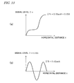
- FIG. 13 ( a ) shows how the signal ⁇ Tr changes with the horizontal distance X in a third exemplary embodiment and ( b ) shows how the signal ⁇ Tr ⁇ (1/2)X changes with the horizontal distance X in the third exemplary embodiment.
- FIG. 14 Illustrates the arrangement of an image capturing system according to Patent Document No. 1.
- FIG. 15 Illustrates the arrangement of an image capturing system according to Patent Document No. 2.
- FIG. 16 Illustrates the arrangement of an image capturing system according to Patent Document No. 4.
- FIG. 17 Illustrates the appearance of a light beam confining plate according to Patent Document No. 5.
- FIG. 18 Illustrates the appearance of a light beam confining plate according to Patent Document No. 6.
- a 3D image capture device as an embodiment of the present invention includes: a light transmitting section with a transmitting area, of which the spectral transmittance characteristic varies in a first direction; an image sensor which is arranged to receive light that has been transmitted through the light transmitting section and which outputs a photoelectrically converted signal representing the light received; an imaging section which produces an image on the image capturing plane of the image sensor; and an image processing section which extracts an edge of a subject in the first direction, which is included in an image that has been generated based on the photoelectrically converted signal supplied from the image sensor, and which estimates information about the depth of the subject based on lightness or hue pattern of a background in the vicinity of the edge extracted.
- the transmission wavelength range of the transmitting area changes into three or more different ones in the first direction.
- the transmitting area is designed so that when achromatic color light is transmitted through the transmitting area, the sum of transmitted light rays becomes the achromatic color light.
- the 3D image capture device of one of (1) to (3) includes a rotating and driving section which rotates the transmitting area on a plane that intersects with an optical axis at right angles, and the image processing section extracts the edge of the subject by comparing to each other a plurality of images that have been obtained in mutually different rotation states.
- the image processing section extracts the edge of the subject based on the difference between a first image obtained when the transmitting area was in a first state and a second image obtained when the transmitting area was in a second state, which is defined by rotating the transmitting area in the first state 180 degrees.
- the spectral transmittance characteristic of the transmitting area changes continuously and periodically in the first direction.
- the transmitting area has six areas which are arranged in the first direction and which transmit light rays falling within the wavelength ranges of the colors blue, cyan, green, yellow, red and magenta, respectively.
- the image processing section estimates the depth of the subject by reference to information that has been collected in advance to define a relation between the depth of the subject and a lightness or hue pattern in pixels surrounding the edge.
- the rest of the light transmitting section other than the transmitting area is transparent.
- the image processing section In one embodiment of the 3D image capture device of one of (1) to (9), the image processing section generates a depth image, of which each pixel value is represented by the level of the depth, by reference to information indicating the estimated depth.
- the image processing section generates a color image based on the photoelectrically converted signal supplied from the image sensor.
- a light transmitting section as an embodiment of the present invention may be used by the 3D image capture device of one of (1) to (11).
- An image processor as an embodiment of the present invention may be used by the 3D image capture device of one of (1) to (11).
- the image processor includes an image processing section which extracts an edge of a subject in the first direction, which is included in an image that has been generated based on the photoelectrically converted signal supplied from the image sensor, and which estimates information about the depth of the subject based on a lightness or hue pattern of a background in the vicinity of the edge extracted.
- An image processing program as an embodiment of the present invention may be used by the 3D image capture device of one of (1) to (11).
- the image processing program is defined so as to make a computer perform the steps of: extracting an edge of a subject in the first direction, which is included in an image that has been generated based on the photoelectrically converted signal supplied from the image sensor; and estimating information about the depth of the subject based on a lightness or hue pattern of a background in the vicinity of the edge extracted.
- FIG. 1 is a block diagram illustrating an overall configuration for an image capture device according to this embodiment.
- the image capture device of this embodiment is a digital electronic camera and includes an image capturing section 100 and a signal processing section 200 that receives a signal generated by the image capturing section 100 and outputs a signal representing an image (i.e., an image signal).
- the image capturing section 100 includes a color solid-state image sensor 2 a (which will be simply referred to herein as an “image sensor”) with a number of photosensitive cells (pixels) that are arranged on its image capturing plane, a light-transmitting plate (light-transmitting section) 2 , in which a striped color filter, of which the spectral transmittance characteristic varies in a particular direction, is arranged and which transmits incoming light, an optical lens 3 for producing an image on the image capturing plane of the color solid-state image sensor 2 a , and an infrared cut filter 4 .
- a color solid-state image sensor 2 a which will be simply referred to herein as an “image sensor”
- a light-transmitting plate (light-transmitting section) 2 in which a striped color filter, of which the spectral transmittance characteristic varies in a particular direction, is arranged and which transmits incoming light
- an optical lens 3 for producing an image on the image capturing plane of the
- the image capturing section 100 further includes a signal generating and receiving section 5 , which not only generates a fundamental signal to drive the color solid-state image sensor 2 a but also receives the output signal of the color solid-state image sensor 2 a and sends it to the signal processing section 200 , and a sensor driving section 6 for driving the color solid-state image sensor 2 a in accordance with the fundamental signal generated by the signal generating and receiving section 5 .
- the color solid-state image sensor 2 a is typically a CCD or CMOS sensor, which may be fabricated by known semiconductor device processing technologies.
- the signal generating and receiving section 5 and the sensor driving section 6 may be implemented as an LSI such as a CCD driver.
- the “spectral transmittance characteristic” refers herein to the wavelength dependence of a transmittance in the visible radiation wavelength range.
- the signal processing section 200 includes an image processing section 7 which generates a color image and subject's depth information by processing the signal supplied from the image capturing section 100 , a memory 30 for storing various kinds of data for use to generate the image signal, and an interface (I/F) section 8 for sending out the image signal and depth information thus generated to an external device.
- the image processing section 7 may be implemented appropriately as a combination of a hardware component such as a known digital signal processor (DSP) and a software program for use to perform image processing involving the image signal generation.
- DSP digital signal processor
- the image processing section 7 not only generates a color image but also extracts an edge from the image and calculates depth information based on color information in the vicinity of the edge.
- the image processing section 7 transforms the depth information into a luminance signal, thereby generating a monochrome image representing the distribution of depths.
- the memory 30 may be a DRAM, for example. And the memory 30 not only stores the signal supplied from the image capturing section 100 but also temporarily retains the image data that has been generated by the image processing section 7 or compressed image data. These image data are then output to either a storage medium or a display section (neither is shown) by way of the interface section 8 .
- the image capture device of this embodiment actually further includes an electronic shutter, a viewfinder, a power supply (or battery), a flashlight and other known components.
- an electronic shutter or a viewfinder
- a power supply or battery
- a flashlight or a flashlight
- FIG. 2 schematically illustrates the relative arrangement of the light-transmitting plate 1 , the lens 3 and the image sensor 2 a in the image capturing section 100 .
- the lens 3 may be a lens unit that is a group of lenses but is drawn in FIG. 2 as a single lens for the sake of simplicity.
- the light-transmitting plate includes a striped color filter (light transmitting area) 1 a , of which the spectral transmittance characteristic varies in the horizontal direction, and transmits the incoming light.
- the lens 3 is a known lens and condenses the light that has been transmitted through the light-transmitting plate 1 , thereby imaging the light on the image capturing plane 2 a of the image sensor 2 .
- the “horizontal direction” means the x direction shown in the drawings that are referred to, and is not necessarily the direction that is parallel to the surface of the ground.
- FIG. 3 is a front view of the light-transmitting plate 1 according to this embodiment.
- the light-transmitting plate 1 of this embodiment, as well as the lens 3 has a circular shape.
- the light-transmitting plate 1 has a striped color filter 1 a which runs through its middle but the rest 1 b of the plate 1 is transparent.
- This striped color filter 1 a is characterized in that its transmission wavelength range gradually changes in the order of the colors red (R), yellow (Ye), green (G), cyan (Cy), blue (B) and magenta (Mg) from the left to the right on the drawing and that the sum of all of these colors becomes the color white.
- the transmittances of the R, G and B portions of the filter are supposed to be substantially equal to each other and the transmittances of the Ye, Cy and Mg portions of the filter are supposed to be approximately twice as high as that of the R, G and B portions.
- FIG. 4 illustrates some of a plurality of photosensitive cells 5 which are arranged in columns and rows on the image capturing plane 2 b of the image sensor 2 a .
- Each of those photosensitive cells 50 is typically a photodiode, which performs photoelectric conversion and outputs an electrical signal representing the quantity of the light received (which will be referred to herein as a “photoelectrically converted signal” or a “pixel signal”).
- Color filters are arranged closer to the light source so as to face the respective photosensitive cells 50 . As shown in FIG.
- the color filters have a horizontal striped arrangement, each fundamental unit of which is comprised of three color filters that are arranged in three rows and one column, and red (R), green (G) and blue (B) elements are arranged on the first, second and third rows, respectively.
- the color filter of each of these elements may be made of a known pigment, for example.
- the color filters of the red, green and blue elements selectively transmit light rays falling within the red, green and blue wavelength ranges, respectively.
- the light that has entered this image capture device during an exposure process passes through the light-transmitting plate 1 , the lens 3 , and the infrared cut filter 4 , is imaged on the image capturing plane 2 b of the image sensor 2 a , and then is photoelectrically converted by each photosensitive cells 50 .
- the photoelectrically converted signal is output from each photosensitive cell 50 to the signal processing section 200 via the signal generating and receiving section 5 .
- the image processing section 7 colors the image and calculates depth information based on the signal supplied.
- the depth information is transformed into a luminance signal according to the level of its depth and is output as a monochrome image.
- FIG. 5 schematically illustrates a situation where images of a background 32 and a foreground subject 31 are captured through the light-transmitting plate 1 .
- the image sensor 2 a When their images are captured in the situation shown in FIG. 5 , the image sensor 2 a outputs a photoelectrically converted signal based on the light that has been reflected from the foreground subject 31 and the background 32 .
- the photoelectrically converted signal is then sent from the image sensor 2 a to the image processing section 7 via the signal generating and receiving section 5 .
- the image processing section 7 performs the following two kinds of processing on the photoelectrically converted signal supplied, and outputs two images as the results of those two kinds of processing. Specifically, predetermined coloration processing is carried out as the first processing, thereby generating a color image.
- an edge of the image is extracted, the depth is estimated based on the horizontal coloration in the vicinity of the edge, and a monochrome image, of which the image luminance value is represented by the level of the depth (which will be referred to herein as a “depth image”), is generated.
- a monochrome image of which the image luminance value is represented by the level of the depth (which will be referred to herein as a “depth image”), is generated.
- FIG. 6 is a flowchart showing the procedure of the image generation processing according to this embodiment.
- the image processing section 7 generates a color image based on the photoelectrically converted signal that has been generated by the image sensor 2 a .
- Step S 11 the image processing section 7 extracts a horizontal edge of the subject which is included in the color image generated.
- Step S 12 the image processing section 7 detects the color of the background in the vicinity of the edge.
- Step S 13 the image processing section 7 detects a hue pattern of pixels in the vicinity of the edge.
- Step S 14 the image processing section 7 calculates the subject's depth based on the hue pattern of pixels in the vicinity of the edge.
- the image processing section 7 generates a depth image based on the level of the depth calculated.
- these processing steps will be described in detail one by one.
- Step S 10 a color image is generated based on the output of the image sensor 2 a .
- the image sensor 2 a has a horizontal stripe arrangement of RGB. That is why RGB signals (i.e., color signals) can be obtained directly by using three pixels that are arranged in three rows and one column as a unit, and color image is generated based on these color signals.
- RGB signals i.e., color signals
- the horizontal stripe color arrangement shown in FIG. 4 is used according to this embodiment, a color image with high horizontal resolution can be generated.
- the striped color filter 1 a is arranged in this embodiment to run through the middle of the light-transmitting plate 1 , light is partially absorbed into the color filter 1 a and some quantity of the light is lost.
- the color scheme of the striped color filter 1 a includes not only primary colors (R, G, B) but also complementary colors (Ye, Cy, Mg) as well. That is why higher optical transmittance is achieved than in an arrangement that uses only primary color filters.
- the color scheme of the striped color filter 1 a includes not only primary colors (R, G, B) but also complementary colors (Ye, Cy, Mg) as well. That is why higher optical transmittance is achieved than in an arrangement that uses only primary color filters.
- the sum of the light rays that are transmitted through the striped color filter 1 a is white light, basically the subject image is not colored by the striped color filter 1 a .
- a color image of which the sensitivity and color properties have no problem at all, can be generated by setting the size of the striped color filter 1 a to be sufficiently small.
- the image processing section 7 extracts a horizontal edge of the image that has been obtained by capturing (i.e., the image captured).
- the edge of the image can be extracted by several methods, any of which may be adopted.
- the edge is supposed to be extracted based on the result of the color image generation processing described above. Specifically, first of all, color components are removed from the color image that has been obtained through the color image generation processing described above, thereby obtaining a monochrome image. Next, a signal difference is calculated between two horizontally adjacent pixels of the monochrome image. And if the differential value is equal to or greater than a preset level, then that part is regarded as the horizontal edge of the image. By performing such signal difference processing on the entire image, the image processing section 7 extracts horizontal edges.
- Step S 12 the color of the background in the vicinity of the edge extracted is detected.
- the color is detected from an area that is located on the left-hand side of the edge (e.g., corresponding to the left image capturing area 33 shown in FIG. 5 ) in the left half of the image and from an area that is located on the right-hand side of the edge (e.g., corresponding to the right image capturing area 34 shown in FIG. 5 ) in the right half of the image.
- the specific area widths i.e., the numbers of horizontal pixels
- the image areas corresponding to the left and right image capturing areas 34 and 34 are affected by the striped color filter 1 a and their colors change continuously in the horizontal direction. For instance, a light ray that has been incident on the image sensor 2 a from the leftmost portion of the right image capturing area 34 shown in FIG. 5 transmits only through the right end (Mg area) of the striped color filter 1 a , and therefore, pixels corresponding to that portion are colored Mg.
- FIG. 7 schematically illustrates the signal levels of six horizontal pixels on the image that correspond to the right image capturing area 34 .
- the signal levels increase from a pixel corresponding to the leftmost portion of the right image capturing area 34 toward a pixel corresponding to the rightmost portion thereof.
- signals representing seven pixels that are arranged horizontally are identified by S(i), S(i+1), S(i+2) . . . and S(i+6) and an edge is supposed to be present in the boundary between S(i) and S(i+1).
- a signal indicating the intensity of each color component included in one of these signals is represented by the sign indicating that color component (Mg, B, Cy, G, Ye, R)
- a pixel signal S(i+1) corresponding to the leftmost portion of the right image capturing area 34 is represented by Mg+k(1) (R+G+B).
- a pixel signal S(i+6) corresponding to the rightmost portion of the right image capturing area 34 is represented by (Mg+B+Cy+G+Ye+R)+k(6)(R+G+B).
- S(i+2) is represented by (Mg+B)+k(2) (R+G+B)
- S(i+3) is represented by (Mg+B+Cy)+k(3) (R+G+B)
- S(i+4) is represented by (Mg+B+Cy+G)+k(4) (R+G+B)
- S(i+5) is represented by (Mg+B+Cy+G+Ye)+k(5) (R+G+B).
- the pixel unit is supposed to be comprised of the three pixels that are arranged in three rows and one column shown in FIG. 4 and those three pixels are supposed to form a single pixel.
- k(j) is a known number determined by the lens shape
- this RGB ratio can be obtained.
- the RGB ratio varies according to the color of the background in the vicinity of an edge, the color of the background can be determined by obtaining the RGB ratio.
- the background color can be determined to be Cy.
- a database that associates an RGB ratio with its corresponding background color is collected in advance and stored in the memory 30 .
- the image processing section 7 detects the color of the background area in the vicinity of an edge based on the RGB ratio of pixels in the vicinity of the edge on the image.
- Step S 13 the hue pattern in an area surrounding the edge is detected. Specifically, signals representing the color components that have been detected in Step S 12 are removed from respective pixel signals in the edge surrounding area and then the difference is calculated between the pixels, thereby calculating a color component. For instance, since the color of the right image capturing area 34 is white in the example shown in FIG. 7 , a white component k(j)(R+G+B) is removed from the respective pixel signals S(i+1), S(i+2) and so on.
- S ( i+ 2) Mg+B (2)
- S ( i+ 3) Mg+B ⁇ Cy (3)
- S ( i+ 4) Mg+B ⁇ Cy+G (4)
- S ( i+ 5) Mg+B ⁇ Cy+G+Ye (5)
- S ( i+ 6) Mg+B ⁇ Cy+G+Ye+R (6)
- signals Mg through R representing the colors of the striped color filter 1 a when the light source is white can be calculated. It can be said that this is equivalent to calculating the colors to be transmitted through the striped color filter using the color of the edge surrounding areas such as the right and left image areas 34 and 33 as the color of a light source.
- Step S 14 a property of the color pattern surrounding the edge is examined and the depth corresponding to that property is calculated.
- the depth refers herein to the distance from the subject 31 to the background 32 shown in FIG. 5 . If the depth/distance is short, then the hue pattern is limited. Conversely, if the depth/distance is long, then the hue pattern range expands. That is to say, there is a correlation between the subject's ( 31 ) depth information and the hue pattern in the vicinity of the edge. In this embodiment, data representing that correlation is provided in advance and stored in the memory 30 . By reference to that correlation data, the image processing section 7 calculates the depth based on the hue pattern at the edge.
- the hue pattern in the right image capturing area 34 is represented by Equation (1) and Equations (7) through (11) (i.e., in a situation where six colors can be obtained from six pixels) the distance from the foreground subject 31 to the background 32 becomes a half, then three colors can be obtained from three pixels as shown in FIG. 8 .
- the image processing section 7 of this embodiment obtains depth information based on that correlation. Nevertheless, the depth information is not absolute distance information as in the example described above but just a piece of relative information.
- Step S 15 the depth information that has been obtained in Step S 14 is transformed into brightness information (i.e., a monochrome image).
- the image processing section 7 scans the captured image horizontally, and calculates the depth every time an edge is detected. Then, pieces of depth information calculated are accumulated and added together, thereby calculating a maximum depth value.
- the maximum depth value as a maximum brightness value, the brightness of each pixel is determined. For example, in transforming the depth information into an eight-bit monochrome image, the information can be transformed into an image with a maximum luminance value of 255.
- the image capture device of this embodiment can obtain not only a color image with only a little loss of light but also the subject's depth image.
- the image capture device of this embodiment by extracting an edge from the color image obtained and by examining the hue of the colors in the area surrounding that edge, a relative depth between the subjects can be calculated, which is very advantageous.
- information about, the relative depth between the subjects can be obtained, information about the subject's depth with respect to the image capture device's position can also be obtained by making computations based on that relative depth information.
- each filter portion of the striped color filter 1 a is supposed to be configured to transmit only a light ray falling within its associated particular wavelength range but not to transmit any other light ray.
- the R, G and B filter portions are supposed to have substantially the same transmittance and the transmittance of the Ye, Cy and Mg filter portions is supposed to be approximately twice as high as that of the R, G and B filter portions.
- the striped color filter 1 a does not have to satisfy these conditions exactly. Naturally, these conditions are ideally satisfied but even if the characteristic of the striped color filter 1 a varied from the ideal one, there would be no problem if the signal processing described above is corrected so as to compensate for that variation.
- the color scheme of the striped color filter 1 a of the light-transmitting plate 1 is supposed to be comprised of red (R), yellow (Ye), green (G), cyan (Cy), blue (B) and magenta (Mg).
- R red
- Ye yellow
- G green
- Cy cyan
- B blue
- Mg magenta
- the number of different color schemes of the striped color filter 1 a does not have to be seven. Nevertheless, in order to increase the accuracy of calculating the depth, it is recommended that there be at least three different color schemes.
- the sum of all colors of the striped color filter 1 a suitably becomes the color white as in the embodiment described above.
- the sum does not have to be exactly the color white.
- a striped color filter 1 a of which the sum of all colors is close to the color white, is used, the image obtained can be used as a color image with no problem at all and yet the depth information can also be calculated.
- the basic color arrangement of the color image sensor 2 a is supposed to be an RGB horizontal stripe arrangement.
- RGB horizontal stripe arrangement any other basic color arrangement consisting of three or more colors may also be used.
- a Bayer arrangement consisting of red, blue and two green elements may also be used with no problem at all.
- the condenser lens 3 and the light-transmitting plate 1 are supposed to be circular, the effects will not be affected at all even if the condenser lens 3 and the light-transmitting plate 1 have a quadrangle or any other arbitrary shape.
- the color filter 1 a of the light-transmitting plate 1 is supposed to have a striped shape, this is only an example and the color filter may also cover the entire surface of the light-transmitting plate 1 .
- a filter of which the hue (i.e., transmission wavelength range) changes in the rotating direction and the color depth (i.e., transmittance) changes in the radial direction as in a Munsell color ring, is used, then depth can be calculated not just in the horizontal direction but also in every other direction as well.
- a filter of which the transmission wavelength range or transmittance changes concentrically, may also be used.
- the transmittance characteristic is suitably designed so that the sum of the transmitted light rays becomes close to white light.
- the arrangement of the respective members shown in FIG. 2 is only an example. And the present invention is in no way limited to that specific example.
- the lens 3 may be arranged more distant from the image sensor 2 a than the light-transmitting plate 1 is. Still alternatively, the lens 3 and the light-transmitting plate 1 may also be implemented as a single optical element.
- the image processing section 7 generates a color image and a depth image at the same time.
- the image processing section 7 may generate only a depth image without generating any color image.
- the image processing section may also be configured to generate only depth information, not any depth image, by performing the processing described above.
- the image processing of this embodiment may also be carried out by another device that is provided independently of that image capture device. For example, even if a signal that has been obtained by an image capture device including the image capturing section 100 of this embodiment is loaded into another device (image processor) to get a program defining the signal arithmetic processing described above executed by a computer built in that image processor, the effects of the embodiment described above can also be achieved.
- a rotating mechanism is attached to the light-transmitting plate 1 and rotates the light-transmitting plate 1 on a plane that intersects with the optical axis at right angles, thereby getting images captured twice in a row.
- the configuration of this second embodiment is the same as that of the first embodiment, and their common features will not be described all over again to avoid redundancies.
- FIG. 9 is a block diagram illustrating an overall configuration for an image capture device according to this embodiment.
- the image capture device of this embodiment includes a rotating and driving section 40 as a rotating mechanism.
- the rotating and driving section 40 has a motor that rotates the light-transmitting plate 1 and turns the light-transmitting plate 1 in accordance with an instruction given by the sensor driving section 6 .
- the light-transmitting plate 1 may be rotated by putting a belt on the light-transmitting plate 1 and by running the belt with a motor.
- the image capture device captures an image once with the striped color filter 1 a of the light-transmitting plate 1 kept parallel to the horizontal direction (see portion (a)), turns the light-transmitting plate 1 180 degrees, and captures an image once again (see portion (b)).
- These two images captured are subjected to differential processing and different portions as image data are extracted based on the result of the differential processing. In this manner, areas on the image corresponding to the left and right image capturing areas 33 and 34 can be located
- the left and right image capturing areas 33 and 34 cannot be located exactly according to the first embodiment described above, those areas can be located accurately according to this embodiment.
- the reason is that the pixels that define the left and right image capturing areas 33 and 34 come to have different signal levels as the color scheme of the striped color filter 1 a changes every time an image is captured. That is why based on the difference between these two images, the left and right image capturing areas 33 and 34 can be located accurately.
- the same processing is carried out as in the first embodiment described above. According to this embodiment, since the left and right image capturing areas 33 and 34 can be located exactly, the depth can be calculated more accurately.
- the left and right image capturing areas 33 and 34 can be located accurately based on the difference between the two images captured. Consequently, the depth can be calculated even more accurately.
- images are supposed to be captured twice according to this embodiment by getting the light-transmitting plate 1 rotated 180 degrees by the rotating and driving section 40 , the angle of rotation and the number of times of capturing images may be changed.
- two pairs of multi-viewpoint images which are located at the upper, lower, right and left corners, respectively, may also be generated by performing image capturing operations four times with the light-transmitting plate 1 rotated 90 degrees each time.
- the striped color filter 1 a of the light-transmitting plate 1 is arranged as in the first embodiment described above but its spectral transmittance characteristic changes differently from in the first embodiment.
- the striped color filter 1 a of this embodiment has the color grey (i.e., has no wavelength selectivity) and its transmittance changes periodically in the horizontal direction (i.e., in the x direction). Since the color filter 1 a is a grey filter, the depth is calculated according to this embodiment based on the luminance signal of a color image, not RGB pixel signals.
- the following description of the third embodiment will be focused on only those differences from the first embodiment and their common features will not be described all over again to avoid redundancies.
- FIG. 11 is a front view of the light-transmitting plate 1 according to this embodiment.
- the striped color filter 1 a does not have wavelength selectivity but its transmittance changes just like a cos function and becomes outstandingly high at two points and very low at two points.
- FIG. 12 is a graph showing how its transmittance changes.
- the luminance values of image areas corresponding to the left and right image capturing areas 33 and 34 are obtained by finding an integral of the transmittance of the striped color filter 1 a horizontally.
- the optical transmittance Tr is a periodic function represented by Equation (12)
- FIG. 13( a ) is a graph showing the integral value E Tr given by Equation (13).
- the periodic function of the first term before and after the integral operation is characterized by its waveform that does not change because the cos function just turns into a sin function.
- the image processing section 7 of this embodiment removes a signal corresponding to the linear function term of Equation (13) from pixel signals corresponding to the left and right image capturing areas 33 and 34 and then analyzes the waveforms of signals of multiple pixels that are arranged horizontally.
- FIG. 13( b ) is a graph showing a function that is obtained by removing a linear function term from Tr represented by Equation (13).
- the image processing section 7 detects a similar waveform to that of the periodic function shown in FIG.
- the image processing section 7 obtains the depth based on the waveform of the periodic function that is based on the image data.
- a light-transmitting plate 1 of which the striped color filter 1 a has the color grey and of which the transmittance changes periodically in the horizontal direction, is used.
- the waveform of a periodic function appears in the luminance values of image areas corresponding to the left and right image capturing areas 33 and 34 and the depth can be calculated based on that waveform. Consequently, according to this embodiment, information about the depth of the subject can be estimated based on a lightness pattern of the background in the vicinity of an edge.
- the striped color filter 1 a of the light-transmitting plate is supposed to have the color grey.
- the striped color filter 1 a may have any other color as long as its transmittance changed periodically.
- the striped color filter 1 a may also have wavelength selectivity. Even if the spectral transmittance characteristic pattern of the striped color filter 1 a is different from what has already been described, the depth information can also be obtained by performing signal processing according to the pattern of its spectral transmittance characteristic.
- the image sensor 2 a does not have to be a color image sensor but may also be a monochrome image sensor as well. Furthermore, the edge may also be extracted according to this embodiment by rotating the light-transmitting plate 1 as in the second embodiment described above.
- a 3D image capture device can be used effectively in any camera that ever uses a solid-state image sensor.
- Examples of those cameras include consumer electronic cameras such as digital cameras and digital camcorders and solid-state surveillance cameras for industrial use.
Abstract
Description
- Patent Document No. 1: Japanese Laid-Open Patent Publication No. 62-291292
- Patent Document No. 2: Japanese Laid-Open Patent Publication No. 62-217790
- Patent Document No. 3: Japanese Laid-Open Patent Publication No. 2001-016611
- Patent Document No. 4: Japanese Laid-Open Patent Publication No. 2-171737
- Patent Document No. 5: Japanese Laid-Open Patent Publication No. 2002-344999
- Patent Document No. 6: Japanese Laid-Open Patent Publication No. 2009-276294
- Patent Document No. 7: Japanese Laid-Open Patent Publication No. 2010-38788
- Patent Document No. 8: Japanese Laid-Open Patent Publication No. 2010-79298
- Patent Document No. 9: Japanese Laid-Open Patent Publication No. 2003-134533
- Non-Patent Document No. 1: Yuta MORIUE, Takeshi TAKAKI, and Idaku ISHII, A Real-time Monocular Stereo System Using a Viewpoint Switching Iris, Transactions of the 27th Annual Conference of the Robotics Society of Japan, 3R2-06, 2009.
S(i+1)=Mg (1)
S(i+2)=Mg+B (2)
S(i+3)=Mg+B±Cy (3)
S(i+4)=Mg+B±Cy+G (4)
S(i+5)=Mg+B±Cy+G+Ye (5)
S(i+6)=Mg+B±Cy+G+Ye+R (6)
D12=S(i+2)−S(i+1)=B (7)
D23=S(i+3)−S(i+2)=Cy (8)
D34=S(i+4)−S(i+3)=G (9)
D45=S(i+5)−S(i+4)=Ye (10)
D56=S(i+6)−S(i+5)=R (11)
Tr==(½)cos X+½ (12)
ΣTr=(1/2)sin X+(1/2)X (13)
- 1 light-transmitting plate
- 1 a striped color filter
- 1 b transparent area
- 2 solid-state image sensor
- 2 a color solid-state image sensor
- 2 b image capturing plane
- 3 optical lens
- 4 infrared cut filter
- 5 signal generating and receiving section
- 6 sensor driving section
- 7 image processing section
- 8 image interface section
- 9 image capture device
- 10 pixel
- 11 0-degree-polarization polarizer
- 12 90-degree-polarization polarizer
- 13 reflective mirror
- 14 half mirror
- 15 circular polarization filter
- 16 driver that rotates polarization filter
- 17, 18 polarization filter
- 19 lens diaphragm
- 20, 22, 23 light beam confining plate
- 20 a color filter that transmits red-based ray
- 20 b color filter that transmits blue-based ray
- 21 photosensitive film
- 22R, 23R R ray transmitting area of light beam confining plate
- 22G, 23G G ray transmitting area of light beam confining plate
- 22B, 23B B ray transmitting area of light beam confining plate
- 30 memory
- 31 foreground subject
- 32 background
- 33 left image capturing area
- 34 right image capturing area
- 40 rotating and driving section
- 50 pixel
Claims (13)
Applications Claiming Priority (3)
| Application Number | Priority Date | Filing Date | Title |
|---|---|---|---|
| JP2011-096333 | 2011-04-22 | ||
| JP2011096333 | 2011-04-22 | ||
| PCT/JP2012/002517 WO2012144162A1 (en) | 2011-04-22 | 2012-04-11 | Three-dimensional image pickup apparatus, light-transparent unit, image processing apparatus, and program |
Publications (2)
| Publication Number | Publication Date |
|---|---|
| US20130107009A1 US20130107009A1 (en) | 2013-05-02 |
| US9544570B2 true US9544570B2 (en) | 2017-01-10 |
Family
ID=47041296
Family Applications (1)
| Application Number | Title | Priority Date | Filing Date |
|---|---|---|---|
| US13/807,059 Active 2033-07-15 US9544570B2 (en) | 2011-04-22 | 2012-04-11 | Three-dimensional image pickup apparatus, light-transparent unit, image processing apparatus, and program |
Country Status (4)
| Country | Link |
|---|---|
| US (1) | US9544570B2 (en) |
| JP (1) | JP5927570B2 (en) |
| CN (1) | CN102918355B (en) |
| WO (1) | WO2012144162A1 (en) |
Families Citing this family (7)
| Publication number | Priority date | Publication date | Assignee | Title |
|---|---|---|---|---|
| JP6173065B2 (en) * | 2013-06-21 | 2017-08-02 | オリンパス株式会社 | Imaging apparatus, image processing apparatus, imaging method, and image processing method |
| KR102112298B1 (en) * | 2013-09-30 | 2020-05-18 | 삼성전자주식회사 | Method and apparatus for generating color image and depth image |
| US20150229910A1 (en) * | 2014-02-07 | 2015-08-13 | National University Of Singapore | Method and apparatus for stereoscopic imaging |
| US9491442B2 (en) | 2014-04-28 | 2016-11-08 | Samsung Electronics Co., Ltd. | Image processing device and mobile computing device having the same |
| US10416511B2 (en) * | 2016-08-31 | 2019-09-17 | Panasonic Liquid Crystal Display Co., Ltd. | Liquid crystal display device |
| WO2022244176A1 (en) * | 2021-05-20 | 2022-11-24 | 日本電気株式会社 | Out-of-stock detection device, out-of-stock detection method, and program |
| CN113867076B (en) * | 2021-11-08 | 2023-04-28 | Oppo广东移动通信有限公司 | Apodization filter, preparation method thereof and related products |
Citations (36)
| Publication number | Priority date | Publication date | Assignee | Title |
|---|---|---|---|---|
| JPS62217790A (en) | 1986-03-19 | 1987-09-25 | Nippon Hoso Kyokai <Nhk> | Stereoscopic image system |
| JPS62291292A (en) | 1986-06-11 | 1987-12-18 | Sharp Corp | Image pickup device |
| JPH02171737A (en) | 1988-12-26 | 1990-07-03 | Minolta Camera Co Ltd | Photographing lens for stereo camera |
| JPH02171740A (en) | 1988-12-26 | 1990-07-03 | Minolta Camera Co Ltd | Camera for stereo photograph |
| JPH1198418A (en) | 1997-09-24 | 1999-04-09 | Toyota Central Res & Dev Lab Inc | Image pickup device |
| CN1243263A (en) | 1998-07-09 | 2000-02-02 | 松下电器产业株式会社 | Stereopicture obtaining device |
| JP2001016611A (en) | 1999-06-29 | 2001-01-19 | Fuji Photo Film Co Ltd | Parallax image pickup device and camera |
| JP2001074432A (en) | 1999-09-08 | 2001-03-23 | Fuji Xerox Co Ltd | Image pickup device |
| US20020171740A1 (en) | 2001-05-21 | 2002-11-21 | Asahi Kogaku Kogyo Kabushiki Kaisha | Stereo-image capturing device |
| JP2003134533A (en) | 2001-10-30 | 2003-05-09 | Pentax Corp | Stereo image pickup device |
| CN1502056A (en) | 2001-04-14 | 2004-06-02 | Apparatus for recording three dimensional video and movie camera | |
| US6807295B1 (en) | 1999-06-29 | 2004-10-19 | Fuji Photo Film Co., Ltd. | Stereoscopic imaging apparatus and method |
| US20050002559A1 (en) * | 2003-06-30 | 2005-01-06 | Tomoya Terauchi | Depth measuring method and depth measuring apparatus |
| CN1830217A (en) | 2003-08-05 | 2006-09-06 | 皇家飞利浦电子股份有限公司 | Multi-view image generation |
| JP2008152244A (en) | 2006-11-22 | 2008-07-03 | Canon Inc | Display device |
| US20080174849A1 (en) | 2006-11-22 | 2008-07-24 | Canon Kabushiki Kaisha | Display apparatus |
| US20080260288A1 (en) * | 2004-02-03 | 2008-10-23 | Koninklijke Philips Electronic, N.V. | Creating a Depth Map |
| US20090041449A1 (en) * | 2005-12-12 | 2009-02-12 | Topins Co., Ltd. | The testing matter photographing apparatus attached three dimensional image photographing device |
| US20090103782A1 (en) * | 2007-10-23 | 2009-04-23 | Samsung Electronics Co., Ltd. | Method and apparatus for obtaining depth information |
| US20090284627A1 (en) * | 2008-05-16 | 2009-11-19 | Kaibushiki Kaisha Toshiba | Image processing Method |
| JP2010038788A (en) | 2008-08-06 | 2010-02-18 | National Institute Of Advanced Industrial & Technology | Height measuring method and height measuring instrument |
| US20100066854A1 (en) | 2008-09-12 | 2010-03-18 | Sharp Kabushiki Kaisha | Camera and imaging system |
| US20100182410A1 (en) * | 2007-07-03 | 2010-07-22 | Koninklijke Philips Electronics N.V. | Computing a depth map |
| US20110134109A1 (en) * | 2009-12-09 | 2011-06-09 | StereoD LLC | Auto-stereoscopic interpolation |
| US20110135194A1 (en) * | 2009-12-09 | 2011-06-09 | StereoD, LLC | Pulling keys from color segmented images |
| US20110234756A1 (en) * | 2010-03-26 | 2011-09-29 | Microsoft Corporation | De-aliasing depth images |
| US20110249886A1 (en) * | 2010-04-12 | 2011-10-13 | Samsung Electronics Co., Ltd. | Image converting device and three-dimensional image display device including the same |
| WO2011142062A1 (en) | 2010-05-11 | 2011-11-17 | パナソニック株式会社 | Three-dimensional imaging device |
| WO2011151948A1 (en) | 2010-06-02 | 2011-12-08 | パナソニック株式会社 | Three-dimensional image pickup device |
| US20120002862A1 (en) * | 2010-06-30 | 2012-01-05 | Takeshi Mita | Apparatus and method for generating depth signal |
| US20130060146A1 (en) * | 2010-04-28 | 2013-03-07 | Ryerson University | System and methods for intraoperative guidance feedback |
| US20130317861A1 (en) * | 2012-05-24 | 2013-11-28 | Nathan Lee Tofte | System And Method For Real-Time Accident Documentation And Claim Submission |
| US20140049535A1 (en) * | 2012-08-14 | 2014-02-20 | Hong Kong Applied Science and Technology Research Institute Company Limited | Method and System for Rapid Three-Dimensional Shape Measurement |
| US20140169701A1 (en) * | 2012-12-19 | 2014-06-19 | Hong Kong Applied Science and Technology Research Institute Co., Ltd. | Boundary-based high resolution depth mapping |
| US20150029312A1 (en) * | 2012-02-21 | 2015-01-29 | Chung-Ang University Industry-Academy Cooperation Foundation | Apparatus and method for detecting object automatically and estimating depth information of image captured by imaging device having multiple color-filter aperture |
| US9153032B2 (en) * | 2008-09-25 | 2015-10-06 | Samsung Electronics Co., Ltd. | Conversion method and apparatus with depth map generation |
Family Cites Families (3)
| Publication number | Priority date | Publication date | Assignee | Title |
|---|---|---|---|---|
| JPS62292292A (en) * | 1986-06-12 | 1987-12-18 | Yamazaki Mazak Corp | Laser beam machine |
| JP5406151B2 (en) * | 2010-09-24 | 2014-02-05 | パナソニック株式会社 | 3D imaging device |
| JP5406163B2 (en) * | 2010-10-21 | 2014-02-05 | パナソニック株式会社 | 3D imaging apparatus and image processing apparatus |
-
2012
- 2012-04-11 US US13/807,059 patent/US9544570B2/en active Active
- 2012-04-11 WO PCT/JP2012/002517 patent/WO2012144162A1/en active Application Filing
- 2012-04-11 CN CN201280001375.9A patent/CN102918355B/en active Active
- 2012-04-11 JP JP2013510864A patent/JP5927570B2/en active Active
Patent Citations (44)
| Publication number | Priority date | Publication date | Assignee | Title |
|---|---|---|---|---|
| JPS62217790A (en) | 1986-03-19 | 1987-09-25 | Nippon Hoso Kyokai <Nhk> | Stereoscopic image system |
| JPS62291292A (en) | 1986-06-11 | 1987-12-18 | Sharp Corp | Image pickup device |
| JPH02171737A (en) | 1988-12-26 | 1990-07-03 | Minolta Camera Co Ltd | Photographing lens for stereo camera |
| JPH02171740A (en) | 1988-12-26 | 1990-07-03 | Minolta Camera Co Ltd | Camera for stereo photograph |
| JPH1198418A (en) | 1997-09-24 | 1999-04-09 | Toyota Central Res & Dev Lab Inc | Image pickup device |
| CN1243263A (en) | 1998-07-09 | 2000-02-02 | 松下电器产业株式会社 | Stereopicture obtaining device |
| US6603876B1 (en) * | 1998-07-09 | 2003-08-05 | Matsushita Electric Industrial Co., Ltd. | Stereoscopic picture obtaining device |
| JP2001016611A (en) | 1999-06-29 | 2001-01-19 | Fuji Photo Film Co Ltd | Parallax image pickup device and camera |
| US6807295B1 (en) | 1999-06-29 | 2004-10-19 | Fuji Photo Film Co., Ltd. | Stereoscopic imaging apparatus and method |
| JP2001074432A (en) | 1999-09-08 | 2001-03-23 | Fuji Xerox Co Ltd | Image pickup device |
| CN1502056A (en) | 2001-04-14 | 2004-06-02 | Apparatus for recording three dimensional video and movie camera | |
| US20040165062A1 (en) * | 2001-04-14 | 2004-08-26 | Seung-Yeon Kang | Apparatus for recording three dimensional video and movie camera |
| US20020171740A1 (en) | 2001-05-21 | 2002-11-21 | Asahi Kogaku Kogyo Kabushiki Kaisha | Stereo-image capturing device |
| JP2002344999A (en) | 2001-05-21 | 2002-11-29 | Asahi Optical Co Ltd | Stereoscopic image pickup device |
| JP2003134533A (en) | 2001-10-30 | 2003-05-09 | Pentax Corp | Stereo image pickup device |
| US20050002559A1 (en) * | 2003-06-30 | 2005-01-06 | Tomoya Terauchi | Depth measuring method and depth measuring apparatus |
| CN1830217A (en) | 2003-08-05 | 2006-09-06 | 皇家飞利浦电子股份有限公司 | Multi-view image generation |
| US20060232666A1 (en) * | 2003-08-05 | 2006-10-19 | Koninklijke Philips Electronics N.V. | Multi-view image generation |
| US20080260288A1 (en) * | 2004-02-03 | 2008-10-23 | Koninklijke Philips Electronic, N.V. | Creating a Depth Map |
| US20090041449A1 (en) * | 2005-12-12 | 2009-02-12 | Topins Co., Ltd. | The testing matter photographing apparatus attached three dimensional image photographing device |
| JP2008152244A (en) | 2006-11-22 | 2008-07-03 | Canon Inc | Display device |
| US20080174849A1 (en) | 2006-11-22 | 2008-07-24 | Canon Kabushiki Kaisha | Display apparatus |
| US20100182410A1 (en) * | 2007-07-03 | 2010-07-22 | Koninklijke Philips Electronics N.V. | Computing a depth map |
| US20090103782A1 (en) * | 2007-10-23 | 2009-04-23 | Samsung Electronics Co., Ltd. | Method and apparatus for obtaining depth information |
| JP2009276294A (en) | 2008-05-16 | 2009-11-26 | Toshiba Corp | Image processing method |
| US20090284627A1 (en) * | 2008-05-16 | 2009-11-19 | Kaibushiki Kaisha Toshiba | Image processing Method |
| JP2010038788A (en) | 2008-08-06 | 2010-02-18 | National Institute Of Advanced Industrial & Technology | Height measuring method and height measuring instrument |
| US20100066854A1 (en) | 2008-09-12 | 2010-03-18 | Sharp Kabushiki Kaisha | Camera and imaging system |
| JP2010079298A (en) | 2008-09-12 | 2010-04-08 | Sharp Corp | Camera and imaging system |
| US9153032B2 (en) * | 2008-09-25 | 2015-10-06 | Samsung Electronics Co., Ltd. | Conversion method and apparatus with depth map generation |
| US20110135194A1 (en) * | 2009-12-09 | 2011-06-09 | StereoD, LLC | Pulling keys from color segmented images |
| US20110134109A1 (en) * | 2009-12-09 | 2011-06-09 | StereoD LLC | Auto-stereoscopic interpolation |
| US20110234756A1 (en) * | 2010-03-26 | 2011-09-29 | Microsoft Corporation | De-aliasing depth images |
| US20110249886A1 (en) * | 2010-04-12 | 2011-10-13 | Samsung Electronics Co., Ltd. | Image converting device and three-dimensional image display device including the same |
| US20130060146A1 (en) * | 2010-04-28 | 2013-03-07 | Ryerson University | System and methods for intraoperative guidance feedback |
| WO2011142062A1 (en) | 2010-05-11 | 2011-11-17 | パナソニック株式会社 | Three-dimensional imaging device |
| US20120105598A1 (en) | 2010-05-11 | 2012-05-03 | Panasonic Corporation | Three-dimensional imaging device |
| WO2011151948A1 (en) | 2010-06-02 | 2011-12-08 | パナソニック株式会社 | Three-dimensional image pickup device |
| US20120133743A1 (en) | 2010-06-02 | 2012-05-31 | Panasonic Corporation | Three-dimensional image pickup device |
| US20120002862A1 (en) * | 2010-06-30 | 2012-01-05 | Takeshi Mita | Apparatus and method for generating depth signal |
| US20150029312A1 (en) * | 2012-02-21 | 2015-01-29 | Chung-Ang University Industry-Academy Cooperation Foundation | Apparatus and method for detecting object automatically and estimating depth information of image captured by imaging device having multiple color-filter aperture |
| US20130317861A1 (en) * | 2012-05-24 | 2013-11-28 | Nathan Lee Tofte | System And Method For Real-Time Accident Documentation And Claim Submission |
| US20140049535A1 (en) * | 2012-08-14 | 2014-02-20 | Hong Kong Applied Science and Technology Research Institute Company Limited | Method and System for Rapid Three-Dimensional Shape Measurement |
| US20140169701A1 (en) * | 2012-12-19 | 2014-06-19 | Hong Kong Applied Science and Technology Research Institute Co., Ltd. | Boundary-based high resolution depth mapping |
Non-Patent Citations (4)
| Title |
|---|
| Chinese Search Report and English translation thereof for corresponding Chinese Application No. 201280001375.9 dated May 7, 2015. |
| Form PCT/ISA/237 and partial English translation for corresponding International Application No. PCT/JP2012/002517 dated May 22, 2012. |
| International Search Report for corresponding International Application No. PCT/JP2012/002517 mailed May 22, 2012. |
| Yuta Moriue et al., "A Real-time Monocular Stereo System Using a Viewpoint Switching Iris", Transactions of the 27th Annual Conference of the Robotics Society of Japan, 3R2-06, 2009 and concise explanation. |
Also Published As
| Publication number | Publication date |
|---|---|
| JP5927570B2 (en) | 2016-06-01 |
| US20130107009A1 (en) | 2013-05-02 |
| CN102918355B (en) | 2017-05-31 |
| JPWO2012144162A1 (en) | 2014-07-28 |
| CN102918355A (en) | 2013-02-06 |
| WO2012144162A1 (en) | 2012-10-26 |
Similar Documents
| Publication | Publication Date | Title |
|---|---|---|
| US9798155B2 (en) | Image processing apparatus, image processing method, and program for generating a three dimensional image to be stereoscopically viewed | |
| US9036004B2 (en) | Three-dimensional image capture device | |
| US9544570B2 (en) | Three-dimensional image pickup apparatus, light-transparent unit, image processing apparatus, and program | |
| US9848118B2 (en) | Phase detection autofocus using opposing filter masks | |
| US9429834B2 (en) | Three-dimensional imaging device | |
| JP5923754B2 (en) | 3D imaging device | |
| WO2011151948A1 (en) | Three-dimensional image pickup device | |
| JP5853202B2 (en) | Imaging device | |
| US9628776B2 (en) | Three-dimensional imaging device, image processing device, image processing method, and image processing program | |
| US9179127B2 (en) | Three-dimensional imaging device, imaging element, light transmissive portion, and image processing device | |
| JP6034197B2 (en) | Image processing apparatus, three-dimensional imaging apparatus, image processing method, and image processing program | |
| US9086620B2 (en) | Three-dimensional imaging device and optical transmission plate | |
| US20130120540A1 (en) | Three-dimensional imaging device, image processing device, image processing method, and program |
Legal Events
| Date | Code | Title | Description |
|---|---|---|---|
| AS | Assignment |
Owner name: PANASONIC CORPORATION, JAPAN Free format text: ASSIGNMENT OF ASSIGNORS INTEREST;ASSIGNORS:HIRAMOTO, MASAO;ISHII, YASUNORI;SIGNING DATES FROM 20121218 TO 20121219;REEL/FRAME:030064/0721 |
|
| AS | Assignment |
Owner name: PANASONIC INTELLECTUAL PROPERTY MANAGEMENT CO., LTD., JAPAN Free format text: ASSIGNMENT OF ASSIGNORS INTEREST;ASSIGNOR:PANASONIC CORPORATION;REEL/FRAME:034194/0143 Effective date: 20141110 Owner name: PANASONIC INTELLECTUAL PROPERTY MANAGEMENT CO., LT Free format text: ASSIGNMENT OF ASSIGNORS INTEREST;ASSIGNOR:PANASONIC CORPORATION;REEL/FRAME:034194/0143 Effective date: 20141110 |
|
| STCF | Information on status: patent grant |
Free format text: PATENTED CASE |
|
| MAFP | Maintenance fee payment |
Free format text: PAYMENT OF MAINTENANCE FEE, 4TH YEAR, LARGE ENTITY (ORIGINAL EVENT CODE: M1551); ENTITY STATUS OF PATENT OWNER: LARGE ENTITY Year of fee payment: 4 |
|
| AS | Assignment |
Owner name: PANASONIC INTELLECTUAL PROPERTY MANAGEMENT CO., LTD., JAPAN Free format text: CORRECTIVE ASSIGNMENT TO CORRECT THE ERRONEOUSLY FILED APPLICATION NUMBERS 13/384239, 13/498734, 14/116681 AND 14/301144 PREVIOUSLY RECORDED ON REEL 034194 FRAME 0143. ASSIGNOR(S) HEREBY CONFIRMS THE ASSIGNMENT;ASSIGNOR:PANASONIC CORPORATION;REEL/FRAME:056788/0362 Effective date: 20141110 |