US9541258B2 - Lens for wide lateral-angle distribution - Google Patents
Lens for wide lateral-angle distribution Download PDFInfo
- Publication number
- US9541258B2 US9541258B2 US13/842,776 US201313842776A US9541258B2 US 9541258 B2 US9541258 B2 US 9541258B2 US 201313842776 A US201313842776 A US 201313842776A US 9541258 B2 US9541258 B2 US 9541258B2
- Authority
- US
- United States
- Prior art keywords
- lens
- surface portion
- portions
- lateral
- axis
- Prior art date
- Legal status (The legal status is an assumption and is not a legal conclusion. Google has not performed a legal analysis and makes no representation as to the accuracy of the status listed.)
- Active, expires
Links
- 238000009826 distribution Methods 0.000 title claims abstract description 21
- 238000005286 illumination Methods 0.000 claims description 11
- 238000009827 uniform distribution Methods 0.000 claims description 6
- 238000003491 array Methods 0.000 description 4
- 230000009286 beneficial effect Effects 0.000 description 3
- 238000004519 manufacturing process Methods 0.000 description 3
- 238000000465 moulding Methods 0.000 description 3
- 239000003086 colorant Substances 0.000 description 2
- 230000007704 transition Effects 0.000 description 2
- 238000005516 engineering process Methods 0.000 description 1
- 238000009877 rendering Methods 0.000 description 1
Images


Classifications
-
- F—MECHANICAL ENGINEERING; LIGHTING; HEATING; WEAPONS; BLASTING
- F21—LIGHTING
- F21V—FUNCTIONAL FEATURES OR DETAILS OF LIGHTING DEVICES OR SYSTEMS THEREOF; STRUCTURAL COMBINATIONS OF LIGHTING DEVICES WITH OTHER ARTICLES, NOT OTHERWISE PROVIDED FOR
- F21V13/00—Producing particular characteristics or distribution of the light emitted by means of a combination of elements specified in two or more of main groups F21V1/00 - F21V11/00
- F21V13/02—Combinations of only two kinds of elements
- F21V13/04—Combinations of only two kinds of elements the elements being reflectors and refractors
-
- F—MECHANICAL ENGINEERING; LIGHTING; HEATING; WEAPONS; BLASTING
- F21—LIGHTING
- F21V—FUNCTIONAL FEATURES OR DETAILS OF LIGHTING DEVICES OR SYSTEMS THEREOF; STRUCTURAL COMBINATIONS OF LIGHTING DEVICES WITH OTHER ARTICLES, NOT OTHERWISE PROVIDED FOR
- F21V5/00—Refractors for light sources
- F21V5/007—Array of lenses or refractors for a cluster of light sources, e.g. for arrangement of multiple light sources in one plane
-
- F—MECHANICAL ENGINEERING; LIGHTING; HEATING; WEAPONS; BLASTING
- F21—LIGHTING
- F21V—FUNCTIONAL FEATURES OR DETAILS OF LIGHTING DEVICES OR SYSTEMS THEREOF; STRUCTURAL COMBINATIONS OF LIGHTING DEVICES WITH OTHER ARTICLES, NOT OTHERWISE PROVIDED FOR
- F21V5/00—Refractors for light sources
- F21V5/04—Refractors for light sources of lens shape
-
- G—PHYSICS
- G02—OPTICS
- G02B—OPTICAL ELEMENTS, SYSTEMS OR APPARATUS
- G02B19/00—Condensers, e.g. light collectors or similar non-imaging optics
- G02B19/0033—Condensers, e.g. light collectors or similar non-imaging optics characterised by the use
- G02B19/0047—Condensers, e.g. light collectors or similar non-imaging optics characterised by the use for use with a light source
- G02B19/0061—Condensers, e.g. light collectors or similar non-imaging optics characterised by the use for use with a light source the light source comprising a LED
-
- F—MECHANICAL ENGINEERING; LIGHTING; HEATING; WEAPONS; BLASTING
- F21—LIGHTING
- F21W—INDEXING SCHEME ASSOCIATED WITH SUBCLASSES F21K, F21L, F21S and F21V, RELATING TO USES OR APPLICATIONS OF LIGHTING DEVICES OR SYSTEMS
- F21W2131/00—Use or application of lighting devices or systems not provided for in codes F21W2102/00-F21W2121/00
- F21W2131/10—Outdoor lighting
- F21W2131/103—Outdoor lighting of streets or roads
-
- F—MECHANICAL ENGINEERING; LIGHTING; HEATING; WEAPONS; BLASTING
- F21—LIGHTING
- F21Y—INDEXING SCHEME ASSOCIATED WITH SUBCLASSES F21K, F21L, F21S and F21V, RELATING TO THE FORM OR THE KIND OF THE LIGHT SOURCES OR OF THE COLOUR OF THE LIGHT EMITTED
- F21Y2101/00—Point-like light sources
-
- F—MECHANICAL ENGINEERING; LIGHTING; HEATING; WEAPONS; BLASTING
- F21—LIGHTING
- F21Y—INDEXING SCHEME ASSOCIATED WITH SUBCLASSES F21K, F21L, F21S and F21V, RELATING TO THE FORM OR THE KIND OF THE LIGHT SOURCES OR OF THE COLOUR OF THE LIGHT EMITTED
- F21Y2115/00—Light-generating elements of semiconductor light sources
- F21Y2115/10—Light-emitting diodes [LED]
-
- G—PHYSICS
- G02—OPTICS
- G02B—OPTICAL ELEMENTS, SYSTEMS OR APPARATUS
- G02B19/00—Condensers, e.g. light collectors or similar non-imaging optics
- G02B19/0033—Condensers, e.g. light collectors or similar non-imaging optics characterised by the use
- G02B19/0047—Condensers, e.g. light collectors or similar non-imaging optics characterised by the use for use with a light source
- G02B19/0061—Condensers, e.g. light collectors or similar non-imaging optics characterised by the use for use with a light source the light source comprising a LED
- G02B19/0066—Condensers, e.g. light collectors or similar non-imaging optics characterised by the use for use with a light source the light source comprising a LED in the form of an LED array
Definitions
- the invention relates generally to the field of lighting systems and, more particularly, to apparatus for utilizing LED light sources for illuminating areas with a predefined pattern of light intensity.
- LEDs light-emitting diodes
- Some typical applications for lighting systems are roadway and parking lot lighting in which there are performance requirements such as the requirement that light be most efficiently and uniformly distributed over wide areas which are to be lighted.
- applications such as for illuminating information boards or advertisement billboards, signs, including transportation signs and the like, as well as building facade lighting, there is a need to direct light at the widest angle possible in order to draw particular attention to the wide area to be illuminated while utilizing a minimum number of light fixtures.
- One aspect of this invention is an improved lens for distribution of light from an LED light source on a board and defining an axis.
- the lens includes an inner surface, an intermediate surface and an outer output surface which is configured for refracting light received from the inner and intermediate surfaces.
- the inner surface defines a light-receiving cavity.
- the inner surface includes substantially planar front and back surface portions and an end surface portion spanning the cavity between the front and back surface portions. Each of the front and back surface portions extends from the opening to terminate at the end surface portion.
- the inner surface may also include a pair of substantially planar lateral surface portions each extending from the opening between the front and back surface portions.
- the inner front, back and lateral surface portions are substantially parallel to the axis.
- the inner front and back surface portions are substantially orthogonal to the inner lateral surface portion.
- the cavity opening is substantially rectangular.
- substantially rectangular means (1) that the cavity opening has four sides and (2) that at least about one-third of the cross-dimension of each side of the cavity opening is straight or that at least about one-third of the cross-dimension of the longer sides (if there is a pair of longer sides) is substantially straight. (It should be recognized that the “square” is a subset of “rectangular.”) It should be noted that while rounded corners of the cavity opening and of the surrounding inner wall do not impact the distribution of light in a significant way, such rounding provides advantages during manufacturing of the inventive lens. In particular, the minimizing of sharpness at corners facilitates accurate molding of the inventive lens.
- the end surface portion includes front and back segments each extending inwardly from the respective front and back surface portions. Each of the segments may be angled with respect to the other.
- the back segment extends from the back surface portion in a direction toward the board, and in some the front segment extends from the front surface portion in a direction toward the board.
- Each of the front and back segments of the end surface portion may extend inwardly from the opposite inner lateral surface portions to positions progressively farther from the board.
- the back segment may extend to positions farther from the board than the front segment.
- each of the front and back segments includes a substantially concave middle portion and a pair of opposite substantially convex lateral portions adjoining the substantially convex middle portion.
- the end surface portion may extend from the inner lateral surface portions.
- the back segment extends from the back surface portion in a direction toward the board, and in some the front segment extends from the front surface portion in a direction toward the board.
- the intermediate surface is positioned and configured for reflecting light received from the front and back inner surface portions toward the outer output surface.
- the intermediate surface includes front and back reflective surface portions positioned and configured to reflect light received from the front and back inner surface portions, respectively.
- the front and back reflective surface portions extend away from the axis radially outwardly of the front and back inner surface portions, respectively.
- the front reflecting surface portion may have a front curvature configuration which differs from a back curvature configuration of the back reflecting surface portion. It should be understood that the term “curvature” refers to a three-dimensional curved surface.
- the front and back reflecting surface portions may each be bilaterally symmetric.
- the back reflecting surface portion terminates at a greater distance from the board than the front reflecting surface portion, and in some the back reflecting surface portion terminates at a greater distance from the axis than the front reflecting surface portion.
- the intermediate surface may further include a pair of intermediate lateral surface portions each adjoining the front and back reflective surface portions such that the intermediate surface extends continuously around the inner surface.
- the front and back reflective surface portions are disposed at distances from the board which are greatest along the front and back, respectively, and gradually decrease toward the lateral surface portions.
- the intermediate lateral surface portions may be substantially free of receiving light from the inner surface.
- the intermediate lateral surface portions may have substantially-identical lateral curvatures which differ from the configurations of the front and back curvatures. Another aspect of the rounded corners of the cavity opening and a base edge of the intermediate surface is that such rounding provides smooth transition from the lateral curvatures to the front and back curvatures of the intermediate surface.
- the outer output surface includes a main output surface portion transverse the axis.
- the main-output surface portion defines a pair of substantially convex lateral sectors with a front-to-back concavity therebetween for refracting lateral light received from the inner surface laterally away from the axis to facilitate wide lateral-angle distribution.
- the main output surface portion may be configured for refracting forward and rearward light received from the inner front and back surface portions away from the axis to facilitate uniform distribution of light.
- the main output surface may be configured for refracting light received from the front and back reflecting surface portions toward the axis.
- the outer output surface includes an outer lateral surface portion which extends from the main output surface portion toward the board.
- the outer lateral surface portion may be configured for refracting light received from the inner surface toward the axis to facilitate uniformity of the illumination pattern.
- the outer lateral surface portion may be substantially parallel to the axis.
- the outer lateral surface portion is defined by an outer surrounding wall which extends from the main output surface portion and the intermediate surface toward the board.
- the outer lateral surface portion has a substantially right cylindrical shape of substantially circular cross-sections taken in planes parallel to the board.
- Some versions of the inventive lens may include an outward flange extending from the outer surrounding wall away from the axis.
- the inventive lens is bilaterally symmetric in a front-to-back direction.
- Another aspect of this invention involves a lighting apparatus which includes a plurality of LED light sources spaced along a circuit board, each of the LED light sources defining an axis.
- the lighting apparatus includes a plurality of lenses according to the present invention, each lens over a corresponding one of the LED light sources.
- the lighting apparatus includes a one-piece lensing member which includes a plurality of lens portions interconnected by a flange portion.
- each of the lens portions includes one of the plurality of the lenses.
- the configuration of the inner end surface portion in combination with the configuration of the main output surface facilitates directing light for an extended lateral distance along the longer dimension of the illuminated surface.
- the combination of the reflecting surface portions and the configuration of the main output surface narrows the front-to-back light spread to provide desirable maximum illumination along substantially the entirety of the shorter dimension of the illuminated surface. This creates a long and narrow illumination pattern that meets the needs for sign or billboard illumination, but may also be used for illuminating facades of buildings and other surfaces.
- the light source may include at least one light-emitting diode (LED).
- LED light-emitting diode
- Such light source may be an LED emitter which may include a single LED (or a closely-spaced group of LEDs) mounted either directly on the board (e.g., a circuit board) or in the form of an LED package with the LED(s) on a submount on the board.
- the LED emitter may include what is commonly referred to as a primary lens over the LED(s).
- the inventive lens is a so-called secondary lens placed over the primary lens.
- the lens according to the present invention is the primary lens directly over the LED(s).
- transverse as used herein in reference to the main output surface with respect to the emitter axis, means that this surface intersects the emitter axis.
- FIG. 1 is a transparent perspective view of one embodiment of the lens of the present invention showing the lens from the light-output side.
- FIG. 2 is a transparent perspective view showing the lens of FIG. 1 from the board side.
- FIG. 3 is a transparent output-side plan view of the embodiment of the lens of FIG. 1 .
- FIG. 4 is a transparent board-side plan view of the embodiment of the lens of FIG. 1 .
- FIG. 5 is a transparent lateral elevation of the embodiment of the lens of FIG. 1 .
- FIG. 6 is a transparent front elevation of the embodiment of the lens of FIG. 1 .
- FIG. 7 is a transparent back elevation of the embodiment of the lens of FIG. 1 .
- FIG. 8 is an opaque perspective view showing the lens of FIG. 1 from the light-output side.
- FIG. 9 is an opaque perspective view showing the lens of FIG. 8 from the board side.
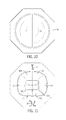
- FIG. 10 is an opaque output-side plan view of the lens of FIG. 8 .
- FIG. 11 is an opaque board-side plan view of the lens of FIG. 8 .
- FIG. 12 is an opaque lateral elevation of the lens of FIG. 8 .
- FIG. 13 is an opaque front elevation of the lens of FIG. 8 .
- FIG. 14 is an opaque back elevation of the lens of FIG. 8 .
- FIG. 15 is a side-to-side sectional view of the lens of FIG. 1 taken along section 15 - 15 shown in FIG. 3 .
- FIG. 16 is a front-to-back sectional view of the lens of FIG. 1 taken along section 16 - 16 shown in FIG. 4 .
- FIG. 17 is another side-to-side sectional view schematically illustrating lateral aspects of the near-field light distribution of the lens.
- FIG. 18 is a ray-trace schematically illustrating far-field lateral light distribution of the lens as shown in FIG. 17 .
- FIG. 19 is another front-to-back sectional view schematically illustrating aspects of the near-field forward and rearward light distribution of the lens.
- FIG. 20 is a ray-trace schematically illustrating far-field forward and rearward light distribution of the lens as shown in FIG. 19 .
- FIG. 21 is a front view of a three-dimensional polar intensity distribution by a lens according to the present invention.
- FIG. 22 is a side view of a three-dimensional polar intensity distribution by a lens according to the present invention.
- FIG. 23 is another transparent perspective view of the embodiment of the lens of FIG. 1 showing the lens from the back side.
- FIG. 24 is a two-dimensional top view ISO plot of luminance intensity by a lens according to the present invention on an illuminated surface.
- FIG. 25 is a photographic luminance rendering of a 14′ ⁇ 48′ billboard.
- FIG. 26 is a schematic illuminance view of a 14′ ⁇ 48′ billboard.
- FIG. 27 is an enlarged perspective view of one example of an LED package and including an array of eight LEDs on a submount and an asymmetric primary lens overmolded over the LED array.
- FIG. 28 is an enlarged perspective view of another example of an LED package and including an array of forty-eight LEDs on a submount and an asymmetric primary lens overmolded over the LED array.
- FIG. 29 is an enlarged perspective of yet another example of an LED package which has a single LED on a submount with a hemispheric primary lens overmolded over the LED.
- FIG. 30 is an enlarged side view of the LED package of FIG. 29 .
- FIG. 31 is an enlarged top view of the LED package of FIG. 29 .
- FIG. 32 is an enlarged top view of another exemplary LED package including an array of four LEDs on a submount and a hemispheric primary lens overmolded over the LED array such that the axis of the primary lens is offset from the axis of the LED array.
- FIG. 33 is a side-to-side sectional view of one embodiment of a lighting apparatus including a plurality of lenses over a plurality of light sources and schematically illustrating lateral aspects of the near-field light distribution of such lighting apparatus.
- FIG. 34 is a side-to-side sectional view of another embodiment of the lighting apparatus including a one-piece lensing member incorporating a plurality of the lenses each according to the present invention.
- FIGS. 1-26 show aspects of an exemplary embodiment of a lens 10 in accordance with this invention.
- Lens 10 is configured for directing light from a light source 20 on a board and defining an axis 6 .
- the light source may be an LED emitter which includes a single LED (or a closely-spaced group of LEDs) mounted either directly on the board or in the form of an LED package with the LED(s) on a submount on the board.
- a primary lens may be disposed over the LED(s).
- lens 10 is a secondary lens placed over the primary lens as seen in FIGS. 17 and 19 .
- FIGS. 1-7, 15 and 17 illustrate lens 10 which includes a board-adjacent base 11 spaced from and around axis 6 , an inner surface 30 , an intermediate surface 40 and an outer output surface 50 .
- outer output surface 50 is configured for refracting light received from inner surface 30 and intermediate surface 40 .
- base 11 forms an opening 12 into a light-receiving cavity 13 defined by inner surface 30 .
- FIGS. 3-7 show lens 10 being bilaterally symmetric in a front-to-back direction.
- inner surface 30 includes substantially planar front and back surface portions 31 and 32 and an end surface portion 33 spanning cavity 13 between front and back surface portions 31 and 32 .
- FIGS. 2 and 23 best illustrate each of front and back surface portions 31 and 32 extending from opening 12 to terminate at end surface portion 33 .
- inner surface 30 also includes a pair of substantially planar lateral surface portions 34 each extending from opening 12 between front and back surface portions 31 and 32 .
- FIGS. 5-7, 15-17 and 19 best show, each of front and back surface portions 31 and 32 being substantially parallel to axis 6 .
- FIGS. 1-4 and 23 show that inner front and back surface portions 31 and 32 are substantially orthogonal to inner lateral surface portion 34 .
- FIGS. 4 and 11 illustrate cavity opening 12 substantially rectangular with inner front, back and lateral surface portions 31 , 32 and 34 , respectively, each extending from one of four sides of opening 12 .
- Rounded corners 120 of opening 12 and 130 of cavity 13 provide advantages during manufacturing of lens 10 by facilitating accurate molding of the lens surfaces.
- end surface portion 33 includes front and back segments 35 and 36 each extending inwardly from front and back surface portions 31 and 32 , respectively.
- Back segment 36 extends from back surface portion 32 in a direction toward base 11
- front segment 35 extends from front surface portion 31 in a direction toward base 11 .
- FIGS. 1, 6, 7 and 23 show each of front and back segments 35 and 36 of end surface portion 33 extending inwardly from the opposite inner lateral surface portions 34 to positions progressively farther from base 11 .
- Back segment 36 extends to positions farther from base 11 than front segment 35 , as best seen in FIG. 16 .
- Each of segments 35 and 36 are angled with respect to the other, as seen in FIGS. 16 and 23 .
- Such angled configuration provides initial spreading of high concentration of light emitted within about 30° angle around axis 6 by spreading the light away from the hot spot location immediately about axis 6 and removing so-called hot spots along axis 6 by refracting the light away from the hot spot location immediately about axis 6 , as seen in FIG. 19 .
- front segment 35 includes a substantially concave middle portion 351 and a pair of opposite substantially convex lateral portions 352 and adjoining substantially concave middle portion 351 .
- Back segment 36 also includes a substantially concave middle portion 361 and a pair of opposite substantially convex lateral portions 362 and adjoining substantially convex middle portion 361 .
- the concave shape of middle portions 351 and 361 end surface portion 33 provides lateral spread of light emitted within about a 50° angle around emitter axis 6 , thereby providing broad light distribution (schematically shown in FIG. 17 ) beneficial for wide-lateral angle illumination patterns.
- the convex shape of lateral portions 352 and 362 provides initial direction of light emitted along angles close to board 21 toward useful angles between board 21 and axis 6 .
- FIG. 19 also shows that intermediate surface 40 is positioned and configured for total internal reflection (TIR) of light received from front and back inner surface portions 32 and 33 toward outer output surface 50 .
- intermediate surface 40 includes front and back reflective surface portions 41 and 42 .
- FIG. 19 shows that front and back reflective surface portions 41 and 42 are positioned and configured to receive light from front and back inner surface portions 31 and 32 , respectively, and reflect such light through TIR toward outer output surface 50 .
- front and back reflective surface portions 41 and 42 extend from base 11 away from axis 6 radially outwardly of front and back inner surface portions 31 and 32 , respectively. It is further seen in FIGS.
- FIGS. 4, 6, 7 and 11 show that front and back reflecting surface portions 41 and 42 are bilaterally symmetric.
- back reflecting surface portion 42 terminates at a greater distance 43 from base 11 than front reflecting surface portion 41 . It is best seen in FIG. 16 that back reflecting surface portion 42 also terminates at a greater distance 442 from axis 6 than distance 441 at which front reflecting surface portion 41 terminates from axis 6 .
- FIGS. 2, 9, 11 and 15 show intermediate surface 40 further includes a pair of intermediate lateral surface portions 45 each adjoining front and back reflective surface portions 41 and 42 such that intermediate surface 40 extends continuously around inner surface 30 .
- Front and back reflective surface portions 41 and 42 are at distances from base 11 which are greatest along front and back 1 and 2 , respectively, and gradually decrease toward lateral surface portions 45 .
- FIG. 17 shows intermediate lateral surface portions 45 positioned and configured to be substantially free of receiving light from inner surface 30 .
- intermediate lateral surface portions 45 have substantially identical lateral curvatures 450 which differ from configurations of front and back curvatures 410 and 420 .
- FIGS. 2, 4, 9 and 11 also show that rounded corners 140 of a base edge 14 of intermediate surface 40 provide smooth transition from lateral curvatures 450 to front and back curvatures 410 and 420 of intermediate surface 40 .
- FIGS. 1, 5-8, 13-17, 19 and 23 show outer output surface 50 including a main output surface portion 51 transverse axis 6 . It is best shown in FIGS. 6, 7, 13-15, 19 and 23 that main-output surface portion 51 defines a pair of substantially convex lateral sectors 52 with a front-to-back concavity 53 therebetween for refracting lateral light received from inner surface 30 further laterally away from axis 6 , as seen in FIG. 17 , to facilitate wide lateral-angle light distribution as illustrated in FIGS. 18 and 21 .
- FIG. 19 shows main output surface portion 51 configured for refracting forward and rearward light received from inner front and back surface portions 31 and 32 further away from axis 6 to facilitate uniform distribution of light, as seen in FIGS. 20 and 22 .
- main output surface 51 is also configured for refracting light received from front and back reflecting surface portions 41 and 42 toward axis 6 .
- outer output surface 50 includes an outer lateral surface portion 54 which extends from main output surface portion 51 toward base 11 .
- FIG. 17 illustrates outer lateral surface portion 54 configured for refracting light received from inner surface 30 toward axis 6 to facilitate uniformity of the illumination pattern seen in FIGS. 25 and 26 .
- outer lateral surface portion 54 is substantially parallel to axis 6 .
- FIGS. 5, 15-17 and 19 show that outer lateral surface portion 54 is defined by an outer surrounding wall 15 which extends from main output surface portion 51 and intermediate surface 40 toward board 21 .
- outer lateral surface portion 54 has a substantially right cylindrical shape of substantially circular cross-sections taken in planes parallel to base 11 . It should be understood that many other configurations for the outer surrounding wall are possible, including, without limitation surfaces generated by movement of a line which is other than straight.
- the outer lateral surface may have various annular shapes, including shapes having different cross-sectional configurations at different positions therealong or shapes angled with respect to the emitter axis.
- FIGS. 1-17 also show lens 10 including an outward flange 16 extending from outer surrounding wall 15 away from axis 16 .
- Outward flange 16 is shown as having an octagonal perimeter which facilitates mounting of the lens during light-fixture assembly.
- Flange 16 best shown in FIGS. 3, 4, 10 and 11 , also has a lens-type-identifying marking 18 and a locator label 17 which references the lens location in an LED-array module.
- An orientation between marking 18 and label 17 indicates front 1 and back 2 of the light distribution shown in FIG. 22 .
- These markings are preferably readable by robotic equipment for correct lens placement and orientation during light-fixture assembly.
- FIGS. 1-17 also show lens 10 including an outward flange 16 extending from outer surrounding wall 15 away from axis 16 .
- Outward flange 16 is shown as having an octagonal perimeter which facilitates mounting of the lens during light-fixture assembly.
- Flange 16 best shown in FIGS. 3, 4, 10 and 11 , also has
- FIGS. 17 and 19 show that such spacing allows positioning of plane 110 at the same level with the LED(s) of light source 20 for most efficient capturing of emitted light by inner surface 30 .
- Another aspect of this invention involves a lighting apparatus which includes a plurality of LED light sources spaced along a circuit board, each of the LED light sources defining an axis.
- the lighting apparatus includes a plurality of the inventive lenses according to the present invention, each lens over a corresponding one of the LED light sources.
- the lighting apparatus includes a one-piece lensing member which includes a plurality of lens portions interconnected by a flange portion.
- each of the lens portions includes one of the plurality of the lenses.
- inventive lens 10 has the configuration which is described above and which allows for molding of lens 10 in a single-piece mold.
- the lens configuration preferably permits easy removal of the lens from the mold without the need for separating the mold pieces as is the case with some lenses that require multiple-piece molds.
- the inventive lens can be simply pulled out of the mold.
- FIGS. 33 and 34 show another aspect of this invention which involves a lighting apparatus 100 including a plurality of LED light sources 20 spaced along a circuit board 21 A.
- Lighting apparatus 100 includes a plurality of inventive lenses 10 each over a corresponding one of LED light sources 20 .
- FIG. 34 shows lighting apparatus 100 A which includes a one-piece lensing member 101 which includes a plurality of lens portions 102 interconnected by a flange portion 103 .
- Each of lens portions 102 includes one of the plurality of lenses 10 .
- FIGS. 25 and 26 schematically illustrate lens 10 being used in light fixtures installed for illumination of a surface 3 such as a billboard of a transportation sign. These figures show that light is directed for an extended lateral distance along the longer dimension of illuminated surface 3 such that a minimal number of light fixtures need to be installed.
- FIG. 26 shows only two light fixtures illuminating the entire surface 3 .
- a plurality of LEDs or LED arrays may be disposed directly on a common submount in spaced relationship between the LEDs or LED arrays. This type of LED emitters is sometimes referred to as chip-on-board LEDs.
- each of the LED emitters is on a submount and each of the submounts is mounted on the circuit board.
- each of the LEDs or LED arrays may be overmolded with a respective primary lens.
- Lens 10 according to the present invention may form the primary lens over a respective one of the LEDs or LED arrays.
- a plurality of inventive lenses 10 form secondary lenses each over a respective one primary lenses.
- the plurality of lenses 10 may be molded as a single piece which may have a single flange surrounding each of the plurality of lenses 10 , as seen in FIG. 34 .
- FIGS. 27-32 show light source 20 including at least one light-emitting diode (LED) 22 .
- Light source 20 may be a light emitter in the form of an LED package 23 which has a primary lens 24 over the at least one LED 22 .
- lens 10 is a secondary lens placed over primary lens 24 .
- Light emitter 20 may be of the type illustrated in FIGS. 29-31 which show LED package 23 D with single LED 22 on a submount 26 and hemispheric primary lens 24 D coaxially overmolded on submount 26 over LED 22 .
- FIGS. 27 and 28 illustrate exemplary LED packages 23 A and 23 B each including an array of LEDs 22 on an LED-populated area 25 which has an aspect ratio greater than 1 , and primary lens 24 being overmolded on a submount 26 over LED-populated area 25 .
- the array may include LEDs 22 emitting different-wavelength light of different colors such as including red LEDs along with light green or other colors to achieve natural white light.
- Light emitters of the type as LED packages 23 A and 23 B are described in detail in application Ser. No. 13/441,558, filed on Apr. 6, 2012, and in application Ser. No. 13/441,620, filed on Apr. 6, 2012. The contents of both applications are incorporated herein by reference in their entirety.
- FIGS. 27, 28 and 32 illustrate versions of LED light emitter 20 configured to refract LED-emitted light in a forward direction 1 (i.e., toward front 1 ).
- each LED package 23 A, 23 B and 23 C each LED array defines an emitter axis.
- FIGS. 27 and 28 illustrate primary lens 24 A configured to refract LED-emitted light forward.
- FIG. 32 shows hemispheric primary lens 24 C having a centerline 240 offset from the emitter axis. It should be understood that for higher efficiency, LED emitter 20 may have a primary lens which is both has its centerline offset from the emitter axis and is shaped for refraction of LED-emitted light toward preferential side 2 .
- primary lens 24 A is shown as asymmetric.
Abstract
Description
Claims (30)
Priority Applications (3)
| Application Number | Priority Date | Filing Date | Title |
|---|---|---|---|
| US13/842,776 US9541258B2 (en) | 2012-02-29 | 2013-03-15 | Lens for wide lateral-angle distribution |
| PCT/US2013/039688 WO2013169643A1 (en) | 2012-05-07 | 2013-05-06 | Lens for wide lateral-angle distribution |
| CN201380024053.0A CN104302973B (en) | 2012-05-07 | 2013-05-06 | For the lens of wide lateral angles distribution |
Applications Claiming Priority (3)
| Application Number | Priority Date | Filing Date | Title |
|---|---|---|---|
| US13/408,882 US9541257B2 (en) | 2012-02-29 | 2012-02-29 | Lens for primarily-elongate light distribution |
| US13/466,076 US10408429B2 (en) | 2012-02-29 | 2012-05-07 | Lens for preferential-side distribution |
| US13/842,776 US9541258B2 (en) | 2012-02-29 | 2013-03-15 | Lens for wide lateral-angle distribution |
Related Parent Applications (1)
| Application Number | Title | Priority Date | Filing Date |
|---|---|---|---|
| US13/466,076 Continuation-In-Part US10408429B2 (en) | 2012-02-29 | 2012-05-07 | Lens for preferential-side distribution |
Publications (2)
| Publication Number | Publication Date |
|---|---|
| US20130223072A1 US20130223072A1 (en) | 2013-08-29 |
| US9541258B2 true US9541258B2 (en) | 2017-01-10 |
Family
ID=49002681
Family Applications (1)
| Application Number | Title | Priority Date | Filing Date |
|---|---|---|---|
| US13/842,776 Active 2033-09-20 US9541258B2 (en) | 2012-02-29 | 2013-03-15 | Lens for wide lateral-angle distribution |
Country Status (1)
| Country | Link |
|---|---|
| US (1) | US9541258B2 (en) |
Cited By (3)
| Publication number | Priority date | Publication date | Assignee | Title |
|---|---|---|---|---|
| US10190736B1 (en) * | 2016-04-22 | 2019-01-29 | Cooper Technologies Company | Apparatus for providing off-axis illumination |
| US10741107B2 (en) | 2013-12-31 | 2020-08-11 | Ultravision Technologies, Llc | Modular display panel |
| US10891881B2 (en) | 2012-07-30 | 2021-01-12 | Ultravision Technologies, Llc | Lighting assembly with LEDs and optical elements |
Families Citing this family (7)
| Publication number | Priority date | Publication date | Assignee | Title |
|---|---|---|---|---|
| US9080739B1 (en) * | 2012-09-14 | 2015-07-14 | Cooper Technologies Company | System for producing a slender illumination pattern from a light emitting diode |
| JP6145817B2 (en) * | 2013-04-12 | 2017-06-14 | パナソニックIpマネジメント株式会社 | Lighting device |
| KR102142388B1 (en) | 2014-02-06 | 2020-08-10 | 삼성디스플레이 주식회사 | Led light source package |
| WO2016142179A1 (en) * | 2015-03-06 | 2016-09-15 | Koninklijke Philips N.V. | Led-based lighting device with asymmetrically distributed led chips |
| CN107850764B (en) * | 2015-04-14 | 2020-10-23 | 飞利浦照明控股有限公司 | Forward stroke asymmetric optics design |
| EP3415812A1 (en) * | 2017-06-13 | 2018-12-19 | Philips Lighting Holding B.V. | A lens for a light source, for providing an asymmetric output, and a lighting unit using the lens |
| CZ2017734A3 (en) * | 2017-11-14 | 2019-05-22 | Varroc Lighting Systems, s.r.o. | Vehicle lighting equipment |
Citations (202)
| Publication number | Priority date | Publication date | Assignee | Title |
|---|---|---|---|---|
| US1404004A (en) | 1921-01-07 | 1922-01-17 | Gen Electric | Searchlight window |
| US1535486A (en) | 1922-08-28 | 1925-04-28 | James W Lundy | Electric-lamp bulb |
| US2007033A (en) | 1932-01-02 | 1935-07-02 | Holophane Co Inc | Lighting unit |
| US2212876A (en) | 1938-11-05 | 1940-08-27 | Albert L Chauvet | Nonglare headlight |
| US2254961A (en) | 1937-08-21 | 1941-09-02 | George M Cressaty | Unitary lens system |
| US2356654A (en) | 1944-08-22 | Catadioptric lens | ||
| US2802097A (en) | 1952-09-16 | 1957-08-06 | Holophane Co Inc | Luminaires |
| US2908197A (en) | 1954-01-29 | 1959-10-13 | Westinghouse Air Brake Co | Wide angle lenses |
| US3497687A (en) | 1967-08-30 | 1970-02-24 | Donald W Hermann | Lens attachment for automobile headlights |
| US3625615A (en) | 1969-04-01 | 1971-12-07 | Zeiss Stiftung | A device for spectral dispersion of light employing a predispersion prism and a grafting monochromator |
| US4186995A (en) | 1978-03-30 | 1980-02-05 | Amp Incorporated | Light device, lens, and fiber optic package |
| US4254453A (en) | 1978-08-25 | 1981-03-03 | General Instrument Corporation | Alpha-numeric display array and method of manufacture |
| US4336580A (en) | 1978-08-25 | 1982-06-22 | General Instrument Corporation | Alpha-numeric display array and method of manufacture |
| US4345308A (en) | 1978-08-25 | 1982-08-17 | General Instrument Corporation | Alpha-numeric display array and method of manufacture |
| JPS60199746A (en) | 1984-03-23 | 1985-10-09 | Nissan Motor Co Ltd | Lighting fixture for car |
| WO1986000146A1 (en) | 1984-06-07 | 1986-01-03 | Ernst Granström Ab | Light diffusing lens |
| JPS61160328A (en) | 1984-12-30 | 1986-07-21 | Stanley Electric Co Ltd | Automobile rear spoiler |
| JPS61185980A (en) | 1985-02-13 | 1986-08-19 | Stanley Electric Co Ltd | Light emitting diode |
| JPS61214000A (en) | 1985-03-19 | 1986-09-22 | スタンレー電気株式会社 | Omnidirectional signal lamp |
| JPS61214485A (en) | 1985-03-19 | 1986-09-24 | Stanley Electric Co Ltd | Led for light source |
| US4650998A (en) | 1984-12-10 | 1987-03-17 | Siemens Corporate Research & Support, Inc. | Highly aligned optical device |
| US4767172A (en) | 1983-01-28 | 1988-08-30 | Xerox Corporation | Collector for an LED array |
| US4845600A (en) | 1988-03-14 | 1989-07-04 | Koito Manufacturing Co., Ltd. | Vehicle spoiler lamp device |
| US4862330A (en) | 1987-09-21 | 1989-08-29 | Koito Manufacturing Co., Ltd. | Vehicle lamp |
| US4935665A (en) | 1987-12-24 | 1990-06-19 | Mitsubishi Cable Industries Ltd. | Light emitting diode lamp |
| US4941072A (en) | 1988-04-08 | 1990-07-10 | Sanyo Electric Co., Ltd. | Linear light source |
| US5001609A (en) | 1988-10-05 | 1991-03-19 | Hewlett-Packard Company | Nonimaging light source |
| US5013144A (en) | 1988-10-15 | 1991-05-07 | Hewlett-Packard Company | Light source having a multiply conic lens |
| US5014165A (en) | 1988-12-22 | 1991-05-07 | Koito Manufacturing Co., Ltd. | Glass-made lens |
| US5062027A (en) | 1989-02-09 | 1991-10-29 | Koito Manufacturing Co., Ltd. | Automobile signal lamp |
| US5127728A (en) | 1990-01-18 | 1992-07-07 | The Aerospace Corporation | Compact prism spectrograph suitable for broadband spectral surveys with array detectors |
| US5140220A (en) | 1985-12-02 | 1992-08-18 | Yumi Sakai | Light diffusion type light emitting diode |
| US5174649A (en) | 1991-07-17 | 1992-12-29 | Precision Solar Controls Inc. | Led lamp including refractive lens element |
| USRE34254E (en) | 1989-10-05 | 1993-05-18 | Dialight Corporation | Surface mounted LED package |
| US5289082A (en) | 1990-09-07 | 1994-02-22 | Kabushiki Kaisha Toshiba | LED lamp |
| US5302778A (en) | 1992-08-28 | 1994-04-12 | Eastman Kodak Company | Semiconductor insulation for optical devices |
| US5349504A (en) | 1993-07-12 | 1994-09-20 | Dialight Corporation | Multi-level lightpipe design for SMD LEDs |
| GB2282700A (en) | 1993-10-01 | 1995-04-12 | John Herbert Brown | Optical element for use with an LED |
| US5592578A (en) | 1995-11-01 | 1997-01-07 | Hewlett-Packard Company | Peripheral optical element for redirecting light from an LED |
| US5784209A (en) | 1995-05-25 | 1998-07-21 | Nikon Corporation | Multi-axis optical lens |
| US5813752A (en) | 1997-05-27 | 1998-09-29 | Philips Electronics North America Corporation | UV/blue LED-phosphor device with short wave pass, long wave pass band pass and peroit filters |
| US5813743A (en) | 1995-03-27 | 1998-09-29 | Fuji Photo Film Co., Ltd. | Lighting unit |
| US5865529A (en) | 1997-03-10 | 1999-02-02 | Yan; Ellis | Light emitting diode lamp having a spherical radiating pattern |
| US5894195A (en) | 1996-05-03 | 1999-04-13 | Mcdermott; Kevin | Elliptical axial lighting device |
| US5894196A (en) | 1996-05-03 | 1999-04-13 | Mcdermott; Kevin | Angled elliptical axial lighting device |
| US5898267A (en) | 1996-04-10 | 1999-04-27 | Mcdermott; Kevin | Parabolic axial lighting device |
| US5924788A (en) | 1997-09-23 | 1999-07-20 | Teledyne Lighting And Display Products | Illuminating lens designed by extrinsic differential geometry |
| US5939996A (en) | 1996-03-29 | 1999-08-17 | Rolls-Royce Power Engineering Plc | Display sign and an optical element for use in the same |
| WO1999050596A2 (en) | 1998-03-26 | 1999-10-07 | Otkrytoe Aktsionernoe Obschestvo Lomo | Illumination device for generating non-symmetric light beam, optical lens array and optical lens |
| US5995291A (en) | 1996-03-25 | 1999-11-30 | Olympus Optical Co., Ltd. | Optical system and optical device comprising diffractive optical element |
| WO2000024062A1 (en) | 1998-10-21 | 2000-04-27 | Koninklijke Philips Electronics N.V. | Led module and luminaire |
| US6097549A (en) | 1997-08-12 | 2000-08-01 | Breault Research Organization, Inc. | Bireflective lens element |
| US6229160B1 (en) | 1997-06-03 | 2001-05-08 | Lumileds Lighting, U.S., Llc | Light extraction from a semiconductor light-emitting device via chip shaping |
| US6244727B1 (en) | 1999-09-27 | 2001-06-12 | American Signal Company | Optic lens cell and illuminated signage having a cell array |
| EP1107210A2 (en) | 1999-12-09 | 2001-06-13 | SWARCO FUTURIT Verkehrssignalsysteme Ges.m.b.H. | LED signal emitter comprising a plurality of LED zones |
| US6250787B1 (en) | 1998-12-15 | 2001-06-26 | Koito Manufacturing Co., Ltd. | Vehicle lamp fixture |
| US6273596B1 (en) | 1997-09-23 | 2001-08-14 | Teledyne Lighting And Display Products, Inc. | Illuminating lens designed by extrinsic differential geometry |
| US6274924B1 (en) | 1998-11-05 | 2001-08-14 | Lumileds Lighting, U.S. Llc | Surface mountable LED package |
| US6283613B1 (en) | 1999-07-29 | 2001-09-04 | Cooper Technologies Company | LED traffic light with individual LED reflectors |
| US6296376B1 (en) | 1998-08-12 | 2001-10-02 | Stanley Electric Co., Ltd. | Led lamp having a prismatically-cut modifier |
| US6361190B1 (en) | 1999-06-25 | 2002-03-26 | Mcdermott Kevin | Large surface LED lighting device |
| US6361192B1 (en) | 1999-10-25 | 2002-03-26 | Global Research & Development Corp | Lens system for enhancing LED light output |
| US6443594B1 (en) | 2000-03-31 | 2002-09-03 | Koninklijke Philips Electronics N.V. | One-piece lens arrays for collimating and focusing light and led light generators using same |
| US6473238B1 (en) | 2000-03-17 | 2002-10-29 | Stephen Daniell | Lens arrays |
| US6481130B1 (en) | 2000-08-11 | 2002-11-19 | Leotek Electronics Corporation | Light emitting diode linear array with lens stripe for illuminated signs |
| US6498355B1 (en) | 2001-10-09 | 2002-12-24 | Lumileds Lighting, U.S., Llc | High flux LED array |
| US6502956B1 (en) | 1999-03-25 | 2003-01-07 | Leotek Electronics Corporation | Light emitting diode lamp with individual LED lenses |
| US6504301B1 (en) | 1999-09-03 | 2003-01-07 | Lumileds Lighting, U.S., Llc | Non-incandescent lightbulb package using light emitting diodes |
| US6536923B1 (en) | 1998-07-01 | 2003-03-25 | Sidler Gmbh & Co. | Optical attachment for a light-emitting diode and brake light for a motor vehicle |
| US6541800B2 (en) | 2001-02-22 | 2003-04-01 | Weldon Technologies, Inc. | High power LED |
| US6547423B2 (en) | 2000-12-22 | 2003-04-15 | Koninklijke Phillips Electronics N.V. | LED collimation optics with improved performance and reduced size |
| US6550940B2 (en) | 2000-07-28 | 2003-04-22 | Toyoda Gosei Co,., Ltd. | Lighting device |
| US6554451B1 (en) | 1999-08-27 | 2003-04-29 | Lumileds Lighting U.S., Llc | Luminaire, optical element and method of illuminating an object |
| US6560038B1 (en) | 2001-12-10 | 2003-05-06 | Teledyne Lighting And Display Products, Inc. | Light extraction from LEDs with light pipes |
| US6598998B2 (en) | 2001-05-04 | 2003-07-29 | Lumileds Lighting, U.S., Llc | Side emitting light emitting device |
| US6601962B1 (en) | 1999-05-11 | 2003-08-05 | Nichia Corporation | Surface light emitting device |
| US6607286B2 (en) | 2001-05-04 | 2003-08-19 | Lumileds Lighting, U.S., Llc | Lens and lens cap with sawtooth portion for light emitting diode |
| US6616299B2 (en) | 2001-02-02 | 2003-09-09 | Gelcore Llc | Single optical element LED signal |
| US6637921B2 (en) | 2001-09-28 | 2003-10-28 | Osram Sylvania Inc. | Replaceable LED bulb with interchangeable lens optic |
| US6679621B2 (en) | 2002-06-24 | 2004-01-20 | Lumileds Lighting U.S., Llc | Side emitting LED and lens |
| US6682211B2 (en) | 2001-09-28 | 2004-01-27 | Osram Sylvania Inc. | Replaceable LED lamp capsule |
| US20040037076A1 (en) | 2002-07-17 | 2004-02-26 | Sharp Kabushiki Kaisha | Light emitting diode lamp and light emitting diode display unit |
| US6730940B1 (en) | 2002-10-29 | 2004-05-04 | Lumileds Lighting U.S., Llc | Enhanced brightness light emitting device spot emitter |
| US20040114355A1 (en) | 2001-05-30 | 2004-06-17 | Alexander Rizkin | In-pavement directional LED luminaire |
| US20040156209A1 (en) | 2003-02-10 | 2004-08-12 | Hiroyuki Ishida | Vehicular headlamp and optical unit |
| US20040207999A1 (en) | 2003-03-14 | 2004-10-21 | Toyoda Gosei Co., Ltd. | LED package |
| US6808293B2 (en) | 2001-06-27 | 2004-10-26 | Nichia Corporation | LED lamp with prismatic cover lens |
| US20040212291A1 (en) | 2000-03-14 | 2004-10-28 | Keuper Matthijs Hendrik | Light-emitting diode, lighting device and method of manufacturing same |
| US6837605B2 (en) | 2001-11-28 | 2005-01-04 | Osram Opto Semiconductors Gmbh | Led illumination system |
| US6851835B2 (en) | 2002-12-17 | 2005-02-08 | Whelen Engineering Company, Inc. | Large area shallow-depth full-fill LED light assembly |
| US20050073849A1 (en) | 2003-10-06 | 2005-04-07 | Greg Rhoads | Light source using light emitting diodes and an improved method of collecting the energy radiating from them |
| US20050083699A1 (en) | 2003-08-12 | 2005-04-21 | Greg Rhoads | Apparatus and method for using emitting diodes (LED) in a side-emitting device |
| US6896381B2 (en) | 2002-10-11 | 2005-05-24 | Light Prescriptions Innovators, Llc | Compact folded-optics illumination lens |
| US6903376B2 (en) | 1999-12-22 | 2005-06-07 | Lumileds Lighting U.S., Llc | Selective placement of quantum wells in flipchip light emitting diodes for improved light extraction |
| US6918677B2 (en) | 1999-09-15 | 2005-07-19 | Michael Shipman | Illuminated keyboard |
| US6924943B2 (en) | 2002-12-02 | 2005-08-02 | Light Prescriptions Innovators, Llc | Asymmetric TIR lenses producing off-axis beams |
| US6929384B2 (en) | 2001-02-09 | 2005-08-16 | Nichia Corporation | Led indicator lamp |
| US20050179041A1 (en) | 2004-02-18 | 2005-08-18 | Lumileds Lighting U.S., Llc | Illumination system with LEDs |
| US20050205878A1 (en) | 2004-02-26 | 2005-09-22 | Peter Kan | Apparatus for forming an asymmetric illumination beam pattern |
| US6948840B2 (en) | 2001-11-16 | 2005-09-27 | Everbrite, Llc | Light emitting diode light bar |
| US20050224826A1 (en) | 2004-03-19 | 2005-10-13 | Lumileds Lighting, U.S., Llc | Optical system for light emitting diodes |
| US6955451B2 (en) | 2003-08-25 | 2005-10-18 | Osram Sylvania Inc. | Lamp with LED substrates supported by heat conductive post, and method of making such lamp |
| US20050281047A1 (en) | 2004-06-16 | 2005-12-22 | Osram Sylvania Inc. | LED lamp and lamp/reflector assembly |
| US6987613B2 (en) | 2001-03-30 | 2006-01-17 | Lumileds Lighting U.S., Llc | Forming an optical element on the surface of a light emitting device for improved light extraction |
| US20060013002A1 (en) | 2004-07-16 | 2006-01-19 | Osram Sylvania Inc. | Light emitting diode disc optic with heat sink housing |
| US20060013000A1 (en) | 2004-07-16 | 2006-01-19 | Osram Sylvania Inc. | Flat mount for light emitting diode source |
| US6991355B1 (en) | 2004-06-16 | 2006-01-31 | Osram Sylvania Inc. | light emitting diode lamp with light pipes |
| US6995402B2 (en) | 2003-10-03 | 2006-02-07 | Lumileds Lighting, U.S., Llc | Integrated reflector cup for a light emitting device mount |
| US20060044806A1 (en) | 2004-08-25 | 2006-03-02 | Abramov Vladimir S | Light emitting diode system packages |
| US7009213B2 (en) | 2003-07-31 | 2006-03-07 | Lumileds Lighting U.S., Llc | Light emitting devices with improved light extraction efficiency |
| US20060067640A1 (en) | 2004-09-24 | 2006-03-30 | Min-Hsun Hsieh | Illumination package |
| US7021797B2 (en) | 2003-05-13 | 2006-04-04 | Light Prescriptions Innovators, Llc | Optical device for repositioning and redistributing an LED's light |
| US20060082999A1 (en) | 2004-10-18 | 2006-04-20 | Klein W R | Refractive clamp/optic for light emitting diode |
| US20060083000A1 (en) | 2004-10-18 | 2006-04-20 | Ju-Young Yoon | Light emitting diode and lens for the same |
| US7042021B2 (en) | 2003-10-02 | 2006-05-09 | Citizen Electronics Co., Ltd. | Light emitting diode with reflection cup |
| US20060105482A1 (en) | 2004-11-12 | 2006-05-18 | Lumileds Lighting U.S., Llc | Array of light emitting devices to produce a white light source |
| US7053419B1 (en) | 2000-09-12 | 2006-05-30 | Lumileds Lighting U.S., Llc | Light emitting diodes with improved light extraction efficiency |
| US7064355B2 (en) | 2000-09-12 | 2006-06-20 | Lumileds Lighting U.S., Llc | Light emitting diodes with improved light extraction efficiency |
| US7063441B2 (en) | 2003-07-02 | 2006-06-20 | Kramer Eric W | Soft light fixture |
| US7080932B2 (en) | 2004-01-26 | 2006-07-25 | Philips Lumileds Lighting Company, Llc | LED with an optical system to increase luminance by recycling emitted light |
| US7083313B2 (en) | 2004-06-28 | 2006-08-01 | Whelen Engineering Company, Inc. | Side-emitting collimator |
| US20060181902A1 (en) | 2004-12-27 | 2006-08-17 | Nichia Corporation | Optical guide and surface light emitting apparatus using the same |
| US20060186431A1 (en) | 2005-02-18 | 2006-08-24 | Nichia Corporation | Light emitting device provided with lens for controlling light distribution characteristic |
| US20060198144A1 (en) | 2005-03-07 | 2006-09-07 | Nichia Corporation | Planar light source and planar lighting apparatus |
| US7106523B2 (en) | 2002-01-11 | 2006-09-12 | Ultradent Products, Inc. | Optical lens used to focus led light |
| US7104672B2 (en) | 2004-10-04 | 2006-09-12 | A.L. Lightech, Inc. | Projection lens for light source arrangement |
| US7111972B2 (en) | 2004-06-23 | 2006-09-26 | Osram Sylvania Inc. | LED lamp with central optical light guide |
| US7114838B2 (en) | 2005-01-12 | 2006-10-03 | Au Optronics Corp. | Dish lens for backlight module and light emitting diode |
| US7118236B2 (en) | 2004-08-11 | 2006-10-10 | Samsung Electro-Mechanics Co., Ltd. | Light emitting diode lens and backlight apparatus having the same |
| US7118262B2 (en) | 2004-07-23 | 2006-10-10 | Cree, Inc. | Reflective optical elements for semiconductor light emitting devices |
| US7121691B2 (en) | 2004-09-22 | 2006-10-17 | Osram Sylvania Inc. | Lamp assembly with interchangeable light distributing cap |
| WO2006109113A2 (en) | 2005-04-12 | 2006-10-19 | Acol Technologies Sa | Primary optic for a light emitting diode |
| US7125160B2 (en) | 2004-10-29 | 2006-10-24 | Applied Innovative Technologies, Inc. | Led light collection and uniform transmission system using a conical reflector with a roughed up inner surface |
| US7125143B2 (en) | 2003-07-31 | 2006-10-24 | Osram Opto Semiconductors Gmbh | LED module |
| WO2006111805A1 (en) | 2005-04-16 | 2006-10-26 | Acol Technologies Sa | Optical light source having displaced axes |
| US7153000B2 (en) | 2004-08-12 | 2006-12-26 | Samsung Electro-Mechanics Co., Ltd. | Multi-lens light emitting diode |
| US7153002B2 (en) | 2004-10-15 | 2006-12-26 | Samsung Electro-Mechanics Co., Ltd. | Lens for LED light sources |
| US20070019416A1 (en) | 2005-07-19 | 2007-01-25 | Samsung Electro-Mechanics Co., Ltd. | Light emitting diode package having dual lens structure for lateral light emission |
| US7172324B2 (en) | 2004-01-05 | 2007-02-06 | Leotek Electronics Corporation | Internally illuminated light panel with LED modules having light redirecting devices |
| WO2007018927A2 (en) | 2005-07-22 | 2007-02-15 | Illumination Management Solutions, Inc. | A light-conducting pedestal configuration for an led |
| US7182497B2 (en) | 2004-09-24 | 2007-02-27 | Samsung Electronics Co., Ltd. | Illumination unit using LED and image projecting apparatus employing the same |
| US20070058369A1 (en) | 2005-01-26 | 2007-03-15 | Parkyn William A | Linear lenses for LEDs |
| US20070097693A1 (en) | 2005-05-09 | 2007-05-03 | Erco Leuchten Gmbh | Light fixture with two-region light diffuser |
| US7213945B2 (en) | 2002-05-17 | 2007-05-08 | Ccs, Inc. | Light emitting diode and method for fabricating the same |
| US20070133209A1 (en) | 2005-12-09 | 2007-06-14 | Harvatek Corporation | Electrical lamp apparatus |
| US7246923B2 (en) | 2004-02-11 | 2007-07-24 | 3M Innovative Properties Company | Reshaping light source modules and illumination systems using the same |
| US7246931B2 (en) | 2004-12-15 | 2007-07-24 | Epistar Corporation | LED light source |
| US20070177389A1 (en) | 2006-01-17 | 2007-08-02 | Pickard Paul K | Volumetric downlight light fixture |
| US7254309B1 (en) | 2006-07-14 | 2007-08-07 | Coretronic Corporation | Side emitting LED and lens |
| US20070201225A1 (en) | 2006-02-27 | 2007-08-30 | Illumination Management Systems | LED device for wide beam generation |
| US7280288B2 (en) | 2004-06-04 | 2007-10-09 | Cree, Inc. | Composite optical lens with an integrated reflector |
| US20070258248A1 (en) | 2006-05-04 | 2007-11-08 | Duhe Jerry R Jr | Lighted lens housing for jewelers loupe |
| US20070263393A1 (en) | 2006-05-05 | 2007-11-15 | Led Lighting Fixtures, Inc. | Lighting device |
| US20070274667A1 (en) | 2006-05-10 | 2007-11-29 | Cree, Inc. | Methods and apparatus for directing light emitting diode output light |
| US7329029B2 (en) | 2003-05-13 | 2008-02-12 | Light Prescriptions Innovators, Llc | Optical device for LED-based lamp |
| US7348723B2 (en) | 2004-09-27 | 2008-03-25 | Enplas Corporation | Emission device, surface light source device, display and light flux control member |
| US7352011B2 (en) | 2004-11-15 | 2008-04-01 | Philips Lumileds Lighting Company, Llc | Wide emitting lens for LED useful for backlighting |
| US20080084693A1 (en) | 2006-10-10 | 2008-04-10 | Yanchers Corporation | Lighting system |
| US20080084701A1 (en) | 2006-09-21 | 2008-04-10 | Led Lighting Fixtures, Inc. | Lighting assemblies, methods of installing same, and methods of replacing lights |
| US20080101063A1 (en) | 2006-10-27 | 2008-05-01 | Teruo Koike | LED Lighting Fixture |
| US20080106907A1 (en) | 2006-10-23 | 2008-05-08 | Led Lighting Fixtures, Inc. | Lighting devices and methods of installing light engine housings and/or trim elements in lighting device housings |
| US20080130298A1 (en) | 2006-11-30 | 2008-06-05 | Led Lighting Fixtures, Inc. | Self-ballasted solid state lighting devices |
| US7410275B2 (en) | 2004-09-21 | 2008-08-12 | Lumination Llc | Refractive optic for uniform illumination |
| US7411742B1 (en) | 2007-02-20 | 2008-08-12 | Sekonix Co., Ltd. | Focusing lens for LED |
| US20080205061A1 (en) | 2005-04-28 | 2008-08-28 | Illumination Management Solutions, Inc. | Apparatus And Method Of Using A Led Light Source To Generate An Efficent, Narrow, High-Aspect Ratio Light Pattern |
| US20080239722A1 (en) | 2007-04-02 | 2008-10-02 | Ruud Lighting, Inc. | Light-Directing LED Apparatus |
| WO2008144672A1 (en) | 2007-05-21 | 2008-11-27 | Illumination Management Solutions, Inc. | An improved led device for wide beam generation and method of making the same |
| US20090067172A1 (en) | 2007-09-05 | 2009-03-12 | Masaru Inoue | Lighting apparatus |
| US20090086498A1 (en) | 2007-10-01 | 2009-04-02 | Patrick Jeffrey Condon | Method and apparatus for creating optical images |
| US20090097262A1 (en) | 2007-10-10 | 2009-04-16 | Cordelia Lighting, Inc. | Lighting fixture with recessed baffle trim unit |
| US7549769B2 (en) | 2005-08-30 | 2009-06-23 | Samsung Electro-Mechanics Co., Ltd. | LED lens for backlight |
| US20090290360A1 (en) | 2008-05-23 | 2009-11-26 | Ruud Lighting, Inc. | Lens with tir for off-axial light distribution |
| US20090298376A1 (en) | 2008-05-27 | 2009-12-03 | Ruud Lighting, Inc. | Method for led-module assembly |
| US20100014286A1 (en) | 2005-06-01 | 2010-01-21 | Kenji Yoneda | Light irradiation apparatus |
| US20100027271A1 (en) | 2008-08-01 | 2010-02-04 | Ruud Lighting, Inc. | Light-directing lensing member with improved angled light distribution |
| US20100039810A1 (en) | 2008-08-14 | 2010-02-18 | Cooper Technologies Company | LED Devices for Offset Wide Beam Generation |
| US20100073927A1 (en) | 2008-09-21 | 2010-03-25 | Ian Lewin | Lens for Solid-State Light-Emitting Device |
| US20100085763A1 (en) | 2007-01-26 | 2010-04-08 | Sic Divisione Elettronica S.R.L. | Lens for a light emitting diode and manufacturing method therefor |
| US20100085764A1 (en) | 2008-10-03 | 2010-04-08 | Ping-Han Chuang | Light distribution panel having light distribution curves formed of multiple faces |
| US20100110695A1 (en) | 2008-10-31 | 2010-05-06 | Masato Nakamura | Lighting lens and lighting device equipped with the same |
| US20100128488A1 (en) | 2008-11-21 | 2010-05-27 | Dbm Reflex Enterprises Inc. | Solid state optical illumination apparatus |
| US20100135028A1 (en) | 2007-08-09 | 2010-06-03 | Sharp Kabushiki Kaisha | Light emitting device and lighting device having the same |
| US7766509B1 (en) | 2008-06-13 | 2010-08-03 | Lumec Inc. | Orientable lens for an LED fixture |
| US20100271829A1 (en) | 2008-06-13 | 2010-10-28 | Lumec Inc. | Orientable lens for a led fixture |
| US20100271708A1 (en) | 2009-04-28 | 2010-10-28 | Ruud Lighting, Inc. | Lens with controlled light refraction |
| US7837374B2 (en) | 2007-01-09 | 2010-11-23 | Epistar Corporation | Light-emitting device |
| US20100295071A1 (en) | 2009-02-18 | 2010-11-25 | Everlight Electronics Co., Ltd. | Light emitting device |
| US20100302786A1 (en) * | 2008-05-23 | 2010-12-02 | Ruud Lighting, Inc. | Lens with controlled backlight management |
| US7866837B2 (en) | 2008-08-08 | 2011-01-11 | Yen-Wei Ho | Skew light illumination lens device |
| US20110019425A1 (en) | 2009-07-27 | 2011-01-27 | Fu Zhun Precision Industry (Shen Zhen) Co., Ltd. | Led lamp |
| US20110026247A1 (en) | 2009-07-31 | 2011-02-03 | Fu Zhun Precision Industry (Shen Zhen) Co., Ltd. | Led module |
| US7901098B2 (en) | 2006-06-19 | 2011-03-08 | Canon Kabushiki Kaisha | Illuminating apparatus and image sensing system including illuminating apparatus |
| US20110103070A1 (en) | 2009-10-29 | 2011-05-05 | Fu Zhun Precision Industry (Shen Zhen) Co., Ltd. | Led module |
| US7938559B2 (en) | 2003-01-24 | 2011-05-10 | Fraen Corporation S.R.L. | Multiple optical assembly for a LED lighting device, and red lighting device comprising such an optical assembly |
| US20110110098A1 (en) | 2009-11-09 | 2011-05-12 | Fu Zhun Precision Industry (Shen Zhen) Co., Ltd. | Led unit |
| US7942558B2 (en) | 2005-09-30 | 2011-05-17 | Zweig Frederic | Optical device for LED light sources |
| US20110164425A1 (en) | 2010-01-05 | 2011-07-07 | Foxsemicon Integrated Technology, Inc. | Lens and illumination device having same |
| US20110186897A1 (en) | 2002-09-04 | 2011-08-04 | Loh Ban P | Power surface mount light emitting die package |
| US8058665B2 (en) | 2009-06-30 | 2011-11-15 | Fu-Zhun Precision Industry (Shen Zhen) Co., Ltd. | LED module |
| US20120051047A1 (en) | 2010-08-30 | 2012-03-01 | Edison Opto Corporation | Street lamp |
| US8132944B2 (en) | 2008-05-23 | 2012-03-13 | Ruud Lighting, Inc. | Recessed LED lighting fixture |
| US8573815B2 (en) | 2009-09-25 | 2013-11-05 | CoreLed Systems, LLC | Illuminating optical lens for light emitting diode (LED) |
-
2013
- 2013-03-15 US US13/842,776 patent/US9541258B2/en active Active
Patent Citations (221)
| Publication number | Priority date | Publication date | Assignee | Title |
|---|---|---|---|---|
| US2356654A (en) | 1944-08-22 | Catadioptric lens | ||
| US1404004A (en) | 1921-01-07 | 1922-01-17 | Gen Electric | Searchlight window |
| US1535486A (en) | 1922-08-28 | 1925-04-28 | James W Lundy | Electric-lamp bulb |
| US2007033A (en) | 1932-01-02 | 1935-07-02 | Holophane Co Inc | Lighting unit |
| US2254961A (en) | 1937-08-21 | 1941-09-02 | George M Cressaty | Unitary lens system |
| US2212876A (en) | 1938-11-05 | 1940-08-27 | Albert L Chauvet | Nonglare headlight |
| US2802097A (en) | 1952-09-16 | 1957-08-06 | Holophane Co Inc | Luminaires |
| US2908197A (en) | 1954-01-29 | 1959-10-13 | Westinghouse Air Brake Co | Wide angle lenses |
| US3497687A (en) | 1967-08-30 | 1970-02-24 | Donald W Hermann | Lens attachment for automobile headlights |
| US3625615A (en) | 1969-04-01 | 1971-12-07 | Zeiss Stiftung | A device for spectral dispersion of light employing a predispersion prism and a grafting monochromator |
| US4186995A (en) | 1978-03-30 | 1980-02-05 | Amp Incorporated | Light device, lens, and fiber optic package |
| US4254453A (en) | 1978-08-25 | 1981-03-03 | General Instrument Corporation | Alpha-numeric display array and method of manufacture |
| US4336580A (en) | 1978-08-25 | 1982-06-22 | General Instrument Corporation | Alpha-numeric display array and method of manufacture |
| US4345308A (en) | 1978-08-25 | 1982-08-17 | General Instrument Corporation | Alpha-numeric display array and method of manufacture |
| US4767172A (en) | 1983-01-28 | 1988-08-30 | Xerox Corporation | Collector for an LED array |
| JPS60199746A (en) | 1984-03-23 | 1985-10-09 | Nissan Motor Co Ltd | Lighting fixture for car |
| WO1986000146A1 (en) | 1984-06-07 | 1986-01-03 | Ernst Granström Ab | Light diffusing lens |
| US4650998A (en) | 1984-12-10 | 1987-03-17 | Siemens Corporate Research & Support, Inc. | Highly aligned optical device |
| JPS61160328A (en) | 1984-12-30 | 1986-07-21 | Stanley Electric Co Ltd | Automobile rear spoiler |
| JPS61185980A (en) | 1985-02-13 | 1986-08-19 | Stanley Electric Co Ltd | Light emitting diode |
| JPS61214000A (en) | 1985-03-19 | 1986-09-22 | スタンレー電気株式会社 | Omnidirectional signal lamp |
| JPS61214485A (en) | 1985-03-19 | 1986-09-24 | Stanley Electric Co Ltd | Led for light source |
| US5140220A (en) | 1985-12-02 | 1992-08-18 | Yumi Sakai | Light diffusion type light emitting diode |
| US4862330A (en) | 1987-09-21 | 1989-08-29 | Koito Manufacturing Co., Ltd. | Vehicle lamp |
| US4935665A (en) | 1987-12-24 | 1990-06-19 | Mitsubishi Cable Industries Ltd. | Light emitting diode lamp |
| US4845600A (en) | 1988-03-14 | 1989-07-04 | Koito Manufacturing Co., Ltd. | Vehicle spoiler lamp device |
| US4941072A (en) | 1988-04-08 | 1990-07-10 | Sanyo Electric Co., Ltd. | Linear light source |
| US5001609A (en) | 1988-10-05 | 1991-03-19 | Hewlett-Packard Company | Nonimaging light source |
| US5013144A (en) | 1988-10-15 | 1991-05-07 | Hewlett-Packard Company | Light source having a multiply conic lens |
| US5014165A (en) | 1988-12-22 | 1991-05-07 | Koito Manufacturing Co., Ltd. | Glass-made lens |
| US5062027A (en) | 1989-02-09 | 1991-10-29 | Koito Manufacturing Co., Ltd. | Automobile signal lamp |
| USRE34254E (en) | 1989-10-05 | 1993-05-18 | Dialight Corporation | Surface mounted LED package |
| US5127728A (en) | 1990-01-18 | 1992-07-07 | The Aerospace Corporation | Compact prism spectrograph suitable for broadband spectral surveys with array detectors |
| US5289082A (en) | 1990-09-07 | 1994-02-22 | Kabushiki Kaisha Toshiba | LED lamp |
| US5174649A (en) | 1991-07-17 | 1992-12-29 | Precision Solar Controls Inc. | Led lamp including refractive lens element |
| US5174649B1 (en) | 1991-07-17 | 1998-04-14 | Precision Solar Controls Inc | Led lamp including refractive lens element |
| US5302778A (en) | 1992-08-28 | 1994-04-12 | Eastman Kodak Company | Semiconductor insulation for optical devices |
| US5349504A (en) | 1993-07-12 | 1994-09-20 | Dialight Corporation | Multi-level lightpipe design for SMD LEDs |
| GB2282700A (en) | 1993-10-01 | 1995-04-12 | John Herbert Brown | Optical element for use with an LED |
| US5813743A (en) | 1995-03-27 | 1998-09-29 | Fuji Photo Film Co., Ltd. | Lighting unit |
| US5784209A (en) | 1995-05-25 | 1998-07-21 | Nikon Corporation | Multi-axis optical lens |
| US5592578A (en) | 1995-11-01 | 1997-01-07 | Hewlett-Packard Company | Peripheral optical element for redirecting light from an LED |
| US5995291A (en) | 1996-03-25 | 1999-11-30 | Olympus Optical Co., Ltd. | Optical system and optical device comprising diffractive optical element |
| US5939996A (en) | 1996-03-29 | 1999-08-17 | Rolls-Royce Power Engineering Plc | Display sign and an optical element for use in the same |
| US5898267A (en) | 1996-04-10 | 1999-04-27 | Mcdermott; Kevin | Parabolic axial lighting device |
| US5894195A (en) | 1996-05-03 | 1999-04-13 | Mcdermott; Kevin | Elliptical axial lighting device |
| US5894196A (en) | 1996-05-03 | 1999-04-13 | Mcdermott; Kevin | Angled elliptical axial lighting device |
| US5865529A (en) | 1997-03-10 | 1999-02-02 | Yan; Ellis | Light emitting diode lamp having a spherical radiating pattern |
| US5813752A (en) | 1997-05-27 | 1998-09-29 | Philips Electronics North America Corporation | UV/blue LED-phosphor device with short wave pass, long wave pass band pass and peroit filters |
| US6570190B2 (en) | 1997-06-03 | 2003-05-27 | Lumileds Lighting, U.S., Llc | LED having angled sides for increased side light extraction |
| US6229160B1 (en) | 1997-06-03 | 2001-05-08 | Lumileds Lighting, U.S., Llc | Light extraction from a semiconductor light-emitting device via chip shaping |
| US6323063B2 (en) | 1997-06-03 | 2001-11-27 | Lumileds Lighting, U.S., Llc | Forming LED having angled sides for increased side light extraction |
| US6097549A (en) | 1997-08-12 | 2000-08-01 | Breault Research Organization, Inc. | Bireflective lens element |
| US5924788A (en) | 1997-09-23 | 1999-07-20 | Teledyne Lighting And Display Products | Illuminating lens designed by extrinsic differential geometry |
| US6273596B1 (en) | 1997-09-23 | 2001-08-14 | Teledyne Lighting And Display Products, Inc. | Illuminating lens designed by extrinsic differential geometry |
| WO1999050596A2 (en) | 1998-03-26 | 1999-10-07 | Otkrytoe Aktsionernoe Obschestvo Lomo | Illumination device for generating non-symmetric light beam, optical lens array and optical lens |
| US6536923B1 (en) | 1998-07-01 | 2003-03-25 | Sidler Gmbh & Co. | Optical attachment for a light-emitting diode and brake light for a motor vehicle |
| US6296376B1 (en) | 1998-08-12 | 2001-10-02 | Stanley Electric Co., Ltd. | Led lamp having a prismatically-cut modifier |
| WO2000024062A1 (en) | 1998-10-21 | 2000-04-27 | Koninklijke Philips Electronics N.V. | Led module and luminaire |
| US6274924B1 (en) | 1998-11-05 | 2001-08-14 | Lumileds Lighting, U.S. Llc | Surface mountable LED package |
| US6250787B1 (en) | 1998-12-15 | 2001-06-26 | Koito Manufacturing Co., Ltd. | Vehicle lamp fixture |
| US6502956B1 (en) | 1999-03-25 | 2003-01-07 | Leotek Electronics Corporation | Light emitting diode lamp with individual LED lenses |
| US7063450B2 (en) | 1999-05-11 | 2006-06-20 | Nichia Corporation | Surface light emitting device |
| US6601962B1 (en) | 1999-05-11 | 2003-08-05 | Nichia Corporation | Surface light emitting device |
| US6361190B1 (en) | 1999-06-25 | 2002-03-26 | Mcdermott Kevin | Large surface LED lighting device |
| US6283613B1 (en) | 1999-07-29 | 2001-09-04 | Cooper Technologies Company | LED traffic light with individual LED reflectors |
| US6554451B1 (en) | 1999-08-27 | 2003-04-29 | Lumileds Lighting U.S., Llc | Luminaire, optical element and method of illuminating an object |
| US6504301B1 (en) | 1999-09-03 | 2003-01-07 | Lumileds Lighting, U.S., Llc | Non-incandescent lightbulb package using light emitting diodes |
| US6918677B2 (en) | 1999-09-15 | 2005-07-19 | Michael Shipman | Illuminated keyboard |
| US6244727B1 (en) | 1999-09-27 | 2001-06-12 | American Signal Company | Optic lens cell and illuminated signage having a cell array |
| US6361192B1 (en) | 1999-10-25 | 2002-03-26 | Global Research & Development Corp | Lens system for enhancing LED light output |
| EP1107210A2 (en) | 1999-12-09 | 2001-06-13 | SWARCO FUTURIT Verkehrssignalsysteme Ges.m.b.H. | LED signal emitter comprising a plurality of LED zones |
| US6903376B2 (en) | 1999-12-22 | 2005-06-07 | Lumileds Lighting U.S., Llc | Selective placement of quantum wells in flipchip light emitting diodes for improved light extraction |
| US20040212291A1 (en) | 2000-03-14 | 2004-10-28 | Keuper Matthijs Hendrik | Light-emitting diode, lighting device and method of manufacturing same |
| US6473238B1 (en) | 2000-03-17 | 2002-10-29 | Stephen Daniell | Lens arrays |
| US6721101B2 (en) | 2000-03-17 | 2004-04-13 | Zograph, Llc | Lens arrays |
| US6443594B1 (en) | 2000-03-31 | 2002-09-03 | Koninklijke Philips Electronics N.V. | One-piece lens arrays for collimating and focusing light and led light generators using same |
| US6550940B2 (en) | 2000-07-28 | 2003-04-22 | Toyoda Gosei Co,., Ltd. | Lighting device |
| US6481130B1 (en) | 2000-08-11 | 2002-11-19 | Leotek Electronics Corporation | Light emitting diode linear array with lens stripe for illuminated signs |
| US7064355B2 (en) | 2000-09-12 | 2006-06-20 | Lumileds Lighting U.S., Llc | Light emitting diodes with improved light extraction efficiency |
| US7053419B1 (en) | 2000-09-12 | 2006-05-30 | Lumileds Lighting U.S., Llc | Light emitting diodes with improved light extraction efficiency |
| US6547423B2 (en) | 2000-12-22 | 2003-04-15 | Koninklijke Phillips Electronics N.V. | LED collimation optics with improved performance and reduced size |
| US6616299B2 (en) | 2001-02-02 | 2003-09-09 | Gelcore Llc | Single optical element LED signal |
| US6929384B2 (en) | 2001-02-09 | 2005-08-16 | Nichia Corporation | Led indicator lamp |
| US6541800B2 (en) | 2001-02-22 | 2003-04-01 | Weldon Technologies, Inc. | High power LED |
| US6987613B2 (en) | 2001-03-30 | 2006-01-17 | Lumileds Lighting U.S., Llc | Forming an optical element on the surface of a light emitting device for improved light extraction |
| US6607286B2 (en) | 2001-05-04 | 2003-08-19 | Lumileds Lighting, U.S., Llc | Lens and lens cap with sawtooth portion for light emitting diode |
| US6598998B2 (en) | 2001-05-04 | 2003-07-29 | Lumileds Lighting, U.S., Llc | Side emitting light emitting device |
| US20040114355A1 (en) | 2001-05-30 | 2004-06-17 | Alexander Rizkin | In-pavement directional LED luminaire |
| US6808293B2 (en) | 2001-06-27 | 2004-10-26 | Nichia Corporation | LED lamp with prismatic cover lens |
| US6846101B2 (en) | 2001-09-28 | 2005-01-25 | Osram Sylvania Inc. | Replaceable LED bulb with interchageable lens optic |
| US6682211B2 (en) | 2001-09-28 | 2004-01-27 | Osram Sylvania Inc. | Replaceable LED lamp capsule |
| US6637921B2 (en) | 2001-09-28 | 2003-10-28 | Osram Sylvania Inc. | Replaceable LED bulb with interchangeable lens optic |
| US7150553B2 (en) | 2001-09-28 | 2006-12-19 | Osram Sylvania Inc. | Replaceable LED lamp capsule |
| US6498355B1 (en) | 2001-10-09 | 2002-12-24 | Lumileds Lighting, U.S., Llc | High flux LED array |
| US6948840B2 (en) | 2001-11-16 | 2005-09-27 | Everbrite, Llc | Light emitting diode light bar |
| US6837605B2 (en) | 2001-11-28 | 2005-01-04 | Osram Opto Semiconductors Gmbh | Led illumination system |
| US6560038B1 (en) | 2001-12-10 | 2003-05-06 | Teledyne Lighting And Display Products, Inc. | Light extraction from LEDs with light pipes |
| US7106523B2 (en) | 2002-01-11 | 2006-09-12 | Ultradent Products, Inc. | Optical lens used to focus led light |
| US7213945B2 (en) | 2002-05-17 | 2007-05-08 | Ccs, Inc. | Light emitting diode and method for fabricating the same |
| US6679621B2 (en) | 2002-06-24 | 2004-01-20 | Lumileds Lighting U.S., Llc | Side emitting LED and lens |
| US20040037076A1 (en) | 2002-07-17 | 2004-02-26 | Sharp Kabushiki Kaisha | Light emitting diode lamp and light emitting diode display unit |
| US20060039143A1 (en) | 2002-07-17 | 2006-02-23 | Sharp Kabushiki Kaisha | Light emitting diode lamp and light emitting diode display unit |
| US20110186897A1 (en) | 2002-09-04 | 2011-08-04 | Loh Ban P | Power surface mount light emitting die package |
| US6896381B2 (en) | 2002-10-11 | 2005-05-24 | Light Prescriptions Innovators, Llc | Compact folded-optics illumination lens |
| US7181378B2 (en) | 2002-10-11 | 2007-02-20 | Light Prescriptions Innovators, Llc | Compact folded-optics illumination lens |
| US6730940B1 (en) | 2002-10-29 | 2004-05-04 | Lumileds Lighting U.S., Llc | Enhanced brightness light emitting device spot emitter |
| US6924943B2 (en) | 2002-12-02 | 2005-08-02 | Light Prescriptions Innovators, Llc | Asymmetric TIR lenses producing off-axis beams |
| US6851835B2 (en) | 2002-12-17 | 2005-02-08 | Whelen Engineering Company, Inc. | Large area shallow-depth full-fill LED light assembly |
| US7938559B2 (en) | 2003-01-24 | 2011-05-10 | Fraen Corporation S.R.L. | Multiple optical assembly for a LED lighting device, and red lighting device comprising such an optical assembly |
| US20040156209A1 (en) | 2003-02-10 | 2004-08-12 | Hiroyuki Ishida | Vehicular headlamp and optical unit |
| US20040207999A1 (en) | 2003-03-14 | 2004-10-21 | Toyoda Gosei Co., Ltd. | LED package |
| US7021797B2 (en) | 2003-05-13 | 2006-04-04 | Light Prescriptions Innovators, Llc | Optical device for repositioning and redistributing an LED's light |
| US7329029B2 (en) | 2003-05-13 | 2008-02-12 | Light Prescriptions Innovators, Llc | Optical device for LED-based lamp |
| US7063441B2 (en) | 2003-07-02 | 2006-06-20 | Kramer Eric W | Soft light fixture |
| US7009213B2 (en) | 2003-07-31 | 2006-03-07 | Lumileds Lighting U.S., Llc | Light emitting devices with improved light extraction efficiency |
| US7125143B2 (en) | 2003-07-31 | 2006-10-24 | Osram Opto Semiconductors Gmbh | LED module |
| US20050083699A1 (en) | 2003-08-12 | 2005-04-21 | Greg Rhoads | Apparatus and method for using emitting diodes (LED) in a side-emitting device |
| US6955451B2 (en) | 2003-08-25 | 2005-10-18 | Osram Sylvania Inc. | Lamp with LED substrates supported by heat conductive post, and method of making such lamp |
| US7042021B2 (en) | 2003-10-02 | 2006-05-09 | Citizen Electronics Co., Ltd. | Light emitting diode with reflection cup |
| US6995402B2 (en) | 2003-10-03 | 2006-02-07 | Lumileds Lighting, U.S., Llc | Integrated reflector cup for a light emitting device mount |
| US20050073849A1 (en) | 2003-10-06 | 2005-04-07 | Greg Rhoads | Light source using light emitting diodes and an improved method of collecting the energy radiating from them |
| US7172324B2 (en) | 2004-01-05 | 2007-02-06 | Leotek Electronics Corporation | Internally illuminated light panel with LED modules having light redirecting devices |
| US7080932B2 (en) | 2004-01-26 | 2006-07-25 | Philips Lumileds Lighting Company, Llc | LED with an optical system to increase luminance by recycling emitted light |
| US7246923B2 (en) | 2004-02-11 | 2007-07-24 | 3M Innovative Properties Company | Reshaping light source modules and illumination systems using the same |
| US20050179041A1 (en) | 2004-02-18 | 2005-08-18 | Lumileds Lighting U.S., Llc | Illumination system with LEDs |
| US20050205878A1 (en) | 2004-02-26 | 2005-09-22 | Peter Kan | Apparatus for forming an asymmetric illumination beam pattern |
| US20050224826A1 (en) | 2004-03-19 | 2005-10-13 | Lumileds Lighting, U.S., Llc | Optical system for light emitting diodes |
| US7280288B2 (en) | 2004-06-04 | 2007-10-09 | Cree, Inc. | Composite optical lens with an integrated reflector |
| US6991355B1 (en) | 2004-06-16 | 2006-01-31 | Osram Sylvania Inc. | light emitting diode lamp with light pipes |
| US20050281047A1 (en) | 2004-06-16 | 2005-12-22 | Osram Sylvania Inc. | LED lamp and lamp/reflector assembly |
| US7111972B2 (en) | 2004-06-23 | 2006-09-26 | Osram Sylvania Inc. | LED lamp with central optical light guide |
| US7083313B2 (en) | 2004-06-28 | 2006-08-01 | Whelen Engineering Company, Inc. | Side-emitting collimator |
| US20060013002A1 (en) | 2004-07-16 | 2006-01-19 | Osram Sylvania Inc. | Light emitting diode disc optic with heat sink housing |
| US20060013000A1 (en) | 2004-07-16 | 2006-01-19 | Osram Sylvania Inc. | Flat mount for light emitting diode source |
| US7118262B2 (en) | 2004-07-23 | 2006-10-10 | Cree, Inc. | Reflective optical elements for semiconductor light emitting devices |
| US7118236B2 (en) | 2004-08-11 | 2006-10-10 | Samsung Electro-Mechanics Co., Ltd. | Light emitting diode lens and backlight apparatus having the same |
| US7153000B2 (en) | 2004-08-12 | 2006-12-26 | Samsung Electro-Mechanics Co., Ltd. | Multi-lens light emitting diode |
| US20060044806A1 (en) | 2004-08-25 | 2006-03-02 | Abramov Vladimir S | Light emitting diode system packages |
| US7410275B2 (en) | 2004-09-21 | 2008-08-12 | Lumination Llc | Refractive optic for uniform illumination |
| US7121691B2 (en) | 2004-09-22 | 2006-10-17 | Osram Sylvania Inc. | Lamp assembly with interchangeable light distributing cap |
| US7182497B2 (en) | 2004-09-24 | 2007-02-27 | Samsung Electronics Co., Ltd. | Illumination unit using LED and image projecting apparatus employing the same |
| US20060067640A1 (en) | 2004-09-24 | 2006-03-30 | Min-Hsun Hsieh | Illumination package |
| US7348723B2 (en) | 2004-09-27 | 2008-03-25 | Enplas Corporation | Emission device, surface light source device, display and light flux control member |
| US7104672B2 (en) | 2004-10-04 | 2006-09-12 | A.L. Lightech, Inc. | Projection lens for light source arrangement |
| US7153002B2 (en) | 2004-10-15 | 2006-12-26 | Samsung Electro-Mechanics Co., Ltd. | Lens for LED light sources |
| US20060082999A1 (en) | 2004-10-18 | 2006-04-20 | Klein W R | Refractive clamp/optic for light emitting diode |
| US20060083000A1 (en) | 2004-10-18 | 2006-04-20 | Ju-Young Yoon | Light emitting diode and lens for the same |
| US7125160B2 (en) | 2004-10-29 | 2006-10-24 | Applied Innovative Technologies, Inc. | Led light collection and uniform transmission system using a conical reflector with a roughed up inner surface |
| US20060105482A1 (en) | 2004-11-12 | 2006-05-18 | Lumileds Lighting U.S., Llc | Array of light emitting devices to produce a white light source |
| US7352011B2 (en) | 2004-11-15 | 2008-04-01 | Philips Lumileds Lighting Company, Llc | Wide emitting lens for LED useful for backlighting |
| US7246931B2 (en) | 2004-12-15 | 2007-07-24 | Epistar Corporation | LED light source |
| US20060181902A1 (en) | 2004-12-27 | 2006-08-17 | Nichia Corporation | Optical guide and surface light emitting apparatus using the same |
| US7114838B2 (en) | 2005-01-12 | 2006-10-03 | Au Optronics Corp. | Dish lens for backlight module and light emitting diode |
| US20070058369A1 (en) | 2005-01-26 | 2007-03-15 | Parkyn William A | Linear lenses for LEDs |
| US20060186431A1 (en) | 2005-02-18 | 2006-08-24 | Nichia Corporation | Light emitting device provided with lens for controlling light distribution characteristic |
| US20060198144A1 (en) | 2005-03-07 | 2006-09-07 | Nichia Corporation | Planar light source and planar lighting apparatus |
| WO2006109113A2 (en) | 2005-04-12 | 2006-10-19 | Acol Technologies Sa | Primary optic for a light emitting diode |
| WO2006111805A1 (en) | 2005-04-16 | 2006-10-26 | Acol Technologies Sa | Optical light source having displaced axes |
| US20080205061A1 (en) | 2005-04-28 | 2008-08-28 | Illumination Management Solutions, Inc. | Apparatus And Method Of Using A Led Light Source To Generate An Efficent, Narrow, High-Aspect Ratio Light Pattern |
| US20070097693A1 (en) | 2005-05-09 | 2007-05-03 | Erco Leuchten Gmbh | Light fixture with two-region light diffuser |
| US20100014286A1 (en) | 2005-06-01 | 2010-01-21 | Kenji Yoneda | Light irradiation apparatus |
| US20070019416A1 (en) | 2005-07-19 | 2007-01-25 | Samsung Electro-Mechanics Co., Ltd. | Light emitting diode package having dual lens structure for lateral light emission |
| WO2007018927A2 (en) | 2005-07-22 | 2007-02-15 | Illumination Management Solutions, Inc. | A light-conducting pedestal configuration for an led |
| US7549769B2 (en) | 2005-08-30 | 2009-06-23 | Samsung Electro-Mechanics Co., Ltd. | LED lens for backlight |
| US7942558B2 (en) | 2005-09-30 | 2011-05-17 | Zweig Frederic | Optical device for LED light sources |
| US20070133209A1 (en) | 2005-12-09 | 2007-06-14 | Harvatek Corporation | Electrical lamp apparatus |
| US20070177389A1 (en) | 2006-01-17 | 2007-08-02 | Pickard Paul K | Volumetric downlight light fixture |
| US20070201225A1 (en) | 2006-02-27 | 2007-08-30 | Illumination Management Systems | LED device for wide beam generation |
| US7674018B2 (en) | 2006-02-27 | 2010-03-09 | Illumination Management Solutions Inc. | LED device for wide beam generation |
| US20070258248A1 (en) | 2006-05-04 | 2007-11-08 | Duhe Jerry R Jr | Lighted lens housing for jewelers loupe |
| US20070263393A1 (en) | 2006-05-05 | 2007-11-15 | Led Lighting Fixtures, Inc. | Lighting device |
| US20070274667A1 (en) | 2006-05-10 | 2007-11-29 | Cree, Inc. | Methods and apparatus for directing light emitting diode output light |
| US7901098B2 (en) | 2006-06-19 | 2011-03-08 | Canon Kabushiki Kaisha | Illuminating apparatus and image sensing system including illuminating apparatus |
| US7254309B1 (en) | 2006-07-14 | 2007-08-07 | Coretronic Corporation | Side emitting LED and lens |
| US20080084701A1 (en) | 2006-09-21 | 2008-04-10 | Led Lighting Fixtures, Inc. | Lighting assemblies, methods of installing same, and methods of replacing lights |
| US20080084693A1 (en) | 2006-10-10 | 2008-04-10 | Yanchers Corporation | Lighting system |
| US20080106907A1 (en) | 2006-10-23 | 2008-05-08 | Led Lighting Fixtures, Inc. | Lighting devices and methods of installing light engine housings and/or trim elements in lighting device housings |
| US20080101063A1 (en) | 2006-10-27 | 2008-05-01 | Teruo Koike | LED Lighting Fixture |
| US20080130298A1 (en) | 2006-11-30 | 2008-06-05 | Led Lighting Fixtures, Inc. | Self-ballasted solid state lighting devices |
| US7837374B2 (en) | 2007-01-09 | 2010-11-23 | Epistar Corporation | Light-emitting device |
| US20100085763A1 (en) | 2007-01-26 | 2010-04-08 | Sic Divisione Elettronica S.R.L. | Lens for a light emitting diode and manufacturing method therefor |
| US7411742B1 (en) | 2007-02-20 | 2008-08-12 | Sekonix Co., Ltd. | Focusing lens for LED |
| US20080239722A1 (en) | 2007-04-02 | 2008-10-02 | Ruud Lighting, Inc. | Light-Directing LED Apparatus |
| WO2008144672A1 (en) | 2007-05-21 | 2008-11-27 | Illumination Management Solutions, Inc. | An improved led device for wide beam generation and method of making the same |
| US20100135028A1 (en) | 2007-08-09 | 2010-06-03 | Sharp Kabushiki Kaisha | Light emitting device and lighting device having the same |
| US20090067172A1 (en) | 2007-09-05 | 2009-03-12 | Masaru Inoue | Lighting apparatus |
| US7922369B2 (en) | 2007-10-01 | 2011-04-12 | TecNiq, Inc. | Complex optical lens apparatus for creating rectangular light output distribution |
| US20090086498A1 (en) | 2007-10-01 | 2009-04-02 | Patrick Jeffrey Condon | Method and apparatus for creating optical images |
| US20090097262A1 (en) | 2007-10-10 | 2009-04-16 | Cordelia Lighting, Inc. | Lighting fixture with recessed baffle trim unit |
| US7722227B2 (en) | 2007-10-10 | 2010-05-25 | Cordelia Lighting, Inc. | Lighting fixture with recessed baffle trim unit |
| US20100302786A1 (en) * | 2008-05-23 | 2010-12-02 | Ruud Lighting, Inc. | Lens with controlled backlight management |
| US8132944B2 (en) | 2008-05-23 | 2012-03-13 | Ruud Lighting, Inc. | Recessed LED lighting fixture |
| US8348475B2 (en) | 2008-05-23 | 2013-01-08 | Ruud Lighting, Inc. | Lens with controlled backlight management |
| US20090290360A1 (en) | 2008-05-23 | 2009-11-26 | Ruud Lighting, Inc. | Lens with tir for off-axial light distribution |
| US8388193B2 (en) | 2008-05-23 | 2013-03-05 | Ruud Lighting, Inc. | Lens with TIR for off-axial light distribution |
| US20090298376A1 (en) | 2008-05-27 | 2009-12-03 | Ruud Lighting, Inc. | Method for led-module assembly |
| US7766509B1 (en) | 2008-06-13 | 2010-08-03 | Lumec Inc. | Orientable lens for an LED fixture |
| US20100271829A1 (en) | 2008-06-13 | 2010-10-28 | Lumec Inc. | Orientable lens for a led fixture |
| US8002435B2 (en) | 2008-06-13 | 2011-08-23 | Philips Electronics Ltd Philips Electronique Ltee | Orientable lens for an LED fixture |
| US20100027271A1 (en) | 2008-08-01 | 2010-02-04 | Ruud Lighting, Inc. | Light-directing lensing member with improved angled light distribution |
| US7841750B2 (en) | 2008-08-01 | 2010-11-30 | Ruud Lighting, Inc. | Light-directing lensing member with improved angled light distribution |
| US7866837B2 (en) | 2008-08-08 | 2011-01-11 | Yen-Wei Ho | Skew light illumination lens device |
| US7854536B2 (en) | 2008-08-14 | 2010-12-21 | Cooper Technologies Company | LED devices for offset wide beam generation |
| US20100039810A1 (en) | 2008-08-14 | 2010-02-18 | Cooper Technologies Company | LED Devices for Offset Wide Beam Generation |
| US20110115360A1 (en) | 2008-08-14 | 2011-05-19 | Holder Ronald G | LED Devices for Offset Wide Beam Generation |
| US20100073927A1 (en) | 2008-09-21 | 2010-03-25 | Ian Lewin | Lens for Solid-State Light-Emitting Device |
| US20100085764A1 (en) | 2008-10-03 | 2010-04-08 | Ping-Han Chuang | Light distribution panel having light distribution curves formed of multiple faces |
| US20100110695A1 (en) | 2008-10-31 | 2010-05-06 | Masato Nakamura | Lighting lens and lighting device equipped with the same |
| US20100128488A1 (en) | 2008-11-21 | 2010-05-27 | Dbm Reflex Enterprises Inc. | Solid state optical illumination apparatus |
| US20100295071A1 (en) | 2009-02-18 | 2010-11-25 | Everlight Electronics Co., Ltd. | Light emitting device |
| US20100271708A1 (en) | 2009-04-28 | 2010-10-28 | Ruud Lighting, Inc. | Lens with controlled light refraction |
| US8058665B2 (en) | 2009-06-30 | 2011-11-15 | Fu-Zhun Precision Industry (Shen Zhen) Co., Ltd. | LED module |
| US20110019425A1 (en) | 2009-07-27 | 2011-01-27 | Fu Zhun Precision Industry (Shen Zhen) Co., Ltd. | Led lamp |
| US20110026247A1 (en) | 2009-07-31 | 2011-02-03 | Fu Zhun Precision Industry (Shen Zhen) Co., Ltd. | Led module |
| US8573815B2 (en) | 2009-09-25 | 2013-11-05 | CoreLed Systems, LLC | Illuminating optical lens for light emitting diode (LED) |
| US20110103070A1 (en) | 2009-10-29 | 2011-05-05 | Fu Zhun Precision Industry (Shen Zhen) Co., Ltd. | Led module |
| US8231248B2 (en) | 2009-11-09 | 2012-07-31 | Fu Zhun Precision Industry (Shen Zhen) Co., Ltd. | LED unit |
| US20110110098A1 (en) | 2009-11-09 | 2011-05-12 | Fu Zhun Precision Industry (Shen Zhen) Co., Ltd. | Led unit |
| US20110164425A1 (en) | 2010-01-05 | 2011-07-07 | Foxsemicon Integrated Technology, Inc. | Lens and illumination device having same |
| US20120051047A1 (en) | 2010-08-30 | 2012-03-01 | Edison Opto Corporation | Street lamp |
Non-Patent Citations (1)
| Title |
|---|
| Future Lighting Solutions "The 6 Steps to LED Lighting Success" brochure. Date: undated. 6 pages. |
Cited By (3)
| Publication number | Priority date | Publication date | Assignee | Title |
|---|---|---|---|---|
| US10891881B2 (en) | 2012-07-30 | 2021-01-12 | Ultravision Technologies, Llc | Lighting assembly with LEDs and optical elements |
| US10741107B2 (en) | 2013-12-31 | 2020-08-11 | Ultravision Technologies, Llc | Modular display panel |
| US10190736B1 (en) * | 2016-04-22 | 2019-01-29 | Cooper Technologies Company | Apparatus for providing off-axis illumination |
Also Published As
| Publication number | Publication date |
|---|---|
| US20130223072A1 (en) | 2013-08-29 |
Similar Documents
| Publication | Publication Date | Title |
|---|---|---|
| US9541258B2 (en) | Lens for wide lateral-angle distribution | |
| US9689552B2 (en) | Multi-lens LED-array optic system | |
| US7841750B2 (en) | Light-directing lensing member with improved angled light distribution | |
| US9466773B2 (en) | Semiconductor light device including a lens having a light deflection structure | |
| US8733981B2 (en) | Lens with multiple curved surfaces for LED projecting lamp | |
| US9410674B2 (en) | LED lens | |
| US20070247856A1 (en) | Lighting unit reflector | |
| KR20100116628A (en) | Lighting module, lamp and lighting method | |
| US9541257B2 (en) | Lens for primarily-elongate light distribution | |
| TWI534391B (en) | Light-guiding structure and light-emitting device | |
| CN103423701A (en) | Compound curved lens for LED (light-emitting diode) projection lamp | |
| US10709071B2 (en) | Luminous flux control member, light-emitting device, and illumination apparatus | |
| US9523479B2 (en) | LED lens | |
| US9423096B2 (en) | LED lighting apparatus | |
| WO2013169643A1 (en) | Lens for wide lateral-angle distribution | |
| EP2847512B1 (en) | Lens for preferential-side distribution | |
| US10295151B2 (en) | Optical member for spot flood lights | |
| KR20190052690A (en) | Illuminator with asymmetric light distribution pattern | |
| US10408429B2 (en) | Lens for preferential-side distribution | |
| EP2834556B1 (en) | Multi-lens led-array optic system | |
| CN105953175B (en) | Projecting lamp lens, have light-emitting module and projecting lamp of this projecting lamp lens | |
| US20110157886A1 (en) | Led illumination device having reflector for producing required light pattern | |
| JP6143976B1 (en) | Lighting equipment, especially lighting equipment for road lighting | |
| WO2013043743A1 (en) | Led retrofit lighting fixture | |
| TW201005208A (en) | Light emitting diode lamp |
Legal Events
| Date | Code | Title | Description |
|---|---|---|---|
| AS | Assignment |
Owner name: CREE, INC., NORTH CAROLINA Free format text: ASSIGNMENT OF ASSIGNORS INTEREST;ASSIGNOR:CASTILLO, MARIO ALBERTO;REEL/FRAME:031970/0400 Effective date: 20130419 |
|
| STCF | Information on status: patent grant |
Free format text: PATENTED CASE |
|
| AS | Assignment |
Owner name: IDEAL INDUSTRIES LIGHTING LLC, ILLINOIS Free format text: ASSIGNMENT OF ASSIGNORS INTEREST;ASSIGNOR:CREE, INC.;REEL/FRAME:049880/0524 Effective date: 20190513 |
|
| MAFP | Maintenance fee payment |
Free format text: PAYMENT OF MAINTENANCE FEE, 4TH YEAR, LARGE ENTITY (ORIGINAL EVENT CODE: M1551); ENTITY STATUS OF PATENT OWNER: LARGE ENTITY Year of fee payment: 4 |
|
| AS | Assignment |
Owner name: FGI WORLDWIDE LLC, NEW YORK Free format text: SECURITY INTEREST;ASSIGNOR:IDEAL INDUSTRIES LIGHTING LLC;REEL/FRAME:064897/0413 Effective date: 20230908 |