US9532759B2 - X-ray CT apparatus, image processing apparatus, and image processing method - Google Patents
X-ray CT apparatus, image processing apparatus, and image processing method Download PDFInfo
- Publication number
- US9532759B2 US9532759B2 US14/326,889 US201414326889A US9532759B2 US 9532759 B2 US9532759 B2 US 9532759B2 US 201414326889 A US201414326889 A US 201414326889A US 9532759 B2 US9532759 B2 US 9532759B2
- Authority
- US
- United States
- Prior art keywords
- ray
- energy
- image
- monochromatic
- materials
- Prior art date
- Legal status (The legal status is an assumption and is not a legal conclusion. Google has not performed a legal analysis and makes no representation as to the accuracy of the status listed.)
- Active
Links
Images


Classifications
-
- A—HUMAN NECESSITIES
- A61—MEDICAL OR VETERINARY SCIENCE; HYGIENE
- A61B—DIAGNOSIS; SURGERY; IDENTIFICATION
- A61B6/00—Apparatus for radiation diagnosis, e.g. combined with radiation therapy equipment
- A61B6/48—Diagnostic techniques
- A61B6/482—Diagnostic techniques involving multiple energy imaging
-
- A—HUMAN NECESSITIES
- A61—MEDICAL OR VETERINARY SCIENCE; HYGIENE
- A61B—DIAGNOSIS; SURGERY; IDENTIFICATION
- A61B6/00—Apparatus for radiation diagnosis, e.g. combined with radiation therapy equipment
- A61B6/02—Devices for diagnosis sequentially in different planes; Stereoscopic radiation diagnosis
- A61B6/03—Computerised tomographs
- A61B6/032—Transmission computed tomography [CT]
-
- A—HUMAN NECESSITIES
- A61—MEDICAL OR VETERINARY SCIENCE; HYGIENE
- A61B—DIAGNOSIS; SURGERY; IDENTIFICATION
- A61B6/00—Apparatus for radiation diagnosis, e.g. combined with radiation therapy equipment
- A61B6/40—Apparatus for radiation diagnosis, e.g. combined with radiation therapy equipment with arrangements for generating radiation specially adapted for radiation diagnosis
- A61B6/405—Source units specially adapted to modify characteristics of the beam during the data acquisition process
-
- A—HUMAN NECESSITIES
- A61—MEDICAL OR VETERINARY SCIENCE; HYGIENE
- A61B—DIAGNOSIS; SURGERY; IDENTIFICATION
- A61B6/00—Apparatus for radiation diagnosis, e.g. combined with radiation therapy equipment
- A61B6/48—Diagnostic techniques
- A61B6/481—Diagnostic techniques involving the use of contrast agents
-
- A—HUMAN NECESSITIES
- A61—MEDICAL OR VETERINARY SCIENCE; HYGIENE
- A61B—DIAGNOSIS; SURGERY; IDENTIFICATION
- A61B6/00—Apparatus for radiation diagnosis, e.g. combined with radiation therapy equipment
- A61B6/52—Devices using data or image processing specially adapted for radiation diagnosis
- A61B6/5211—Devices using data or image processing specially adapted for radiation diagnosis involving processing of medical diagnostic data
- A61B6/5217—Devices using data or image processing specially adapted for radiation diagnosis involving processing of medical diagnostic data extracting a diagnostic or physiological parameter from medical diagnostic data
-
- A—HUMAN NECESSITIES
- A61—MEDICAL OR VETERINARY SCIENCE; HYGIENE
- A61B—DIAGNOSIS; SURGERY; IDENTIFICATION
- A61B6/00—Apparatus for radiation diagnosis, e.g. combined with radiation therapy equipment
- A61B6/54—Control of apparatus or devices for radiation diagnosis
-
- G—PHYSICS
- G16—INFORMATION AND COMMUNICATION TECHNOLOGY [ICT] SPECIALLY ADAPTED FOR SPECIFIC APPLICATION FIELDS
- G16H—HEALTHCARE INFORMATICS, i.e. INFORMATION AND COMMUNICATION TECHNOLOGY [ICT] SPECIALLY ADAPTED FOR THE HANDLING OR PROCESSING OF MEDICAL OR HEALTHCARE DATA
- G16H50/00—ICT specially adapted for medical diagnosis, medical simulation or medical data mining; ICT specially adapted for detecting, monitoring or modelling epidemics or pandemics
- G16H50/30—ICT specially adapted for medical diagnosis, medical simulation or medical data mining; ICT specially adapted for detecting, monitoring or modelling epidemics or pandemics for calculating health indices; for individual health risk assessment
-
- H—ELECTRICITY
- H05—ELECTRIC TECHNIQUES NOT OTHERWISE PROVIDED FOR
- H05G—X-RAY TECHNIQUE
- H05G1/00—X-ray apparatus involving X-ray tubes; Circuits therefor
- H05G1/08—Electrical details
- H05G1/26—Measuring, controlling or protecting
- H05G1/30—Controlling
- H05G1/32—Supply voltage of the X-ray apparatus or tube
Definitions
- An embodiment of the present invention as an aspect of the present invention relates to an X-ray CT (computed tomography) apparatus, an image processing apparatus and an image processing method which can perform dual energy scanning or multi-energy scanning.
- X-ray CT computed tomography
- An X-ray CT apparatus which provides information on a subject as images based on intensity of X-rays transmitted through the subject, plays an important role in many medical actions including diagnosis and treatment of diseases and surgical planning.
- Recent X-ray CT apparatuses use a technique known as dual energy scanning.
- the dual energy scanning as referred to herein is a technique for acquiring images by scanning a subject using two different types of X-ray tube voltage.
- CT which uses dual energy scanning is referred to as “dual energy CT.”
- the X-ray CT apparatus which uses the dual energy scanning technique separates materials based on information obtained using two different types of X-ray tube voltage and can thereby obtain various images such as monochromatic X-ray images, density images, effective atomic number images, or artifact-free images (images with reduced artifacts).
- images such as monochromatic X-ray images, density images, effective atomic number images, or artifact-free images (images with reduced artifacts).
- the X-rays used in this case are continuous spectrum X-rays containing various energies and having a specific energy distribution.
- an X-ray CT apparatus generates monochromatic X-ray images using the dual energy scanning technique.
- differences in CT value are large at relatively low energy, providing clear contrast and making it easy to diagnostically image the soft tissue, but the differences in CT value are small at relatively high energy, providing low contrast and making it difficult to diagnostically image the soft tissue.
- relatively low energy has to be selected as optimum energy for generation of monochromatic X-ray images.
- high energy is advantageous to removal of bones and artifacts contained in radiographic coverage.
- relatively high energy has to be selected as optimum energy for generation of monochromatic X-ray images. In such cases, it is difficult to select one of conceivable candidate energies.
- metal artifacts artificialfacts stemming from man-made objects containing metal
- metal artifacts are produced during diagnostic imaging of soft tissue.
- relatively low energy has to be selected as optimum energy for generation of monochromatic X-ray images.
- relatively high energy has to be selected as optimum energy for generation of monochromatic X-ray images. This also makes it difficult to select optimum energy for generation of monochromatic X-ray images.
- FIG. 1 is a diagram showing a configuration example of an X-ray CT apparatus according to a first embodiment
- FIG. 2 is a diagram showing a configuration example of an X-ray tube and a high voltage power supply installed on the X-ray CT apparatus according to the first embodiment;
- FIG. 3 is a diagram showing a configuration example of a DAS installed on the X-ray CT apparatus according to the first embodiment
- FIG. 4 is a block diagram showing functions of the X-ray CT apparatus according to the first embodiment
- FIG. 5 as a flowchart showing an operation of the X-ray CT apparatus according to the first embodiment
- FIG. 6 is a diagram graphically showing an example of a contrast medium, fat, uric acid and calcium carbonate (CaCO 3 ) which results from calcification to explain a correlation between c 1 (x, y) and c 2 (x, y);
- FIG. 7 is a diagram showing a configuration example of an energy table prestored in an HDD or a memory of an image processing apparatus
- FIG. 8 is a diagram for illustrating a concept of generating a fusion image
- FIG. 9 is a diagram for illustrating a concept of generating a fusion image
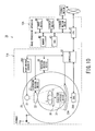
- FIG. 10 is a diagram showing a configuration example of an X-ray CT apparatus according to a second embodiment
- FIG. 11 is a diagrammatic perspective view for illustrating a configuration of an X-ray detector of the X-ray CT apparatus according to the second embodiment
- FIG. 12 is an electrical block diagram around the X-ray detector and a DAS in the X-ray CT apparatus according to the second embodiment
- FIG. 13 is a block diagram showing functions of the X-ray CT apparatus according to the second embodiment.
- FIG. 14 is a flowchart showing an operation of the X-ray CT apparatus according to the second embodiment.
- the present embodiments provide the X-Ray CT apparatus, including: an X-ray tube configured to emit X-rays; a high-voltage power supply configured to apply an X-ray tube voltage to the X-ray tube; an X-ray detector equipped with a plurality of X-ray detecting elements and configured to detect the X-rays; an image generating unit configured to generate a plurality of reference material images corresponding to respective ones of a plurality of reference materials on a basis of pre-reconstruction data of multi-energy obtained by scanning a subject; a discrimination unit configured to discriminate each of a plurality of materials contained in an imaging region of the subject on a basis of the plurality of reference material images; a monochromatic X-ray image generating unit configured to generate a monochromatic X-ray image at energy determined by each of the plurality of discriminated materials; a combined-image generating unit configured to combine a plurality of monochromatic X-ray images corresponding to the plurality of
- the present embodiments provide the image processing apparatus, including: an image generating unit configured to generate a plurality of reference material images corresponding to respective ones of a plurality of reference materials on a basis of pre-reconstruction data of multi-energy obtained by scanning a subject; a discrimination unit configured to discriminate each of a plurality of materials contained in an imaging region of the subject on a basis of the plurality of reference material images; a monochromatic X-ray image generating unit configured to generate a monochromatic X-ray image at energy determined by each of the plurality of discriminated materials; a combined-image generating unit configured to combine a plurality of monochromatic X-ray images corresponding to the plurality of materials and to generate a combined image; and a display unit configured to display the combined image on a display device.
- the present embodiments provide the image processing method, including: generating a plurality of reference material images corresponding to respective ones of a plurality of reference materials on a basis of pre-reconstruction data of multi-energy, stored in a storage, obtained by scanning a subject; discriminating each of a plurality of materials contained in an imaging region of the subject on a basis of the plurality of reference material images; generating a monochromatic X-ray image at energy determined by each of the plurality of discriminated materials; combining a plurality of monochromatic X-ray images corresponding to the plurality of materials and generating a combined image; and displaying the combined image on a display device.
- the X-ray CT apparatus, an image processing apparatus and an image processing method according to the embodiments of the present invention eliminates the need to select one of conceivable candidate energies even if optimum energy for diagnostic imaging varies with a subject's diagnosis region, materials, and the like. Also, the X-ray CT apparatus, an image processing apparatus, and an image processing method according to the embodiments of the present invention can provide images with reduced artifacts and with contrast improved on a material by material basis even if the optimum energy for diagnostic imaging varies with a subject's diagnosis region, materials, and the like.
- the X-ray CT apparatus may be any of various types, including a rotate/rotate type in which an X-ray tube and detector rotate as a single unit around the subject and a stationary/rotate type in which a large number of detecting elements are arranged to form a ring and only an X-ray tube rotates around the subject.
- a rotate/rotate type in which an X-ray tube and detector rotate as a single unit around the subject
- a stationary/rotate type in which a large number of detecting elements are arranged to form a ring and only an X-ray tube rotates around the subject.
- An X-ray CT apparatus which is an example of the X-ray CT apparatuses according to the embodiments of the present invention uses dual energy scanning which is a technique for acquiring images by scanning a subject using plural different types of X-ray tube voltage. Radiographic methods by the dual energy scanning is broadly divided into at least three methods.
- a first method is a “Slow-kV switching method” (double rotation method) which involves taking a radiograph at a first X-ray tube voltage and then taking a radiograph at a second X-ray tube voltage different from the first X-ray tube voltage, using a single X-ray tube.
- a second method is a “Fast-kV switching method” (high-speed switching method) which involves taking radiographs by rapidly switching the X-ray tube voltage of the X-ray tube on a view by view basis during rotation (scanning).
- a data acquisition system acquires data in synchronization with the switching of the X-ray tube voltage, acquiring the data at different X-ray tube voltages in a single scan.
- a third method is a “dual source system (dual lamp system)” which involves taking radiographs at different X-ray tube voltages using two X-ray tubes rather than a single X-ray tube.
- a fourth method is a “multilayer system” which uses X-ray detectors of multilayered structure.
- X-ray detectors detector in a shallow layer and detector in a deep layer
- low-energy X-rays are detected by the detector in the shallow layer
- high-energy X-rays passing through the shallow layer is detected by the detector in the deep layer.
- the present invention is applicable to any of the types. In the description of the embodiments of the present invention, it is assumed that the second method is used.
- the X-ray CT apparatus will be described citing a case in which pre-reconstruction data (raw data or projection data) of dual energy is acquired using dual energy scanning, but the present invention is also applicable to a case in which pre-reconstruction data of multi-energy is acquired using multi-energy scanning higher than the dual energy scan.
- an X-ray CT apparatus as one of the X-ray CT apparatus according to the embodiments of the present invention will be described citing a case in which pre-reconstruction data of dual energy is acquired using single energy scanning, but the present invention is also applicable to a case in which pre-reconstruction data of multi-energy is acquired using single energy scanning.
- FIG. 1 is a diagram showing a configuration example of an X-ray CT apparatus 1 according to a first embodiment.
- FIG. 1 shows the X-ray CT apparatus 1 according to the first embodiment which performs dual energy scanning.
- the X-ray CT apparatus 1 is mainly made up of a scanner 11 and an image processing apparatus (console) 12 .
- the scanner 11 of the X-ray CT apparatus 1 is normally installed in an examination room and used to generate X-ray transmission data on a patient O (subject).
- the image processing apparatus 12 is normally installed in a control room next to the examination room and used to generate projection data based on the transmission data and generate and display a reconstructed image.
- the scanner 11 of the X-ray CT apparatus 1 includes an X-ray tube 21 , a diaphragm 22 , an X-ray detector 23 , a DAS (data acquisition system) 24 , a rotary unit 25 , a high-voltage generator 26 , a diaphragm driving device 27 , a rotation driving device 28 , a table-top 30 , a table-top driving device 31 , and a controller 32 .
- the X-ray tube 21 generates X-rays by bombarding a metal target with an electron beam at an X-ray tube voltage supplied from the high-voltage generator 26 and directs the X-rays onto the X-ray detector 23 .
- An X-ray fan beam or X-ray cone beam is generated from the X-rays radiated from the X-ray tube 21 .
- Electric power necessary for X-ray irradiation is supplied to the X-ray tube 21 from the high-voltage generator 26 under the control of the controller 32 .
- the diaphragm 22 Being driven by the diaphragm driving device 27 , the diaphragm 22 adjusts an irradiation range of the X-rays from the X-ray tube 21 in an x-axis direction and z-axis direction (slice direction). That is, by adjusting an opening of the diaphragm 22 using the diaphragm driving device 27 , it is possible to change the X-ray irradiation range in the slice direction.
- the X-ray detector 23 is a one-dimensional array-type detector which has plural detecting elements in a channel direction and a single detecting element in a column (slice) direction.
- the X-ray detector 23 may be a two-dimensional array detector (also referred to as a multi-slice detection), which is arranged in a matrix with plural detecting elements both in the channel direction and slice direction.
- the X-ray detector 23 detects the X-rays radiated from the X-ray tube 21 and transmitted through the patient O.
- the DAS 24 acquires data in synchronization with switching of the X-ray tube voltage during dual energy scanning.
- the DAS 24 amplifies a signal of the transmission data (X-ray detection data) detected by each detecting element of the X-ray detector 23 and converts the signal into a digital signal.
- Output data of the DAS 24 is supplied to the image processing apparatus 12 via the controller 32 of the scanner 11 . Details of the DAS 24 will be described later.
- the rotary unit 25 holds the X-ray tube 21 , diaphragm 22 , X-ray detector 23 , DAS 24 , and diaphragm driving device 27 as an integral unit. With the X-ray tube 21 and X-ray detector 23 opposed to each other, the rotary unit 25 is configured to be able to rotate the X-ray tube 21 , diaphragm 22 , X-ray detector 23 , DAS 24 , and diaphragm driving device 27 as an integral unit around the patient O.
- the high-voltage generator 26 may be configured to be held by the rotary unit 25 .
- a direction parallel to a rotation center axis of the rotary unit 25 is defined as the z-axis direction
- a plane orthogonal to the z-axis direction is defined by the x-axis direction and a y-axis direction.
- the high-voltage generator 26 supplies electric power necessary for dual energy scanning to the X-ray tube 21 under the control of the controller 32 .
- FIG. 2 is a diagram showing a configuration example of the X-ray tube 21 and high-voltage generator 26 installed on the X-ray CT apparatus 1 according to the first embodiment.
- the X-ray tube 21 includes an anode 21 a and a filament (cathode) 21 b .
- the high-voltage generator 26 includes a low tube voltage setting device 26 a , a high tube voltage setting device 26 b , a timing controller 26 c , a switch 26 d , a high-voltage power supply 26 e , a threshold setting device 26 f , a comparator 26 g , and a capacitor C.
- High-kV high X-ray tube voltage
- Low-kV low X-ray tube voltage
- High-kV in dual energy scanning is defined as a “first X-ray tube voltage”
- Low-kV low X-ray tube voltage
- the low tube voltage setting device 26 a sets Low-kV while the high tube voltage setting device 26 b sets High-kV. Output of either the tube voltage setting device 26 a or 26 b can be selected.
- the output of the tube voltage setting device 26 a or 26 b is connected to the high-voltage power supply 26 e via the switch 26 d controlled by the timing controller 26 c .
- the switch 26 d is controlled by a signal “a” outputted from the timing controller 26 c .
- the low tube voltage setting device 26 a is selected when the signal “a” indicates “L” while the high tube voltage setting device 26 b is selected when the signal “a” indicates “H.”
- a positive side output of the high-voltage power supply 26 e is electrically connected to the anode 21 a of the X-ray tube 21 and grounded. Also, a negative side output of the high-voltage power supply 26 e is electrically connected to the filament 21 b of the X-ray tube 21 .
- the output of the high-voltage power supply 26 e is switched to Low-kV or High-kV (e.g., the X-ray tube voltage 80 kV or 140 kV), timed with switching in response to the signal “a”.
- the high-voltage power supply 26 e is equipped with a tube voltage detecting terminal T, which is connected to a positive side input of the comparator 26 g .
- the threshold setting device 26 f is connected to a negative side input of the comparator 26 g.
- the comparator 26 g accepts input of a signal “b” from the tube voltage detecting terminal T of the high-voltage power supply 26 e and input of a signal “c” from the threshold setting device 26 f , and outputs a signal “d” to the DAS 24 , indicating “L” when the signal “b” is larger than the signal “c” or indicating “H” when the signal “b” is equal to or smaller than the signal “c”.
- the DAS 24 determines that the data is transmission data at Low-kV
- the signal “d” indicates “H”
- the DAS 24 determines that the data is transmission data at High-kV.
- the controller 32 performs dual energy scanning by controlling switching operation of the switch 26 d via the timing controller 26 c of the high-voltage generator 26 and selects whether to cause the high-voltage power supply 26 e to output Low-kV set by the low tube voltage setting device 26 a or output High-kV set by the high tube voltage setting device 26 b .
- the switch 26 d gives a selected tube voltage setting signal to the high-voltage power supply 26 e.
- the controller 32 also sends a control signal to the DAS 24 .
- the DAS 24 recognizes whether data acquired by dual energy scanning is produced by Low-kV X-ray irradiation or High-kV X-ray irradiation.
- the diaphragm driving device 27 has a mechanism for adjusting the X-ray irradiation range in the x-axis direction and z-axis direction via the diaphragm 22 under the control of the controller 32 .
- the rotation driving device 28 has a mechanism for rotating the rotary unit 25 so as to rotate around a cavity by maintaining their positional relationship, under the control of the controller 32 .
- the table-top 30 allows the patient O to be placed thereon.
- the table-top driving device 31 has a mechanism for causing the table-top 30 to move up and down along the y-axis direction and move forward and backward along the z-axis direction, under the control of the controller 32 .
- the rotary unit 25 has an opening in a central portion and the patient O placed on the table-top 30 is inserted through the opening.
- the controller 32 includes a CPU (central processing unit), memory, and the like (none is shown). On instructions from the image processing apparatus 12 , the controller 32 controls the X-ray detector 23 , DAS 24 , high-voltage generator 26 , diaphragm driving device 27 , rotation driving device 28 , table-top driving device 31 , and the like so as to perform dual energy scanning.
- the image processing apparatus 12 of the X-ray CT apparatus 1 is configured based on a computer and is capable of intercommunicating with a network (local area network) N.
- the image processing apparatus 12 is mainly made up of basic hardware, including a CPU 41 , a memory 42 , an HDD (hard disc drive) 43 , an input device 44 , and a display device 45 .
- the CPU 41 is interconnected with each hardware component of the image processing apparatus 12 via a bus serving as a common signal transmission path. Note that the image processing apparatus 12 may sometimes be equipped with a storage media drive 46 .
- the CPU 41 is a control apparatus configured as an integrated circuit (LSI) in which an electronic circuit made up of semiconductors are enclosed in a package having plural terminals.
- LSI integrated circuit
- the CPU 41 executes a program stored in the memory 42 .
- the CPU 41 executes a program stored in the HDD 43 , a program installed on the HDD 43 by being transferred from the network N, or a program installed on the HDD 43 by being read out of an recording medium mounted in the storage media drive 46 , where the program is executed by being loaded into the memory 42 .
- the memory 42 is a storage device including a ROM (read only memory), a RAM (random access memory), and the like.
- the memory 42 stores IPL (initial program loading), BIOS (basic input/output system), and data, and is used as a work memory for the CPU 41 or used to temporarily store data.
- the HDD 43 is a storage device configured with an unremovable built-in metal disk to which magnetic material has been applied by coating or vapor deposition.
- the HDD 43 is a storage device adapted to store data as well as programs installed on the image processing apparatus 12 , where the programs include application programs, an OS (operating system), and the like.
- the OS may provide GUI (graphical user interface) which uses a lot of graphics in displaying information on the display device 45 for an operator such as a surgeon and allows basic actions to be performed via the input device 44 .
- the input device 44 is a pointing device configured to be operated by the operator and send an input signal to the CPU 41 according to an operator action.
- the display device 45 includes an image composition circuit, a VRAM (video random access memory), a display, and the like (none is shown).
- the image composition circuit generates composite data by combining image data with character data of various parameters.
- the VRAM presents composite data on the display.
- the display is a liquid crystal display, CRT (cathode ray tube), or the like, which displays images one after another.
- FIG. 3 is a diagram showing a configuration example of the DAS 24 installed on the X-ray CT apparatus 1 according to the first embodiment.
- the DAS 24 includes a gain storage circuit 24 a , a gain control circuit 24 b , a QV conversion circuit (integrating circuit and gain variable amplifier circuit) 24 c , an A/D conversion circuit 24 d , a calibration data storage circuit 24 e , and a calibration data application circuit 24 f .
- each X-ray detecting element of the X-ray detector 23 has the circuits 24 a to 24 f , but each X-ray detecting element group made up of plural X-ray detecting elements may be provided with the circuits 24 a to 24 f.
- the gain storage circuit 24 a prestores gains (amplification factors).
- the gain storage circuit 24 a prestores a gain corresponding to a size of the head for head radiography, a gain corresponding to a size of the chest for chest radiography, and a gain corresponding to a size of the stomach for stomach radiography.
- the gain storage circuit 24 a may also store gains in such a way as to allow images of plural regions differing in body diameter to be acquired by a single X-ray irradiation.
- the gain control circuit 24 b controls the QV conversion circuit 24 c so as to set a gain stored in the gain storage circuit 24 a.
- the QV conversion circuit 24 c In synchronization with an X-ray irradiation period, the QV conversion circuit 24 c periodically integrates a voltage signal outputted from an X-ray detecting element E m, n in an nth column on an mth channel of the X-ray detector 23 . Also, the QV conversion circuit 24 c includes an operational amplifier A, three capacitors C (C 1 , C 2 , and C 3 ) differing in capacitance, and three switches S (S 1 , S 2 , and S 3 ). The switches S 1 , S 2 , and S 3 are associated with the capacitors C 1 , C 2 , and C 3 , respectively, and on-off controlled by the gain control circuit 24 b .
- the QV conversion circuit 24 c can set six gains using combinations of ONs and OFFS of the capacitors C 1 , C 2 , and C 3 . Note that to set six gains, the QV conversion circuit 24 c may be equipped with six capacitors C equal in capacitance. Also, the number of capacitors C included in the QV conversion circuit 24 c is not limited to three and six.
- the QV conversion circuit 24 c amplifies transmission data outputted by the X-ray detecting element E m, n .
- the A/D conversion circuit 24 d converts analog data outputted by the QV conversion circuit 24 c into digital data.
- the calibration data storage circuit 24 e stores correct calibration data obtained beforehand as data for calibration through dual energy scanning under the control of the controller 32 .
- the calibration data stored in the calibration data storage circuit 24 e will be described.
- the calibration data application circuit 24 f applies calibration data stored in the calibration data storage circuit 24 e to output data of the A/D conversion circuit 24 d produced as a result of the dual energy scanning.
- the calibration data application circuit 24 f recognizes an X-ray tube voltage pair of data acquired through the dual energy scanning as well as values of X-ray tube current in a tube current modulation.
- the calibration data application circuit 24 f acquires calibration data corresponding to the recognized X-ray tube voltage pair and tube current values from the calibration data storage circuit 24 e and applies the acquired calibration data to an output signal of the A/D conversion circuit 24 d.
- the calibration data application circuit 24 f interpolates a piece of calibration data related to non-existent value of the tube current and thereby applies an interpolated piece of calibration data.
- the image processing apparatus 12 applies a logarithmic conversion process or a correction process (pre-processing) such as sensitivity correction to raw data of dual energy received from the DAS 24 of the scanner 11 , thereby generates projection data, and stores the projection data in a storage device such as the HDD 43 . Also, the image processing apparatus 12 removes scattered radiation from the pre-processed projection data. The image processing apparatus 12 removes the scattered radiation on the basis of values of the projection data in an X-ray exposure range, and makes scattered radiation correction by subtracting the scattered radiation estimated from magnitude of value of projection data to be subjected to scattered radiation correction or adjacent projection data from the projection data to be corrected. The image processing apparatus 12 generates image data based on the corrected projection data and stores the image data in a storage device such as the HDD 43 or displays the image data on the display device 45 .
- pre-processing such as sensitivity correction
- FIG. 4 is a block diagram showing functions of the X-ray CT apparatus 1 according to the first embodiment.
- the X-ray CT apparatus 1 functions as a tube voltage control unit 51 and an arbitrary energy image generating unit 52 as shown in FIG. 4 .
- the tube voltage control unit 51 includes a condition setting unit 61 and a filament current value calculation unit 62 .
- the arbitrary energy image generating unit 52 includes a projection data reading unit 71 , a separation unit 72 , a reconstruction unit 73 , a materials discrimination unit 74 , an energy setting unit 75 , a monochromatic X-ray image generating unit 76 , and a fusion image generating unit 77 .
- all or part of the tube voltage control unit 51 and arbitrary energy image generating unit 52 of the image processing apparatus 12 may be provided as hardware on the image processing apparatus 12 . Also, all or part of the tube voltage control unit 51 and arbitrary energy image generating unit 52 of the image processing apparatus 12 may be provided not only on the image processing apparatus 12 , but also on the high-voltage generator 26 and controller 32 .
- the tube voltage control unit 51 generates a tube voltage control signal intended to switch the tube voltage generated by the high-voltage generator 26 and control switching conditions and supplies the generated tube voltage control signal to the controller 32 .
- the condition setting unit 61 of the tube voltage control unit 51 has a function to set a tube current condition (maximum tube current value during modulation) based on a scan plan, information obtained from a positioning image (scout image) prior to a scan, or X-ray transmission data transmitted through the subject during scanning. Also, the condition setting unit 61 has a function to set a condition for modulating a dose of X-ray radiation in time series on the basis of a scan plan, information obtained from a scout image, or X-ray transmission data transmitted through the subject during scanning.
- modulation examples include periodic modulation with respect to a rotation angle (rotation angle modulation), modulation in the z-axis direction (z-axis modulation), periodic modulation in synchronization with an electrocardiograph signal (electrocardiograph-synchronized modulation), modulation intended to reduce radiation exposure of hypersensitive regions such as the eyeballs and ovary (hypersensitive region modulation), and combinations thereof.
- the tube current condition and modulation condition set by the condition setting unit 61 are sent to the filament current value calculation unit 62 .
- the filament current value calculation unit 62 has a function to calculate a filament current value of the X-ray tube 21 via the controller 32 and high-voltage generator 26 on the basis of the tube current condition and modulation condition set by the condition setting unit 61 . Also, the filament current value calculation unit 62 has a function to supply the calculated filament current value to a filament of the X-ray tube 21 .
- the arbitrary energy image generating unit 52 generates an arbitrary energy image for each material existing in radiographic coverage using an appropriate energy.
- the X-ray CT apparatus 1 performs dual energy scanning to acquire projection data of dual energy. Examples of methods for dual energy scanning include a “Fast-kV switching method” (method switching method) which involves taking radiographs by rapidly switching the X-ray tube voltage of the X-ray tube on a view by view basis during rotation (scanning).
- the projection data reading unit 71 of the arbitrary energy image generating unit 52 reads the projection data of dual energy as pre-reconstruction data out of the HDD 43 of the image processing apparatus 12 .
- the projection data reading unit 71 supplies the projection data of dual energy which has been read out to the separation unit 72 .
- the projection data reading unit 71 may read raw data as pre-reconstruction data instead of the projection data.
- the separation unit 72 separates (discriminates) a plurality of predetermined reference materials (contrast medium, CaCo 3 , uric acid, fat, and the like) existing in the radiographic coverage using the projection data of dual energy obtained from the projection data reading unit 71 .
- predetermined reference materials contrast medium, CaCo 3 , uric acid, fat, and the like
- the separation unit 72 separates two reference materials and generates two sets of projection data corresponding to the respective reference materials, but the number of reference materials is not limited to two as long as the number is two or more.
- the separation unit 72 supplies the two sets of projection data corresponding to the respective ones of the two separated reference materials to the reconstruction unit 73 .
- a method used by the separation unit 72 to separate reference materials will be described in detail later with reference to a flowchart of FIG. 5 .
- the reconstruction unit 73 reconstructs a reference material image (reference material weighted image) as image data for each reference material on the basis of the two sets of projection data corresponding to the respective ones of the two reference materials separated by the separation unit 72 .
- the reconstruction unit 73 generates a reference material image of reference material 1 based on the set of projection data corresponding to reference material 1 and generates a reference material image of reference material 2 based on the set of projection data corresponding to reference material 2 .
- the reconstruction unit 73 supplies the two generated reference material images corresponding to the respective ones of the two reference materials to the materials discrimination unit 74 and monochromatic X-ray image generating unit 76 .
- the materials discrimination unit 74 discriminates (identifies) materials (including tissue, contrast medium, bone, and the like) existing in the radiographic coverage and supplies results of the discrimination to the energy setting unit 75 .
- a method used by the materials discrimination unit 74 to discriminate materials will be described in detail later with reference to a flowchart of FIG. 5 .
- the energy setting unit 75 sets an energy at which a monochromatic X-ray image for each material existing in the radiographic coverage will be generated.
- the energy setting unit 75 supplies data on the set energy to the monochromatic X-ray image generating unit 76 .
- the monochromatic X-ray image generating unit 76 On the basis of the energy set for each material by the energy setting unit 75 and the two reference material images generated by the reconstruction unit 73 for the respective ones of the two reference materials, the monochromatic X-ray image generating unit 76 generates a monochromatic X-ray image for each material existing in the radiographic coverage.
- the term “monochromatic X-ray image” used in the first embodiment means an image which is created based on the projection data obtained by taking a radiograph using continuous spectrum X-rays with specific effective X-ray energy and which is equivalent to an image obtained by taking a radiograph using monochromatic X-rays of a specific energy.
- the monochromatic X-ray image generating unit 76 supplies data on the generated monochromatic X-ray image to the fusion image generating unit 77 .
- the fusion image generating unit 77 generates a fusion image using the monochromatic X-ray image generated by the monochromatic X-ray image generating unit 76 .
- FIG. 5 is a flowchart showing an operation of the X-ray CT apparatus 1 according to the first embodiment.
- step S 1 the scanner 11 of the X-ray CT apparatus 1 performs dual energy scanning under the control of the controller 32 , and acquires projection data via the dual energy scanning (e.g., a Fast-kV switching method (high speed switching method)). Specifically, the scanner 11 takes radiographs by rapidly switching the X-ray tube voltage of the X-ray tube on a view by view basis during rotation (scanning) and radiographs the subject O using two different types of X-ray tube voltage: High-kV (high X-ray tube voltage) and Low-kV (low X-ray tube voltage). Note that the X-ray CT apparatus 1 can use a multi-energy scan higher than the dual energy scan. For example, in the case of triple energy scanning, the subject O is radiographed using three different types of X-ray tube voltage.
- a Fast-kV switching method high speed switching method
- step S 2 the DAS 24 of the scanner 11 acquires data in synchronization with switching of the X-ray tube voltage during dual energy scanning and amplifies a signal of the transmission data detected by each detecting element of the X-ray detector 23 and converts the signal into a digital signal.
- Output data of the DAS 24 is supplied to the image processing apparatus 12 via the controller 32 of the scanner 11 .
- the CPU 41 of the image processing apparatus 12 of the X-ray CT apparatus 1 acquires raw data of dual energy inputted by the DAS 24 of the scanner 11 , applies a logarithmic conversion process or a correction process (pre-processing) such as sensitivity correction to the acquired raw data, thereby generates projection data, and stores the projection data in a storage device such as the HDD 43 . Under the control of the CPU 41 , the HDD 43 stores the projection data of dual energy.
- step S 3 the projection data reading unit 71 of the arbitrary energy image generating unit 52 of the CPU 41 reads the projection data of dual energy stored in the HDD 43 of the image processing apparatus 12 .
- the projection data reading unit 71 supplies the projection data which has been read out to the separation unit 72 .
- step S 4 the separation unit 72 separates the two reference materials existing in the radiographic coverage using the projection data of dual energy from the projection data reading unit 71 .
- the separation unit 72 supplies the two sets of projection data corresponding to the respective ones of the two separated reference materials to the reconstruction unit 73 .
- the reconstruction unit 73 reconstructs a reference material image (reference material weighted image) as image data for each reference material on the basis of the two sets of projection data corresponding to the respective ones of the two reference materials separated by the separation unit 72 .
- the reconstruction unit 73 generates a reference material image of the first reference material on the basis of the set of projection data corresponding to the first reference material and generates a reference material image of the second reference material on the basis of the set of projection data corresponding to the second reference material.
- the reconstruction unit 73 supplies the two generated reference material images corresponding to the respective ones of the two reference materials to the materials discrimination unit 74 and monochromatic X-ray image generating unit 76 .
- step S 6 using the two reference material images generated by the reconstruction unit 73 for the respective ones of the two reference materials, the materials discrimination unit 74 discriminates the materials existing in the radiographic coverage.
- Non-Patent Document Johnson TR. Et al., “Material differentiation by dual energy CT: initial experience”, Eur Radiol (2007), 17, 1510-1517) and a raw-data-based method which separates the projection data of dual energy into two reference materials, creates images based on the respective reference materials, and thereby identifies materials using the created images
- Patent Document Japanese Patent Application Publication (Laid-open: KOKAI) No. 2009-261942 A).
- the present invention is applicable to both methods, but it is assumed that the latter method is used in the first embodiment. Of course, a method other than those described above may be used as long as the method can identify materials.
- the separation unit 72 separates the projection data of dual energy on the basis of the two reference materials.
- a separation method using the two reference materials is described in Patent Document 1 described above. For example, assuming any given material made up of two reference materials, suppose an X-ray attenuation coefficient (E, x, y) acquired for the given material is to be expressed by a sum of X-ray attenuation coefficients (linear attenuation coefficients) of the two reference materials.
- the X-ray attenuation coefficient ⁇ (E, x, y) acquired for the given material is expressed by the sum (linear combination) of the X-ray attenuation coefficients (linear attenuation coefficients) of the two reference materials using a mathematical expression, and it is not assumed that the given material is actually made up of the two reference materials in a physical sense.
- This method allows the X-ray attenuation coefficient ⁇ (E, x, y) of any material to be separated into the sum of the X-ray attenuation coefficients (linear attenuation coefficients) of the two reference materials.
- the reconstruction unit 73 reconstructs the projection data separated in this way and thereby generates two reconstructed images.
- c 1 (x, y) and c 2 (x, y) are derived, where c 1 (x, y) and c 2 (x, y) represent abundance ratios of reference material 1 and reference material 2 of a pixel (or voxel) at (x, y).
- c 1 (x, y) and c 2 (x, y) represent how closely the given material resembles reference material 1 and reference material 2 .
- ⁇ (E, x, y) the X-ray attenuation coefficient ⁇ (E, x, y) acquired for the given material is expressed by Eq. (1) below.
- ⁇ ( E,x,y ) ⁇ 1 ( E ) c 1 ( x,y )+ ⁇ 2 ( E ) c 2 ( x,y ) (1)
- the member “E” in Eq. (1) above represents X-ray energy.
- the members “ ⁇ 1 (E)” and “ ⁇ 2 (E)” represent the linear attenuation coefficients of reference materials 1 and 2 , respectively at energy E.
- a graph is created by plotting c 1 on a y-axis on a pixel by pixel basic or on a voxel by voxel basic, and taking c 2 on an x-axis.
- the graph is shown in FIG. 6 .
- c 1 is taken as the y-axis and c 2 is taken as the x-axis as an example in the first embodiment, conversely c 1 may be the x-axis with c 2 taken as the y-axis.
- Another coordinate system such as an oblique coordinate system may be used instead of an orthogonal coordinate system.
- the coordinate system may be rotated at a predetermined angle around an origin or the two axes may be transformed by multiplying c 1 and c 2 by a coefficient. That is, it is sufficient if a linearly combined image can represent a correlation between two reference material images, and the present invention is applicable to any diagram which expresses the correlation between c 1 and c 2 .
- FIG. 6 graphically represents a contrast medium, fat, uric acid and calcium carbonate (CaCO 3 ) which results from calcification, as reference materials by way of example.
- ⁇ X-ray attenuation coefficient
- ⁇ X-ray attenuation coefficient
- ⁇ linear attenuation coefficients
- water a contrast medium 50 [mgI/ml] and water.
- c 1 (x, y) and c 2 (x, y) can take values larger than 1 depending on the given material.
- the contrast medium 50 [mgI/ml] which is one of the reference materials
- the contrast medium 50 [mgI/ml] is expressed by the sum of the X-ray attenuation coefficients (linear attenuation coefficients) of two reference materials, namely, the contrast medium 50 [mgI/ml] and water
- the contrast medium 50 [mgI/ml] has a concentration of 100%
- the contrast medium 50 [mgI/ml] with a concentration of 100% is represented by point A.
- linear equations which represent correlations between water and fat, between water and uric acid, and between water and calcium carbonate can be determined.
- a mixture of fat and water is represented by a point on straight line 2 linking point B and point C.
- linear equations which represent correlations between water and another material are determined in the first embodiment for sake of convenience, this is not restrictive.
- a linear equation which represents a correlation with a material represented by any of points may be determined.
- the correlation lines determined above represent a mixture of respective materials with water.
- a different straight line indicates that a different material is contained in the mixture, and this allows materials to be separated.
- the point represented by c 1 (x, y) and c 2 (x, y) is located in, it is possible to determine what kind of material it is.
- a material may be discriminated using three or more reference materials. This will allow a material to be discriminated at a higher resolution.
- the latter method which uses linear attenuation coefficients, will be described.
- the linear attenuation coefficient ⁇ of each material is known.
- the values c 1 and c 2 can be acquired by substituting ⁇ 1 (E Low ), ⁇ 2 (E Low ), ⁇ 1 (E High ) and ⁇ 2 (E High ) at two different types of X-ray energy into Eq. (1) above and by solving a simultaneous equation given by Eq.
- the character “E” in Eq. (2) above is X-ray energy.
- the subscripts “Low” and “High” are low energy and high energy at two different types of X-ray energy.
- the character “ ⁇ ” is the linear attenuation coefficient of each material at X-ray energy E.
- reference materials are separated on the basis of pre-reconstruction data and materials are discriminated on the basis of reference material images, other measures may be taken as long as reference materials can be separated and materials can be discriminated.
- the materials discrimination unit 74 supplies a discrimination result of each material existing in the radiographic coverage to the energy setting unit 75 .
- step S 7 the energy setting unit 75 acquires the discrimination results from the materials discrimination unit 74 .
- the energy setting unit 75 reads out the energy table prestored in the HDD 43 or memory 42 of the image processing apparatus 12 .
- FIG. 7 is a diagram showing a configuration example of the energy table prestored in the HDD 43 or memory 42 of the image processing apparatus 12 .
- materials and the energies required to generate monochromatic X-ray images for the materials are stored by being associated with each other.
- Material A is stored by being associated with 75 [keV] as the energy required to generate a monochromatic X-ray image for Material A.
- Bone is stored by being associated with 130 [keV] as the energy required to generate a monochromatic X-ray image for artifacts.
- Artifact is stored by being associated with 130 [keV] as the energy required to generate a monochromatic X-ray image for the artifact.
- materials need not be composed of only an arbitrary material, and an energy may be associated with a mixture of two materials or associated with one material.
- the energies stored in the energy table by being associated with materials are, so to say, appropriate energies for the materials and in determining the appropriate energies as referred to herein, various factors are taken into consideration, including, for example, ease of providing clear contrast due to large differences in CT value and capability to remove bones and artifacts.
- the energy setting unit 75 sets energy at which a monochromatic X-ray image for each material existing in the radiographic coverage will be generated. Note that as the energy is set here for each material at a high resolution, a monochromatic X-ray image can be created at a high resolution subsequently in a process of step S 8 .
- the energy setting unit 75 supplies data on the set energy to the monochromatic X-ray image generating unit 76 .
- step S 8 the monochromatic X-ray image generating unit 76 generates a monochromatic X-ray image for each material existing in the radiographic coverage on the basis of the energy set by the energy setting unit 75 for each material and the two reference material images generated by the reconstruction unit 73 .
- the monochromatic X-ray CT image is defined by Eq. (3) below.
- CT ⁇ ⁇ number ⁇ ( E , x , y ) 1000 ⁇ ⁇ ⁇ ( E , x , y ) - ⁇ water ⁇ ( E , x , y ) ⁇ water ⁇ ( E , x , y ) ( 3 )
- the member “ ⁇ water (E, x, y)” in Eq. (3) above is the linear attenuation coefficient of water.
- the member “ ⁇ (E, x, y)” is the X-ray attenuation coefficient acquired for the material and is given by Eq. (1) above.
- the linear attenuation coefficient ⁇ (E, x, y) at an arbitrary energy is found from Eq. (1) above and a monochromatic X-ray image at the arbitrary energy can be acquired by substituting the linear attenuation coefficient into Eq. (3) above.
- a monochromatic X-ray image is generated for each material at the arbitrary energy.
- the monochromatic X-ray image generating unit 76 supplies data on the generated monochromatic X-ray image to the fusion image generating unit 77 .
- the monochromatic X-ray image generating unit 76 may generate a monochromatic X-ray image for each material at an arbitrary energy that a user specifies via a user input device 44 .
- step S 9 the fusion image generating unit 77 generates a fusion (combined) image based on the monochromatic X-ray images generated by the monochromatic X-ray image generating unit 76 .
- the fusion image generating unit 77 fuses (superimposes or combines) the monochromatic X-ray images for respective materials and generates a fusion image (combined image).
- FIGS. 8 and 9 are diagrams for illustrating a concept of generating a fusion image.
- the energy (optimum energy) set for Soft Tissue 1 is 80 [keV]
- the energy (optimum energy) set for Soft Tissue 2 is 50 [keV]
- the energy (optimum energy) set for Soft Tissue 3 is 50 [keV].
- the energy set for Bone is 130 [keV] and that the energy set for Artifact is 130 [keV]. In this case, as shown in FIG.
- a monochromatic X-ray image is generated (created) for Soft Tissue 1 at an energy of 80 [keV]
- monochromatic X-ray images are generated for Soft Tissues 2 and 3 at an energy of 50 [keV]
- monochromatic X-ray images are generated for Bone and Artifact at an energy of 130 [keV].
- the three monochromatic X-ray images generated for Soft Tissue's 1 to 3, Bone, and Artifact are fused (combined) to generate a fusion image.
- the fusion image generating unit 77 may apply a weighted addition process or weighted subtraction process to specific images among the monochromatic X-ray images for respective materials using desired coefficients. This will make it possible to highlight a specific monochromatic X-ray image instead of integrating the monochromatic X-ray images for respective materials uniformly in equal proportions.
- the fusion image generating unit 77 supplies the generated fusion image to the display device 45 .
- the CPU 41 controls the display device 45 so as to display the generated fusion image. Any of 2D display (two-dimensional display) and 3D display (three-dimensional display) may be used for the fusion image.
- the CPU 41 may display each monochromatic X-ray image as it is on the display device 45 rather than integrating the monochromatic X-ray images for respective materials. In so doing, the CPU 41 may display each monochromatic X-ray image in colors on the display device 45 using different colors or display the monochromatic X-ray image in 2D display mode or 3D display (three-dimensional display) mode. Also, a single monochromatic X-ray image may be multiplied by weighting coefficients to display a weighted image or suppressed image.
- the energy required to generate a monochromatic X-ray image varies from material to material, it is conceivable that the CT values displayed on the display device 45 may vary as well. Thus, the energy may be varied among materials only for image display as described above, by fixing the CT values displayed on the display device 45 at a specific energy.
- the X-ray CT apparatus 1 when performing the fusion image display process, the X-ray CT apparatus 1 according to the first embodiment generates projection data by performing dual energy scanning or multi-energy scanning.
- the present invention is applicable not only to such cases, but also to when projection data generated by dual energy scanning or multi-energy scanning performed beforehand is stored in the HDD 43 .
- the X-ray CT apparatus 1 according to the first embodiment can create an image at an arbitrary energy for each material based on pre-reconstruction data of multi-energy and then create and display a singe fusion image. Consequently, the X-ray CT apparatus 1 according to the first embodiment eliminates the need to select one of conceivable candidate energies even if optimum energy for diagnostic imaging varies with a subject's diagnosis region, materials, and the like. Also, the X-ray CT apparatus 1 according to the first embodiment can provide images with reduced artifacts and with contrast improved on a material by material basis even if the optimum energy for diagnostic imaging varies with a subject's diagnosis region, materials, and the like.
- the X-ray CT apparatus 1 is configured to perform dual energy scanning to obtain projection data of multi-energy.
- a variation of the X-ray CT apparatus 1 is designed to obtain projection data of multi-energy by performing a single energy scan in a “multilayer system” which uses X-ray detectors of a multilayered structure.
- the X-ray detector 23 (illustrated in FIG. 1 ) has a multilayered structure, for example, a two-layer structure (a detector in a shallow layer and a detector in a deep layer). In that case, low-energy X-rays are detected by the detector in the shallow layer and high-energy X-rays passing through the shallow layer is detected by the detector in the deep layer.
- the projection data reading unit 71 (illustrated in FIG. 4 ) reads the projection data of dual energy out of the HDD 43 of the image processing apparatus 12 , the dual energy being obtained from each layer of the two-layer structure. Note that the operation of the separation unit 72 (illustrated in FIG. 4 ) and subsequent components of the X-ray CT apparatus 1 are also applicable to the variation of the X-ray CT apparatus 1 .
- An X-ray CT apparatus is a photon counting X-ray CT apparatus.
- FIG. 10 is a diagram showing a configuration example of the X-ray CT apparatus according to the second embodiment.
- FIG. 10 shows the X-ray CT apparatus 1 A according to the second embodiment.
- the X-ray CT apparatus 1 A is mainly made up of a scanner 11 A and an image processing apparatus (console) 12 A.
- the scanner 11 A of the X-ray CT apparatus 1 A is normally installed in an examination room and used to generate X-ray transmission data on a patient O (subject).
- the image processing apparatus 12 A is normally installed in a control room next to the examination room and used to generate projection data based on the transmission data and generate and display a reconstructed image.
- the scanner 11 A of the X-ray CT apparatus 1 A includes an X-ray tube 21 , an diaphragm 22 , an X-ray detector (photon counting image detector) 23 A, a DAS 24 A, a rotary unit 25 , a high-voltage generator 26 A, an diaphragm driving device 27 , a rotation driving device 28 , a table-top 30 , a table-top driving device 31 , and a controller 32 .
- the X-ray detector 23 A is arranged in a matrix with plural channels in a channel direction and plural columns of pixels in a slice direction. Moreover, the X-ray detector 23 A is curved in the channel direction, especially by considering a divergence angle of an X-ray beam from the X-ray tube 21 . Note that an overall shape of the X-ray detector 23 A depends on its application, and may be planar. A semiconductor detector will be described below as an example, but the present invention is applicable not only to semiconductor detectors, but also to any type of detector capable of photon calculation.
- FIG. 11 is a diagrammatic perspective view for illustrating a configuration of the X-ray detector 23 A of the X-ray CT apparatus 1 A according to the second embodiment.
- the X-ray detector 23 A is divided into plural detector blocks 23 a , which are able to be detachably coupled.
- a radiolucent image from the X-ray tube 21 is designed to be obtained by a collimator (not shown) placed in front of the detector blocks 23 a on the X-ray incidence side, the collimator being made of molybdenum or tungsten.
- Each detector block 23 a is constructed from a compound semiconductor and provided with a monolithic structure made up of a layered semiconductor cell S of a predetermined size (e.g., a few centimeters by a few centimeters), an electrically charged electrode E 1 for voltage application, and plural collecting electrodes E 2 arranged in a two-dimensional array (on a grid), where the electrically charged electrode E 1 covers a radiation incidence surface of the semiconductor cell S while the collecting electrodes E 2 divide and cover a surface of the semiconductor cell S opposite the radiation incidence surface.
- the collecting electrodes E 2 correspond to individual pixels.
- Materials available for the semiconductor cell S include a cadmium telluride semiconductor (CdTe semiconductor), cadmium zinc telluride semiconductor (CdZnTe semiconductor), and silicon semiconductor (Si semiconductor).
- CdTe semiconductor cadmium telluride semiconductor
- CdZnTe semiconductor cadmium zinc telluride semiconductor
- Si semiconductor silicon semiconductor
- a size of each pixel with respect to X-rays depends on a size of each of the plural collecting electrodes E 2 resulting from division into a grid. The size is small enough to allow X-rays to be detected as photons (particles). As a result, the X-ray detector 23 A is configured to be able to count photons and a predetermined number of pixel channels are formed in a matrix on the entire X-ray detector 23 A.
- the X-rays transmitted through the patient O are counted as X-ray particles (i.e., X-ray photons) by the X-ray detector 23 A at fixed time intervals and a detection signal of an analog amount corresponding to photon energy is outputted from each pixel P (each of pixels P 1 to Pk).
- the detection signal of each pixel outputted from the X-ray detector 23 A is sent to the DAS 24 A.
- FIG. 12 is an electrical block diagram around the X-ray detector 23 A and DAS 24 A in the X-ray CT apparatus 1 A according to the second embodiment.
- each pixel P of the X-ray detector 23 A includes a semiconductor cell S, which is controlled by the controller 32 .
- the DAS 24 A includes a processing circuit C for each pixel P, where the processing circuit C is controlled by the controller 32 .
- the processing circuit C includes a charge amplifier 81 , a waveform shaping circuit 82 , comparators (Dual Discri) 83 1 to 83 n of first to nth stages (n is a positive integer), switches 84 1 to 84 n of first to nth stages, a threshold logic circuit (Discri Logic) 85 , counters (CLK) 86 1 to 86 m of first to mth stages, a weighting circuit 87 , and an adder circuit 88 .
- Discri Logic threshold logic circuit
- CLK counters
- the charge amplifier 81 is connected to each of the plural collecting electrodes E 2 of the semiconductor cell S.
- the charge amplifier 81 outputs an electric charge collected in response to incidence of X-ray particles, as a voltage pulse signal.
- An output end of the charge amplifier 81 is connected to the waveform shaping circuit 82 whose gain and offset are adjustable.
- the waveform shaping circuit 82 shapes a waveform of a detected voltage pulse signal by processing the waveform at a preset gain and offset.
- the gain and offset of the waveform shaping circuit 82 are adjustable parameters which allow for nonuniformity of charging characteristics among pixels of the semiconductor cell S.
- By adjusting the gain and offset of the waveform shaping circuit 82 of each pixel via a calibration operation in advance it is possible to perform waveform shaping by eliminating the nonuniformity described above. Consequently, the pulse signal outputted from the waveform shaping circuit 82 of each acquisition channel after waveform shaping has characteristics which substantially reflect an energy amount of incident X-ray particles, almost dissolving dispersion among the pixels.
- An output end of the waveform shaping circuit 82 is connected to a comparison input end of each of the plural comparators 83 1 to 83 n .
- Reference values TH1 (upper limit reference value THH) to THn (lower limit reference value THL) differing from one another are applied to respective input ends of the comparators 83 1 to 83 n .
- a peak value (energy of an absorbed X-ray photon) of one pulse signal from the waveform shaping circuit 82 with different reference values TH1 to THn, it is possible to separate the energy of the X-ray photon (X-ray particle) absorbed by the semiconductor cell S into one of plural energy regions set in advance. For example, when n is 3, the energy region into which the X-ray photon energy is separated varies depending on which of the reference values TH1 to TH3 the peak value of the pulse signal exceeds.
- the peak value When the peak value is between the reference values TH1 to TH2, the energy of the absorbed X-ray photon is separated so as to be included in a first energy region. When the peak value is between the reference values TH2 to TH3, the energy of the absorbed X-ray photon is separated so as to be included in a second energy region.
- the peak value is equal to or smaller than the reference value TH3 (lower limit reference value THL) or equal to or larger than the reference value TH1 (upper limit reference value THH), the X-ray photon energy is separated as not causing disturbance or white noise from semiconductor cell S and charge amplifier 81 to be detected.
- the peak value can also become equal to or larger than the reference value TH1 (upper limit reference value THH) when two or more X-ray photons are incident on the pixel, but such an event is treated similarly to disturbance and the like as not being a major signal in forming image information because of a low probability of occurrence.
- TH1 upper limit reference value THH
- the number of reference values i.e., the number of separable energy regions is not limited to 3.
- the number of reference values may be 2, 4, or the like as well.
- the switches 84 1 to 84 n are designed to turn on when the pulse signals outputted from the respective comparators 83 n to 83 n exceed the reference values TH1 to THn of the switches 84 1 to 84 n and turn off otherwise.
- the switch 84 1 turns on when the pulse signal outputted from the comparator 83 1 exceeds the reference value TH1 of the switch 84 1 , and turns off otherwise.
- Output ends of the switches 84 1 to 84 n are connected to the threshold logic circuit 85 .
- the threshold logic circuit 85 senses which of the comparators 83 1 to 83 n is on (off) and generates a clock pulse so as to count output pulses corresponding to a maximum pulse signal of the activated comparators 83 1 to 83 n .
- Plural output ends of the threshold logic circuit 85 are connected to respective ones of plural counters 86 1 to 86 m to count clock pulses.
- the plural counters 86 1 to 86 m act to count the pulses of pulse signals with wave heights appropriate for the respective counters.
- pulses larger than TH2 and smaller than TH1 are counted by the counter 86 1 and pulses larger than TH3 and smaller than TH2 are counted by the counter 86 2 (and so on).
- the number m of counters may be m ⁇ n ⁇ 1, where n is the number of comparators. This is the case when the number of pulses is counted together in plural wave height ranges instead of counting the number of pulses separated according to wave height in each wave height range.
- the counters 86 1 to 86 m count the numbers of X-ray photons entering the respective energy regions for a fixed period of time by counting up the clock pulses outputted from the threshold logic circuit 85 .
- the weighting circuit 87 assign weights to counts outputted from the respective counters 86 1 to 86 m .
- the adder circuit 88 adds together the weighted counts classified by the energy region and outputted from the weighting circuit 87 , thereby generates raw data of each pixel P, and sends the raw data to the image processing apparatus 12 A via the controller 32 .
- the adder circuit 88 generates raw data of dual energy based on plural counts from the respective energy regions as well as raw data of dual energy based on plural additional values obtained, respectively, by plural different, types of weighting.
- the DAS 24 counts the number of X-ray photons incident on each pixel P of the X-ray detector 23 A in each of the energy regions corresponding to m counter stages using the plural counters 86 1 to 86 m .
- the counts thus obtained, i.e., the counts of the X-ray photons are read out of the plural counters 86 1 to 86 m as detection data (raw data) of digital quantities. Data is read from each pixel P in an ASIC layer.
- the high-voltage generator 26 A supplies electric power necessary for X-ray irradiation to the X-ray tube 21 under the control of the controller 32 .
- the image processing apparatus 12 A of the X-ray CT apparatus 1 A is configured based on a computer and is capable of intercommunicating with a network N.
- the image processing apparatus 12 a is made up of basic hardware, including a CPU 41 , a memory 42 , an HDD 43 , an input device 44 , and a display device 45 .
- the CPU 41 is interconnected with each hardware component of the image processing apparatus 12 A via a bus serving as a common signal transmission path.
- the image processing apparatus 12 A may sometimes be equipped with a storage media drive 46 .
- the image processing apparatus 12 A applies a logarithmic conversion process or a correction process (pre-processing) such as sensitivity correction to raw data of dual energy received from the DAS 24 A of the scanner 11 A, thereby generates projection data, and stores the projection data in a storage device such as the HDD 43 . Also, as with the image processing apparatus 12 (illustrated in FIG. 1 ), the image processing apparatus 12 A removes scattered radiation from the pre-processed projection data. As with the image processing apparatus 12 (illustrated in FIG.
- the image processing apparatus 12 A removes the scattered radiation on the basis of values of the projection data in an X-ray exposure range, and makes scattered radiation correction by subtracting the scattered radiation estimated from magnitude of value of projection data to be subjected to scattered radiation correction or adjacent projection data from the projection data to be corrected. As with the image processing apparatus 12 (illustrated in FIG. 1 ), the image processing apparatus 12 A generates image data based on the corrected projection data and stores the image data in a storage device such as the HDD 43 or displays the image data on the display device 45 .
- FIG. 13 is a block diagram showing functions of the X-ray CT apparatus 1 A according to the second embodiment.
- the X-ray CT apparatus 1 A functions as an arbitrary energy image generating unit 52 as shown in FIG. 13 .
- the arbitrary energy image generating unit 52 includes a projection data reading unit 71 , a separation unit 72 , a reconstruction unit 73 , a materials discrimination unit 74 , an energy setting unit 75 , a monochromatic X-ray image generating unit 76 , and a fusion image generating unit 77 .
- all or part of the arbitrary energy image generating unit 52 of the image processing apparatus 12 A may be provided as hardware on the image processing apparatus 12 .
- all or part of the arbitrary energy image generating unit 52 of the image processing apparatus 12 A may be provided not only on the image processing apparatus 12 A, but also on the high-voltage generator 26 A and controller 32 .
- FIG. 14 is a flowchart showing an operation of the X-ray CT apparatus 1 A according to the second embodiment.
- step S 11 the scanner 11 A of the X-ray CT apparatus 1 A performs single energy scanning under the control of the controller 32 .
- step S 12 the DAS 24 A of the scanner 11 A generates raw data of dual energy based on plural counts from the respective energy regions as well as raw data of dual energy based on plural additional values obtained, respectively, by plural different types of weighting. Output data of the DAS 24 A is supplied to the image processing apparatus 12 A via the controller 32 of the scanner 11 A.
- the CPU 41 of the image processing apparatus 12 A of the X-ray CT apparatus 1 A acquires raw data of dual energy inputted by the DAS 24 A of the scanner 11 A, applies a logarithmic conversion process or a correction process (pre-processing) such as sensitivity correction to the acquired raw data, thereby generates projection data of dual energy, and stores the projection data in a storage device such as the HDD 43 . Under the control of the CPU 41 , the HDD 43 stores projection data of dual energy.
- the X-ray CT apparatus 1 A when performing the fusion image display process, the X-ray CT apparatus 1 A according to the second embodiment generates projection data by performing single energy scanning.
- the present invention is applicable not only to such cases, but also to when projection data generated by single energy scanning performed beforehand is stored in the HDD 43 .
- the X-ray CT apparatus 1 A according to the second embodiment can create an image at an arbitrary energy for each material on the basis of pre-reconstruction data of dual energy and then create and display a single fusion image. Consequently, the X-ray CT apparatus 1 A according to the second embodiment eliminates the need to select one of conceivable candidate energies even if optimum energy for diagnostic imaging varies with a subject's diagnosis region, materials, and the like. Also, the X-ray CT apparatus 1 A according to the second embodiment can provide images with reduced artifacts and with contrast improved on a material by material basis even if the optimum energy for diagnostic imaging varies with a subject's diagnosis region, materials, and the like.
Abstract
Description
μ(E,x,y)=μ1(E)c 1(x,y)+μ2(E)c 2(x,y) (1)
μ(E Low)=μ1(E Low)c 1+μ2(E Low)c 2
μ(E High)=μ1(E High)c 1+μ2(E High)c 2 (2)
Claims (15)
Applications Claiming Priority (5)
| Application Number | Priority Date | Filing Date | Title |
|---|---|---|---|
| JP2012-189917 | 2012-08-30 | ||
| JP2012189917 | 2012-08-30 | ||
| JP2013179627A JP6261915B2 (en) | 2012-08-30 | 2013-08-30 | X-ray CT apparatus, image processing apparatus, and image processing method |
| JP2013-179627 | 2013-08-30 | ||
| PCT/JP2013/073405 WO2014034888A1 (en) | 2012-08-30 | 2013-08-30 | X-ray ct apparatus, image processing apparatus, and image processing method |
Related Parent Applications (1)
| Application Number | Title | Priority Date | Filing Date |
|---|---|---|---|
| PCT/JP2013/073405 Continuation WO2014034888A1 (en) | 2012-08-30 | 2013-08-30 | X-ray ct apparatus, image processing apparatus, and image processing method |
Publications (2)
| Publication Number | Publication Date |
|---|---|
| US20140321603A1 US20140321603A1 (en) | 2014-10-30 |
| US9532759B2 true US9532759B2 (en) | 2017-01-03 |
Family
ID=50183691
Family Applications (1)
| Application Number | Title | Priority Date | Filing Date |
|---|---|---|---|
| US14/326,889 Active US9532759B2 (en) | 2012-08-30 | 2014-07-09 | X-ray CT apparatus, image processing apparatus, and image processing method |
Country Status (4)
| Country | Link |
|---|---|
| US (1) | US9532759B2 (en) |
| JP (1) | JP6261915B2 (en) |
| CN (1) | CN104105445B (en) |
| WO (1) | WO2014034888A1 (en) |
Cited By (17)
| Publication number | Priority date | Publication date | Assignee | Title |
|---|---|---|---|---|
| US20140185765A1 (en) * | 2012-12-27 | 2014-07-03 | Samsung Electronics Co., Ltd. | X-ray detection panel, x-ray imaging apparatus, and x-ray image generation method |
| US20150282778A1 (en) * | 2012-12-27 | 2015-10-08 | Kabushiki Kaisha Toshiba | X-ray ct apparatus and controlling method |
| US20160022237A1 (en) * | 2013-05-23 | 2016-01-28 | Kabushiki Kaisha Toshiba | X-ray ct apparatus |
| US20160022243A1 (en) * | 2013-04-04 | 2016-01-28 | Kabushiki Kaisha Toshiba | X-ray computed tomography apparatus |
| US20160054453A1 (en) * | 2014-08-22 | 2016-02-25 | Kabushiki Kaisha Toshiba | Photon counting x-ray ct apparatus |
| US20160066876A1 (en) * | 2013-05-28 | 2016-03-10 | Kabushiki Kaisha Toshiba | X-ray ct apparatus and x-ray detector |
| US20160091438A1 (en) * | 2014-09-26 | 2016-03-31 | Samsung Electronics Co., Ltd. | X-ray apparatus and method of controlling the same |
| US20160095564A1 (en) * | 2014-10-01 | 2016-04-07 | Kabushiki Kaisha Toshiba | X-ray ct apparatus, image processing apparatus, and image processing method |
| US20160157799A1 (en) * | 2014-12-05 | 2016-06-09 | Samsung Electronics Co., Ltd. | Computed tomographic apparatus and method for controlling the same |
| US20170086775A1 (en) * | 2015-09-30 | 2017-03-30 | General Electric Company | Systems and methods for dual-energy computed tomography imaging |
| US20190000409A1 (en) * | 2017-06-28 | 2019-01-03 | Canon Medical Systems Corporation | X-ray ct apparatus |
| US20190154852A1 (en) * | 2017-11-16 | 2019-05-23 | NueVue Solutions, Inc. | Analog Direct Digital X-Ray Photon Counting Detector For Resolving Photon Energy In Spectral X-Ray CT |
| US10429323B2 (en) * | 2015-07-24 | 2019-10-01 | Photo Diagnostic Systems, Inc. | Method and apparatus for performing multi-energy (including dual energy) computed tomography (CT) imaging |
| US10573030B2 (en) | 2017-04-07 | 2020-02-25 | Photo Diagnostic Systems, Inc. | Method for artifact reduction using monoenergetic data in computed tomography |
| US20200155110A1 (en) * | 2018-11-16 | 2020-05-21 | Varex Imaging Corporation | Imaging system with energy sensing and method for operation |
| US20210236078A1 (en) * | 2018-11-09 | 2021-08-05 | Canon Kabushiki Kaisha | Information processing apparatus and method, and radiography system |
| US11813095B2 (en) | 2018-06-27 | 2023-11-14 | Canon Kabushiki Kaisha | Radiation imaging apparatus, radiation imaging method, and non-transitory computer-readable storage medium |
Families Citing this family (26)
| Publication number | Priority date | Publication date | Assignee | Title |
|---|---|---|---|---|
| US20140125352A1 (en) * | 2011-07-05 | 2014-05-08 | Nokia Corporation | Apparatus, system, method and computer program for testing an electrical connection |
| KR20150043630A (en) * | 2013-10-14 | 2015-04-23 | 삼성전자주식회사 | X-ray image apparatus and control method for the same |
| US20150264789A1 (en) * | 2014-03-14 | 2015-09-17 | General Electric Company | Methods and systems for controlling voltage switching |
| JP6243580B2 (en) * | 2014-10-20 | 2017-12-06 | コーニンクレッカ フィリップス エヌ ヴェKoninklijke Philips N.V. | Cardiac reconstruction for photon counting CT |
| US9964499B2 (en) * | 2014-11-04 | 2018-05-08 | Toshiba Medical Systems Corporation | Method of, and apparatus for, material classification in multi-energy image data |
| JP6656891B2 (en) * | 2014-11-19 | 2020-03-04 | キヤノンメディカルシステムズ株式会社 | X-ray CT apparatus, image processing apparatus, and program |
| CN104545960B (en) * | 2014-12-18 | 2017-05-31 | 沈阳东软医疗系统有限公司 | A kind of system of selection of scanning voltage of dual intensity CT and equipment |
| US9836859B2 (en) * | 2015-01-09 | 2017-12-05 | Toshiba Medical Systems Corporation | Wide X-ray spectrum photon counting computed tomography |
| US9913622B2 (en) * | 2015-02-23 | 2018-03-13 | Toshiba Medical Systems Corporation | X-ray CT apparatus and image processing device |
| WO2017073399A1 (en) * | 2015-10-27 | 2017-05-04 | 株式会社日立製作所 | X-ray ct data processing device and x-ray ct device comprising same |
| TWI617291B (en) * | 2015-11-20 | 2018-03-11 | Kaohsiung Chang Gung Memorial Hospital | Method for reducing metal artifacts of computed tomography images |
| EP3555858B1 (en) * | 2016-12-16 | 2021-07-07 | Prismatic Sensors AB | Reproduction of conventional computed tomography images from spectral computed tomography data |
| WO2019000418A1 (en) * | 2017-06-30 | 2019-01-03 | 上海联影医疗科技有限公司 | Tissue density analysis method and system |
| CN107610196B (en) * | 2017-09-04 | 2020-12-11 | 东软医疗系统股份有限公司 | Dual-energy CT image processing method and device and image processing equipment |
| JP7144987B2 (en) * | 2018-06-27 | 2022-09-30 | キヤノン株式会社 | Radiography apparatus, radiography method and program |
| EP3605448A1 (en) * | 2018-08-01 | 2020-02-05 | Koninklijke Philips N.V. | Method for providing automatic adaptive energy setting for ct virtual monochromatic imaging |
| US11295487B2 (en) * | 2018-09-07 | 2022-04-05 | Canon Medical Systems Corporation | X-ray CT apparatus, medical image processing apparatus, and X-ray CT system |
| WO2020059306A1 (en) * | 2018-09-18 | 2020-03-26 | 富士フイルム株式会社 | Image processing device, image processing method, and image processing program |
| US11172904B2 (en) | 2018-10-12 | 2021-11-16 | Canon Medical Systems Corporation | X-ray CT apparatus and imaging planning apparatus |
| JP2020103571A (en) * | 2018-12-27 | 2020-07-09 | キヤノンメディカルシステムズ株式会社 | Medical processing device and X-ray diagnostic system |
| JP2020201037A (en) * | 2019-06-05 | 2020-12-17 | 株式会社島津製作所 | Sample analysis system, sample analysis apparatus, and sample analysis method |
| JP7440271B2 (en) * | 2020-01-10 | 2024-02-28 | 富士フイルムヘルスケア株式会社 | Calibration method for radiation imaging device and photon counting detector |
| JP7342283B2 (en) | 2020-09-17 | 2023-09-11 | 富士フイルム株式会社 | Image processing device, image processing method, and image processing program |
| EP4201329A1 (en) * | 2021-12-24 | 2023-06-28 | Koninklijke Philips N.V. | An imaging method and system |
| EP4304163A1 (en) * | 2022-07-07 | 2024-01-10 | Koninklijke Philips N.V. | Voltage generator and x-ray imaging system |
| CN115813419B (en) * | 2023-02-20 | 2023-05-05 | 武汉联影生命科学仪器有限公司 | Energy spectrum CT imaging method and device and CT scanning imaging system |
Citations (12)
| Publication number | Priority date | Publication date | Assignee | Title |
|---|---|---|---|---|
| CN1518955A (en) | 2002-11-27 | 2004-08-11 | GEҽ��ϵͳ����������˾ | Method and appts. for soft-tissure volum visualization |
| JP2006320464A (en) | 2005-05-18 | 2006-11-30 | Hitachi Medical Corp | Radiographic equipment and method for processing image |
| US20090147919A1 (en) | 2005-05-18 | 2009-06-11 | Taiga Goto | Radiographing apparatus and image processing program |
| JP2009261942A (en) | 2008-04-21 | 2009-11-12 | Toshiba Corp | Method and apparatus for carrying out pre-reconstruction decomposition and calibration in dual energy computed tomography |
| US20100303196A1 (en) | 2009-05-28 | 2010-12-02 | Kabushiki Kaisha Toshiba | Voltage modulation in dual energy computed tomography |
| JP2011110245A (en) | 2009-11-27 | 2011-06-09 | Ge Medical Systems Global Technology Co Llc | Image display device, x-ray ct apparatus, and program |
| JP2011136002A (en) | 2009-12-28 | 2011-07-14 | Ge Medical Systems Global Technology Co Llc | X-ray ct apparatus |
| JP2011172803A (en) | 2010-02-25 | 2011-09-08 | Ge Medical Systems Global Technology Co Llc | X-ray ct apparatus |
| JP2011244875A (en) | 2010-05-24 | 2011-12-08 | Ge Medical Systems Global Technology Co Llc | Image processor, image display device, program, and x-ray ct apparatus |
| JP2012081108A (en) | 2010-10-13 | 2012-04-26 | Toshiba Corp | Medical image processor, x-ray computed tomographic apparatus, medical image processing method, and medical image processing program |
| CN102462504A (en) | 2010-11-08 | 2012-05-23 | 通用电气公司 | System and method for analyzing and visualizing spectral CT data |
| US20130142412A1 (en) * | 2010-07-29 | 2013-06-06 | Samsung Electronics Co., Ltd. | Method and apparatus for processing image, and medical imaging system employing the apparatus |
Family Cites Families (2)
| Publication number | Priority date | Publication date | Assignee | Title |
|---|---|---|---|---|
| US7272429B2 (en) * | 2002-11-27 | 2007-09-18 | Ge Medical Systems Global Technology Company, Llc | Methods and apparatus for facilitating a reduction in artifacts |
| US7724865B2 (en) * | 2007-08-22 | 2010-05-25 | General Electric Company | System and method of optimizing a monochromatic representation of basis material decomposed CT images |
-
2013
- 2013-08-30 CN CN201380008634.5A patent/CN104105445B/en active Active
- 2013-08-30 WO PCT/JP2013/073405 patent/WO2014034888A1/en active Application Filing
- 2013-08-30 JP JP2013179627A patent/JP6261915B2/en active Active
-
2014
- 2014-07-09 US US14/326,889 patent/US9532759B2/en active Active
Patent Citations (14)
| Publication number | Priority date | Publication date | Assignee | Title |
|---|---|---|---|---|
| CN1518955A (en) | 2002-11-27 | 2004-08-11 | GEҽ��ϵͳ����������˾ | Method and appts. for soft-tissure volum visualization |
| JP2006320464A (en) | 2005-05-18 | 2006-11-30 | Hitachi Medical Corp | Radiographic equipment and method for processing image |
| US20090147919A1 (en) | 2005-05-18 | 2009-06-11 | Taiga Goto | Radiographing apparatus and image processing program |
| JP2009261942A (en) | 2008-04-21 | 2009-11-12 | Toshiba Corp | Method and apparatus for carrying out pre-reconstruction decomposition and calibration in dual energy computed tomography |
| US20100303196A1 (en) | 2009-05-28 | 2010-12-02 | Kabushiki Kaisha Toshiba | Voltage modulation in dual energy computed tomography |
| JP2010274108A (en) | 2009-05-28 | 2010-12-09 | Toshiba Corp | X-ray computerized tomographic apparatus |
| JP2011110245A (en) | 2009-11-27 | 2011-06-09 | Ge Medical Systems Global Technology Co Llc | Image display device, x-ray ct apparatus, and program |
| JP2011136002A (en) | 2009-12-28 | 2011-07-14 | Ge Medical Systems Global Technology Co Llc | X-ray ct apparatus |
| JP2011172803A (en) | 2010-02-25 | 2011-09-08 | Ge Medical Systems Global Technology Co Llc | X-ray ct apparatus |
| JP2011244875A (en) | 2010-05-24 | 2011-12-08 | Ge Medical Systems Global Technology Co Llc | Image processor, image display device, program, and x-ray ct apparatus |
| US20130142412A1 (en) * | 2010-07-29 | 2013-06-06 | Samsung Electronics Co., Ltd. | Method and apparatus for processing image, and medical imaging system employing the apparatus |
| JP2012081108A (en) | 2010-10-13 | 2012-04-26 | Toshiba Corp | Medical image processor, x-ray computed tomographic apparatus, medical image processing method, and medical image processing program |
| CN102462504A (en) | 2010-11-08 | 2012-05-23 | 通用电气公司 | System and method for analyzing and visualizing spectral CT data |
| US8761479B2 (en) * | 2010-11-08 | 2014-06-24 | General Electric Company | System and method for analyzing and visualizing spectral CT data |
Non-Patent Citations (4)
| Title |
|---|
| Combined Chinese Office Action and Search Report issued Jan. 14, 2016 in Patent Application No. 201380008634.5 (with Japanese translation and English translation of categories of cited documents). |
| English translation of the International Preliminary Report on Patentability and Written Opinion issued Mar. 3, 2015 in PCT/JP2013/073405. |
| International Search Report mailed Oct. 1, 2013 for PCT/JP2013/073405 filed Aug. 30, 2013 with English Translation. |
| Johnson TR. et al., "Material differentiation by dual energy CT: initial experience", Eur Radiol (2007), 17, 1510-1517. Abstract only of this dissertation is attached. |
Cited By (33)
| Publication number | Priority date | Publication date | Assignee | Title |
|---|---|---|---|---|
| US9901318B2 (en) * | 2012-12-27 | 2018-02-27 | Samsung Electronics Co., Ltd. | X-ray detection panel, X-ray imaging apparatus, and X-ray image generation method |
| US20150282778A1 (en) * | 2012-12-27 | 2015-10-08 | Kabushiki Kaisha Toshiba | X-ray ct apparatus and controlling method |
| US20140185765A1 (en) * | 2012-12-27 | 2014-07-03 | Samsung Electronics Co., Ltd. | X-ray detection panel, x-ray imaging apparatus, and x-ray image generation method |
| US9924916B2 (en) * | 2012-12-27 | 2018-03-27 | Toshiba Medical Systems Corporation | X-ray CT apparatus and controlling method |
| US20160022243A1 (en) * | 2013-04-04 | 2016-01-28 | Kabushiki Kaisha Toshiba | X-ray computed tomography apparatus |
| US10182775B2 (en) * | 2013-04-04 | 2019-01-22 | Toshiba Medical Systems Corporation | X-ray computed tomography apparatus including a first X-ray detector and a second X-ray detector for counting X-ray photons |
| US20160022237A1 (en) * | 2013-05-23 | 2016-01-28 | Kabushiki Kaisha Toshiba | X-ray ct apparatus |
| US10258296B2 (en) * | 2013-05-23 | 2019-04-16 | Toshiba Medical Systems Corporation | X-ray CT apparatus including processing circuitry to improve a spatial resolution in a row direction and a channel direction |
| US10588593B2 (en) * | 2013-05-28 | 2020-03-17 | Canon Medical Systems Corporation | X-ray CT apparatus and X-ray detector |
| US20160066876A1 (en) * | 2013-05-28 | 2016-03-10 | Kabushiki Kaisha Toshiba | X-ray ct apparatus and x-ray detector |
| US10451568B2 (en) * | 2014-08-22 | 2019-10-22 | Canon Medical Systems Corporation | Photon counting X-ray CT apparatus |
| US11327031B2 (en) * | 2014-08-22 | 2022-05-10 | Canon Medical Systems Corporation | Photon counting X-ray CT apparatus |
| US20160054453A1 (en) * | 2014-08-22 | 2016-02-25 | Kabushiki Kaisha Toshiba | Photon counting x-ray ct apparatus |
| US20200033273A1 (en) * | 2014-08-22 | 2020-01-30 | Canon Medical Systems Corporation | Photon counting x-ray ct apparatus |
| US10012600B2 (en) * | 2014-09-26 | 2018-07-03 | Samsung Electronics Co., Ltd. | X-ray apparatus and method of controlling the same |
| US20160091438A1 (en) * | 2014-09-26 | 2016-03-31 | Samsung Electronics Co., Ltd. | X-ray apparatus and method of controlling the same |
| US10159450B2 (en) * | 2014-10-01 | 2018-12-25 | Toshiba Medical Systems Corporation | X-ray CT apparatus including a photon-counting detector, and an image processing apparatus and an image processing method for correcting detection signals detected by the photon-counting detector |
| US20160095564A1 (en) * | 2014-10-01 | 2016-04-07 | Kabushiki Kaisha Toshiba | X-ray ct apparatus, image processing apparatus, and image processing method |
| US20160157799A1 (en) * | 2014-12-05 | 2016-06-09 | Samsung Electronics Co., Ltd. | Computed tomographic apparatus and method for controlling the same |
| US10357215B2 (en) * | 2014-12-05 | 2019-07-23 | Samsung Electronics Co., Ltd. | Computed tomographic apparatus and method for controlling the same |
| US10429323B2 (en) * | 2015-07-24 | 2019-10-01 | Photo Diagnostic Systems, Inc. | Method and apparatus for performing multi-energy (including dual energy) computed tomography (CT) imaging |
| US10165996B2 (en) * | 2015-09-30 | 2019-01-01 | General Electric Company | Systems and methods for dual-energy computed tomography imaging |
| US20170086775A1 (en) * | 2015-09-30 | 2017-03-30 | General Electric Company | Systems and methods for dual-energy computed tomography imaging |
| US11373345B2 (en) | 2017-04-07 | 2022-06-28 | Photo Diagnostic Systems, Inc. | Method for artifact reduction using monoenergetic data in computed tomography |
| US10573030B2 (en) | 2017-04-07 | 2020-02-25 | Photo Diagnostic Systems, Inc. | Method for artifact reduction using monoenergetic data in computed tomography |
| US20190000409A1 (en) * | 2017-06-28 | 2019-01-03 | Canon Medical Systems Corporation | X-ray ct apparatus |
| US11076823B2 (en) * | 2017-06-28 | 2021-08-03 | Canon Medical Systems Corporation | X-ray CT apparatus including a photon-counting detector and circuitry configured to set a control parameter corresponding to a position of each detecting element in the photon-counting detector |
| US20190154852A1 (en) * | 2017-11-16 | 2019-05-23 | NueVue Solutions, Inc. | Analog Direct Digital X-Ray Photon Counting Detector For Resolving Photon Energy In Spectral X-Ray CT |
| US11813095B2 (en) | 2018-06-27 | 2023-11-14 | Canon Kabushiki Kaisha | Radiation imaging apparatus, radiation imaging method, and non-transitory computer-readable storage medium |
| US20210236078A1 (en) * | 2018-11-09 | 2021-08-05 | Canon Kabushiki Kaisha | Information processing apparatus and method, and radiography system |
| US11832983B2 (en) * | 2018-11-09 | 2023-12-05 | Canon Kabushiki Kaisha | Information processing apparatus and method, and radiography system |
| US11071514B2 (en) * | 2018-11-16 | 2021-07-27 | Varex Imaging Corporation | Imaging system with energy sensing and method for operation |
| US20200155110A1 (en) * | 2018-11-16 | 2020-05-21 | Varex Imaging Corporation | Imaging system with energy sensing and method for operation |
Also Published As
| Publication number | Publication date |
|---|---|
| JP6261915B2 (en) | 2018-01-17 |
| US20140321603A1 (en) | 2014-10-30 |
| WO2014034888A1 (en) | 2014-03-06 |
| CN104105445A (en) | 2014-10-15 |
| CN104105445B (en) | 2017-06-16 |
| JP2014061286A (en) | 2014-04-10 |
Similar Documents
| Publication | Publication Date | Title |
|---|---|---|
| US9532759B2 (en) | X-ray CT apparatus, image processing apparatus, and image processing method | |
| US11327031B2 (en) | Photon counting X-ray CT apparatus | |
| US9610055B2 (en) | X-ray CT apparatus and image processing apparatus | |
| JP6242631B2 (en) | Medical image processing apparatus and X-ray computed tomography apparatus | |
| US8199874B2 (en) | System and method of mitigating low signal data for dual energy CT | |
| JP6325256B2 (en) | X-ray computed tomography apparatus and medical image processing apparatus | |
| US11058384B2 (en) | Image processing device, X-ray CT device, and image processing method | |
| US9943279B2 (en) | Methods and systems for task-based data generation and weighting for CT spectral imaging | |
| US9888901B2 (en) | X-ray diagnostic apparatus and X-ray CT apparatus | |
| JP6595154B2 (en) | Diagnostic imaging apparatus using X-ray CT | |
| JP7348376B2 (en) | Medical processing equipment, X-ray CT system and processing program | |
| CN108601571B (en) | CT imaging system and method for CT imaging system | |
| JP7341803B2 (en) | X-ray CT equipment, medical image processing equipment, and X-ray CT systems | |
| JP6494950B2 (en) | X-ray diagnostic apparatus and X-ray CT apparatus | |
| JP7179479B2 (en) | X-ray CT device | |
| JP2022013679A (en) | Medical image processing method, medical image processing apparatus and x-ray ct apparatus | |
| EP3673807A1 (en) | Medical processing apparatus, x-ray diagnosis apparatus, and medical processing method | |
| CN110881993A (en) | X-ray CT apparatus, medical image processing apparatus, and X-ray CT system | |
| US20230309942A1 (en) | Radiation imaging apparatus, radiation imaging method, and non-transitory computer-readable storage medium | |
| JP2018117779A (en) | X-ray CT apparatus | |
| JP2016042936A (en) | Photon-counting type x-ray diagnostic apparatus and photon-counting type x-ray ct apparatus | |
| JP2024048198A (en) | X-ray CT apparatus and method | |
| CN114305467A (en) | Photon counting CT device | |
| JP2021013489A (en) | X-ray ct system and medical processing apparatus | |
| JP2021040991A (en) | X-ray ct system and medical processor |
Legal Events
| Date | Code | Title | Description |
|---|---|---|---|
| AS | Assignment |
Owner name: TOSHIBA MEDICAL SYSTEMS CORPORATION, JAPAN Free format text: ASSIGNMENT OF ASSIGNORS INTEREST;ASSIGNORS:TAGUCHI, HIROKI;MAEDA, TATSUO;REEL/FRAME:033273/0103 Effective date: 20140616 Owner name: KABUSHIKI KAISHA TOSHIBA, JAPAN Free format text: ASSIGNMENT OF ASSIGNORS INTEREST;ASSIGNORS:TAGUCHI, HIROKI;MAEDA, TATSUO;REEL/FRAME:033273/0103 Effective date: 20140616 |
|
| AS | Assignment |
Owner name: TOSHIBA MEDICAL SYSTEMS CORPORATION, JAPAN Free format text: ASSIGNMENT OF ASSIGNORS INTEREST;ASSIGNOR:KABUSHIKI KAISHA TOSHIBA;REEL/FRAME:038926/0365 Effective date: 20160316 |
|
| STCF | Information on status: patent grant |
Free format text: PATENTED CASE |
|
| MAFP | Maintenance fee payment |
Free format text: PAYMENT OF MAINTENANCE FEE, 4TH YEAR, LARGE ENTITY (ORIGINAL EVENT CODE: M1551); ENTITY STATUS OF PATENT OWNER: LARGE ENTITY Year of fee payment: 4 |