US9522437B2 - Optical-based weld travel speed sensing system - Google Patents
Optical-based weld travel speed sensing system Download PDFInfo
- Publication number
- US9522437B2 US9522437B2 US13/740,964 US201313740964A US9522437B2 US 9522437 B2 US9522437 B2 US 9522437B2 US 201313740964 A US201313740964 A US 201313740964A US 9522437 B2 US9522437 B2 US 9522437B2
- Authority
- US
- United States
- Prior art keywords
- travel speed
- welding torch
- sensing system
- optical sensor
- speed sensing
- Prior art date
- Legal status (The legal status is an assumption and is not a legal conclusion. Google has not performed a legal analysis and makes no representation as to the accuracy of the status listed.)
- Active, expires
Links
- 230000003287 optical effect Effects 0.000 title claims abstract description 119
- 238000003466 welding Methods 0.000 claims abstract description 258
- 230000033001 locomotion Effects 0.000 claims description 43
- 239000013307 optical fiber Substances 0.000 claims description 38
- 238000000034 method Methods 0.000 claims description 28
- 230000007246 mechanism Effects 0.000 claims description 8
- 230000008569 process Effects 0.000 claims description 7
- 230000001681 protective effect Effects 0.000 claims description 3
- 230000003190 augmentative effect Effects 0.000 claims 1
- 238000005286 illumination Methods 0.000 description 12
- 239000007789 gas Substances 0.000 description 11
- 238000012806 monitoring device Methods 0.000 description 9
- 238000012545 processing Methods 0.000 description 7
- 230000008859 change Effects 0.000 description 6
- 229910052751 metal Inorganic materials 0.000 description 6
- 239000002184 metal Substances 0.000 description 6
- 238000012544 monitoring process Methods 0.000 description 6
- 239000000835 fiber Substances 0.000 description 5
- 239000011324 bead Substances 0.000 description 4
- 238000010586 diagram Methods 0.000 description 4
- 239000000463 material Substances 0.000 description 4
- 230000008901 benefit Effects 0.000 description 3
- 238000001514 detection method Methods 0.000 description 3
- 230000006870 function Effects 0.000 description 3
- 238000013519 translation Methods 0.000 description 3
- 230000014616 translation Effects 0.000 description 3
- 238000004364 calculation method Methods 0.000 description 2
- 238000004891 communication Methods 0.000 description 2
- 230000009977 dual effect Effects 0.000 description 2
- 238000013507 mapping Methods 0.000 description 2
- 238000012986 modification Methods 0.000 description 2
- 230000004048 modification Effects 0.000 description 2
- 239000003973 paint Substances 0.000 description 2
- 238000005096 rolling process Methods 0.000 description 2
- 238000007778 shielded metal arc welding Methods 0.000 description 2
- 238000003860 storage Methods 0.000 description 2
- 238000009941 weaving Methods 0.000 description 2
- 238000012935 Averaging Methods 0.000 description 1
- 238000010276 construction Methods 0.000 description 1
- 239000003814 drug Substances 0.000 description 1
- 229940079593 drug Drugs 0.000 description 1
- 238000007687 exposure technique Methods 0.000 description 1
- 239000000945 filler Substances 0.000 description 1
- 238000001914 filtration Methods 0.000 description 1
- 239000002783 friction material Substances 0.000 description 1
- 239000011521 glass Substances 0.000 description 1
- 238000003384 imaging method Methods 0.000 description 1
- 230000004807 localization Effects 0.000 description 1
- 238000004519 manufacturing process Methods 0.000 description 1
- 230000008439 repair process Effects 0.000 description 1
- 239000007787 solid Substances 0.000 description 1
- 239000007921 spray Substances 0.000 description 1
- 230000001052 transient effect Effects 0.000 description 1
- 230000007704 transition Effects 0.000 description 1
- WFKWXMTUELFFGS-UHFFFAOYSA-N tungsten Chemical compound [W] WFKWXMTUELFFGS-UHFFFAOYSA-N 0.000 description 1
- 229910052721 tungsten Inorganic materials 0.000 description 1
- 239000010937 tungsten Substances 0.000 description 1
- 230000000007 visual effect Effects 0.000 description 1
- 238000005493 welding type Methods 0.000 description 1
Images


Classifications
-
- B—PERFORMING OPERATIONS; TRANSPORTING
- B23—MACHINE TOOLS; METAL-WORKING NOT OTHERWISE PROVIDED FOR
- B23K—SOLDERING OR UNSOLDERING; WELDING; CLADDING OR PLATING BY SOLDERING OR WELDING; CUTTING BY APPLYING HEAT LOCALLY, e.g. FLAME CUTTING; WORKING BY LASER BEAM
- B23K9/00—Arc welding or cutting
- B23K9/095—Monitoring or automatic control of welding parameters
- B23K9/0956—Monitoring or automatic control of welding parameters using sensing means, e.g. optical
-
- B—PERFORMING OPERATIONS; TRANSPORTING
- B23—MACHINE TOOLS; METAL-WORKING NOT OTHERWISE PROVIDED FOR
- B23K—SOLDERING OR UNSOLDERING; WELDING; CLADDING OR PLATING BY SOLDERING OR WELDING; CUTTING BY APPLYING HEAT LOCALLY, e.g. FLAME CUTTING; WORKING BY LASER BEAM
- B23K9/00—Arc welding or cutting
- B23K9/095—Monitoring or automatic control of welding parameters
- B23K9/0953—Monitoring or automatic control of welding parameters using computing means
-
- G—PHYSICS
- G01—MEASURING; TESTING
- G01P—MEASURING LINEAR OR ANGULAR SPEED, ACCELERATION, DECELERATION, OR SHOCK; INDICATING PRESENCE, ABSENCE, OR DIRECTION, OF MOVEMENT
- G01P3/00—Measuring linear or angular speed; Measuring differences of linear or angular speeds
- G01P3/36—Devices characterised by the use of optical means, e.g. using infrared, visible, or ultraviolet light
- G01P3/38—Devices characterised by the use of optical means, e.g. using infrared, visible, or ultraviolet light using photographic means
-
- G—PHYSICS
- G01—MEASURING; TESTING
- G01S—RADIO DIRECTION-FINDING; RADIO NAVIGATION; DETERMINING DISTANCE OR VELOCITY BY USE OF RADIO WAVES; LOCATING OR PRESENCE-DETECTING BY USE OF THE REFLECTION OR RERADIATION OF RADIO WAVES; ANALOGOUS ARRANGEMENTS USING OTHER WAVES
- G01S11/00—Systems for determining distance or velocity not using reflection or reradiation
- G01S11/12—Systems for determining distance or velocity not using reflection or reradiation using electromagnetic waves other than radio waves
-
- G—PHYSICS
- G01—MEASURING; TESTING
- G01S—RADIO DIRECTION-FINDING; RADIO NAVIGATION; DETERMINING DISTANCE OR VELOCITY BY USE OF RADIO WAVES; LOCATING OR PRESENCE-DETECTING BY USE OF THE REFLECTION OR RERADIATION OF RADIO WAVES; ANALOGOUS ARRANGEMENTS USING OTHER WAVES
- G01S11/00—Systems for determining distance or velocity not using reflection or reradiation
- G01S11/14—Systems for determining distance or velocity not using reflection or reradiation using ultrasonic, sonic, or infrasonic waves
-
- G—PHYSICS
- G01—MEASURING; TESTING
- G01S—RADIO DIRECTION-FINDING; RADIO NAVIGATION; DETERMINING DISTANCE OR VELOCITY BY USE OF RADIO WAVES; LOCATING OR PRESENCE-DETECTING BY USE OF THE REFLECTION OR RERADIATION OF RADIO WAVES; ANALOGOUS ARRANGEMENTS USING OTHER WAVES
- G01S17/00—Systems using the reflection or reradiation of electromagnetic waves other than radio waves, e.g. lidar systems
- G01S17/02—Systems using the reflection of electromagnetic waves other than radio waves
- G01S17/50—Systems of measurement based on relative movement of target
- G01S17/58—Velocity or trajectory determination systems; Sense-of-movement determination systems
Definitions
- the invention relates generally to welding systems, and, more particularly, to sensing systems for monitoring a travel speed of a welding torch during a welding operation.
- Welding is a process that has become ubiquitous in various industries for a variety of types of applications. For example, welding is often performed in applications such as shipbuilding, aircraft repair, construction, and so forth. While these welding operations may be automated in certain contexts, there still exists a need for manual welding operations. In some manual welding operations, it may be desirable to monitor weld parameters, such as the travel speed of the welding torch, throughout the welding operation. While the travel speed of an automated torch may be robotically controlled, the travel speed of the welding torch in manual operations may depend on the operator's welding technique and pattern. Unfortunately, it may be difficult to measure this weld motion during a welding operation due to features of the welding environment, operator considerations, and so forth.
- a travel speed sensing system includes an optical sensor configured to be coupled to a welding torch.
- the optical sensor is configured to sense light incident on the optical sensor, and the travel speed sensing system is configured to determine a travel speed of the welding torch, a direction of the welding torch, or both, based on the sensed light.
- a welding torch assembly in another embodiment, includes a welding torch configured to generate a welding arc between the welding torch and a workpiece.
- the welding torch assembly also includes an optical sensor coupled to the welding torch and configured to output a signal indicative of light sensed by the optical sensor to a travel speed sensing system.
- the travel speed sensing system is configured to determine a travel speed of the welding torch based on the signal.
- a welding system includes a travel speed sensing system.
- the travel speed sensing system includes an array of optical sensors disposed about a weld area.
- the optical sensors are configured to sense light emitted from a welding arc produced by the welding torch.
- the travel speed sensing system is configured to determine a travel speed of the welding torch based on the sensed light.
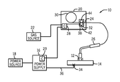
- FIG. 1 is a block diagram of an embodiment of a welding system utilizing a welding torch
- FIG. 2 is a block diagram of an embodiment of the welding system of FIG. 1 , including a travel speed sensing system for detecting a travel speed of the welding torch;
- FIG. 3 illustrates an embodiment of the welding system of FIG. 2 , including a camera monitoring array for determining the travel speed of the welding torch;
- FIG. 4 illustrates an embodiment of the welding system of FIG. 2 , including a camera mounted on the welding torch to determine a travel speed of the welding torch;
- FIG. 5 illustrates an embodiment of the welding system of FIG. 2 , including an optical surface motion sensor module to determine a travel speed of the welding torch;
- FIG. 6 illustrates an embodiment of an optical system that may be associated with the optical motion sensor of FIG. 5 to determine a travel speed of the welding torch;
- FIG. 7 illustrates an embodiment of a mechanical arrangement capable of holding an optical fiber alignment device against a workpiece weld surface
- FIG. 8 illustrates an embodiment of a welding system including a welding glove and an integrated trackball device for determining a travel speed of a welding torch.
- systems and methods for determining the travel speed of a welding device during a welding operation may be used separately or in combination to obtain information during the welding operation relating to the three dimensional speed of the welding torch along the surface of the metal being welded. In some embodiments, these methods may be utilized in unconstrained or manual welding operations to offer advantages over traditional systems in which it may be difficult to measure the weld motion. However, the foregoing systems and methods may be utilized in a variety of suitable welding systems, such as automated or robotic systems.
- Present embodiments are directed toward systems and methods for sensing a travel speed of a welding torch using an optical detection system. More specifically, the disclosed systems include a travel speed sensing system that monitors a light or image associated with the welding system via at least one optical sensor, and detects or determines a travel speed of the welding torch, a direction of torch movement, or both, based on the monitored light. The determined weld travel speed may be utilized to evaluate the heat input to a welding workpiece at a given time. In addition, such information may be utilized to determine a position, velocity, and/or orientation of the welding torch in certain embodiments.
- the travel speed sensing system may include a single optical sensor (e.g., cameras), or an array of optical sensors, located throughout a weld area to detect a light emitted from the welding arc produced by the welding torch.
- array in the following discussion refers to an arrangement of two or more elements (e.g., optical sensors).
- a single optical sensor may be disposed on the welding torch, and the optical sensor may acquire images representative of a surface in a weld area where the workpiece being welded.
- the optical sensor may be part of an optical surface motion sensor that emits light toward the surface of the workpiece, and detects the light reflected from the surface.
- the travel speed sensing system may determine a change in spatial location of the welding torch with respect to time.
- FIG. 1 is a block diagram of an embodiment of a welding system 10 in accordance with the present techniques.
- the welding system 10 is designed to produce a welding arc 12 on a workpiece 14 .
- the welding arc 12 may be of any type of weld, and may be oriented in any desired manner, including MIG, metal active gas (MAG), various waveforms, tandem setup, and so forth.
- the welding system 10 includes a power supply 16 that will typically be coupled to a power source 18 , such as a power grid. Other power sources may, of course, be utilized including generators, engine-driven power packs, and so forth.
- a wire feeder 20 is coupled to a gas source 22 and the power source 18 , and supplies welding wire 24 to a welding torch 26 .
- the welding torch 26 is configured to generate the welding arc 12 between the welding torch 26 and the workpiece 14 .
- the welding wire 24 is fed through the welding torch 26 to the welding arc 12 , molten by the welding arc 12 , and deposited on the workpiece 14 .
- the wire feeder 20 will typically include control circuitry, illustrated generally by reference numeral 28 , which regulates the feed of the welding wire 24 from a spool 30 , and commands the output of the power supply 16 , among other things.
- the power supply 16 may include control circuitry 29 for controlling certain welding parameters and arc-starting parameters.
- the spool 30 will contain a length of welding wire 24 that is consumed during the welding operation.
- the welding wire 24 is advanced by a wire drive assembly 32 , typically through the use of an electric motor under control of the control circuitry 28 .
- the workpiece 14 is coupled to the power supply 16 by a clamp 34 connected to a work cable 36 to complete an electrical circuit when the welding arc 12 is established between the welding torch 26 and the workpiece 14 .
- Placement of the welding torch 26 at a location proximate to the workpiece 14 allows electrical current, which is provided by the power supply 16 and routed to the welding torch 26 , to arc from the welding torch 26 to the workpiece 14 .
- this arcing completes an electrical circuit that includes the power supply 16 , the welding torch 26 , the workpiece 14 , and the work cable 36 .
- electrical current passes from the power supply 16 , to the welding torch 26 , to the workpiece 14 , which is connected back to the power supply 16 .
- the arcing generates a relatively large amount of heat that causes part of the workpiece 14 and the filler metal of the welding wire 24 to transition to a molten state, thereby forming the weld.
- the welding system 10 also feeds an inert shielding gas to the welding torch 26 from the gas source 22 . It is worth noting, however, that a variety of shielding materials for protecting the weld location may be employed in addition to, or in place of, the inert shielding gas, including active gases and particulate solids.
- Presently disclosed embodiments are directed to an optical-based travel speed sensing system used to detect a change in position of the welding torch 26 over time throughout the welding process.
- the travel speed of the welding torch 26 may refer to a change in three dimensional position of the welding torch with respect to time.
- the travel speed of the welding torch 26 may refer to a change in two dimensional position of the welding torch 26 within a plane parallel to a welded surface of the workpiece 14 .
- FIG. 1 illustrates a gas metal arc welding (GMAW) system
- GTAW gas tungsten arc welding
- SMAW shielded metal arc welding
- embodiments of the optical detection based travel speed sensing systems may be utilized with welding systems that include the wire feeder 20 and gas source 22 or with systems that do not include a wire feeder and/or a gas source, depending on implementation-specific considerations.
- FIG. 2 is a block diagram of an embodiment of the welding system 10 , including a travel speed sensing system 50 in accordance with presently disclosed techniques.
- the travel speed sensing system 50 may include, among other things, a travel speed monitoring device 52 configured to process signals received from one or more optical sensors 54 disposed about a weld area 56 .
- the optical sensors 54 may be any desirable type of sensor that converts light into a signal 62 .
- the optical sensors 54 may include any number or arrangement of cameras disposed about the weld area 56 .
- the signal 62 generated by the optical sensors 54 may include image data (e.g., pixel values) or any other appropriate arrangement of data representative of light intensity.
- the weld area 56 may include a weld cell within which a welding operator is using the welding system 10 to perform a welding operation.
- the weld area 56 may include a surface or structure upon which the workpiece 14 is located throughout the welding process, or the workpiece 14 itself.
- the optical sensor 54 may be used to monitor a light 58 that is indicative of the position of the welding torch 26 , and the light 58 may come from a light source 60 within the weld area 56 .
- the light 58 may be emitted directly from the welding arc 12 produced by the welding torch 26 .
- the light 58 may be reflected from a surface in the weld area 56 .
- the one or more optical sensors 54 may convert the light 58 incident on the optical sensors 54 into one or more signals 62 , which may include image data.
- the travel speed sensing system 50 may then transmit the signals 62 to a processor 64 of the travel speed monitoring device 52 .
- the travel speed monitoring device 52 may include the processor 64 , which receives inputs such as image data from the optical sensors 54 via the signal 62 .
- Each signal 62 may be communicated over a communication cable, or wireless communication system, from the one or more optical sensors 54 located throughout the weld area 56 .
- the processor 64 may also send control commands to a control device 66 of the welding system 10 in order to implement appropriate actions within the welding system 10 .
- the control device 66 may control a welding parameter (e.g., power output, wire feed speed, gas flow, etc.) based on the determined travel speed of the welding torch 26 .
- the processor 64 also may be coupled with a display 68 of the travel speed monitoring device 52 , and the display 68 may provide a visual indicator of the travel speed of the welding torch 26 based on the determined travel speed.
- the processor 64 is generally coupled to a memory 70 , which may include one or more software modules 72 that contain executable instructions, transient data, input/output correlation data, and so forth.
- the memory 70 may include volatile or non-volatile memory such as magnetic storage memory, optical storage memory, or a combination thereof.
- the memory 70 may include a variety of machine readable and executable instructions (e.g., computer code) configured to provide a calculation of weld travel speed, given input optical-based sensor data.
- the processor 64 receives such sensor data from the one or more optical sensors 54 in the weld area 56 , and references data stored in the memory 70 to implement such calculation. In this way, the processor 64 is configured to determine a travel speed of the welding torch 26 , based at least in part on the signal 62 .
- the travel speed sensing system 50 may be provided as an integral part of the welding system 10 of FIG. 1 . That is, the travel speed sensing system 50 may be integrated into a component of the welding system 10 , for example, during manufacturing of the welding system 10 .
- the power supply 16 may include appropriate computer code programmed into the software to support the travel speed sensing system 50 .
- the travel speed sensing system 50 may be provided as a retrofit kit that may enable existing welding systems 10 with the optical-based travel speed sensing capabilities described herein.
- the retrofit kit may include, for example, the travel speed sensing system 50 , having the processor 64 and the memory 70 , as well as one or more optical sensors 54 from which the travel speed sensing system 50 receives sensor input.
- the retrofit kit may also include the welding torch 26 , having the optical sensor 54 and/or a light emitting device installed thereon.
- such retrofit kits may be configured as add-ons that may be installed onto existing welding systems 10 , providing travel speed sensing capabilities. Further, as the retrofit kits may be installed on existing welding systems 10 , they may also be configured to be removable once installed.
- FIG. 3 illustrates an embodiment of the welding system 10 of FIG. 2 , capable of determining the travel speed of the welding torch 26 during a welding operation.
- the welding torch 26 is utilized to produce the welding arc 12 on the workpiece 14 , which is a metal pipe in the depicted example.
- the illustrated welding system 10 also includes the travel speed sensing system 50 , in which the one or more optical sensors 54 include a camera monitoring array 90 surrounding the weld area 56 .
- the camera monitoring array 90 includes a plurality of cameras 92 , 94 , 96 , 98 , 100 , 102 , and 104 spaced about the weld area 56 .
- each camera may include an imager or a precision spaced and aligned dual imager stereo camera.
- the cameras may be arranged so that two or more cameras maintain a suitable line of sight to the welding arc 12 at a given time.
- the cameras 92 , 94 , and 96 maintain lines of sight represented by arrows 106 , 108 , and 110 , respectively, to the welding arc 12 .
- the cameras may determine the location of the welding arc 12 using image processing techniques, such as stereo image comparison, triangulation, pixel mapping, or any other suitable technique known to those skilled in the art.
- the camera monitoring array 90 may be used to monitor changes in the position of the welding torch 26 by identifying light emitted from the welding arc 12 . That is, the welding arc 12 functions as the light source 60 of the travel speed sensing system 50 in the illustrated embodiment.
- light filters may be placed between the imager and the welding torch 26 to reduce or eliminate the background light reaching the imager. The foregoing feature may offer the advantage of simplifying the process of removing background light from the image. Further, in some embodiments, the filters may also be designed to reduce the bright light directly from the welding arc 12 to a smaller, more point-like emission from the brightest point of the welding arc 12 for position localization.
- the welding motion is limited to a plane or other predefined surfaces
- a single imager may be utilized to determine the position of the welding torch 26 , assuming the welding arc 12 is visible to the imager.
- two or more cameras may be utilized to locate the welding arc 12 , and the travel speed sensing system 50 may calculate changes in position of the welding torch 26 with respect to time using any suitable stereo or geometric triangulation techniques.
- each camera illustrated in FIG. 3 may represent a stereo camera pair, and each pair may be mounted in a single housing to monitor the welding operation.
- the alignment and spacing of each imager pair mounted in a single housing may be controlled to address implementation-specific alignment or calibration parameters of the travel speed sensing system 50 .
- each stereo camera may be a “smart” camera having onboard processing hardware capable of processing the received images and sharing a relative location of the welding arc 12 with the travel speed monitoring device 52 , thus reducing the amount of information to be shared by the camera array network and reducing the computational power necessary at the processor 64 .
- FIG. 4 illustrates another embodiment of the welding system 10 of FIG. 2 , including the travel speed sensing system 50 used to determine a travel speed of the welding torch 26 .
- the one or more optical sensors 54 include a camera 120 mounted to the welding torch 26 .
- the camera 120 may be used to monitor changes in the position of the welding torch 26 by identifying a region 122 of a surface 124 of the workpiece 14 .
- the region 122 may be identified on surfaces located throughout the weld area 56 that are not limited to the surface 124 of the workpiece 14 .
- the surface could be a surface of a structure upon which the workpiece 14 is located.
- the region 122 detected by the camera 120 changes as the welding torch 26 is moved relative to the workpiece 14 . It may be desirable for the camera 120 to be mounted to the welding torch 26 such that a line of sight 126 of the camera is substantially parallel (e.g., within 5 degrees) with an axis of a torch tip 128 of the welding torch 26 .
- the camera 120 may include a range finding mechanism (e.g., dual imager stereo camera) used to determine a distance between the camera 120 and the surface 124 , and the travel speed sensing system 50 may determine the travel speed of the welding torch 26 partly based on this distance.
- the travel speed monitoring device 52 may use the determined distance to correct for changes in tip-to-work distance of the welding torch 26 throughout welding.
- Other types of range finding mechanisms may include sonic ranging systems, acoustic range finders, and laser range finders, among others.
- the travel speed sensing system 50 may utilize any number of suitable image processing techniques to determine travel speed of the welding torch 26 based on the monitored image. For example, certain features visible in the region 122 may be detected at different positions within the image collected via the camera 120 throughout the welding operation. The processor 64 may compare these positions via optical flow algorithms (e.g., pixel mapping techniques) to determine the distance traveled by the welding torch 26 over a given time interval, thus determining the travel speed of the welding torch 26 .
- optical flow algorithms e.g., pixel mapping techniques
- the workpiece 14 may be prepared with incremental markings such that the position of the welding torch 26 may be determined based on the images acquired via the camera 120 , if an initial position and orientation of the welding torch 26 are known.
- the surface 124 may be modified by the application of a high contrast pattern to enhance the ability of the travel speed sensing system 50 to track torch motion.
- the pattern may be applied to the surface 124 as tape, paint, or projected light.
- the pattern may provide edges or regions of alternating light intensity when viewed by the optical sensor 54 , and these edges may allow the travel speed sensing system 50 to more easily track the relative motion between the camera 120 and the monitored surface 124 .
- the pattern may include, for example, checkerboard tape applied to the surface 124 , white paint with black speckle spray painted on the surface 124 , or a grid of light projected onto the surface 124 by a laser or LED.
- one or more additional cameras may be located at any other suitable location around the welding torch 26 , for example, on an opposite side of the welding torch 26 .
- this additional camera may provide surface motion information that may be used to detect a rotation of the welding torch 26 and/or a tip-to-work distance of the welding torch 26 that may not be available using only one camera.
- the multiple cameras may provide redundant surface motion information that may be utilized if the direction of welding points one of the two cameras 120 toward a hot/molten trailing weld bead. Light emitted from the weld bead may otherwise saturate or obscure the light information collected via the camera 120 .
- the camera 120 may be configured to operate with a relatively high dynamic range (e.g., utilizing a logarithmic optical sensor) to avoid saturation of the images due to flashing of the welding arc 12 .
- a relatively high dynamic range e.g., utilizing a logarithmic optical sensor
- the travel speed monitoring device 52 may utilize multiple exposure techniques to correct for saturation of the images collected. More specifically, the camera 120 may acquire multiple images and send the image data to the processor 64 , which then combines the images to determine an image with a desired exposure. The processor 64 then processes this new image to determine the weld travel speed of the welding torch 26 .
- a protective covering may be disposed over the optical sensor 54 to protect the optical sensor 54 from weld spatter.
- This protective covering may include a plastic and/or optically clear covering that weld spatter does not readily stick to or pit.
- FIGS. 5-7 illustrate additional embodiments of systems and methods capable of determining the travel speed of the welding torch 26 by utilizing a variety of optical arrangements.
- FIG. 5 illustrates an embodiment of the welding system 10 of FIG. 2 wherein the travel speed sensing system 50 includes an optical surface motion sensor 130 disposed on the welding torch 26 .
- the optical sensor 54 and the light source 60 are located in the optical surface motion sensor 130 .
- the optical surface motion sensor 130 is configured to output light toward the surface 124 of the workpiece 14 via the surface illumination light source and to monitor the light reflected from the surface 124 via the optical sensor 54 .
- surface illumination light is carried from the illumination light source by an illumination optical fiber 132 closer to the surface 124 of the workpiece 14 being welded.
- illumination optical fiber 132 During operation, light exits the illumination optical fiber 132 , strikes the nearby surface 124 of the workpiece 14 and some of this light is reflected.
- a light collection optical fiber 134 captures at least a portion of the reflected light and transmits it back to the optical sensor 54 located in the optical surface motion sensor 130 .
- the fibers 132 and 134 may be made of any suitable material capable of withstanding typical weld temperatures, such as high temperature glass/plastic that is cladded, coated, or jacketed with high temperature resistant material.
- the numerical aperture of the optical fibers may be chosen to optimize the collection of reflected/scattered light from the surface 124 .
- an optical fiber alignment device 136 holds and maintains the optical fibers at the desired angle such that the central ray of light emitted from the illumination optical fiber 132 enters the center of the light collection optical fiber 134 if it experiences specular reflection from the surface 124 when the welding angle is approximately zero degrees.
- the optical fiber alignment device 136 also holds the fibers relative to the torch tip 128 .
- the optical fiber alignment device 136 may include collimators, lenses, or filters to maximize the reflected light collected and minimize light entering the optical fibers directly from the welding arc 12 .
- an additional pair of illumination and light collection optical fibers may be located at any other suitable location around the welding torch 26 , for example, on the opposite side of the torch tip 128 .
- this additional pair of fibers may be connected to separate illumination light sources and light sensors in the optical surface motion sensor 130 , thereby providing redundant surface motion information. This redundancy may be desirable if the direction of welding points one of the two pairs of sensors at a hot/molten trailing weld bead 138 .
- the optical sensor 54 which may be a multiple pixel image sensor.
- successive high speed images may be acquired and compared to enable tracking of the motion of features in the image as a function of time across the pixels of the imager.
- the rate of translation of these features across the imager field of view may be interpreted as a weld travel speed corresponding to the travel speed of the welding torch 26 throughout the welding operation, assuming the distance between the imager and the surface 124 remains relatively constant and the angle at which the imager views the surface 124 remains relatively constant.
- phase-based algorithms may be utilized in the image processing schemes as well. Such techniques may be particularly useful in variable lighting conditions, such as those experienced near the welding arc 12 . That is, phase based algorithms may be less susceptible to changes in brightness from frame to frame due to variable lighting produced by the welding arc 12 . These algorithms may utilize, for example, a Fourier transform, convolution with Gabor filters, high-pass or band-pass filtering, or any other appropriate methods to estimate a local phase in the image before processing with an optical flow algorithm.
- the local phase may include features (e.g., edges) that are not easily identifiable based on light intensity.
- the travel speed monitoring device 52 may estimate the local phase, and then monitor regional changes in the phase over time (e.g., successive images) to estimate a relative motion of the welding torch 26 .
- the travel speed sensing system 50 may apply optical flow algorithms that utilize the estimated local phase from at least a portion of collected images to determine the overall motion, and thus weld travel speed.
- FIG. 6 illustrates an embodiment of certain components that may be present in the optical surface motion sensor 130 located on the welding torch 26 of FIG. 5 .
- light is emitted from a light source 150 (e.g., a laser) coupled to the illumination optical fiber 132 .
- the light travels down the illumination optical fiber 132 and through a lens 152 held within the optical fiber alignment device 136 .
- Light is emitted at an angle 154 with respect to the optical fiber alignment device 136 , as indicated by arrow 156 .
- a portion of the light reflects off of the surface 124 of the workpiece 14 and reaches the entrance to the light collection optical fiber 134 , as indicated by arrow 158 .
- the light passes through collimators or filters 160 and a lens 162 before entering the light collection optical fiber 134 .
- the angle 154 may be based upon an average expected tip-to-work distance 164 such that specular reflections will enter the light collection optical fiber 134 that is angled at an opposing (but similar value) angle 166 .
- the light that exits the light collection optical fiber 134 enters a lens 168 that focuses the light upon an imager 170 .
- the light source 150 may output a narrow band of light frequencies, and the filters 160 may be configured to accept primarily those frequencies emitted by the light source 150 . This may increase a signal to noise ratio of the light collected from the light source 50 as compared with external variable intensity lighting.
- the optical surface motion sensor 130 is configured to filter the light reflected from the surface 124 via the filters 160 to produce a filtered light at one or more desired frequencies, so that only the filtered light is sensed via the imager 170 .
- this type of optical surface motion sensor 130 may be used in a redundant system to detect a distance from the optical surface motion sensor 130 to the workpiece 14 .
- the optical surface motion sensor 130 may automatically adjust a focus length of the imaging system based on the detected distance from the sensor to the workpiece 14 .
- the optical fibers 132 , 134 may enable delicate electronics located in the optical surface motion sensor 130 to be mounted at a location of the welding torch 26 away from the welding arc 12 . In other embodiments, however, the optical surface motion sensor 130 may be mounted to the welding torch 26 near the torch tip 128 .
- Such optical surface motion sensors 130 may include relatively heat-resistant, shock-resistance imagers that monitor the surface 124 directly through a lens, and not via optical fibers.
- the angle of the welding torch 26 relative to the surface 124 may vary over time during a welding operation. It may be desirable for the welding system 10 to be capable of correcting for such changes in welding torch position, in order to determine an accurate weld travel speed.
- the torch angle or changes in the torch angle over time may be sensed and utilized to correct the travel speed estimate.
- an inclinometer 172 such as an electrolytic tilt sensor or low-G triaxial accelerometer, may be placed on the welding torch 26 to measure torch angle, thus enabling changes in the angle of the welding torch 26 to be monitored.
- any of a variety of suitable techniques may be utilized to monitor and accommodate changes in the torch angle of the welding torch 26 .
- the optical fiber alignment device 136 may be placed in contact with the surface 124 .
- FIG. 7 illustrates an embodiment of the welding system 10 , including a suitable mechanical arrangement for holding the optical fiber alignment or mechanical rolling device 136 against the surface 124 of the workpiece 14 .
- the illustrated arrangement may maintain the optical fiber alignment device 136 in this position for a variety of torch angles (i.e., angles from the welding torch 26 to the surface 124 ) and a range of distances from the torch tip 128 to surface 124 .
- the optical fiber alignment device 136 is connected to the welding torch 26 by a mechanical linkage assembly 180 , which may include an attachment ring 182 , an upper link 184 , a lower link 186 , a return force element 188 , and a joint 190 .
- the attachment ring 182 enables the upper link 184 to be positioned through a range of angles rotating around an axis parallel to the major axis of the torch tip 128 . This rotation may enable an operator to place the optical fiber alignment device 136 in a location that will not interfere with the weld bead 138 or obstacles associated with the surface 124 and will not block the operator's field of view of the welding arc 12 .
- the upper link 184 is connected to the lower link 186 by a sliding linkage that allows the upper and lower link to slide relative to one another along their lengths.
- the sliding linkage includes a return force element 188 , such as a spring, to allow the optical fiber alignment device 136 to maintain contact with the surface 124 as the distance between the welding torch 26 and surface 124 changes.
- the lower link 186 is attached to the optical fiber alignment device 136 by the joint 190 , which may be a ball joint.
- the joint 190 may enable the relative angle between the optical fiber alignment device 136 and the lower link 186 to change such that the optical fiber alignment device 136 and the surface 124 maintain a substantially constant contact angle.
- the illumination optical fiber 132 and the light collection optical fiber 134 may be held at predetermined locations to the welding torch 26 and/or to the mechanical linkage assembly 180 in a way that holds the fibers while enabling them to flex or translate with the linkage, while reducing mechanical stress induced in the fibers.
- FIG. 8 illustrates an embodiment of components of the travel speed sensing system 50 including a welding glove 200 and a trackball device 202 .
- One or more low-profile trackballs 204 may be located on the welding glove 200 , such as in a region 206 of the welding glove 200 where the operator might naturally drag the welding glove 200 across the surface 124 while welding.
- the trackball device 202 may be located on any other suitable welding accessory, such as on a wristband or armband worn by the operator or at the end of the mechanical linkage assembly 180 described above and shown in FIG. 7 .
- the trackball 204 or other mechanical roller may be an optical surface motion sensor configured to be moved across the surface 124 .
- the trackball 204 may be any suitable mechanical device, such as a cylinder or wheel, that could be used to measure an instantaneous speed of the welding glove 200 and, therefore, of the welding torch 26 , across the workpiece 14 .
- the trackball 204 may include one or more low profile balls incorporated into the welding glove 200 .
- the trackball device 202 may be incorporated into the welding glove 200 along an edge of the welding glove 200 near the lower palm on the pinkie finger side of the welding glove 200 .
- rotation of the trackballs 204 may be translated into a speed of the welding glove 200 along the surface 124 as long as the balls maintain contact with the surface 124 .
- the trackball 204 may be made of a material capable of withstanding high temperatures typically associated with the workpiece 14 . This may reduce any undesirable deformation of the trackball 204 as it grips the metal, so that slippage does not occur if the welding glove 200 is drug across the surface 124 with light pressure against the surface 124 .
- Rotation of the trackballs 204 may be measured with suitable optical encoders included in the trackball device 202 .
- the trackball 204 may have a pattern on its surface to enable the use of optical image processors to measure a rate of rotation in any direction of the trackball 204 .
- Other standard encoder methods for measuring ball rotation may be used in other embodiments.
- a single trackball 204 is utilized.
- multiple balls may be distributed over the edge and heel of the welding glove 200 , thereby enabling greater variation in the welder hand position and contact points with the surface 124 being welded.
- signals (e.g., 62 ) from the plurality of balls may be combined, for example, via averaging, after selecting only the balls fully involved (continuously moving) in motion detection at a given moment.
- glove trackball electronics may be battery powered, and the signal 62 from the glove trackball may be wirelessly transmitted to the travel speed monitoring device 52 to eliminate the need for wires to the welding glove 200 .
- the surface 124 may be monitored via an optical surface motion sensor, such as the optical surface motion sensor 130 of FIGS. 5-7 .
- the light source 60 and the optical sensor 54 may be integrated into a device built into the region 206 of the welding glove 200 to be placed in contact with the surface 124 .
- a glove structure housing the light source 60 and the optical sensor 54 may be designed to maintain a desired distance between the optical sensor 54 and the surface 124 for proper focusing.
- Such a glove structure could be made of a smooth, relatively low friction material to allow the welding glove 200 to slide across the surface 124 .
Abstract
Description
Claims (22)
Priority Applications (4)
| Application Number | Priority Date | Filing Date | Title |
|---|---|---|---|
| US13/740,964 US9522437B2 (en) | 2012-02-10 | 2013-01-14 | Optical-based weld travel speed sensing system |
| PCT/US2013/025071 WO2013122805A1 (en) | 2012-02-10 | 2013-02-07 | Optical-based weld travel speed sensing system |
| US15/384,085 US11612949B2 (en) | 2012-02-10 | 2016-12-19 | Optical-based weld travel speed sensing system |
| US17/031,394 US20210016382A1 (en) | 2012-02-10 | 2020-09-24 | Optical-based weld travel speed sensing system |
Applications Claiming Priority (2)
| Application Number | Priority Date | Filing Date | Title |
|---|---|---|---|
| US201261597556P | 2012-02-10 | 2012-02-10 | |
| US13/740,964 US9522437B2 (en) | 2012-02-10 | 2013-01-14 | Optical-based weld travel speed sensing system |
Related Child Applications (1)
| Application Number | Title | Priority Date | Filing Date |
|---|---|---|---|
| US15/384,085 Continuation US11612949B2 (en) | 2012-02-10 | 2016-12-19 | Optical-based weld travel speed sensing system |
Publications (2)
| Publication Number | Publication Date |
|---|---|
| US20130206740A1 US20130206740A1 (en) | 2013-08-15 |
| US9522437B2 true US9522437B2 (en) | 2016-12-20 |
Family
ID=48944758
Family Applications (8)
| Application Number | Title | Priority Date | Filing Date |
|---|---|---|---|
| US13/738,770 Active 2035-02-16 US9573215B2 (en) | 2012-02-10 | 2013-01-10 | Sound-based weld travel speed sensing system and method |
| US13/740,964 Active 2035-07-12 US9522437B2 (en) | 2012-02-10 | 2013-01-14 | Optical-based weld travel speed sensing system |
| US13/755,984 Active 2035-06-12 US9511443B2 (en) | 2012-02-10 | 2013-01-31 | Helmet-integrated weld travel speed sensing system and method |
| US15/369,474 Active 2034-09-13 US10596650B2 (en) | 2012-02-10 | 2016-12-05 | Helmet-integrated weld travel speed sensing system and method |
| US15/384,085 Active 2033-11-21 US11612949B2 (en) | 2012-02-10 | 2016-12-19 | Optical-based weld travel speed sensing system |
| US16/828,178 Active 2033-04-29 US11590596B2 (en) | 2012-02-10 | 2020-03-24 | Helmet-integrated weld travel speed sensing system and method |
| US17/031,394 Pending US20210016382A1 (en) | 2012-02-10 | 2020-09-24 | Optical-based weld travel speed sensing system |
| US18/110,064 Pending US20230191522A1 (en) | 2012-02-10 | 2023-02-15 | Helmet-integrated weld travel speed sensing system and method |
Family Applications Before (1)
| Application Number | Title | Priority Date | Filing Date |
|---|---|---|---|
| US13/738,770 Active 2035-02-16 US9573215B2 (en) | 2012-02-10 | 2013-01-10 | Sound-based weld travel speed sensing system and method |
Family Applications After (6)
| Application Number | Title | Priority Date | Filing Date |
|---|---|---|---|
| US13/755,984 Active 2035-06-12 US9511443B2 (en) | 2012-02-10 | 2013-01-31 | Helmet-integrated weld travel speed sensing system and method |
| US15/369,474 Active 2034-09-13 US10596650B2 (en) | 2012-02-10 | 2016-12-05 | Helmet-integrated weld travel speed sensing system and method |
| US15/384,085 Active 2033-11-21 US11612949B2 (en) | 2012-02-10 | 2016-12-19 | Optical-based weld travel speed sensing system |
| US16/828,178 Active 2033-04-29 US11590596B2 (en) | 2012-02-10 | 2020-03-24 | Helmet-integrated weld travel speed sensing system and method |
| US17/031,394 Pending US20210016382A1 (en) | 2012-02-10 | 2020-09-24 | Optical-based weld travel speed sensing system |
| US18/110,064 Pending US20230191522A1 (en) | 2012-02-10 | 2023-02-15 | Helmet-integrated weld travel speed sensing system and method |
Country Status (2)
| Country | Link |
|---|---|
| US (8) | US9573215B2 (en) |
| WO (3) | WO2013119768A1 (en) |
Cited By (11)
| Publication number | Priority date | Publication date | Assignee | Title |
|---|---|---|---|---|
| US20160207134A1 (en) * | 2015-01-20 | 2016-07-21 | Illinois Tool Works Inc. | Weld output control by a welding vision system |
| CN109759676A (en) * | 2019-03-06 | 2019-05-17 | 河海大学常州校区 | Manual welding speed detection device |
| CN109926696A (en) * | 2019-03-06 | 2019-06-25 | 河海大学常州校区 | A kind of arc light capture mechanism for Manual welding speed detection |
| WO2020028621A1 (en) | 2018-08-03 | 2020-02-06 | Illinois Tool Works Inc. | System and method for weld training |
| US10762802B2 (en) | 2008-08-21 | 2020-09-01 | Lincoln Global, Inc. | Welding simulator |
| US10803770B2 (en) | 2008-08-21 | 2020-10-13 | Lincoln Global, Inc. | Importing and analyzing external data using a virtual reality welding system |
| US10878591B2 (en) | 2016-11-07 | 2020-12-29 | Lincoln Global, Inc. | Welding trainer utilizing a head up display to display simulated and real-world objects |
| US10913125B2 (en) | 2016-11-07 | 2021-02-09 | Lincoln Global, Inc. | Welding system providing visual and audio cues to a welding helmet with a display |
| US10930174B2 (en) | 2013-05-24 | 2021-02-23 | Lincoln Global, Inc. | Systems and methods providing a computerized eyewear device to aid in welding |
| US10997872B2 (en) | 2017-06-01 | 2021-05-04 | Lincoln Global, Inc. | Spring-loaded tip assembly to support simulated shielded metal arc welding |
| US11922644B2 (en) | 2022-02-11 | 2024-03-05 | Illinois Tool Works Inc. | Calibration procedures for helmet based weld tracking systems |
Families Citing this family (127)
| Publication number | Priority date | Publication date | Assignee | Title |
|---|---|---|---|---|
| US9104195B2 (en) | 2006-12-20 | 2015-08-11 | Lincoln Global, Inc. | Welding job sequencer |
| US10994358B2 (en) | 2006-12-20 | 2021-05-04 | Lincoln Global, Inc. | System and method for creating or modifying a welding sequence based on non-real world weld data |
| US9937577B2 (en) | 2006-12-20 | 2018-04-10 | Lincoln Global, Inc. | System for a welding sequencer |
| WO2009065087A1 (en) | 2007-11-14 | 2009-05-22 | Biosensors International Group, Ltd. | Automated coating apparatus and method |
| WO2009146359A1 (en) | 2008-05-28 | 2009-12-03 | Illinois Tool Works Inc. | Welding training system |
| US9280913B2 (en) * | 2009-07-10 | 2016-03-08 | Lincoln Global, Inc. | Systems and methods providing enhanced education and training in a virtual reality environment |
| US9773429B2 (en) | 2009-07-08 | 2017-09-26 | Lincoln Global, Inc. | System and method for manual welder training |
| US9221117B2 (en) | 2009-07-08 | 2015-12-29 | Lincoln Global, Inc. | System for characterizing manual welding operations |
| US10748447B2 (en) * | 2013-05-24 | 2020-08-18 | Lincoln Global, Inc. | Systems and methods providing a computerized eyewear device to aid in welding |
| US9993891B2 (en) | 2010-07-14 | 2018-06-12 | Illinois Tool Works Inc. | Welding parameter control via welder motion or position monitoring |
| CA2821671C (en) | 2010-12-13 | 2018-01-09 | Edison Welding Institute, Inc. | Welding training system |
| US9101994B2 (en) | 2011-08-10 | 2015-08-11 | Illinois Tool Works Inc. | System and device for welding training |
| US9573215B2 (en) | 2012-02-10 | 2017-02-21 | Illinois Tool Works Inc. | Sound-based weld travel speed sensing system and method |
| JP5843683B2 (en) * | 2012-03-28 | 2016-01-13 | 株式会社神戸製鋼所 | Tandem welding torch |
| ES2438440B1 (en) * | 2012-06-13 | 2014-07-30 | Seabery Soluciones, S.L. | ADVANCED DEVICE FOR SIMULATION-BASED WELDING TRAINING WITH INCREASED REALITY AND REMOTE UPDATE |
| US20140005807A1 (en) * | 2012-06-29 | 2014-01-02 | Black & Decker Inc. | System for Enhancing Operation of Power Tools |
| US20160093233A1 (en) | 2012-07-06 | 2016-03-31 | Lincoln Global, Inc. | System for characterizing manual welding operations on pipe and other curved structures |
| US9368045B2 (en) | 2012-11-09 | 2016-06-14 | Illinois Tool Works Inc. | System and device for welding training |
| US9583014B2 (en) | 2012-11-09 | 2017-02-28 | Illinois Tool Works Inc. | System and device for welding training |
| KR101473639B1 (en) * | 2013-02-25 | 2014-12-17 | 대우조선해양 주식회사 | Large volume butt joint welding apparatus and the method thereof |
| US10213861B2 (en) * | 2013-03-11 | 2019-02-26 | Illinois Tool Works Inc. | Automated system for machine set-up of welding power sources and welding systems |
| US9583023B2 (en) | 2013-03-15 | 2017-02-28 | Illinois Tool Works Inc. | Welding torch for a welding training system |
| US9728103B2 (en) * | 2013-03-15 | 2017-08-08 | Illinois Tool Works Inc. | Data storage and analysis for a welding training system |
| US9672757B2 (en) | 2013-03-15 | 2017-06-06 | Illinois Tool Works Inc. | Multi-mode software and method for a welding training system |
| US9666100B2 (en) | 2013-03-15 | 2017-05-30 | Illinois Tool Works Inc. | Calibration devices for a welding training system |
| US9713852B2 (en) | 2013-03-15 | 2017-07-25 | Illinois Tool Works Inc. | Welding training systems and devices |
| JP6138566B2 (en) * | 2013-04-24 | 2017-05-31 | 川崎重工業株式会社 | Component mounting work support system and component mounting method |
| US11090753B2 (en) * | 2013-06-21 | 2021-08-17 | Illinois Tool Works Inc. | System and method for determining weld travel speed |
| EP2829890B1 (en) * | 2013-07-25 | 2019-12-11 | C.R.F. Società Consortile per Azioni | System for ultrasound localization of a tool in a workspace, corresponding method and program product |
| US20150072323A1 (en) | 2013-09-11 | 2015-03-12 | Lincoln Global, Inc. | Learning management system for a real-time simulated virtual reality welding training environment |
| US10083627B2 (en) | 2013-11-05 | 2018-09-25 | Lincoln Global, Inc. | Virtual reality and real welding training system and method |
| US10056010B2 (en) | 2013-12-03 | 2018-08-21 | Illinois Tool Works Inc. | Systems and methods for a weld training system |
| US9757819B2 (en) | 2014-01-07 | 2017-09-12 | Illinois Tool Works Inc. | Calibration tool and method for a welding system |
| US10105782B2 (en) | 2014-01-07 | 2018-10-23 | Illinois Tool Works Inc. | Feedback from a welding torch of a welding system |
| US10170019B2 (en) | 2014-01-07 | 2019-01-01 | Illinois Tool Works Inc. | Feedback from a welding torch of a welding system |
| US9751149B2 (en) | 2014-01-07 | 2017-09-05 | Illinois Tool Works Inc. | Welding stand for a welding system |
| US9724788B2 (en) | 2014-01-07 | 2017-08-08 | Illinois Tool Works Inc. | Electrical assemblies for a welding system |
| US9589481B2 (en) | 2014-01-07 | 2017-03-07 | Illinois Tool Works Inc. | Welding software for detection and control of devices and for analysis of data |
| US9836987B2 (en) | 2014-02-14 | 2017-12-05 | Lincoln Global, Inc. | Virtual reality pipe welding simulator and setup |
| WO2015185972A1 (en) | 2014-06-02 | 2015-12-10 | Lincoln Global, Inc. | System and method for manual welder training |
| US10335883B2 (en) | 2014-06-05 | 2019-07-02 | Illinois Tool Works Inc. | Gravity-based weld travel speed sensing system and method |
| US9862049B2 (en) | 2014-06-27 | 2018-01-09 | Illinois Tool Works Inc. | System and method of welding system operator identification |
| US9937578B2 (en) * | 2014-06-27 | 2018-04-10 | Illinois Tool Works Inc. | System and method for remote welding training |
| US10307853B2 (en) | 2014-06-27 | 2019-06-04 | Illinois Tool Works Inc. | System and method for managing welding data |
| US10665128B2 (en) | 2014-06-27 | 2020-05-26 | Illinois Tool Works Inc. | System and method of monitoring welding information |
| US11014183B2 (en) * | 2014-08-07 | 2021-05-25 | Illinois Tool Works Inc. | System and method of marking a welding workpiece |
| US9724787B2 (en) | 2014-08-07 | 2017-08-08 | Illinois Tool Works Inc. | System and method of monitoring a welding environment |
| US9875665B2 (en) | 2014-08-18 | 2018-01-23 | Illinois Tool Works Inc. | Weld training system and method |
| US10446057B2 (en) | 2014-09-19 | 2019-10-15 | Realityworks, Inc. | Welding speed sensor |
| US10643495B2 (en) | 2014-09-19 | 2020-05-05 | Realityworks, Inc. | Welding speed pacing device |
| US10201868B2 (en) | 2014-09-30 | 2019-02-12 | Illinois Tool Works Inc. | Systems and methods for gesture control of a welding system |
| US10987762B2 (en) | 2014-09-30 | 2021-04-27 | Illinois Tool Works Inc. | Armband based systems and methods for controlling welding equipment using gestures and like motions |
| JP6358032B2 (en) * | 2014-10-14 | 2018-07-18 | 新日鐵住金株式会社 | Velocity measuring device and velocity measuring method |
| US11247289B2 (en) * | 2014-10-16 | 2022-02-15 | Illinois Tool Works Inc. | Remote power supply parameter adjustment |
| US10239147B2 (en) | 2014-10-16 | 2019-03-26 | Illinois Tool Works Inc. | Sensor-based power controls for a welding system |
| US9922460B2 (en) * | 2014-11-04 | 2018-03-20 | Illinois Tool Works Inc. | Stereoscopic helmet display |
| US10402959B2 (en) | 2014-11-05 | 2019-09-03 | Illinois Tool Works Inc. | System and method of active torch marker control |
| US10210773B2 (en) | 2014-11-05 | 2019-02-19 | Illinois Tool Works Inc. | System and method for welding torch display |
| US10204406B2 (en) | 2014-11-05 | 2019-02-12 | Illinois Tool Works Inc. | System and method of controlling welding system camera exposure and marker illumination |
| US20160125762A1 (en) * | 2014-11-05 | 2016-05-05 | Illinois Tool Works Inc. | System and method for welding system clamp assembly |
| US10417934B2 (en) | 2014-11-05 | 2019-09-17 | Illinois Tool Works Inc. | System and method of reviewing weld data |
| US10490098B2 (en) | 2014-11-05 | 2019-11-26 | Illinois Tool Works Inc. | System and method of recording multi-run data |
| US10373304B2 (en) | 2014-11-05 | 2019-08-06 | Illinois Tool Works Inc. | System and method of arranging welding device markers |
| WO2016083258A1 (en) * | 2014-11-27 | 2016-06-02 | Nuovo Pignone Srl | Welding assistance device with a welding mask having a velocity sensor |
| ITMI20142041A1 (en) * | 2014-11-27 | 2016-05-27 | Nuovo Pignone Srl | MANIPULATOR EQUIPMENT FOR PERFORMING A TIG WELDING |
| US10449614B2 (en) | 2014-12-18 | 2019-10-22 | Illinois Tool Works Inc. | Systems and methods for solid state sensor measurements of welding cables |
| US11198190B2 (en) * | 2014-12-18 | 2021-12-14 | Illinois Tool Works Inc. | Systems and methods for duplex communications over a welding cable |
| US20160175976A1 (en) * | 2014-12-18 | 2016-06-23 | Illinois Tool Works Inc. | Systems and methods for determining a weld torch location |
| US10828713B2 (en) | 2014-12-18 | 2020-11-10 | Illinois Tool Works Inc. | Systems and methods for adaptively controlling physical layers for weld cable communications |
| US10076802B2 (en) * | 2014-12-19 | 2018-09-18 | Illinois Tool Works Inc. | Electric arc start systems and methods |
| US20160175964A1 (en) * | 2014-12-19 | 2016-06-23 | Lincoln Global, Inc. | Welding vision and control system |
| US9975196B2 (en) | 2015-01-05 | 2018-05-22 | University Of Kentucky Research Foundation | Measurement of three-dimensional welding torch orientation for manual arc welding process |
| US20160193680A1 (en) * | 2015-01-07 | 2016-07-07 | Illinois Tool Works Inc. | Automated welding translation platform |
| US10773329B2 (en) | 2015-01-20 | 2020-09-15 | Illinois Tool Works Inc. | Multiple input welding vision system |
| WO2016118926A1 (en) * | 2015-01-22 | 2016-07-28 | Illinois Tool Works Inc. | Manual tool tracking and guidance with inertial measurement unit |
| EP3247525B1 (en) * | 2015-01-22 | 2020-03-04 | Illinois Tool Works Inc. | Manual tool tracking and guidance with inertial measurement unit |
| US10406638B2 (en) | 2015-02-27 | 2019-09-10 | Illinois Tool Works Inc. | Augmented vision system with active welder guidance |
| US20160250706A1 (en) * | 2015-02-27 | 2016-09-01 | Illinois Tool Works Inc. | Welding system providing remote storage of video weld data |
| EP3265865A1 (en) * | 2015-03-06 | 2018-01-10 | Illinois Tool Works Inc. | Sensor assisted head mounted displays for welding |
| WO2016144744A1 (en) | 2015-03-09 | 2016-09-15 | Illinois Tool Works Inc. | Methods and apparatus to provide visual information associated with welding operations |
| USD806321S1 (en) * | 2015-03-25 | 2017-12-26 | Ringers Technologies, LLC | Pair of anti-fatigue impact welding gloves |
| US9977242B2 (en) | 2015-03-26 | 2018-05-22 | Illinois Tool Works Inc. | Control of mediated reality welding system based on lighting conditions |
| US9666160B2 (en) | 2015-03-26 | 2017-05-30 | Illinois Tool Works Inc. | Control of mediated reality welding system based on lighting conditions |
| US10427239B2 (en) | 2015-04-02 | 2019-10-01 | Illinois Tool Works Inc. | Systems and methods for tracking weld training arc parameters |
| US10722969B2 (en) * | 2015-06-03 | 2020-07-28 | Illinois Tool Works Inc. | Energy conservation system, method, and apparatus for use with welding equipment |
| US10512983B2 (en) | 2015-06-15 | 2019-12-24 | University Of Kentucky Research Foundation | Method and apparatus for measurement of three-dimensional welding torch orientation for a welding process without using a magnetometer |
| US10363632B2 (en) | 2015-06-24 | 2019-07-30 | Illinois Tool Works Inc. | Time of flight camera for welding machine vision |
| WO2017006546A1 (en) * | 2015-07-03 | 2017-01-12 | パナソニックIpマネジメント株式会社 | Distance measurement device and distance image combination method |
| US10593230B2 (en) | 2015-08-12 | 2020-03-17 | Illinois Tool Works Inc. | Stick welding electrode holder systems and methods |
| US10373517B2 (en) | 2015-08-12 | 2019-08-06 | Illinois Tool Works Inc. | Simulation stick welding electrode holder systems and methods |
| US10657839B2 (en) | 2015-08-12 | 2020-05-19 | Illinois Tool Works Inc. | Stick welding electrode holders with real-time feedback features |
| US10438505B2 (en) | 2015-08-12 | 2019-10-08 | Illinois Tool Works | Welding training system interface |
| US9972215B2 (en) | 2015-08-18 | 2018-05-15 | Lincoln Global, Inc. | Augmented reality interface for weld sequencing |
| EP3366404B1 (en) * | 2015-10-23 | 2020-09-16 | Panasonic Intellectual Property Management Co., Ltd. | Welding torch |
| WO2017120488A1 (en) * | 2016-01-08 | 2017-07-13 | Illinois Tool Works Inc. | Systems and methods to provide weld training |
| MX2018008462A (en) | 2016-01-08 | 2018-11-09 | Illinois Tool Works | Systems and methods to provide weld training. |
| CN105921854B (en) * | 2016-05-04 | 2018-02-02 | 江苏科技大学 | A kind of rotating the arc narrow gap MAG welding line deviation identification devices and method |
| EP3319066A1 (en) | 2016-11-04 | 2018-05-09 | Lincoln Global, Inc. | Magnetic frequency selection for electromagnetic position tracking |
| US10579138B2 (en) * | 2016-12-22 | 2020-03-03 | ReScan, Inc. | Head-mounted sensor system |
| US10596651B2 (en) | 2017-07-12 | 2020-03-24 | Illinois Tool Works Inc. | Methods and apparatus to communicate via a welding arc |
| CN109304530A (en) * | 2017-07-26 | 2019-02-05 | 林肯环球股份有限公司 | The system and method that the glasses device of computerization is provided to assist welding |
| US10608888B2 (en) | 2017-12-21 | 2020-03-31 | Lincoln Global, Inc. | Relating an operator to a power source |
| JP7036632B2 (en) * | 2018-03-13 | 2022-03-15 | 株式会社ダイヘン | Arc welding support device, arc welding support method and program |
| US11413698B2 (en) * | 2018-03-13 | 2022-08-16 | General Electric Company | System and method for monitoring and controlling build quality during electron beam manufacturing |
| US11475792B2 (en) | 2018-04-19 | 2022-10-18 | Lincoln Global, Inc. | Welding simulator with dual-user configuration |
| US11557223B2 (en) | 2018-04-19 | 2023-01-17 | Lincoln Global, Inc. | Modular and reconfigurable chassis for simulated welding training |
| DE102018113741A1 (en) * | 2018-06-08 | 2019-12-12 | Chiron-Werke Gmbh & Co. Kg | Apparatus and method for monitoring a picking status of a workpiece |
| DE202018006108U1 (en) * | 2018-12-07 | 2020-03-10 | BIAS - Bremer Institut für angewandte Strahltechnik GmbH | System for determining a welding or soldering speed |
| US11707806B2 (en) * | 2019-02-12 | 2023-07-25 | Illinois Tool Works Inc. | Virtual markings in welding systems |
| US11450233B2 (en) | 2019-02-19 | 2022-09-20 | Illinois Tool Works Inc. | Systems for simulating joining operations using mobile devices |
| US11521512B2 (en) | 2019-02-19 | 2022-12-06 | Illinois Tool Works Inc. | Systems for simulating joining operations using mobile devices |
| US11311958B1 (en) * | 2019-05-13 | 2022-04-26 | Airgas, Inc. | Digital welding and cutting efficiency analysis, process evaluation and response feedback system for process optimization |
| EP3760357A1 (en) * | 2019-07-05 | 2021-01-06 | Ewm Ag | Method and system for determining a welding or soldering speed |
| US11776423B2 (en) | 2019-07-22 | 2023-10-03 | Illinois Tool Works Inc. | Connection boxes for gas tungsten arc welding training systems |
| US11288978B2 (en) | 2019-07-22 | 2022-03-29 | Illinois Tool Works Inc. | Gas tungsten arc welding training systems |
| KR102304917B1 (en) * | 2019-09-20 | 2021-09-27 | 주식회사 오토스윙 | Welding information providing apparatus with sensing function of circumstances |
| JP7333243B2 (en) * | 2019-10-18 | 2023-08-24 | 日立Geニュークリア・エナジー株式会社 | Welding speed calculation system, welding speed calculation method, and welding speed calculation device |
| US11322037B2 (en) | 2019-11-25 | 2022-05-03 | Illinois Tool Works Inc. | Weld training simulations using mobile devices, modular workpieces, and simulated welding equipment |
| US11721231B2 (en) | 2019-11-25 | 2023-08-08 | Illinois Tool Works Inc. | Weld training simulations using mobile devices, modular workpieces, and simulated welding equipment |
| DE102019134555A1 (en) * | 2019-12-16 | 2021-06-17 | Audi Ag | System for monitoring a welding process |
| CN111679090A (en) * | 2020-06-16 | 2020-09-18 | 南京云岗智能科技有限公司 | Welding speed detection device for manual welding |
| US20220126404A1 (en) * | 2020-10-28 | 2022-04-28 | Illinois Tool Works Inc. | Tracking welding torches using retractable cords |
| CN112171015B (en) * | 2020-12-01 | 2021-04-06 | 西安热工研究院有限公司 | Welding process monitoring robot and monitoring method |
| DE102020133791A1 (en) | 2020-12-16 | 2022-06-23 | Benteler Automobiltechnik Gmbh | Process for manufacturing welded components |
| US20220258267A1 (en) * | 2021-02-15 | 2022-08-18 | Illinois Tool Works Inc. | Helmet based weld tracking systems |
| US11681144B1 (en) * | 2021-02-15 | 2023-06-20 | D'Angelo Technologies, LLC | Method, system, and apparatus for mixed reality |
| CN114952131A (en) * | 2022-05-13 | 2022-08-30 | 深圳市开玖自动化设备有限公司 | Bond head with contactless bond wire displacement detection and related apparatus and method |
Citations (287)
| Publication number | Priority date | Publication date | Assignee | Title |
|---|---|---|---|---|
| US1340270A (en) | 1920-03-11 | 1920-05-18 | Jahoda Emil | Safety electric welding-torch |
| US2045800A (en) | 1934-06-08 | 1936-06-30 | Smith Corp A O | Arc length indicator |
| US2045801A (en) | 1935-06-19 | 1936-06-30 | Smith Corp A O | Voltage indicator |
| US2045802A (en) | 1935-06-19 | 1936-06-30 | Smith Corp A O | Arc welding shield |
| US2333192A (en) | 1942-10-29 | 1943-11-02 | Carl E Moberg | Welder's training device |
| US2351910A (en) | 1940-05-31 | 1944-06-20 | Westinghouse Electric & Mfg Co | Arc voltage or arc length indicator |
| FR1456780A (en) | 1965-09-03 | 1966-07-08 | Learning station and installation for teaching tool handling | |
| US3702915A (en) * | 1970-10-23 | 1972-11-14 | Astro Arc Co | Automatic melt-thru welding method and apparatus |
| US3867769A (en) | 1973-08-06 | 1975-02-25 | Harvey B Schow | Arc welding simulator trainer |
| US4028522A (en) | 1975-04-29 | 1977-06-07 | Martin Marietta Corporation | Multi-mode structural weld monitor on a time base |
| US4041615A (en) | 1976-08-03 | 1977-08-16 | Joseph Whitehill | Small-motion test device |
| US4044377A (en) | 1976-04-28 | 1977-08-23 | Gte Laboratories Incorporated | Video target locator |
| US4124944A (en) | 1977-07-08 | 1978-11-14 | Lenco, Inc. | Device for teaching and evaluating a person's skill as a welder |
| US4132014A (en) | 1977-06-20 | 1979-01-02 | Schow Harvey B | Welding simulator spot designator system |
| US4144766A (en) | 1977-05-02 | 1979-03-20 | The Babcock & Wilcox Company | Apparatus for the in-situ detection and location of flaws in welds |
| US4224501A (en) | 1978-02-27 | 1980-09-23 | Unimation, Inc. | Teaching arrangement for programmable manipulator |
| SU972552A1 (en) | 1981-02-02 | 1982-11-07 | Киевский Ордена Ленина Политехнический Институт Им.50-Летия Великой Октябрьской Социалистической Революции | Welding rectifier simulator |
| US4396945A (en) | 1981-08-19 | 1983-08-02 | Solid Photography Inc. | Method of sensing the position and orientation of elements in space |
| US4399346A (en) | 1981-05-29 | 1983-08-16 | Kearney Frank W | Optoelectronic weld travel speed sensor |
| US4452589A (en) | 1981-08-14 | 1984-06-05 | Denison Tom G | Arc welding simulator |
| US4459114A (en) | 1982-10-25 | 1984-07-10 | Barwick John H | Simulation system trainer |
| US4518361A (en) | 1982-08-05 | 1985-05-21 | Conway Malcolm J | Method and apparatus for effecting and evaluating action upon visual imaging |
| US4532405A (en) | 1983-11-23 | 1985-07-30 | General Electric Company | Arc welding torch with two integral optical systems |
| US4541055A (en) | 1982-09-01 | 1985-09-10 | Westinghouse Electric Corp. | Laser machining system |
| US4555614A (en) | 1984-12-24 | 1985-11-26 | The United States Of America As Represented By The Secretary Of The Navy | Weld metal cooling rate indicator system |
| US4577499A (en) | 1982-11-18 | 1986-03-25 | Cyclomatic Industries, Inc. | Slope-speed sensor for seam welding apparatus |
| US4581518A (en) | 1982-05-12 | 1986-04-08 | Hitachi, Ltd. | Welding apparatus with monitor means |
| US4591689A (en) | 1985-02-25 | 1986-05-27 | Caterpillar Tractor Co. | Adaptive welding guidance apparatus |
| US4594497A (en) | 1984-05-23 | 1986-06-10 | Hitachi, Ltd. | Image processing welding control method |
| US4595820A (en) | 1982-10-22 | 1986-06-17 | The Ohio State University | Apparatus and methods for controlling a welding process |
| US4595368A (en) | 1985-07-29 | 1986-06-17 | Cole Edgar C | Instructional apparatus for underwater welding |
| US4609806A (en) | 1985-09-23 | 1986-09-02 | General Electric Company | Method and apparatus for determining weld quality in percussion welding |
| US4628176A (en) | 1984-09-19 | 1986-12-09 | Kabushiki Kaisha Tetrak | Apparatus for setting schedules of a resistance welding machine |
| US4638146A (en) | 1984-10-16 | 1987-01-20 | Nagase Sangyo Kabushiki Kaisha | Method of protecting eyes from welding rays in arc welding and apparatus therefor |
| US4680014A (en) | 1985-11-21 | 1987-07-14 | Institute Problem Modelirovania V Energetike A An Ussr | Welder's trainer |
| US4689021A (en) | 1986-10-14 | 1987-08-25 | Institute Problem Modelirovaniya V Energetike An Ukr.Ssr | Spark trainer for welders |
| SU1354234A1 (en) | 1985-11-29 | 1987-11-23 | Предприятие П/Я М-5049 | Electric welding trainer |
| US4711986A (en) | 1986-11-24 | 1987-12-08 | General Electric Company | Method and apparatus for measuring weld penetration in an arc welding process |
| US4716273A (en) | 1985-12-30 | 1987-12-29 | Institute Problem Modelirovania V Energetike Akademii Nauk Ukrainskoi SSR | Electric-arc trainer for welders |
| US4721947A (en) | 1985-03-19 | 1988-01-26 | The Welding Institute | Welding monitor |
| US4728768A (en) | 1987-06-19 | 1988-03-01 | General Electric Company | Percussion weld monitoring |
| US4739404A (en) | 1982-10-22 | 1988-04-19 | The Ohio State University | Apparatus and methods for controlling a welding process |
| SU1489933A1 (en) | 1987-10-23 | 1989-06-30 | Мвту Им. Н.Э.Баумана | Method of training welders |
| EP0323277A2 (en) | 1987-12-31 | 1989-07-05 | Westinghouse Electric Corporation | Parametric path modeling for an optical automatic seam tracker and real time robotic control system |
| US4867685A (en) | 1987-09-24 | 1989-09-19 | The Trustees Of The College Of Aeronautics | Audio visual instructional system |
| US4868649A (en) | 1987-06-01 | 1989-09-19 | Framatome | Apparatus for the televisual monitoring of an arc welding operation |
| US4881678A (en) | 1987-01-20 | 1989-11-21 | Framatome | Process for the remote-controlled semi-automatic welding of two rotationally symmetrical components |
| US4931018A (en) | 1987-12-21 | 1990-06-05 | Lenco, Inc. | Device for training welders |
| US4937427A (en) | 1989-03-23 | 1990-06-26 | Mcvicker Noel | Apparatus and method for automatically welding a T-junction connector to a main pipe |
| US4943702A (en) | 1982-10-22 | 1990-07-24 | The Ohio State University | Apparatus and methods for controlling a welding process |
| US4954690A (en) | 1989-04-03 | 1990-09-04 | Kensrue Milo M | Modular welding gun |
| US4996409A (en) | 1989-06-29 | 1991-02-26 | Paton Boris E | Arc-welding monitor |
| SU1638145A1 (en) | 1988-11-24 | 1991-03-30 | Мгту Им.Н.Э.Баумана | Welding trainer |
| US5045669A (en) * | 1990-03-02 | 1991-09-03 | General Electric Company | Method and apparatus for optically/acoustically monitoring laser materials processing |
| US5061841A (en) | 1982-10-22 | 1991-10-29 | The Ohio State University | Apparatus and methods for controlling a welding process |
| US5185561A (en) | 1991-07-23 | 1993-02-09 | Digital Equipment Corporation | Torque motor as a tactile feedback device in a computer system |
| US5211564A (en) | 1989-07-19 | 1993-05-18 | Educational Testing Service | Computerized figural response testing system and method |
| US5275327A (en) * | 1992-10-13 | 1994-01-04 | Eg&G Idaho, Inc. | Integrated optical sensor |
| US5283418A (en) | 1992-02-27 | 1994-02-01 | Westinghouse Electric Corp. | Automated rotor welding processes using neural networks |
| US5304774A (en) | 1993-05-17 | 1994-04-19 | Caterpillar, Inc. | Method and apparatus for monitoring weld quality |
| US5306893A (en) | 1992-07-31 | 1994-04-26 | The United States Of America As Represented By The Secretary Of The Navy | Weld acoustic monitor |
| US5320538A (en) | 1992-09-23 | 1994-06-14 | Hughes Training, Inc. | Interactive aircraft training system and method |
| US5334816A (en) * | 1992-02-03 | 1994-08-02 | Matsushita Electric Industrial Co., Ltd. | Laser beam machining apparatus and method for adjusting the height of its condenser lens |
| US5343011A (en) | 1992-07-31 | 1994-08-30 | Matsushita Electric Industrial Co., Ltd. | Resistance welding monitor |
| US5380978A (en) | 1991-07-12 | 1995-01-10 | Pryor; Timothy R. | Method and apparatus for assembly of car bodies and other 3-dimensional objects |
| US5397872A (en) | 1993-12-13 | 1995-03-14 | Par Industries Inc. | Weld monitor system |
| US5426732A (en) | 1992-04-17 | 1995-06-20 | International Business Machines Corporation | Method and apparatus for user control by deriving next states of a process from a current state and by providing a visual presentation of the derived next states |
| US5464957A (en) | 1993-01-27 | 1995-11-07 | The Babcock & Wilcox Company | Manual arc welding speed pacer |
| US5514846A (en) | 1991-05-29 | 1996-05-07 | Cecil; Dimitrios G. | Automatic welder control system |
| US5517420A (en) * | 1993-10-22 | 1996-05-14 | Powerlasers Ltd. | Method and apparatus for real-time control of laser processing of materials |
| US5521843A (en) | 1992-01-30 | 1996-05-28 | Fujitsu Limited | System for and method of recognizing and tracking target mark |
| US5571431A (en) | 1995-03-31 | 1996-11-05 | Mk Products, Inc. | Method and apparatus for controlling and simultaneously displaying arc welding process parameters |
| JPH09220690A (en) | 1996-02-13 | 1997-08-26 | Amada Co Ltd | Handy type laser beam device and laser beam torch used to this device |
| US5675229A (en) | 1994-09-21 | 1997-10-07 | Abb Robotics Inc. | Apparatus and method for adjusting robot positioning |
| US5674415A (en) | 1996-01-22 | 1997-10-07 | The University Of Chicago | Method and apparatus for real time weld monitoring |
| US5681490A (en) | 1995-09-18 | 1997-10-28 | Chang; Dale U. | Laser weld quality monitoring system |
| US5698120A (en) * | 1995-01-17 | 1997-12-16 | Mitsubishi Denki Kabushiki Kaisha | Laser machining system with control based on machining state recognition |
| US5708253A (en) | 1995-06-07 | 1998-01-13 | Hill Technical Services, Inc. | Apparatus and method for computerized interactive control, measurement and documentation of arc welding |
| US5709219A (en) | 1994-01-27 | 1998-01-20 | Microsoft Corporation | Method and apparatus to create a complex tactile sensation |
| US5747042A (en) | 1996-09-26 | 1998-05-05 | Choquet; Claude | Method for producing carbon dioxide, fungicidal compounds and thermal energy |
| US5823785A (en) | 1997-10-27 | 1998-10-20 | Matherne, Jr.; Lee | Simulator for pipe welding |
| US5832139A (en) | 1996-07-31 | 1998-11-03 | Omniplanar, Inc. | Method and apparatus for determining degrees of freedom of a camera |
| US5856844A (en) | 1995-09-21 | 1999-01-05 | Omniplanar, Inc. | Method and apparatus for determining position and orientation |
| JPH11146387A (en) | 1997-11-04 | 1999-05-28 | Kawasaki Heavy Ind Ltd | Welding state remote supervisory system and its method |
| US5930093A (en) | 1996-08-17 | 1999-07-27 | Chrysler Corporation | Method and apparatus for limiting fault current |
| US5999909A (en) | 1992-05-19 | 1999-12-07 | Medical Training And Services International, Inc. | Methods for establishing certifiable informed consent for a procedure |
| EP0963744A1 (en) | 1998-06-12 | 1999-12-15 | La Soudure Autogene Francaise | Welding helmet with information display |
| US6018729A (en) | 1997-09-17 | 2000-01-25 | Lockheed Martin Energy Research Corporation | Neural network control of spot welding |
| US6039494A (en) | 1998-06-08 | 2000-03-21 | Pearce; Jerry W. | Casing board including clear overlay defining exterior pocket |
| US6049059A (en) | 1996-11-18 | 2000-04-11 | Samsung Electronics Co., Ltd. | Vision processing method and device for welding line auto-tracking |
| US6051805A (en) | 1998-01-20 | 2000-04-18 | Air Liquide Canada | Methods and apparatus for welding performance measurement |
| JP2000298427A (en) | 1999-04-13 | 2000-10-24 | Morita Mfg Co Ltd | Medical practice device and method for evaluating medical practice result |
| US6155475A (en) | 1995-12-22 | 2000-12-05 | Esab Ab | Method for automatic multi-layer welding |
| US6163946A (en) | 1981-05-11 | 2000-12-26 | Great Lakes Intellectual Property | Vision target based assembly |
| US6226395B1 (en) | 1996-04-22 | 2001-05-01 | Malcolm T. Gilliland | Method and apparatus for determining the configuration of a workpiece |
| US6236017B1 (en) | 1999-07-01 | 2001-05-22 | Bechtel Bwxt Idaho, Llc | Method and apparatus for assessing weld quality |
| US6242711B1 (en) | 1999-12-27 | 2001-06-05 | Accudata, Inc. | Arc welding monitoring system |
| US6271500B1 (en) | 1997-08-08 | 2001-08-07 | Kabushiki Kaisha Yaskawa Denki | Arc welding monitoring device |
| US6290740B1 (en) | 1999-09-15 | 2001-09-18 | Sportsman, Inc. | Large size clean air workstation |
| US6301763B1 (en) | 1981-05-11 | 2001-10-16 | Great Lakes Intellectual Property Ltd. | Determining position or orientation of object in three dimensions |
| US20010032508A1 (en) | 2000-01-20 | 2001-10-25 | Lemkin Mark A. | Position sensing with improved linearity |
| US6315186B1 (en) | 1998-01-13 | 2001-11-13 | Fromius Schweissmaschinen Produktion Gmbh & Co. Kg | Control device for a welding apparatus |
| US6329635B1 (en) | 1998-10-30 | 2001-12-11 | The University Of Chicago | Methods for weld monitoring and laser heat treatment monitoring |
| CA2517874A1 (en) | 2000-06-22 | 2001-12-27 | Claude Choquet | Electronic virtual certification by data processing method via a communication network |
| US6337458B1 (en) | 1999-08-26 | 2002-01-08 | Aro | Method for automatically selecting the welding sequence for manual welding electrode holders; manual welding electrode holder for implementing the method |
| EP1029306B1 (en) | 1997-10-22 | 2002-03-06 | Trimble AB | Contactless measuring of position and orientation |
| US6371765B1 (en) | 1999-11-09 | 2002-04-16 | Mciworldcom, Inc. | Interactive computer-based training system and method |
| EP0878263B1 (en) | 1997-05-16 | 2002-08-07 | Illinois Tool Works Inc. | Welding machine |
| US20020114653A1 (en) | 2001-02-21 | 2002-08-22 | Gatta Raymond P. | Positive piece engagement indicator for marking tool |
| US6441342B1 (en) | 2000-11-20 | 2002-08-27 | Lincoln Global, Inc. | Monitor for electric arc welder |
| US6445964B1 (en) | 1997-08-04 | 2002-09-03 | Harris Corporation | Virtual reality simulation-based training of telekinegenesis system for training sequential kinematic behavior of automated kinematic machine |
| US20020153354A1 (en) | 2000-08-18 | 2002-10-24 | Norby Robert V. | Rail welderhead shear apparatus |
| US6476354B1 (en) | 1998-05-13 | 2002-11-05 | Fronius Schweissmaschinen Produktion Gmbh & Co., Kg | Method for controlling a welding apparatus and corresponding control device |
| US6479793B1 (en) | 1998-05-13 | 2002-11-12 | Fronius Schweissmaschinen Produktion Gmbh & Co. Kg | Method for controlling a welding apparatus and corresponding control device |
| US6506997B2 (en) | 2000-09-21 | 2003-01-14 | Massachusetts Institute Of Technology | Spot welding system and method for sensing welding conditions in real time |
| US20030011673A1 (en) | 2000-02-11 | 2003-01-16 | Ingemar Eriksson | Device for protecting a user's eyes in metal welding or cutting |
| CA2311685C (en) | 2000-06-22 | 2003-02-04 | Claude Choquet | Electronic virtual certification by data processing method via a communication network |
| WO2003019349A1 (en) | 2001-08-25 | 2003-03-06 | Si Han Kim | Portable multi-display device |
| US20030092496A1 (en) | 2001-11-02 | 2003-05-15 | Alsenz Richard H. | Acceleration simulator |
| US6572379B1 (en) | 2001-05-03 | 2003-06-03 | Lincoln Global, Inc. | Self instruction welding kit |
| US6583386B1 (en) | 2000-12-14 | 2003-06-24 | Impact Engineering, Inc. | Method and system for weld monitoring and tracking |
| US6596972B1 (en) | 2001-07-17 | 2003-07-22 | Lincoln Global, Inc. | Welding accessory arrangement |
| US6614002B2 (en) | 2000-12-04 | 2003-09-02 | Precitec Kg | Laser machining head |
| US6621049B2 (en) | 2001-04-26 | 2003-09-16 | Central Motor Wheel Co., Ltd. | Welding stability assessment apparatus for pulsed arc welding |
| US6647288B2 (en) | 2001-02-09 | 2003-11-11 | Peter V. Madill | Method and apparatus for designing a workstation |
| US6697761B2 (en) | 2000-09-19 | 2004-02-24 | Olympus Optical Co., Ltd. | Three-dimensional position/orientation sensing apparatus, information presenting system, and model error detecting system |
| US6703585B2 (en) | 2001-09-20 | 2004-03-09 | Central Motor Wheel Co., Ltd. | Arc welding quality evaluation apparatus |
| US6710298B2 (en) | 2000-02-11 | 2004-03-23 | Ingemar Eriksson | Device for metal welding |
| US20040069754A1 (en) | 2002-07-31 | 2004-04-15 | Gregory Bates | Laser weld Monitor |
| US6728582B1 (en) | 2000-12-15 | 2004-04-27 | Cognex Corporation | System and method for determining the position of an object in three dimensions using a machine vision system with two cameras |
| US6734393B1 (en) | 1999-08-13 | 2004-05-11 | Fronius International Gmbh | Data display on a welding screen |
| US6744011B1 (en) | 2002-11-26 | 2004-06-01 | General Motors Corporation | Online monitoring system and method for a short-circuiting gas metal arc welding process |
| US6750428B2 (en) | 1999-12-10 | 2004-06-15 | Kabushiki Kaisha Yaskawa Denki | Automatic welding device and welding skill training device |
| US6768974B1 (en) | 1999-11-12 | 2004-07-27 | Caterpillar Inc | Method for determining a model for a welding simulation and model thereof |
| WO2004057554A3 (en) | 2002-12-19 | 2004-08-26 | Claude Choquet | Virtual simulator system and method for neuromuscular training and certification via a communication network |
| US20040175684A1 (en) | 2001-07-11 | 2004-09-09 | Johannes Kaasa | System and methods for interactive training of procedures |
| US20040251910A1 (en) | 2003-06-13 | 2004-12-16 | Smith Alan F. | Method and apparatus for detecting shorted rectifying control elements of an engine driven power source for a welding-type system |
| US6839049B1 (en) | 2000-11-17 | 2005-01-04 | Intel Corporation | Physically interacting with a processor-based display |
| US20050006363A1 (en) | 2003-07-09 | 2005-01-13 | Lincoln Global, Inc. A Corporation Of Delaware | Welding wire positioning system |
| US20050017152A1 (en) | 2003-07-23 | 2005-01-27 | Fergason John D. | Remote control for auto-darkening lens systems and method |
| US6857553B1 (en) | 2002-04-17 | 2005-02-22 | The United States Of America As Represented By The United States Department Of Energy | Method and apparatus for in-process sensing of manufacturing quality |
| FR2827066B1 (en) | 2001-07-04 | 2005-04-08 | Ass Nationale Pour La Formatio | SIMULATION DEVICE AND METHOD FOR LEARNING A MANUAL TECHNIQUE, INCLUDING ARC WELDING |
| US20050127052A1 (en) | 2003-12-12 | 2005-06-16 | Spencer Mark S. | Near real time arc welding monitor |
| US20050135682A1 (en) | 2003-12-17 | 2005-06-23 | Abrams Thomas A.Jr. | Managing file stream generation |
| US20050133488A1 (en) | 2003-12-22 | 2005-06-23 | Lincoln Global, Inc. | Quality control module for tandem arc welding |
| US6927360B2 (en) | 2000-04-05 | 2005-08-09 | Fronius International Gmbh | Method for continuously regulating or tracking a position of a welding torch or a welding head |
| US6937329B2 (en) | 2000-07-06 | 2005-08-30 | Aerospatiale Matra Ccr | Method for detecting and identifying defects in a laser beam weld seam |
| US20050197115A1 (en) | 2001-09-25 | 2005-09-08 | Keith Clark | System and method to facilitate wireless wide area communication in a welding environment |
| WO2005102230A1 (en) | 2004-04-27 | 2005-11-03 | Otostech Co., Ltd. | Automatic digital welding helmet using camera |
| US20050256611A1 (en) | 2003-11-24 | 2005-11-17 | Abb Research Ltd | Method and a system for programming an industrial robot |
| WO2005110658A2 (en) | 2004-05-14 | 2005-11-24 | Fronius International Gmbh | Method for operation of a welding unit welding unit and welding torch for such a welding unit |
| US20060010551A1 (en) | 2004-07-14 | 2006-01-19 | Bishop Timothy D | Welding face covering |
| US6995536B2 (en) | 2003-04-07 | 2006-02-07 | The Boeing Company | Low cost robot manipulator |
| US7015419B2 (en) | 2000-11-02 | 2006-03-21 | Fronius International Gmbh | Detecting element for a welding device |
| WO2006034571A1 (en) | 2004-09-27 | 2006-04-06 | Claude Choquet | Body motion training and qualification system and method |
| US7045742B2 (en) | 2000-12-11 | 2006-05-16 | Fronius International Gmbh | System for carrying out a welding process |
| US20060163228A1 (en) | 2005-01-25 | 2006-07-27 | Lincoln Global, Inc. | Methods and apparatus for tactile communication in an arc processing system |
| US20060173619A1 (en) | 2005-02-03 | 2006-08-03 | Lincoln Global, Inc. | Construction equipment discovery on a network |
| US20060241432A1 (en) | 2005-02-15 | 2006-10-26 | Vanderbilt University | Method and apparatus for calibration, tracking and volume construction data for use in image-guided procedures |
| US7132617B2 (en) | 2002-02-20 | 2006-11-07 | Daimlerchrysler Corporation | Method and system for assessing quality of spot welds |
| US7132623B2 (en) | 2002-03-27 | 2006-11-07 | Praxair Technology, Inc. | Luminescence sensing system for welding |
| US7150047B2 (en) | 2003-07-02 | 2006-12-19 | Lightswitch Safety Systems, Inc. | Indicator layout on an auto-darkening lens for use in welding |
| JP2007021542A (en) | 2005-07-19 | 2007-02-01 | Daihen Corp | Arc welding torch |
| US7181413B2 (en) | 2001-04-18 | 2007-02-20 | Capital Analytics, Inc. | Performance-based training assessment |
| WO2007009131A8 (en) | 2005-07-15 | 2007-05-03 | Fronius Int Gmbh | Welding method and welding system with determination of the position of the welding torch |
| US20070114215A1 (en) | 2005-11-21 | 2007-05-24 | Lincoln Global, Inc. | Method of pacing travel speed |
| US20070187378A1 (en) | 2004-10-13 | 2007-08-16 | Erdogan Karakas | Device for carrying out a joint, separation, or suface treatment process, particularly a welding process |
| US20070188606A1 (en) | 2006-02-16 | 2007-08-16 | Kevin Atkinson | Vision-based position tracking system |
| US20070248261A1 (en) | 2005-12-31 | 2007-10-25 | Bracco Imaging, S.P.A. | Systems and methods for collaborative interactive visualization of 3D data sets over a network ("DextroNet") |
| US20070264620A1 (en) | 2006-02-24 | 2007-11-15 | Toyota Motor Engineering & Manufacturing North America, Inc. | Testing systems and methods using manufacturing simulations |
| US20070278196A1 (en) | 2006-06-05 | 2007-12-06 | Lincoln Global, Inc. | Method for testing undercut on the inner diameter of pipe welds |
| US20080061113A9 (en) | 2001-02-14 | 2008-03-13 | Honda Giken Kogyo Kabushiki Kaisha | Welding condition monitoring device |
| JP2008110388A (en) | 2006-10-31 | 2008-05-15 | Toshiba Corp | Method and apparatus for measuring welding operation information |
| US20080124698A1 (en) | 2006-11-28 | 2008-05-29 | Ebensberger Jason M | Virtual coatings application system with structured training and remote instructor capabilities |
| US20080149608A1 (en) | 2006-12-22 | 2008-06-26 | Bruce Albrecht | System and method for identifying welding consumable wear |
| US20080158502A1 (en) | 2006-12-27 | 2008-07-03 | Illinois Tool Works Inc. | Voice control welding/cutting helmet functions and settings |
| US20080169277A1 (en) | 2007-01-16 | 2008-07-17 | Illinois Tool Works Inc. | Lighted welding torch |
| US7465230B2 (en) | 2001-08-09 | 2008-12-16 | Igt | Virtual cameras and 3-D gaming environments in a gaming machine |
| KR100876425B1 (en) | 2007-06-25 | 2008-12-31 | 삼성중공업 주식회사 | Welding simulator |
| US20090005728A1 (en) | 2007-06-27 | 2009-01-01 | Roche Diagnostics Operations, Inc. | Therapy delivery system having an open architecture and a method thereof |
| US7474760B2 (en) | 1998-10-22 | 2009-01-06 | Trimble Ab | Contactless measuring of position and orientation |
| WO2009022443A1 (en) | 2007-08-16 | 2009-02-19 | Shinkokiki Co., Ltd. | Wire cutting tool for arc welding and arc welding method employing the wire cutting tool |
| US20090057286A1 (en) | 2007-03-19 | 2009-03-05 | Hideki Ihara | Welding device |
| US7523069B1 (en) | 1999-11-05 | 2009-04-21 | Fronium International Gmbh | Assessing and/or determining of user authorizations using a transponder, a finger print recognition routine or the like |
| US20090109128A1 (en) | 2007-10-24 | 2009-04-30 | Lincoln Global, Inc. | Display with replica welding helmet viewer |
| GB2454232A (en) | 2007-11-01 | 2009-05-06 | Validation Ct | Welding Support System |
| WO2009060231A1 (en) | 2007-11-05 | 2009-05-14 | The Validation Centre (Tvc) Limited | Arc welding simulator |
| US20090146359A1 (en) | 2007-12-10 | 2009-06-11 | Canfield Daniel C | Low profile clamp for use with apparatus for thermal control in the analysis of electronic devices |
| JP2009125790A (en) | 2007-11-27 | 2009-06-11 | Kobe Steel Ltd | Monitoring apparatus of arc welding |
| US20090152251A1 (en) | 2007-12-18 | 2009-06-18 | Illinois Tool Works Inc. | Personalized interface for torch system and method |
| US20090161212A1 (en) | 2007-12-21 | 2009-06-25 | Gough Yuma E | Weld viewing |
| US20090173726A1 (en) | 2008-01-09 | 2009-07-09 | Robert Raimund Davidson | Automatic Weld Arc Monitoring System |
| US7564005B2 (en) | 2001-07-10 | 2009-07-21 | Doben Limited | Resistance welding fastener electrode and monitor and method of using same |
| WO2009092944A1 (en) | 2008-01-18 | 2009-07-30 | Renault S.A.S. | Device for teaching a manual technique to an operator |
| US20090200281A1 (en) | 2008-02-08 | 2009-08-13 | Gm Global Technology Operations, Inc. | Welding power supply with neural network controls |
| US20090200282A1 (en) | 2008-02-08 | 2009-08-13 | Gm Global Technology Operations, Inc. | Weld signature monitoring method and apparatus |
| US20090231423A1 (en) | 2008-03-14 | 2009-09-17 | Illinois Tool Works Inc. | Video recording device for a welder's helmet |
| US20090230107A1 (en) | 2008-03-14 | 2009-09-17 | Illinois Tool Works Inc. | Positioning attachment for a welding torch |
| US20090249606A1 (en) | 2008-04-03 | 2009-10-08 | Fernando Martinez Diez | Automated assembly and welding of structures |
| US20090298024A1 (en) | 2008-05-28 | 2009-12-03 | Todd Batzler | Welding training system |
| WO2010000003A2 (en) | 2008-07-04 | 2010-01-07 | Fronius International Gmbh | Device and method for simulating a welding process |
| WO2010020870A2 (en) | 2008-08-21 | 2010-02-25 | Lincoln Global Inc. | Virtual reality pipe welding simulator |
| WO2010020867A2 (en) | 2008-08-21 | 2010-02-25 | Lincoln Global, Inc. | System and method providing arc welding training in a real-time simulated virtual reality environment using real-time weld puddle feedback |
| US20100048273A1 (en) | 2008-08-21 | 2010-02-25 | Lincoln Global, Inc. | Welding simulator |
| US7698094B2 (en) | 2006-11-06 | 2010-04-13 | Canon Kabushiki Kaisha | Position and orientation measurement method and apparatus |
| USD614217S1 (en) | 2009-07-10 | 2010-04-20 | Lincoln Global, Inc. | Simulator welding coupon stand |
| USD615573S1 (en) | 2009-07-10 | 2010-05-11 | Lincoln Global, Inc. | Welding electrode holder |
| US20100133247A1 (en) | 2008-11-21 | 2010-06-03 | Jyoti Mazumder | Monitoring of a welding process |
| US20100201803A1 (en) | 2009-02-09 | 2010-08-12 | Recognition Robotics | Work piece tracking system and method |
| US20100207620A1 (en) | 2006-10-17 | 2010-08-19 | Gies Paul D | Inspection apparatus and method |
| US7789811B2 (en) | 2008-01-24 | 2010-09-07 | Cooper Scott R | Method and apparatus for a mobile training device for simultaneous use by multiple users |
| US20100224610A1 (en) | 2009-03-09 | 2010-09-09 | Lincoln Global, Inc. | System for tracking and analyzing welding activity |
| US7826984B2 (en) | 2007-02-06 | 2010-11-02 | Abb Research, Ltd. | Method and a control system for monitoring the condition of an industrial robot |
| US7831098B2 (en) | 2006-11-07 | 2010-11-09 | Recognition Robotics | System and method for visual searching of objects using lines |
| US20100283588A1 (en) | 2004-09-24 | 2010-11-11 | Immersion Corporation | Systems And Methods For Providing A Haptic Device |
| US20100291313A1 (en) | 2009-05-15 | 2010-11-18 | Peiching Ling | Methods and apparatus for forming uniform particle layers of phosphor material on a surface |
| US7839416B2 (en) | 2006-03-10 | 2010-11-23 | University Of Northern Iowa Research Foundation | Virtual coatings application system |
| US7845560B2 (en) | 2004-12-14 | 2010-12-07 | Sky-Trax Incorporated | Method and apparatus for determining position and rotational orientation of an object |
| US20110000892A1 (en) | 2009-07-02 | 2011-01-06 | Soudronic Ag | Method and welding device for the evaluation of the welding current intensity during the welding of container bodies |
| US20110006047A1 (en) | 2009-07-08 | 2011-01-13 | Victor Matthew Penrod | Method and system for monitoring and characterizing the creation of a manual weld |
| USD631074S1 (en) | 2009-07-10 | 2011-01-18 | Lincoln Global, Inc. | Welding simulator console |
| US7899618B2 (en) | 2004-11-12 | 2011-03-01 | The Boeing Company | Optical laser guidance system and method |
| US20110092828A1 (en) | 2004-04-16 | 2011-04-21 | Spohn Michael A | Fluid Delivery System, Fluid Path Set, and Pressure Isolation Mechanism with Hemodynamic Pressure Dampening Correction |
| US20110114615A1 (en) | 2009-11-13 | 2011-05-19 | Lincoln Global, Inc. | Systems, methods, and apparatuses for monitoring weld quality |
| US20110117527A1 (en) | 2009-07-08 | 2011-05-19 | Edison Welding Institute, Inc. | Welding training system |
| US7962967B2 (en) | 2008-05-09 | 2011-06-21 | Illinois Tool Works Inc. | Weld characteristic communication system for a welding mask |
| US20110183304A1 (en) | 2009-07-10 | 2011-07-28 | Lincoln Global, Inc. | Virtual testing and inspection of a virtual weldment |
| US20110186615A1 (en) | 2010-02-02 | 2011-08-04 | Gatlin Robert W | Ring Gear Based Welding System |
| US8019144B2 (en) | 2008-02-25 | 2011-09-13 | Kabushiki Kaisha Toshiba | Pattern image correcting apparatus, pattern inspection apparatus, and pattern image correcting method |
| US20110220619A1 (en) | 2010-03-10 | 2011-09-15 | Illinois Tool Works Inc. | Positional monitoring systems and methods for welding devices |
| US20110220616A1 (en) | 2010-03-10 | 2011-09-15 | Illinois Tool Works Inc. | Welding device with integral user interface |
| US20110249090A1 (en) | 2010-04-12 | 2011-10-13 | Moore John S | System and Method for Generating Three Dimensional Presentations |
| US20110290765A1 (en) | 2010-05-26 | 2011-12-01 | Illinois Tool Works Inc. | Automatic and semi-automatic welding systems and methods |
| US20110313731A1 (en) | 1994-11-21 | 2011-12-22 | Nike, Inc. | Pressure sensing systems for sports, and associated methods |
| US8100694B2 (en) | 2007-06-11 | 2012-01-24 | The United States Of America As Represented By The Secretary Of The Navy | Infrared aimpoint detection system |
| DE102010038902B4 (en) | 2010-08-04 | 2012-02-16 | SCHWEIßTECHNISCHE LEHR- UND VERSUCHSANSTALT HALLE GMBH | Method and device for supporting the training of a hand welder |
| US20120072021A1 (en) | 2009-05-27 | 2012-03-22 | Leica Geosystems Ag | Method and system for highly precisely positioning at least one object in an end position in space |
| US20120077174A1 (en) | 2010-09-29 | 2012-03-29 | Depaul William | Competency assessment tool |
| US20120105476A1 (en) | 2010-11-02 | 2012-05-03 | Google Inc. | Range of Focus in an Augmented Reality Application |
| US20120122062A1 (en) | 2010-11-16 | 2012-05-17 | Electronics And Telecommunications Research Institute | Reconfigurable platform management apparatus for virtual reality-based training simulator |
| US20120180180A1 (en) | 2010-12-16 | 2012-07-19 | Mann Steve | Seeing aid or other sensory aid or interface for activities such as electric arc welding |
| US20120189993A1 (en) | 2009-07-10 | 2012-07-26 | Lincoln Global, Inc. | Virtual welding system |
| US20120231894A1 (en) | 2010-12-06 | 2012-09-13 | Full Swing Golf | Method and apparatus for simulated golf |
| US20120248080A1 (en) | 2011-03-29 | 2012-10-04 | Illinois Tool Works Inc. | Welding electrode stickout monitoring and control |
| US20120248083A1 (en) | 2011-03-29 | 2012-10-04 | Illinois Tool Works Inc. | Welding torch with wire feed speed control |
| WO2012137060A1 (en) | 2011-04-07 | 2012-10-11 | Lincoln Global, Inc. | Virtual testing and inspection of a virtual weldment |
| US20120291172A1 (en) | 2011-05-16 | 2012-11-22 | Lincoln Global, Inc. | Dual-spectrum digital imaging welding helmet |
| US20120298640A1 (en) | 2009-07-08 | 2012-11-29 | Edison Welding Institute, Inc. | System for characterizing manual welding operations |
| US20120318775A1 (en) * | 2011-06-17 | 2012-12-20 | Precitec Kg | Optical measuring device for monitoring a joint seam, joining head and laser welding head with same |
| US20120323496A1 (en) | 2011-02-17 | 2012-12-20 | Nike, Inc. | Tracking of User Performance Metrics During a Workout Session |
| WO2013023012A1 (en) | 2011-08-10 | 2013-02-14 | Illinois Tool Works Inc. | System for welding training with display, training workpiece with transparent weld joint and training torch with sensor |
| US8406682B2 (en) | 2010-04-30 | 2013-03-26 | Cloud Niners Information Systems Llc | Virtual laboratory smart agent |
| US20130081293A1 (en) | 2011-09-20 | 2013-04-04 | Dritte Patentportfolio Beteiligungsgesellschaft Mbh & Co. Kg | Method for determining a position change of a tool and the tool and the tool control unit |
| US8432476B2 (en) | 2009-12-31 | 2013-04-30 | Sony Corporation Entertainment Europe Limited | Media viewing |
| US8431862B2 (en) | 2005-08-25 | 2013-04-30 | Lincoln Global, Inc. | Torch for electric arc welding system |
| US20130189658A1 (en) | 2009-07-10 | 2013-07-25 | Carl Peters | Systems and methods providing enhanced education and training in a virtual reality environment |
| US20130189656A1 (en) | 2010-04-08 | 2013-07-25 | Vrsim, Inc. | Simulator for skill-oriented training |
| US20130200882A1 (en) | 2012-02-03 | 2013-08-08 | Research In Motion Limited | Methods and devices for detecting magnetic interference affecting the operation of a magnetometer |
| US20130209976A1 (en) | 2008-08-21 | 2013-08-15 | Lincoln Global, Inc. | Virtual reality pipe welding simulator and setup |
| WO2013138831A1 (en) | 2012-03-23 | 2013-09-26 | Fronius International Gmbh | Welding unit having a touchscreen |
| US20130264315A1 (en) | 2012-04-06 | 2013-10-10 | Illinois Tool Works Inc. | Welding torch with a temperature measurement device |
| US20130288211A1 (en) | 2012-04-27 | 2013-10-31 | Illinois Tool Works Inc. | Systems and methods for training a welding operator |
| WO2014007830A1 (en) | 2012-07-06 | 2014-01-09 | Edison Welding Institute, Inc. | System for characterizing manual welding operations |
| EP2022592B1 (en) | 2007-08-01 | 2014-01-15 | Ewm Ag | Method, device and system for determining welding speed for a manual arc welding process |
| US20140017642A1 (en) | 2012-07-10 | 2014-01-16 | Lincoln Global Inc. | Virtual reality pipe welding simulator and setup |
| US20140014638A1 (en) * | 2011-01-10 | 2014-01-16 | Fronius International Gmbh | Method for teaching/testing a motion sequence of a welding robot, welding robot and control system for same |
| US8681178B1 (en) | 2010-11-02 | 2014-03-25 | Google Inc. | Showing uncertainty in an augmented reality application |
| US8692157B2 (en) | 2005-09-15 | 2014-04-08 | Lincoln Global, Inc. | Welding system sequence control apparatus |
| US20140134580A1 (en) | 2012-11-09 | 2014-05-15 | Illinois Tool Works Inc. | System and device for welding training |
| US20140131337A1 (en) | 2012-11-15 | 2014-05-15 | Donny R. Williams | Electrode Holder with Automatic Power Cutoff |
| US20140134579A1 (en) | 2012-11-09 | 2014-05-15 | Illinois Tool Works Inc. | System and device for welding training |
| CA2549553C (en) | 2002-12-19 | 2014-05-20 | Claude Choquet | Virtual simulator method and system for neuromuscular training and certification via a communication network |
| US20140184496A1 (en) | 2013-01-03 | 2014-07-03 | Meta Company | Extramissive spatial imaging digital eye glass apparatuses, methods and systems for virtual or augmediated vision, manipulation, creation, or interaction with objects, materials, or other entities |
| ES2438440B1 (en) | 2012-06-13 | 2014-07-30 | Seabery Soluciones, S.L. | ADVANCED DEVICE FOR SIMULATION-BASED WELDING TRAINING WITH INCREASED REALITY AND REMOTE UPDATE |
| US8834168B2 (en) | 2008-08-21 | 2014-09-16 | Lincoln Global, Inc. | System and method providing combined virtual reality arc welding and three-dimensional (3D) viewing |
| US20140263224A1 (en) | 2013-03-15 | 2014-09-18 | Illinois Tool Works Inc. | Welding training systems and devices |
| US20140272835A1 (en) | 2013-03-15 | 2014-09-18 | Illinois Tool Works Inc. | Welding torch for a welding training system |
| US20140272838A1 (en) | 2013-03-15 | 2014-09-18 | Illinois Tool Works Inc. | Data storage and analysis for a welding training system |
| US20140263227A1 (en) | 2006-12-20 | 2014-09-18 | Lincoln Global, Inc. | System and method of receiving or using data from external sources for a welding sequence |
| US20140272836A1 (en) | 2013-03-15 | 2014-09-18 | Illinois Tool Works Inc. | Calibration devices for a welding training system |
| US20140272837A1 (en) | 2013-03-15 | 2014-09-18 | Illinois Tool Works Inc. | Multi-mode software and method for a welding training system |
| US8851896B2 (en) | 2008-08-21 | 2014-10-07 | Lincoln Global, Inc. | Virtual reality GTAW and pipe welding simulator and setup |
| US8860760B2 (en) | 2010-09-25 | 2014-10-14 | Teledyne Scientific & Imaging, Llc | Augmented reality (AR) system and method for tracking parts and visually cueing a user to identify and locate parts in a scene |
| US20140315167A1 (en) | 2013-04-22 | 2014-10-23 | Fronius International Gmbh | Method and device for simulating an electrode welding process |
| US8953909B2 (en) | 2006-01-21 | 2015-02-10 | Elizabeth T. Guckenberger | System, method, and computer software code for mimic training |
| US8990842B2 (en) | 2011-02-08 | 2015-03-24 | Disney Enterprises, Inc. | Presenting content and augmenting a broadcast |
| CA2554498C (en) | 2004-09-27 | 2016-06-28 | Claude Choquet | Body motion training and qualification system and method |
Family Cites Families (45)
| Publication number | Priority date | Publication date | Assignee | Title |
|---|---|---|---|---|
| JPS4932846A (en) * | 1972-07-27 | 1974-03-26 | ||
| FR2478507A1 (en) * | 1980-03-18 | 1981-09-25 | Bignier Schmid Laurent | WELDING METHOD AND APPARATUS WITH AUTOMATIC FOLLOW-UP OF WELDING JOINT |
| DE3021659C2 (en) * | 1980-06-10 | 1985-01-17 | M.A.N. Maschinenfabrik Augsburg-Nürnberg AG, 4200 Oberhausen | Process for measuring and controlling the feed rate of automatic welding machines |
| US4484059A (en) * | 1982-04-26 | 1984-11-20 | General Electric Company | Infrared sensor for arc welding |
| ZA838150B (en) * | 1982-11-01 | 1984-06-27 | Nat Res Dev | Automatic welding |
| US4491719A (en) * | 1982-12-20 | 1985-01-01 | General Electric Company | Light pattern projector especially for welding |
| US4542279A (en) * | 1983-03-07 | 1985-09-17 | General Electric Company | Microvector control for edge and joint following |
| US4493968A (en) * | 1983-07-13 | 1985-01-15 | Caterpillar Tractor Co. | Adaptive welder with laser TV-scanner |
| US4578561A (en) * | 1984-08-16 | 1986-03-25 | General Electric Company | Method of enhancing weld pool boundary definition |
| US4596919A (en) * | 1984-08-23 | 1986-06-24 | Sri International | Three-dimensional imaging device |
| US4555613A (en) * | 1984-10-17 | 1985-11-26 | Unimation, Inc. | Image sensing and welding arrangement for manipulator welding apparatus |
| US4613743A (en) * | 1984-12-03 | 1986-09-23 | General Electric Company | Arc welding adaptive process control system |
| US4621185A (en) * | 1985-02-25 | 1986-11-04 | Caterpillar, Inc. | Adaptive welding apparatus having fill control correction for curvilinear weld grooves |
| US4675502A (en) * | 1985-12-23 | 1987-06-23 | General Electric Company | Real time tracking control for taught path robots |
| US4724302A (en) * | 1987-03-30 | 1988-02-09 | General Electric Company | Bead process control with profiler |
| US4877940A (en) * | 1987-06-30 | 1989-10-31 | Iit Research Institute | Using infrared imaging to monitor and control welding |
| US4733051A (en) * | 1987-08-25 | 1988-03-22 | Canadian Patents And Development Limited | Method and apparatus for controlling root pass weld penetration in open butt joints |
| CA1280807C (en) * | 1987-09-11 | 1991-02-26 | National Research Council Of Canada | Adaptive welding control vision head |
| FR2678190B1 (en) * | 1991-06-28 | 1995-07-07 | Commissariat Energie Atomique | METHOD AND SYSTEM FOR COMPUTER ASSISTED WELDING BASED ON THE VISION OF THE WELDING SCENE. |
| US5157745A (en) * | 1991-09-16 | 1992-10-20 | The United States Of America As Represented By The Secretary Of The Navy | Multi-channel fiber optic rotary joint for single-mode fiber |
| US5271076A (en) * | 1992-10-05 | 1993-12-14 | The United States Of America As Represented By The Secretary Of The Navy | Method providing optimum optical trains alignment in a passive multi-channel fiber optic rotary joint |
| GB9300403D0 (en) * | 1993-01-11 | 1993-03-03 | Huissoon Jan P | Dynamic seam tracking with redundant axes control |
| US5653897A (en) * | 1993-02-17 | 1997-08-05 | Electric Power Research Institute | Rotating fiber optic coupler for high power laser welding applications |
| JP3665353B2 (en) * | 1993-09-14 | 2005-06-29 | ファナック株式会社 | 3D position correction amount acquisition method of robot teaching position data and robot system |
| US5798627A (en) * | 1995-01-04 | 1998-08-25 | Gilliland; Malcolm T. | Method for simultaneous operation of robot welders |
| US5728992A (en) * | 1996-02-29 | 1998-03-17 | Westinghouse Electric Corporation | Apparatus and method for real time evaluation of laser welds especially in confined spaces such as within heat exchanger tubing |
| FR2752180B1 (en) * | 1996-08-08 | 1999-04-16 | Axal | WELDING STEERING METHOD AND DEVICE FOR WELDING BEAM |
| GB9707954D0 (en) * | 1997-04-19 | 1997-06-11 | Integrated Sensor Systems Limi | An improved remote operator viewing system for arc welding |
| KR100237302B1 (en) * | 1997-05-13 | 2000-01-15 | 윤종용 | Method for controlling a touch sensor of welding robot |
| US6172327B1 (en) * | 1998-07-14 | 2001-01-09 | General Electric Company | Method for laser twist welding of compressor blisk airfoils |
| JP2001219269A (en) * | 2000-02-07 | 2001-08-14 | Hitachi Ltd | Device and method for submerged working |
| SE521787C2 (en) * | 2002-04-05 | 2003-12-09 | Volvo Aero Corp | Device and method for controlling a welding area, arrangement and method for controlling a welding operation, computer program and computer program product |
| US6757582B2 (en) * | 2002-05-03 | 2004-06-29 | Carnegie Mellon University | Methods and systems to control a shaping tool |
| JP2004181493A (en) | 2002-12-04 | 2004-07-02 | Yaskawa Electric Corp | Welding torch for arc welding robot |
| ATE499174T1 (en) * | 2003-12-10 | 2011-03-15 | Vietz Gmbh | ORBITAL WELDING DEVICE FOR PIPELINE CONSTRUCTION |
| US7888621B2 (en) * | 2006-09-29 | 2011-02-15 | International Paper Co. | Systems and methods for automatically adjusting the operational parameters of a laser cutter in a package processing environment |
| US20110002191A1 (en) * | 2006-12-07 | 2011-01-06 | Alion Science & Technology | Active sonar apparatuses and methods |
| DE102009014301A1 (en) * | 2008-03-28 | 2009-10-01 | Marquardt Gmbh | Machining process with power tool |
| AT508696B1 (en) * | 2009-09-11 | 2015-06-15 | Fronius Int Gmbh | MONITORING MODULE FOR MONITORING A PROCESS WITH A LIGHT ARCH |
| DE112010004379T5 (en) * | 2009-11-13 | 2012-11-29 | Steven Donald Edelson | Surveillance and camera system and procedures |
| US8280205B2 (en) * | 2010-07-23 | 2012-10-02 | Tyco Electronics Corporation | Fiber optic connector and alignment mechanism for single lens multi-fiber connector |
| US20120160819A1 (en) * | 2010-12-23 | 2012-06-28 | Lincoln Global, Inc. | Wire feed speed measurement device |
| US20120273473A1 (en) * | 2011-04-28 | 2012-11-01 | Yuming Zhang | Systems and methods to control gas tungsten arc welding and plasma arc welding |
| SG191715A1 (en) * | 2011-08-30 | 2013-08-30 | Georgia Tech Res Inst | Weld analysis using laser generated narrowband lamb waves |
| US9573215B2 (en) | 2012-02-10 | 2017-02-21 | Illinois Tool Works Inc. | Sound-based weld travel speed sensing system and method |
-
2013
- 2013-01-10 US US13/738,770 patent/US9573215B2/en active Active
- 2013-01-14 US US13/740,964 patent/US9522437B2/en active Active
- 2013-01-31 US US13/755,984 patent/US9511443B2/en active Active
- 2013-02-07 WO PCT/US2013/025081 patent/WO2013119768A1/en active Application Filing
- 2013-02-07 WO PCT/US2013/025050 patent/WO2013119749A1/en active Application Filing
- 2013-02-07 WO PCT/US2013/025071 patent/WO2013122805A1/en active Application Filing
-
2016
- 2016-12-05 US US15/369,474 patent/US10596650B2/en active Active
- 2016-12-19 US US15/384,085 patent/US11612949B2/en active Active
-
2020
- 2020-03-24 US US16/828,178 patent/US11590596B2/en active Active
- 2020-09-24 US US17/031,394 patent/US20210016382A1/en active Pending
-
2023
- 2023-02-15 US US18/110,064 patent/US20230191522A1/en active Pending
Patent Citations (321)
| Publication number | Priority date | Publication date | Assignee | Title |
|---|---|---|---|---|
| US1340270A (en) | 1920-03-11 | 1920-05-18 | Jahoda Emil | Safety electric welding-torch |
| US2045800A (en) | 1934-06-08 | 1936-06-30 | Smith Corp A O | Arc length indicator |
| US2045801A (en) | 1935-06-19 | 1936-06-30 | Smith Corp A O | Voltage indicator |
| US2045802A (en) | 1935-06-19 | 1936-06-30 | Smith Corp A O | Arc welding shield |
| US2351910A (en) | 1940-05-31 | 1944-06-20 | Westinghouse Electric & Mfg Co | Arc voltage or arc length indicator |
| US2333192A (en) | 1942-10-29 | 1943-11-02 | Carl E Moberg | Welder's training device |
| FR1456780A (en) | 1965-09-03 | 1966-07-08 | Learning station and installation for teaching tool handling | |
| US3702915A (en) * | 1970-10-23 | 1972-11-14 | Astro Arc Co | Automatic melt-thru welding method and apparatus |
| US3867769A (en) | 1973-08-06 | 1975-02-25 | Harvey B Schow | Arc welding simulator trainer |
| US4028522A (en) | 1975-04-29 | 1977-06-07 | Martin Marietta Corporation | Multi-mode structural weld monitor on a time base |
| US4044377A (en) | 1976-04-28 | 1977-08-23 | Gte Laboratories Incorporated | Video target locator |
| US4041615A (en) | 1976-08-03 | 1977-08-16 | Joseph Whitehill | Small-motion test device |
| US4144766A (en) | 1977-05-02 | 1979-03-20 | The Babcock & Wilcox Company | Apparatus for the in-situ detection and location of flaws in welds |
| US4132014A (en) | 1977-06-20 | 1979-01-02 | Schow Harvey B | Welding simulator spot designator system |
| US4124944A (en) | 1977-07-08 | 1978-11-14 | Lenco, Inc. | Device for teaching and evaluating a person's skill as a welder |
| US4224501A (en) | 1978-02-27 | 1980-09-23 | Unimation, Inc. | Teaching arrangement for programmable manipulator |
| SU972552A1 (en) | 1981-02-02 | 1982-11-07 | Киевский Ордена Ленина Политехнический Институт Им.50-Летия Великой Октябрьской Социалистической Революции | Welding rectifier simulator |
| US6163946A (en) | 1981-05-11 | 2000-12-26 | Great Lakes Intellectual Property | Vision target based assembly |
| US6301763B1 (en) | 1981-05-11 | 2001-10-16 | Great Lakes Intellectual Property Ltd. | Determining position or orientation of object in three dimensions |
| US4399346A (en) | 1981-05-29 | 1983-08-16 | Kearney Frank W | Optoelectronic weld travel speed sensor |
| US4452589A (en) | 1981-08-14 | 1984-06-05 | Denison Tom G | Arc welding simulator |
| US4396945A (en) | 1981-08-19 | 1983-08-02 | Solid Photography Inc. | Method of sensing the position and orientation of elements in space |
| US4581518A (en) | 1982-05-12 | 1986-04-08 | Hitachi, Ltd. | Welding apparatus with monitor means |
| US4518361A (en) | 1982-08-05 | 1985-05-21 | Conway Malcolm J | Method and apparatus for effecting and evaluating action upon visual imaging |
| US4541055A (en) | 1982-09-01 | 1985-09-10 | Westinghouse Electric Corp. | Laser machining system |
| US4595820A (en) | 1982-10-22 | 1986-06-17 | The Ohio State University | Apparatus and methods for controlling a welding process |
| US5061841A (en) | 1982-10-22 | 1991-10-29 | The Ohio State University | Apparatus and methods for controlling a welding process |
| US4943702A (en) | 1982-10-22 | 1990-07-24 | The Ohio State University | Apparatus and methods for controlling a welding process |
| US4739404A (en) | 1982-10-22 | 1988-04-19 | The Ohio State University | Apparatus and methods for controlling a welding process |
| US4459114A (en) | 1982-10-25 | 1984-07-10 | Barwick John H | Simulation system trainer |
| US4577499A (en) | 1982-11-18 | 1986-03-25 | Cyclomatic Industries, Inc. | Slope-speed sensor for seam welding apparatus |
| US4532405A (en) | 1983-11-23 | 1985-07-30 | General Electric Company | Arc welding torch with two integral optical systems |
| US4594497A (en) | 1984-05-23 | 1986-06-10 | Hitachi, Ltd. | Image processing welding control method |
| US4628176A (en) | 1984-09-19 | 1986-12-09 | Kabushiki Kaisha Tetrak | Apparatus for setting schedules of a resistance welding machine |
| US4638146A (en) | 1984-10-16 | 1987-01-20 | Nagase Sangyo Kabushiki Kaisha | Method of protecting eyes from welding rays in arc welding and apparatus therefor |
| US4555614A (en) | 1984-12-24 | 1985-11-26 | The United States Of America As Represented By The Secretary Of The Navy | Weld metal cooling rate indicator system |
| US4591689A (en) | 1985-02-25 | 1986-05-27 | Caterpillar Tractor Co. | Adaptive welding guidance apparatus |
| US4591689B1 (en) | 1985-02-25 | 1992-04-21 | Caterpillar Inc | |
| US4721947A (en) | 1985-03-19 | 1988-01-26 | The Welding Institute | Welding monitor |
| US4595368A (en) | 1985-07-29 | 1986-06-17 | Cole Edgar C | Instructional apparatus for underwater welding |
| US4609806A (en) | 1985-09-23 | 1986-09-02 | General Electric Company | Method and apparatus for determining weld quality in percussion welding |
| US4680014A (en) | 1985-11-21 | 1987-07-14 | Institute Problem Modelirovania V Energetike A An Ussr | Welder's trainer |
| SU1354234A1 (en) | 1985-11-29 | 1987-11-23 | Предприятие П/Я М-5049 | Electric welding trainer |
| US4716273A (en) | 1985-12-30 | 1987-12-29 | Institute Problem Modelirovania V Energetike Akademii Nauk Ukrainskoi SSR | Electric-arc trainer for welders |
| US4689021A (en) | 1986-10-14 | 1987-08-25 | Institute Problem Modelirovaniya V Energetike An Ukr.Ssr | Spark trainer for welders |
| US4711986A (en) | 1986-11-24 | 1987-12-08 | General Electric Company | Method and apparatus for measuring weld penetration in an arc welding process |
| US4881678A (en) | 1987-01-20 | 1989-11-21 | Framatome | Process for the remote-controlled semi-automatic welding of two rotationally symmetrical components |
| US4868649A (en) | 1987-06-01 | 1989-09-19 | Framatome | Apparatus for the televisual monitoring of an arc welding operation |
| US4728768A (en) | 1987-06-19 | 1988-03-01 | General Electric Company | Percussion weld monitoring |
| US4867685A (en) | 1987-09-24 | 1989-09-19 | The Trustees Of The College Of Aeronautics | Audio visual instructional system |
| SU1489933A1 (en) | 1987-10-23 | 1989-06-30 | Мвту Им. Н.Э.Баумана | Method of training welders |
| US4931018A (en) | 1987-12-21 | 1990-06-05 | Lenco, Inc. | Device for training welders |
| EP0323277A2 (en) | 1987-12-31 | 1989-07-05 | Westinghouse Electric Corporation | Parametric path modeling for an optical automatic seam tracker and real time robotic control system |
| SU1638145A1 (en) | 1988-11-24 | 1991-03-30 | Мгту Им.Н.Э.Баумана | Welding trainer |
| US4937427A (en) | 1989-03-23 | 1990-06-26 | Mcvicker Noel | Apparatus and method for automatically welding a T-junction connector to a main pipe |
| US4954690A (en) | 1989-04-03 | 1990-09-04 | Kensrue Milo M | Modular welding gun |
| US4996409A (en) | 1989-06-29 | 1991-02-26 | Paton Boris E | Arc-welding monitor |
| US5211564A (en) | 1989-07-19 | 1993-05-18 | Educational Testing Service | Computerized figural response testing system and method |
| US5045669A (en) * | 1990-03-02 | 1991-09-03 | General Electric Company | Method and apparatus for optically/acoustically monitoring laser materials processing |
| US5514846A (en) | 1991-05-29 | 1996-05-07 | Cecil; Dimitrios G. | Automatic welder control system |
| US5380978A (en) | 1991-07-12 | 1995-01-10 | Pryor; Timothy R. | Method and apparatus for assembly of car bodies and other 3-dimensional objects |
| US5185561A (en) | 1991-07-23 | 1993-02-09 | Digital Equipment Corporation | Torque motor as a tactile feedback device in a computer system |
| US5521843A (en) | 1992-01-30 | 1996-05-28 | Fujitsu Limited | System for and method of recognizing and tracking target mark |
| US5617335A (en) | 1992-01-30 | 1997-04-01 | Fujitsu Limited | System for and method of recognizating and tracking target mark |
| US5334816A (en) * | 1992-02-03 | 1994-08-02 | Matsushita Electric Industrial Co., Ltd. | Laser beam machining apparatus and method for adjusting the height of its condenser lens |
| US5283418A (en) | 1992-02-27 | 1994-02-01 | Westinghouse Electric Corp. | Automated rotor welding processes using neural networks |
| US5426732A (en) | 1992-04-17 | 1995-06-20 | International Business Machines Corporation | Method and apparatus for user control by deriving next states of a process from a current state and by providing a visual presentation of the derived next states |
| US6516300B1 (en) | 1992-05-19 | 2003-02-04 | Informedical, Inc. | Computer accessible methods for establishing certifiable informed consent for a procedure |
| US5999909A (en) | 1992-05-19 | 1999-12-07 | Medical Training And Services International, Inc. | Methods for establishing certifiable informed consent for a procedure |
| US5306893A (en) | 1992-07-31 | 1994-04-26 | The United States Of America As Represented By The Secretary Of The Navy | Weld acoustic monitor |
| US5343011A (en) | 1992-07-31 | 1994-08-30 | Matsushita Electric Industrial Co., Ltd. | Resistance welding monitor |
| US5320538A (en) | 1992-09-23 | 1994-06-14 | Hughes Training, Inc. | Interactive aircraft training system and method |
| US5275327A (en) * | 1992-10-13 | 1994-01-04 | Eg&G Idaho, Inc. | Integrated optical sensor |
| US5464957A (en) | 1993-01-27 | 1995-11-07 | The Babcock & Wilcox Company | Manual arc welding speed pacer |
| US5304774A (en) | 1993-05-17 | 1994-04-19 | Caterpillar, Inc. | Method and apparatus for monitoring weld quality |
| US5517420A (en) * | 1993-10-22 | 1996-05-14 | Powerlasers Ltd. | Method and apparatus for real-time control of laser processing of materials |
| US5659479A (en) | 1993-10-22 | 1997-08-19 | Powerlasers Ltd. | Method and apparatus for real-time control of laser processing of materials |
| US5397872A (en) | 1993-12-13 | 1995-03-14 | Par Industries Inc. | Weld monitor system |
| US5709219A (en) | 1994-01-27 | 1998-01-20 | Microsoft Corporation | Method and apparatus to create a complex tactile sensation |
| US5675229A (en) | 1994-09-21 | 1997-10-07 | Abb Robotics Inc. | Apparatus and method for adjusting robot positioning |
| US20110313731A1 (en) | 1994-11-21 | 2011-12-22 | Nike, Inc. | Pressure sensing systems for sports, and associated methods |
| US5698120A (en) * | 1995-01-17 | 1997-12-16 | Mitsubishi Denki Kabushiki Kaisha | Laser machining system with control based on machining state recognition |
| US5571431A (en) | 1995-03-31 | 1996-11-05 | Mk Products, Inc. | Method and apparatus for controlling and simultaneously displaying arc welding process parameters |
| US5708253A (en) | 1995-06-07 | 1998-01-13 | Hill Technical Services, Inc. | Apparatus and method for computerized interactive control, measurement and documentation of arc welding |
| US5681490A (en) | 1995-09-18 | 1997-10-28 | Chang; Dale U. | Laser weld quality monitoring system |
| US5856844A (en) | 1995-09-21 | 1999-01-05 | Omniplanar, Inc. | Method and apparatus for determining position and orientation |
| US6155475A (en) | 1995-12-22 | 2000-12-05 | Esab Ab | Method for automatic multi-layer welding |
| US5674415A (en) | 1996-01-22 | 1997-10-07 | The University Of Chicago | Method and apparatus for real time weld monitoring |
| JPH09220690A (en) | 1996-02-13 | 1997-08-26 | Amada Co Ltd | Handy type laser beam device and laser beam torch used to this device |
| US6226395B1 (en) | 1996-04-22 | 2001-05-01 | Malcolm T. Gilliland | Method and apparatus for determining the configuration of a workpiece |
| US5832139A (en) | 1996-07-31 | 1998-11-03 | Omniplanar, Inc. | Method and apparatus for determining degrees of freedom of a camera |
| US5930093A (en) | 1996-08-17 | 1999-07-27 | Chrysler Corporation | Method and apparatus for limiting fault current |
| US5747042A (en) | 1996-09-26 | 1998-05-05 | Choquet; Claude | Method for producing carbon dioxide, fungicidal compounds and thermal energy |
| US6049059A (en) | 1996-11-18 | 2000-04-11 | Samsung Electronics Co., Ltd. | Vision processing method and device for welding line auto-tracking |
| EP0878263B1 (en) | 1997-05-16 | 2002-08-07 | Illinois Tool Works Inc. | Welding machine |
| US6445964B1 (en) | 1997-08-04 | 2002-09-03 | Harris Corporation | Virtual reality simulation-based training of telekinegenesis system for training sequential kinematic behavior of automated kinematic machine |
| US6271500B1 (en) | 1997-08-08 | 2001-08-07 | Kabushiki Kaisha Yaskawa Denki | Arc welding monitoring device |
| US6018729A (en) | 1997-09-17 | 2000-01-25 | Lockheed Martin Energy Research Corporation | Neural network control of spot welding |
| EP1029306B1 (en) | 1997-10-22 | 2002-03-06 | Trimble AB | Contactless measuring of position and orientation |
| US5823785A (en) | 1997-10-27 | 1998-10-20 | Matherne, Jr.; Lee | Simulator for pipe welding |
| JPH11146387A (en) | 1997-11-04 | 1999-05-28 | Kawasaki Heavy Ind Ltd | Welding state remote supervisory system and its method |
| US6315186B1 (en) | 1998-01-13 | 2001-11-13 | Fromius Schweissmaschinen Produktion Gmbh & Co. Kg | Control device for a welding apparatus |
| US6051805A (en) | 1998-01-20 | 2000-04-18 | Air Liquide Canada | Methods and apparatus for welding performance measurement |
| US6479793B1 (en) | 1998-05-13 | 2002-11-12 | Fronius Schweissmaschinen Produktion Gmbh & Co. Kg | Method for controlling a welding apparatus and corresponding control device |
| US6476354B1 (en) | 1998-05-13 | 2002-11-05 | Fronius Schweissmaschinen Produktion Gmbh & Co., Kg | Method for controlling a welding apparatus and corresponding control device |
| US6039494A (en) | 1998-06-08 | 2000-03-21 | Pearce; Jerry W. | Casing board including clear overlay defining exterior pocket |
| EP0963744A1 (en) | 1998-06-12 | 1999-12-15 | La Soudure Autogene Francaise | Welding helmet with information display |
| US7474760B2 (en) | 1998-10-22 | 2009-01-06 | Trimble Ab | Contactless measuring of position and orientation |
| US6329635B1 (en) | 1998-10-30 | 2001-12-11 | The University Of Chicago | Methods for weld monitoring and laser heat treatment monitoring |
| JP2000298427A (en) | 1999-04-13 | 2000-10-24 | Morita Mfg Co Ltd | Medical practice device and method for evaluating medical practice result |
| US6236017B1 (en) | 1999-07-01 | 2001-05-22 | Bechtel Bwxt Idaho, Llc | Method and apparatus for assessing weld quality |
| US6734393B1 (en) | 1999-08-13 | 2004-05-11 | Fronius International Gmbh | Data display on a welding screen |
| US6337458B1 (en) | 1999-08-26 | 2002-01-08 | Aro | Method for automatically selecting the welding sequence for manual welding electrode holders; manual welding electrode holder for implementing the method |
| US6290740B1 (en) | 1999-09-15 | 2001-09-18 | Sportsman, Inc. | Large size clean air workstation |
| US7523069B1 (en) | 1999-11-05 | 2009-04-21 | Fronium International Gmbh | Assessing and/or determining of user authorizations using a transponder, a finger print recognition routine or the like |
| US6371765B1 (en) | 1999-11-09 | 2002-04-16 | Mciworldcom, Inc. | Interactive computer-based training system and method |
| US6768974B1 (en) | 1999-11-12 | 2004-07-27 | Caterpillar Inc | Method for determining a model for a welding simulation and model thereof |
| US6750428B2 (en) | 1999-12-10 | 2004-06-15 | Kabushiki Kaisha Yaskawa Denki | Automatic welding device and welding skill training device |
| US6242711B1 (en) | 1999-12-27 | 2001-06-05 | Accudata, Inc. | Arc welding monitoring system |
| US20010032508A1 (en) | 2000-01-20 | 2001-10-25 | Lemkin Mark A. | Position sensing with improved linearity |
| US6868726B2 (en) | 2000-01-20 | 2005-03-22 | Analog Devices Imi, Inc. | Position sensing with improved linearity |
| US6710298B2 (en) | 2000-02-11 | 2004-03-23 | Ingemar Eriksson | Device for metal welding |
| US20030011673A1 (en) | 2000-02-11 | 2003-01-16 | Ingemar Eriksson | Device for protecting a user's eyes in metal welding or cutting |
| US6927360B2 (en) | 2000-04-05 | 2005-08-09 | Fronius International Gmbh | Method for continuously regulating or tracking a position of a welding torch or a welding head |
| CA2517874A1 (en) | 2000-06-22 | 2001-12-27 | Claude Choquet | Electronic virtual certification by data processing method via a communication network |
| EP1295195A2 (en) | 2000-06-22 | 2003-03-26 | Claude Choquet | Electronic virtual certification by data processing method via a communication network |
| CA2311685C (en) | 2000-06-22 | 2003-02-04 | Claude Choquet | Electronic virtual certification by data processing method via a communication network |
| US20030172032A1 (en) | 2000-06-22 | 2003-09-11 | Claude Choquet | Electronic virtual certification by data processing method via a communication network |
| US6937329B2 (en) | 2000-07-06 | 2005-08-30 | Aerospatiale Matra Ccr | Method for detecting and identifying defects in a laser beam weld seam |
| US20020153354A1 (en) | 2000-08-18 | 2002-10-24 | Norby Robert V. | Rail welderhead shear apparatus |
| US6697761B2 (en) | 2000-09-19 | 2004-02-24 | Olympus Optical Co., Ltd. | Three-dimensional position/orientation sensing apparatus, information presenting system, and model error detecting system |
| US6506997B2 (en) | 2000-09-21 | 2003-01-14 | Massachusetts Institute Of Technology | Spot welding system and method for sensing welding conditions in real time |
| US7015419B2 (en) | 2000-11-02 | 2006-03-21 | Fronius International Gmbh | Detecting element for a welding device |
| US6839049B1 (en) | 2000-11-17 | 2005-01-04 | Intel Corporation | Physically interacting with a processor-based display |
| US6441342B1 (en) | 2000-11-20 | 2002-08-27 | Lincoln Global, Inc. | Monitor for electric arc welder |
| US6614002B2 (en) | 2000-12-04 | 2003-09-02 | Precitec Kg | Laser machining head |
| US7045742B2 (en) | 2000-12-11 | 2006-05-16 | Fronius International Gmbh | System for carrying out a welding process |
| US6583386B1 (en) | 2000-12-14 | 2003-06-24 | Impact Engineering, Inc. | Method and system for weld monitoring and tracking |
| US6728582B1 (en) | 2000-12-15 | 2004-04-27 | Cognex Corporation | System and method for determining the position of an object in three dimensions using a machine vision system with two cameras |
| US6647288B2 (en) | 2001-02-09 | 2003-11-11 | Peter V. Madill | Method and apparatus for designing a workstation |
| US20080061113A9 (en) | 2001-02-14 | 2008-03-13 | Honda Giken Kogyo Kabushiki Kaisha | Welding condition monitoring device |
| US20020114653A1 (en) | 2001-02-21 | 2002-08-22 | Gatta Raymond P. | Positive piece engagement indicator for marking tool |
| US7181413B2 (en) | 2001-04-18 | 2007-02-20 | Capital Analytics, Inc. | Performance-based training assessment |
| US6621049B2 (en) | 2001-04-26 | 2003-09-16 | Central Motor Wheel Co., Ltd. | Welding stability assessment apparatus for pulsed arc welding |
| US6572379B1 (en) | 2001-05-03 | 2003-06-03 | Lincoln Global, Inc. | Self instruction welding kit |
| FR2827066B1 (en) | 2001-07-04 | 2005-04-08 | Ass Nationale Pour La Formatio | SIMULATION DEVICE AND METHOD FOR LEARNING A MANUAL TECHNIQUE, INCLUDING ARC WELDING |
| US7564005B2 (en) | 2001-07-10 | 2009-07-21 | Doben Limited | Resistance welding fastener electrode and monitor and method of using same |
| US20040175684A1 (en) | 2001-07-11 | 2004-09-09 | Johannes Kaasa | System and methods for interactive training of procedures |
| US6596972B1 (en) | 2001-07-17 | 2003-07-22 | Lincoln Global, Inc. | Welding accessory arrangement |
| US7465230B2 (en) | 2001-08-09 | 2008-12-16 | Igt | Virtual cameras and 3-D gaming environments in a gaming machine |
| WO2003019349A1 (en) | 2001-08-25 | 2003-03-06 | Si Han Kim | Portable multi-display device |
| US6703585B2 (en) | 2001-09-20 | 2004-03-09 | Central Motor Wheel Co., Ltd. | Arc welding quality evaluation apparatus |
| US20050197115A1 (en) | 2001-09-25 | 2005-09-08 | Keith Clark | System and method to facilitate wireless wide area communication in a welding environment |
| US7574172B2 (en) | 2001-09-25 | 2009-08-11 | Lincoln Global | System and method to facilitate wireless wide area communication in a welding environment |
| US6910971B2 (en) | 2001-11-02 | 2005-06-28 | Richard H. Alsenz | Acceleration simulator |
| US20030092496A1 (en) | 2001-11-02 | 2003-05-15 | Alsenz Richard H. | Acceleration simulator |
| US7132617B2 (en) | 2002-02-20 | 2006-11-07 | Daimlerchrysler Corporation | Method and system for assessing quality of spot welds |
| US20070038400A1 (en) | 2002-02-20 | 2007-02-15 | Hsu-Tung Lee | Method And System For Assessing Quality Of Spot Welds |
| US7132623B2 (en) | 2002-03-27 | 2006-11-07 | Praxair Technology, Inc. | Luminescence sensing system for welding |
| US6857553B1 (en) | 2002-04-17 | 2005-02-22 | The United States Of America As Represented By The United States Department Of Energy | Method and apparatus for in-process sensing of manufacturing quality |
| US20040069754A1 (en) | 2002-07-31 | 2004-04-15 | Gregory Bates | Laser weld Monitor |
| US6744011B1 (en) | 2002-11-26 | 2004-06-01 | General Motors Corporation | Online monitoring system and method for a short-circuiting gas metal arc welding process |
| EP1573699A2 (en) | 2002-12-19 | 2005-09-14 | Claude Choquet | Virtual simulator system and method for neuromuscular training and certification via a communication network |
| WO2004057554A3 (en) | 2002-12-19 | 2004-08-26 | Claude Choquet | Virtual simulator system and method for neuromuscular training and certification via a communication network |
| CA2549553C (en) | 2002-12-19 | 2014-05-20 | Claude Choquet | Virtual simulator method and system for neuromuscular training and certification via a communication network |
| US20060136183A1 (en) | 2002-12-19 | 2006-06-22 | 123Certification Inc. | Virtual simulator method and system for neuromuscular training and certification via a communication network |
| US6995536B2 (en) | 2003-04-07 | 2006-02-07 | The Boeing Company | Low cost robot manipulator |
| US20040251910A1 (en) | 2003-06-13 | 2004-12-16 | Smith Alan F. | Method and apparatus for detecting shorted rectifying control elements of an engine driven power source for a welding-type system |
| US7150047B2 (en) | 2003-07-02 | 2006-12-19 | Lightswitch Safety Systems, Inc. | Indicator layout on an auto-darkening lens for use in welding |
| US20050006363A1 (en) | 2003-07-09 | 2005-01-13 | Lincoln Global, Inc. A Corporation Of Delaware | Welding wire positioning system |
| US6977357B2 (en) | 2003-07-09 | 2005-12-20 | Lincoln Global, Inc. | Welding wire positioning system |
| US20050017152A1 (en) | 2003-07-23 | 2005-01-27 | Fergason John D. | Remote control for auto-darkening lens systems and method |
| US7342210B2 (en) | 2003-07-23 | 2008-03-11 | Lightswitch Safety Systems, Inc. | Remote control for auto-darkening lens systems and method |
| US20050256611A1 (en) | 2003-11-24 | 2005-11-17 | Abb Research Ltd | Method and a system for programming an industrial robot |
| US20050127052A1 (en) | 2003-12-12 | 2005-06-16 | Spencer Mark S. | Near real time arc welding monitor |
| US20050135682A1 (en) | 2003-12-17 | 2005-06-23 | Abrams Thomas A.Jr. | Managing file stream generation |
| US20050133488A1 (en) | 2003-12-22 | 2005-06-23 | Lincoln Global, Inc. | Quality control module for tandem arc welding |
| US20110092828A1 (en) | 2004-04-16 | 2011-04-21 | Spohn Michael A | Fluid Delivery System, Fluid Path Set, and Pressure Isolation Mechanism with Hemodynamic Pressure Dampening Correction |
| WO2005102230A1 (en) | 2004-04-27 | 2005-11-03 | Otostech Co., Ltd. | Automatic digital welding helmet using camera |
| WO2005110658A2 (en) | 2004-05-14 | 2005-11-24 | Fronius International Gmbh | Method for operation of a welding unit welding unit and welding torch for such a welding unit |
| US20070164006A1 (en) | 2004-05-14 | 2007-07-19 | Andreas Burgstaller | Method for operation of a welding unit welding unit and welding torch for such a welding unit |
| US20060010551A1 (en) | 2004-07-14 | 2006-01-19 | Bishop Timothy D | Welding face covering |
| US20100283588A1 (en) | 2004-09-24 | 2010-11-11 | Immersion Corporation | Systems And Methods For Providing A Haptic Device |
| US20080038702A1 (en) | 2004-09-27 | 2008-02-14 | Claude Choquet | Body Motion Training and Qualification System and Method |
| WO2006034571A1 (en) | 2004-09-27 | 2006-04-06 | Claude Choquet | Body motion training and qualification system and method |
| US8512043B2 (en) | 2004-09-27 | 2013-08-20 | 123 Certification, Inc. | Body motion training and qualification system and method |
| EP1797545A1 (en) | 2004-09-27 | 2007-06-20 | Claude Choquet | Body motion training and qualification system and method |
| CA2554498C (en) | 2004-09-27 | 2016-06-28 | Claude Choquet | Body motion training and qualification system and method |
| US20070187378A1 (en) | 2004-10-13 | 2007-08-16 | Erdogan Karakas | Device for carrying out a joint, separation, or suface treatment process, particularly a welding process |
| US7899618B2 (en) | 2004-11-12 | 2011-03-01 | The Boeing Company | Optical laser guidance system and method |
| US7845560B2 (en) | 2004-12-14 | 2010-12-07 | Sky-Trax Incorporated | Method and apparatus for determining position and rotational orientation of an object |
| US7358458B2 (en) | 2005-01-25 | 2008-04-15 | Lincoln Global, Inc. | Methods and apparatus for tactile communication in an arc processing system |
| US20060163228A1 (en) | 2005-01-25 | 2006-07-27 | Lincoln Global, Inc. | Methods and apparatus for tactile communication in an arc processing system |
| US20060173619A1 (en) | 2005-02-03 | 2006-08-03 | Lincoln Global, Inc. | Construction equipment discovery on a network |
| US20060241432A1 (en) | 2005-02-15 | 2006-10-26 | Vanderbilt University | Method and apparatus for calibration, tracking and volume construction data for use in image-guided procedures |
| US20080314887A1 (en) | 2005-07-15 | 2008-12-25 | Markus Stoger | Welding Method and Welding System With Determination of the Position of the Welding Torch |
| WO2007009131A8 (en) | 2005-07-15 | 2007-05-03 | Fronius Int Gmbh | Welding method and welding system with determination of the position of the welding torch |
| JP2007021542A (en) | 2005-07-19 | 2007-02-01 | Daihen Corp | Arc welding torch |
| US8431862B2 (en) | 2005-08-25 | 2013-04-30 | Lincoln Global, Inc. | Torch for electric arc welding system |
| US8692157B2 (en) | 2005-09-15 | 2014-04-08 | Lincoln Global, Inc. | Welding system sequence control apparatus |
| US20070114215A1 (en) | 2005-11-21 | 2007-05-24 | Lincoln Global, Inc. | Method of pacing travel speed |
| US20070248261A1 (en) | 2005-12-31 | 2007-10-25 | Bracco Imaging, S.P.A. | Systems and methods for collaborative interactive visualization of 3D data sets over a network ("DextroNet") |
| US8953909B2 (en) | 2006-01-21 | 2015-02-10 | Elizabeth T. Guckenberger | System, method, and computer software code for mimic training |
| US20070188606A1 (en) | 2006-02-16 | 2007-08-16 | Kevin Atkinson | Vision-based position tracking system |
| US20070264620A1 (en) | 2006-02-24 | 2007-11-15 | Toyota Motor Engineering & Manufacturing North America, Inc. | Testing systems and methods using manufacturing simulations |
| US7839416B2 (en) | 2006-03-10 | 2010-11-23 | University Of Northern Iowa Research Foundation | Virtual coatings application system |
| US20070278196A1 (en) | 2006-06-05 | 2007-12-06 | Lincoln Global, Inc. | Method for testing undercut on the inner diameter of pipe welds |
| US20100207620A1 (en) | 2006-10-17 | 2010-08-19 | Gies Paul D | Inspection apparatus and method |
| JP2008110388A (en) | 2006-10-31 | 2008-05-15 | Toshiba Corp | Method and apparatus for measuring welding operation information |
| US7698094B2 (en) | 2006-11-06 | 2010-04-13 | Canon Kabushiki Kaisha | Position and orientation measurement method and apparatus |
| US7831098B2 (en) | 2006-11-07 | 2010-11-09 | Recognition Robotics | System and method for visual searching of objects using lines |
| US20080124698A1 (en) | 2006-11-28 | 2008-05-29 | Ebensberger Jason M | Virtual coatings application system with structured training and remote instructor capabilities |
| US20140263227A1 (en) | 2006-12-20 | 2014-09-18 | Lincoln Global, Inc. | System and method of receiving or using data from external sources for a welding sequence |
| US20080149608A1 (en) | 2006-12-22 | 2008-06-26 | Bruce Albrecht | System and method for identifying welding consumable wear |
| US20080158502A1 (en) | 2006-12-27 | 2008-07-03 | Illinois Tool Works Inc. | Voice control welding/cutting helmet functions and settings |
| US20080169277A1 (en) | 2007-01-16 | 2008-07-17 | Illinois Tool Works Inc. | Lighted welding torch |
| US7826984B2 (en) | 2007-02-06 | 2010-11-02 | Abb Research, Ltd. | Method and a control system for monitoring the condition of an industrial robot |
| US20090057286A1 (en) | 2007-03-19 | 2009-03-05 | Hideki Ihara | Welding device |
| US8100694B2 (en) | 2007-06-11 | 2012-01-24 | The United States Of America As Represented By The Secretary Of The Navy | Infrared aimpoint detection system |
| KR100876425B1 (en) | 2007-06-25 | 2008-12-31 | 삼성중공업 주식회사 | Welding simulator |
| US20090005728A1 (en) | 2007-06-27 | 2009-01-01 | Roche Diagnostics Operations, Inc. | Therapy delivery system having an open architecture and a method thereof |
| EP2022592B1 (en) | 2007-08-01 | 2014-01-15 | Ewm Ag | Method, device and system for determining welding speed for a manual arc welding process |
| WO2009022443A1 (en) | 2007-08-16 | 2009-02-19 | Shinkokiki Co., Ltd. | Wire cutting tool for arc welding and arc welding method employing the wire cutting tool |
| US20090109128A1 (en) | 2007-10-24 | 2009-04-30 | Lincoln Global, Inc. | Display with replica welding helmet viewer |
| US8248324B2 (en) | 2007-10-24 | 2012-08-21 | Lincoln Global, Inc. | Display with replica welding helmet viewer |
| WO2009053829A2 (en) | 2007-10-24 | 2009-04-30 | Lincoln Global, Inc. | Display with replica welding helmet viewer |
| GB2454232A (en) | 2007-11-01 | 2009-05-06 | Validation Ct | Welding Support System |
| WO2009060231A1 (en) | 2007-11-05 | 2009-05-14 | The Validation Centre (Tvc) Limited | Arc welding simulator |
| JP2009125790A (en) | 2007-11-27 | 2009-06-11 | Kobe Steel Ltd | Monitoring apparatus of arc welding |
| US20090146359A1 (en) | 2007-12-10 | 2009-06-11 | Canfield Daniel C | Low profile clamp for use with apparatus for thermal control in the analysis of electronic devices |
| US20090152251A1 (en) | 2007-12-18 | 2009-06-18 | Illinois Tool Works Inc. | Personalized interface for torch system and method |
| US20090161212A1 (en) | 2007-12-21 | 2009-06-25 | Gough Yuma E | Weld viewing |
| US20090173726A1 (en) | 2008-01-09 | 2009-07-09 | Robert Raimund Davidson | Automatic Weld Arc Monitoring System |
| WO2009092944A1 (en) | 2008-01-18 | 2009-07-30 | Renault S.A.S. | Device for teaching a manual technique to an operator |
| US7789811B2 (en) | 2008-01-24 | 2010-09-07 | Cooper Scott R | Method and apparatus for a mobile training device for simultaneous use by multiple users |
| US20090200281A1 (en) | 2008-02-08 | 2009-08-13 | Gm Global Technology Operations, Inc. | Welding power supply with neural network controls |
| US20090200282A1 (en) | 2008-02-08 | 2009-08-13 | Gm Global Technology Operations, Inc. | Weld signature monitoring method and apparatus |
| US8019144B2 (en) | 2008-02-25 | 2011-09-13 | Kabushiki Kaisha Toshiba | Pattern image correcting apparatus, pattern inspection apparatus, and pattern image correcting method |
| US20090231423A1 (en) | 2008-03-14 | 2009-09-17 | Illinois Tool Works Inc. | Video recording device for a welder's helmet |
| US20090230107A1 (en) | 2008-03-14 | 2009-09-17 | Illinois Tool Works Inc. | Positioning attachment for a welding torch |
| US20090249606A1 (en) | 2008-04-03 | 2009-10-08 | Fernando Martinez Diez | Automated assembly and welding of structures |
| US7962967B2 (en) | 2008-05-09 | 2011-06-21 | Illinois Tool Works Inc. | Weld characteristic communication system for a welding mask |
| US8316462B2 (en) | 2008-05-09 | 2012-11-27 | Illinois Tool Works Inc. | Tip-to-work distance communication system for a welding mask |
| US20090298024A1 (en) | 2008-05-28 | 2009-12-03 | Todd Batzler | Welding training system |
| WO2009146359A1 (en) | 2008-05-28 | 2009-12-03 | Illinois Tool Works Inc. | Welding training system |
| WO2010000003A2 (en) | 2008-07-04 | 2010-01-07 | Fronius International Gmbh | Device and method for simulating a welding process |
| US20110091846A1 (en) | 2008-07-04 | 2011-04-21 | Fronius International Gmbh | Device and method for simulating a welding process |
| WO2010020870A2 (en) | 2008-08-21 | 2010-02-25 | Lincoln Global Inc. | Virtual reality pipe welding simulator |
| US8851896B2 (en) | 2008-08-21 | 2014-10-07 | Lincoln Global, Inc. | Virtual reality GTAW and pipe welding simulator and setup |
| US8915740B2 (en) | 2008-08-21 | 2014-12-23 | Lincoln Global, Inc. | Virtual reality pipe welding simulator |
| US20100062406A1 (en) | 2008-08-21 | 2010-03-11 | Lincoln Global, Inc. | Virtual reality pipe welding simulator |
| WO2010020867A2 (en) | 2008-08-21 | 2010-02-25 | Lincoln Global, Inc. | System and method providing arc welding training in a real-time simulated virtual reality environment using real-time weld puddle feedback |
| US8834168B2 (en) | 2008-08-21 | 2014-09-16 | Lincoln Global, Inc. | System and method providing combined virtual reality arc welding and three-dimensional (3D) viewing |
| US8747116B2 (en) | 2008-08-21 | 2014-06-10 | Lincoln Global, Inc. | System and method providing arc welding training in a real-time simulated virtual reality environment using real-time weld puddle feedback |
| US20100048273A1 (en) | 2008-08-21 | 2010-02-25 | Lincoln Global, Inc. | Welding simulator |
| US20100062405A1 (en) | 2008-08-21 | 2010-03-11 | Lincoln Global, Inc. | System and method providing arc welding training in a real-time simulated virtual reality environment using real-time weld puddle feedback |
| US20130209976A1 (en) | 2008-08-21 | 2013-08-15 | Lincoln Global, Inc. | Virtual reality pipe welding simulator and setup |
| US20100133247A1 (en) | 2008-11-21 | 2010-06-03 | Jyoti Mazumder | Monitoring of a welding process |
| US20100201803A1 (en) | 2009-02-09 | 2010-08-12 | Recognition Robotics | Work piece tracking system and method |
| US20100224610A1 (en) | 2009-03-09 | 2010-09-09 | Lincoln Global, Inc. | System for tracking and analyzing welding activity |
| US8274013B2 (en) | 2009-03-09 | 2012-09-25 | Lincoln Global, Inc. | System for tracking and analyzing welding activity |
| US20100291313A1 (en) | 2009-05-15 | 2010-11-18 | Peiching Ling | Methods and apparatus for forming uniform particle layers of phosphor material on a surface |
| US20120072021A1 (en) | 2009-05-27 | 2012-03-22 | Leica Geosystems Ag | Method and system for highly precisely positioning at least one object in an end position in space |
| US20110000892A1 (en) | 2009-07-02 | 2011-01-06 | Soudronic Ag | Method and welding device for the evaluation of the welding current intensity during the welding of container bodies |
| US20110117527A1 (en) | 2009-07-08 | 2011-05-19 | Edison Welding Institute, Inc. | Welding training system |
| US20120298640A1 (en) | 2009-07-08 | 2012-11-29 | Edison Welding Institute, Inc. | System for characterizing manual welding operations |
| US20110006047A1 (en) | 2009-07-08 | 2011-01-13 | Victor Matthew Penrod | Method and system for monitoring and characterizing the creation of a manual weld |
| US20110183304A1 (en) | 2009-07-10 | 2011-07-28 | Lincoln Global, Inc. | Virtual testing and inspection of a virtual weldment |
| US8657605B2 (en) | 2009-07-10 | 2014-02-25 | Lincoln Global, Inc. | Virtual testing and inspection of a virtual weldment |
| USD614217S1 (en) | 2009-07-10 | 2010-04-20 | Lincoln Global, Inc. | Simulator welding coupon stand |
| US9011154B2 (en) | 2009-07-10 | 2015-04-21 | Lincoln Global, Inc. | Virtual welding system |
| USD615573S1 (en) | 2009-07-10 | 2010-05-11 | Lincoln Global, Inc. | Welding electrode holder |
| USD631074S1 (en) | 2009-07-10 | 2011-01-18 | Lincoln Global, Inc. | Welding simulator console |
| US20120189993A1 (en) | 2009-07-10 | 2012-07-26 | Lincoln Global, Inc. | Virtual welding system |
| US20130189658A1 (en) | 2009-07-10 | 2013-07-25 | Carl Peters | Systems and methods providing enhanced education and training in a virtual reality environment |
| US20110114615A1 (en) | 2009-11-13 | 2011-05-19 | Lincoln Global, Inc. | Systems, methods, and apparatuses for monitoring weld quality |
| US8432476B2 (en) | 2009-12-31 | 2013-04-30 | Sony Corporation Entertainment Europe Limited | Media viewing |
| US20110186615A1 (en) | 2010-02-02 | 2011-08-04 | Gatlin Robert W | Ring Gear Based Welding System |
| US20110220619A1 (en) | 2010-03-10 | 2011-09-15 | Illinois Tool Works Inc. | Positional monitoring systems and methods for welding devices |
| US20110220616A1 (en) | 2010-03-10 | 2011-09-15 | Illinois Tool Works Inc. | Welding device with integral user interface |
| US20130189656A1 (en) | 2010-04-08 | 2013-07-25 | Vrsim, Inc. | Simulator for skill-oriented training |
| US20110249090A1 (en) | 2010-04-12 | 2011-10-13 | Moore John S | System and Method for Generating Three Dimensional Presentations |
| US8406682B2 (en) | 2010-04-30 | 2013-03-26 | Cloud Niners Information Systems Llc | Virtual laboratory smart agent |
| US20110290765A1 (en) | 2010-05-26 | 2011-12-01 | Illinois Tool Works Inc. | Automatic and semi-automatic welding systems and methods |
| DE102010038902B4 (en) | 2010-08-04 | 2012-02-16 | SCHWEIßTECHNISCHE LEHR- UND VERSUCHSANSTALT HALLE GMBH | Method and device for supporting the training of a hand welder |
| US8860760B2 (en) | 2010-09-25 | 2014-10-14 | Teledyne Scientific & Imaging, Llc | Augmented reality (AR) system and method for tracking parts and visually cueing a user to identify and locate parts in a scene |
| US20120077174A1 (en) | 2010-09-29 | 2012-03-29 | Depaul William | Competency assessment tool |
| US20120105476A1 (en) | 2010-11-02 | 2012-05-03 | Google Inc. | Range of Focus in an Augmented Reality Application |
| US8698843B2 (en) | 2010-11-02 | 2014-04-15 | Google Inc. | Range of focus in an augmented reality application |
| US8681178B1 (en) | 2010-11-02 | 2014-03-25 | Google Inc. | Showing uncertainty in an augmented reality application |
| US20120122062A1 (en) | 2010-11-16 | 2012-05-17 | Electronics And Telecommunications Research Institute | Reconfigurable platform management apparatus for virtual reality-based training simulator |
| US20120231894A1 (en) | 2010-12-06 | 2012-09-13 | Full Swing Golf | Method and apparatus for simulated golf |
| US20120180180A1 (en) | 2010-12-16 | 2012-07-19 | Mann Steve | Seeing aid or other sensory aid or interface for activities such as electric arc welding |
| US20140014638A1 (en) * | 2011-01-10 | 2014-01-16 | Fronius International Gmbh | Method for teaching/testing a motion sequence of a welding robot, welding robot and control system for same |
| US8990842B2 (en) | 2011-02-08 | 2015-03-24 | Disney Enterprises, Inc. | Presenting content and augmenting a broadcast |
| US20120323496A1 (en) | 2011-02-17 | 2012-12-20 | Nike, Inc. | Tracking of User Performance Metrics During a Workout Session |
| US20120248080A1 (en) | 2011-03-29 | 2012-10-04 | Illinois Tool Works Inc. | Welding electrode stickout monitoring and control |
| US20120248083A1 (en) | 2011-03-29 | 2012-10-04 | Illinois Tool Works Inc. | Welding torch with wire feed speed control |
| WO2012137060A1 (en) | 2011-04-07 | 2012-10-11 | Lincoln Global, Inc. | Virtual testing and inspection of a virtual weldment |
| US20120291172A1 (en) | 2011-05-16 | 2012-11-22 | Lincoln Global, Inc. | Dual-spectrum digital imaging welding helmet |
| US20120318775A1 (en) * | 2011-06-17 | 2012-12-20 | Precitec Kg | Optical measuring device for monitoring a joint seam, joining head and laser welding head with same |
| WO2013023012A1 (en) | 2011-08-10 | 2013-02-14 | Illinois Tool Works Inc. | System for welding training with display, training workpiece with transparent weld joint and training torch with sensor |
| US20130040270A1 (en) | 2011-08-10 | 2013-02-14 | IIlinois Tool Works Inc. | System and device for welding training |
| US20130081293A1 (en) | 2011-09-20 | 2013-04-04 | Dritte Patentportfolio Beteiligungsgesellschaft Mbh & Co. Kg | Method for determining a position change of a tool and the tool and the tool control unit |
| US20130200882A1 (en) | 2012-02-03 | 2013-08-08 | Research In Motion Limited | Methods and devices for detecting magnetic interference affecting the operation of a magnetometer |
| WO2013138831A1 (en) | 2012-03-23 | 2013-09-26 | Fronius International Gmbh | Welding unit having a touchscreen |
| US20130264315A1 (en) | 2012-04-06 | 2013-10-10 | Illinois Tool Works Inc. | Welding torch with a temperature measurement device |
| US20130288211A1 (en) | 2012-04-27 | 2013-10-31 | Illinois Tool Works Inc. | Systems and methods for training a welding operator |
| ES2438440B1 (en) | 2012-06-13 | 2014-07-30 | Seabery Soluciones, S.L. | ADVANCED DEVICE FOR SIMULATION-BASED WELDING TRAINING WITH INCREASED REALITY AND REMOTE UPDATE |
| WO2014007830A1 (en) | 2012-07-06 | 2014-01-09 | Edison Welding Institute, Inc. | System for characterizing manual welding operations |
| US20140017642A1 (en) | 2012-07-10 | 2014-01-16 | Lincoln Global Inc. | Virtual reality pipe welding simulator and setup |
| US20140134579A1 (en) | 2012-11-09 | 2014-05-15 | Illinois Tool Works Inc. | System and device for welding training |
| US20140134580A1 (en) | 2012-11-09 | 2014-05-15 | Illinois Tool Works Inc. | System and device for welding training |
| US20140131337A1 (en) | 2012-11-15 | 2014-05-15 | Donny R. Williams | Electrode Holder with Automatic Power Cutoff |
| US20140184496A1 (en) | 2013-01-03 | 2014-07-03 | Meta Company | Extramissive spatial imaging digital eye glass apparatuses, methods and systems for virtual or augmediated vision, manipulation, creation, or interaction with objects, materials, or other entities |
| US20140272837A1 (en) | 2013-03-15 | 2014-09-18 | Illinois Tool Works Inc. | Multi-mode software and method for a welding training system |
| US20140272836A1 (en) | 2013-03-15 | 2014-09-18 | Illinois Tool Works Inc. | Calibration devices for a welding training system |
| US20140272838A1 (en) | 2013-03-15 | 2014-09-18 | Illinois Tool Works Inc. | Data storage and analysis for a welding training system |
| US20140272835A1 (en) | 2013-03-15 | 2014-09-18 | Illinois Tool Works Inc. | Welding torch for a welding training system |
| US20140263224A1 (en) | 2013-03-15 | 2014-09-18 | Illinois Tool Works Inc. | Welding training systems and devices |
| US20140315167A1 (en) | 2013-04-22 | 2014-10-23 | Fronius International Gmbh | Method and device for simulating an electrode welding process |
Non-Patent Citations (121)
| Title |
|---|
| "Low Cost Virtual Reality Welding Training System," NSRP Joint Panel Meeting, Apr. 21, 2010, http://www.nsrp.org/6-Presentations/Joint/042110-Low-Cost-Virtual-Reality-Welder-Training-System-Fast.pdf. |
| "NJC Technology Displayed at ShipTech 2005", Welding Journal, vol. 84, No. 3, Mar. 2005, p. 54, https://app.aws.org/w/r/www/wj/2005/03/WJ-2005-03.pdf. |
| "Sheet Metal Conference XXII," Conference Program, American Welding Society, May 2006, Detroit. |
| "Virtual Reality Program to Train Welders for Shipbuilding", American Welding Society, Navy Joining Center, https://app.aws.org/wj/2004/04/052/. |
| "Virtual Reality Welder Training Initiatives: Virtual Welding Lab Pilot," Paul D. Camp Community College, Advanced Science & Automation Corporation, Northrop Grumman Newport News, Nov. 22, 2006, http://www.nsrp.org/6-Presentations/WD/103106-Virtual-Reality-Welder.pdf. |
| "Virtual Welding: A Low Cost Virtual Reality Welder Training System," NSRP ASE, Feb. 19, 2009, http://www.nsrp.org/6-Presentations/WD/020409-Virtual-Welding-Wilbur.pdf. |
| "Virtual Welding-A Low Cost Virtual Reality Welder Training System", Interim Status Report # 4, Technology Investment Agreement 2008-600, Feb. 18, 2009, http://www.nsrp.org/3-Key-Deliverables/FY08-Low-Cost-Virtual-Reality-Welder-Trainer/FY08-Low-Cost-Virtual-Reality-Welder-Trainer-Interim2.pdf. |
| "Vision for Welding Industry," American Welding Society, Apr. 22, 1999, http://www.aws.org/library/doclib/vision.pdf. |
| "Welding in Defense Industy," American Welding Society conference schedule, 2004. https://app.aws.org/conferences/defense/live-index.html. |
| "Welding Technology Roadmap," prepared by Energetics, Inc., Columbia, MD, in cooperation with The American Welding Society and The Edison Welding Institute, Sep. 2000. |
| 123arc.com-"Weld into the future"; 2000. |
| 123arc.com; Products; http://www.123arc.com/en/products.htm; accessed: Apr. 11, 2013. |
| Advance Program of American Welding Society Programs and Events, Nov. 11-14, 2007, Chicago. |
| Aiteanu, Dorian, and Axel Graeser; "Generation and Rendering of a Virtual Welding Seam in an Augmented Reality Training Environment," Proceedings of the Sixth IASTED International Conference on Visualization, Imaging, and Image Processing, Aug. 28-30, 2006, Palma de Mallorca, Spain, ED. J.J. Villaneuva, ACTA Press, 2006. |
| Aiteanu, Dorin, and Axel Graser, "Computer-Aided Manual Welding Using an Augmented Reality Supervisor," Sheet Metal Welding Conference XII, Livoinia, MI, May 9-12, 2006, pp. 1-14. |
| Aiteanu, Dorin, et al., "A Step Forward in Manual Welding: Demonstration of Augmented Reality Helmet," Institute of Automation, University of Bremen, Germany, 2003. |
| American Welding Society Forms: typical Procedure Qualification Record and Welding Procedure Specification forms. |
| American Welding Society's Virtual Welding Trailer to Debut at FABTECH Careers in Welding Trailer Appeals to New Generation of Welders, Miami, Florida, Nov. 3, 2011. |
| ARC+ Virtual Welding Simulator; 123 Certification Inc.; Feb. 2009; Montreal, Quebec. |
| ArcSentry Weld Monitoring System, Version 3, Users Manual, Native American Technologies, Golden, Co, Dec. 10, 1999. |
| ARVIKA Forum Vorstellung Projeckt PAARA, BMW Group Virtual Reality Center, Nuernberg, 2003. |
| Ascension Technology Corporation: Tracking 3D Worlds: http://ascension-tech.com/, Dec. 1996. |
| Barckhoff, J.R.; "Total Welding Managemet," American Welding Society, 2005. |
| Bender Shipbuilding and Repair, Co., "Virtual Welding-A Low Cost Virtual Reality Welder Training System", Technical Proposal, Jan. 23, 2008. |
| Byrd, Alex Preston, "Identifying the effects of human factors and training methods on a weld training program" (2014). Graduate Theses and Dissertations. Paper 13991. |
| Central Welding Supply http://www.welders-direct.com/ Feb. 29, 2000. |
| Choquet, Claude, ARC+ & ARC PC Welding Simulators: Teach Welders with Virtual Interactive 3D Technologies; Jul. 2010. |
| Choquet, Claude, ARC+: Today's Virtual Reality Solution for Welders, Jun. 1, 2008. |
| Cote, Allan et al. (Presenters); Virtual Reality Welder Training; Project Review for ShipTech 2005; Project No. S1051; Mar. 1, 2005; Biloxi MS. |
| Cybernetics: Enhancing Human Performance found in the DTIC Review dated Mar. 2001, p. 186/19. See http://www.dtic.mil/dtic/tr/fulltext/u2/a385219.pdf. |
| Echtler, Florian, Fabian Stuurm, Kay Kindermann, Gudrun Klinker, Joachim Stilla, Jorn Trilk, Hesam Najafi, "The Intelligent Welding Gun: Augmented Reality for Experimental Vehicle Construction," Virtual and Augmented Reality Applications in Manufacturing, Ong S.K and Nee A.Y.C., eds., Springer Verlag, 2003, pp. 1-27. |
| Evaluating Two Novel Tactile Feedback Devices, by Thomas Hulin, Phillipp Kremer, Robert Scheibe, Simon Schaetzle and Carsten Preusche presented at the 4th International Conference on Enactive Interfaces, Grenoble, France, Nov. 19-22, 2007. |
| EWI, "EWI ArcCheck," marketing brochure, Columbus, Ohio. |
| EWI, "EWI SkillBuilder," marketing brochure, Columbus, Ohio. |
| Fast et al., Virtual Training for Welding, Proceedings of the Third IEEE and ACM International Symposium on Mixed and Augmented Reality (ISMAR 2004); 0-7695-2191-6/04; 2004. |
| Fast, Kenneth, Jerry Jones, and Valerie Rhoades; "Virtual Welding-A Low Cost Virtual Reality Welder Training System Phase II," National Shipbuilding Research Program (NSRP), NSRP ASE Technology Investment Agreement No. 2010-357, Feb. 29, 2012, http://www.nsrp.org/3-RA-Panel-Final-Reports/FY08-Virtual-Welder-Final-Report.pdf. |
| Fite-Georgel, Pierre; "Is there a Reality in Industrial Augmented Reality?" 10th IEEE International Symposium on Mixed and Augmented Reality (ISMAR), 2011. |
| Fridenfalk et al., Design and Validation of a Universal 6D Seam Tracking System in Robotic Welding Based on Laser Scanning, Industrial Robotics: Programming, Simulation, and Application, ISBN 3-86611-286-6, pp. 702, ARS/pIV, Germany, Dec. 2006, edited by Kin Huat. |
| Fronius "The Ghost": http://www.fronius.com/cps/rde/xchg/SID-3202EAB7-AE082518/fronius-interational/hs.xsl/79-15490-ENG-HTML.htm; 2006. |
| Fronius International GmbH-Focus on Welding-Fronius Virtual Welding; http://www.fronius.com/cps/rde/xchg/SID-99869147-0110E322/fronius-intenational/hs.xsl/79-15490-ENG-HML.htm; 2006. |
| Fronius International; Product Description-Fronius Virtual Welding; http://www.fronius.com/cps/rde/xchg/SID-99C1850B-518E8F49/fronius-international/hs.xsl/79-15490-ENG-HTML.htm#produkt; accessed: Apr. 11, 2013. |
| Fronius Perfect Welding; 06,3082, EN v01 2010 aw05; Virtual Welding-The training method of the future; Feb. 20, 2012. |
| ftp://www.hitl.washington.edu/pub/scivw/publications/IDS-pdf/HAPTIC1.PDF, (University of Washington): Table 11, Tactile Feedback Actuator Technologies, p. 119, below the table is a. Based on Hasser (1995, 1996). |
| Gawda-Welding & Gases Today Online GAWDA Media Blog; Will Games Turn Welding into a Virtual Market? Friday, Dec. 2, 2011; http://www.weldingandgasestoday.org/blogs/Devin-OToole/index.php/ta . . . . |
| Gundersen, O., et al. "The Use of an Integrated Multiple Neural Network Structure for Simultaneous Prediction of Weld Shape, Mechanical Properties, and Distortion in 6063-T6 and 6082-T6 Aluminum Assemblies", Mathematical Modelling of Weld Phenomena, vol. 5, Maney Publishing, 2001. |
| Haptic Feedback for Virtual Reality by Grigore C. Burdea dated 1996. |
| Hemez, Francois M., Scott W. Doebling, "Uncertainty, Validation of Computer Models an the Myth of Numerical Predictability," Engineering Analysis Group (ESA-EA), Los Alamos National Laboratory, dated 2004. |
| Hillers, B, and Axel Graeser, "Direct welding arc observation withouth harsh flicker," Fabtech International and AWS Welding Show, 2007. |
| Hillers, B, and Axel Graeser, "Real time Arc-Welding Video Observation System," 62nd International Conference of IIW, Jul. 12-17, 2009, Singapore, 2009. |
| Hillers, B., et al.; "Terebes: Welding Helmet with AR Capabilites," Institute of Automation, University of Bremen, and Institute of Industrial Engineering and Ergonomics, RWTH Aachen Universty, 2004. |
| Hillers, Bernd, Dorin Aiteanu, Axel Graser, "Augmented Reality-Helmet for the Manual Welding Process," Virtual and Augmented Reality Applications in Manufacturing, Institute of Automation, Universtity of Bremen, 2004. |
| Himperich, Frederick, "Applications in Augmented Reality in the Automotive Industry," Fachgebiet Augmented Reality, Department of Informatics, Jul. 4, 2007, p. 1-21. |
| http://www.123arc.com "Simulation and Certification"; 2000. |
| Image from Sim Welder.com-R-V's Welder Training Goes Virtual, www.rvii.com/PDF/simwelder.pdf; Jan. 2010. |
| Impact Spring 2012 vol. 12, No. 2, Undergraduate Research in Information Technology Engineering, University of Virginia School of Engineering & Applied Science; 2012. |
| Impact Welding: miscellaneous examples from current and archived website, trade shows, etc. See, e.g., http://www.impactwelding.com. |
| Integrated Microelectromechanical Gyrosopes; Journal of Aerospace Engineering, Apr. 2003 pp. 65-75 (p. 65) by Huikai Xie and Garry K. Fedder. |
| International Search Report for PCT application No. PCT/US2009/045436, dated Nov. 9, 2009, 3 pgs. |
| International Search Report for PCT application No. PCT/US2012/050059 dated Nov. 27, 2012, 16 pgs. |
| International Search Report for PCT application No. PCT/US2013/038371 dated Jul. 31, 2013, 8 pgs. |
| International Search Report for PCT application No. PCT/US2013/066037 dated Mar. 11, 2014, 10 pgs. |
| International Search Report for PCT application No. PCT/US2013/066040 dated Mar. 11, 2014, 12 pgs. |
| International Search Report for PCT application No. PCT/US2014/018107, dated Jun. 2, 2014, 3 pgs. |
| International Search Report for PCT application No. PCT/US2014/018109, dated Jun. 2, 2014, 4 pgs. |
| International Search Report for PCT application No. PCT/US2014/018113, dated Jun. 2, 2014, 3pgs. |
| International Search Report for PCT application No. PCT/US2014/018114, dated Jun. 2, 2014, 4 pgs. |
| International Search Report from PCT application No. PCT/US2014/065498, dated May 11, 2015, 13 pgs. |
| International Search Report from PCT application No. PCT/US2014/065506, dated Jun. 26, 2015, 16 pgs. |
| International Search Report from PCT application No. PCT/US2014/065512, dated Jun. 8, 2015, 17 pgs. |
| International Search Report from PCT application No. PCT/US2014/065525, dated Jul. 23, 2015, 16 pgs. |
| International Search Report from PCT application No. PCT/US2015/037439, dated Nov. 3, 2015, 12 pgs. |
| International Search Report from PCT application No. PCT/US2015/037440, dated Nov. 3, 2015, 12 pgs. |
| International Search Report from PCT application No. PCT/US2015/039680, dated Sep. 23, 2015, 12 pgs. |
| International Search Report from PCT No. PCT/US2014/067951, dated Feb. 24, 2015, 10 pgs. |
| Jo et al., Visualization of Virtual Weld Beads, VRST 2009, Kyoto, Japan, Nov. 18-20, 2009; Electronics and Telecommunications Research Institute (ETRI) ACM 978-1 60558-869-8/09/0011. |
| Kiwinakiful; Holographic TV coming 2012 (as seen on BBC); http://www.youtube.com/watch?v=Ux6aD6vE9sk&feature=related, Jul. 2, 2011. |
| Kooima, Robert; Kinect +3D TV=Virtual Reality; http://www.youtube.com/watch?v=2MX1 RinEXUM&feature=related, Feb. 26, 2011. |
| Leap Motion; https://www.leapmotion.com/, May 2012. |
| Lincoln Electric VRTEX Virtual Reality Arc Welding Trainer; http:// www.lincolnelectric.com/en-us/equipment/training-equipment/pages/vrtex360.aspx; 1999. |
| MacCormick, John; How does the Kinect work?; http://users.dickinson.edu/~jmac/selected-talks/kinect.pdf, Dec. 1, 2011. |
| MacCormick, John; How does the Kinect work?; http://users.dickinson.edu/˜jmac/selected-talks/kinect.pdf, Dec. 1, 2011. |
| NAMeS, Native American Technologies Weld Measuring Software, Users Guide, 2000. |
| National Science Foundation-Where Discoveries Begin-Science and Engineering's Most Powerful Statements Are Not Made From Words Alone-Entry Details for NSF International Science & Engineering Visualization Challenge, Public Voting ended on Mar. 9, 2012; Velu the welder by Muralitharan Vengadasalam-Sep. 30, 2011; https://nsf-scivis.skild.com/skild2/NationalScienceFoundation/viewEntryDetail.action?pid . . . . |
| Native American Technologies, "ArcDirector Weld Controller" web page, http://web.archive.org/web/20020608125127/http://www.natech-inc.com/arcdirector/index.html, published Jun. 8, 2002. |
| Native American Technologies, "ArcSentry Weld Quality Monitoring System" web page, http://web.archive.org/web/20020608124903/http://www.natech-inc.com/arcsentry1/index.html, published Jun. 8, 2002. |
| Native American Technologies, "Official NAMeS Web Site" web page, http://web.archive.org/web/20020903210256/http://www.natech-inc.com/names/names.html, published Sep. 3, 2002. |
| Native American Technologies, "P/NA.3 Process Modelling and Optimization" web pages, http://web.archive.org/web/20020608125619/http://www.natech-inc.com/pna3/index.html, published Jun. 8, 2002. |
| Native American Technologies, "Process Improvement Products" web page, http://web.archive.org/web/20020608050736/http://www.natech-inc.com/ products.html, published Jun. 8, 2002. |
| Natural Point, Trackir; http://www.naturalpoint.com/trackir/, Dec. 2003. |
| Numerical Simulation F Arc Welding Process and its Application Dissertation for Ohio State University by Min Hyun Cho, M.S. 2006: See Internet as this document is security protected) ohttps://etd.ohiolink.edu/ap:0:0:Application-Process=Download-ETD-Sub--Doc-Accnum:::F1501-ID:osu1155741113, attachment. |
| NZ Manufacturer Game promotes welding trade careers; http://nzmanufacturer.co.nz/2011/11/gme-promotes-welding-trade-careers/ . . . Compentenz Industry Training; www.competenz.org.nz; Game promotes welding trade careers, Nov. 7, 2011. |
| OptiTrack: Motion Capture Systems: http://www.naturalpoint.com/optitrack/, Mar. 2005. |
| PCT International Search Report for PCT Application No. PCT/US2013/025050 mailed Jun. 7, 2013, 16 pgs. |
| PCT International Search Report for PCT Application No. PCT/US2013/025071 mailed Jun. 7, 2013, 13 pgs. |
| PCT International Search Report for PCT Application No. PCT/US2013/025081 mailed Jun. 7, 2013, 11 pgs. |
| Penrod, Matt; "New Welder Training Tools," EWI PowerPoint presentation, 2008. |
| PhaseSpace: Optical Motion Capture: http://phasespace.com/, 2009. |
| Playstation; Move Motion Controller: http://us.playstation.com/ps3/playstation-move/, Mar. 2010. |
| Polhemus: Innovation in Motion: http://polhemus.com/?page=researchandtechnology, 1992. |
| Porter et al, EWI-CRP Summary Report SR0512, Jul. 2005-Virtual Reality Welder Training. |
| Porter, Nancy C., Edison Welding Institute; J. Allan Cote, General Dynamics Electrict Boat; Timothy D. Gifford, VRSim; and Wim Lam, FCS Controls-Virtual Reality Welder Training-Project No. S1051 Navy Man Tech Program; Project Review for Ship Tech 2005,-Mar. 1, 2005, Biloxi, MS, http://www.nsrp.org/6-Presentations/WD/Virtual-Welder.pdf. |
| Porter, Nancy C., Edison Welding Institute; J.Allan Cote, General Dynamics Electric Boat; Timoty D. Gifford, VRSim; and Wim Lam, FCS Controls-Virtual Reality Welder Training-Session 5; Joining Technologies for Naval Applications; 2007. |
| Quebec International, May 28, 2008 "Video Game" Technology to Fill Growing Need; http://www.mri.gouv.qc.ca/portail/-scripts/actualities/viewnew.sap?NewID=5516. |
| Ryu, Jonghyun, Jaehoon Jung, Seojoon Kim, and Seungmoon Choi, "Perceptually Transparent Vibration Rendering Using a Vibration Motor for Haptic Interaction," 16 IEEE International Conference on Robot & Human Interactive Communication, Jeju, Korea, Aug. 26-29, 2007. |
| Sandor, Christian, Gudrun Klinker, "Paarti: Development of an Intelligent Welding Gun for BMW," PIA 2003, Tokyo, Japan, Technical University of Munich Department of Informatics, Oct. 7, 2003. |
| Sandor, Christian, Gudrun Klinker; "Lessons Learned in Designing Ubiquitous Augmented Reality User Interfaces," Emerging Technologies of Augmented Reality Interfaces, Eds. Haller, M, Billinghurst, M., and Thomas, B., Idea Group Inc., 2006. |
| ShotOfFuel; Wii Head Tracking for 3D, http://www.youtube.com/watch?v=1x5ffF-0Wr4, Mar. 19, 2008. |
| Stone, R. T., K. Watts, and P. Zhong, "Virtual Reality Integrated Welder Training, Welding Research," Welding Journal, vol. 90, Jul. 2011, pp. 136-s-141-s, https://app.aws.org/wj/supplement/wj201107-s136.pdf. |
| TCS News & Events: Press Release: TCS wins the "People Choice" award from National Science Foundation, USA, pp. 1-6; Press Release May 21, 2012; http://www.tsc.com/news-events/press-releases/Pages/TCS-People-Choice-award-Natio . . . . |
| teachWELD: Welding Simulator/Hands-On Learning for Welding: http://realityworks.com/products/teachweld-welding-simulator; 2012. |
| Terebes; miscellaneous examples from http://www.terebes.uni-bremen.de. |
| The Rutgers Master II-New Design Force-Feedback Glove by Mourad Bouzit, Member, IEEE,Grigore Burdea, Senior Member, IEEE, George Popescu, Member, IEEE, and Rares Bolan, Student Member, found in IEEE/ASME Transactions on Mechatronics, vol. 7, No. 2, Jun. 2002. |
| thefabricator.com-Arc Welding Article; Heston, Tim, Virtual welding-Training in a virtual environment gives welding students a leg up-Mar. 11, 2008. |
| Tschurner, Petra, Hillers, Bernd, and Graeser, Axel; "A Concept for the Application of Augmented Realty in Manual Gas Metal Arc Welding," Proceedings of the International Symposium on Mixed and Augmented Reality, 2002. |
| U.S. Appl. No. 13/738,770, filed Jan. 10, 2013, Kyle Andrew Pfeifer. |
| U.S. Appl. No. 13/755,984, filed Jan. 31, 2013, Kyle Andrew Pfeifer. |
| Vicon: Motion Capture Systems: http://vicon.com/, Dec. 1998. |
| Virtual Reality Training Manual Module 1-Training Overview-A Guide for Gas Metal Arc Welding-EWI 2006. |
| Vrtex Virtual Reality Arc Welding Trainer; Lincoln Electric; http://www.lincolnelectric.com/en-us/equipment/training-equipment/Pages/vrtex.aspx; accessed: Apr. 11, 2013. |
| Welding Journal, American Welding Society, Nov. 2007, https://app.aws.org/wj/2007/11/WJ-2007-11.pdf. |
| White, S., et al., "Low-Cost Simulated MIG Welding for Advancement in Technical Training," Virtual Reality, 15, 1, 69-81, Mar. 2011. ISSN:13594338 [Retrieved from EBSCOhost, Jun. 15, 2015]. |
Cited By (15)
| Publication number | Priority date | Publication date | Assignee | Title |
|---|---|---|---|---|
| US11715388B2 (en) | 2008-08-21 | 2023-08-01 | Lincoln Global, Inc. | Importing and analyzing external data using a virtual reality welding system |
| US11521513B2 (en) | 2008-08-21 | 2022-12-06 | Lincoln Global, Inc. | Importing and analyzing external data using a virtual reality welding system |
| US11030920B2 (en) | 2008-08-21 | 2021-06-08 | Lincoln Global, Inc. | Importing and analyzing external data using a virtual reality welding system |
| US10762802B2 (en) | 2008-08-21 | 2020-09-01 | Lincoln Global, Inc. | Welding simulator |
| US10803770B2 (en) | 2008-08-21 | 2020-10-13 | Lincoln Global, Inc. | Importing and analyzing external data using a virtual reality welding system |
| US10930174B2 (en) | 2013-05-24 | 2021-02-23 | Lincoln Global, Inc. | Systems and methods providing a computerized eyewear device to aid in welding |
| US20160207134A1 (en) * | 2015-01-20 | 2016-07-21 | Illinois Tool Works Inc. | Weld output control by a welding vision system |
| US10878591B2 (en) | 2016-11-07 | 2020-12-29 | Lincoln Global, Inc. | Welding trainer utilizing a head up display to display simulated and real-world objects |
| US10913125B2 (en) | 2016-11-07 | 2021-02-09 | Lincoln Global, Inc. | Welding system providing visual and audio cues to a welding helmet with a display |
| US10997872B2 (en) | 2017-06-01 | 2021-05-04 | Lincoln Global, Inc. | Spring-loaded tip assembly to support simulated shielded metal arc welding |
| WO2020028621A1 (en) | 2018-08-03 | 2020-02-06 | Illinois Tool Works Inc. | System and method for weld training |
| US11403962B2 (en) | 2018-08-03 | 2022-08-02 | Illinois Tool Works Inc. | System and method for weld training |
| CN109926696A (en) * | 2019-03-06 | 2019-06-25 | 河海大学常州校区 | A kind of arc light capture mechanism for Manual welding speed detection |
| CN109759676A (en) * | 2019-03-06 | 2019-05-17 | 河海大学常州校区 | Manual welding speed detection device |
| US11922644B2 (en) | 2022-02-11 | 2024-03-05 | Illinois Tool Works Inc. | Calibration procedures for helmet based weld tracking systems |
Also Published As
| Publication number | Publication date |
|---|---|
| WO2013119749A1 (en) | 2013-08-15 |
| US20200361014A1 (en) | 2020-11-19 |
| US20130206740A1 (en) | 2013-08-15 |
| WO2013119768A1 (en) | 2013-08-15 |
| US11590596B2 (en) | 2023-02-28 |
| US10596650B2 (en) | 2020-03-24 |
| US20130206741A1 (en) | 2013-08-15 |
| WO2013122805A1 (en) | 2013-08-22 |
| US20230191522A1 (en) | 2023-06-22 |
| US9511443B2 (en) | 2016-12-06 |
| US20170095873A1 (en) | 2017-04-06 |
| US20210016382A1 (en) | 2021-01-21 |
| US20130208569A1 (en) | 2013-08-15 |
| US20170080509A1 (en) | 2017-03-23 |
| US9573215B2 (en) | 2017-02-21 |
| US11612949B2 (en) | 2023-03-28 |
Similar Documents
| Publication | Publication Date | Title |
|---|---|---|
| US20210016382A1 (en) | Optical-based weld travel speed sensing system | |
| CA2973245C (en) | Synchronized image capture for welding machine vision | |
| CN108857152B (en) | Full-space pose detection visual sensor device based on composite laser structure light | |
| JP6080969B2 (en) | Method and apparatus for determining the posture of an object | |
| JP6404014B2 (en) | Interchangeable optical element for an optical pen constituting a chromatic range sensor, and method for detecting the separation state thereof | |
| US20220155061A1 (en) | Hoist and winch cable angle sensor | |
| Xu et al. | A visual seam tracking system for robotic arc welding | |
| CA2541635A1 (en) | Hybrid sensing apparatus for adaptive robotic processes | |
| JP2010500925A (en) | Monitoring device for laser processing equipment | |
| US9091533B2 (en) | Optical surveillance device | |
| JP2005283600A (en) | Position and attitude detection device for movable body | |
| JP2017019072A (en) | Position measurement system | |
| US7400416B2 (en) | Accurate target orientation measuring system | |
| US20060215178A1 (en) | Position measurement system | |
| JP5560600B2 (en) | Head motion tracker device | |
| KR101017503B1 (en) | A welding system | |
| JPS63225108A (en) | Distance and inclination measuring instrument | |
| CN117795290A (en) | Position measuring device and position measuring method | |
| JPS5832324B2 (en) | Position detection method | |
| JP2007139721A (en) | Position and pointing direction measuring system | |
| JP2007187524A (en) | Magnetic mapping device | |
| JPS62168677A (en) | Welding start point detecting device in weld line copying device |
Legal Events
| Date | Code | Title | Description |
|---|---|---|---|
| AS | Assignment |
Owner name: ILLINOIS TOOL WORKS INC., ILLINOIS Free format text: ASSIGNMENT OF ASSIGNORS INTEREST;ASSIGNORS:PFEIFER, KYLE ANDREW;HOLVERSON, TODD EARL;WATSON, WILLIAM TODD;AND OTHERS;SIGNING DATES FROM 20130109 TO 20130111;REEL/FRAME:029624/0766 |
|
| FEPP | Fee payment procedure |
Free format text: PAYOR NUMBER ASSIGNED (ORIGINAL EVENT CODE: ASPN); ENTITY STATUS OF PATENT OWNER: LARGE ENTITY |
|
| STCF | Information on status: patent grant |
Free format text: PATENTED CASE |
|
| MAFP | Maintenance fee payment |
Free format text: PAYMENT OF MAINTENANCE FEE, 4TH YEAR, LARGE ENTITY (ORIGINAL EVENT CODE: M1551); ENTITY STATUS OF PATENT OWNER: LARGE ENTITY Year of fee payment: 4 |