US9470439B2 - Contaminant separator for a vapor-compression refrigeration apparatus - Google Patents

Contaminant separator for a vapor-compression refrigeration apparatus Download PDF

Info

Publication number
US9470439B2
US9470439B2 US14/066,769 US201314066769A US9470439B2 US 9470439 B2 US9470439 B2 US 9470439B2 US 201314066769 A US201314066769 A US 201314066769A US 9470439 B2 US9470439 B2 US 9470439B2
Authority
US
United States
Prior art keywords
refrigerant
filter
coupled
cooling
flow path
Prior art date
Legal status (The legal status is an assumption and is not a legal conclusion. Google has not performed a legal analysis and makes no representation as to the accuracy of the status listed.)
Expired - Fee Related, expires
Application number
US14/066,769
Other versions
US20140053575A1 (en
Inventor
Levi A. Campbell
Richard C. Chu
Evan G. Colgan
Milnes P. DAVID
Michael J. Ellsworth, Jr.
Madhusudan K. Iyengar
Robert E. Simons
Current Assignee (The listed assignees may be inaccurate. Google has not performed a legal analysis and makes no representation or warranty as to the accuracy of the list.)
International Business Machines Corp
Original Assignee
International Business Machines Corp
Priority date (The priority date is an assumption and is not a legal conclusion. Google has not performed a legal analysis and makes no representation as to the accuracy of the date listed.)
Filing date
Publication date
Application filed by International Business Machines Corp filed Critical International Business Machines Corp
Priority to US14/066,769 priority Critical patent/US9470439B2/en
Assigned to INTERNATIONAL BUSINESS MACHINES CORPORATION reassignment INTERNATIONAL BUSINESS MACHINES CORPORATION ASSIGNMENT OF ASSIGNORS INTEREST (SEE DOCUMENT FOR DETAILS). Assignors: IYENGAR, MADHUSUDAN K., CHU, RICHARD C., Campbell, Levi A., COLGAN, EVAN G., DAVID, MILNES P., ELLSWORTH, MICHAEL J., JR., SIMONS, ROBERT E.
Publication of US20140053575A1 publication Critical patent/US20140053575A1/en
Application granted granted Critical
Publication of US9470439B2 publication Critical patent/US9470439B2/en
Expired - Fee Related legal-status Critical Current
Adjusted expiration legal-status Critical

Links

Images

Classifications

    • FMECHANICAL ENGINEERING; LIGHTING; HEATING; WEAPONS; BLASTING
    • F25REFRIGERATION OR COOLING; COMBINED HEATING AND REFRIGERATION SYSTEMS; HEAT PUMP SYSTEMS; MANUFACTURE OR STORAGE OF ICE; LIQUEFACTION SOLIDIFICATION OF GASES
    • F25BREFRIGERATION MACHINES, PLANTS OR SYSTEMS; COMBINED HEATING AND REFRIGERATION SYSTEMS; HEAT PUMP SYSTEMS
    • F25B21/00Machines, plants or systems, using electric or magnetic effects
    • F25B21/02Machines, plants or systems, using electric or magnetic effects using Peltier effect; using Nernst-Ettinghausen effect
    • BPERFORMING OPERATIONS; TRANSPORTING
    • B23MACHINE TOOLS; METAL-WORKING NOT OTHERWISE PROVIDED FOR
    • B23PMETAL-WORKING NOT OTHERWISE PROVIDED FOR; COMBINED OPERATIONS; UNIVERSAL MACHINE TOOLS
    • B23P15/00Making specific metal objects by operations not covered by a single other subclass or a group in this subclass
    • B23P15/26Making specific metal objects by operations not covered by a single other subclass or a group in this subclass heat exchangers or the like
    • FMECHANICAL ENGINEERING; LIGHTING; HEATING; WEAPONS; BLASTING
    • F25REFRIGERATION OR COOLING; COMBINED HEATING AND REFRIGERATION SYSTEMS; HEAT PUMP SYSTEMS; MANUFACTURE OR STORAGE OF ICE; LIQUEFACTION SOLIDIFICATION OF GASES
    • F25BREFRIGERATION MACHINES, PLANTS OR SYSTEMS; COMBINED HEATING AND REFRIGERATION SYSTEMS; HEAT PUMP SYSTEMS
    • F25B43/00Arrangements for separating or purifying gases or liquids; Arrangements for vaporising the residuum of liquid refrigerant, e.g. by heat
    • F25B43/003Filters
    • HELECTRICITY
    • H05ELECTRIC TECHNIQUES NOT OTHERWISE PROVIDED FOR
    • H05KPRINTED CIRCUITS; CASINGS OR CONSTRUCTIONAL DETAILS OF ELECTRIC APPARATUS; MANUFACTURE OF ASSEMBLAGES OF ELECTRICAL COMPONENTS
    • H05K7/00Constructional details common to different types of electric apparatus
    • H05K7/20Modifications to facilitate cooling, ventilating, or heating
    • H05K7/20709Modifications to facilitate cooling, ventilating, or heating for server racks or cabinets; for data centers, e.g. 19-inch computer racks
    • H05K7/208Liquid cooling with phase change
    • H05K7/20809Liquid cooling with phase change within server blades for removing heat from heat source
    • HELECTRICITY
    • H05ELECTRIC TECHNIQUES NOT OTHERWISE PROVIDED FOR
    • H05KPRINTED CIRCUITS; CASINGS OR CONSTRUCTIONAL DETAILS OF ELECTRIC APPARATUS; MANUFACTURE OF ASSEMBLAGES OF ELECTRICAL COMPONENTS
    • H05K7/00Constructional details common to different types of electric apparatus
    • H05K7/20Modifications to facilitate cooling, ventilating, or heating
    • H05K7/20709Modifications to facilitate cooling, ventilating, or heating for server racks or cabinets; for data centers, e.g. 19-inch computer racks
    • H05K7/20836Thermal management, e.g. server temperature control
    • FMECHANICAL ENGINEERING; LIGHTING; HEATING; WEAPONS; BLASTING
    • F25REFRIGERATION OR COOLING; COMBINED HEATING AND REFRIGERATION SYSTEMS; HEAT PUMP SYSTEMS; MANUFACTURE OR STORAGE OF ICE; LIQUEFACTION SOLIDIFICATION OF GASES
    • F25BREFRIGERATION MACHINES, PLANTS OR SYSTEMS; COMBINED HEATING AND REFRIGERATION SYSTEMS; HEAT PUMP SYSTEMS
    • F25B2400/00General features or devices for refrigeration machines, plants or systems, combined heating and refrigeration systems or heat-pump systems, i.e. not limited to a particular subgroup of F25B
    • F25B2400/01Heaters
    • YGENERAL TAGGING OF NEW TECHNOLOGICAL DEVELOPMENTS; GENERAL TAGGING OF CROSS-SECTIONAL TECHNOLOGIES SPANNING OVER SEVERAL SECTIONS OF THE IPC; TECHNICAL SUBJECTS COVERED BY FORMER USPC CROSS-REFERENCE ART COLLECTIONS [XRACs] AND DIGESTS
    • Y10TECHNICAL SUBJECTS COVERED BY FORMER USPC
    • Y10TTECHNICAL SUBJECTS COVERED BY FORMER US CLASSIFICATION
    • Y10T29/00Metal working
    • Y10T29/49Method of mechanical manufacture
    • Y10T29/4935Heat exchanger or boiler making
    • Y10T29/49359Cooling apparatus making, e.g., air conditioner, refrigerator

Definitions

  • processors along with their associated electronics (e.g., memory, disk drives, power supplies, etc.) are packaged in removable node configurations stacked within an electronics (or IT) rack or frame.
  • the electronics may be in fixed locations within the rack or frame.
  • the components are cooled by air moving in parallel airflow paths, usually front-to-back, impelled by one or more air moving devices (e.g., fans or blowers).
  • air moving devices e.g., fans or blowers
  • RPMs rotational speed
  • liquid cooling e.g., water cooling
  • the liquid absorbs the heat dissipated by the components/modules in an efficient manner.
  • the heat is ultimately transferred from the liquid to an outside environment, whether air or other liquid coolant.
  • the apparatus includes a vapor-compression refrigeration system and a contaminant separator.
  • the vapor-compression refrigeration system includes a refrigerant expansion component, a refrigerant evaporator, a compressor and a condenser coupled in fluid communication to define a refrigerant flow path and allow the flow of refrigerant therethrough.
  • the refrigerant evaporator is configured to couple to the electronic component to be cooled.
  • the contaminant separator is coupled in fluid communication with the refrigerant flow path, and includes a refrigerant cold filter, a first thermoelectric array, a refrigerant hot filter, and a second thermoelectric array. At least a portion of refrigerant passing through the refrigerant flow path passes through the refrigerant cold filter, and the first thermoelectric array provides cooling to the refrigerant cold filter to cool refrigerant passing therethrough, and therefore facilitate deposition in the refrigerant cold filter of contaminants solidifying from the refrigerant due to cooling of the refrigerant in the refrigerant cold filter.
  • At least a portion of refrigerant passing through the refrigerant flow path also passes through the refrigerant hot filter, and the refrigerant cold filter is at least partially in thermal contact with a first side of the first thermoelectric array, and the refrigerant hot filter is at least partially in thermal contact with a second side of the first thermoelectric array.
  • a heat exchange element is coupled in fluid communication with a refrigerant flow path, and the second thermoelectric array is thermally coupled between the refrigerant hot filter and the heat exchange element for providing heat to the refrigerant hot filter to facilitate boiling of refrigerant passing through the refrigerant hot filter.
  • the refrigerant hot filter is at least partially in thermal contact with a first side of the second thermoelectric array, and the heat exchange element is at least partially in thermal contact with a second side of the thermoelectric array.
  • a cooled electronic system which includes at least one heat-generating electronic component, a vapor-compression refrigeration system coupled to the at least one heat-generating electronic component, a refrigerant flow path, and a contaminant separator.
  • the vapor-compression refrigeration system includes a refrigerant expansion component, a refrigerant evaporator, a compressor, and a condenser, and wherein the refrigerant evaporator is coupled to the at least one heat-generating electronic component.
  • the refrigerant flow path couples in fluid communication the refrigerant expansion component, the refrigerant evaporator, the compressor and the condenser.
  • the contaminant separator includes a refrigerant cold filter, a first thermoelectric array, a refrigerant hot filter, and a second thermoelectric array. At least a portion of refrigerant passing through the refrigerant flow path passes through the refrigerant cold filter, and the thermoelectric array provides cooling to the refrigerant cold filter to cool refrigerant passing therethrough, and thereby facilitate deposition in the refrigerant cold filter of contaminants solidifying from the refrigerant due to cooling of the refrigerant in the refrigerant cold filter.
  • At least a portion of refrigerant passing through the refrigerant flow path also passes through the refrigerant hot filter, and the refrigerant cold filter is at least partially in thermal contact with a first side of the first thermoelectric array, and the refrigerant hot filter is at least partially in thermal contact with a second side of the first thermoelectric array.
  • a heat exchange element is coupled in fluid communication with a refrigerant flow path, and the second thermoelectric array is thermally coupled between the refrigerant hot filter and the heat exchange element for providing heat to the refrigerant hot filter to facilitate boiling of refrigerant passing through the refrigerant hot filter.
  • the refrigerant hot filter is at least partially in thermal contact with a first side of the second thermoelectric array, and the heat exchange element is at least partially in thermal contact with a second side of the thermoelectric array.
  • a method of fabricating a vapor-compression refrigeration system for cooling at least one heat-generating electronic component includes: providing a condenser, a refrigerant expansion structure, a refrigerant evaporator, and a compressor; coupling the condenser, refrigerant expansion structure, refrigerant evaporator, and compressor in fluid communication to define a refrigerant flow path; providing a contaminant separator in fluid communication with the refrigerant flow path, the contaminant separator including a refrigerant cold filter, wherein at least a portion of the refrigerant passing through the refrigerant flow path passes through the refrigerant cold filter, a first thermoelectric array providing cooling to the refrigerant cold filter to cool refrigerant passing through the refrigerant cold filter, and facilitate deposition in the refrigerant cold filter of contaminants solidifying from the refrigerant due to cooling of the refrigerant in the refrigerant cold filter, a refrig
  • FIG. 1 depicts one embodiment of a conventional raised floor layout of an air-cooled data center
  • FIG. 2A is an isometric view of one embodiment of a modular refrigeration unit (MRU) and its quick connects for attachment to a cold plate and/or evaporator disposed within an electronics rack to cool one or more electronic components (e.g., modules) thereof, in accordance with one or more aspects of the present invention
  • MRU modular refrigeration unit
  • FIG. 2B is a schematic of one embodiment of a vapor-compression refrigeration system for cooling an evaporator (or cold plate) coupled to a high heat flux electronic component (e.g., module) to be cooled, in accordance with one or more aspects of the present invention
  • FIG. 3 is an schematic of an alternate embodiment of a vapor-compression refrigeration system for cooling one or more evaporators coupled to respective electronic components to be cooled, in accordance with one or more aspects of the present invention
  • FIG. 4 is a schematic of another embodiment of a vapor-compression refrigeration system for cooling evaporator(s) coupled to one or more respective electronic components to be cooled, and employing contaminant cold trap(s), in accordance with one or more aspects of the present invention.
  • FIG. 5 depicts one embodiment of a contaminant cold trap for a vapor-compression refrigeration system, in accordance with one or more aspects aspect of the present invention
  • FIG. 6 is a schematic of another embodiment of a vapor compression refrigeration system for cooling one or more evaporators coupled to one or more respective electronic components to be cooled, and employing a contaminant extractor(s), in accordance with one or more aspects of the present invention
  • FIG. 7 depicts one embodiment of a contaminant extractor for the vapor compression refrigeration system of FIG. 6 , in accordance with one or more aspects of the present invention
  • FIG. 8 is a schematic of another embodiment of a vapor compression refrigeration system for cooling one or more evaporators coupled to one or more respective electronic components to be cooled and employing a contaminant separator(s), in accordance with one or more aspects of the present invention
  • FIG. 9 depicts one embodiment of a contaminant separator for the vapor compression refrigeration system of FIG. 8 , in accordance with one or more aspects of the present invention.
  • FIG. 10 is a cross-sectional elevational view of one embodiment of the contaminant separator of the vapor-compression refrigeration system of FIG. 8 , and shown comprising a thermoelectric-enhanced fluid-to-fluid heat exchange assembly, in accordance with one or more aspects of the present invention.
  • FIG. 11 depicts an alternate embodiment of a contaminant separator for a vapor compression refrigeration system, in accordance with one or more aspects of the present invention.
  • an electronics rack may comprise an IT rack with multiple electronic subsystems, each having one or more heat generating components disposed therein requiring cooling.
  • Electric subsystem refers to any sub-housing, blade, book, drawer, node, compartment, etc., having one or more heat generating electronic components disposed therein.
  • Each electronic subsystem of an electronics rack may be movable or fixed relative to the electronics rack, with rack-mounted electronics drawers of a multi-drawer rack unit and blades of a blade center system being two examples of subsystems of an electronics rack to be cooled.
  • “Electronic component” refers to any heat generating electronic component or module of, for example, a computer system or other electronic unit requiring cooling.
  • an electronic component may comprise one or more integrated circuit dies and/or other electronic devices to be cooled, including one or more processor dies, memory dies and memory support dies.
  • the electronic component may comprise one or more bare dies or one or more packaged dies disposed on a common carrier.
  • the term “liquid-cooled cold plate” or “coolant-cooled structure” refers to any thermally conductive structure having a plurality of channels (or passageways) formed therein for flowing of coolant therethrough.
  • a “coolant-cooled structure” may function, in one example, as a refrigerant evaporator.
  • refrigerant-to-air heat exchanger means any heat exchange mechanism characterized as described herein through which refrigerant coolant can circulate; and includes, one or more discrete refrigerant-to-air heat exchangers coupled either in series or in parallel.
  • a refrigerant-to-air heat exchanger may comprise, for example, one or more coolant flow paths, formed of thermally conductive tubing (such as copper or other tubing) in thermal or mechanical contact with a plurality of air-cooled cooling or condensing fins. Size, configuration and construction of the refrigerant-to-air heat exchanger can vary without departing from the scope of the invention disclosed herein.
  • refrigerant evaporator refers to a heat-absorbing mechanism or structure within a refrigeration loop.
  • the refrigerant evaporator is alternatively referred to as a “sub-ambient evaporator” when temperature of the refrigerant passing through the refrigerant evaporator is below the temperature of ambient air entering the electronics rack.
  • the refrigerant evaporator comprises a coolant-to-refrigerant heat exchanger.
  • heat is absorbed by evaporating the refrigerant of the refrigerant loop.
  • data center refers to a computer installation containing one or more electronics racks to be cooled. As a specific example, a data center may include one or more rows of rack-mounted computing units, such as server units.
  • controllable thermoelectric array refers to an adjustable thermoelectric array which allows active control of an auxiliary heat load applied to refrigerant passing through the refrigerant loop of a cooling apparatus, in a manner as described herein.
  • controllable thermoelectric array comprises one or more thermoelectric modules, each comprising one or more thermoelectric elements, coupled in thermal communication with the refrigerant passing through the compressor and powered by an electrical power source.
  • refrigerant employed in the examples below is R134a refrigerant.
  • R134a refrigerant the concepts disclosed herein are readily adapted to use with other types of refrigerant.
  • R245fa, R404, R12, or R22 refrigerant may be employed.
  • FIG. 1 depicts a raised floor layout of an air cooled data center 100 typical in the prior art, wherein multiple electronics racks 110 are disposed in one or more rows.
  • a data center such as depicted in FIG. 1 may house several hundred, or even several thousand microprocessors.
  • chilled air enters the computer room via perforated floor tiles 160 from a supply air plenum 145 defined between the raised floor 140 and a base or sub-floor 165 of the room. Cooled air is taken in through louvered or screened doors at air inlet sides 120 of the electronics racks and expelled through the back (i.e., air outlet sides 130 ) of the electronics racks.
  • Each electronics rack 110 may have one or more air moving devices (e.g., fans or blowers) to provide forced inlet-to-outlet airflow to cool the electronic components within the drawer(s) of the rack.
  • the supply air plenum 145 provides conditioned and cooled air to the air-inlet sides of the electronics racks via perforated floor tiles 160 disposed in a “cold” aisle of the computer installation.
  • the conditioned and cooled air is supplied to plenum 145 by one or more air conditioning units 150 , also disposed within the data center 100 . Room air is taken into each air conditioning unit 150 near an upper portion thereof. This room air comprises in part exhausted air from the “hot” aisles of the computer installation defined by opposing air outlet sides 130 of the electronics racks 110 .
  • the System Z® server marketed by International Business Machines Corporation, of Armonk, N.Y.
  • This refrigeration system employs R134a refrigerant as the coolant, which is supplied to a refrigerant evaporator coupled to one or more processor modules to be cooled.
  • the refrigerant is provided by a modular refrigeration unit (MRU), which supplies the refrigerant at an appropriate temperature.
  • MRU modular refrigeration unit
  • FIG. 2A depicts one embodiment of a modular refrigeration unit 200 , which may be employed within an electronics rack, in accordance with an aspect of the present invention.
  • modular refrigeration unit 200 includes refrigerant supply and exhaust hoses 201 for coupling to a refrigerant evaporator or cold plate (not shown), as well as quick connect couplings 202 , which respectively connect to corresponding quick connect couplings on either side of the refrigerant evaporator, that is coupled to the electronic component(s) or module(s) (e.g., server module(s)) to be cooled.
  • FIG. 2A depicts one embodiment of a modular refrigeration unit 200 , which may be employed within an electronics rack, in accordance with an aspect of the present invention.
  • modular refrigeration unit 200 includes refrigerant supply and exhaust hoses 201 for coupling to a refrigerant evaporator or cold plate (not shown), as well as quick connect couplings 202 , which respectively connect to corresponding quick connect couplings on either side of the ref
  • FIG. 2B is a schematic of one embodiment of modular refrigeration unit 200 of FIG. 2A , coupled to a refrigerant evaporator for cooling, for example, an electronic component within an electronic subsystem of an electronics rack.
  • the electronic component may comprise, for example, a multichip module, a processor module, or any other high heat flux electronic component (not shown) within the electronics rack.
  • a refrigerant evaporator 260 is shown that is coupled to the electronic component (not shown) to be cooled and is connected to modular refrigeration unit 200 via respective quick connect couplings 202 .
  • a motor 221 drives a compressor 220 , which is connected to a condenser 230 by means of a supply line 222 .
  • condenser 230 is connected to evaporator 260 by means of a supply line which passes through a filter/dryer 240 , which functions to trap particulate matter present in the refrigerant stream and also to remove any water which may have become entrained in the refrigerant flow.
  • filter/dryer 240 refrigerant flow passes through an expansion device 250 .
  • Expansion device 250 may be an expansion valve. However, it may also comprise a capillary tube or thermostatic valve. Thus, expanded and cooled refrigerant is supplied to evaporator 260 .
  • the refrigerant is returned via an accumulator 210 which operates to prevent liquid from entering compressor 220 .
  • Accumulator 210 is also aided in this function by the inclusion of a smaller capacity accumulator 211 , which is included to provide an extra degree of protection against the entry of liquid-phase refrigerant into compressor 220 .
  • vapor-phase refrigerant is returned to compressor 220 , where the cycle repeats.
  • the modular refrigeration unit is provided with a hot gas bypass valve 225 in a bypass line 223 selectively passing hot refrigerant gasses from compressor 220 directly to evaporator 260 .
  • the hot gas bypass valve is controllable in response to the temperature of evaporator 260 , which is provided by a module temperature sensor (not shown), such as a thermistor device affixed to the evaporator/cold plate in any convenient location.
  • the hot gas bypass valve is electronically controlled to shunt hot gas directly to the evaporator when temperature is already sufficiently low.
  • motor 221 runs at a lower speed in response to the reduced thermal load. At these lower speeds and loads, there is a risk of motor 221 stalling.
  • the hot gas bypass valve is opened in response to a signal supplied to it from a controller of the modular refrigeration unit.
  • FIG. 3 depicts an alternate embodiment of a modular refrigeration unit 300 , which may be employed within an electronics rack, in accordance with an aspect of the present invention.
  • Modular refrigeration unit 300 includes (in this example) two refrigerant loops 305 , including sets of refrigerant supply and exhaust hoses, coupled to respective refrigerant evaporators (or cold plates) 360 via quick connect couplings 302 .
  • Each refrigerant evaporator 360 is in thermal communication with a respective electronic component 301 (e.g., multichip module (MCM)) for facilitating cooling thereof.
  • MCM multichip module
  • Refrigerant loops 305 are independent, and shown to include a compressor 320 , a respective condenser section of a shared condenser 330 (i.e., a refrigerant-to-air heat exchanger with an associated air-moving device), and an expansion (and flow control) valve 350 , which is employed to maintain temperature of the electronic component at a steady temperature level, e.g., 29° C.
  • the expansion valves 350 are controlled by the controller 340 based on the temperature of the respective electronic component 301 T MCM1 , T MCM2 .
  • the refrigerant and coolant loops may also contain further sensors, such as sensors for condenser air temperature in T1, condenser air temperature out T2, temperature T3, T3′ of high-pressure liquid refrigerant flowing from the condenser 330 to the respective expansion valve 350 , temperature T4, T4′ of high-pressure refrigerant vapor flowing from each compressor 320 to the respective condenser section 330 , temperature T6, T6′ of low-pressure liquid refrigerant flowing from each expansion valve 350 into the respective evaporator 360 , and temperature T7, T7′ of low-pressure vapor refrigerant flowing from the respective evaporator 360 towards the compressor 320 .
  • sensors for condenser air temperature in T1, condenser air temperature out T2, temperature T3, T3′ of high-pressure liquid refrigerant flowing from the condenser 330 to the respective expansion valve 350 temperature T4, T4′ of high-pressure refrigerant vapor flowing from each compressor 320 to the respective condenser section 330
  • the expansion valves 350 operate to actively throttle the pumped refrigerant flow rate, as well as to function as expansion orifices to reduce the temperature and pressure of refrigerant passing through them.
  • refrigerant evaporators 360 further comprise a fixed orifice 361 integral with the respective evaporator. This fixed orifice functions as a second refrigerant expansion component, which provides a fixed expansion of the refrigerant at, for example, the inlet of the evaporator 360 , to provide additional cooling of the refrigerant within the evaporator prior to absorbing heat from the respective electronic component 301 .
  • the respective expansion valve 350 is partially closed to reduce the refrigerant flow passing through the associated evaporator 360 in an attempt to control temperature of the electronic component. If temperature of the component increases (i.e., heat load increases), then the controllable expansion valve 350 is opened further to allow more refrigerant flow to pass through the associated evaporator, thus providing increased cooling to the component.
  • FIG. 4 depicts a variation of the cooling apparatus of FIG. 3 , wherein a contaminant cold trap is provided to facilitate removal of contaminants from refrigerant circulating through the refrigerant loop (or refrigerant flow path).
  • a dual loop, cooled electronic system is depicted by way of example.
  • the cooling apparatus depicted therein and described below can be readily configured as a single loop or other multi-loop system for cooling a single electronic component, or a plurality of electronic components (either with or without employing a shared condenser, as in the example of FIG. 4 ).
  • vapor-compression cycle refrigeration can be employed to cool electronic components, such as multichip modules, in electronics racks, such as main frame computers.
  • electronic expansion valve EEV
  • MCM mass flow rate of refrigerant to the evaporator
  • Control of the MCM temperature within a desired band is achieved by manipulating the refrigerant flow rate via the EEV.
  • the refrigerant in practice, is supplemented by a lubricating oil for the compressor, and passes through fittings containing O-rings, and through a filter/dryer.
  • thermodynamic state of the refrigerant and the contaminant mixture is altered, and the contaminants may come out of solution on working components of the system, such as the EEV internal surfaces.
  • an expansion valve may include a first element having an expansion orifice, and a second element having a tapered expansion pin.
  • the expansion pin controls the amount of refrigerant passing through the expansion orifice, through which refrigerant flows.
  • the expansion pin is stepped open in very small increments to allow controlled flow of refrigerant through expansion orifice into a pressure drop area of the expansion device.
  • any long-chain molecules and other typically non-soluble compounds at room temperature can go into solution in the hot mixture. These, as well as other physically transported impurities, then fall out of the solution when the refrigerant-oil mixture cools down, for example, in the pressure drop areas of the expansion structure.
  • a layer of “waxy” material can build up in the pressure drop areas and act as a sticky substance which then catches other impurities. This amassing of material can interfere with the normal control expansion volumes and interfere with the control of motor steps (e.g., due to unpredictable valve characteristic changes). This is particularly true in a vapor compression refrigeration system employed as described above since the control of the expansion valves in this implementation is very sensitive and refrigerant expansion structure geometries are typically very small.
  • cooling apparatus 300 ′ depicted in FIG. 4 is substantially identical to cooling apparatus 300 described above in connection with FIG. 3 , with the shared condenser embodiment being depicted by way of example only.
  • the concepts disclosed herein are readily applicable to a cooling apparatus comprising a vapor-compression refrigeration system which embodies a single vapor-compression refrigeration loop configured to facilitate cooling of one or more electronic components coupled to one or more evaporators within the loop.
  • cooling apparatus 300 ′ comprises a contaminant cold trap 400 , which is coupled in fluid communication with the refrigerant loop (or refrigerant flow path) 305 of the vapor-compression refrigeration system, for example, between condenser 330 and expansion valve 350 .
  • the contaminant cold trap includes a refrigerant cold filter, and a coolant-cooled structure. At least a portion of refrigerant passing through the refrigerant flow path passes through the refrigerant cold filter, and the coolant-cooled structure provides cooling to the refrigerant cold filter to cool refrigerant passing through the refrigerant cold filter.
  • Cooling of the refrigerant in the refrigerant cold filter allows contaminants to come out of solution (or solidify) from the refrigerant due to the cooling of the refrigerant, and thus, facilitates deposition of the contaminants within the refrigerant cold filter.
  • FIG. 4 illustrates one embodiment for cooling the coolant-cooled structure portion of the contaminant cold trap 400 , and thus, facilitate cooling of refrigerant (e.g., the high-pressure, liquid refrigerant from condenser 330 ) passing through the refrigerant cold filter of the contaminant cold trap.
  • refrigerant e.g., the high-pressure, liquid refrigerant from condenser 330
  • a refrigerant return path 410 is coupled in fluid communication (via a flow splitter 401 ) with the refrigerant flow path 305 downstream from refrigerant expansion component 350 .
  • approximately 10% or less of the expanded, low-pressure refrigerant in the refrigerant flow path downstream of expansion component 350 is provided via refrigerant return path 410 back to contaminant cold trap 400 , and in particular, to the coolant-cooled structure disposed within the contaminant cold trap for facilitating cooling of the refrigerant passing through the refrigerant flow path 305 upstream from refrigerant expansion component 350 .
  • the coolant-cooled structure comprises a second (or auxiliary) refrigerant evaporator, within which the portion of refrigerant provided via the refrigerant return path 410 boils to form low-pressure refrigerant vapor.
  • a refrigerant bypass 420 is coupled in fluid communication between an outlet of the coolant-cooled structure and the refrigerant flow path 305 upstream of compressor 320 , as illustrated in FIG. 4 .
  • FIG. 5 depicts one embodiment of a portion of a cooling apparatus 500 comprising a contaminant cold trap 400 employed in a vapor-compression refrigeration system, such as the vapor-compression refrigeration system 300 ′ depicted in FIG. 4 .
  • contaminant cold trap 400 includes a refrigerant cold filter 510 and a coolant-cooled structure 520 .
  • refrigerant cold filter 510 resides within a chamber 502 of a housing 501 of the contaminant cold trap, and is coupled in fluid communication with the refrigerant flow path 305 , for example, upstream of the expansion valve 350 (see FIG. 4 ), between the condenser 330 and the expansion valve.
  • the refrigerant cold filter is a liquid-permeable structure which includes a plurality of thermally conductive surfaces across which the high-pressure, liquid refrigerant passes.
  • the thermally conductive surfaces are configured and sized to facilitate cooling of the passing refrigerant and deposition of the solidifying contaminants onto the surfaces.
  • Various liquid-permeable structure configurations may be employed, including, for example, a metal foam structure, metal mesh or screen, or an array of thermally conductive fins.
  • multiple sets of parallel fins 511 may be provided as a mesh structure, with openings 512 through which the refrigerant passes.
  • the extended, thermally conductive surfaces of the refrigerant cold filter 510 are cooled to, for example, a temperature below the temperature of the refrigerant within the expansion valve 350 ( FIG. 3 ).
  • the coolant-cooled structure 520 may be formed integral with housing 501 of contaminant cold trap 400 , and be formed, for example, from a thermally conductive material.
  • the coolant-cooled structure may comprise an evaporator assembly with one or more flow boiling channels 521 , through which the portion of refrigerant provided via refrigerant return path 410 flows. After boiling within the auxiliary evaporator (or coolant-cooled structure), the refrigerant is output as low-pressure vapor through the refrigerant bypass 420 for return, for example, to the refrigerant loop upstream of compressor 320 (see FIG. 4 ).
  • a further expansion component 530 is provided coupled in fluid communication with refrigerant return path 410 at the inlet to coolant-cooled structure 520 of contaminant cold trap 400 .
  • this auxiliary expansion component 530 may comprise a capillary tube or fixed expansion orifice, which provides further cooling of the portion of refrigerant returned to the contaminant cold trap to a temperature below the refrigerant temperature of the outlet of the expansion valve 350 ( FIG. 4 ) to further enhance cooling of the refrigerant cold filter, and thus, the refrigerant passing through the cold filter.
  • the contaminant cold trap disclosed herein advantageously facilitates solidifying contaminants from the working refrigerant in a designated region, i.e., the refrigerant cold filter.
  • This designated region is provided to reduce adverse effects of the contaminants coming out of solution in more sensitive portions of the vapor-compression refrigeration system, such as, for example, within an expansion valve.
  • efficient cooling of the contaminant cold trap is achieved by using a portion of the refrigerant flow itself to cool the coolant-cooled structure of the cold trap.
  • FIG. 6 depicts a variation of the cooling apparatus of FIG. 3 , wherein a contaminant extractor is provided to facilitate removal of contaminants from refrigerant circulating through the refrigerant loop (or refrigerant flow path).
  • a dual loop, cooled electronic system is depicted by way of example.
  • the cooling apparatus depicted therein and described below can be readily configured as a single loop or other multi-loop system for cooling a single electronic component, or a plurality of electronic components (either with or without employing a shared condenser, as in the example of FIG. 6 ).
  • vapor-compression cycle refrigeration can be employed to cool electronic components, such as multichip modules, in electronics racks, such as main frame computers.
  • electronic expansion valve EEV
  • MCM mass flow rate of refrigerant to the evaporator
  • Control of the MCM temperature within a desired band is achieved by manipulating the refrigerant flow rate via the EEV.
  • the refrigerant in practice, is supplemented by a lubricating oil for the compressor, and passes through fittings containing O-rings, and through a filter/dryer.
  • thermodynamic state of the refrigerant and the contaminant mixture is altered, and the contaminants may come out of solution on working components of the system, such as the EEV internal surfaces.
  • cooling apparatus 300 ′′ depicted in FIG. 6 is substantially identical to cooling apparatus 300 described above in connection with FIG. 3 , with the shared condenser embodiment being depicted by way of example only.
  • the concepts disclosed herein are readily applicable to a cooling apparatus comprising a vapor-compression refrigeration system which embodies a single vapor-compression refrigeration loop configured to facilitate cooling of one or more electronic components coupled to one or more evaporators within the loop.
  • cooling apparatus 300 ′′ comprises a contaminant extractor 600 , which is (in one embodiment) an intra-condenser extractor coupled in fluid communication with the section of the refrigerant loop (or refrigerant flow path) 305 of the vapor-compression refrigeration system that passes through the condenser 330 .
  • the contaminant extractor includes a refrigerant boiling filter and a heater. At least a portion of refrigerant passing through the refrigerant flow path passes through the refrigerant boiling filter, and the heater provides heat to the refrigerant boiling filter to boil refrigerant passing through the refrigerant boiling filter.
  • Boiling of the refrigerant in the refrigerant boiling filter allows contaminants to come out of solution (or distill) from the refrigerant due to the boiling of the refrigerant, and thus, facilitates deposition of the contaminants within the refrigerant boiling filter.
  • FIG. 6 illustrates one implementation of a cooling apparatus comprising an intra-condenser contaminant extractor 600 , which is coupled in parallel with a portion of the tubing within condenser 330 .
  • the intra-condenser contaminant extractor is coupled to the condenser 330 at a location within the condenser where the refrigerant comprises a liquid-gas mixture.
  • a portion of this liquid-gas mixture enters the contaminant extractor, which as noted, includes a heater which boils the liquid refrigerant completely, causing any contaminants in the liquid-gas mixture to be extracted (or plated out) onto the surfaces of the extractor at any one time.
  • less than approximately 25% of the refrigerant passing within the refrigerant flow path within the condenser is directed through the contaminant extractor. In one specific implementation, 10-25% of the refrigerant passing through the condenser is directed through the contaminant extractor. This can be achieved by providing tubing directing a portion of the refrigerant passing through the condenser to also pass through the contaminant extractor. After passing through the contaminant extractor, the high-pressure refrigerant vapor is returned to the condenser for condensing into high-pressure liquid refrigerant for return via the refrigerant flow path to the one or more expansion devices and the evaporator.
  • the contaminant extractor described herein can be disposed in various places within the vapor-compression refrigeration loop. However, by coupling the contaminant extractor in parallel fluid communication with a portion of the refrigerant flow path passing through the condenser, less heat is required in order to boil the portion of refrigerant passing through the filter, and thus, to extract any contaminants within that portion of the refrigerant. During sequential vapor-compression cycles, contaminants are cleaned from the refrigerant by boiling and filtering of the contaminants within the contaminant extractor.
  • the contaminant extractor is advantageously positioned in the refrigerant stream after the compressor and before the expansion device(s) to remove contaminants that may be introduced within the compressor to prevent the contaminants from reaching the expansion device(s) and evaporator.
  • FIG. 7 depicts one embodiment of a contaminant extractor 600 to be employed in a vapor-compression refrigeration system, such as the vapor-compression refrigeration system 300 ′′ depicted in FIG. 6 .
  • contaminant extractor 600 includes a refrigerant boiling filter 710 and a heater 720 .
  • refrigerant boiling filter 710 resides within a chamber 702 of a housing 701 of the contaminant extractor, and is coupled in fluid communication with the refrigerant flow path 305 , for example, midstream of the condenser 330 (see FIG. 6 ).
  • a high-pressure liquid-gas refrigerant mixture is directed through the refrigerant boiling filter.
  • Tubing and filter structures of the contaminant extractor are sized to allow a desired portion of the refrigerant flow to be diverted from the condenser through the filter, and a flow restriction such as an orifice or section of small diameter tubing may be used in the refrigerant path through the condenser in a parallel fluid flow to the contaminant extractor to further control the ratio of refrigerant flow that passes through the filter.
  • the refrigerant boiling filter is a fluid-permeable structure which includes a plurality of thermally conductive surfaces across which the high-pressure, liquid gas refrigerant passes.
  • the thermally conductive surfaces are configured and sized to facilitate boiling of the passing refrigeration and deposition of the extracted contaminants onto the surfaces of the filter.
  • Various fluid-permeable structure configurations may be employed, including, for example, a metal foam structure, metal mesh or screen, or an array of thermally conductive fins.
  • multiple sets of parallel fins 711 may be provided as a mesh structure, with openings 712 through which the refrigerant passes.
  • the extended, thermally conductive surfaces of the refrigerant boiling filter 710 are heated to, for example, a temperature above the boiling temperature of the refrigerant within the condenser 330 ( FIG. 6 ).
  • the heater 720 may be a resistive-type heater thermally coupled to housing 701 of contaminant extractor 600 , and be formed of or reside in, for example, a thermally conductive material. After boiling within the extractor, the refrigerant is output as high-pressure vapor for return to the condenser 330 ( FIG. 6 ).
  • adsorption is an alternative (or additional) filtering approach, which may assist in removing impurities from refrigerant before reaching the one or more expansion devices.
  • the high-pressure refrigerant and impurity vapor mixture exiting the compressor is flowed through an in-line container 610 installed in fluid communication with the refrigerant flow path before condenser 330 , as illustrated in FIG. 6 .
  • This in-line container 610 may comprise solid grains or a mesh, to which the impurity preferentially adsorbs.
  • the gas mixture leaving the adsorption purifier is comparatively pure and can be condensed and used in the refrigeration cycle.
  • the adsorption chamber 610 would need to be occasionally replaced or regenerated.
  • the contaminant extractor disclosed herein advantageously facilitates removal of contaminants from the working refrigerant in a designated region, i.e., the refrigerant boiling filter.
  • This designated region is provided to reduce adverse effects of the contaminants coming out of solution in more sensitive portions of the vapor-compression refrigeration system, such as, for example, within an expansion valve.
  • efficient heating by the contaminant extractor is achieved by passing a portion of the refrigerant flow within the condenser through the boiling filter.
  • FIG. 8 depicts a variation of the cooling apparatuses of FIGS. 3-7 , wherein a contaminant separator is provided to facilitate removal of contaminants from refrigerant circulating through the refrigerant loop (or refrigerant flow path).
  • a dual loop, cooled electronic system is again depicted by way of example only.
  • the cooling apparatus depicted therein and described below can be readily configured as a single loop or other multi-loop system for cooling a single electronic component, or a plurality of electronic components (either with or without employing a shared condenser, as in the examples of FIGS. 4 & 6 ).
  • cooled electronic system 800 is substantially identical to the cooled electronic systems and cooling apparatuses described above in connection with FIGS. 3-7 .
  • cooled electronic system 800 includes a contaminant separator 810 , which in one embodiment, comprises a refrigerant cold trap 812 , a thermoelectric array 811 and a contaminant extractor 813 , with the thermoelectric array being disposed between the refrigerant cold trap 812 and the refrigerant extractor 813 to facilitate cooling of refrigerant passing through the refrigerant cold trap, and heating of liquid refrigerant passing through the refrigerant extractor 813 .
  • Controller 340 controls the electrical current supplied by a DC power supply 820 to thermoelectric array 811 to control the heat transfer process within the contaminant separator.
  • contaminant extractor 813 is disposed in a refrigerant line 801 coupled in fluid communication with and parallel to at least a portion of the refrigerant flow path through the condenser 330 .
  • the refrigerant cold trap 812 comprises a refrigerant cold trap such as described above in connection with the apparatus of FIGS. 4-5
  • the refrigerant extractor comprises a refrigerant boiling filter such as described above in connection with the apparatus of FIGS. 6-7 .
  • thermoelectric array pumps heat from a cold side to a hot side when an electrical current is applied.
  • the contaminant separator which is coupled in fluid communication with the refrigerant flow path 305 , receives a high pressure liquid refrigerant flow from upstream of the refrigerant expansion device 350 , and passes at least a portion of the refrigerant flow through the refrigerant cold trap 812 for removing contaminants solidifying from the refrigerant due to cooling of the refrigerant in the refrigerant cold filter.
  • the refrigerant cold trap is thermally coupled to the cold side of the thermoelectric array, and exhausts high pressure liquid refrigerant to the refrigerant expansion device 350 .
  • the contaminant separator also receives (through refrigerant line 801 ) a high pressure liquid-vapor mixture diverted from the condenser 330 , which is passed through contaminant extractor 813 .
  • Contaminant extractor 813 is thermally coupled to the hot side of the thermoelectric array 811 for preferentially accumulating contaminants in the refrigerant hot filter of the contaminant extractor rather than letting the contaminants continue to circulate to the refrigerant expansion device and evaporator.
  • the refrigerant extractor exhausts high pressure vapor refrigerant back to the condenser flow path, as illustrated in FIG. 8 .
  • FIG. 9 depicts one embodiment of contaminant separator 810 for a vapor compression refrigeration system, such as the vapor-compression refrigeration system 800 depicted in FIG. 8 .
  • contaminant separator 810 includes thermoelectric array 811 , contaminant cold trap 812 and contaminant extractor 813 .
  • Contaminant cold trap 812 includes a refrigerant cold filter 900 , which resides in a chamber 902 of a housing 901 of the contaminant cold trap, and is coupled in fluid communication with the refrigerant flow path 305 , for example, upstream of expansion valve 350 ( FIG. 8 ), between condenser 330 and the expansion valve.
  • the refrigerant cold filter is a liquid-permeable structure which includes a plurality of thermally conductive surfaces across which the high pressure, liquid refrigerant passes.
  • the thermally conductive surfaces are configured and sized to facilitate cooling of the passing refrigerant and deposition of the solidifying contaminants onto the surfaces.
  • Various liquid-permeable structure configurations may be employed, including, for example, a metal foam structure, metal mesh or screen, or an array of thermally conductive fins.
  • multiple sets of parallel fins 903 may be provided as a mesh structure, with openings 904 through which the refrigerant passes.
  • refrigerant cold filter 900 The extended, thermally conductive surfaces of refrigerant cold filter 900 are cooled to, for example, a temperature below the temperature of the refrigerant within the expansion valve 350 ( FIG. 8 ).
  • the refrigerant passing through the cold filter is cooled, which allows contaminants in the refrigerant to solidify or precipitate out within the refrigerant cold filter and to become deposited on one or more surfaces of the cold filter, rather than a critical component, such as the adjustable expansion valve.
  • the refrigerant cold trap 812 , thermoelectric array 811 and refrigerant extractor 813 may be fabricated as a stacked structure, such as depicted in FIG. 9 .
  • thermoelectric array 811 of contaminant separator 810 is depicted in greater detail in FIG. 10 .
  • the contaminant separator comprises a thermoelectric-enhanced, fluid-to-fluid heat exchange assembly.
  • thermoelectric array 811 comprises in one example, a plurality of thermoelectric modules 1000 , each of which comprises individual thermoelectric elements 1001 .
  • thermoelectric cooling elements operate electronically to produce a cooling effect.
  • a direct current through the legs of a thermoelectric device, a heat flow is produced across the device which may be contrary to that which would be expected from Fourier's law.
  • both holes and electrons move away, towards the other junction, as a consequence of the current flow through the junction. Holes move through the p-type material and electrons through the n-type material. To compensate for this loss of charge carriers, additional electrons are raised from the valence band to the conduction band to create new pairs of electrons and holes. Since energy is required to do this, heat is absorbed at this junction. Conversely, as an electron drops into a hole at the other junction, its surplus energy is released in the form of heat. This transfer of thermal energy from the cold junction to the hot junction is known as the Peltier effect.
  • thermoelectric modules provide the ability to operate the cold side below the ambient temperature of the cooling medium (e.g., air or water). When direct current is passed through the thermoelectric modules, a temperature difference is produced with the result that one side is relatively cooler than the other side.
  • the cooling medium e.g., air or water.
  • thermoelectric modules 1000 may comprise TEC CP-2-127-06L modules, offered by Melcor Laird, of Cleveland, Ohio.
  • thermoelectric array may comprise any number of thermoelectric modules, including one or more modules, and is dependent (in part) on the size of the cold trap and extractor, as well as the amount of heat to be transferred from refrigerant flowing through contaminant extractor 813 , to refrigerant flowing through contaminant cold trap 812 .
  • an insulated material (not shown) may be provided over one or more of the exposed surfaces of refrigerant cold trap 812 or refrigerant extractor 813 .
  • heat is transferred from refrigerant within the contaminant cold trap 812 to refrigerant within the refrigerant extractor 813 .
  • the amount of heat transferred to contaminant extractor 813 exceeds the amount of heat extracted from contaminant cold trap 812 by an amount equal to the losses in the thermoelectric modules 1000 .
  • thermoelectric (TE) array may comprise a planar thermoelectric array with modules arranged in a square or rectangular array. Although the wiring is not shown, each thermoelectric module in a column may be wired and supplied electric current (I) in series and the columns of thermoelectric modules may be electrically wired in parallel so that the total current supplied would be I ⁇ sqrt(M) for a square array comprising M thermoelectric modules, providing an appreciation of the inherent scalability of the array. In this way, if a single thermoelectric module should fail, only one column is effected, and electric current to the remaining columns may be increased to compensate for the failure.
  • Table 1 provides an example of the scalability provided by a planar thermoelectric heat exchanger configuration such as described herein.
  • thermoelectric heat exchanger For a fixed electric current and temperature difference across the thermoelectric modules, the heat pumped by the thermoelectric array will scale with the number of thermoelectric modules in the platform area. Thus, the heat load capability of a 650 mm ⁇ 650 mm thermoelectric heat exchanger will be 1.23 times that of a 585 mm ⁇ 585 mm thermoelectric heat exchanger, and that of an 845 mm ⁇ 845 mm will be 2.09 times greater. Note that the size of the liquid-to-air heat exchanger may need to grow to accommodate the increased heat load from the thermoelectric arrays. If the space available for the thermoelectric heat exchanger is constrained in the X ⁇ Y dimensions, then the heat pumping capabilities can still be scaled upwards by growing in the Z dimension. This can be done by utilizing multiple layers of thermoelectric modules between multiple heat exchange elements, with alternating hot and cold sides, as described in the above-referenced U.S. Pat. No. 6,557,354 B1.
  • contaminant extractor 813 is shown to include a refrigerant hot filter (or refrigerant boiling filter) 910 .
  • the contaminant extractor 813 comprises an intra-condenser contaminant extractor wherein liquid-vapor refrigerant is redirected via refrigerant line 801 from within a portion of the condenser 330 ( FIG. 8 ) to pass through contaminant extractor 813 .
  • Refrigerant hot filter 910 resides within a chamber 912 of a housing 911 of the contaminant extractor and is coupled in fluid communication with refrigerant line 801 , which redirects refrigerant from, for example, midstream of condenser 330 ( FIG. 8 ).
  • tubing and filter structures of the contaminant extractor are sized to allow a desired portion of the refrigerant flow to be diverted from the condenser through the filter, and a flow restrictor such as an orifice or section of a small diameter tubing may be used in the refrigerant path through the condenser in the parallel fluid flow to the contaminant extractor to further control the ratio of refrigerant flow that passes through the refrigerant hot filter 910 .
  • the refrigerant hot filter is a fluid-permeable structure which includes a plurality of thermally conductive surfaces across which the high pressure, liquid-gas refrigerant passes.
  • the thermally conductive surfaces are configured and sized to facilitate boiling of the passing refrigerant and deposition of the extracted contaminants on the surfaces of the filter.
  • Various fluid-permeable structure configurations may be employed, including, for example, a metal foam structure, metal mesh or screen structure or an array of thermally conductive fins.
  • multiple sets of parallel fins 913 may be provided as a mesh structure with openings 914 through which the refrigerant passes.
  • Contaminant extractor 813 is coupled to the hot side of the thermoelectric array 811 , and the thermoelectric array 811 heats the thermally conductive surfaces of the refrigerant hot filter 910 to, for example, a temperature above the boiling temperature of the refrigerant within the condenser 330 ( FIG. 8 ).
  • the thermoelectric array 811 heats the thermally conductive surfaces of the refrigerant hot filter 910 to, for example, a temperature above the boiling temperature of the refrigerant within the condenser 330 ( FIG. 8 ).
  • the refrigerant passing through the boiling filter is heated, which allows contaminants in the refrigerant to come out of solution within the refrigerant boiling filter, and to become deposited on one of the surfaces of the boiling filter, rather than in a critical component such as an adjustable expansion valve or evaporator.
  • thermoelectric array 811 cools refrigerant passing through contaminant cold trap 812 .
  • two different mechanisms for extracting contaminants from the refrigerant are simultaneously provided within contaminant separator 810 .
  • contaminants solidifying from the refrigerant due to cooling of the refrigerant are deposited, while within contaminant extractor 813 , contaminants extracted from the refrigerant due to boiling of the refrigerant are deposited.
  • FIG. 11 depicts an alternate embodiment of a contaminant separator 810 ′ for a cooled electronic system such as depicted in FIG. 8 , in accordance with one or more aspects of the present invention.
  • contaminant separator 810 ′ comprises a stacked structure with thermoelectric array 811 disposed between contaminant cold trap 812 and contaminant extractor 813 , as described above in connection with FIGS. 8-10 .
  • a second thermoelectric array 1100 is disposed between contaminant extractor 813 and a heat exchange element 1110 , with the hot side of the second thermoelectric array 1100 being in thermal contact with contaminant extractor 813 , and the cold side being in thermal contact with the heat exchange element 1110 .
  • second thermoelectric array 1100 is substantially identical to the above-described thermoelectric array 811 .
  • the thermoelectric arrays may be differently configured and/or sized to provide, for example, different amounts of thermoelectric heat pumping across the arrays.
  • both thermoelectric arrays are separately controllable by, for example, controller 340 of the cooled electronic system depicted in FIG. 8 , with the same or different amounts of DC power being supplied to the different thermoelectric arrays, as desired (for example, to accomplish the contaminant extraction described herein).
  • controller 340 of the cooled electronic system depicted in FIG. 8 with the same or different amounts of DC power being supplied to the different thermoelectric arrays, as desired (for example, to accomplish the contaminant extraction described herein).
  • thermoelectric array 811 and second thermoelectric array 1100 are thermally coupled on their hot side to contaminant extractor 813 , and on their cold side to contaminant cold trap 812 , and heat exchange element 1110 , respectively.
  • heat exchange element 1110 may comprise a structure similar to contaminant cold trap 812 or contaminant extractor 813 . Such a configuration improves efficiency of the contaminant separator.
  • the cold side of the second thermoelectric array 1100 may be attached to an independent heat sink, or to any component(s) within the refrigerant loop to be cooled (such as to control electronics, a compressor housing, etc.).
  • a method or device that “comprises”, “has”, “includes” or “contains” one or more steps or elements possesses those one or more steps or elements, but is not limited to possessing only those one or more steps or elements.
  • a step of a method or an element of a device that “comprises”, “has”, “includes” or “contains” one or more features possesses those one or more features, but is not limited to possessing only those one or more features.
  • a device or structure that is configured in a certain way is configured in at least that way, but may also be configured in ways that are not listed.

Abstract

Apparatuses and methods are provided for facilitating cooling of an electronic component. The apparatus includes a vapor-compression refrigeration system, which includes an expansion component, an evaporator, a compressor and a condenser coupled in fluid communication. The evaporator is coupled to and cools the electronic component. The apparatus further includes a contaminant separator coupled in fluid communication with the refrigerant flow path. The separator includes a refrigerant cold filter and a thermoelectric array. At least a portion of refrigerant passing through the refrigerant flow path passes through the cold filter, and the thermoelectric array provides cooling to the cold filter to cool refrigerant passing through the filter. By cooling refrigerant passing through the filter, contaminants solidify from the refrigerant, and are deposited in the cold filter. The separator may further include a refrigerant hot filter coupled to a hot side of the thermoelectric array for further filtering the refrigerant.

Description

CROSS-REFERENCE TO RELATED APPLICATIONS
This application is a divisional of U.S. application Ser. No. 13/271,304, filed Oct. 12, 2011, entitled “CONTAMINANT SEPARATOR FOR A VAPOR-COMPRESSION REFRIGERATION APPARATUS”, which published Apr. 18, 2013, as U.S. Patent Publication No. 2013/0091867 A1, and which is hereby incorporated herein by reference in its entirety.
BACKGROUND
The power dissipation of integrated circuit chips, and the modules containing the chips, continues to increase in order to achieve increases in processor performance. This trend poses a cooling challenge at both the module and system level. Increased airflow rates are needed to effectively cool high power modules and to limit the temperature of the air that is exhausted into the computer center.
In many large server applications, processors along with their associated electronics (e.g., memory, disk drives, power supplies, etc.) are packaged in removable node configurations stacked within an electronics (or IT) rack or frame. In other cases, the electronics may be in fixed locations within the rack or frame. Typically, the components are cooled by air moving in parallel airflow paths, usually front-to-back, impelled by one or more air moving devices (e.g., fans or blowers). In some cases it may be possible to handle increased power dissipation within a single node by providing greater airflow, through the use of a more powerful air moving device or by increasing the rotational speed (i.e., RPMs) of an existing air moving device. However, this approach is becoming problematic at the rack level in the context of a computer installation (i.e., data center).
The sensible heat load carried by the air exiting the rack is stressing the ability of the room air-conditioning to effectively handle the load. This is especially true for large installations with “server farms” or large banks of computer racks close together. In such installations, liquid cooling (e.g., water cooling) is an attractive technology to manage the higher heat fluxes. The liquid absorbs the heat dissipated by the components/modules in an efficient manner. Typically, the heat is ultimately transferred from the liquid to an outside environment, whether air or other liquid coolant.
BRIEF SUMMARY
In one aspect, the shortcomings of the prior art are overcome and additional advantages are provided through the provision of an apparatus for facilitating cooling of an electronic component. The apparatus includes a vapor-compression refrigeration system and a contaminant separator. The vapor-compression refrigeration system includes a refrigerant expansion component, a refrigerant evaporator, a compressor and a condenser coupled in fluid communication to define a refrigerant flow path and allow the flow of refrigerant therethrough. The refrigerant evaporator is configured to couple to the electronic component to be cooled. The contaminant separator is coupled in fluid communication with the refrigerant flow path, and includes a refrigerant cold filter, a first thermoelectric array, a refrigerant hot filter, and a second thermoelectric array. At least a portion of refrigerant passing through the refrigerant flow path passes through the refrigerant cold filter, and the first thermoelectric array provides cooling to the refrigerant cold filter to cool refrigerant passing therethrough, and therefore facilitate deposition in the refrigerant cold filter of contaminants solidifying from the refrigerant due to cooling of the refrigerant in the refrigerant cold filter. At least a portion of refrigerant passing through the refrigerant flow path also passes through the refrigerant hot filter, and the refrigerant cold filter is at least partially in thermal contact with a first side of the first thermoelectric array, and the refrigerant hot filter is at least partially in thermal contact with a second side of the first thermoelectric array. In addition, a heat exchange element is coupled in fluid communication with a refrigerant flow path, and the second thermoelectric array is thermally coupled between the refrigerant hot filter and the heat exchange element for providing heat to the refrigerant hot filter to facilitate boiling of refrigerant passing through the refrigerant hot filter. The refrigerant hot filter is at least partially in thermal contact with a first side of the second thermoelectric array, and the heat exchange element is at least partially in thermal contact with a second side of the thermoelectric array.
In another aspect, a cooled electronic system is provided which includes at least one heat-generating electronic component, a vapor-compression refrigeration system coupled to the at least one heat-generating electronic component, a refrigerant flow path, and a contaminant separator. The vapor-compression refrigeration system includes a refrigerant expansion component, a refrigerant evaporator, a compressor, and a condenser, and wherein the refrigerant evaporator is coupled to the at least one heat-generating electronic component. The refrigerant flow path couples in fluid communication the refrigerant expansion component, the refrigerant evaporator, the compressor and the condenser. The contaminant separator includes a refrigerant cold filter, a first thermoelectric array, a refrigerant hot filter, and a second thermoelectric array. At least a portion of refrigerant passing through the refrigerant flow path passes through the refrigerant cold filter, and the thermoelectric array provides cooling to the refrigerant cold filter to cool refrigerant passing therethrough, and thereby facilitate deposition in the refrigerant cold filter of contaminants solidifying from the refrigerant due to cooling of the refrigerant in the refrigerant cold filter. At least a portion of refrigerant passing through the refrigerant flow path also passes through the refrigerant hot filter, and the refrigerant cold filter is at least partially in thermal contact with a first side of the first thermoelectric array, and the refrigerant hot filter is at least partially in thermal contact with a second side of the first thermoelectric array. In addition, a heat exchange element is coupled in fluid communication with a refrigerant flow path, and the second thermoelectric array is thermally coupled between the refrigerant hot filter and the heat exchange element for providing heat to the refrigerant hot filter to facilitate boiling of refrigerant passing through the refrigerant hot filter. The refrigerant hot filter is at least partially in thermal contact with a first side of the second thermoelectric array, and the heat exchange element is at least partially in thermal contact with a second side of the thermoelectric array.
In a further aspect, a method of fabricating a vapor-compression refrigeration system for cooling at least one heat-generating electronic component is provided. The method includes: providing a condenser, a refrigerant expansion structure, a refrigerant evaporator, and a compressor; coupling the condenser, refrigerant expansion structure, refrigerant evaporator, and compressor in fluid communication to define a refrigerant flow path; providing a contaminant separator in fluid communication with the refrigerant flow path, the contaminant separator including a refrigerant cold filter, wherein at least a portion of the refrigerant passing through the refrigerant flow path passes through the refrigerant cold filter, a first thermoelectric array providing cooling to the refrigerant cold filter to cool refrigerant passing through the refrigerant cold filter, and facilitate deposition in the refrigerant cold filter of contaminants solidifying from the refrigerant due to cooling of the refrigerant in the refrigerant cold filter, a refrigerant hot filter, wherein at least a portion of refrigerant passing through the refrigerant flow path passes through the refrigerant hot filter, and wherein the refrigerant cold filter, is at least partially in thermal contact with the first side of the first thermoelectric array, and the refrigerant hot filter is at least partially in thermal contact with a second side of the first thermoelectric array, and a second thermoelectric array and a heat exchange element, the heat exchange element being coupled in fluid communication with the refrigerant flow path, and the second thermoelectric array being thermally coupled between the refrigerant hot filter and the heat exchange element for providing heat to the refrigerant hot filter to facilitate boiling of refrigerant passing through the refrigerant hot filter, wherein the refrigerant hot filter is at least partially in thermal contact with a first side of the second thermoelectric array, and the heat exchange element is at least partially in thermal contact with a second side of the second thermoelectric array; and providing refrigerant within the refrigerant flow path of the vapor-compression refrigeration system to allow for cooling of the at least one heat-generating electronic component employing sequential vapor-compression cycles, wherein the contaminant separator removes contaminants from the refrigerant commensurate with the sequential vapor-compression cycles.
Additional features and advantages are realized through the techniques of the present invention. Other embodiments and aspects of the invention are described in detail herein and are considered a part of the claimed invention.
BRIEF DESCRIPTION OF THE SEVERAL VIEWS OF THE DRAWINGS
One or more aspects of the present invention are particularly pointed out and distinctly claimed as examples in the claims at the conclusion of the specification. The foregoing and other objects, features, and advantages of the invention are apparent from the following detailed description taken in conjunction with the accompanying drawings in which:
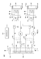
FIG. 1 depicts one embodiment of a conventional raised floor layout of an air-cooled data center;
FIG. 2A is an isometric view of one embodiment of a modular refrigeration unit (MRU) and its quick connects for attachment to a cold plate and/or evaporator disposed within an electronics rack to cool one or more electronic components (e.g., modules) thereof, in accordance with one or more aspects of the present invention;
FIG. 2B is a schematic of one embodiment of a vapor-compression refrigeration system for cooling an evaporator (or cold plate) coupled to a high heat flux electronic component (e.g., module) to be cooled, in accordance with one or more aspects of the present invention;
FIG. 3 is an schematic of an alternate embodiment of a vapor-compression refrigeration system for cooling one or more evaporators coupled to respective electronic components to be cooled, in accordance with one or more aspects of the present invention;
FIG. 4 is a schematic of another embodiment of a vapor-compression refrigeration system for cooling evaporator(s) coupled to one or more respective electronic components to be cooled, and employing contaminant cold trap(s), in accordance with one or more aspects of the present invention; and
FIG. 5 depicts one embodiment of a contaminant cold trap for a vapor-compression refrigeration system, in accordance with one or more aspects aspect of the present invention;
FIG. 6 is a schematic of another embodiment of a vapor compression refrigeration system for cooling one or more evaporators coupled to one or more respective electronic components to be cooled, and employing a contaminant extractor(s), in accordance with one or more aspects of the present invention;
FIG. 7 depicts one embodiment of a contaminant extractor for the vapor compression refrigeration system of FIG. 6, in accordance with one or more aspects of the present invention;
FIG. 8 is a schematic of another embodiment of a vapor compression refrigeration system for cooling one or more evaporators coupled to one or more respective electronic components to be cooled and employing a contaminant separator(s), in accordance with one or more aspects of the present invention;
FIG. 9 depicts one embodiment of a contaminant separator for the vapor compression refrigeration system of FIG. 8, in accordance with one or more aspects of the present invention;
FIG. 10 is a cross-sectional elevational view of one embodiment of the contaminant separator of the vapor-compression refrigeration system of FIG. 8, and shown comprising a thermoelectric-enhanced fluid-to-fluid heat exchange assembly, in accordance with one or more aspects of the present invention; and
FIG. 11 depicts an alternate embodiment of a contaminant separator for a vapor compression refrigeration system, in accordance with one or more aspects of the present invention.
DETAILED DESCRIPTION
As used herein, the terms “electronics rack”, “rack-mounted electronic equipment”, and “rack unit” are used interchangeably, and unless otherwise specified include any housing, frame, rack, compartment, blade server system, etc., having one or more heat generating components of a computer system or electronics system, and may be, for example, a stand alone computer processor having high, mid or low end processing capability. In one embodiment, an electronics rack may comprise an IT rack with multiple electronic subsystems, each having one or more heat generating components disposed therein requiring cooling. “Electronic subsystem” refers to any sub-housing, blade, book, drawer, node, compartment, etc., having one or more heat generating electronic components disposed therein. Each electronic subsystem of an electronics rack may be movable or fixed relative to the electronics rack, with rack-mounted electronics drawers of a multi-drawer rack unit and blades of a blade center system being two examples of subsystems of an electronics rack to be cooled.
“Electronic component” refers to any heat generating electronic component or module of, for example, a computer system or other electronic unit requiring cooling. By way of example, an electronic component may comprise one or more integrated circuit dies and/or other electronic devices to be cooled, including one or more processor dies, memory dies and memory support dies. As a further example, the electronic component may comprise one or more bare dies or one or more packaged dies disposed on a common carrier. Further, unless otherwise specified herein, the term “liquid-cooled cold plate” or “coolant-cooled structure” refers to any thermally conductive structure having a plurality of channels (or passageways) formed therein for flowing of coolant therethrough. A “coolant-cooled structure” may function, in one example, as a refrigerant evaporator.
As used herein, “refrigerant-to-air heat exchanger” means any heat exchange mechanism characterized as described herein through which refrigerant coolant can circulate; and includes, one or more discrete refrigerant-to-air heat exchangers coupled either in series or in parallel. A refrigerant-to-air heat exchanger may comprise, for example, one or more coolant flow paths, formed of thermally conductive tubing (such as copper or other tubing) in thermal or mechanical contact with a plurality of air-cooled cooling or condensing fins. Size, configuration and construction of the refrigerant-to-air heat exchanger can vary without departing from the scope of the invention disclosed herein.
Unless otherwise specified, “refrigerant evaporator” refers to a heat-absorbing mechanism or structure within a refrigeration loop. The refrigerant evaporator is alternatively referred to as a “sub-ambient evaporator” when temperature of the refrigerant passing through the refrigerant evaporator is below the temperature of ambient air entering the electronics rack. In one example, the refrigerant evaporator comprises a coolant-to-refrigerant heat exchanger. Within the refrigerant evaporator, heat is absorbed by evaporating the refrigerant of the refrigerant loop. Still further, “data center” refers to a computer installation containing one or more electronics racks to be cooled. As a specific example, a data center may include one or more rows of rack-mounted computing units, such as server units.
As used herein, the phrase “controllable thermoelectric array” refers to an adjustable thermoelectric array which allows active control of an auxiliary heat load applied to refrigerant passing through the refrigerant loop of a cooling apparatus, in a manner as described herein. In one example, the controllable thermoelectric array comprises one or more thermoelectric modules, each comprising one or more thermoelectric elements, coupled in thermal communication with the refrigerant passing through the compressor and powered by an electrical power source.
One example of the refrigerant employed in the examples below is R134a refrigerant. However, the concepts disclosed herein are readily adapted to use with other types of refrigerant. For example, R245fa, R404, R12, or R22 refrigerant may be employed.
Reference is made below to the drawings, which are not drawn to scale for ease of understanding, wherein the same reference numbers used throughout different figures designate the same or similar components.
FIG. 1 depicts a raised floor layout of an air cooled data center 100 typical in the prior art, wherein multiple electronics racks 110 are disposed in one or more rows. A data center such as depicted in FIG. 1 may house several hundred, or even several thousand microprocessors. In the arrangement illustrated, chilled air enters the computer room via perforated floor tiles 160 from a supply air plenum 145 defined between the raised floor 140 and a base or sub-floor 165 of the room. Cooled air is taken in through louvered or screened doors at air inlet sides 120 of the electronics racks and expelled through the back (i.e., air outlet sides 130) of the electronics racks. Each electronics rack 110 may have one or more air moving devices (e.g., fans or blowers) to provide forced inlet-to-outlet airflow to cool the electronic components within the drawer(s) of the rack. The supply air plenum 145 provides conditioned and cooled air to the air-inlet sides of the electronics racks via perforated floor tiles 160 disposed in a “cold” aisle of the computer installation. The conditioned and cooled air is supplied to plenum 145 by one or more air conditioning units 150, also disposed within the data center 100. Room air is taken into each air conditioning unit 150 near an upper portion thereof. This room air comprises in part exhausted air from the “hot” aisles of the computer installation defined by opposing air outlet sides 130 of the electronics racks 110.
In high performance server systems, it has become desirable to supplement air-cooling of selected high heat flux electronic components, such as the processor modules, within the electronics rack. For example, the System Z® server marketed by International Business Machines Corporation, of Armonk, N.Y., employs a vapor-compression refrigeration cooling system to facilitate cooling of the processor modules within the electronics rack. This refrigeration system employs R134a refrigerant as the coolant, which is supplied to a refrigerant evaporator coupled to one or more processor modules to be cooled. The refrigerant is provided by a modular refrigeration unit (MRU), which supplies the refrigerant at an appropriate temperature.
FIG. 2A depicts one embodiment of a modular refrigeration unit 200, which may be employed within an electronics rack, in accordance with an aspect of the present invention. As illustrated, modular refrigeration unit 200 includes refrigerant supply and exhaust hoses 201 for coupling to a refrigerant evaporator or cold plate (not shown), as well as quick connect couplings 202, which respectively connect to corresponding quick connect couplings on either side of the refrigerant evaporator, that is coupled to the electronic component(s) or module(s) (e.g., server module(s)) to be cooled. Further details of a modular refrigeration unit such as depicted in FIG. 2A are provided in commonly assigned U.S. Pat. No. 5,970,731.
FIG. 2B is a schematic of one embodiment of modular refrigeration unit 200 of FIG. 2A, coupled to a refrigerant evaporator for cooling, for example, an electronic component within an electronic subsystem of an electronics rack. The electronic component may comprise, for example, a multichip module, a processor module, or any other high heat flux electronic component (not shown) within the electronics rack. As illustrated in FIG. 2B, a refrigerant evaporator 260 is shown that is coupled to the electronic component (not shown) to be cooled and is connected to modular refrigeration unit 200 via respective quick connect couplings 202. Within modular refrigeration unit 200, a motor 221 drives a compressor 220, which is connected to a condenser 230 by means of a supply line 222. Likewise, condenser 230 is connected to evaporator 260 by means of a supply line which passes through a filter/dryer 240, which functions to trap particulate matter present in the refrigerant stream and also to remove any water which may have become entrained in the refrigerant flow. Subsequent to filter/dryer 240, refrigerant flow passes through an expansion device 250. Expansion device 250 may be an expansion valve. However, it may also comprise a capillary tube or thermostatic valve. Thus, expanded and cooled refrigerant is supplied to evaporator 260. Subsequent to the refrigerant picking up heat from the electronic component coupled to evaporator 260, the refrigerant is returned via an accumulator 210 which operates to prevent liquid from entering compressor 220. Accumulator 210 is also aided in this function by the inclusion of a smaller capacity accumulator 211, which is included to provide an extra degree of protection against the entry of liquid-phase refrigerant into compressor 220. Subsequent to accumulator 210, vapor-phase refrigerant is returned to compressor 220, where the cycle repeats. In addition, the modular refrigeration unit is provided with a hot gas bypass valve 225 in a bypass line 223 selectively passing hot refrigerant gasses from compressor 220 directly to evaporator 260. The hot gas bypass valve is controllable in response to the temperature of evaporator 260, which is provided by a module temperature sensor (not shown), such as a thermistor device affixed to the evaporator/cold plate in any convenient location. In one embodiment, the hot gas bypass valve is electronically controlled to shunt hot gas directly to the evaporator when temperature is already sufficiently low. In particular, under low temperature conditions, motor 221 runs at a lower speed in response to the reduced thermal load. At these lower speeds and loads, there is a risk of motor 221 stalling. Upon detection of such a condition, the hot gas bypass valve is opened in response to a signal supplied to it from a controller of the modular refrigeration unit.
FIG. 3 depicts an alternate embodiment of a modular refrigeration unit 300, which may be employed within an electronics rack, in accordance with an aspect of the present invention. Modular refrigeration unit 300 includes (in this example) two refrigerant loops 305, including sets of refrigerant supply and exhaust hoses, coupled to respective refrigerant evaporators (or cold plates) 360 via quick connect couplings 302. Each refrigerant evaporator 360 is in thermal communication with a respective electronic component 301 (e.g., multichip module (MCM)) for facilitating cooling thereof. Refrigerant loops 305 are independent, and shown to include a compressor 320, a respective condenser section of a shared condenser 330 (i.e., a refrigerant-to-air heat exchanger with an associated air-moving device), and an expansion (and flow control) valve 350, which is employed to maintain temperature of the electronic component at a steady temperature level, e.g., 29° C. In one embodiment, the expansion valves 350 are controlled by the controller 340 based on the temperature of the respective electronic component 301 TMCM1, TMCM2. The refrigerant and coolant loops may also contain further sensors, such as sensors for condenser air temperature in T1, condenser air temperature out T2, temperature T3, T3′ of high-pressure liquid refrigerant flowing from the condenser 330 to the respective expansion valve 350, temperature T4, T4′ of high-pressure refrigerant vapor flowing from each compressor 320 to the respective condenser section 330, temperature T6, T6′ of low-pressure liquid refrigerant flowing from each expansion valve 350 into the respective evaporator 360, and temperature T7, T7′ of low-pressure vapor refrigerant flowing from the respective evaporator 360 towards the compressor 320. Note that in this implementation, the expansion valves 350 operate to actively throttle the pumped refrigerant flow rate, as well as to function as expansion orifices to reduce the temperature and pressure of refrigerant passing through them. Note also that, in the embodiment depicted, refrigerant evaporators 360 further comprise a fixed orifice 361 integral with the respective evaporator. This fixed orifice functions as a second refrigerant expansion component, which provides a fixed expansion of the refrigerant at, for example, the inlet of the evaporator 360, to provide additional cooling of the refrigerant within the evaporator prior to absorbing heat from the respective electronic component 301.
In situations where electronic component 301 temperature decreases (i.e., the heat load decreases), the respective expansion valve 350 is partially closed to reduce the refrigerant flow passing through the associated evaporator 360 in an attempt to control temperature of the electronic component. If temperature of the component increases (i.e., heat load increases), then the controllable expansion valve 350 is opened further to allow more refrigerant flow to pass through the associated evaporator, thus providing increased cooling to the component.
In accordance with another aspect of the present invention, FIG. 4 depicts a variation of the cooling apparatus of FIG. 3, wherein a contaminant cold trap is provided to facilitate removal of contaminants from refrigerant circulating through the refrigerant loop (or refrigerant flow path). In the embodiment of FIG. 4, a dual loop, cooled electronic system is depicted by way of example. However, those skilled in the art should note that the cooling apparatus depicted therein and described below can be readily configured as a single loop or other multi-loop system for cooling a single electronic component, or a plurality of electronic components (either with or without employing a shared condenser, as in the example of FIG. 4).
As described above, vapor-compression cycle refrigeration can be employed to cool electronic components, such as multichip modules, in electronics racks, such as main frame computers. The power variations in the multichip modules and energy efficiency concerns dictate that an electronic expansion valve (EEV) be employed to control the mass flow rate of refrigerant to the evaporator, which as noted above, is conduction coupled to the electronic component (e.g., MCM). Control of the MCM temperature within a desired band is achieved by manipulating the refrigerant flow rate via the EEV. The refrigerant, in practice, is supplemented by a lubricating oil for the compressor, and passes through fittings containing O-rings, and through a filter/dryer. These materials are somewhat mutually soluble, and thus may contaminate the refrigerant. In the EEV, and any other expansion component of the vapor-compression refrigeration loop, the thermodynamic state of the refrigerant and the contaminant mixture is altered, and the contaminants may come out of solution on working components of the system, such as the EEV internal surfaces.
Specifically, it has been discovered that material can agglomerate in certain pressure drop areas of the expansion structures within the refrigeration system. During refrigerant-oil mixture transport, certain impurities and chemically reacted byproducts may come out of solution in the pressure drop areas as the refrigerant cools down. By way of example, an expansion valve may include a first element having an expansion orifice, and a second element having a tapered expansion pin. The expansion pin controls the amount of refrigerant passing through the expansion orifice, through which refrigerant flows. For the cooling applications described hereinabove, the expansion pin is stepped open in very small increments to allow controlled flow of refrigerant through expansion orifice into a pressure drop area of the expansion device.
During refrigerant-oil mixture transport through a hot compressor, any long-chain molecules and other typically non-soluble compounds at room temperature can go into solution in the hot mixture. These, as well as other physically transported impurities, then fall out of the solution when the refrigerant-oil mixture cools down, for example, in the pressure drop areas of the expansion structure. A layer of “waxy” material can build up in the pressure drop areas and act as a sticky substance which then catches other impurities. This amassing of material can interfere with the normal control expansion volumes and interfere with the control of motor steps (e.g., due to unpredictable valve characteristic changes). This is particularly true in a vapor compression refrigeration system employed as described above since the control of the expansion valves in this implementation is very sensitive and refrigerant expansion structure geometries are typically very small.
One solution to the problem is depicted in FIG. 4. As noted, cooling apparatus 300′ depicted in FIG. 4 is substantially identical to cooling apparatus 300 described above in connection with FIG. 3, with the shared condenser embodiment being depicted by way of example only. The concepts disclosed herein are readily applicable to a cooling apparatus comprising a vapor-compression refrigeration system which embodies a single vapor-compression refrigeration loop configured to facilitate cooling of one or more electronic components coupled to one or more evaporators within the loop.
As noted, cooling apparatus 300′ comprises a contaminant cold trap 400, which is coupled in fluid communication with the refrigerant loop (or refrigerant flow path) 305 of the vapor-compression refrigeration system, for example, between condenser 330 and expansion valve 350. The contaminant cold trap includes a refrigerant cold filter, and a coolant-cooled structure. At least a portion of refrigerant passing through the refrigerant flow path passes through the refrigerant cold filter, and the coolant-cooled structure provides cooling to the refrigerant cold filter to cool refrigerant passing through the refrigerant cold filter. Cooling of the refrigerant in the refrigerant cold filter allows contaminants to come out of solution (or solidify) from the refrigerant due to the cooling of the refrigerant, and thus, facilitates deposition of the contaminants within the refrigerant cold filter.
FIG. 4 illustrates one embodiment for cooling the coolant-cooled structure portion of the contaminant cold trap 400, and thus, facilitate cooling of refrigerant (e.g., the high-pressure, liquid refrigerant from condenser 330) passing through the refrigerant cold filter of the contaminant cold trap. As illustrated, a refrigerant return path 410 is coupled in fluid communication (via a flow splitter 401) with the refrigerant flow path 305 downstream from refrigerant expansion component 350. Generally, approximately 10% or less of the expanded, low-pressure refrigerant in the refrigerant flow path downstream of expansion component 350, is provided via refrigerant return path 410 back to contaminant cold trap 400, and in particular, to the coolant-cooled structure disposed within the contaminant cold trap for facilitating cooling of the refrigerant passing through the refrigerant flow path 305 upstream from refrigerant expansion component 350.
In one embodiment, the coolant-cooled structure comprises a second (or auxiliary) refrigerant evaporator, within which the portion of refrigerant provided via the refrigerant return path 410 boils to form low-pressure refrigerant vapor. A refrigerant bypass 420 is coupled in fluid communication between an outlet of the coolant-cooled structure and the refrigerant flow path 305 upstream of compressor 320, as illustrated in FIG. 4. By using a portion of the low-pressure refrigerant, downstream from the refrigerant expansion component (or valve) 350, to cool the coolant-cooled structure (i.e., auxiliary evaporator) within the contaminant cold trap, efficient cooling of the refrigerant cold filter is achieved. As one practical example, 3-5% of the low-pressure, liquid refrigerant downstream from expansion valve 350 may be provided back via the refrigerant return path 410 to the coolant-cooled structure of the contaminant cold trap to provide cooling to the refrigerant cold filter.
FIG. 5 depicts one embodiment of a portion of a cooling apparatus 500 comprising a contaminant cold trap 400 employed in a vapor-compression refrigeration system, such as the vapor-compression refrigeration system 300′ depicted in FIG. 4. As noted above, and as illustrated in FIG. 5, contaminant cold trap 400 includes a refrigerant cold filter 510 and a coolant-cooled structure 520. In the embodiment depicted, refrigerant cold filter 510 resides within a chamber 502 of a housing 501 of the contaminant cold trap, and is coupled in fluid communication with the refrigerant flow path 305, for example, upstream of the expansion valve 350 (see FIG. 4), between the condenser 330 and the expansion valve. In this location, high-pressure, liquid refrigerant flows through the refrigerant cold filter. By way of example, the refrigerant cold filter is a liquid-permeable structure which includes a plurality of thermally conductive surfaces across which the high-pressure, liquid refrigerant passes. The thermally conductive surfaces are configured and sized to facilitate cooling of the passing refrigerant and deposition of the solidifying contaminants onto the surfaces. Various liquid-permeable structure configurations may be employed, including, for example, a metal foam structure, metal mesh or screen, or an array of thermally conductive fins. For example, multiple sets of parallel fins 511 may be provided as a mesh structure, with openings 512 through which the refrigerant passes.
The extended, thermally conductive surfaces of the refrigerant cold filter 510 are cooled to, for example, a temperature below the temperature of the refrigerant within the expansion valve 350 (FIG. 3). By cooling the cold filter, the refrigerant passing through the cold filter is cooled, which allows contaminants in the refrigerant to solidify or precipitate out within the refrigerant cold filter, and to become deposited on one of the surfaces of the cold filter, rather than in a critical component, such as an adjustable expansion valve. As one example, the coolant-cooled structure 520 may be formed integral with housing 501 of contaminant cold trap 400, and be formed, for example, from a thermally conductive material. In one embodiment, the coolant-cooled structure may comprise an evaporator assembly with one or more flow boiling channels 521, through which the portion of refrigerant provided via refrigerant return path 410 flows. After boiling within the auxiliary evaporator (or coolant-cooled structure), the refrigerant is output as low-pressure vapor through the refrigerant bypass 420 for return, for example, to the refrigerant loop upstream of compressor 320 (see FIG. 4). In this embodiment, a further expansion component 530 is provided coupled in fluid communication with refrigerant return path 410 at the inlet to coolant-cooled structure 520 of contaminant cold trap 400. In one example, this auxiliary expansion component 530 may comprise a capillary tube or fixed expansion orifice, which provides further cooling of the portion of refrigerant returned to the contaminant cold trap to a temperature below the refrigerant temperature of the outlet of the expansion valve 350 (FIG. 4) to further enhance cooling of the refrigerant cold filter, and thus, the refrigerant passing through the cold filter.
Those skilled in the art will note that the contaminant cold trap disclosed herein advantageously facilitates solidifying contaminants from the working refrigerant in a designated region, i.e., the refrigerant cold filter. This designated region is provided to reduce adverse effects of the contaminants coming out of solution in more sensitive portions of the vapor-compression refrigeration system, such as, for example, within an expansion valve. Further, efficient cooling of the contaminant cold trap is achieved by using a portion of the refrigerant flow itself to cool the coolant-cooled structure of the cold trap.
In accordance with another aspect of the present invention, FIG. 6 depicts a variation of the cooling apparatus of FIG. 3, wherein a contaminant extractor is provided to facilitate removal of contaminants from refrigerant circulating through the refrigerant loop (or refrigerant flow path). In the embodiment of FIG. 6, a dual loop, cooled electronic system is depicted by way of example. However, those skilled in the art should note that the cooling apparatus depicted therein and described below can be readily configured as a single loop or other multi-loop system for cooling a single electronic component, or a plurality of electronic components (either with or without employing a shared condenser, as in the example of FIG. 6).
As described above, vapor-compression cycle refrigeration can be employed to cool electronic components, such as multichip modules, in electronics racks, such as main frame computers. The power variations in the multichip modules and energy efficiency concerns dictate that an electronic expansion valve (EEV) be employed to control the mass flow rate of refrigerant to the evaporator, which as noted above, is conduction coupled to the electronic component (e.g., MCM). Control of the MCM temperature within a desired band is achieved by manipulating the refrigerant flow rate via the EEV. The refrigerant, in practice, is supplemented by a lubricating oil for the compressor, and passes through fittings containing O-rings, and through a filter/dryer. These materials are somewhat mutually soluble, and thus may contaminate the refrigerant. In the EEV, and any other expansion component of the vapor-compression refrigeration loop, the thermodynamic state of the refrigerant and the contaminant mixture is altered, and the contaminants may come out of solution on working components of the system, such as the EEV internal surfaces.
Specifically, with relevance to the embodiment of FIG. 6, it has been discovered that material can become deposited within the evaporator due to boiling of refrigerant within the evaporator, which could affect operation of the evaporator over time.
One solution to the problem is depicted in FIG. 6. As noted, cooling apparatus 300″ depicted in FIG. 6 is substantially identical to cooling apparatus 300 described above in connection with FIG. 3, with the shared condenser embodiment being depicted by way of example only. The concepts disclosed herein are readily applicable to a cooling apparatus comprising a vapor-compression refrigeration system which embodies a single vapor-compression refrigeration loop configured to facilitate cooling of one or more electronic components coupled to one or more evaporators within the loop.
As noted, cooling apparatus 300″ comprises a contaminant extractor 600, which is (in one embodiment) an intra-condenser extractor coupled in fluid communication with the section of the refrigerant loop (or refrigerant flow path) 305 of the vapor-compression refrigeration system that passes through the condenser 330. The contaminant extractor includes a refrigerant boiling filter and a heater. At least a portion of refrigerant passing through the refrigerant flow path passes through the refrigerant boiling filter, and the heater provides heat to the refrigerant boiling filter to boil refrigerant passing through the refrigerant boiling filter. Boiling of the refrigerant in the refrigerant boiling filter allows contaminants to come out of solution (or distill) from the refrigerant due to the boiling of the refrigerant, and thus, facilitates deposition of the contaminants within the refrigerant boiling filter.
FIG. 6 illustrates one implementation of a cooling apparatus comprising an intra-condenser contaminant extractor 600, which is coupled in parallel with a portion of the tubing within condenser 330. In particular, in one implementation, the intra-condenser contaminant extractor is coupled to the condenser 330 at a location within the condenser where the refrigerant comprises a liquid-gas mixture. A portion of this liquid-gas mixture enters the contaminant extractor, which as noted, includes a heater which boils the liquid refrigerant completely, causing any contaminants in the liquid-gas mixture to be extracted (or plated out) onto the surfaces of the extractor at any one time. In one example, less than approximately 25% of the refrigerant passing within the refrigerant flow path within the condenser is directed through the contaminant extractor. In one specific implementation, 10-25% of the refrigerant passing through the condenser is directed through the contaminant extractor. This can be achieved by providing tubing directing a portion of the refrigerant passing through the condenser to also pass through the contaminant extractor. After passing through the contaminant extractor, the high-pressure refrigerant vapor is returned to the condenser for condensing into high-pressure liquid refrigerant for return via the refrigerant flow path to the one or more expansion devices and the evaporator.
Those skilled in the art will note that the contaminant extractor described herein can be disposed in various places within the vapor-compression refrigeration loop. However, by coupling the contaminant extractor in parallel fluid communication with a portion of the refrigerant flow path passing through the condenser, less heat is required in order to boil the portion of refrigerant passing through the filter, and thus, to extract any contaminants within that portion of the refrigerant. During sequential vapor-compression cycles, contaminants are cleaned from the refrigerant by boiling and filtering of the contaminants within the contaminant extractor. The contaminant extractor is advantageously positioned in the refrigerant stream after the compressor and before the expansion device(s) to remove contaminants that may be introduced within the compressor to prevent the contaminants from reaching the expansion device(s) and evaporator.
FIG. 7 depicts one embodiment of a contaminant extractor 600 to be employed in a vapor-compression refrigeration system, such as the vapor-compression refrigeration system 300″ depicted in FIG. 6. As noted above, and as illustrated in FIG. 7, contaminant extractor 600 includes a refrigerant boiling filter 710 and a heater 720. In the embodiment depicted, refrigerant boiling filter 710 resides within a chamber 702 of a housing 701 of the contaminant extractor, and is coupled in fluid communication with the refrigerant flow path 305, for example, midstream of the condenser 330 (see FIG. 6). In this location, a high-pressure liquid-gas refrigerant mixture is directed through the refrigerant boiling filter. Tubing and filter structures of the contaminant extractor are sized to allow a desired portion of the refrigerant flow to be diverted from the condenser through the filter, and a flow restriction such as an orifice or section of small diameter tubing may be used in the refrigerant path through the condenser in a parallel fluid flow to the contaminant extractor to further control the ratio of refrigerant flow that passes through the filter.
By way of example, the refrigerant boiling filter is a fluid-permeable structure which includes a plurality of thermally conductive surfaces across which the high-pressure, liquid gas refrigerant passes. The thermally conductive surfaces are configured and sized to facilitate boiling of the passing refrigeration and deposition of the extracted contaminants onto the surfaces of the filter. Various fluid-permeable structure configurations may be employed, including, for example, a metal foam structure, metal mesh or screen, or an array of thermally conductive fins. For example, multiple sets of parallel fins 711 may be provided as a mesh structure, with openings 712 through which the refrigerant passes.
The extended, thermally conductive surfaces of the refrigerant boiling filter 710 are heated to, for example, a temperature above the boiling temperature of the refrigerant within the condenser 330 (FIG. 6). By heating the boiling filter, the refrigerant passing through the boiling filter is heated, which allows contaminants in the refrigerant to come out of solution within the refrigerant boiling filter, and to become deposited on one of the surfaces of the boiling filter, rather than in a critical component, such as an adjustable expansion valve. As one example, the heater 720 may be a resistive-type heater thermally coupled to housing 701 of contaminant extractor 600, and be formed of or reside in, for example, a thermally conductive material. After boiling within the extractor, the refrigerant is output as high-pressure vapor for return to the condenser 330 (FIG. 6).
In addition to the above-described contaminant extractor, adsorption is an alternative (or additional) filtering approach, which may assist in removing impurities from refrigerant before reaching the one or more expansion devices. In the case of adsorption purification, the high-pressure refrigerant and impurity vapor mixture exiting the compressor is flowed through an in-line container 610 installed in fluid communication with the refrigerant flow path before condenser 330, as illustrated in FIG. 6. This in-line container 610 may comprise solid grains or a mesh, to which the impurity preferentially adsorbs. Thus, the gas mixture leaving the adsorption purifier is comparatively pure and can be condensed and used in the refrigeration cycle. In one embodiment, the adsorption chamber 610 would need to be occasionally replaced or regenerated.
Those skilled in the art will note that the contaminant extractor disclosed herein advantageously facilitates removal of contaminants from the working refrigerant in a designated region, i.e., the refrigerant boiling filter. This designated region is provided to reduce adverse effects of the contaminants coming out of solution in more sensitive portions of the vapor-compression refrigeration system, such as, for example, within an expansion valve. Further, efficient heating by the contaminant extractor is achieved by passing a portion of the refrigerant flow within the condenser through the boiling filter.
In accordance with another aspect of the present invention, FIG. 8 depicts a variation of the cooling apparatuses of FIGS. 3-7, wherein a contaminant separator is provided to facilitate removal of contaminants from refrigerant circulating through the refrigerant loop (or refrigerant flow path). In the embodiment of FIG. 8, a dual loop, cooled electronic system is again depicted by way of example only. Those skilled in the art will note that the cooling apparatus depicted therein and described below can be readily configured as a single loop or other multi-loop system for cooling a single electronic component, or a plurality of electronic components (either with or without employing a shared condenser, as in the examples of FIGS. 4 & 6).
As depicted in FIG. 8, cooled electronic system 800 is substantially identical to the cooled electronic systems and cooling apparatuses described above in connection with FIGS. 3-7. In this embodiment, however, cooled electronic system 800 includes a contaminant separator 810, which in one embodiment, comprises a refrigerant cold trap 812, a thermoelectric array 811 and a contaminant extractor 813, with the thermoelectric array being disposed between the refrigerant cold trap 812 and the refrigerant extractor 813 to facilitate cooling of refrigerant passing through the refrigerant cold trap, and heating of liquid refrigerant passing through the refrigerant extractor 813. Controller 340 controls the electrical current supplied by a DC power supply 820 to thermoelectric array 811 to control the heat transfer process within the contaminant separator. As illustrated, contaminant extractor 813 is disposed in a refrigerant line 801 coupled in fluid communication with and parallel to at least a portion of the refrigerant flow path through the condenser 330. In one embodiment, the refrigerant cold trap 812 comprises a refrigerant cold trap such as described above in connection with the apparatus of FIGS. 4-5, and the refrigerant extractor comprises a refrigerant boiling filter such as described above in connection with the apparatus of FIGS. 6-7.
In operation, the thermoelectric array pumps heat from a cold side to a hot side when an electrical current is applied. The contaminant separator which is coupled in fluid communication with the refrigerant flow path 305, receives a high pressure liquid refrigerant flow from upstream of the refrigerant expansion device 350, and passes at least a portion of the refrigerant flow through the refrigerant cold trap 812 for removing contaminants solidifying from the refrigerant due to cooling of the refrigerant in the refrigerant cold filter. In this embodiment, the refrigerant cold trap is thermally coupled to the cold side of the thermoelectric array, and exhausts high pressure liquid refrigerant to the refrigerant expansion device 350. The contaminant separator also receives (through refrigerant line 801) a high pressure liquid-vapor mixture diverted from the condenser 330, which is passed through contaminant extractor 813. Contaminant extractor 813 is thermally coupled to the hot side of the thermoelectric array 811 for preferentially accumulating contaminants in the refrigerant hot filter of the contaminant extractor rather than letting the contaminants continue to circulate to the refrigerant expansion device and evaporator. The refrigerant extractor exhausts high pressure vapor refrigerant back to the condenser flow path, as illustrated in FIG. 8.
FIG. 9 depicts one embodiment of contaminant separator 810 for a vapor compression refrigeration system, such as the vapor-compression refrigeration system 800 depicted in FIG. 8. As noted above, and as illustrated in FIG. 9, contaminant separator 810 includes thermoelectric array 811, contaminant cold trap 812 and contaminant extractor 813. Contaminant cold trap 812 includes a refrigerant cold filter 900, which resides in a chamber 902 of a housing 901 of the contaminant cold trap, and is coupled in fluid communication with the refrigerant flow path 305, for example, upstream of expansion valve 350 (FIG. 8), between condenser 330 and the expansion valve. In this location, high pressure, liquid refrigerant flows through the refrigerant cold filter. By way of example, the refrigerant cold filter is a liquid-permeable structure which includes a plurality of thermally conductive surfaces across which the high pressure, liquid refrigerant passes. The thermally conductive surfaces are configured and sized to facilitate cooling of the passing refrigerant and deposition of the solidifying contaminants onto the surfaces. Various liquid-permeable structure configurations may be employed, including, for example, a metal foam structure, metal mesh or screen, or an array of thermally conductive fins. By way of example, multiple sets of parallel fins 903 may be provided as a mesh structure, with openings 904 through which the refrigerant passes.
The extended, thermally conductive surfaces of refrigerant cold filter 900 are cooled to, for example, a temperature below the temperature of the refrigerant within the expansion valve 350 (FIG. 8). By cooling the cold filter, the refrigerant passing through the cold filter is cooled, which allows contaminants in the refrigerant to solidify or precipitate out within the refrigerant cold filter and to become deposited on one or more surfaces of the cold filter, rather than a critical component, such as the adjustable expansion valve. As one example, the refrigerant cold trap 812, thermoelectric array 811 and refrigerant extractor 813 may be fabricated as a stacked structure, such as depicted in FIG. 9.
One embodiment of the thermoelectric array 811 of contaminant separator 810 is depicted in greater detail in FIG. 10. Note that in this example, the contaminant separator comprises a thermoelectric-enhanced, fluid-to-fluid heat exchange assembly. As illustrated in FIG. 10, thermoelectric array 811 comprises in one example, a plurality of thermoelectric modules 1000, each of which comprises individual thermoelectric elements 1001.
The use of large thermoelectric cooling elements is known. These elements operate electronically to produce a cooling effect. By passing a direct current through the legs of a thermoelectric device, a heat flow is produced across the device which may be contrary to that which would be expected from Fourier's law.
At one junction of the thermoelectric element, both holes and electrons move away, towards the other junction, as a consequence of the current flow through the junction. Holes move through the p-type material and electrons through the n-type material. To compensate for this loss of charge carriers, additional electrons are raised from the valence band to the conduction band to create new pairs of electrons and holes. Since energy is required to do this, heat is absorbed at this junction. Conversely, as an electron drops into a hole at the other junction, its surplus energy is released in the form of heat. This transfer of thermal energy from the cold junction to the hot junction is known as the Peltier effect.
Use of the Peltier effect permits the surfaces attached to a heat source to be maintained at a temperature below that of a surface attached to a heat sink. What these thermoelectric modules provide is the ability to operate the cold side below the ambient temperature of the cooling medium (e.g., air or water). When direct current is passed through the thermoelectric modules, a temperature difference is produced with the result that one side is relatively cooler than the other side. These thermoelectric modules are therefore seen to possess a hot side and a cold side, and provide a mechanism for facilitating the transfer of thermal energy from the cold side of the thermoelectric module to the hot side of the thermoelectric module.
By way of specific example, thermoelectric modules 1000 may comprise TEC CP-2-127-06L modules, offered by Melcor Laird, of Cleveland, Ohio.
Note that the thermoelectric array may comprise any number of thermoelectric modules, including one or more modules, and is dependent (in part) on the size of the cold trap and extractor, as well as the amount of heat to be transferred from refrigerant flowing through contaminant extractor 813, to refrigerant flowing through contaminant cold trap 812. Also note that an insulated material (not shown) may be provided over one or more of the exposed surfaces of refrigerant cold trap 812 or refrigerant extractor 813. As noted above, heat is transferred from refrigerant within the contaminant cold trap 812 to refrigerant within the refrigerant extractor 813. In operation, the amount of heat transferred to contaminant extractor 813 exceeds the amount of heat extracted from contaminant cold trap 812 by an amount equal to the losses in the thermoelectric modules 1000.
The thermoelectric (TE) array may comprise a planar thermoelectric array with modules arranged in a square or rectangular array. Although the wiring is not shown, each thermoelectric module in a column may be wired and supplied electric current (I) in series and the columns of thermoelectric modules may be electrically wired in parallel so that the total current supplied would be I×sqrt(M) for a square array comprising M thermoelectric modules, providing an appreciation of the inherent scalability of the array. In this way, if a single thermoelectric module should fail, only one column is effected, and electric current to the remaining columns may be increased to compensate for the failure.
Table 1 provides an example of the scalability provided by a planar thermoelectric heat exchanger configuration such as described herein.
TABLE 1
Number of TE
Modules (M) Heat Exchanger Size
81 585 mm × 585 mm
(23.0 in. × 23.0 in.)
100 650 mm × 650 mm
(25.6 in. × 25.6 in.)
121 715 mm × 715 mm
(28.2 in. × 28.2 in.)
144 780 mm × 780 mm
(30.7 in. × 30.7 in.)
169 845 mm × 845 mm
(33.3 in. × 33.3 in.)
For a fixed electric current and temperature difference across the thermoelectric modules, the heat pumped by the thermoelectric array will scale with the number of thermoelectric modules in the platform area. Thus, the heat load capability of a 650 mm×650 mm thermoelectric heat exchanger will be 1.23 times that of a 585 mm×585 mm thermoelectric heat exchanger, and that of an 845 mm×845 mm will be 2.09 times greater. Note that the size of the liquid-to-air heat exchanger may need to grow to accommodate the increased heat load from the thermoelectric arrays. If the space available for the thermoelectric heat exchanger is constrained in the X×Y dimensions, then the heat pumping capabilities can still be scaled upwards by growing in the Z dimension. This can be done by utilizing multiple layers of thermoelectric modules between multiple heat exchange elements, with alternating hot and cold sides, as described in the above-referenced U.S. Pat. No. 6,557,354 B1.
Returning to FIG. 9, contaminant extractor 813 is shown to include a refrigerant hot filter (or refrigerant boiling filter) 910. In one embodiment, the contaminant extractor 813 comprises an intra-condenser contaminant extractor wherein liquid-vapor refrigerant is redirected via refrigerant line 801 from within a portion of the condenser 330 (FIG. 8) to pass through contaminant extractor 813. Refrigerant hot filter 910 resides within a chamber 912 of a housing 911 of the contaminant extractor and is coupled in fluid communication with refrigerant line 801, which redirects refrigerant from, for example, midstream of condenser 330 (FIG. 8). In this location, high pressure liquid-gas refrigerant mixture is directed through the refrigerant boiling filter. Tubing and filter structures of the contaminant extractor are sized to allow a desired portion of the refrigerant flow to be diverted from the condenser through the filter, and a flow restrictor such as an orifice or section of a small diameter tubing may be used in the refrigerant path through the condenser in the parallel fluid flow to the contaminant extractor to further control the ratio of refrigerant flow that passes through the refrigerant hot filter 910.
By way of example, the refrigerant hot filter is a fluid-permeable structure which includes a plurality of thermally conductive surfaces across which the high pressure, liquid-gas refrigerant passes. The thermally conductive surfaces are configured and sized to facilitate boiling of the passing refrigerant and deposition of the extracted contaminants on the surfaces of the filter. Various fluid-permeable structure configurations may be employed, including, for example, a metal foam structure, metal mesh or screen structure or an array of thermally conductive fins. For example, multiple sets of parallel fins 913 may be provided as a mesh structure with openings 914 through which the refrigerant passes.
Contaminant extractor 813 is coupled to the hot side of the thermoelectric array 811, and the thermoelectric array 811 heats the thermally conductive surfaces of the refrigerant hot filter 910 to, for example, a temperature above the boiling temperature of the refrigerant within the condenser 330 (FIG. 8). By heating the boiling filter, the refrigerant passing through the boiling filter is heated, which allows contaminants in the refrigerant to come out of solution within the refrigerant boiling filter, and to become deposited on one of the surfaces of the boiling filter, rather than in a critical component such as an adjustable expansion valve or evaporator. As noted, commensurate with heating the refrigerant within contaminant extractor 813, thermoelectric array 811 cools refrigerant passing through contaminant cold trap 812. Thus, two different mechanisms for extracting contaminants from the refrigerant are simultaneously provided within contaminant separator 810. Within contaminant cold trap 812, contaminants solidifying from the refrigerant due to cooling of the refrigerant are deposited, while within contaminant extractor 813, contaminants extracted from the refrigerant due to boiling of the refrigerant are deposited.
FIG. 11 depicts an alternate embodiment of a contaminant separator 810′ for a cooled electronic system such as depicted in FIG. 8, in accordance with one or more aspects of the present invention. In this embodiment, contaminant separator 810′ comprises a stacked structure with thermoelectric array 811 disposed between contaminant cold trap 812 and contaminant extractor 813, as described above in connection with FIGS. 8-10. Additionally, a second thermoelectric array 1100 is disposed between contaminant extractor 813 and a heat exchange element 1110, with the hot side of the second thermoelectric array 1100 being in thermal contact with contaminant extractor 813, and the cold side being in thermal contact with the heat exchange element 1110. In one embodiment, second thermoelectric array 1100 is substantially identical to the above-described thermoelectric array 811. However, in an alternate embodiment, the thermoelectric arrays may be differently configured and/or sized to provide, for example, different amounts of thermoelectric heat pumping across the arrays. Further, both thermoelectric arrays are separately controllable by, for example, controller 340 of the cooled electronic system depicted in FIG. 8, with the same or different amounts of DC power being supplied to the different thermoelectric arrays, as desired (for example, to accomplish the contaminant extraction described herein). In the embodiment depicted of FIG. 11, a high pressure liquid-gas mixture is diverted from a mid-condenser flow path into the refrigerant boiling filter section of contaminant extractor 813 via refrigerant line 801. Contaminant extractor 813 is heated on two sides, by first thermoelectric array 811 and second thermoelectric array 1100, which facilitates boiling of liquid refrigerant passing through the refrigerant boiling filter of the contaminant extractor 813. Thus, in one embodiment, the first thermoelectric array 811 and second thermoelectric array 1100 are thermally coupled on their hot side to contaminant extractor 813, and on their cold side to contaminant cold trap 812, and heat exchange element 1110, respectively. Note that in one example, heat exchange element 1110 may comprise a structure similar to contaminant cold trap 812 or contaminant extractor 813. Such a configuration improves efficiency of the contaminant separator. However, in an alternate embodiment, the cold side of the second thermoelectric array 1100 may be attached to an independent heat sink, or to any component(s) within the refrigerant loop to be cooled (such as to control electronics, a compressor housing, etc.).
The terminology used herein is for the purpose of describing particular embodiments only and is not intended to be limiting of the invention. As used herein, the singular forms “a”, “an” and “the” are intended to include the plural forms as well, unless the context clearly indicates otherwise. It will be further understood that the terms “comprise” (and any form of comprise, such as “comprises” and “comprising”), “have” (and any form of have, such as “has” and “having”), “include” (and any form of include, such as “includes” and “including”), and “contain” (and any form contain, such as “contains” and “containing”) are open-ended linking verbs. As a result, a method or device that “comprises”, “has”, “includes” or “contains” one or more steps or elements possesses those one or more steps or elements, but is not limited to possessing only those one or more steps or elements. Likewise, a step of a method or an element of a device that “comprises”, “has”, “includes” or “contains” one or more features possesses those one or more features, but is not limited to possessing only those one or more features. Furthermore, a device or structure that is configured in a certain way is configured in at least that way, but may also be configured in ways that are not listed.
The corresponding structures, materials, acts, and equivalents of all means or step plus function elements in the claims below, if any, are intended to include any structure, material, or act for performing the function in combination with other claimed elements as specifically claimed. The description of the present invention has been presented for purposes of illustration and description, but is not intended to be exhaustive or limited to the invention in the form disclosed. Many modifications and variations will be apparent to those of ordinary skill in the art without departing from the scope and spirit of the invention.

Claims (16)

What is claimed is:
1. An apparatus for facilitating cooling of an electronic component, the apparatus comprising:
a vapor-compression refrigeration system comprising a refrigerant expansion component, a refrigerant evaporator, a compressor and a condenser coupled in fluid communication to define a refrigerant flow path and allow the flow of refrigerant therethrough, the refrigerant evaporator being configured to couple to the electronic component; and
a contaminant separator coupled in fluid communication with the refrigerant flow path, the contaminant separator including:
a first filter and a second filter, the first filter and the second filter being coupled to the refrigerant flow path at different locations along the refrigerant flow path, wherein at least a portion of refrigerant passing through the refrigerant flow path passes through the first filter and passes through the second filter, the first filter being a cooling filter cooling the refrigerant passing therethrough, and the second filter being a heating filter heating the refrigerant passing therethrough;
a first thermoelectric array comprising at least one thermoelectric module, the first thermoelectric array being coupled at a first side to the first filter and at a second side to the second filter, and providing cooling to the first filter to cool refrigerant passing through the first filter, and facilitate deposition in the first filter of contaminants solidifying from the refrigerant due to cooling of the refrigerant in the first filter, and providing heating to the second filter to heat refrigerant passing through the second filter, and facilitate deposition in the second filter of contaminants extracted from the refrigerant by heating of the refrigerant in the second filter; and
a second thermoelectric array and a heat exchange element, the heat exchange element being coupled in fluid communication with the refrigerant flow path, and the second thermoelectric array being thermally coupled between the second filter and the heat exchange element for providing heat to the second filter to facilitate boiling of refrigerant passing through the second filter, wherein the second filter is coupled to a first side of the second thermoelectric array, and the heat exchange element is coupled to a second side of the second thermoelectric array.
2. The apparatus of claim 1, wherein the first filter is coupled in fluid communication with the refrigerant flow path upstream of the refrigerant expansion component.
3. The apparatus of claim 1, wherein the second filter comprises a refrigerant boiling filter to boil refrigerant passing through the refrigerant boiling filter, and facilitate deposition in the refrigerant boiling filter of contaminants extracted from the refrigerant due to boiling of the refrigerant in the refrigerant boiling filter.
4. The apparatus of claim 1, wherein the second filter is coupled in fluid communication with and parallel to at least a portion of a refrigerant path through the condenser.
5. The apparatus of claim 1, wherein the first filter comprises a liquid-permeable structure which includes thermally conductive surfaces across which refrigerant passing through the contaminant separator flows, and wherein the first thermoelectric array provides conduction cooling to the thermally conductive surfaces of the liquid-permeable structure across which the refrigerant flows to facilitate contaminants solidifying from the refrigerant due to cooling of the refrigerant.
6. The apparatus of claim 1, wherein the second filter comprises a fluid-permeable structure which includes thermally conductive surfaces across which the refrigerant passing through the second filter passes, and wherein the first thermoelectric array heats the thermally conductive surfaces of the fluid-permeable structure of the second filter across which the refrigerant passes to facilitate boiling of liquid refrigerant and extracting of contaminants from the refrigerant due to heating of the refrigerant.
7. The apparatus of claim 6, wherein the first filter comprises one of a metal foam structure, metal mesh or screen structure, or an array of thermally conductive fins, and wherein the second filter comprises one of a metal foam structure, metal mesh or screen structure, or an array of thermally conductive fins.
8. The apparatus of claim 1, wherein the first thermoelectric array and the second thermoelectric array are separately controllable to facilitate control, in part, of heat being applied to the second filter.
9. A cooled electronic system comprising:
at least one heat generating electronic component;
a vapor-compression refrigerant system coupled to the at least one heat generating electronic component, the vapor compression refrigeration system including:
a refrigerant expansion component;
a refrigerator evaporator, the refrigerant evaporator being coupled to the at least one heating generating electronic component;
a compressor; and
a condenser;
a refrigerant flow path coupling in fluid communication with the refrigerant expansion component, the refrigerant evaporator, the compressor and the condenser; and
a contaminant separator coupled in fluid communication with the refrigerant flow path, the contaminant separator including:
a first filter and a second filter, the first filter and the second filter being coupled to the refrigerant flow path at different locations along the refrigerant flow path, wherein at least a portion of refrigerant passing through the refrigerant flow path passes through the first filter and passes through the second filter, the first filter being a cooling filter cooling the refrigerant passing therethrough, and the second filter being a heating filter heating the refrigerant passing therethrough;
a first thermoelectric array comprising at least one thermoelectric module, the first thermoelectric array being coupled at a first side to the first filter and at a second side to the second filter, and providing cooling to the first filter to cool refrigerant passing through the first filter, and facilitate deposition in the first filter of contaminants solidifying from the refrigerant due to cooling of the refrigerant in the first filter, and providing heating to the second filter to heat refrigerant passing through the second filter, and facilitate deposition in the second filter of contaminants extracted from the refrigerant by heating of the refrigerant in the second filter; and
a second thermoelectric array and a heat exchange element, the heat exchange element being coupled in fluid communication with the refrigerant flow path, and the second thermoelectric array being thermally coupled between the second filter and the heat exchange element for providing heat to the second filter to facilitate boiling of refrigerant passing through the second filter, wherein the second filter is coupled to a first side of the second thermoelectric array, and the heat exchange element is coupled to a second side of the second thermoelectric array.
10. The cooled electronic system of claim 9, wherein the first filter is coupled in fluid communication with the refrigerant flow path upstream of the refrigerant expansion component.
11. The cooled electronic system of claim 9, wherein the second filter comprises a refrigerant boiling filter to boil refrigerant passing through the refrigerant boiling filter, and facilitate deposition in the refrigerant boiling filter of contaminants extracted from the refrigerant due to boiling of the refrigerant in the refrigerant boiling filter.
12. The cooled electronic system of claim 9, wherein the second filter is coupled in fluid communication with and parallel to at least a portion of a refrigerant path through the condenser.
13. The cooled electronic system of claim 9, wherein the first filter comprises a liquid-permeable structure which includes thermally conductive surfaces across which refrigerant passing through the contaminant separator flows, and wherein the first thermoelectric array provides conduction cooling to the thermally conductive surfaces of the liquid-permeable structure across which the refrigerant flows to facilitate contaminants solidifying from the refrigerant due to cooling of the refrigerant.
14. The cooled electronic system of claim 13, wherein the second filter comprises a fluid-permeable structure which includes thermally conductive surfaces across which the refrigerant passing through the second filter passes, and wherein the first thermoelectric array heats the thermally conductive surfaces of the fluid-permeable structure of the second filter across which the refrigerant passes to facilitate boiling of liquid refrigerant and extracting of contaminants from the refrigerant due to heating of the refrigerant.
15. The cooled electronic system of claim 14, wherein the first filter comprises one of a metal foam structure, metal mesh or screen structure, or an array of thermally conductive fins, and wherein the second filter comprises one of a metal foam structure, metal mesh or screen structure, or an array of thermally conductive fins.
16. A method of fabricating a vapor-compression refrigeration system for cooling at least one heating generating electronic component, the method comprising:
providing a condenser, a refrigerant expansion structure, a refrigerant evaporator, and a compressor;
coupling a condenser, refrigerant expansion structure, refrigerant evaporator and compressor in fluid communication to define a refrigerant flow path;
providing a contaminant separator in fluid communication with the refrigerant flow path, the contaminant separator including:
a first filter and a second filter, the first filter and the second filter being coupled to the refrigerant flow path at different locations along the refrigerant flow path, wherein at least a portion of refrigerant passing through the refrigerant flow path passes through the first filter and passes through the second filter, the first filter being a cooling filter cooling the refrigerant passing therethrough, and the second filter being a heating filter heating the refrigerant passing therethrough;
a first thermoelectric array comprising at least one thermoelectric module, the first thermoelectric array being coupled at a first side to the first filter and at a second side to the second filter, and providing cooling to the first filter to cool refrigerant passing through the first filter, and facilitate deposition in the first filter of contaminants solidifying from the refrigerant due to cooling of the refrigerant in the first filter, and providing heating to the second filter to heat refrigerant passing through the second filter, and facilitate deposition in the second filter of contaminants extracted from the refrigerant by heating of the refrigerant in the second filter; and
a second thermoelectric array and a heat exchange element, the heat exchange element being coupled in fluid communication with the refrigerant flow path, and the second thermoelectric array being thermally coupled between the second filter and the heat exchange element for providing heat to the second filter to facilitate boiling of refrigerant passing through the second filter, wherein the second refrigerant hot filter is coupled to a first side of the second thermoelectric array, and the heat exchange element is coupled to a second side of the second thermoelectric array; and
providing refrigerant within the refrigerant flow path of the vapor-compression refrigeration system to allow for cooling of the at least one heat-generating electronic component, wherein the contaminant separator removes contaminants from the refrigerant commensurate with cooling of the at least one heat-generating electronic component.
US14/066,769 2011-10-12 2013-10-30 Contaminant separator for a vapor-compression refrigeration apparatus Expired - Fee Related US9470439B2 (en)

Priority Applications (1)

Application Number Priority Date Filing Date Title
US14/066,769 US9470439B2 (en) 2011-10-12 2013-10-30 Contaminant separator for a vapor-compression refrigeration apparatus

Applications Claiming Priority (2)

Application Number Priority Date Filing Date Title
US13/271,304 US9207002B2 (en) 2011-10-12 2011-10-12 Contaminant separator for a vapor-compression refrigeration apparatus
US14/066,769 US9470439B2 (en) 2011-10-12 2013-10-30 Contaminant separator for a vapor-compression refrigeration apparatus

Related Parent Applications (1)

Application Number Title Priority Date Filing Date
US13/271,304 Division US9207002B2 (en) 2011-10-12 2011-10-12 Contaminant separator for a vapor-compression refrigeration apparatus

Publications (2)

Publication Number Publication Date
US20140053575A1 US20140053575A1 (en) 2014-02-27
US9470439B2 true US9470439B2 (en) 2016-10-18

Family

ID=48085033

Family Applications (2)

Application Number Title Priority Date Filing Date
US13/271,304 Expired - Fee Related US9207002B2 (en) 2011-10-12 2011-10-12 Contaminant separator for a vapor-compression refrigeration apparatus
US14/066,769 Expired - Fee Related US9470439B2 (en) 2011-10-12 2013-10-30 Contaminant separator for a vapor-compression refrigeration apparatus

Family Applications Before (1)

Application Number Title Priority Date Filing Date
US13/271,304 Expired - Fee Related US9207002B2 (en) 2011-10-12 2011-10-12 Contaminant separator for a vapor-compression refrigeration apparatus

Country Status (1)

Country Link
US (2) US9207002B2 (en)

Cited By (7)

* Cited by examiner, † Cited by third party
Publication number Priority date Publication date Assignee Title
US10548240B1 (en) 2019-01-11 2020-01-28 Google Llc Cooling electronic devices in a data center
US10548239B1 (en) 2018-10-23 2020-01-28 Google Llc Cooling electronic devices in a data center
US10645847B2 (en) 2018-04-20 2020-05-05 Google Llc Cooling electronic devices in a data center
US10681846B2 (en) 2018-04-19 2020-06-09 Google Llc Cooling electronic devices in a data center
US10966352B2 (en) 2018-09-24 2021-03-30 Google Llc Cooling electronic devices in a data center
US11076509B2 (en) 2017-01-24 2021-07-27 The Research Foundation for the State University Control systems and prediction methods for it cooling performance in containment
US11211538B1 (en) 2020-12-23 2021-12-28 Joseph L. Pikulski Thermal management system for electrically-powered devices

Families Citing this family (24)

* Cited by examiner, † Cited by third party
Publication number Priority date Publication date Assignee Title
US9207002B2 (en) 2011-10-12 2015-12-08 International Business Machines Corporation Contaminant separator for a vapor-compression refrigeration apparatus
TW201517776A (en) * 2013-10-29 2015-05-01 Hon Hai Prec Ind Co Ltd Heat dissipating system
US9783024B2 (en) 2015-03-09 2017-10-10 Bergstrom Inc. System and method for remotely managing climate control systems of a fleet of vehicles
US9686891B2 (en) * 2015-07-06 2017-06-20 International Business Machines Corporation Thermoelectric-enhanced, inlet air cooling for an electronics rack
US9949412B2 (en) 2015-08-12 2018-04-17 International Business Machines Corporation Thermoelectric-enhanced, inlet air-cooled thermal conductors
US9462729B1 (en) * 2015-12-01 2016-10-04 International Business Machines Corporation Tile assemblies faciliating failover airflow into cold air containment aisle
US9874384B2 (en) 2016-01-13 2018-01-23 Bergstrom, Inc. Refrigeration system with superheating, sub-cooling and refrigerant charge level control
US10081226B2 (en) 2016-08-22 2018-09-25 Bergstrom Inc. Parallel compressors climate system
US10562372B2 (en) 2016-09-02 2020-02-18 Bergstrom, Inc. Systems and methods for starting-up a vehicular air-conditioning system
US10295489B2 (en) 2016-09-12 2019-05-21 Ecolab Usa Inc. Deposit monitor
US10675948B2 (en) 2016-09-29 2020-06-09 Bergstrom, Inc. Systems and methods for controlling a vehicle HVAC system
US10369863B2 (en) * 2016-09-30 2019-08-06 Bergstrom, Inc. Refrigerant liquid-gas separator with electronics cooling
US10724772B2 (en) 2016-09-30 2020-07-28 Bergstrom, Inc. Refrigerant liquid-gas separator having an integrated check valve
US10168750B2 (en) * 2016-10-14 2019-01-01 Dell Products L.P. Systems and methods for cooling of information handling resources
US10816285B2 (en) 2017-02-24 2020-10-27 Ecolab Usa Inc. Thermoelectric deposit monitor
DE102017002601A1 (en) * 2017-03-17 2018-09-20 Man Truck & Bus Ag Cooling device for electronic control unit
US11448441B2 (en) 2017-07-27 2022-09-20 Bergstrom, Inc. Refrigerant system for cooling electronics
US11420496B2 (en) 2018-04-02 2022-08-23 Bergstrom, Inc. Integrated vehicular system for conditioning air and heating water
US11953458B2 (en) 2019-03-14 2024-04-09 Ecolab Usa Inc. Systems and methods utilizing sensor surface functionalization
CN111525372A (en) * 2020-03-20 2020-08-11 北京国泰蓝盾科技有限公司 Laser cooling system
CN112510481A (en) * 2020-11-30 2021-03-16 中国科学院西安光学精密机械研究所 Method and device for cooling microchannel semiconductor laser by high-speed gas carrying refrigerant
US11665865B1 (en) * 2020-12-02 2023-05-30 Amazon Technologies, Inc. Dynamic control of two-phase thermal management systems for servers
US11576281B1 (en) 2020-12-02 2023-02-07 Amazon Technologies, Inc. Dynamic regulation of two-phase thermal management systems for servers
US11825637B2 (en) * 2021-12-21 2023-11-21 Baidu Usa Llc Server rack with two-phase loop recirculation

Citations (86)

* Cited by examiner, † Cited by third party
Publication number Priority date Publication date Assignee Title
US526432A (en) 1894-09-25 William biddle
US4000626A (en) 1975-02-27 1977-01-04 Webber Robert C Liquid convection fluid heat exchanger for refrigeration circuit
US4091637A (en) 1976-10-13 1978-05-30 Mcquay-Perfex, Inc. Electric defrost heater for fin and tube refrigeration heat exchanger
US4170998A (en) 1975-09-26 1979-10-16 Chattanooga Pharmacal Company Portable cooling apparatus
EP0025665A1 (en) 1979-09-07 1981-03-25 Fujitsu Limited A cooling system
US4554792A (en) 1981-07-08 1985-11-26 Margulefsky Allen L Method and apparatus for rehabilitating refrigerant
US4598764A (en) 1984-10-09 1986-07-08 Honeywell Inc. Refrigeration heat pump and auxiliary heating apparatus control system with switchover during low outdoor temperature
US4831830A (en) 1987-10-02 1989-05-23 Consolidated Natural Gas Service Company, Inc. Fuel-fired chilling system
US4934155A (en) 1986-03-18 1990-06-19 Mydax, Inc. Refrigeration system
US5060481A (en) 1989-07-20 1991-10-29 Helix Technology Corporation Method and apparatus for controlling a cryogenic refrigeration system
US5151777A (en) 1989-03-03 1992-09-29 Delco Electronics Corporation Interface device for thermally coupling an integrated circuit to a heat sink
US5217063A (en) 1992-05-21 1993-06-08 Mainstream Engineering Corporation Thermal storage heat pipe
US5412884A (en) 1993-10-04 1995-05-09 Staples; Wesley A. Waste material pond cleaning apparatus
US5514595A (en) 1995-01-09 1996-05-07 Spx Corporation Method for analyzing refrigerant properties
US5538598A (en) 1992-03-23 1996-07-23 Fsr Patented Technologies, Ltd. Liquid purifying/distillation device
US5591533A (en) 1993-12-14 1997-01-07 International Business Machines Corporation Thin film magnetic transducer having a stable soft film for reducing asymmetry variations
US5737923A (en) 1995-10-17 1998-04-14 Marlow Industries, Inc. Thermoelectric device with evaporating/condensing heat exchanger
JPH1098885A (en) 1996-09-20 1998-04-14 Toshiba Eng Co Ltd Inverter device
JPH10223442A (en) 1997-02-07 1998-08-21 Hitachi Ltd Transforming apparatus cooling system and operation method thereof
US5827424A (en) 1996-09-26 1998-10-27 International Business Machines Corporation Contaminant reduction system for disk drives
US5860280A (en) 1997-07-03 1999-01-19 Marlow Industries, Inc. Liquid cooling system with solid material formation control and method of manufacture
US5862675A (en) 1997-05-30 1999-01-26 Mainstream Engineering Corporation Electrically-driven cooling/heating system utilizing circulated liquid
US5867990A (en) 1997-12-10 1999-02-09 International Business Machines Corporation Thermoelectric cooling with plural dynamic switching to isolate heat transport mechanisms
US5896922A (en) 1997-07-16 1999-04-27 International Business Machines Corporation Cold plate for dual refrigeration systems
US5963458A (en) 1997-07-29 1999-10-05 Siemens Building Technologies, Inc. Digital controller for a cooling and heating plant having near-optimal global set point control strategy
US5970731A (en) 1997-11-21 1999-10-26 International Business Machines Corporation Modular refrigeration system
DE29903863U1 (en) 1999-03-03 1999-11-11 Att Automationstechnik Gmbh Lu Open cooling tower with cooling energy storage
DE19903743A1 (en) 1999-01-30 2000-08-03 Sivus Ges Fuer Verfahrens Umwe Cooling water supply arrangement passes cold energy between open force-cooled or naturally operated cooling tower and phase change storage device by activating cold water circuit
EP1031808A2 (en) 1999-02-24 2000-08-30 Baltimore Aircoil Company, Inc. Cooling coil for a thermal storage tower
US6213194B1 (en) 1997-07-16 2001-04-10 International Business Machines Corporation Hybrid cooling system for electronics module
US20010000880A1 (en) 1999-03-29 2001-05-10 International Business Machines Corporation Supplemental heating for variable load evaporative cold plates
US6284406B1 (en) 2000-06-09 2001-09-04 Ntk Powerdex, Inc. IC card with thin battery
US6305463B1 (en) 1996-02-22 2001-10-23 Silicon Graphics, Inc. Air or liquid cooled computer module cold plate
US6351950B1 (en) 1997-09-05 2002-03-05 Fisher & Paykel Limited Refrigeration system with variable sub-cooling
US6378311B1 (en) 2000-05-18 2002-04-30 Raytheon Company Thermoelectric dehumidifier
US6397618B1 (en) 2001-05-30 2002-06-04 International Business Machines Corporation Cooling system with auxiliary thermal buffer unit for cooling an electronics module
US6467303B2 (en) 1999-12-23 2002-10-22 James Ross Hot discharge gas desuperheater
US6474074B2 (en) 2000-11-30 2002-11-05 International Business Machines Corporation Apparatus for dense chip packaging using heat pipes and thermoelectric coolers
US20030014987A1 (en) 1999-09-17 2003-01-23 Robert Levenduski Thermal storage apparatus and method for air conditioning system
US6557354B1 (en) 2002-04-04 2003-05-06 International Business Machines Corporation Thermoelectric-enhanced heat exchanger
US20030167780A1 (en) 2000-04-19 2003-09-11 Nobuo Domyo Refrigerator
US6635655B1 (en) 1999-04-28 2003-10-21 Aventis Pharma Deutschland Gmbh Therapeutic uses of di-aryl acid derivatives
US6666905B2 (en) 1998-10-16 2003-12-23 Midwest Research Institute Thermoelectric particle precipitator and method using same for collecting particles from fluid streams
US6705089B2 (en) 2002-04-04 2004-03-16 International Business Machines Corporation Two stage cooling system employing thermoelectric modules
US6760221B2 (en) 2002-10-23 2004-07-06 International Business Machines Corporation Evaporator with air cooling backup
US6786081B1 (en) 2001-02-16 2004-09-07 King Refrigeration, Inc. Direct and/or opposing flowpath refrigeration
US6820435B2 (en) 2001-03-23 2004-11-23 Electrolux Home Products, Inc. Cooling enhancement device
US6829145B1 (en) 2003-09-25 2004-12-07 International Business Machines Corporation Separable hybrid cold plate and heat sink device and method
US6845622B2 (en) 2003-03-27 2005-01-25 Intel Corporation Phase-change refrigeration apparatus with thermoelectric cooling element and methods
US20050122685A1 (en) 2003-12-03 2005-06-09 International Business Machines Corporation Cooling system and method employing multiple dedicated coolant conditioning units for cooling multiple electronics subsystems
US6952938B2 (en) 2002-05-30 2005-10-11 Redi Controls, Inc. Purge system and method of use
US20050262870A1 (en) 2004-05-25 2005-12-01 Ramachandran Narayanamurthy Refrigerant-based thermal energy storage and cooling system with enhanced heat exchange capability
US6993920B2 (en) 2004-01-30 2006-02-07 Carrier Corporation Heater cycling for improved oil return
US20060042311A1 (en) 2004-08-27 2006-03-02 Zero Zone, Inc. Refrigeration system including a side-load sub-cooler
US20060042289A1 (en) 2004-08-31 2006-03-02 International Business Machines Corporation Cooling system and method employing auxiliary thermal capacitor unit for facilitating continuous operation of an electronics rack
US20060118274A1 (en) 2002-08-22 2006-06-08 Ec Tech Co., Ltd. Heat exchange unit including apparatus to remove condensed water
JP2006162246A (en) 2004-12-09 2006-06-22 Delphi Technologies Inc Refrigeration system and an improved transcritical vapour compression cycle
US7085626B2 (en) 2004-04-15 2006-08-01 York International Corporation Method and apparatus to prevent low temperature damage using an HVAC control
US7089752B2 (en) 2004-03-30 2006-08-15 Samsung Electronics Co., Ltd. Refrigerator and defrosting method thereof
WO2007014918A1 (en) 2005-07-29 2007-02-08 Tibotec Pharmaceuticals Ltd. Macrocyclic inhibitors of hepatitis c virus
US20070044493A1 (en) 2005-08-23 2007-03-01 International Business Machines Corporation Systems and methods for cooling electronics components employing vapor compression refrigeration with selected portions of expansion structures coated with polytetrafluorethylene
US20070199335A1 (en) 2003-10-06 2007-08-30 Innes Rodney M Heating And Defrosting Methods And Apparatus
US7278269B2 (en) 2005-11-09 2007-10-09 Emerson Climate Technologies, Inc. Refrigeration system including thermoelectric module
US20070277536A1 (en) 2006-05-30 2007-12-06 Johnson Coltrols Technology Company Filter for vapor compression systems
JP2008014563A (en) 2006-07-05 2008-01-24 Hitachi Building Systems Co Ltd Cold storage type air conditioning system
US7342787B1 (en) 2004-09-15 2008-03-11 Sun Microsystems, Inc. Integrated circuit cooling apparatus and method
US7382047B2 (en) 2005-12-27 2008-06-03 Fu Zhun Precision Industry (Shen Zhen) Co., Ltd. Heat dissipation device
US7401472B2 (en) 2003-01-17 2008-07-22 Tecumseh Products Company Modular heating or cooling system
EP1986076A1 (en) 2002-03-28 2008-10-29 American Power Conversion Corporation Improvements in cooling of a data centre
US20080307806A1 (en) 2007-06-14 2008-12-18 International Business Machines Corporation Cooling system and method utilizing thermal capacitor unit(s) for enhanced thermal energy transfer efficiency
US20090158768A1 (en) 2007-12-20 2009-06-25 Alexander Pinkus Rafalovich Temperature controlled devices
US7554808B2 (en) 2006-06-22 2009-06-30 Intel Corporation Heat sink with thermoelectric module
US7626407B2 (en) 2004-02-23 2009-12-01 Delta Design, Inc. Miniature fluid-cooled heat sink with integral heater
WO2010017536A2 (en) 2008-08-08 2010-02-11 World Wide Save Energy Inc. Heat pump system
US20100043633A1 (en) * 2006-05-05 2010-02-25 Separation Design Group, Llc Sorption method, device, and system
US20100073863A1 (en) 2008-09-24 2010-03-25 Hitachi, Ltd. Electronic apparatus
US20100079952A1 (en) 2008-09-26 2010-04-01 Wistron Corporation Heat-dissipating module and electronic device having the same
US7753991B2 (en) 2004-07-30 2010-07-13 Kertzman Systems, Inc. Water transport method and assembly including a thin film membrane for the addition or removal of water from gases or liquids
WO2010093549A1 (en) 2009-02-13 2010-08-19 American Power Conversion Corporation Power supply and data center control
US20100281891A1 (en) 2007-03-14 2010-11-11 Peter Behrends Device and method for drying fluids conducted in closed circuits
WO2011009411A1 (en) 2009-07-23 2011-01-27 Warwick Graham Andrew Dawes Redundant cooling method and system
US20120111027A1 (en) 2010-11-04 2012-05-10 International Business Machines Corporation Thermoelectric-enhanced, vapor-compression refrigeration apparatus facilitating cooling of an electronic component
US20120111028A1 (en) 2010-11-04 2012-05-10 International Business Machines Corporation Thermoelectric-enhanced, refrigeration cooling of an electronic component
US20130091886A1 (en) 2011-10-12 2013-04-18 International Business Machines Corporation Intra-condenser contaminant extractor for a vapor-compression refrigeration apparatus
US20130091871A1 (en) 2011-10-12 2013-04-18 International Business Machines Corporation Contaminant cold trap for a vapor-compression refrigeration apparatus
US20130091867A1 (en) 2011-10-12 2013-04-18 International Business Machines Corporation Contaminant separator for a vapor-compression refrigeration apparatus

Family Cites Families (1)

* Cited by examiner, † Cited by third party
Publication number Priority date Publication date Assignee Title
FI103149B1 (en) 1995-10-17 1999-04-30 Abb Installaatiot Oy Method and arrangement for providing cooling power and heating power

Patent Citations (91)

* Cited by examiner, † Cited by third party
Publication number Priority date Publication date Assignee Title
US526432A (en) 1894-09-25 William biddle
US4000626A (en) 1975-02-27 1977-01-04 Webber Robert C Liquid convection fluid heat exchanger for refrigeration circuit
US4170998A (en) 1975-09-26 1979-10-16 Chattanooga Pharmacal Company Portable cooling apparatus
US4091637A (en) 1976-10-13 1978-05-30 Mcquay-Perfex, Inc. Electric defrost heater for fin and tube refrigeration heat exchanger
EP0025665A1 (en) 1979-09-07 1981-03-25 Fujitsu Limited A cooling system
US4313310A (en) 1979-09-07 1982-02-02 Fujitsu Limited Cooling system
US4554792A (en) 1981-07-08 1985-11-26 Margulefsky Allen L Method and apparatus for rehabilitating refrigerant
US4598764A (en) 1984-10-09 1986-07-08 Honeywell Inc. Refrigeration heat pump and auxiliary heating apparatus control system with switchover during low outdoor temperature
US4934155A (en) 1986-03-18 1990-06-19 Mydax, Inc. Refrigeration system
US4831830A (en) 1987-10-02 1989-05-23 Consolidated Natural Gas Service Company, Inc. Fuel-fired chilling system
US5151777A (en) 1989-03-03 1992-09-29 Delco Electronics Corporation Interface device for thermally coupling an integrated circuit to a heat sink
US5060481A (en) 1989-07-20 1991-10-29 Helix Technology Corporation Method and apparatus for controlling a cryogenic refrigeration system
US5538598A (en) 1992-03-23 1996-07-23 Fsr Patented Technologies, Ltd. Liquid purifying/distillation device
US5217063A (en) 1992-05-21 1993-06-08 Mainstream Engineering Corporation Thermal storage heat pipe
US5412884A (en) 1993-10-04 1995-05-09 Staples; Wesley A. Waste material pond cleaning apparatus
US5591533A (en) 1993-12-14 1997-01-07 International Business Machines Corporation Thin film magnetic transducer having a stable soft film for reducing asymmetry variations
US5514595A (en) 1995-01-09 1996-05-07 Spx Corporation Method for analyzing refrigerant properties
US5737923A (en) 1995-10-17 1998-04-14 Marlow Industries, Inc. Thermoelectric device with evaporating/condensing heat exchanger
US6003319A (en) 1995-10-17 1999-12-21 Marlow Industries, Inc. Thermoelectric refrigerator with evaporating/condensing heat exchanger
US6305463B1 (en) 1996-02-22 2001-10-23 Silicon Graphics, Inc. Air or liquid cooled computer module cold plate
JPH1098885A (en) 1996-09-20 1998-04-14 Toshiba Eng Co Ltd Inverter device
US5827424A (en) 1996-09-26 1998-10-27 International Business Machines Corporation Contaminant reduction system for disk drives
JPH10223442A (en) 1997-02-07 1998-08-21 Hitachi Ltd Transforming apparatus cooling system and operation method thereof
US5862675A (en) 1997-05-30 1999-01-26 Mainstream Engineering Corporation Electrically-driven cooling/heating system utilizing circulated liquid
US5860280A (en) 1997-07-03 1999-01-19 Marlow Industries, Inc. Liquid cooling system with solid material formation control and method of manufacture
US5896922A (en) 1997-07-16 1999-04-27 International Business Machines Corporation Cold plate for dual refrigeration systems
US6213194B1 (en) 1997-07-16 2001-04-10 International Business Machines Corporation Hybrid cooling system for electronics module
US5963458A (en) 1997-07-29 1999-10-05 Siemens Building Technologies, Inc. Digital controller for a cooling and heating plant having near-optimal global set point control strategy
US6351950B1 (en) 1997-09-05 2002-03-05 Fisher & Paykel Limited Refrigeration system with variable sub-cooling
US5970731A (en) 1997-11-21 1999-10-26 International Business Machines Corporation Modular refrigeration system
US5867990A (en) 1997-12-10 1999-02-09 International Business Machines Corporation Thermoelectric cooling with plural dynamic switching to isolate heat transport mechanisms
US6666905B2 (en) 1998-10-16 2003-12-23 Midwest Research Institute Thermoelectric particle precipitator and method using same for collecting particles from fluid streams
DE19903743A1 (en) 1999-01-30 2000-08-03 Sivus Ges Fuer Verfahrens Umwe Cooling water supply arrangement passes cold energy between open force-cooled or naturally operated cooling tower and phase change storage device by activating cold water circuit
EP1031808A2 (en) 1999-02-24 2000-08-30 Baltimore Aircoil Company, Inc. Cooling coil for a thermal storage tower
DE29903863U1 (en) 1999-03-03 1999-11-11 Att Automationstechnik Gmbh Lu Open cooling tower with cooling energy storage
US20010000880A1 (en) 1999-03-29 2001-05-10 International Business Machines Corporation Supplemental heating for variable load evaporative cold plates
US6635655B1 (en) 1999-04-28 2003-10-21 Aventis Pharma Deutschland Gmbh Therapeutic uses of di-aryl acid derivatives
US20030014987A1 (en) 1999-09-17 2003-01-23 Robert Levenduski Thermal storage apparatus and method for air conditioning system
US6467303B2 (en) 1999-12-23 2002-10-22 James Ross Hot discharge gas desuperheater
EP2051026A1 (en) 2000-04-19 2009-04-22 Daikin Industries, Ltd. Refrigeration system
US20030167780A1 (en) 2000-04-19 2003-09-11 Nobuo Domyo Refrigerator
US6378311B1 (en) 2000-05-18 2002-04-30 Raytheon Company Thermoelectric dehumidifier
US6284406B1 (en) 2000-06-09 2001-09-04 Ntk Powerdex, Inc. IC card with thin battery
US6474074B2 (en) 2000-11-30 2002-11-05 International Business Machines Corporation Apparatus for dense chip packaging using heat pipes and thermoelectric coolers
US6786081B1 (en) 2001-02-16 2004-09-07 King Refrigeration, Inc. Direct and/or opposing flowpath refrigeration
US6820435B2 (en) 2001-03-23 2004-11-23 Electrolux Home Products, Inc. Cooling enhancement device
US6397618B1 (en) 2001-05-30 2002-06-04 International Business Machines Corporation Cooling system with auxiliary thermal buffer unit for cooling an electronics module
EP1986076A1 (en) 2002-03-28 2008-10-29 American Power Conversion Corporation Improvements in cooling of a data centre
US6705089B2 (en) 2002-04-04 2004-03-16 International Business Machines Corporation Two stage cooling system employing thermoelectric modules
US6557354B1 (en) 2002-04-04 2003-05-06 International Business Machines Corporation Thermoelectric-enhanced heat exchanger
US6952938B2 (en) 2002-05-30 2005-10-11 Redi Controls, Inc. Purge system and method of use
US20060118274A1 (en) 2002-08-22 2006-06-08 Ec Tech Co., Ltd. Heat exchange unit including apparatus to remove condensed water
US6760221B2 (en) 2002-10-23 2004-07-06 International Business Machines Corporation Evaporator with air cooling backup
US7401472B2 (en) 2003-01-17 2008-07-22 Tecumseh Products Company Modular heating or cooling system
US6845622B2 (en) 2003-03-27 2005-01-25 Intel Corporation Phase-change refrigeration apparatus with thermoelectric cooling element and methods
US6829145B1 (en) 2003-09-25 2004-12-07 International Business Machines Corporation Separable hybrid cold plate and heat sink device and method
US20070199335A1 (en) 2003-10-06 2007-08-30 Innes Rodney M Heating And Defrosting Methods And Apparatus
US20050122685A1 (en) 2003-12-03 2005-06-09 International Business Machines Corporation Cooling system and method employing multiple dedicated coolant conditioning units for cooling multiple electronics subsystems
US6993920B2 (en) 2004-01-30 2006-02-07 Carrier Corporation Heater cycling for improved oil return
US7626407B2 (en) 2004-02-23 2009-12-01 Delta Design, Inc. Miniature fluid-cooled heat sink with integral heater
US7089752B2 (en) 2004-03-30 2006-08-15 Samsung Electronics Co., Ltd. Refrigerator and defrosting method thereof
US7085626B2 (en) 2004-04-15 2006-08-01 York International Corporation Method and apparatus to prevent low temperature damage using an HVAC control
US20050262870A1 (en) 2004-05-25 2005-12-01 Ramachandran Narayanamurthy Refrigerant-based thermal energy storage and cooling system with enhanced heat exchange capability
US7753991B2 (en) 2004-07-30 2010-07-13 Kertzman Systems, Inc. Water transport method and assembly including a thin film membrane for the addition or removal of water from gases or liquids
US20060042311A1 (en) 2004-08-27 2006-03-02 Zero Zone, Inc. Refrigeration system including a side-load sub-cooler
US7086247B2 (en) 2004-08-31 2006-08-08 International Business Machines Corporation Cooling system and method employing auxiliary thermal capacitor unit for facilitating continuous operation of an electronics rack
US20060042289A1 (en) 2004-08-31 2006-03-02 International Business Machines Corporation Cooling system and method employing auxiliary thermal capacitor unit for facilitating continuous operation of an electronics rack
US7342787B1 (en) 2004-09-15 2008-03-11 Sun Microsystems, Inc. Integrated circuit cooling apparatus and method
JP2006162246A (en) 2004-12-09 2006-06-22 Delphi Technologies Inc Refrigeration system and an improved transcritical vapour compression cycle
WO2007014918A1 (en) 2005-07-29 2007-02-08 Tibotec Pharmaceuticals Ltd. Macrocyclic inhibitors of hepatitis c virus
US20070044493A1 (en) 2005-08-23 2007-03-01 International Business Machines Corporation Systems and methods for cooling electronics components employing vapor compression refrigeration with selected portions of expansion structures coated with polytetrafluorethylene
US7310953B2 (en) 2005-11-09 2007-12-25 Emerson Climate Technologies, Inc. Refrigeration system including thermoelectric module
US7278269B2 (en) 2005-11-09 2007-10-09 Emerson Climate Technologies, Inc. Refrigeration system including thermoelectric module
US7382047B2 (en) 2005-12-27 2008-06-03 Fu Zhun Precision Industry (Shen Zhen) Co., Ltd. Heat dissipation device
US20100043633A1 (en) * 2006-05-05 2010-02-25 Separation Design Group, Llc Sorption method, device, and system
US20070277536A1 (en) 2006-05-30 2007-12-06 Johnson Coltrols Technology Company Filter for vapor compression systems
US7554808B2 (en) 2006-06-22 2009-06-30 Intel Corporation Heat sink with thermoelectric module
JP2008014563A (en) 2006-07-05 2008-01-24 Hitachi Building Systems Co Ltd Cold storage type air conditioning system
US20100281891A1 (en) 2007-03-14 2010-11-11 Peter Behrends Device and method for drying fluids conducted in closed circuits
US20080307806A1 (en) 2007-06-14 2008-12-18 International Business Machines Corporation Cooling system and method utilizing thermal capacitor unit(s) for enhanced thermal energy transfer efficiency
US20090158768A1 (en) 2007-12-20 2009-06-25 Alexander Pinkus Rafalovich Temperature controlled devices
WO2010017536A2 (en) 2008-08-08 2010-02-11 World Wide Save Energy Inc. Heat pump system
US20100073863A1 (en) 2008-09-24 2010-03-25 Hitachi, Ltd. Electronic apparatus
US20100079952A1 (en) 2008-09-26 2010-04-01 Wistron Corporation Heat-dissipating module and electronic device having the same
WO2010093549A1 (en) 2009-02-13 2010-08-19 American Power Conversion Corporation Power supply and data center control
WO2011009411A1 (en) 2009-07-23 2011-01-27 Warwick Graham Andrew Dawes Redundant cooling method and system
US20120111027A1 (en) 2010-11-04 2012-05-10 International Business Machines Corporation Thermoelectric-enhanced, vapor-compression refrigeration apparatus facilitating cooling of an electronic component
US20120111028A1 (en) 2010-11-04 2012-05-10 International Business Machines Corporation Thermoelectric-enhanced, refrigeration cooling of an electronic component
US20130091886A1 (en) 2011-10-12 2013-04-18 International Business Machines Corporation Intra-condenser contaminant extractor for a vapor-compression refrigeration apparatus
US20130091871A1 (en) 2011-10-12 2013-04-18 International Business Machines Corporation Contaminant cold trap for a vapor-compression refrigeration apparatus
US20130091867A1 (en) 2011-10-12 2013-04-18 International Business Machines Corporation Contaminant separator for a vapor-compression refrigeration apparatus

Non-Patent Citations (3)

* Cited by examiner, † Cited by third party
Title
Ellsworth, Jr. et al., "The Evolution of Water Cooling for IBM Larger Server Systems: Back to the Future", IBM Corporation, Poughkeepsie, NY (2008).
International Search Report and Written Opinion from International Application No. PCT/EP2008/055758, dated Oct. 29, 2008.
Torok et al., "Packaging Design of the IBM System z10 Enterprise Class Platform Central Electronic Complex", IBM Journal of Research & Development, vol. 53, No. 1, Paper 9 (2009).

Cited By (8)

* Cited by examiner, † Cited by third party
Publication number Priority date Publication date Assignee Title
US11076509B2 (en) 2017-01-24 2021-07-27 The Research Foundation for the State University Control systems and prediction methods for it cooling performance in containment
US10681846B2 (en) 2018-04-19 2020-06-09 Google Llc Cooling electronic devices in a data center
US11832396B2 (en) 2018-04-19 2023-11-28 Google Llc Cooling electronic devices in a data center
US10645847B2 (en) 2018-04-20 2020-05-05 Google Llc Cooling electronic devices in a data center
US10966352B2 (en) 2018-09-24 2021-03-30 Google Llc Cooling electronic devices in a data center
US10548239B1 (en) 2018-10-23 2020-01-28 Google Llc Cooling electronic devices in a data center
US10548240B1 (en) 2019-01-11 2020-01-28 Google Llc Cooling electronic devices in a data center
US11211538B1 (en) 2020-12-23 2021-12-28 Joseph L. Pikulski Thermal management system for electrically-powered devices

Also Published As

Publication number Publication date
US9207002B2 (en) 2015-12-08
US20130091867A1 (en) 2013-04-18
US20140053575A1 (en) 2014-02-27

Similar Documents

Publication Publication Date Title
US9470439B2 (en) Contaminant separator for a vapor-compression refrigeration apparatus
US8713955B2 (en) Intra-condenser contaminant extractor for a vapor-compression refrigeration apparatus
US8789385B2 (en) Thermoelectric-enhanced, vapor-compression refrigeration method facilitating cooling of an electronic component
US8899052B2 (en) Thermoelectric-enhanced, refrigeration cooling of an electronic component
US8833096B2 (en) Heat exchange assembly with integrated heater
US8689861B2 (en) Hybrid air and liquid coolant conditioning unit for facilitating cooling of one or more electronics racks of a data center
US9173324B2 (en) Dehumidifying cooling apparatus and method for an electronics rack
US7660109B2 (en) Apparatus and method for facilitating cooling of an electronics system
US9185830B2 (en) Thermoelectric-enhanced, liquid-based cooling of a multi-component electronic system
CN107580804B (en) Electronic equipment in cooling data center
US8783052B2 (en) Coolant-buffered, vapor-compression refrigeration with thermal storage and compressor cycling
US8955346B2 (en) Coolant-buffered, vapor-compression refrigeration apparatus and method with controlled coolant heat load
US8189334B2 (en) Dehumidifying and re-humidifying cooling apparatus and method for an electronics rack
US9095889B2 (en) Thermoelectric-enhanced air and liquid cooling of an electronic system
US8953320B2 (en) Coolant drip facilitating partial immersion-cooling of electronic components
US8817465B2 (en) Multi-rack assembly with shared cooling apparatus
US8369091B2 (en) Interleaved, immersion-cooling apparatus and method for an electronic subsystem of an electronics rack
EP2274965A1 (en) Systems and methods for cooling a computing component in a computing rack
US20120111037A1 (en) Vapor-compression refrigeration apparatus with refrgierant bypass and controlled heat load
US20130091871A1 (en) Contaminant cold trap for a vapor-compression refrigeration apparatus

Legal Events

Date Code Title Description
AS Assignment

Owner name: INTERNATIONAL BUSINESS MACHINES CORPORATION, NEW Y

Free format text: ASSIGNMENT OF ASSIGNORS INTEREST;ASSIGNORS:CAMPBELL, LEVI A.;CHU, RICHARD C.;COLGAN, EVAN G.;AND OTHERS;SIGNING DATES FROM 20131008 TO 20131028;REEL/FRAME:031506/0983

STCF Information on status: patent grant

Free format text: PATENTED CASE

FEPP Fee payment procedure

Free format text: MAINTENANCE FEE REMINDER MAILED (ORIGINAL EVENT CODE: REM.); ENTITY STATUS OF PATENT OWNER: LARGE ENTITY

LAPS Lapse for failure to pay maintenance fees

Free format text: PATENT EXPIRED FOR FAILURE TO PAY MAINTENANCE FEES (ORIGINAL EVENT CODE: EXP.); ENTITY STATUS OF PATENT OWNER: LARGE ENTITY

STCH Information on status: patent discontinuation

Free format text: PATENT EXPIRED DUE TO NONPAYMENT OF MAINTENANCE FEES UNDER 37 CFR 1.362

FP Expired due to failure to pay maintenance fee

Effective date: 20201018