US9469185B2 - Control device for hybrid vehicle - Google Patents
Control device for hybrid vehicle Download PDFInfo
- Publication number
- US9469185B2 US9469185B2 US14/415,915 US201214415915A US9469185B2 US 9469185 B2 US9469185 B2 US 9469185B2 US 201214415915 A US201214415915 A US 201214415915A US 9469185 B2 US9469185 B2 US 9469185B2
- Authority
- US
- United States
- Prior art keywords
- speed
- value
- voltage
- control unit
- rotational
- Prior art date
- Legal status (The legal status is an assumption and is not a legal conclusion. Google has not performed a legal analysis and makes no representation as to the accuracy of the status listed.)
- Active, expires
Links
Images


Classifications
-
- B—PERFORMING OPERATIONS; TRANSPORTING
- B60—VEHICLES IN GENERAL
- B60K—ARRANGEMENT OR MOUNTING OF PROPULSION UNITS OR OF TRANSMISSIONS IN VEHICLES; ARRANGEMENT OR MOUNTING OF PLURAL DIVERSE PRIME-MOVERS IN VEHICLES; AUXILIARY DRIVES FOR VEHICLES; INSTRUMENTATION OR DASHBOARDS FOR VEHICLES; ARRANGEMENTS IN CONNECTION WITH COOLING, AIR INTAKE, GAS EXHAUST OR FUEL SUPPLY OF PROPULSION UNITS IN VEHICLES
- B60K6/00—Arrangement or mounting of plural diverse prime-movers for mutual or common propulsion, e.g. hybrid propulsion systems comprising electric motors and internal combustion engines ; Control systems therefor, i.e. systems controlling two or more prime movers, or controlling one of these prime movers and any of the transmission, drive or drive units Informative references: mechanical gearings with secondary electric drive F16H3/72; arrangements for handling mechanical energy structurally associated with the dynamo-electric machine H02K7/00; machines comprising structurally interrelated motor and generator parts H02K51/00; dynamo-electric machines not otherwise provided for in H02K see H02K99/00
- B60K6/20—Arrangement or mounting of plural diverse prime-movers for mutual or common propulsion, e.g. hybrid propulsion systems comprising electric motors and internal combustion engines ; Control systems therefor, i.e. systems controlling two or more prime movers, or controlling one of these prime movers and any of the transmission, drive or drive units Informative references: mechanical gearings with secondary electric drive F16H3/72; arrangements for handling mechanical energy structurally associated with the dynamo-electric machine H02K7/00; machines comprising structurally interrelated motor and generator parts H02K51/00; dynamo-electric machines not otherwise provided for in H02K see H02K99/00 the prime-movers consisting of electric motors and internal combustion engines, e.g. HEVs
- B60K6/42—Arrangement or mounting of plural diverse prime-movers for mutual or common propulsion, e.g. hybrid propulsion systems comprising electric motors and internal combustion engines ; Control systems therefor, i.e. systems controlling two or more prime movers, or controlling one of these prime movers and any of the transmission, drive or drive units Informative references: mechanical gearings with secondary electric drive F16H3/72; arrangements for handling mechanical energy structurally associated with the dynamo-electric machine H02K7/00; machines comprising structurally interrelated motor and generator parts H02K51/00; dynamo-electric machines not otherwise provided for in H02K see H02K99/00 the prime-movers consisting of electric motors and internal combustion engines, e.g. HEVs characterised by the architecture of the hybrid electric vehicle
- B60K6/46—Series type
-
- B60L11/123—
-
- B60L11/1861—
-
- B—PERFORMING OPERATIONS; TRANSPORTING
- B60—VEHICLES IN GENERAL
- B60L—PROPULSION OF ELECTRICALLY-PROPELLED VEHICLES; SUPPLYING ELECTRIC POWER FOR AUXILIARY EQUIPMENT OF ELECTRICALLY-PROPELLED VEHICLES; ELECTRODYNAMIC BRAKE SYSTEMS FOR VEHICLES IN GENERAL; MAGNETIC SUSPENSION OR LEVITATION FOR VEHICLES; MONITORING OPERATING VARIABLES OF ELECTRICALLY-PROPELLED VEHICLES; ELECTRIC SAFETY DEVICES FOR ELECTRICALLY-PROPELLED VEHICLES
- B60L15/00—Methods, circuits, or devices for controlling the traction-motor speed of electrically-propelled vehicles
- B60L15/02—Methods, circuits, or devices for controlling the traction-motor speed of electrically-propelled vehicles characterised by the form of the current used in the control circuit
- B60L15/025—Methods, circuits, or devices for controlling the traction-motor speed of electrically-propelled vehicles characterised by the form of the current used in the control circuit using field orientation; Vector control; Direct Torque Control [DTC]
-
- B—PERFORMING OPERATIONS; TRANSPORTING
- B60—VEHICLES IN GENERAL
- B60L—PROPULSION OF ELECTRICALLY-PROPELLED VEHICLES; SUPPLYING ELECTRIC POWER FOR AUXILIARY EQUIPMENT OF ELECTRICALLY-PROPELLED VEHICLES; ELECTRODYNAMIC BRAKE SYSTEMS FOR VEHICLES IN GENERAL; MAGNETIC SUSPENSION OR LEVITATION FOR VEHICLES; MONITORING OPERATING VARIABLES OF ELECTRICALLY-PROPELLED VEHICLES; ELECTRIC SAFETY DEVICES FOR ELECTRICALLY-PROPELLED VEHICLES
- B60L15/00—Methods, circuits, or devices for controlling the traction-motor speed of electrically-propelled vehicles
- B60L15/20—Methods, circuits, or devices for controlling the traction-motor speed of electrically-propelled vehicles for control of the vehicle or its driving motor to achieve a desired performance, e.g. speed, torque, programmed variation of speed
- B60L15/2009—Methods, circuits, or devices for controlling the traction-motor speed of electrically-propelled vehicles for control of the vehicle or its driving motor to achieve a desired performance, e.g. speed, torque, programmed variation of speed for braking
-
- B—PERFORMING OPERATIONS; TRANSPORTING
- B60—VEHICLES IN GENERAL
- B60L—PROPULSION OF ELECTRICALLY-PROPELLED VEHICLES; SUPPLYING ELECTRIC POWER FOR AUXILIARY EQUIPMENT OF ELECTRICALLY-PROPELLED VEHICLES; ELECTRODYNAMIC BRAKE SYSTEMS FOR VEHICLES IN GENERAL; MAGNETIC SUSPENSION OR LEVITATION FOR VEHICLES; MONITORING OPERATING VARIABLES OF ELECTRICALLY-PROPELLED VEHICLES; ELECTRIC SAFETY DEVICES FOR ELECTRICALLY-PROPELLED VEHICLES
- B60L3/00—Electric devices on electrically-propelled vehicles for safety purposes; Monitoring operating variables, e.g. speed, deceleration or energy consumption
- B60L3/0023—Detecting, eliminating, remedying or compensating for drive train abnormalities, e.g. failures within the drive train
- B60L3/0046—Detecting, eliminating, remedying or compensating for drive train abnormalities, e.g. failures within the drive train relating to electric energy storage systems, e.g. batteries or capacitors
-
- B—PERFORMING OPERATIONS; TRANSPORTING
- B60—VEHICLES IN GENERAL
- B60L—PROPULSION OF ELECTRICALLY-PROPELLED VEHICLES; SUPPLYING ELECTRIC POWER FOR AUXILIARY EQUIPMENT OF ELECTRICALLY-PROPELLED VEHICLES; ELECTRODYNAMIC BRAKE SYSTEMS FOR VEHICLES IN GENERAL; MAGNETIC SUSPENSION OR LEVITATION FOR VEHICLES; MONITORING OPERATING VARIABLES OF ELECTRICALLY-PROPELLED VEHICLES; ELECTRIC SAFETY DEVICES FOR ELECTRICALLY-PROPELLED VEHICLES
- B60L50/00—Electric propulsion with power supplied within the vehicle
- B60L50/50—Electric propulsion with power supplied within the vehicle using propulsion power supplied by batteries or fuel cells
- B60L50/60—Electric propulsion with power supplied within the vehicle using propulsion power supplied by batteries or fuel cells using power supplied by batteries
- B60L50/61—Electric propulsion with power supplied within the vehicle using propulsion power supplied by batteries or fuel cells using power supplied by batteries by batteries charged by engine-driven generators, e.g. series hybrid electric vehicles
-
- B—PERFORMING OPERATIONS; TRANSPORTING
- B60—VEHICLES IN GENERAL
- B60L—PROPULSION OF ELECTRICALLY-PROPELLED VEHICLES; SUPPLYING ELECTRIC POWER FOR AUXILIARY EQUIPMENT OF ELECTRICALLY-PROPELLED VEHICLES; ELECTRODYNAMIC BRAKE SYSTEMS FOR VEHICLES IN GENERAL; MAGNETIC SUSPENSION OR LEVITATION FOR VEHICLES; MONITORING OPERATING VARIABLES OF ELECTRICALLY-PROPELLED VEHICLES; ELECTRIC SAFETY DEVICES FOR ELECTRICALLY-PROPELLED VEHICLES
- B60L58/00—Methods or circuit arrangements for monitoring or controlling batteries or fuel cells, specially adapted for electric vehicles
- B60L58/10—Methods or circuit arrangements for monitoring or controlling batteries or fuel cells, specially adapted for electric vehicles for monitoring or controlling batteries
- B60L58/12—Methods or circuit arrangements for monitoring or controlling batteries or fuel cells, specially adapted for electric vehicles for monitoring or controlling batteries responding to state of charge [SoC]
- B60L58/15—Preventing overcharging
-
- B—PERFORMING OPERATIONS; TRANSPORTING
- B60—VEHICLES IN GENERAL
- B60L—PROPULSION OF ELECTRICALLY-PROPELLED VEHICLES; SUPPLYING ELECTRIC POWER FOR AUXILIARY EQUIPMENT OF ELECTRICALLY-PROPELLED VEHICLES; ELECTRODYNAMIC BRAKE SYSTEMS FOR VEHICLES IN GENERAL; MAGNETIC SUSPENSION OR LEVITATION FOR VEHICLES; MONITORING OPERATING VARIABLES OF ELECTRICALLY-PROPELLED VEHICLES; ELECTRIC SAFETY DEVICES FOR ELECTRICALLY-PROPELLED VEHICLES
- B60L7/00—Electrodynamic brake systems for vehicles in general
- B60L7/10—Dynamic electric regenerative braking
- B60L7/14—Dynamic electric regenerative braking for vehicles propelled by ac motors
-
- B—PERFORMING OPERATIONS; TRANSPORTING
- B60—VEHICLES IN GENERAL
- B60L—PROPULSION OF ELECTRICALLY-PROPELLED VEHICLES; SUPPLYING ELECTRIC POWER FOR AUXILIARY EQUIPMENT OF ELECTRICALLY-PROPELLED VEHICLES; ELECTRODYNAMIC BRAKE SYSTEMS FOR VEHICLES IN GENERAL; MAGNETIC SUSPENSION OR LEVITATION FOR VEHICLES; MONITORING OPERATING VARIABLES OF ELECTRICALLY-PROPELLED VEHICLES; ELECTRIC SAFETY DEVICES FOR ELECTRICALLY-PROPELLED VEHICLES
- B60L7/00—Electrodynamic brake systems for vehicles in general
- B60L7/24—Electrodynamic brake systems for vehicles in general with additional mechanical or electromagnetic braking
- B60L7/26—Controlling the braking effect
-
- B—PERFORMING OPERATIONS; TRANSPORTING
- B60—VEHICLES IN GENERAL
- B60W—CONJOINT CONTROL OF VEHICLE SUB-UNITS OF DIFFERENT TYPE OR DIFFERENT FUNCTION; CONTROL SYSTEMS SPECIALLY ADAPTED FOR HYBRID VEHICLES; ROAD VEHICLE DRIVE CONTROL SYSTEMS FOR PURPOSES NOT RELATED TO THE CONTROL OF A PARTICULAR SUB-UNIT
- B60W10/00—Conjoint control of vehicle sub-units of different type or different function
- B60W10/04—Conjoint control of vehicle sub-units of different type or different function including control of propulsion units
- B60W10/08—Conjoint control of vehicle sub-units of different type or different function including control of propulsion units including control of electric propulsion units, e.g. motors or generators
-
- B—PERFORMING OPERATIONS; TRANSPORTING
- B60—VEHICLES IN GENERAL
- B60W—CONJOINT CONTROL OF VEHICLE SUB-UNITS OF DIFFERENT TYPE OR DIFFERENT FUNCTION; CONTROL SYSTEMS SPECIALLY ADAPTED FOR HYBRID VEHICLES; ROAD VEHICLE DRIVE CONTROL SYSTEMS FOR PURPOSES NOT RELATED TO THE CONTROL OF A PARTICULAR SUB-UNIT
- B60W10/00—Conjoint control of vehicle sub-units of different type or different function
- B60W10/24—Conjoint control of vehicle sub-units of different type or different function including control of energy storage means
- B60W10/26—Conjoint control of vehicle sub-units of different type or different function including control of energy storage means for electrical energy, e.g. batteries or capacitors
-
- B—PERFORMING OPERATIONS; TRANSPORTING
- B60—VEHICLES IN GENERAL
- B60W—CONJOINT CONTROL OF VEHICLE SUB-UNITS OF DIFFERENT TYPE OR DIFFERENT FUNCTION; CONTROL SYSTEMS SPECIALLY ADAPTED FOR HYBRID VEHICLES; ROAD VEHICLE DRIVE CONTROL SYSTEMS FOR PURPOSES NOT RELATED TO THE CONTROL OF A PARTICULAR SUB-UNIT
- B60W20/00—Control systems specially adapted for hybrid vehicles
-
- B—PERFORMING OPERATIONS; TRANSPORTING
- B60—VEHICLES IN GENERAL
- B60L—PROPULSION OF ELECTRICALLY-PROPELLED VEHICLES; SUPPLYING ELECTRIC POWER FOR AUXILIARY EQUIPMENT OF ELECTRICALLY-PROPELLED VEHICLES; ELECTRODYNAMIC BRAKE SYSTEMS FOR VEHICLES IN GENERAL; MAGNETIC SUSPENSION OR LEVITATION FOR VEHICLES; MONITORING OPERATING VARIABLES OF ELECTRICALLY-PROPELLED VEHICLES; ELECTRIC SAFETY DEVICES FOR ELECTRICALLY-PROPELLED VEHICLES
- B60L2210/00—Converter types
- B60L2210/40—DC to AC converters
-
- B—PERFORMING OPERATIONS; TRANSPORTING
- B60—VEHICLES IN GENERAL
- B60L—PROPULSION OF ELECTRICALLY-PROPELLED VEHICLES; SUPPLYING ELECTRIC POWER FOR AUXILIARY EQUIPMENT OF ELECTRICALLY-PROPELLED VEHICLES; ELECTRODYNAMIC BRAKE SYSTEMS FOR VEHICLES IN GENERAL; MAGNETIC SUSPENSION OR LEVITATION FOR VEHICLES; MONITORING OPERATING VARIABLES OF ELECTRICALLY-PROPELLED VEHICLES; ELECTRIC SAFETY DEVICES FOR ELECTRICALLY-PROPELLED VEHICLES
- B60L2240/00—Control parameters of input or output; Target parameters
- B60L2240/10—Vehicle control parameters
- B60L2240/12—Speed
-
- B—PERFORMING OPERATIONS; TRANSPORTING
- B60—VEHICLES IN GENERAL
- B60L—PROPULSION OF ELECTRICALLY-PROPELLED VEHICLES; SUPPLYING ELECTRIC POWER FOR AUXILIARY EQUIPMENT OF ELECTRICALLY-PROPELLED VEHICLES; ELECTRODYNAMIC BRAKE SYSTEMS FOR VEHICLES IN GENERAL; MAGNETIC SUSPENSION OR LEVITATION FOR VEHICLES; MONITORING OPERATING VARIABLES OF ELECTRICALLY-PROPELLED VEHICLES; ELECTRIC SAFETY DEVICES FOR ELECTRICALLY-PROPELLED VEHICLES
- B60L2240/00—Control parameters of input or output; Target parameters
- B60L2240/40—Drive Train control parameters
- B60L2240/42—Drive Train control parameters related to electric machines
- B60L2240/421—Speed
-
- B—PERFORMING OPERATIONS; TRANSPORTING
- B60—VEHICLES IN GENERAL
- B60L—PROPULSION OF ELECTRICALLY-PROPELLED VEHICLES; SUPPLYING ELECTRIC POWER FOR AUXILIARY EQUIPMENT OF ELECTRICALLY-PROPELLED VEHICLES; ELECTRODYNAMIC BRAKE SYSTEMS FOR VEHICLES IN GENERAL; MAGNETIC SUSPENSION OR LEVITATION FOR VEHICLES; MONITORING OPERATING VARIABLES OF ELECTRICALLY-PROPELLED VEHICLES; ELECTRIC SAFETY DEVICES FOR ELECTRICALLY-PROPELLED VEHICLES
- B60L2240/00—Control parameters of input or output; Target parameters
- B60L2240/40—Drive Train control parameters
- B60L2240/42—Drive Train control parameters related to electric machines
- B60L2240/423—Torque
-
- B—PERFORMING OPERATIONS; TRANSPORTING
- B60—VEHICLES IN GENERAL
- B60L—PROPULSION OF ELECTRICALLY-PROPELLED VEHICLES; SUPPLYING ELECTRIC POWER FOR AUXILIARY EQUIPMENT OF ELECTRICALLY-PROPELLED VEHICLES; ELECTRODYNAMIC BRAKE SYSTEMS FOR VEHICLES IN GENERAL; MAGNETIC SUSPENSION OR LEVITATION FOR VEHICLES; MONITORING OPERATING VARIABLES OF ELECTRICALLY-PROPELLED VEHICLES; ELECTRIC SAFETY DEVICES FOR ELECTRICALLY-PROPELLED VEHICLES
- B60L2240/00—Control parameters of input or output; Target parameters
- B60L2240/40—Drive Train control parameters
- B60L2240/42—Drive Train control parameters related to electric machines
- B60L2240/427—Voltage
-
- B—PERFORMING OPERATIONS; TRANSPORTING
- B60—VEHICLES IN GENERAL
- B60L—PROPULSION OF ELECTRICALLY-PROPELLED VEHICLES; SUPPLYING ELECTRIC POWER FOR AUXILIARY EQUIPMENT OF ELECTRICALLY-PROPELLED VEHICLES; ELECTRODYNAMIC BRAKE SYSTEMS FOR VEHICLES IN GENERAL; MAGNETIC SUSPENSION OR LEVITATION FOR VEHICLES; MONITORING OPERATING VARIABLES OF ELECTRICALLY-PROPELLED VEHICLES; ELECTRIC SAFETY DEVICES FOR ELECTRICALLY-PROPELLED VEHICLES
- B60L2240/00—Control parameters of input or output; Target parameters
- B60L2240/40—Drive Train control parameters
- B60L2240/42—Drive Train control parameters related to electric machines
- B60L2240/429—Current
-
- B—PERFORMING OPERATIONS; TRANSPORTING
- B60—VEHICLES IN GENERAL
- B60L—PROPULSION OF ELECTRICALLY-PROPELLED VEHICLES; SUPPLYING ELECTRIC POWER FOR AUXILIARY EQUIPMENT OF ELECTRICALLY-PROPELLED VEHICLES; ELECTRODYNAMIC BRAKE SYSTEMS FOR VEHICLES IN GENERAL; MAGNETIC SUSPENSION OR LEVITATION FOR VEHICLES; MONITORING OPERATING VARIABLES OF ELECTRICALLY-PROPELLED VEHICLES; ELECTRIC SAFETY DEVICES FOR ELECTRICALLY-PROPELLED VEHICLES
- B60L2240/00—Control parameters of input or output; Target parameters
- B60L2240/40—Drive Train control parameters
- B60L2240/44—Drive Train control parameters related to combustion engines
- B60L2240/441—Speed
-
- B—PERFORMING OPERATIONS; TRANSPORTING
- B60—VEHICLES IN GENERAL
- B60L—PROPULSION OF ELECTRICALLY-PROPELLED VEHICLES; SUPPLYING ELECTRIC POWER FOR AUXILIARY EQUIPMENT OF ELECTRICALLY-PROPELLED VEHICLES; ELECTRODYNAMIC BRAKE SYSTEMS FOR VEHICLES IN GENERAL; MAGNETIC SUSPENSION OR LEVITATION FOR VEHICLES; MONITORING OPERATING VARIABLES OF ELECTRICALLY-PROPELLED VEHICLES; ELECTRIC SAFETY DEVICES FOR ELECTRICALLY-PROPELLED VEHICLES
- B60L2240/00—Control parameters of input or output; Target parameters
- B60L2240/40—Drive Train control parameters
- B60L2240/44—Drive Train control parameters related to combustion engines
- B60L2240/443—Torque
-
- B—PERFORMING OPERATIONS; TRANSPORTING
- B60—VEHICLES IN GENERAL
- B60L—PROPULSION OF ELECTRICALLY-PROPELLED VEHICLES; SUPPLYING ELECTRIC POWER FOR AUXILIARY EQUIPMENT OF ELECTRICALLY-PROPELLED VEHICLES; ELECTRODYNAMIC BRAKE SYSTEMS FOR VEHICLES IN GENERAL; MAGNETIC SUSPENSION OR LEVITATION FOR VEHICLES; MONITORING OPERATING VARIABLES OF ELECTRICALLY-PROPELLED VEHICLES; ELECTRIC SAFETY DEVICES FOR ELECTRICALLY-PROPELLED VEHICLES
- B60L2240/00—Control parameters of input or output; Target parameters
- B60L2240/40—Drive Train control parameters
- B60L2240/54—Drive Train control parameters related to batteries
- B60L2240/545—Temperature
-
- B—PERFORMING OPERATIONS; TRANSPORTING
- B60—VEHICLES IN GENERAL
- B60L—PROPULSION OF ELECTRICALLY-PROPELLED VEHICLES; SUPPLYING ELECTRIC POWER FOR AUXILIARY EQUIPMENT OF ELECTRICALLY-PROPELLED VEHICLES; ELECTRODYNAMIC BRAKE SYSTEMS FOR VEHICLES IN GENERAL; MAGNETIC SUSPENSION OR LEVITATION FOR VEHICLES; MONITORING OPERATING VARIABLES OF ELECTRICALLY-PROPELLED VEHICLES; ELECTRIC SAFETY DEVICES FOR ELECTRICALLY-PROPELLED VEHICLES
- B60L2240/00—Control parameters of input or output; Target parameters
- B60L2240/40—Drive Train control parameters
- B60L2240/54—Drive Train control parameters related to batteries
- B60L2240/547—Voltage
-
- B—PERFORMING OPERATIONS; TRANSPORTING
- B60—VEHICLES IN GENERAL
- B60L—PROPULSION OF ELECTRICALLY-PROPELLED VEHICLES; SUPPLYING ELECTRIC POWER FOR AUXILIARY EQUIPMENT OF ELECTRICALLY-PROPELLED VEHICLES; ELECTRODYNAMIC BRAKE SYSTEMS FOR VEHICLES IN GENERAL; MAGNETIC SUSPENSION OR LEVITATION FOR VEHICLES; MONITORING OPERATING VARIABLES OF ELECTRICALLY-PROPELLED VEHICLES; ELECTRIC SAFETY DEVICES FOR ELECTRICALLY-PROPELLED VEHICLES
- B60L2240/00—Control parameters of input or output; Target parameters
- B60L2240/40—Drive Train control parameters
- B60L2240/54—Drive Train control parameters related to batteries
- B60L2240/549—Current
-
- Y—GENERAL TAGGING OF NEW TECHNOLOGICAL DEVELOPMENTS; GENERAL TAGGING OF CROSS-SECTIONAL TECHNOLOGIES SPANNING OVER SEVERAL SECTIONS OF THE IPC; TECHNICAL SUBJECTS COVERED BY FORMER USPC CROSS-REFERENCE ART COLLECTIONS [XRACs] AND DIGESTS
- Y02—TECHNOLOGIES OR APPLICATIONS FOR MITIGATION OR ADAPTATION AGAINST CLIMATE CHANGE
- Y02T—CLIMATE CHANGE MITIGATION TECHNOLOGIES RELATED TO TRANSPORTATION
- Y02T10/00—Road transport of goods or passengers
- Y02T10/60—Other road transportation technologies with climate change mitigation effect
- Y02T10/62—Hybrid vehicles
-
- Y02T10/6217—
-
- Y—GENERAL TAGGING OF NEW TECHNOLOGICAL DEVELOPMENTS; GENERAL TAGGING OF CROSS-SECTIONAL TECHNOLOGIES SPANNING OVER SEVERAL SECTIONS OF THE IPC; TECHNICAL SUBJECTS COVERED BY FORMER USPC CROSS-REFERENCE ART COLLECTIONS [XRACs] AND DIGESTS
- Y02—TECHNOLOGIES OR APPLICATIONS FOR MITIGATION OR ADAPTATION AGAINST CLIMATE CHANGE
- Y02T—CLIMATE CHANGE MITIGATION TECHNOLOGIES RELATED TO TRANSPORTATION
- Y02T10/00—Road transport of goods or passengers
- Y02T10/60—Other road transportation technologies with climate change mitigation effect
- Y02T10/64—Electric machine technologies in electromobility
-
- Y02T10/643—
-
- Y—GENERAL TAGGING OF NEW TECHNOLOGICAL DEVELOPMENTS; GENERAL TAGGING OF CROSS-SECTIONAL TECHNOLOGIES SPANNING OVER SEVERAL SECTIONS OF THE IPC; TECHNICAL SUBJECTS COVERED BY FORMER USPC CROSS-REFERENCE ART COLLECTIONS [XRACs] AND DIGESTS
- Y02—TECHNOLOGIES OR APPLICATIONS FOR MITIGATION OR ADAPTATION AGAINST CLIMATE CHANGE
- Y02T—CLIMATE CHANGE MITIGATION TECHNOLOGIES RELATED TO TRANSPORTATION
- Y02T10/00—Road transport of goods or passengers
- Y02T10/60—Other road transportation technologies with climate change mitigation effect
- Y02T10/70—Energy storage systems for electromobility, e.g. batteries
-
- Y02T10/7005—
-
- Y02T10/7044—
-
- Y02T10/705—
-
- Y—GENERAL TAGGING OF NEW TECHNOLOGICAL DEVELOPMENTS; GENERAL TAGGING OF CROSS-SECTIONAL TECHNOLOGIES SPANNING OVER SEVERAL SECTIONS OF THE IPC; TECHNICAL SUBJECTS COVERED BY FORMER USPC CROSS-REFERENCE ART COLLECTIONS [XRACs] AND DIGESTS
- Y02—TECHNOLOGIES OR APPLICATIONS FOR MITIGATION OR ADAPTATION AGAINST CLIMATE CHANGE
- Y02T—CLIMATE CHANGE MITIGATION TECHNOLOGIES RELATED TO TRANSPORTATION
- Y02T10/00—Road transport of goods or passengers
- Y02T10/60—Other road transportation technologies with climate change mitigation effect
- Y02T10/7072—Electromobility specific charging systems or methods for batteries, ultracapacitors, supercapacitors or double-layer capacitors
-
- Y02T10/7077—
-
- Y—GENERAL TAGGING OF NEW TECHNOLOGICAL DEVELOPMENTS; GENERAL TAGGING OF CROSS-SECTIONAL TECHNOLOGIES SPANNING OVER SEVERAL SECTIONS OF THE IPC; TECHNICAL SUBJECTS COVERED BY FORMER USPC CROSS-REFERENCE ART COLLECTIONS [XRACs] AND DIGESTS
- Y02—TECHNOLOGIES OR APPLICATIONS FOR MITIGATION OR ADAPTATION AGAINST CLIMATE CHANGE
- Y02T—CLIMATE CHANGE MITIGATION TECHNOLOGIES RELATED TO TRANSPORTATION
- Y02T10/00—Road transport of goods or passengers
- Y02T10/60—Other road transportation technologies with climate change mitigation effect
- Y02T10/72—Electric energy management in electromobility
-
- Y02T10/7241—
-
- Y02T10/7275—
Definitions
- a hybrid vehicle is a railway vehicle that is configured to use a generator to convert an engine output into electric power and to drive an electric motor using the electric power from the generator and electric power from a power storage device such as a battery so as to control the propulsion of the vehicle.
- the present invention relates to a control device for use in a hybrid vehicle that includes: a generator that is driven by an engine; a converter that converts AC power output by the generator to DC power; a power-generation control unit that controls, by controlling the converter, an amount of power generated by the generator; a power storage device that is electrically connected to the converter; and an upper-level control unit that controls at least an operation of the power-generation control unit.
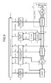
- FIG. 6 is a block diagram illustrating a configuration of a power-generation control unit that constitutes the main component of a control device for use in a hybrid vehicle according to a second embodiment of the present invention.
- the converter 3 functions as a power conversion device and is configured to include a plurality of switching elements and rectifying elements (both not illustrated); is connected between the generator 2 and a DC link portion 13 to which both the battery 5 and the load device 4 are electrically connected; and converts AC power generated by the generator 2 into DC power in accordance with a gate signal Gp_c from the power-generation control unit 7 described later.
- the converter 3 performs a reverse conversion operation to convert DC power supplied from the battery 5 or the load device 4 into AC power.
- the load device 4 connected to the DC link portion 13 is configured to include a drive wheel 4 a , an axle 4 b , an inverter 4 e that functions as a power conversion device in the load device 4 , the electric motor 4 d that drives a vehicle, and a speed reducer 4 c that reduces the speed of the output from the electric motor 4 d and transmits the output, of which the speed is reduced, to the axle 4 b .
- the inverter 4 e is configured to include a plurality of switching elements and rectifying elements (both not illustrated) and converts DC power, which is supplied from at least one of the battery 5 and the converter 3 , to AC power so as to supply the AC power to the electric motor 4 d .
- the inverter 4 e When the electric motor 4 d in the load device 4 performs a regenerative operation, the inverter 4 e is capable of performing a reverse conversion operation to convert AC power regenerated by the electric motor 4 d into DC power.
- the electric motor 4 d in the load device 4 is, for example, a three-phase AC electric motor, and it generates and transmits a drive force to the drive wheel 4 a via the speed reducer 4 c .
- the electric motor 4 d can also operate as a generator. When the speed of a vehicle is reduced, the electric motor 4 d generates regenerated power by being driven by the drive wheel 4 a so as to regenerate power from the vehicle's kinetic energy.
- the battery 5 that is connected to the DC link portion 13 in the same manner as the load device 4 is, for example, a lithium-ion secondary battery. While being charged with the output power by the generator 2 or with regenerated power by the electric motor 4 d , the battery 5 supplies drive power for driving the generator 2 and the electric motor 4 d to the DC link portion 13 .
- the engine control unit 6 controls a throttle opening St of the engine 1 in accordance with an engine-torque command value Te_ref from the upper-level control unit 10 and on the basis of a signal dependent on the engine rotational speed or the like detected by a sensor (not illustrated) with which the engine 1 is provided, the engine control unit 6 controls the engine 1 such that the engine 1 generates a torque that corresponds to the engine-torque command value Te_ref.
- the battery control unit 8 estimates the state of charge (SOC) of the battery 5 on the basis of a battery current value Ibat that is the charge current or discharge current of the battery 5 , which is detected by a current sensor (not illustrated) of the battery 5 , and also on the basis of a battery voltage value Vbat, which is detected by a voltage sensor (not illustrated) of the battery 5 .
- the battery control unit 8 outputs the estimated SOC to the upper-level control unit 10 .
- the battery current value Ibat and the battery voltage value Vbat can be detected by a current sensor and a voltage sensor with which the DC link portion 13 is provided, and the values detected thereby can be input into the battery control unit 8 .
- FIG. 4 is a graph illustrating input and output characteristics of the DC-voltage command-value generator 7 a _ 1 , in which the horizontal axis represents the DC voltage Vdc, and the vertical axis represents the DC-voltage command value Vdc_ref.
- An overvoltage limit voltage Vdc_max and an overvoltage threshold value Vdc_lim are set on the horizontal axis and the vertical axis in FIG. 4 , respectively.
- the overvoltage threshold value Vdc_lim is a voltage value that is set within a range where it does not exceed the overvoltage limit value Vdc_max when the electric motor 4 d in the load device 4 performs a regenerative operation.
- the DC-voltage command-value generator 7 a _ 1 generates the DC-voltage command value Vdc_ref according to the DC voltage Vdc.
- the DC-voltage command value Vdc_ref is determined as follows.
- FIG. 5 is a graph illustrating input and output characteristics of the speed limiter 7 b 1 .
- the speed limiter 7 b _ 1 performs at least one of an upper limit processing and a lower limit processing on the rotational-speed command value ⁇ c_ref 1 (a first rotational-speed command value) that is output from the voltage PI controller 7 a _ 2 so as to output the result as a rotational-speed command value ⁇ c_ref 2 (a second rotational-speed command value).
- the speed limiter 7 b _ 1 transmits information on the rotational-speed command value ⁇ c_ref 2 , on the basis of which the limit processing has been performed, to the upper-level control unit 10 as a generator limit signal ⁇ c_lim.
- the voltage control unit 7 c calculates a voltage command value to be output to the converter 3 on the basis of a control (a so-called vector control) for causing the output torque of the generator 2 to follow the torque command value Tc_ref 1 input from the speed PI controller 7 b _ 2 .
- the voltage control unit 7 c generates a gate signal GP_c for executing a PWM control on the converter 3 on the basis of this calculated voltage command value and outputs the results to the converter 3 .
- the PWM control is executed on the converter 3 by a PWM control device (not illustrated) on the basis of the gate signal GP_c from the voltage control unit 7 c .
- the converter 3 controls the output torque of the generator 2 .
- the torque control technique using the vector control is a publicly-known one and it is referred to, for example, in Non Patent Literature 1 mentioned above.
- the comparator 7 d _ 1 compares the DC voltage Vdc of the DC link portion 13 with the overvoltage threshold value Vdc_lim generated by the rotational-speed command-value generation unit 7 a . When the DC voltage Vdc exceeds the overvoltage threshold value Vdc_lim, the comparator 7 d _ 1 outputs an ON signal as a signal Vdc_sig to the engine-brake determination unit 7 d _ 5 .
- the overvoltage threshold value Vdc_lim is decided within a range where the battery 5 does not reach overvoltage when the electric motor 4 d in the load device 4 performs a regenerative operation as described previously.
- the exhaust-brake determination unit 7 d _ 6 determines whether it is possible to operate an exhaust brake on the basis of two signals that are the engine-brake signal EB from the engine-brake determination unit 7 d _ 5 and the signal ⁇ c_sig 2 from the comparator 7 d _ 3 , and then it outputs a valve operation signal Bs.
- An ON signal as the valve operation signal Bs is output when the engine-brake signal EB is ON and the signal ⁇ c_sig 2 is ON. In a case other than this combination that results in this ON signal, an OFF signal as the valve operation signal Bs is output.
- the upper-level control unit 10 decreases a load-torque command value Ti_ref (see FIG. 1 ) from the load-device control unit 9 so as to reduce regenerated power from the load device 4 in accordance with the generator limit signal ⁇ c_lim from the speed limiter 7 b _ 1 .
- the mechanical brake force is increased to consume excess regenerated power with a mechanical brake.
- the generator limit signal ⁇ c_lim is sent to the motorman's cab (not illustrated) and the like via the upper-level control unit 10 , and the motorman is informed via an indicator lamp or other means.
- the DC-voltage command-value generator 7 a _ 1 in the power-generation control unit 7 sets, in the load device 4 , the overvoltage threshold value Vdc_lim in consideration of the voltage decrease in the battery 5 during the maximum power regeneration.
- the internal resistance of the battery 5 can reliably prevent the DC voltage Vdc from increasing and thus from falling within the overvoltage area.
- This limitation information can be sent from the upper-level control unit 10 via a motorman's cab to the motorman, and therefore the motorman can recognize the fact that the DC-voltage command value Vdc_ref is being generated in a restricted manner.
- the upper-level control unit 10 can reduce regenerated power from the load device 4 . Therefore, the period of time, during which the battery 5 is nearly in a state of overvoltage, is reduced, thereby lessening the degradation of the battery 5 .
- the torque corrector 7 b _ 3 selects the friction-torque command characteristic Teb_chara 1 and outputs the torque correction value Tc_ref 2 on the basis of the friction-torque command characteristic Teb_chara 1 .
- the exhaust-valve operation signal Bs is generated on the basis of the overvoltage threshold value Vdc_lim from the DC-voltage command-value generator 7 a _ 1 . This can effectively simplify the control sequence for using the engine brake or the exhaust brake.
- the voltage control unit 7 c executes a PWM control on an output of the converter 3 on the basis of the torque command value Tc_ref 1 , output through the PI controller 7 b _ 2 by using the speed command value ⁇ c_ref 2 that is input through the speed limiter 7 b _ 1 , and on the basis of the torque correction value Tc_ref 2 , output from the torque corrector 7 b _ 3 . Therefore, the torque correction value Tc_ref 2 from the torque corrector 7 b _ 3 acts as a feed-forward function to a response delay of the voltage PI controller 7 a _ 2 , which is caused when the DC voltage Vdc is changed. Accordingly, regenerated power from the load device 4 can be quickly and effectively consumed.
Abstract
A power-generation control unit controls the amount of power a generator can generate, when it is connected to an engine, by controlling a converter that converts AC power output by the generator to DC power. The power-generation control unit calculates a rotational-speed command value ωc_ref1 for the generator on the basis of a differential voltage value ΔVdc between a DC-voltage command value Vdc_ref for a power storage device and a DC voltage Vdc of a DC link portion; and executes a PWM control on an output of the converter on the basis of this rotational-speed command value ωc_ref1 such that the rotational speed ωc of the generator follows the rotational-speed command value ωc_ref1 and also such that the DC voltage Vdc follows the DC-voltage command value Vdc_ref so as to prevent overvoltage.
Description
The present invention relates to a control device for use in a hybrid vehicle.
A hybrid vehicle is a railway vehicle that is configured to use a generator to convert an engine output into electric power and to drive an electric motor using the electric power from the generator and electric power from a power storage device such as a battery so as to control the propulsion of the vehicle.
In the hybrid vehicle configured as described above, which has been disclosed, for example, in Patent Literature 1, a DC-voltage command value for a DC bus is set on the basis of the target output of the battery and the charging rate of the battery, with the output from the battery to the DC bus controlled so as to reach the target output; and when the output from the battery to the DC bus reaches the target output, the output from the generator is controlled such that the DC-voltage level of a converter approaches the DC-voltage command value. The contents of Non Patent Literature 1 mentioned below are described later.
- Patent Literature 1: Japanese Patent Application Laid-open No. 2011-168226
- Non Patent Literature 1: “Actual Theory and Design of AC Servo System, From Basic to Software Servo”, by Hidehiko Sugimoto, Masato Koyama, Shinzo Tamai, p 99-103
With the above conventional technique, however, when the railway vehicle runs on a long downward slope for example, regenerated power from a load device is continuously charged to the battery that is a power storage device, and therefore there has been a problem in that the battery may be overcharged and may reach overvoltage.
The present invention has been made to solve the above problems, and an objective of the present invention is to provide a control device for use in a hybrid vehicle that can prevent a power storage device thereof from being overcharged and from reaching overvoltage.
To solve the problems and achieve the objective, the present invention relates to a control device for use in a hybrid vehicle that includes: a generator that is driven by an engine; a converter that converts AC power output by the generator to DC power; a power-generation control unit that controls, by controlling the converter, an amount of power generated by the generator; a power storage device that is electrically connected to the converter; and an upper-level control unit that controls at least an operation of the power-generation control unit. The power-generation control unit includes an overvoltage prevention unit that calculates a rotational-speed command value for the generator on the basis of information on a differential voltage value between a DC-voltage command value for an electrical connection end of the power storage device and a DC voltage of the electrical connection end, and that executes a PWM control on an output of the converter on the basis of the rotational-speed command value, such that a rotational speed of the generator follows the rotational-speed command value and also such that the DC voltage follows the DC-voltage command value.
The present invention can provide a control device for use in a hybrid vehicle that can prevent a power storage device from being overcharged and from reaching overvoltage.
Exemplary embodiments of a control device for use in a hybrid vehicle according to the present invention will be described below in detail with reference to the accompanying drawings. The present invention is not limited to the embodiments.
The engine 1 is, for example, a diesel engine and it transmits a drive force to the generator 2 in order to generate power. The engine 1 can be configured to operate an engine brake at the time of a regenerative operation on an electric motor 4 d, which is one of the constituent elements of the load device 4. It can also be configured to operate what is called an exhaust brake (an assisted engine brake) that reduces the rotational speed of the engine 1 by closing a valve provided at a location within an exhaust pipe so as to increase the exhaust pressure, which thereby increases the pumping loss of the engine 1. Further, the engine 1 can be configured to switch between the engine brake and the exhaust brake by executing an ON/OFF control on the exhaust valve.
The generator 2 is, for example, a three-phase AC generator and it functions as a power supply source that generates electric power by rotating a rotor driven by the drive force of the engine 1 and that supplies the generated electric power (AC power) to at least one of the load device 4 and the battery 5. The generator 2 can also operate as an electric motor and can consume electric power when cranking the engine 1 to start the engine 1, or by rotating the engine 1 by using the drive force of the generator 2.
The converter 3 functions as a power conversion device and is configured to include a plurality of switching elements and rectifying elements (both not illustrated); is connected between the generator 2 and a DC link portion 13 to which both the battery 5 and the load device 4 are electrically connected; and converts AC power generated by the generator 2 into DC power in accordance with a gate signal Gp_c from the power-generation control unit 7 described later. When the generator 2 is operated as an electric motor, the converter 3 performs a reverse conversion operation to convert DC power supplied from the battery 5 or the load device 4 into AC power.
As illustrated in FIG. 1 , the load device 4 connected to the DC link portion 13 is configured to include a drive wheel 4 a, an axle 4 b, an inverter 4 e that functions as a power conversion device in the load device 4, the electric motor 4 d that drives a vehicle, and a speed reducer 4 c that reduces the speed of the output from the electric motor 4 d and transmits the output, of which the speed is reduced, to the axle 4 b. The inverter 4 e is configured to include a plurality of switching elements and rectifying elements (both not illustrated) and converts DC power, which is supplied from at least one of the battery 5 and the converter 3, to AC power so as to supply the AC power to the electric motor 4 d. When the electric motor 4 d in the load device 4 performs a regenerative operation, the inverter 4 e is capable of performing a reverse conversion operation to convert AC power regenerated by the electric motor 4 d into DC power. The electric motor 4 d in the load device 4 is, for example, a three-phase AC electric motor, and it generates and transmits a drive force to the drive wheel 4 a via the speed reducer 4 c. The electric motor 4 d can also operate as a generator. When the speed of a vehicle is reduced, the electric motor 4 d generates regenerated power by being driven by the drive wheel 4 a so as to regenerate power from the vehicle's kinetic energy.
The battery 5 that is connected to the DC link portion 13 in the same manner as the load device 4 is, for example, a lithium-ion secondary battery. While being charged with the output power by the generator 2 or with regenerated power by the electric motor 4 d, the battery 5 supplies drive power for driving the generator 2 and the electric motor 4 d to the DC link portion 13.
The engine control unit 6 controls a throttle opening St of the engine 1 in accordance with an engine-torque command value Te_ref from the upper-level control unit 10 and on the basis of a signal dependent on the engine rotational speed or the like detected by a sensor (not illustrated) with which the engine 1 is provided, the engine control unit 6 controls the engine 1 such that the engine 1 generates a torque that corresponds to the engine-torque command value Te_ref.
The power-generation control unit 7 controls the voltage supplied to the generator 2 by controlling the switching of the switching elements that constitute the converter 3 according to a rotational speed ωc of the generator 2, which is detected by the speed sensor 12 mounted on the generator 2, and according to the condition of a DC voltage value Vdc, which is detected by the voltage sensor 11 with which the DC link portion 13 is provided. The power-generation control unit 7 transmits the controlling conditions to the upper-level control unit 10.
The battery control unit 8 estimates the state of charge (SOC) of the battery 5 on the basis of a battery current value Ibat that is the charge current or discharge current of the battery 5, which is detected by a current sensor (not illustrated) of the battery 5, and also on the basis of a battery voltage value Vbat, which is detected by a voltage sensor (not illustrated) of the battery 5. The battery control unit 8 outputs the estimated SOC to the upper-level control unit 10. The battery current value Ibat and the battery voltage value Vbat can be detected by a current sensor and a voltage sensor with which the DC link portion 13 is provided, and the values detected thereby can be input into the battery control unit 8.
The load-device control unit 9 generates a gate signal GP_i, which is what is called a PWM switching signal, for controlling the inverter 4 e such that the torque of the electric motor 4 d follows an electric-motor torque command value Ti_ref from the upper-level control unit 10. The load-device control unit 9 outputs this generated gate signal GP_i to the load device 4 in order to control the inverter 4 e.
The function of the upper-level control unit 10 is to manage and monitor all of the operations of each of the constituent elements previously described. More specifically, the upper-level control unit 10 controls the generator 2 via the power-generation control unit 7 and the converter 3 on the basis of the rotating speed ωc of the generator 2, information on the DC voltage Vdc obtained by the voltage sensor 11 of the DC link portion 13, and a control command Do_2 generated on the basis of the driving command Do_1 that is input thereto. Also, the upper-level control unit 10 controls the engine 1 via the engine control unit 6. Further, the upper-level control unit 10 controls the engine 1 via the engine control unit 6 on the basis of an engine brake signal EB from the power-generation control unit 7, monitors the limitation signal from the power-generation control unit 7, and notifies the motorman's cab (not illustrated) of necessary information.
In the device configuration described above, in order to solve the problem in which, when an engine brake is used during power regeneration in the load device 4, the engine 1 rotates at a higher speed due to regenerated power from the load device 4 and also the battery 5 reaches its overvoltage, the following generator control is executed to prevent the battery 5 from being overcharged and from reaching its overvoltage while at the same time preventing the engine 1 from over-speeding.
A more detailed operation of the DC-voltage command-value generator 7 a_1 is described below with reference to FIG. 4 . FIG. 4 is a graph illustrating input and output characteristics of the DC-voltage command-value generator 7 a_1, in which the horizontal axis represents the DC voltage Vdc, and the vertical axis represents the DC-voltage command value Vdc_ref. An overvoltage limit voltage Vdc_max and an overvoltage threshold value Vdc_lim are set on the horizontal axis and the vertical axis in FIG. 4 , respectively. The overvoltage limit voltage Vdc_max is the voltage value of the battery 5 when the state of charge (SOC) of the battery 5 is full (SOC=100%), for example. The overvoltage threshold value Vdc_lim is a voltage value that is set within a range where it does not exceed the overvoltage limit value Vdc_max when the electric motor 4 d in the load device 4 performs a regenerative operation. The DC-voltage command-value generator 7 a_1 generates the DC-voltage command value Vdc_ref according to the DC voltage Vdc. However, when the DC voltage Vdc becomes equal to or higher than the overvoltage threshold value Vdc_lim, excess regenerated power due to the engine brake is consumed. Therefore, in a case in which the electric motor 4 d in the load device 4 performs a regenerative operation, the DC-voltage command value Vdc_ref is determined as follows.
Interval (1) (the voltage on the horizontal axis is between 0 and the overvoltage threshold value Vdc_lim)
In this interval, the DC-voltage command-value generator 7 a_1 outputs the DC-voltage command value Vdc_ref that corresponds with the DC voltage Vdc.
Interval (2) (the voltage on the horizontal axis is equal to or higher than the overvoltage threshold value Vdc_lim)
In this interval, the DC-voltage command-value generator 7 a_1 outputs the DC-voltage command value Vdc_ref that is equal to the overvoltage threshold value Vdc_lim regardless of the DC voltage Vdc.
As described above, when the value of the DC voltage Vdc falls within the interval (2), the DC-voltage command-value generator 7 a_1 determines that the battery 5 is in a slight overvoltage state; therefore, it starts an engine brake control and then generates and outputs a command value for consuming regenerated power from the load device 4 for a rotational friction force of the engine 1.
Further, the DC-voltage command-value generator 7 a_1 transmits information on the overvoltage threshold value Vdc_lim to the exhaust-valve operation control unit, 7 d described later, and to the upper-level control unit 10. The overvoltage threshold value Vdc_lim can be calculated and set within a range in which it does not exceed the overvoltage limit voltage Vdc_max and for each train line in advance on the basis of the maximum regenerated power of inverter power flowing from the inverter 4 e to the DC link portion 13. The overvoltage threshold value Vdc_lim transmitted to the upper-level control unit 10 is stored in the upper-level control unit 10 for each elapsed time.
This section refers back to FIG. 3 . A differential voltage value ΔVdc between the DC voltage Vdc and the DC-voltage command value Vdc_ref, generated by the DC-voltage command-value generator 7 a 1, is input to the voltage PI controller 7 a_2. The voltage PI controller 7 a_2 uses a gain that is set in advance on the basis of a desired voltage control response and performs a proportional-integral calculation, for example, on the differential voltage value ΔVdc so as to calculate and output the rotational-speed command value ωc_ref1. The calculated rotational-speed command value ωc_ref1 is input to the speed control unit 7 b arranged at the subsequent stage.
Next, the speed control unit 7 b will be described. As illustrated in FIG. 3 , the speed control unit 7 b is configured to include a speed limiter 7 b_1, a speed PI controller 7 b_2, and the like. The speed limiter 7 b_1 limits the rotational-speed command value ωc_ref1 from the rotational-speed command-value generation unit 7 a. Being on the basis of a differential rotating speed between this limited output value and a generator rotating speed (which is synonymous with a generator rotational speed) ωc, the speed PI controller 7 b_2 generates a torque command value Tc_ref1 for the generator 2.
A more detailed operation of the speed limiter 7 b 1 is described below with reference to FIG. 5 . FIG. 5 is a graph illustrating input and output characteristics of the speed limiter 7 b 1. The speed limiter 7 b_1 performs at least one of an upper limit processing and a lower limit processing on the rotational-speed command value ωc_ref1 (a first rotational-speed command value) that is output from the voltage PI controller 7 a_2 so as to output the result as a rotational-speed command value ωc_ref2 (a second rotational-speed command value).
For example, a limit value (a lower-limit value) used for the lower limit processing is defined as an idling rotating speed ωe_idol (=X0) of the engine 1 and is to prevent the rotational-speed command value ωc_ref2 from becoming equal to or lower than the idling rotating speed ωe_idol. A limit value (an upper-limit value) used for the upper limit processing is defined as an engine rotating speed ωe_lim (=Y0) that is set by taking into consideration the estimated margin to a maximum rotating speed ωe_max when an engine brake and an exhaust brake of the engine 1 are operated so as to prevent the rotational-speed command value ωc_ref2 from becoming equal to or higher than the engine rotating speed ωe_lim. In addition, the speed limiter 7 b_1 transmits information on the rotational-speed command value ωc_ref2, on the basis of which the limit processing has been performed, to the upper-level control unit 10 as a generator limit signal ωc_lim.
Referring back to FIG. 3 , a differential rotational-speed value Δωc, which is a value between the rotational-speed command value ωc_ref2 output from the speed limiter 7 b_1 and the generator rotational speed ωc obtained from a rotor shaft of the generator 2, is input to the speed PI controller 7 b 2. The speed PI controller 7 b_2 uses a gain that is set in advance on the basis of a desired speed control response to perform a proportional-integral calculation, for example, on the differential rotational-speed value Δωc so as to calculate and output the torque command value Tc_ref1. The calculated torque command value Tc_ref1 is input to the voltage control unit 7 c arranged at the subsequent stage.
Next, the voltage control unit 7 c will be described. In FIG. 3 , the voltage control unit 7 c calculates a voltage command value to be output to the converter 3 on the basis of a control (a so-called vector control) for causing the output torque of the generator 2 to follow the torque command value Tc_ref1 input from the speed PI controller 7 b_2. The voltage control unit 7 c generates a gate signal GP_c for executing a PWM control on the converter 3 on the basis of this calculated voltage command value and outputs the results to the converter 3. The PWM control is executed on the converter 3 by a PWM control device (not illustrated) on the basis of the gate signal GP_c from the voltage control unit 7 c. The converter 3 controls the output torque of the generator 2. The torque control technique using the vector control is a publicly-known one and it is referred to, for example, in Non Patent Literature 1 mentioned above.
Next, the exhaust-valve operation control unit 7 d will be described. As illustrated in FIG. 3 , the exhaust-valve operation control unit 7 d is configured to include comparators 7 d_1 to 7 d_3, an acceleration/coasting/regeneration determination unit 7 d_4, an engine-brake determination unit 7 d_5, an exhaust-brake determination unit 7 d_6, and other devices.
The comparator 7 d_1 compares the DC voltage Vdc of the DC link portion 13 with the overvoltage threshold value Vdc_lim generated by the rotational-speed command-value generation unit 7 a. When the DC voltage Vdc exceeds the overvoltage threshold value Vdc_lim, the comparator 7 d_1 outputs an ON signal as a signal Vdc_sig to the engine-brake determination unit 7 d_5. Note that the overvoltage threshold value Vdc_lim is decided within a range where the battery 5 does not reach overvoltage when the electric motor 4 d in the load device 4 performs a regenerative operation as described previously.
The comparator 7 d_2 compares the generator rotating speed ωc with the idling rotating speed ωc_idol of the engine 1. When the generator rotating speed ωc exceeds the idling rotating speed ωe_idol, the comparator 7 d_2 outputs an ON signal of a signal ωc_sig1 to the engine-brake determination unit 7 d_5.
The comparator 7 d_3 compares the generator rotating speed ωc with an engine rotating speed ωe_haiki when the exhaust brake of the engine 1 operates. When the generator rotating speed ωc exceeds the engine rotating speed ωe_haiki, the comparator 7 d_3 outputs an ON signal of a signal ωc_sig2 to the exhaust-brake determination unit 7 d_6. The engine rotating speed ωe_haiki during the operation of an exhaust brake is a rotating speed with a value between the idling rotating speed ωe_idol and the allowable maximum rotating speed ωe_lim of the engine 1, as illustrated in FIG. 8 and which is described later. For example, when the idling rotating speed ωe_idol is around 600 rpm and the allowable maximum rotating speed ωe_lim is 2000 rpm, then the engine rotating speed ωe_haiki is around 1200 rpm when an exhaust brake operates.
The acceleration/coasting/regeneration determination unit 7 d_4 receives a driving operation signal Do_2 from the upper-level control unit 10, and it outputs this information to the engine-brake determination unit 7 d_5 as a mode (acceleration/coasting/regeneration) signal.
The engine-brake determination unit 7 d_5 determines whether it is possible to operate an engine brake on the basis of three signals: the signal Vdc_sig from the comparator 7 d_1; the mode signal from the acceleration/coasting/regeneration determination unit 7 d_4; and the signal ωc_sig1 from the comparator 7 d_2. The engine-brake determination unit 7 d_5 then outputs the engine-brake signal EB to the exhaust-brake determination unit 7 d_6 and to the upper-level control unit 10. When the signal Vdc_sig is ON, the mode signal indicates regeneration, and when the signal ωc_sig1 is ON, an ON signal as an engine-brake signal EB is output to the exhaust-brake determination unit 7 d_6 and to the upper-level control unit 10. In a case other than this combination described above that results in the ON signal, an OFF signal as an engine-brake signal EB is output to the exhaust-brake determination unit 7 d_6 and to the upper-level control unit 10.
The exhaust-brake determination unit 7 d_6 determines whether it is possible to operate an exhaust brake on the basis of two signals that are the engine-brake signal EB from the engine-brake determination unit 7 d_5 and the signal ωc_sig2 from the comparator 7 d_3, and then it outputs a valve operation signal Bs. An ON signal as the valve operation signal Bs is output when the engine-brake signal EB is ON and the signal ωc_sig2 is ON. In a case other than this combination that results in this ON signal, an OFF signal as the valve operation signal Bs is output.
The control sequence of the power-generation control unit 7 is as described above. Due to this control sequence, the upper-level control unit 10 performs the following operation when an engine brake is operated so as to prevent the battery 5 from reaching overvoltage.
(Control to be Executed on Engine Control Unit 6)
When the DC voltage Vdc becomes equal to or higher than the overvoltage threshold value Vdc_lim during the regenerative operation in the electric motor 4 d, and when the generator rotating speed ωc becomes equal to or higher than the idling rotating speed, then an ON signal as an engine brake signal EB is output to the upper-level control unit 10. At this time, the upper-level control unit 10 outputs an engine torque command Te_ref (see FIG. 1 ) that is equal to “0 (zero)” to the engine control unit 6. The engine control unit 6, to which the engine torque command Te_ref that is equal to 0 has been output, transmits to the engine 1 a command to close the throttle opening St (see FIG. 1 ) of the engine 1 so as to stop the fuel supply to the engine 1. Thereafter, the regenerated power from the load device 4 is not used to charge the battery 5, but is consumed by the friction load of the engine 1, thus preventing the battery 5 from reaching overvoltage.
(Control to be Executed on Load-Device Control Unit 9)
While executing the control described above, the upper-level control unit 10 decreases a load-torque command value Ti_ref (see FIG. 1 ) from the load-device control unit 9 so as to reduce regenerated power from the load device 4 in accordance with the generator limit signal ωc_lim from the speed limiter 7 b_1. According to the amount by which the load-torque command value Ti_ref is decreased, the mechanical brake force is increased to consume excess regenerated power with a mechanical brake. The generator limit signal ωc_lim is sent to the motorman's cab (not illustrated) and the like via the upper-level control unit 10, and the motorman is informed via an indicator lamp or other means.
As described above, in the control device for use in a hybrid vehicle according to the first embodiment, when the DC voltage Vdc becomes equal to or higher than the overvoltage threshold value Vdc_lim, the power-generation control unit 7 executes a control in which the differential voltage ΔVdc between the DC voltage Vdc and the DC-voltage command value Vdc_ref is first output as the rotational-speed command value ωc_ref1, and further the upper/lower limit processing is performed on the rotational-speed command value ωc_ref1 in the speed limiter 7 b_1 so as to output a generator rotating speed ωc_ref2. By executing this control, excessive regenerated power can be consumed by an engine brake or an exhaust brake, and overcharge and overvoltage can be prevented, while reducing engine over-speed.
Note that it is preferable that the DC-voltage command-value generator 7 a_1 in the power-generation control unit 7 sets, in the load device 4, the overvoltage threshold value Vdc_lim in consideration of the voltage decrease in the battery 5 during the maximum power regeneration. By taking into account this point, the internal resistance of the battery 5 can reliably prevent the DC voltage Vdc from increasing and thus from falling within the overvoltage area.
A closed-loop speed control system, on which the upper/lower limit processing has been performed by the speed limiter 7 b_1, is provided on the input side of a voltage control system. This can reliably prevent the engine 1 from rotating at an abnormal speed. Specifically, even when the DC voltage Vdc is significantly changed by a voltage decrease caused by the internal resistance of the battery 5, the speed limiter 7 b_1 in the speed control system can prevent the mechanical system constituted by the generator 2 and the engine 1 from rotating at an abnormal speed. It is more preferable to take into account the maximum value of a current that can be absorbed by the battery 5 (maximum absorbed current) in addition to the internal resistance of the battery 5.
It is preferable to set the lower-limit value X0 of the generator rotational speed in the speed limiter 7 b_1 to the idling speed ωe_idol of the engine 1 or higher. With the setting as described above, the rotational-speed command value ωc_ref2 in the power-generation control unit 7 is controlled so as not to fall below the idling speed ωe_idol. Therefore, the engine 1 can be prevented from rotating in the reverse direction and accordingly can continue a stable operation.
It is preferable that the speed limiter 7 b_1 provides the upper-limit value Y0 of the generator rotational speed with a margin to the allowable maximum rotating speed ωe_max while an engine brake and an exhaust brake of the engine 1 are being operated, so the upper-limit value Y0 is preferably set to a value slightly smaller than the allowable maximum rotating speed ωe_max. Due to such a setting as that described above being set, the engine 1 can be reliably prevented from rotating at a high speed, and thus from being mechanically damaged.
It is preferable to transmit the generator limit signal ωc_lim in the speed limiter 7 b_1 to the upper-level control unit 10. This limitation information can be sent from the upper-level control unit 10 via a motorman's cab to the motorman, and therefore the motorman can recognize the fact that the DC-voltage command value Vdc_ref is being generated in a restricted manner.
By transmitting the generator limit signal ωc_lim to the upper-level control unit 10, the upper-level control unit 10 can reduce regenerated power from the load device 4. Therefore, the period of time, during which the battery 5 is nearly in a state of overvoltage, is reduced, thereby lessening the degradation of the battery 5.
Next, a control device for use in a hybrid vehicle according to a second embodiment of the present invention will be described. FIG. 6 is a block diagram illustrating a configuration of the power-generation control unit 7 that constitutes the main component of the control device for use in a hybrid vehicle according to the second embodiment of the present invention. The second embodiment differs when compared with the power-generation control unit 7 in the first embodiment in that the valve operation signal Bs is transmitted from the exhaust-valve operation control unit 7 d to the speed control unit 7 b and in what the speed control unit 7 b internally processes.
Here, a more detailed operation of the newly-provided torque corrector 7 b_3 with reference to FIG. 8 is given. FIG. 8 is a graph illustrating input and output characteristics of the torque corrector 7 b_3, in which the horizontal axis represents the rotational speed ωc of the generator 2 and the vertical axis represents the torque correction value Tc_ref2 that is output from the torque corrector 7 b_3.
As illustrated in FIG. 8 , in the map to which the torque corrector 7 b_3 refers, each of a friction-torque command characteristic Teb_chara1 during operation of an engine brake for the engine 1 and a friction-torque command characteristic Teb_chara2 during the operation of an exhaust brake for the engine 1 is defined as a function of the generator rotating speed ωc.
When the exhaust-valve operation signal Bs, which is calculated by the exhaust-brake determination unit 7 d_6 in the exhaust-valve operation control unit 7 d in the power-generation control unit 7, is OFF, then the torque corrector 7 b_3 selects the friction-torque command characteristic Teb_chara1 and outputs the torque correction value Tc_ref2 on the basis of the friction-torque command characteristic Teb_chara1. Further, when the generator rotating speed ωc increases and an ON signal as an exhaust-valve operation signal Bs is output, then the torque corrector 7 b_3 selects the friction-torque command characteristic Teb_chara2 and outputs the torque correction value Tc_ref2 on the basis of the selected friction-torque command characteristic Teb_chara2. The switching between an engine brake and an exhaust brake is performed in accordance with an ON/OFF signal output as the exhaust-valve operation signal Bs.
Next, a method of setting a parameter value that is defined in the map of the torque corrector 7 b_3 will be described in detail with reference to FIG. 8 .
First, with the method of setting a lower-limit value, a lower-limit value X0 of the generator rotational speed ωc illustrated by a dot-and-dash line is set such that the generator rotating speed ωc corresponds to the idling rotating speed ωe_idol of the engine 1; and the torque correction value Tc_ref2 is set lower for the engine brake than that for the exhaust brake.
Furthermore, an upper-limit value is provided with a margin to the allowable maximum rotating speed ωe_lim that is a limit value in a design process when the engine brake and the exhaust brake are applied in the engine 1. Therefore, the upper-limit value is set to a value (Y0) slightly smaller than this allowable maximum rotating speed ωe_lim. This upper-limit set value Y0 for the engine brake and the exhaust brake is set lower than the allowable maximum rotating speed ωe_lim so as to become, for example, 0.9 times as high as the allowable maximum rotating speed.
Note that, due to protection of the engine 1, it is preferable to set the upper-limit value such that a generator torque Tc_ref2 becomes equal to 0 in an area where the generator rotating speed ωc is equal to or higher than the allowable maximum rotating speed ωe_lim.
As described above, in the control device for use in a hybrid vehicle according to the second embodiment, the exhaust-valve operation signal Bs is generated on the basis of the overvoltage threshold value Vdc_lim from the DC-voltage command-value generator 7 a_1. This can effectively simplify the control sequence for using the engine brake or the exhaust brake.
The voltage control unit 7 c executes a PWM control on an output of the converter 3 on the basis of the torque command value Tc_ref1, output through the PI controller 7 b_2 by using the speed command value ωc_ref2 that is input through the speed limiter 7 b_1, and on the basis of the torque correction value Tc_ref2, output from the torque corrector 7 b_3. Therefore, the torque correction value Tc_ref2 from the torque corrector 7 b_3 acts as a feed-forward function to a response delay of the voltage PI controller 7 a_2, which is caused when the DC voltage Vdc is changed. Accordingly, regenerated power from the load device 4 can be quickly and effectively consumed.
In the torque corrector 7 b_3 there is a plurality of torque command characteristics each based on the presence or absence of the exhaust-valve operation command Bs, and it is preferable that the friction-torque command characteristic Teb_chara1 at the time of operating an engine brake and the friction-torque command characteristic Teb_chara2 at the time of operating an exhaust brake are separately defined for each function for the generator rotating speed ωc. The torque corrector 7 b_3 has these two friction-torque command characteristics; therefore, when the exhaust-valve operation command Bs is output to the torque corrector 7 b_3 in the speed control unit 7 b, the friction-torque command characteristic Teb_chara2 is selected from the friction-torque command characteristic Teb_chara1, and the torque correction value Tc_ref2 is output on the basis of the selected friction-torque command characteristic Teb_chara2. Accordingly, the torque correction value Tc_ref2 acts as a feed-forward function more significantly than when the engine brake alone is used, and thus the regenerated power from the load device 4 can be effectively consumed with a quicker response.
In the speed area of the engine 1, which is equal to or higher than the allowable maxim rotating speed ωe_lim, it is preferable that the torque correction value Tc_ref2, output from the torque corrector 7 b_3, is set to be zero. With the setting described above, even when the rotating speed ωc of the generator 2 is increased rapidly, the torque correction value Tc_ref2 from the torque corrector 7 b_3 is still equal to zero, so the control operation by the power-generation control unit 7 becomes effectively stable.
Next, a control device for use in a hybrid vehicle according to a third embodiment of the present invention will be described. FIG. 9 is a block diagram illustrating the overall configuration of a hybrid vehicle system including a control device for use in a hybrid vehicle according to the third embodiment of the present invention. The system control unit in the third embodiment differs when compared with that in the first embodiment in that a breaker 14 is provided between the battery 5, the converter 3, and the inverter 4 e of the load device 4; and that a battery-open control signal line is connected from the upper-level control unit 10 to the battery 5.
The power-generation control unit 7 used in the third embodiment can be the power-generation control unit 7 used in either the first embodiment or in the second embodiment. The power-generation control unit 7 in both the first embodiment and the second embodiment is configured to output the generator limit signal ωc_lim from the speed limiter 7 b_1 to the upper-level control unit 10. The upper-level control unit 10 monitors the generator limit signal ωc_lim. When the generator limit signal ωc_lim becomes equal to or greater than an allowable value, the upper-level control unit 10 outputs a battery-open signal BATOPEN to the breaker 14 so as to control the battery 5 such that it is open. Due to this control, a regenerated current does not flow into the battery 5, and regenerated power from the load device 4 can be blocked. Therefore, overvoltage to the battery 5 and an excessive temperature increase in the battery 5 are effectively prevented.
The configurations described in the first to third embodiments are only examples of the configuration of the present invention. These configurations can be combined with other well-known techniques, and it is not necessary to say that the present invention can be configured while modifying the configurations without departing from the scope of the invention, such as omitting a part of these configurations.
As described above, the present invention is useful as a control device for use in a hybrid vehicle that can prevent a power storage device from being overcharged and from reaching overvoltage.
1 engine, 2 generator, 3 converter, 4 load device, 4 a drive wheel, 4 b axle, 4 c speed reducer, 4 d electric motor, 4 e inverter, 5 battery, 6 engine control unit, 7 power-generation control unit, 7 a rotational-speed command-value generation unit, 7 a_1 DC-voltage command-value generator, 7 a_2 voltage PI controller, 7 b speed control unit, 7 b_1 speed limiter, 7 b_2 speed PI controller, 7 b_3 torque corrector, 7 c voltage control unit, 7 d exhaust-valve operation control unit, 7 d_1 comparator, 7 d_2 comparator, 7 d_3 comparator, 7 d_4 acceleration/coasting/regeneration determination unit, 7 d_5 engine-brake determination unit, 7 d_6 exhaust-brake determination unit, 8 battery control unit, 9 load-device control unit, 10 upper-level control unit, 11 voltage sensor, 12 speed sensor, 13 DC link portion, 14 breaker.
Claims (15)
1. A control device for use in a hybrid vehicle that is applied to a hybrid vehicle that includes
a generator that is driven by an engine,
a converter that converts AC power output by the generator to DC power,
a power storage device that is electrically connected to the converter, and
a load device that is driven by using at least one of electric power output by the converter and electric power from the power storage device and that performs a regenerative operation,
the control device for use in a hybrid vehicle comprising:
a power-generation control unit that controls, by controlling the converter, an amount of power generated by the generator;
an upper-level control unit that controls at least an operation of the power-generation control unit, wherein
the power-generation control unit includes an overvoltage prevention unit that
calculates a rotational-speed command value for the generator by using information on a differential voltage value between a DC-voltage command value that is set within a range, where it does not exceed an overvoltage threshold value that is equal to or lower than a fully-charged voltage value, for an electrical connection end of the power storage device and a DC voltage of the electrical connection end, and that
executes a PWM control on an output of the converter, by setting the differential voltage value as the rotational-speed command value when the DC voltage becomes equal to or higher than the overvoltage threshold value, such that a rotational speed of the generator follows the rotational-speed command value and therefore the DC voltage follows the DC-voltage command value, and
when the DC voltage becomes equal to or higher than the overvoltage threshold value during a regenerative operation in the load device and when a rotational speed of the generator becomes equal to or higher than an idling rotating speed, the upper-level control unit outputs an engine torque command that is equal to zero in order to prompt the engine to operate an engine brake.
2. The control device for use in a hybrid vehicle according to claim 1 , wherein
the overvoltage prevention unit includes
a rotational-speed command-value calculation unit that calculates the rotational-speed command value by using the DC-voltage command value and the DC voltage,
a speed control unit that generates a torque command value for the generator on the basis of a differential value between the rotational-speed command value and a rotational speed of the generator, and
a voltage control unit that executes a PWM control on the converter on the basis of the torque command value.
3. The control device for use in a hybrid vehicle according to claim 2 , wherein
the rotational-speed command-value calculation unit includes
a DC-voltage command generator that generates the DC-voltage command value, and
a voltage PI controller that calculates the rotational-speed command value on the basis of the differential voltage value.
4. The control device for use in a hybrid vehicle according to claim 3 , wherein
an overvoltage threshold value, at which the DC-voltage command value starts being limited, is set in the DC-voltage command generator.
5. The control device for use in a hybrid vehicle according to claim 4 , wherein
the overvoltage threshold value is set in consideration of a voltage fluctuation range that is estimated in advance on the basis of an internal resistance of the power storage device and a maximum absorbed current of the power storage device.
6. The control device for use in a hybrid vehicle according to claim 2 , wherein
the speed control unit includes
a speed limiter that limits at least one of a lower-limit value and an upper-limit value of the rotational-speed command value, and
a speed PI controller that calculates the torque command value on the basis of a rotational-speed command value that is input via the speed limiter.
7. The control device for use in a hybrid vehicle according to claim 6 , wherein
the lower-limit value of the rotational-speed command value in the speed limiter is set equal to or higher than an idling rotating speed of the engine.
8. The control device for use in a hybrid vehicle according to claim 6 , wherein
the upper-limit value of the rotational-speed command value in the speed limiter is set equal to or lower than an allowable rotating speed when an engine brake operates.
9. The control device for use in a hybrid vehicle according to claim 6 , wherein
limit processing information in the speed limiter is transmitted to the upper-level control unit.
10. The control device for use in a hybrid vehicle according to claim 9 , wherein
the upper-level control unit adjusts regenerated power to be generated by a load device on the basis of the limit processing information.
11. The control device for use in a hybrid vehicle according to claim 9 , wherein
the upper-level control unit outputs a signal that makes an electrical connection end open between the power storage device and the converter on the basis of the limit processing information in the speed limiter.
12. The control device for use in a hybrid vehicle according to claim 6 , wherein
the power-generation control unit further includes an exhaust-valve operation control unit that outputs an exhaust-valve operation command for the engine on the basis of the DC voltage, a rotational speed of the generator, and the overvoltage threshold value.
13. The control device for use in a hybrid vehicle according to claim 6 , further comprising
a torque corrector that
includes a torque command characteristic of the engine, and
outputs a torque correction value on the basis of a rotational speed of the generator, wherein
the voltage control unit executes a PWM control on an output of the converter on the basis of the rotational-speed command value that is input via the speed limiter and on the basis of the torque correction value that is output from the torque corrector.
14. The control device for use in a hybrid vehicle according to claim 12 , further comprising
a torque corrector that
includes a plurality of torque command characteristics, each according to the presence or absence of the exhaust-valve operation command,
selects one of the torque command characteristics on the basis of an exhaust valve operation in the engine, and
outputs a torque correction value on the basis of this selected torque command characteristic, wherein
the voltage control unit executes a PWM control on an output of the converter on the basis of the rotational-speed command value that is input via the speed limiter and on the basis of the torque correction value that is output from the torque corrector.
15. The control device for use in a hybrid vehicle according to claim 13 , wherein
a torque correction value to be output from the torque corrector is set to zero in a speed area that is equal to or higher than an allowable maximum rotating speed of the engine.
Applications Claiming Priority (1)
| Application Number | Priority Date | Filing Date | Title |
|---|---|---|---|
| PCT/JP2012/068519 WO2014013622A1 (en) | 2012-07-20 | 2012-07-20 | Hybrid vehicle control device |
Publications (2)
| Publication Number | Publication Date |
|---|---|
| US20150174998A1 US20150174998A1 (en) | 2015-06-25 |
| US9469185B2 true US9469185B2 (en) | 2016-10-18 |
Family
ID=49948473
Family Applications (1)
| Application Number | Title | Priority Date | Filing Date |
|---|---|---|---|
| US14/415,915 Active 2032-09-30 US9469185B2 (en) | 2012-07-20 | 2012-07-20 | Control device for hybrid vehicle |
Country Status (5)
| Country | Link |
|---|---|
| US (1) | US9469185B2 (en) |
| EP (1) | EP2875978B1 (en) |
| JP (1) | JP5384771B1 (en) |
| AU (1) | AU2012385593B2 (en) |
| WO (1) | WO2014013622A1 (en) |
Cited By (4)
| Publication number | Priority date | Publication date | Assignee | Title |
|---|---|---|---|---|
| US20160356210A1 (en) * | 2014-02-25 | 2016-12-08 | Mitsubishi Heavy Industries, Ltd. | Turbocharger and marine vessel |
| US20180297466A1 (en) * | 2017-04-17 | 2018-10-18 | Autonomous Tractor Corporation | Electric and hydraulic drive system and methods |
| EP3569439A1 (en) * | 2018-05-15 | 2019-11-20 | Toyota Jidosha Kabushiki Kaisha | Drive device and control method for vehicle |
| US11850951B2 (en) | 2019-01-08 | 2023-12-26 | Hamilton Sundstrand Corporation | Electric propulsion systems |
Families Citing this family (8)
| Publication number | Priority date | Publication date | Assignee | Title |
|---|---|---|---|---|
| JP5766358B2 (en) * | 2012-08-13 | 2015-08-19 | 三菱電機株式会社 | Engine hybrid railway vehicle propulsion control device |
| WO2014162656A1 (en) * | 2013-04-02 | 2014-10-09 | パナソニック株式会社 | Electromotive drive device used in engine-driven vehicle |
| JP6567362B2 (en) * | 2015-08-12 | 2019-08-28 | 東洋電機製造株式会社 | Power conversion system |
| JP6272291B2 (en) * | 2015-12-24 | 2018-01-31 | 株式会社Subaru | Vehicle power supply |
| US10183662B1 (en) * | 2016-01-04 | 2019-01-22 | Hydro-Gear Limited Partnership | Regeneration power control |
| US11014549B1 (en) | 2016-01-04 | 2021-05-25 | Hydro-Gear Limited Partnership | Regeneration power control |
| JP2020108256A (en) * | 2018-12-27 | 2020-07-09 | トヨタ自動車株式会社 | On-vehicle battery charging system |
| CN113734141A (en) * | 2020-05-27 | 2021-12-03 | 广州汽车集团股份有限公司 | Method and system for controlling idle speed power generation power of vehicle |
Citations (18)
| Publication number | Priority date | Publication date | Assignee | Title |
|---|---|---|---|---|
| JPH07236203A (en) | 1994-02-23 | 1995-09-05 | Mitsubishi Electric Corp | Controller for electric automobile |
| US5550445A (en) * | 1993-09-24 | 1996-08-27 | Toyota Jidosha Kabushiki Kaisha | Generator controller and controlling method for hybrid vehicle |
| US5786640A (en) * | 1995-02-13 | 1998-07-28 | Nippon Soken, Inc. | Generator control system for a hybrid vehicle driven by an electric motor and an internal combustion engine |
| US5788597A (en) | 1994-12-23 | 1998-08-04 | Mercedes-Benz Ag | Process and apparatus for braking a hybrid-drive motor vehicle |
| US5945808A (en) * | 1997-04-16 | 1999-08-31 | Nissan Motor Co., Ltd. | Hybrid electric vehicle with battery management |
| JP2000166009A (en) | 1998-12-01 | 2000-06-16 | Meidensha Corp | Series hybrid electric vehicle |
| US6137250A (en) * | 1997-07-16 | 2000-10-24 | Nissan Motor Co., Ltd. | Controller for electric vehicle and electric vehicle using the same |
| US6429613B2 (en) * | 2000-02-24 | 2002-08-06 | Mitsubishi Jidosha Kogyo Kabushiki Kaisha | Generation control device of hybrid electric vehicle |
| JP2002271908A (en) | 2001-03-13 | 2002-09-20 | Meidensha Corp | Series hybrid electric vehicle |
| US20050189894A1 (en) * | 2004-03-01 | 2005-09-01 | Nissan Motor Co., Ltd. | Regeneration control for hybrid vehicle |
| US20060021809A1 (en) * | 2004-07-30 | 2006-02-02 | Jack Xu | System and method for battery protection strategy for hybrid electric vehicles |
| US20060052915A1 (en) * | 2003-03-11 | 2006-03-09 | Toyota Jidosha Kabushiki Kaisha | Motor drive apparatus, hybrid vehicle drive apparatus using the same, and computer readable recording medium recorded with program for causing computer to perform control of motor drive apparatus |
| JP2007195334A (en) | 2006-01-19 | 2007-08-02 | Hitachi Ltd | Railcar drive device |
| US20090243523A1 (en) * | 2008-03-25 | 2009-10-01 | Aisin Aw Co., Ltd. | Electric rotating machine control system and vehicle driving system including the electric rotating machine control system |
| JP2010136553A (en) | 2008-12-05 | 2010-06-17 | Toyota Motor Corp | Power supply system and electric vehicle loaded therewith |
| US20100280694A1 (en) * | 2007-10-03 | 2010-11-04 | Peugeot Citroen Automobiles S.A. | Method for driving a hybrid traction chain based on the battery charge state |
| JP2011168226A (en) | 2010-02-22 | 2011-09-01 | Mitsubishi Heavy Ind Ltd | Control device for series hybrid vehicle |
| JP2012051457A (en) | 2010-09-01 | 2012-03-15 | Nissan Motor Co Ltd | Hybrid vehicle control device |
-
2012
- 2012-07-20 JP JP2013506402A patent/JP5384771B1/en active Active
- 2012-07-20 US US14/415,915 patent/US9469185B2/en active Active
- 2012-07-20 EP EP12881189.0A patent/EP2875978B1/en active Active
- 2012-07-20 AU AU2012385593A patent/AU2012385593B2/en not_active Ceased
- 2012-07-20 WO PCT/JP2012/068519 patent/WO2014013622A1/en active Application Filing
Patent Citations (18)
| Publication number | Priority date | Publication date | Assignee | Title |
|---|---|---|---|---|
| US5550445A (en) * | 1993-09-24 | 1996-08-27 | Toyota Jidosha Kabushiki Kaisha | Generator controller and controlling method for hybrid vehicle |
| JPH07236203A (en) | 1994-02-23 | 1995-09-05 | Mitsubishi Electric Corp | Controller for electric automobile |
| US5788597A (en) | 1994-12-23 | 1998-08-04 | Mercedes-Benz Ag | Process and apparatus for braking a hybrid-drive motor vehicle |
| US5786640A (en) * | 1995-02-13 | 1998-07-28 | Nippon Soken, Inc. | Generator control system for a hybrid vehicle driven by an electric motor and an internal combustion engine |
| US5945808A (en) * | 1997-04-16 | 1999-08-31 | Nissan Motor Co., Ltd. | Hybrid electric vehicle with battery management |
| US6137250A (en) * | 1997-07-16 | 2000-10-24 | Nissan Motor Co., Ltd. | Controller for electric vehicle and electric vehicle using the same |
| JP2000166009A (en) | 1998-12-01 | 2000-06-16 | Meidensha Corp | Series hybrid electric vehicle |
| US6429613B2 (en) * | 2000-02-24 | 2002-08-06 | Mitsubishi Jidosha Kogyo Kabushiki Kaisha | Generation control device of hybrid electric vehicle |
| JP2002271908A (en) | 2001-03-13 | 2002-09-20 | Meidensha Corp | Series hybrid electric vehicle |
| US20060052915A1 (en) * | 2003-03-11 | 2006-03-09 | Toyota Jidosha Kabushiki Kaisha | Motor drive apparatus, hybrid vehicle drive apparatus using the same, and computer readable recording medium recorded with program for causing computer to perform control of motor drive apparatus |
| US20050189894A1 (en) * | 2004-03-01 | 2005-09-01 | Nissan Motor Co., Ltd. | Regeneration control for hybrid vehicle |
| US20060021809A1 (en) * | 2004-07-30 | 2006-02-02 | Jack Xu | System and method for battery protection strategy for hybrid electric vehicles |
| JP2007195334A (en) | 2006-01-19 | 2007-08-02 | Hitachi Ltd | Railcar drive device |
| US20100280694A1 (en) * | 2007-10-03 | 2010-11-04 | Peugeot Citroen Automobiles S.A. | Method for driving a hybrid traction chain based on the battery charge state |
| US20090243523A1 (en) * | 2008-03-25 | 2009-10-01 | Aisin Aw Co., Ltd. | Electric rotating machine control system and vehicle driving system including the electric rotating machine control system |
| JP2010136553A (en) | 2008-12-05 | 2010-06-17 | Toyota Motor Corp | Power supply system and electric vehicle loaded therewith |
| JP2011168226A (en) | 2010-02-22 | 2011-09-01 | Mitsubishi Heavy Ind Ltd | Control device for series hybrid vehicle |
| JP2012051457A (en) | 2010-09-01 | 2012-03-15 | Nissan Motor Co Ltd | Hybrid vehicle control device |
Non-Patent Citations (4)
| Title |
|---|
| Extended European Search Report dated Jul. 11, 2016, issued by the European Patent Office in corresponding European Application No. 12881189.0-1953/2875978 (13 pages). |
| Hidehiko Sugimoto et al., "Actual Theory and Design of AC Servo System, From Basic to Software Servo," Sougou Denshi Shuppan, Ltd., (1990), 6 pps. |
| International Search Report (PCT/ISA/210) mailed on Aug. 21, 2012, by the Japanese Patent Office as the International Searching Authority for International Application No. PCT/JP2012/068519. |
| Written Opinion (PCT/ISA/237) mailed on Aug. 21, 2012, by the Japanese Patent Office as the International Searching Authority for International Application No. PCT/JP2012/068519. |
Cited By (8)
| Publication number | Priority date | Publication date | Assignee | Title |
|---|---|---|---|---|
| US20160356210A1 (en) * | 2014-02-25 | 2016-12-08 | Mitsubishi Heavy Industries, Ltd. | Turbocharger and marine vessel |
| US9822699B2 (en) * | 2014-02-25 | 2017-11-21 | Mitsubishi Heavy Industries, Ltd. | Turbocharger and marine vessel |
| US10590839B2 (en) | 2014-02-25 | 2020-03-17 | Mitsubishi Heavy Industries, Ltd | Marine vessel operated with hybrid turbocharged internal combustion engine |
| US10598085B2 (en) | 2014-02-25 | 2020-03-24 | Mitsubishi Heavy Industries, Ltd | Marine vessel operated with hybrid turbocharged internal combustion engine |
| US20180297466A1 (en) * | 2017-04-17 | 2018-10-18 | Autonomous Tractor Corporation | Electric and hydraulic drive system and methods |
| EP3569439A1 (en) * | 2018-05-15 | 2019-11-20 | Toyota Jidosha Kabushiki Kaisha | Drive device and control method for vehicle |
| US10826425B2 (en) | 2018-05-15 | 2020-11-03 | Toyota Jidosha Kabushiki Kaisha | Drive device and control method for vehicle |
| US11850951B2 (en) | 2019-01-08 | 2023-12-26 | Hamilton Sundstrand Corporation | Electric propulsion systems |
Also Published As
| Publication number | Publication date |
|---|---|
| JP5384771B1 (en) | 2014-01-08 |
| EP2875978A4 (en) | 2016-08-10 |
| AU2012385593B2 (en) | 2016-02-25 |
| US20150174998A1 (en) | 2015-06-25 |
| EP2875978A1 (en) | 2015-05-27 |
| JPWO2014013622A1 (en) | 2016-06-30 |
| AU2012385593A1 (en) | 2015-02-05 |
| EP2875978B1 (en) | 2020-04-15 |
| WO2014013622A1 (en) | 2014-01-23 |
Similar Documents
| Publication | Publication Date | Title |
|---|---|---|
| US9469185B2 (en) | Control device for hybrid vehicle | |
| US8852053B2 (en) | Power generation control device for electric vehicle | |
| US7267191B2 (en) | System and method for battery protection strategy for hybrid electric vehicles | |
| US9493150B2 (en) | Control device for hybrid vehicle, and hybrid vehicle incorporating control device | |
| US9457798B2 (en) | Hybrid vehicle and method for controlling same | |
| EP3725615B1 (en) | Method and device for controlling hybrid vehicle | |
| CN108688649B (en) | Fault tolerant operation of a hybrid electric vehicle | |
| US9421968B2 (en) | System and method for controlling torque for hybrid vehicle | |
| US9469293B2 (en) | Vehicle and control method for vehicle | |
| RU2014108201A (en) | ACCUMULATOR ELECTRIC HYBRID DRIVE FOR HARVEST | |
| JP2014196104A (en) | Hybrid vehicle and hybrid vehicle control method | |
| CN107985302B (en) | Vehicle with a steering wheel | |
| WO2009092218A1 (en) | A system protection control method for the hybrid power automobiles | |
| CN107963073B (en) | Power generation control method for P0 mode motor of hybrid electric vehicle | |
| JP5220242B1 (en) | Vehicle control apparatus and railway hybrid vehicle control method | |
| JP2012045996A (en) | Power generation control device of hybrid vehicle | |
| KR20120064455A (en) | Invertor protection systen and method thereof | |
| CN110271432B (en) | Vehicle equipped with power generator and power generation control method for vehicle-mounted power generator | |
| KR102621563B1 (en) | Method for controlling engine of hybrid electric vehicle | |
| US11702062B2 (en) | MHEV operating strategy for optimized driving dynamics | |
| CN114834437A (en) | Control method of dual-motor hybrid vehicle | |
| JP2021106459A (en) | Vehicle travel control system, vehicle, and vehicle control method | |
| JP2010220350A (en) | Device and method for control of power generation | |
| WO2015146770A1 (en) | Hybrid vehicle, and hybrid-vehicle control method |
Legal Events
| Date | Code | Title | Description |
|---|---|---|---|
| AS | Assignment |
Owner name: MITSUBISHI ELECTRIC CORPORATION, JAPAN Free format text: ASSIGNMENT OF ASSIGNORS INTEREST;ASSIGNORS:OKADA, YURUKI;WADA, YASUHIKO;YAMASAKI, HISANORI;AND OTHERS;SIGNING DATES FROM 20141218 TO 20141222;REEL/FRAME:034759/0663 |
|
| STCF | Information on status: patent grant |
Free format text: PATENTED CASE |
|
| MAFP | Maintenance fee payment |
Free format text: PAYMENT OF MAINTENANCE FEE, 4TH YEAR, LARGE ENTITY (ORIGINAL EVENT CODE: M1551); ENTITY STATUS OF PATENT OWNER: LARGE ENTITY Year of fee payment: 4 |