US9467174B2 - Low complexity high-order syndrome calculator for block codes and method of calculating high-order syndrome - Google Patents
Low complexity high-order syndrome calculator for block codes and method of calculating high-order syndrome Download PDFInfo
- Publication number
- US9467174B2 US9467174B2 US14/500,803 US201414500803A US9467174B2 US 9467174 B2 US9467174 B2 US 9467174B2 US 201414500803 A US201414500803 A US 201414500803A US 9467174 B2 US9467174 B2 US 9467174B2
- Authority
- US
- United States
- Prior art keywords
- stream
- bit
- values
- zero
- serial
- Prior art date
- Legal status (The legal status is an assumption and is not a legal conclusion. Google has not performed a legal analysis and makes no representation as to the accuracy of the status listed.)
- Active, expires
Links
- 208000011580 syndromic disease Diseases 0.000 title claims abstract description 129
- 238000000034 method Methods 0.000 title claims description 40
- 230000004044 response Effects 0.000 claims description 8
- 238000004364 calculation method Methods 0.000 description 49
- 238000012545 processing Methods 0.000 description 31
- 230000008569 process Effects 0.000 description 17
- 238000004891 communication Methods 0.000 description 10
- 239000013598 vector Substances 0.000 description 10
- 230000003111 delayed effect Effects 0.000 description 8
- 230000006870 function Effects 0.000 description 8
- 238000012937 correction Methods 0.000 description 4
- 238000013500 data storage Methods 0.000 description 3
- 230000001965 increasing effect Effects 0.000 description 3
- 239000000470 constituent Substances 0.000 description 2
- 230000003287 optical effect Effects 0.000 description 2
- 230000009897 systematic effect Effects 0.000 description 2
- 230000008901 benefit Effects 0.000 description 1
- 230000005540 biological transmission Effects 0.000 description 1
- 239000003990 capacitor Substances 0.000 description 1
- 230000001413 cellular effect Effects 0.000 description 1
- 238000006243 chemical reaction Methods 0.000 description 1
- 238000004590 computer program Methods 0.000 description 1
- 238000010276 construction Methods 0.000 description 1
- 230000003247 decreasing effect Effects 0.000 description 1
- 230000001934 delay Effects 0.000 description 1
- 238000005516 engineering process Methods 0.000 description 1
- 230000002708 enhancing effect Effects 0.000 description 1
- 238000012986 modification Methods 0.000 description 1
- 230000004048 modification Effects 0.000 description 1
- 230000000644 propagated effect Effects 0.000 description 1
Images

Classifications
-
- H—ELECTRICITY
- H03—ELECTRONIC CIRCUITRY
- H03M—CODING; DECODING; CODE CONVERSION IN GENERAL
- H03M13/00—Coding, decoding or code conversion, for error detection or error correction; Coding theory basic assumptions; Coding bounds; Error probability evaluation methods; Channel models; Simulation or testing of codes
- H03M13/03—Error detection or forward error correction by redundancy in data representation, i.e. code words containing more digits than the source words
- H03M13/05—Error detection or forward error correction by redundancy in data representation, i.e. code words containing more digits than the source words using block codes, i.e. a predetermined number of check bits joined to a predetermined number of information bits
- H03M13/13—Linear codes
- H03M13/15—Cyclic codes, i.e. cyclic shifts of codewords produce other codewords, e.g. codes defined by a generator polynomial, Bose-Chaudhuri-Hocquenghem [BCH] codes
- H03M13/159—Remainder calculation, e.g. for encoding and syndrome calculation
-
- H—ELECTRICITY
- H03—ELECTRONIC CIRCUITRY
- H03M—CODING; DECODING; CODE CONVERSION IN GENERAL
- H03M13/00—Coding, decoding or code conversion, for error detection or error correction; Coding theory basic assumptions; Coding bounds; Error probability evaluation methods; Channel models; Simulation or testing of codes
- H03M13/03—Error detection or forward error correction by redundancy in data representation, i.e. code words containing more digits than the source words
- H03M13/05—Error detection or forward error correction by redundancy in data representation, i.e. code words containing more digits than the source words using block codes, i.e. a predetermined number of check bits joined to a predetermined number of information bits
- H03M13/13—Linear codes
- H03M13/15—Cyclic codes, i.e. cyclic shifts of codewords produce other codewords, e.g. codes defined by a generator polynomial, Bose-Chaudhuri-Hocquenghem [BCH] codes
- H03M13/151—Cyclic codes, i.e. cyclic shifts of codewords produce other codewords, e.g. codes defined by a generator polynomial, Bose-Chaudhuri-Hocquenghem [BCH] codes using error location or error correction polynomials
- H03M13/1545—Determination of error locations, e.g. Chien search or other methods or arrangements for the determination of the roots of the error locator polynomial
-
- H—ELECTRICITY
- H03—ELECTRONIC CIRCUITRY
- H03M—CODING; DECODING; CODE CONVERSION IN GENERAL
- H03M13/00—Coding, decoding or code conversion, for error detection or error correction; Coding theory basic assumptions; Coding bounds; Error probability evaluation methods; Channel models; Simulation or testing of codes
- H03M13/03—Error detection or forward error correction by redundancy in data representation, i.e. code words containing more digits than the source words
- H03M13/05—Error detection or forward error correction by redundancy in data representation, i.e. code words containing more digits than the source words using block codes, i.e. a predetermined number of check bits joined to a predetermined number of information bits
- H03M13/13—Linear codes
- H03M13/15—Cyclic codes, i.e. cyclic shifts of codewords produce other codewords, e.g. codes defined by a generator polynomial, Bose-Chaudhuri-Hocquenghem [BCH] codes
- H03M13/159—Remainder calculation, e.g. for encoding and syndrome calculation
- H03M13/1595—Parallel or block-wise remainder calculation
-
- H—ELECTRICITY
- H04—ELECTRIC COMMUNICATION TECHNIQUE
- H04L—TRANSMISSION OF DIGITAL INFORMATION, e.g. TELEGRAPHIC COMMUNICATION
- H04L25/00—Baseband systems
- H04L25/02—Details ; arrangements for supplying electrical power along data transmission lines
- H04L25/03—Shaping networks in transmitter or receiver, e.g. adaptive shaping networks
- H04L25/03006—Arrangements for removing intersymbol interference
- H04L25/03343—Arrangements at the transmitter end
-
- H—ELECTRICITY
- H04—ELECTRIC COMMUNICATION TECHNIQUE
- H04L—TRANSMISSION OF DIGITAL INFORMATION, e.g. TELEGRAPHIC COMMUNICATION
- H04L25/00—Baseband systems
- H04L25/02—Details ; arrangements for supplying electrical power along data transmission lines
- H04L25/03—Shaping networks in transmitter or receiver, e.g. adaptive shaping networks
- H04L25/03828—Arrangements for spectral shaping; Arrangements for providing signals with specified spectral properties
- H04L25/03866—Arrangements for spectral shaping; Arrangements for providing signals with specified spectral properties using scrambling
- H04L25/03872—Parallel scrambling or descrambling
-
- H—ELECTRICITY
- H04—ELECTRIC COMMUNICATION TECHNIQUE
- H04L—TRANSMISSION OF DIGITAL INFORMATION, e.g. TELEGRAPHIC COMMUNICATION
- H04L27/00—Modulated-carrier systems
- H04L27/26—Systems using multi-frequency codes
- H04L27/2601—Multicarrier modulation systems
- H04L27/2626—Arrangements specific to the transmitter only
-
- H—ELECTRICITY
- H04—ELECTRIC COMMUNICATION TECHNIQUE
- H04L—TRANSMISSION OF DIGITAL INFORMATION, e.g. TELEGRAPHIC COMMUNICATION
- H04L7/00—Arrangements for synchronising receiver with transmitter
- H04L7/0016—Arrangements for synchronising receiver with transmitter correction of synchronization errors
- H04L7/002—Arrangements for synchronising receiver with transmitter correction of synchronization errors correction by interpolation
- H04L7/0029—Arrangements for synchronising receiver with transmitter correction of synchronization errors correction by interpolation interpolation of received data signal
Definitions
- the following description relates to a high-order syndrome calculator configured to calculate a high-order syndrome at a low complexity for a block code and a method of calculating a high-order syndrome.
- a block code is a code widely used among error correcting codes.
- Examples of the block code include a Hamming code capable of performing error correction on a single bit, a Bose-Chaudhuri-Hocquenghem (BCH) code capable of performing error correction on a plurality of bits, and a Reed-Solomon (RS) code capable of treating a plurality of bits as a single symbol and correcting an error based on a symbol unit.
- BCH Bose-Chaudhuri-Hocquenghem
- RS Reed-Solomon
- the block code increases a complexity in the case of decoding rather than in the case of encoding.
- the BCH code or the RS code configured to correct an error based on a plurality of bits or a symbol unit may have an excellent efficiency compared to the Hamming code having an error correcting capability for a single bit, but increase a calculation complexity.
- a power of a transmission signal may be relatively low, and thus a communication reliability between the transmitter and the receiver may be degraded.
- a communication system may require a low complexity calculation when applying an error correcting code. For example, small sensors used for a variety of wireless sensor networks and near field communication systems generally require a calculation that uses low power and low complexity.
- a high-order syndrome calculator includes a serial-to-parallel converter configured to convert serial bit sequences received from a transmitter to a parallel multi-stream; an exclusive OR (XOR) operator configured to perform an XOR operation on bit values of the multi-stream; a zero interpolator configured to insert zero values between the bits on which the XOR operation is performed; and a linear feedback shift register configured to calculate a high-order syndrome value based on a coefficient of a remainder obtained by dividing, by a primitive polynomial, a polynomial generated from the multi-stream in which the zero values are inserted.
- XOR exclusive OR
- the serial-to-parallel converter may include (L ⁇ 1) delay elements, and may be further configured to output a bit sequence as a first bit of the multi-stream without delaying the bit sequence, and output the bit sequence as an Lth bit of the multi-stream after delaying the bit sequence by (L ⁇ 1) ⁇ D bits.
- the serial-to-parallel converter may be further configured to output the received serial bit sequences to the zero interpolator without delaying the received serial bit sequences in response to a value of n/j not being an integer.
- a high-order syndrome calculator includes a serial-to-parallel converter configured to convert serial bit sequences received from a transmitter to a parallel multi-stream configured based on a symbol unit, wherein the symbol unit may include a plurality of bits; an exclusive OR (XOR) operator configured to perform an XOR operation on bit values of the multi-stream based on the symbol unit; a zero interpolator configured to insert zero values between the bits of the multi-stream on which the XOR operation is performed; and a linear feedback shift register configured to calculate a high-order syndrome value based on a coefficient of a remainder obtained by dividing, by a primitive polynomial, a polynomial generated from the multi-stream in which the zero values are inserted.
- XOR exclusive OR
- the serial-to-parallel converter may be further configured to output the received serial bit sequences to the zero interpolator without delaying the received serial bit sequences in response to a value of n/j not being an integer.
- a method of calculating a high-order syndrome includes converting serial bit sequences received from a transmitter to a parallel multi-stream; performing an exclusive OR (XOR) operation on bit values of the multi-stream; inserting zero values between the bits on which the XOR operation is performed; and calculating a high-order syndrome value based on a coefficient of a remainder obtained by dividing, by a primitive polynomial, a polynomial generated from the multi-stream in which the zero values are inserted.
- XOR exclusive OR
- a non-transitory computer-readable storage medium stores a program including instructions to control a computer to perform the method described above.
- a method of calculating a high-order syndrome includes converting serial bit sequences received from a transmitter to a parallel multi-stream configured based on a symbol unit, wherein the symbol unit may include a plurality of bits; performing an exclusive OR (XOR) operation on bit values of the multi-stream based on the symbol unit; inserting zero values between the bits of the multi-stream on which the XOR operation is performed; and calculating a high-order syndrome value based on a coefficient of a remainder obtained by dividing, by a primitive polynomial, a polynomial generated from the multi-stream in which the zero values are inserted.
- XOR exclusive OR
- a non-transitory computer-readable storage medium stores a program including instructions to control a computer to perform the method described above.
- FIG. 1 illustrates an example of a channel encoder configured to encode a block code in a transmitter.
- FIG. 2 illustrates an example of a channel decoder configured to decode a block code in a receiver.
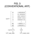
- FIG. 3 illustrates an example of a lookup table (LUT) used for an operation of a primitive polynomial in a Galois field using a conventional syndrome calculation method.
- LUT lookup table
- FIG. 5 illustrates an example of a high-order syndrome calculator.
- FIG. 6 illustrates a detailed example of a high-order syndrome calculator.
- FIG. 8 illustrates another example of a high-order syndrome calculator.
- FIG. 9 illustrates an example of a method of calculating a high-order syndrome.
- FIG. 10 illustrates another example of a method of calculating a high-order syndrome.
- FIG. 11 illustrates an example of a table showing a result of comparing a calculation complexity using a conventional syndrome calculation method and a calculation complexity using a high-order syndrome calculation method disclosed in this application.
- An error correcting code is a technology capable of improving communication reliability in a digital communication system. For example, due to various non-ideal communication channel environments, for example, random noise, an error may occur in bit information received by a receiver.
- the receiver may detect and correct an error using an error correcting code and a transmitter may recover bit information that is to be transmitted, thereby enhancing the communication reliability.
- An error correcting code may be divided into a block code and a convolutional code.
- the block code is a basic code that is widely used and is encoded based on a block unit of a predetermined length.
- the block code configures an encoded bit sequence of a predetermined length by adding a redundant bit called a parity bit to message bit information of a predetermined length that is to be transmitted.
- a Hamming code a most basic block code, is a block code having an error correcting capability of one bit.
- the Hamming code can correct an error when a single bit error occurs in a bit sequence of a single block received from the transmitter, but cannot correct an error properly when an error occurs in two or more bits.
- a Bose-Chaudhuri-Hocquenghem (BCH) code can correct errors in two or more bits using a variety of parameters.
- the Hamming code may be regarded as a single type of the BCH code.
- a Reed-Solomon (RS) code treats a plurality of bits as a single symbol and performs signal processing based on a symbol unit.
- the RS code may treat a plurality of bits as a single symbol and configure a predetermined number of symbols as a single block.
- the RS code may perform encoding and decoding based on a symbol unit and may perform error correction based on a predetermined number of symbol units. When a plurality of bits is present in a single symbol, the RS code may correct an error based on a symbol unit. Therefore, the RS code may be robust against a burst error in which errors occur in adjacent bits.
- FIG. 1 illustrates an example of a channel encoder 100 configured to encode a block code in a transmitter.
- the channel encoder 100 configures a total of n sequence blocks by appropriately adding (n ⁇ k) parity bits corresponding to redundant bits to k message bits corresponding to original bit information, and transmits the n sequence blocks to a receiver.
- the n bit sequence blocks transmitted by the channel encoder 100 using the above method are referred to as a (n, k) block code, and an n-bit sequence that is output from the channel encoder 100 is referred to as a codeword.
- k message bits in the n-bit sequence are transmitted without being modified and by adding (n ⁇ k) parity bits, and thus the n-bit sequence is referred to as a systematic code.
- the receiver receives and decodes a bit sequence encoded by the channel encoder 100 . A channel decoder of the receiver is described with reference to FIG. 2 .
- FIG. 2 illustrates an example of a channel decoder 200 configured to decode a block code in a receiver.
- a bit sequence demodulated to “ 0 ” or “ 1 ” through a demodulator is input to the channel decoder 200 . Due to some non-ideal communication channel environments, for example, noise, an error bit may be present in the demodulated bit sequence.
- the channel decoder 200 corrects an error by appropriately performing signal processing on n demodulated bit sequences and acquires k decoded output bit sequences.
- an output bit sequence will differ from an original bit sequence transmitted from a transmitter.
- the channel decoder 200 includes a syndrome calculator 210 , an error location calculator 230 , and an error corrector 250 .
- the syndrome calculator 210 calculates a syndrome value.
- syndrome value refers to a value used as a determination standard capable of verifying whether an error is present in a bit sequence transmitted from the transmitter to the receiver. For example, a syndrome value is not zero indicates the occurrence of an error, and thus the receiver may perform signal processing to correct the error.
- a location of a bit in which the error has occurred in the entire bit sequence needs to be known.
- the bit may be corrected.
- the error location calculator 230 calculates the location of the bit in which the error has occurred.
- a syndrome value may be used to calculate the location of the bit in which the error has occurred.
- the error corrector 250 corrects the error of the bit at the location of the bit calculated by the error location calculator 230 .
- the error corrector 250 may correct a bit in which an error has occurred from “ 1 ” to “ 0 ”, or may correct the bit from “ 0 ” to “ 1 ”.
- S j a syndrome order
- S j a syndrome order
- the calculation complexity may further increase.
- the Galois field may be represented as GF(p m ) by a prime number p and a positive integer m, and may also be referred to as a finite field since the Galois field has a finite number of elements.
- a primitive element and a primitive polynomial used in the Galois field may be defined as follows.
- ⁇ GF(q) is referred as a primitive element of the finite field GF(q).
- All the constituent elements, excluding “ 0 ”, of the finite field GF(q) may represent a positive integer n as ⁇ n .
- a polynomial f(x) having a coefficient in GF(p) has a degree of m and has root a satisfying ⁇ 0, 1, ⁇ , ⁇ 2 , . . . , ⁇ (p m ⁇ 2) ⁇ in GF(p m )
- Table 1 shows GF(2 6 ) constituent elements generated based on the primitive polynomial “1+x+x 6 ”.
- the first column is a power representation that represents a multiplier of a primitive element ⁇
- the second column is a polynomial representation that represents the same element of the first column as
- ⁇ l 0 m - 1 ⁇ c l ⁇ ⁇ l ⁇ c l denotes a coefficient having a value of “ 0 ” or “ 1 ”.
- the third column is a vector representation that represents values of C l in a vector form such as [C 0 C 1 C 2 C 3 C 4 C 5 ].
- LUT lookup table
- FIG. 3 illustrates an example of a LUT used for an operation of a primitive polynomial in a Galois field using a conventional syndrome calculation method.
- a process of calculating a syndrome corresponds to a signal processing process that is initially performed when decoding a block code.
- a syndrome value that is not “ 0 ” indicates that an error correction is required due to the occurrence of an error in received bits.
- bxor(l) denotes an I th value of bxor that is a vector including m bits, and bxor may be obtained as follows:
- a process of calculating a syndrome of S 3 corresponds to a process of calculating ⁇ i of a gradually increasing multiplier and adding up the calculation results.
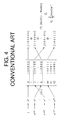
- a process of calculating a syndrome of S 3 using the conventional syndrome calculation method may be expressed as illustrated in FIG. 4 .
- the conventional syndrome calculation method when calculating a multiplier value of a of the first column, performs a process of multiplying an index of a bit sequence by a value corresponding to a syndrome order.
- the conventional syndrome calculation method performs a modulo-(2 m ⁇ 1), that is, modulo-63 operation on the calculated multiplier.
- a modulo-(2 m ⁇ 1) that is, modulo-63 operation on the calculated multiplier.
- the conventional syndrome calculation method performs a process of obtaining an output vector of a LUT (LUT_output_vector) when the multiplier value of ⁇ obtained after performing the modulo-63 operation is used as an input value, and outputting the obtained output value.
- XOR bitwise exclusive OR
- the conventional syndrome calculation method uses a multiplication and a modulo operation.
- the conventional syndrome calculation method uses a storage space to store a large size of bit information to construct a LUT.
- the conventional syndrome calculation method needs to perform a continuous search process of finding, using an input index, storage information that maps the input index. Accordingly, a LUT function call is frequently performed. The frequent LUT function increases an operation complexity and an amount of power consumption.
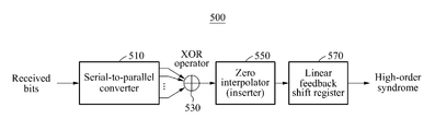
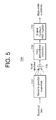
- FIG. 5 illustrates an example of a high-order syndrome calculator 500 .
- the high-order syndrome calculator 500 includes a serial-to-parallel converter 510 , an XOR operator 530 , a zero interpolator (inserter) 550 , and a linear feedback shift register 570 .
- the serial-to-parallel converter 510 converts serial bit sequences received from a transmitter to a parallel multi-stream.
- L denotes a natural number satisfying L ⁇ 1
- D denotes the predetermined number of bits
- n denotes a block size of a block code
- j denotes a syndrome order to be calculated
- n/j denotes an integer.
- the XOR operator 530 performs an XOR operation on bit values of the converted multi-stream. For example, when a first multi-stream is [a 0 a 1 a 2 a 3 a 4 a 5 ] and a second multi-stream is [b 0 b 1 b 2 b 3 b 4 b 5 ], the XOR operator 530 performs an XOR operation on bit values as expressed by [a 0 ⁇ b 0 a 1 ⁇ b 1 a 2 ⁇ b 2 a 3 ⁇ b 3 a 4 ⁇ b 4 a 5 ⁇ b 5 ].
- ⁇ denotes an XOR operation, for example, a modulo-2 operation.
- the zero interpolator (inserter) 550 inserts zero values between the bits on which the XOR operation is performed.
- the linear feedback shift register 570 calculates a high-order syndrome value based on a coefficient of a remainder obtained by dividing, by a primitive polynomial, a polynomial generated from the multi-stream in which the zero values are inserted.
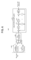
- FIG. 6 illustrates a detailed example of a high-order syndrome calculator 600 .
- the high-order syndrome calculator 600 includes a serial-to-parallel converter 610 , an XOR operator 630 , a zero interpolator (inserter) 650 , and a linear feedback shift register 670 .
- serial bit sequences received from a transmitter pass through the serial-to-parallel converter 610 .
- the serial-to-parallel converter 610 includes (L ⁇ 1) delay elements 611 .
- a delay element may be a register corresponding to a flip-flop or a unit-delay element.
- the serial-to-parallel converter 610 outputs an input bit sequence as a first bit of a multi-stream without delaying the bit sequence, and outputs a bit sequence as an L th bit of the multi-stream after delaying the bit sequence by (L ⁇ 1) ⁇ D bits.
- the serial-to-parallel converter 610 converts serial bit sequences to an L-bit multi-stream
- the serial-to-parallel converter 610 includes L parallel paths, delays the received serial bit sequences by an amount of time corresponding to integer multiples of the predetermined number of bits with respect to L parallel paths, and inputs the delayed serial bit sequences.
- a received bit sequence is output without being delayed.
- the bit sequence is delayed by D bits compared to the first path and output.
- the bit sequence is delayed by 2D bits compared to the first path and output.
- the bit sequence is delayed by (L ⁇ 1) ⁇ D bits compared to the first path and output.
- the XOR operator 630 performs an XOR operation on bit values of the multi-stream.
- N the number of bits of the multi-stream on which the XOR operation is performed.
- the multi-stream in which zero values are inserted is used as an input of the linear feedback shift register 670 .
- Each of flip-flops (FF) 673 may be replaced with a register corresponding to a unit-delay element.
- ⁇ l may have a value of “ 0 ” or “1”.
- ⁇ l denotes a coefficient of a primitive polynomial ⁇ (x) having a degree of m
- ⁇ l 1 m ⁇ lfsr ⁇ ( l ) ⁇ ⁇ l - 1 that includes coefficients of lfsr(l).
- the linear feedback shift register 670 is configured to output a result corresponding to a remainder obtained by dividing an input polynomial by a primitive polynomial ⁇ (x).
- a value stored in each FF 673 at a point in time in which the linear feedback shift register 670 receives all the input sequences corresponds to a coefficient of a remainder polynomial obtained when dividing the input polynomial by ⁇ (x).
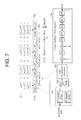
- Equation 2 the entire operation of calculating S 3 may be expressed by the following Equation 2.
- a process of delaying input serial bit sequences as expressed by the first equation of S 3 by integer multiples of a predetermined number of bits and outputting the delayed bit sequences on parallel paths is performed by a serial-to-parallel converter 710 .
- An XOR operation on bit values of the multi-stream in the second equation 701 of S 3 is performed by the XOR operator 730 .
- the serial-to-parallel converter 710 processes the bits so that a bit stream is received sequentially in order of r 62 , r 61 , r 60 , . . . , r 44 , r 43 , r 42 in a first path, a bit stream delayed by 21 samples compared to the first path, i.e., r 41 , r 40 , r 39 , . . .
- the XOR operator 730 performs an XOR operation on bit values of streams input in parallel every time new bits are input and outputs a result of the XOR operation.
- a multiplier value of ⁇ i increases by “3”, and thus a zero interpolator 750 inserts terms of ⁇ i between the values of the second equation 701 as expressed by an equation 703 .
- coefficients of the inserted terms ⁇ i are set to “ 0 ”.
- the zero interpolator 750 inserts terms each having a coefficient of zero due to the following reasons.
- signal processing of calculating a polynomial c(x) corresponding to a remainder obtained when dividing a predetermined polynomial a(x) by another polynomial b(x) in the Galois field may be easily performed by a linear feedback shift register 770 .
- a sequence for example, a multi-stream applied as an input of the linear feedback shift register 770 , is a sequence that includes coefficients of x i of the polynomial a(x).
- the linear feedback shift register 770 may calculate a remainder polynomial R( ⁇ ) based on a value finally stored in an FF.
- the zero interpolator 750 inserts ⁇ i terms having zeros as coefficients as expressed by the second equation 703 to input the sequence corresponding to the coefficient of x i without omission of any coefficients.
- the linear feedback shift register 770 calculates S 3 based on values finally stored in FFs.
- the linear feedback shift register 770 obtains information of a polynomial, for example, a coefficient of a polynomial corresponding to a remainder obtained when dividing, by a primitive polynomial, an input polynomial in which zero values are inserted.
- a value applied as the input of the linear feedback shift register 770 is a bit sequence corresponding to a coefficient of term ⁇ i in a polynomial form.
- the high-order syndrome calculator may be applied substantially similarly to a non-binary code, for example, an RS code.
- a non-binary code for example, an RS code.
- signal processing is performed based on a symbol unit including a plurality of bits, for example, m bits, instead of based on a single bit unit.
- a signal may be input to the serial-to-parallel converter 710 and the zero interpolator 750 may insert N zero symbols.
- a single zero symbol may include m zero bits. Symbols including m bits may be stored in FFs included in the linear feedback shift register 770 .
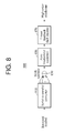
- FIG. 8 illustrates another example of a high-order syndrome calculator 800 .
- the high-order syndrome calculator 800 is configured to calculate a syndrome value for bit sequences configured based on a symbol unit.
- the high-order syndrome calculator 800 includes a serial-to-parallel converter 810 , an XOR operator 830 , a zero interpolator 850 , and a linear feedback shift register 870 .
- the serial-to-parallel converter 810 converts serial bit sequences received from a transmitter to a parallel multi-stream configured based on a symbol unit.
- the symbol unit includes a plurality of bits.
- Symbol unit denotes a number of bits in one symbol unit
- L denotes a natural number satisfying L ⁇ 1
- D denotes the predetermined number of bits
- n denotes a block size of a block code
- j denotes a syndrome order to be calculated
- n/j denotes an integer.
- (symbol unit ⁇ L)-bit denotes a number of bits in L symbol units.
- the serial-to-parallel converter 810 When a value of n/j is not an integer, the serial-to-parallel converter 810 outputs the received serial bit sequences to the zero interpolator 850 without delaying the received serial bit sequences.
- the XOR operator 830 performs an XOR operation on bit values of the parallel multi-stream based on the symbol unit.
- the zero interpolator 850 inserts zero values between the bits of the multi-stream on which the XOR operation is performed.
- the linear feedback shift register 870 calculates a high-order syndrome value based on a coefficient of a remainder obtained by dividing, by a primitive polynomial, a polynomial generated from the multi-stream in which the zero values are inserted.
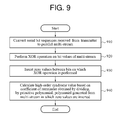
- FIG. 9 illustrates an example of a method of calculating a high-order syndrome.
- a high-order syndrome calculator (hereinafter, a calculator) converts serial bit sequences received from a transmitter to a parallel multi-stream.
- the calculator performs an XOR operation on bit values of the multi-stream.
- the calculator inserts zero values between the bits on which the XOR operation is performed.
- the calculator calculates a high-order syndrome value based on a coefficient of a remainder obtained by dividing, by a primitive polynomial, a polynomial generated from the multi-stream in which the zero values are inserted.
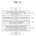
- FIG. 10 illustrates another example of a method of calculating a high-order syndrome.
- a high-order syndrome calculator (hereinafter, a calculator) converts serial bit sequences received from a transmitter to a parallel multi-stream configured based on a symbol unit.
- the symbol unit includes a plurality of bits.
- the calculator performs an XOR operation on bit values of the multi-stream based on the symbol unit.
- the XOR operation based on the symbol unit is performed for each bit of a symbol.
- the calculator inserts zero values between the bits of the multi-stream on which the XOR operation is performed.
- the calculator calculates a high-order syndrome value based on a coefficient of a remainder obtained by dividing, by a primitive polynomial, a polynomial generated from the multi-stream in which the zero values are inserted.
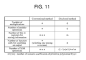
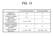
- FIG. 11 illustrates an example of a table showing a result of comparing a calculation complexity using a conventional syndrome calculation method and a calculation complexity using a high-order syndrome calculation method disclosed in this application.
- the number of modulo operations is n
- the number of bits in registers for storing information and the number of XOR operations are each m ⁇ n.
- the number of LUT function calls for searching for an output value is also n.
- the disclosed high-order calculation method does not use a storage space of a register for configuring a LUT and does not use a LUT function call for searching for an output value.
- the disclosed high-order calculation method uses m bits in registers to configure a linear feedback shift register and performs ((L ⁇ 1) ⁇ (n/L)+m′ ⁇ n) XOR operations.
- m′ denotes a number of nonzero coefficients of a primitive polynomial f(x) ⁇ 1.
- the number of LUT function calls for searching for an output value is also “63”.
- the disclosed high-order calculation method does not use a storage space of a register for configuring a LUT and does not use a LUT function call for searching for an output value.
- the parity bit calculator and the systematic codeword constructor in FIG. 1 , the syndrome calculator 210 , the error location calculator 230 , and the error corrector 250 in FIG. 2 , the series-to-parallel converters 510 , 610 , 710 , and 810 , the XOR operators 530 , 630 , 730 , and 830 , the zero interpolators 550 , 650 , 750 , and 850 , and the linear feedback shift registers 570 , 670 , 770 , and 870 in FIGS. 5-8 that perform the various operations described with respect to FIGS. 1, 2, and 5-12 may be implemented using one or more hardware components, one or more software components, or a combination of one or more hardware components and one or more software components.
- a hardware component may be, for example, a physical device that physically performs one or more operations, but is not limited thereto.
- hardware components include resistors, capacitors, inductors, power supplies, frequency generators, operational amplifiers, power amplifiers, low-pass filters, high-pass filters, band-pass filters, analog-to-digital converters, digital-to-analog converters, and processing devices.
- a software component may be implemented, for example, by a processing device controlled by software or instructions to perform one or more operations, but is not limited thereto.
- a computer, controller, or other control device may cause the processing device to run the software or execute the instructions.
- One software component may be implemented by one processing device, or two or more software components may be implemented by one processing device, or one software component may be implemented by two or more processing devices, or two or more software components may be implemented by two or more processing devices.
- a processing device may be implemented using one or more general-purpose or special-purpose computers, such as, for example, a processor, a controller and an arithmetic logic unit, a digital signal processor, a microcomputer, a field-programmable array, a programmable logic unit, a microprocessor, or any other device capable of running software or executing instructions.
- the processing device may run an operating system (OS), and may run one or more software applications that operate under the OS.
- the processing device may access, store, manipulate, process, and create data when running the software or executing the instructions.
- OS operating system
- the singular term “processing device” may be used in the description, but one of ordinary skill in the art will appreciate that a processing device may include multiple processing elements and multiple types of processing elements.
- a processing device may include one or more processors, or one or more processors and one or more controllers.
- different processing configurations are possible, such as parallel processors or multi-core processors.
- a processing device configured to implement a software component to perform an operation A may include a processor programmed to run software or execute instructions to control the processor to perform operation A.
- a processing device configured to implement a software component to perform an operation A, an operation B, and an operation C may have various configurations, such as, for example, a processor configured to implement a software component to perform operations A, B, and C; a first processor configured to implement a software component to perform operation A, and a second processor configured to implement a software component to perform operations B and C; a first processor configured to implement a software component to perform operations A and B, and a second processor configured to implement a software component to perform operation C; a first processor configured to implement a software component to perform operation A, a second processor configured to implement a software component to perform operation B, and a third processor configured to implement a software component to perform operation C; a first processor configured to implement a software component to perform operations A, B, and C, and a second processor configured to implement a software component to perform operations A, B
- Software or instructions for controlling a processing device to implement a software component may include a computer program, a piece of code, an instruction, or some combination thereof, for independently or collectively instructing or configuring the processing device to perform one or more desired operations.
- the software or instructions may include machine code that may be directly executed by the processing device, such as machine code produced by a compiler, and/or higher-level code that may be executed by the processing device using an interpreter.
- the software or instructions and any associated data, data files, and data structures may be embodied permanently or temporarily in any type of machine, component, physical or virtual equipment, computer storage medium or device, or a propagated signal wave capable of providing instructions or data to or being interpreted by the processing device.
- the software or instructions and any associated data, data files, and data structures also may be distributed over network-coupled computer systems so that the software or instructions and any associated data, data files, and data structures are stored and executed in a distributed fashion.
- the software or instructions and any associated data, data files, and data structures may be recorded, stored, or fixed in one or more non-transitory computer-readable storage media.
- a non-transitory computer-readable storage medium may be any data storage device that is capable of storing the software or instructions and any associated data, data files, and data structures so that they can be read by a computer system or processing device.
- Examples of a non-transitory computer-readable storage medium include read-only memory (ROM), random-access memory (RAM), flash memory, CD-ROMs, CD-Rs, CD+Rs, CD-RWs, CD+RWs, DVD-ROMs, DVD-Rs, DVD+Rs, DVD-RWs, DVD+RWs, DVD-RAMs, BD-ROMs, BD-Rs, BD-R LTHs, BD-REs, magnetic tapes, floppy disks, magneto-optical data storage devices, optical data storage devices, hard disks, solid-state disks, or any other non-transitory computer-readable storage medium known to one of ordinary skill in the art.
- ROM read-only memory
- RAM random-access memory
- flash memory CD-ROMs, CD-Rs, CD+Rs, CD-RWs, CD+RWs, DVD-ROMs, DVD-Rs, DVD+Rs, DVD-RWs, DVD+RWs, DVD-RAMs, BD
- a transmitter or a receiver described herein may refer to a mobile device such as a cellular phone, a personal digital assistant (PDA), a digital camera, a portable game console, an MP3 player, a portable/personal multimedia player (PMP), a handheld e-book, a portable laptop PC, a global positioning system (GPS) navigation device, a tablet, or a sensor, or a stationary device such as a desktop PC, a high definition television (HDTV), an optical disc player, a set-top box, or a home appliance, or any other device known to one of ordinary skill in the art that is capable of wireless communication or network communication consistent with that which is disclosed herein.
- a mobile device such as a cellular phone, a personal digital assistant (PDA), a digital camera, a portable game console, an MP3 player, a portable/personal multimedia player (PMP), a handheld e-book, a portable laptop PC, a global positioning system (GPS) navigation device, a tablet, or a sensor, or a
Abstract
Description
based on the definitions made above, equations of α2
| TABLE 1 | |||
| Power | Polynomial | Vector | |
| | representation | representation | |
| 0 | 0 | [0 0 0 0 0 0] | |
| 1 | 1 | [1 0 0 0 0 0] | |
| |
0 + α | [0 1 0 0 0 0] | |
| |
0 + 0 + α2 | [0 0 1 0 0 0] | |
| |
0 + 0 + 0 + α3 | [0 0 0 1 0 0] | |
| |
0 + 0 + 0 + 0 + α4 | [0 0 0 0 1 0] | |
| |
0 + 0 + 0 + 0 + 0 + α5 | [0 0 0 0 0 1] | |
| |
1 + α | [1 1 0 0 0 0] | |
| |
0 + α + α2 | [0 1 1 0 0 0] | |
| . . . | . . . | . . . | |
| |
1 + 0 + 0 + 0 + α4 + α5 | [1 0 0 0 1 1] | |
| |
1 + 0 + 0 + 0 + 0 + α5 | [1 0 0 0 0 1] | |
denotes a coefficient having a value of “0” or “1”.
S j =r(αj) [Equation 1]
is satisfied.
that includes coefficients of lfsr(l).
is obtained.
Claims (15)
Applications Claiming Priority (4)
| Application Number | Priority Date | Filing Date | Title |
|---|---|---|---|
| KR10-2014-0030490 | 2014-03-14 | ||
| KR20140030490 | 2014-03-14 | ||
| KR10-2014-0089739 | 2014-07-16 | ||
| KR1020140089739A KR102118605B1 (en) | 2014-03-14 | 2014-07-16 | Low complexity high order syndrome calculator for block codes and calculating method of high order syndrome |
Publications (2)
| Publication Number | Publication Date |
|---|---|
| US20150263764A1 US20150263764A1 (en) | 2015-09-17 |
| US9467174B2 true US9467174B2 (en) | 2016-10-11 |
Family
ID=54070142
Family Applications (1)
| Application Number | Title | Priority Date | Filing Date |
|---|---|---|---|
| US14/500,803 Active 2035-02-07 US9467174B2 (en) | 2014-03-14 | 2014-09-29 | Low complexity high-order syndrome calculator for block codes and method of calculating high-order syndrome |
Country Status (2)
| Country | Link |
|---|---|
| US (1) | US9467174B2 (en) |
| CN (1) | CN104917535B (en) |
Families Citing this family (1)
| Publication number | Priority date | Publication date | Assignee | Title |
|---|---|---|---|---|
| KR102359265B1 (en) * | 2015-09-18 | 2022-02-07 | 삼성전자주식회사 | Processing apparatus and method for performing operation thereof |
Citations (18)
| Publication number | Priority date | Publication date | Assignee | Title |
|---|---|---|---|---|
| WO1985001625A1 (en) | 1983-09-27 | 1985-04-11 | Cyclotomics, Inc. | Error correction for algebraic block codes |
| JPH05224967A (en) | 1992-02-15 | 1993-09-03 | Mitsubishi Electric Corp | Error correcting device |
| JPH07254860A (en) | 1994-03-16 | 1995-10-03 | Nec Corp | Error correction decoding device |
| US5600582A (en) * | 1994-04-05 | 1997-02-04 | Texas Instruments Incorporated | Programmable horizontal line filter implemented with synchronous vector processor |
| KR19980041383A (en) | 1996-11-30 | 1998-08-17 | 배순훈 | Parallel Traversal Redundancy Code Encoder and Decoder |
| JP2874933B2 (en) | 1990-02-06 | 1999-03-24 | 富士通株式会社 | Digital signal error correction processing device and error correction processing method thereof |
| KR100192803B1 (en) | 1996-11-29 | 1999-06-15 | 전주범 | Apparatus for computing error correction syndromes |
| KR100212829B1 (en) | 1996-02-29 | 1999-08-02 | 전주범 | Syndrome calculating apparatus of reed solomon decoder |
| JP2001136078A (en) | 1999-11-05 | 2001-05-18 | Matsushita Electric Ind Co Ltd | Syndrome arithmetic method and device |
| JP3223513B2 (en) | 1991-01-16 | 2001-10-29 | 三菱電機株式会社 | Error correction decoding device |
| US6597745B1 (en) * | 1999-04-06 | 2003-07-22 | Eric M. Dowling | Reduced complexity multicarrier precoder |
| US20030140302A1 (en) * | 2002-01-23 | 2003-07-24 | Litwin, Louis Robert | Chien search cell for an error-correcting decoder |
| KR20040041294A (en) | 2002-11-09 | 2004-05-17 | 조용석 | A Divisionless Decoding Method and Decoder for the BCH Codes |
| JP2006340205A (en) | 2005-06-03 | 2006-12-14 | Sharp Corp | Error correction device |
| US20080080598A1 (en) * | 2006-09-29 | 2008-04-03 | Shaomin Samuel Mo | Method and apparatus for processing communication using different modulation schemes |
| JP2008112522A (en) | 2006-10-31 | 2008-05-15 | Fujitsu Ltd | Device and method for detecting error |
| US20080133630A1 (en) * | 2006-12-01 | 2008-06-05 | Electronics And Telecommunications Research Institute | Interpolation fir filter having multiple data rates in mobile communication system and method of filtering data using the same |
| US8416019B2 (en) * | 2009-08-14 | 2013-04-09 | That Corporation | System and method for interpolating digitally-controlled amplifier gain |
Family Cites Families (4)
| Publication number | Priority date | Publication date | Assignee | Title |
|---|---|---|---|---|
| JPH11196006A (en) * | 1997-12-26 | 1999-07-21 | Nec Corp | Parallel processing syndrome calculation circuit and reed solomon decoding circuit |
| CN101834615B (en) * | 2009-03-12 | 2012-12-26 | 高通创锐讯通讯科技(上海)有限公司 | Implementation method of Reed-Solomon encoder |
| US8347192B1 (en) * | 2010-03-08 | 2013-01-01 | Altera Corporation | Parallel finite field vector operators |
| TWI426715B (en) * | 2010-05-07 | 2014-02-11 | Univ Ishou | Error detection decoding module and error detection correction device |
-
2014
- 2014-09-29 US US14/500,803 patent/US9467174B2/en active Active
- 2014-12-30 CN CN201410840383.3A patent/CN104917535B/en active Active
Patent Citations (18)
| Publication number | Priority date | Publication date | Assignee | Title |
|---|---|---|---|---|
| WO1985001625A1 (en) | 1983-09-27 | 1985-04-11 | Cyclotomics, Inc. | Error correction for algebraic block codes |
| JP2874933B2 (en) | 1990-02-06 | 1999-03-24 | 富士通株式会社 | Digital signal error correction processing device and error correction processing method thereof |
| JP3223513B2 (en) | 1991-01-16 | 2001-10-29 | 三菱電機株式会社 | Error correction decoding device |
| JPH05224967A (en) | 1992-02-15 | 1993-09-03 | Mitsubishi Electric Corp | Error correcting device |
| JPH07254860A (en) | 1994-03-16 | 1995-10-03 | Nec Corp | Error correction decoding device |
| US5600582A (en) * | 1994-04-05 | 1997-02-04 | Texas Instruments Incorporated | Programmable horizontal line filter implemented with synchronous vector processor |
| KR100212829B1 (en) | 1996-02-29 | 1999-08-02 | 전주범 | Syndrome calculating apparatus of reed solomon decoder |
| KR100192803B1 (en) | 1996-11-29 | 1999-06-15 | 전주범 | Apparatus for computing error correction syndromes |
| KR19980041383A (en) | 1996-11-30 | 1998-08-17 | 배순훈 | Parallel Traversal Redundancy Code Encoder and Decoder |
| US6597745B1 (en) * | 1999-04-06 | 2003-07-22 | Eric M. Dowling | Reduced complexity multicarrier precoder |
| JP2001136078A (en) | 1999-11-05 | 2001-05-18 | Matsushita Electric Ind Co Ltd | Syndrome arithmetic method and device |
| US20030140302A1 (en) * | 2002-01-23 | 2003-07-24 | Litwin, Louis Robert | Chien search cell for an error-correcting decoder |
| KR20040041294A (en) | 2002-11-09 | 2004-05-17 | 조용석 | A Divisionless Decoding Method and Decoder for the BCH Codes |
| JP2006340205A (en) | 2005-06-03 | 2006-12-14 | Sharp Corp | Error correction device |
| US20080080598A1 (en) * | 2006-09-29 | 2008-04-03 | Shaomin Samuel Mo | Method and apparatus for processing communication using different modulation schemes |
| JP2008112522A (en) | 2006-10-31 | 2008-05-15 | Fujitsu Ltd | Device and method for detecting error |
| US20080133630A1 (en) * | 2006-12-01 | 2008-06-05 | Electronics And Telecommunications Research Institute | Interpolation fir filter having multiple data rates in mobile communication system and method of filtering data using the same |
| US8416019B2 (en) * | 2009-08-14 | 2013-04-09 | That Corporation | System and method for interpolating digitally-controlled amplifier gain |
Non-Patent Citations (4)
| Title |
|---|
| L. Li, "Linear-feedback shift registers for encoding and decoding cyclic codes," Section 4 of Notes to Error Control Code, Apr. 1, 2007, notes for undergraduate students majoring in telecommunications, College of Mathematics, Science, and Information, Shanghai Normal University (SHNU), Shanghai, China (19 pages, in English). |
| S. Haykin, Communications Systems, 4th Edition, 2001, John Wiley & Sons, Inc. (entire book, 838 pages). |
| Sukhavasi et al., A Primitive Polynomial to Define the Finite Field Modules for High-Throughput Interpolator to Encode and Decode of Non Binary Cyclic Codes, Jul.-Aug. 2012, International Journal of Modern Engineering Research (IJMER), vol. 2, Issue.4, pp. 2938-2946. * |
| X. Zhang et al., "Interpolation-based Hard-decision Reed-Solomon Decoders," Proceedings of the 12th International Symposium on Integrated Circuits (ISIC 2009), Dec. 2009, pp. 175-178, conference held Dec. 14-16, 2009, Singapore. |
Also Published As
| Publication number | Publication date |
|---|---|
| CN104917535B (en) | 2019-10-25 |
| CN104917535A (en) | 2015-09-16 |
| US20150263764A1 (en) | 2015-09-17 |
Similar Documents
| Publication | Publication Date | Title |
|---|---|---|
| US10243589B2 (en) | Multi-bit error correction method and apparatus based on a BCH code and memory system | |
| US8650466B2 (en) | Incremental generation of polynomials for decoding reed-solomon codes | |
| US8880973B1 (en) | Detector-decoder interface for GF(q) iterative decoding | |
| US9344117B2 (en) | Methods and systems for error-correction decoding | |
| JP7012479B2 (en) | Reed-Solomon Decoder and Decoding Method | |
| CN110971243B (en) | System and method for decoding BCH encoded codewords | |
| Das et al. | Design of RS (255, 251) Encoder and Decoder in FPGA | |
| CN108886369B (en) | Method and apparatus for performing Reed-Solomon coding | |
| EP1102406A2 (en) | Apparatus and method for decoding digital data | |
| KR102241416B1 (en) | Apparatus and method for decoding low density parity check(ldpc) codes in digital video broadcasting(dvb) system | |
| US9467174B2 (en) | Low complexity high-order syndrome calculator for block codes and method of calculating high-order syndrome | |
| WO2011154750A1 (en) | Decoding of reed - solomon codes using look-up tables for error detection and correction | |
| KR101432909B1 (en) | HIGH-SPEED LOW-COMPELEXITY MODIFIED STEP-BY-STEP DECODING METHOD AND Circuit for parallel bch decoder | |
| GB2523586A (en) | Method and a device for decoding a bitstream encoded with an outer convolutional code and an inner block code | |
| US9287898B2 (en) | Method and circuit for shortening latency of Chien'S search algorithm for BCH codewords | |
| US20180006664A1 (en) | Methods and apparatus for performing reed-solomon encoding by lagrangian polynomial fitting | |
| US8042026B2 (en) | Method for efficiently calculating syndromes in reed-solomon decoding, and machine-readable storage medium storing instructions for executing the method | |
| US20180316364A1 (en) | Methods, systems, and computer-readable media for decoding a cyclic code | |
| KR102118605B1 (en) | Low complexity high order syndrome calculator for block codes and calculating method of high order syndrome | |
| US8296632B1 (en) | Encoding and decoding of generalized Reed-Solomon codes using parallel processing techniques | |
| Hurtic et al. | Hard-decision staircase decoder in 28-nm fully-depleted silicon-on-insulator | |
| Jin | Design and implementation of efficient Reed-Solomon decoder for intelligent home networking | |
| Sezer | Asic Implementation of High-Throughput Reed-Solomon Product Codes | |
| Kaur | Comparative Analysis of Error Correcting Codes for Noisy Channel | |
| Balamurugan et al. | Novel Error Detection and Correction in Memory System using Hybrid Technology |
Legal Events
| Date | Code | Title | Description |
|---|---|---|---|
| AS | Assignment |
Owner name: SAMSUNG ELECTRONICS CO., LTD., KOREA, REPUBLIC OF Free format text: ASSIGNMENT OF ASSIGNORS INTEREST;ASSIGNORS:PARK, CHANG SOON;HWANG, HYO SUN;HONG, YOUNG JUN;REEL/FRAME:033845/0003 Effective date: 20140915 |
|
| STCF | Information on status: patent grant |
Free format text: PATENTED CASE |
|
| FEPP | Fee payment procedure |
Free format text: PAYOR NUMBER ASSIGNED (ORIGINAL EVENT CODE: ASPN); ENTITY STATUS OF PATENT OWNER: LARGE ENTITY |
|
| MAFP | Maintenance fee payment |
Free format text: PAYMENT OF MAINTENANCE FEE, 4TH YEAR, LARGE ENTITY (ORIGINAL EVENT CODE: M1551); ENTITY STATUS OF PATENT OWNER: LARGE ENTITY Year of fee payment: 4 |
|
| MAFP | Maintenance fee payment |
Free format text: PAYMENT OF MAINTENANCE FEE, 8TH YEAR, LARGE ENTITY (ORIGINAL EVENT CODE: M1552); ENTITY STATUS OF PATENT OWNER: LARGE ENTITY Year of fee payment: 8 |