US9427085B2 - Chair arm assembly - Google Patents
Chair arm assembly Download PDFInfo
- Publication number
- US9427085B2 US9427085B2 US14/624,899 US201514624899A US9427085B2 US 9427085 B2 US9427085 B2 US 9427085B2 US 201514624899 A US201514624899 A US 201514624899A US 9427085 B2 US9427085 B2 US 9427085B2
- Authority
- US
- United States
- Prior art keywords
- assembly
- arm
- chair
- linkage
- pivot
- Prior art date
- Legal status (The legal status is an assumption and is not a legal conclusion. Google has not performed a legal analysis and makes no representation as to the accuracy of the status listed.)
- Active
Links
- 230000000712 assembly Effects 0.000 description 22
- 238000000429 assembly Methods 0.000 description 22
- 210000004705 lumbosacral region Anatomy 0.000 description 12
- 230000008859 change Effects 0.000 description 9
- 230000002787 reinforcement Effects 0.000 description 6
- 239000000758 substrate Substances 0.000 description 5
- UQMRAFJOBWOFNS-UHFFFAOYSA-N butyl 2-(2,4-dichlorophenoxy)acetate Chemical compound CCCCOC(=O)COC1=CC=C(Cl)C=C1Cl UQMRAFJOBWOFNS-UHFFFAOYSA-N 0.000 description 4
- 230000008878 coupling Effects 0.000 description 4
- 238000010168 coupling process Methods 0.000 description 4
- 238000005859 coupling reaction Methods 0.000 description 4
- 230000007935 neutral effect Effects 0.000 description 4
- 229920002725 thermoplastic elastomer Polymers 0.000 description 4
- 230000007246 mechanism Effects 0.000 description 3
- NJPPVKZQTLUDBO-UHFFFAOYSA-N novaluron Chemical compound C1=C(Cl)C(OC(F)(F)C(OC(F)(F)F)F)=CC=C1NC(=O)NC(=O)C1=C(F)C=CC=C1F NJPPVKZQTLUDBO-UHFFFAOYSA-N 0.000 description 3
- 230000001154 acute effect Effects 0.000 description 2
- 230000008901 benefit Effects 0.000 description 2
- 230000006835 compression Effects 0.000 description 2
- 238000007906 compression Methods 0.000 description 2
- 239000006260 foam Substances 0.000 description 2
- 230000006870 function Effects 0.000 description 2
- 210000004394 hip joint Anatomy 0.000 description 2
- 239000000463 material Substances 0.000 description 2
- 238000000034 method Methods 0.000 description 2
- 230000004048 modification Effects 0.000 description 2
- 238000012986 modification Methods 0.000 description 2
- 239000004033 plastic Substances 0.000 description 2
- 210000000689 upper leg Anatomy 0.000 description 2
- 229910000831 Steel Inorganic materials 0.000 description 1
- 229910052782 aluminium Inorganic materials 0.000 description 1
- XAGFODPZIPBFFR-UHFFFAOYSA-N aluminium Chemical compound [Al] XAGFODPZIPBFFR-UHFFFAOYSA-N 0.000 description 1
- 239000011248 coating agent Substances 0.000 description 1
- 238000000576 coating method Methods 0.000 description 1
- 239000004744 fabric Substances 0.000 description 1
- 210000002414 leg Anatomy 0.000 description 1
- 229910052751 metal Inorganic materials 0.000 description 1
- 239000002184 metal Substances 0.000 description 1
- 229920000642 polymer Polymers 0.000 description 1
- 239000012255 powdered metal Substances 0.000 description 1
- 230000008569 process Effects 0.000 description 1
- 230000007480 spreading Effects 0.000 description 1
- 239000010959 steel Substances 0.000 description 1
Images


Classifications
-
- A—HUMAN NECESSITIES
- A47—FURNITURE; DOMESTIC ARTICLES OR APPLIANCES; COFFEE MILLS; SPICE MILLS; SUCTION CLEANERS IN GENERAL
- A47C—CHAIRS; SOFAS; BEDS
- A47C7/00—Parts, details, or accessories of chairs or stools
- A47C7/36—Support for the head or the back
- A47C7/40—Support for the head or the back for the back
- A47C7/44—Support for the head or the back for the back with elastically-mounted back-rest or backrest-seat unit in the base frame
-
- A—HUMAN NECESSITIES
- A47—FURNITURE; DOMESTIC ARTICLES OR APPLIANCES; COFFEE MILLS; SPICE MILLS; SUCTION CLEANERS IN GENERAL
- A47C—CHAIRS; SOFAS; BEDS
- A47C1/00—Chairs adapted for special purposes
- A47C1/02—Reclining or easy chairs
- A47C1/031—Reclining or easy chairs having coupled concurrently adjustable supporting parts
- A47C1/032—Reclining or easy chairs having coupled concurrently adjustable supporting parts the parts being movably-coupled seat and back-rest
-
- A—HUMAN NECESSITIES
- A47—FURNITURE; DOMESTIC ARTICLES OR APPLIANCES; COFFEE MILLS; SPICE MILLS; SUCTION CLEANERS IN GENERAL
- A47C—CHAIRS; SOFAS; BEDS
- A47C1/00—Chairs adapted for special purposes
- A47C1/02—Reclining or easy chairs
- A47C1/022—Reclining or easy chairs having independently-adjustable supporting parts
- A47C1/024—Reclining or easy chairs having independently-adjustable supporting parts the parts, being the back-rest, or the back-rest and seat unit, having adjustable and lockable inclination
-
- A—HUMAN NECESSITIES
- A47—FURNITURE; DOMESTIC ARTICLES OR APPLIANCES; COFFEE MILLS; SPICE MILLS; SUCTION CLEANERS IN GENERAL
- A47C—CHAIRS; SOFAS; BEDS
- A47C1/00—Chairs adapted for special purposes
- A47C1/02—Reclining or easy chairs
- A47C1/022—Reclining or easy chairs having independently-adjustable supporting parts
- A47C1/03—Reclining or easy chairs having independently-adjustable supporting parts the parts being arm-rests
- A47C1/0307—Reclining or easy chairs having independently-adjustable supporting parts the parts being arm-rests adjustable rectilinearly in horizontal direction
-
- A—HUMAN NECESSITIES
- A47—FURNITURE; DOMESTIC ARTICLES OR APPLIANCES; COFFEE MILLS; SPICE MILLS; SUCTION CLEANERS IN GENERAL
- A47C—CHAIRS; SOFAS; BEDS
- A47C1/00—Chairs adapted for special purposes
- A47C1/02—Reclining or easy chairs
- A47C1/022—Reclining or easy chairs having independently-adjustable supporting parts
- A47C1/03—Reclining or easy chairs having independently-adjustable supporting parts the parts being arm-rests
- A47C1/0308—Reclining or easy chairs having independently-adjustable supporting parts the parts being arm-rests adjustable by rotation
-
- A—HUMAN NECESSITIES
- A47—FURNITURE; DOMESTIC ARTICLES OR APPLIANCES; COFFEE MILLS; SPICE MILLS; SUCTION CLEANERS IN GENERAL
- A47C—CHAIRS; SOFAS; BEDS
- A47C1/00—Chairs adapted for special purposes
- A47C1/02—Reclining or easy chairs
- A47C1/031—Reclining or easy chairs having coupled concurrently adjustable supporting parts
- A47C1/032—Reclining or easy chairs having coupled concurrently adjustable supporting parts the parts being movably-coupled seat and back-rest
- A47C1/03255—Reclining or easy chairs having coupled concurrently adjustable supporting parts the parts being movably-coupled seat and back-rest with a central column, e.g. rocking office chairs
-
- A—HUMAN NECESSITIES
- A47—FURNITURE; DOMESTIC ARTICLES OR APPLIANCES; COFFEE MILLS; SPICE MILLS; SUCTION CLEANERS IN GENERAL
- A47C—CHAIRS; SOFAS; BEDS
- A47C1/00—Chairs adapted for special purposes
- A47C1/02—Reclining or easy chairs
- A47C1/031—Reclining or easy chairs having coupled concurrently adjustable supporting parts
- A47C1/032—Reclining or easy chairs having coupled concurrently adjustable supporting parts the parts being movably-coupled seat and back-rest
- A47C1/03261—Reclining or easy chairs having coupled concurrently adjustable supporting parts the parts being movably-coupled seat and back-rest characterised by elastic means
- A47C1/03266—Reclining or easy chairs having coupled concurrently adjustable supporting parts the parts being movably-coupled seat and back-rest characterised by elastic means with adjustable elasticity
-
- A—HUMAN NECESSITIES
- A47—FURNITURE; DOMESTIC ARTICLES OR APPLIANCES; COFFEE MILLS; SPICE MILLS; SUCTION CLEANERS IN GENERAL
- A47C—CHAIRS; SOFAS; BEDS
- A47C1/00—Chairs adapted for special purposes
- A47C1/02—Reclining or easy chairs
- A47C1/031—Reclining or easy chairs having coupled concurrently adjustable supporting parts
- A47C1/032—Reclining or easy chairs having coupled concurrently adjustable supporting parts the parts being movably-coupled seat and back-rest
- A47C1/03261—Reclining or easy chairs having coupled concurrently adjustable supporting parts the parts being movably-coupled seat and back-rest characterised by elastic means
- A47C1/03272—Reclining or easy chairs having coupled concurrently adjustable supporting parts the parts being movably-coupled seat and back-rest characterised by elastic means with coil springs
- A47C1/03274—Reclining or easy chairs having coupled concurrently adjustable supporting parts the parts being movably-coupled seat and back-rest characterised by elastic means with coil springs of torsion type
-
- A—HUMAN NECESSITIES
- A47—FURNITURE; DOMESTIC ARTICLES OR APPLIANCES; COFFEE MILLS; SPICE MILLS; SUCTION CLEANERS IN GENERAL
- A47C—CHAIRS; SOFAS; BEDS
- A47C1/00—Chairs adapted for special purposes
- A47C1/14—Beach chairs ; Chairs for outdoor use, e.g. chairs for relaxation or sun-tanning
-
- A—HUMAN NECESSITIES
- A47—FURNITURE; DOMESTIC ARTICLES OR APPLIANCES; COFFEE MILLS; SPICE MILLS; SUCTION CLEANERS IN GENERAL
- A47C—CHAIRS; SOFAS; BEDS
- A47C3/00—Chairs characterised by structural features; Chairs or stools with rotatable or vertically-adjustable seats
- A47C3/20—Chairs or stools with vertically-adjustable seats
- A47C3/30—Chairs or stools with vertically-adjustable seats with vertically-acting fluid cylinder
-
- A—HUMAN NECESSITIES
- A47—FURNITURE; DOMESTIC ARTICLES OR APPLIANCES; COFFEE MILLS; SPICE MILLS; SUCTION CLEANERS IN GENERAL
- A47C—CHAIRS; SOFAS; BEDS
- A47C31/00—Details or accessories for chairs, beds, or the like, not provided for in other groups of this subclass, e.g. upholstery fasteners, mattress protectors, stretching devices for mattress nets
- A47C31/02—Upholstery attaching means
- A47C31/023—Upholstery attaching means connecting upholstery to frames, e.g. by hooks, clips, snap fasteners, clamping means or the like
-
- A—HUMAN NECESSITIES
- A47—FURNITURE; DOMESTIC ARTICLES OR APPLIANCES; COFFEE MILLS; SPICE MILLS; SUCTION CLEANERS IN GENERAL
- A47C—CHAIRS; SOFAS; BEDS
- A47C5/00—Chairs of special materials
-
- A—HUMAN NECESSITIES
- A47—FURNITURE; DOMESTIC ARTICLES OR APPLIANCES; COFFEE MILLS; SPICE MILLS; SUCTION CLEANERS IN GENERAL
- A47C—CHAIRS; SOFAS; BEDS
- A47C5/00—Chairs of special materials
- A47C5/12—Chairs of special materials of plastics, with or without reinforcement
-
- A—HUMAN NECESSITIES
- A47—FURNITURE; DOMESTIC ARTICLES OR APPLIANCES; COFFEE MILLS; SPICE MILLS; SUCTION CLEANERS IN GENERAL
- A47C—CHAIRS; SOFAS; BEDS
- A47C7/00—Parts, details, or accessories of chairs or stools
- A47C7/002—Chair or stool bases
- A47C7/004—Chair or stool bases for chairs or stools with central column, e.g. office chairs
-
- A—HUMAN NECESSITIES
- A47—FURNITURE; DOMESTIC ARTICLES OR APPLIANCES; COFFEE MILLS; SPICE MILLS; SUCTION CLEANERS IN GENERAL
- A47C—CHAIRS; SOFAS; BEDS
- A47C7/00—Parts, details, or accessories of chairs or stools
- A47C7/002—Chair or stool bases
- A47C7/006—Chair or stool bases with castors
-
- A47C7/022—
-
- A—HUMAN NECESSITIES
- A47—FURNITURE; DOMESTIC ARTICLES OR APPLIANCES; COFFEE MILLS; SPICE MILLS; SUCTION CLEANERS IN GENERAL
- A47C—CHAIRS; SOFAS; BEDS
- A47C7/00—Parts, details, or accessories of chairs or stools
- A47C7/02—Seat parts
- A47C7/029—Seat parts of non-adjustable shape adapted to a user contour or ergonomic seating positions
-
- A—HUMAN NECESSITIES
- A47—FURNITURE; DOMESTIC ARTICLES OR APPLIANCES; COFFEE MILLS; SPICE MILLS; SUCTION CLEANERS IN GENERAL
- A47C—CHAIRS; SOFAS; BEDS
- A47C7/00—Parts, details, or accessories of chairs or stools
- A47C7/02—Seat parts
- A47C7/14—Seat parts of adjustable shape; elastically mounted ; adaptable to a user contour or ergonomic seating positions
-
- A—HUMAN NECESSITIES
- A47—FURNITURE; DOMESTIC ARTICLES OR APPLIANCES; COFFEE MILLS; SPICE MILLS; SUCTION CLEANERS IN GENERAL
- A47C—CHAIRS; SOFAS; BEDS
- A47C7/00—Parts, details, or accessories of chairs or stools
- A47C7/02—Seat parts
- A47C7/18—Seat parts having foamed material included in cushioning part
- A47C7/185—Seat parts having foamed material included in cushioning part with a stiff, rigid support
-
- A—HUMAN NECESSITIES
- A47—FURNITURE; DOMESTIC ARTICLES OR APPLIANCES; COFFEE MILLS; SPICE MILLS; SUCTION CLEANERS IN GENERAL
- A47C—CHAIRS; SOFAS; BEDS
- A47C7/00—Parts, details, or accessories of chairs or stools
- A47C7/02—Seat parts
- A47C7/24—Upholstered seats
-
- A—HUMAN NECESSITIES
- A47—FURNITURE; DOMESTIC ARTICLES OR APPLIANCES; COFFEE MILLS; SPICE MILLS; SUCTION CLEANERS IN GENERAL
- A47C—CHAIRS; SOFAS; BEDS
- A47C7/00—Parts, details, or accessories of chairs or stools
- A47C7/36—Support for the head or the back
- A47C7/40—Support for the head or the back for the back
- A47C7/44—Support for the head or the back for the back with elastically-mounted back-rest or backrest-seat unit in the base frame
- A47C7/441—Support for the head or the back for the back with elastically-mounted back-rest or backrest-seat unit in the base frame with adjustable elasticity
-
- A—HUMAN NECESSITIES
- A47—FURNITURE; DOMESTIC ARTICLES OR APPLIANCES; COFFEE MILLS; SPICE MILLS; SUCTION CLEANERS IN GENERAL
- A47C—CHAIRS; SOFAS; BEDS
- A47C7/00—Parts, details, or accessories of chairs or stools
- A47C7/36—Support for the head or the back
- A47C7/40—Support for the head or the back for the back
- A47C7/44—Support for the head or the back for the back with elastically-mounted back-rest or backrest-seat unit in the base frame
- A47C7/443—Support for the head or the back for the back with elastically-mounted back-rest or backrest-seat unit in the base frame with coil springs
-
- A—HUMAN NECESSITIES
- A47—FURNITURE; DOMESTIC ARTICLES OR APPLIANCES; COFFEE MILLS; SPICE MILLS; SUCTION CLEANERS IN GENERAL
- A47C—CHAIRS; SOFAS; BEDS
- A47C7/00—Parts, details, or accessories of chairs or stools
- A47C7/36—Support for the head or the back
- A47C7/40—Support for the head or the back for the back
- A47C7/46—Support for the head or the back for the back with special, e.g. adjustable, lumbar region support profile; "Ackerblom" profile chairs
- A47C7/462—Support for the head or the back for the back with special, e.g. adjustable, lumbar region support profile; "Ackerblom" profile chairs adjustable by mechanical means
-
- A—HUMAN NECESSITIES
- A47—FURNITURE; DOMESTIC ARTICLES OR APPLIANCES; COFFEE MILLS; SPICE MILLS; SUCTION CLEANERS IN GENERAL
- A47C—CHAIRS; SOFAS; BEDS
- A47C7/00—Parts, details, or accessories of chairs or stools
- A47C7/54—Supports for the arms
-
- B—PERFORMING OPERATIONS; TRANSPORTING
- B68—SADDLERY; UPHOLSTERY
- B68G—METHODS, EQUIPMENT, OR MACHINES FOR USE IN UPHOLSTERING; UPHOLSTERY NOT OTHERWISE PROVIDED FOR
- B68G7/00—Making upholstery
- B68G7/12—Other elements specially adapted for fastening, fixing, or finishing, in upholstery work
-
- Y—GENERAL TAGGING OF NEW TECHNOLOGICAL DEVELOPMENTS; GENERAL TAGGING OF CROSS-SECTIONAL TECHNOLOGIES SPANNING OVER SEVERAL SECTIONS OF THE IPC; TECHNICAL SUBJECTS COVERED BY FORMER USPC CROSS-REFERENCE ART COLLECTIONS [XRACs] AND DIGESTS
- Y10—TECHNICAL SUBJECTS COVERED BY FORMER USPC
- Y10T—TECHNICAL SUBJECTS COVERED BY FORMER US CLASSIFICATION
- Y10T29/00—Metal working
- Y10T29/48—Upholstered article making
- Y10T29/481—Method
-
- Y—GENERAL TAGGING OF NEW TECHNOLOGICAL DEVELOPMENTS; GENERAL TAGGING OF CROSS-SECTIONAL TECHNOLOGIES SPANNING OVER SEVERAL SECTIONS OF THE IPC; TECHNICAL SUBJECTS COVERED BY FORMER USPC CROSS-REFERENCE ART COLLECTIONS [XRACs] AND DIGESTS
- Y10—TECHNICAL SUBJECTS COVERED BY FORMER USPC
- Y10T—TECHNICAL SUBJECTS COVERED BY FORMER US CLASSIFICATION
- Y10T29/00—Metal working
- Y10T29/49—Method of mechanical manufacture
- Y10T29/49826—Assembling or joining
- Y10T29/49947—Assembling or joining by applying separate fastener
Definitions
- the present invention relates to a chair assembly, and in particular to an office chair arm assembly vertically and horizontally adjustable, and including an arm cap assembly that is pivotably and linearly adjustable.
- One aspect of the present invention is a chair assembly that includes a four-bar linkage assembly including a first linkage member having a first end and a second end, a second linkage member having a first end and a second end, a third linkage member having a first end pivotably coupled to the first end of the first linkage member for rotation about a first pivot point, and a second end pivotably coupled to the first end of the second linkage member for rotation about a second pivot point, and a fourth linkage member having a first end pivotably coupled to the second end of the first linkage member for rotation about a third pivot point, and a second end pivotably coupled to the second end of the second linkage member for rotation about a fourth pivot point, wherein the four-bar linkage assembly includes a lower end and an upper end that is adjustable between a raised position, and a lowered position.
- the chair assembly further includes an arm rest assembly adapted to support the arm of a seated user thereon and supported on an upper end of the four-bar linkage assembly, wherein the lower end of the four-bar linkage assembly is pivotably supported by an arm support structure for pivotable movement of about a fifth pivot point, such that the upper end of the four-bar linkage assembly is movable between a first position and a second position located laterally outward from the first position, and wherein the arm support structure is fixed with respect to the seat support structure.
- a chair assembly that includes a back support arrangement having a forwardly-facing surface configured to support a user and a four-bar linkage assembly comprising a first linkage member having a first end and a second end, a second linkage member having a first end and a second end, a third linkage member having a first end pivotably coupled to the first end of the first linkage member for rotation about a first pivot point, and a second end pivotably coupled to the first end of the second linkage member for rotation about a second pivot point, and a fourth linkage member having a first end pivotably coupled to the second end of the first linkage member for rotation about a third pivot point, and a second end pivotably coupled to the second end of the second linkage member for rotation about a fourth pivot point, wherein the four-bar linkage assembly includes a lower end and an upper end that is adjustable between a raised position and a lowered position.
- the chair assembly further includes an arm rest assembly adapted to support the arm of a seated user thereon and supported on the upper end of the four-bar linkage assembly, wherein the lower end of the four-bar linkage assembly is pivotably supported from an arm support structure for pivotable movement about a fifth pivot point, such that the upper end of the four-bar linkage assembly is moveable between a first position and second position located laterally outward from the first position, and wherein the fifth pivot point is located forward of the forwardly-facing surface of the back support arrangement.
- Yet another aspect of the present invention is a chair assembly that includes an arm support assembly having an upper end and a lower end, an arm rest assembly adapted to support the arm of a seated user thereon and supported on the upper end of the arm support assembly, an arm support structure pivotably supporting the arm support assembly for pivoting movement about a substantially vertical axis, such that the upper end of the arm support assembly is pivotably about the substantially vertical axis between a first position and second position located laterally outward from the first position, and a seat support structure including a seat support surface configured to support a seated user thereon, wherein the seat support surface includes a longitudinal axis, the upper end of the arm support assembly moves greater than or equal to about 22° outwardly from an axis parallel with the longitudinal axis of the seat support surface, and the upper end of the arm support assembly moves greater than or equal to about 17° inwardly from the axis parallel with the longitudinal axis of the seat support surface.
- Still yet another aspect of the present invention is a chair assembly that includes an arm support structure, an arm rest assembly adapted to support the arm of a seated user thereon, and an arm support assembly having a lower end supported by the arm support structure, and an upper end supporting the arm rest assembly thereon, wherein the arm support assembly is adjustable between a vertically raised position and a vertically lowered position.
- the chair assembly further includes a locking assembly that comprises a first locking link having at least one of a first surface and a plurality of teeth, a second locking link having the other of the first surface and the plurality of the teeth, and movable between a locked position, wherein the first surface engages at least one of the plurality of teeth to prevent adjustment of the arm support assembly between the raised and lowered positions, and an unlocked position, wherein the first surface is spaced from the plurality of teeth, thereby allowing the arm support assembly to be adjusted between the raised and lowered positions, an actuator link operably coupled with the first locking link and adapted to move between a first position, wherein the first locking link is moved by the actuator link to the locked position, and a second position, wherein the first locking link is moved by the actuator link to the unlocked position, and an actuator member operably coupled with the actuator link, wherein at least a portion of the actuator member may be actuated by a seated user, thereby allowing the user to move the actuator link between the first and second positions.
- FIG. 1 is a front perspective view of a chair assembly embodying the present invention
- FIG. 2 is a rear perspective view of the chair assembly
- FIG. 3 is a side elevational view of the chair assembly showing the chair assembly in a lowered position and in a raised position in dashed line, and a seat assembly in a retracted position and in an extended position in dashed line;
- FIG. 4 is a side elevational view of the chair assembly showing the chair assembly in an upright position and in a reclined position in dashed line;
- FIG. 5 is an exploded view of the seat assembly
- FIG. 6 is an enlarged perspective view of the chair assembly with a portion of the seat assembly removed to illustrate a spring support assembly
- FIG. 7 is a front perspective view of a back assembly
- FIG. 8 is a side elevational view of the back assembly
- FIG. 9A is an exploded front perspective view of the back assembly
- FIG. 9B is an exploded rear perspective view of the back assembly
- FIG. 10 is an enlarged perspective view of an area X, FIG. 9A ;
- FIG. 11 is an enlarged perspective view of an area XI, FIG. 2 ;
- FIG. 12 is a cross-sectional view of an upper back pivot assembly taken along the line XII-XII, FIG. 7 ;
- FIG. 13A is an exploded rear perspective view of the upper back pivot assembly
- FIG. 13B is an exploded front perspective view of the upper back pivot assembly
- FIG. 14 is an enlarged perspective view of the area XIV, FIG. 9B ;
- FIG. 15A is an enlarged perspective view of a comfort member and a lumbar assembly
- FIG. 15B is a rear perspective view of the comfort member and the lumbar assembly
- FIG. 16A is a front perspective view of a pawl member
- FIG. 16B is a rear perspective view of the pawl member
- FIG. 17 is a partial cross-sectional perspective view along the line XVIII-XVIII, FIG. 15 b;
- FIG. 18A is a perspective view of the back assembly, wherein a portion of the comfort member is cut away;
- FIG. 18B is an exploded perspective view of a portion of the back assembly
- FIG. 19 is a perspective view of a control input assembly supporting a seat support plate thereon;
- FIG. 20 is a perspective view of the control input assembly with certain elements removed to show the interior thereof;
- FIG. 21 is an exploded view of the control input assembly
- FIG. 22 is a side elevational view of the control input assembly
- FIG. 23A is a front perspective view of a back support structure
- FIG. 23B is an exploded perspective view of the back support structure
- FIG. 24 is a side elevational view of the chair assembly illustrating multiple pivot points thereof;
- FIG. 25 is a side perspective view of the control assembly showing multiple pivot points associated therewith;
- FIG. 26 is a cross-sectional view of the chair showing the back in an upright position with the lumbar adjustment set at a neutral setting;
- FIG. 27 is a cross-sectional view of the chair showing the back in an upright position with the lumbar portion adjusted to a flat configuration
- FIG. 28 is a cross-sectional view of the chair showing the back reclined with the lumbar adjusted to a neutral position;
- FIG. 29 is a cross-sectional view of the chair in a reclined position with the lumbar adjusted to a flat configuration
- FIG. 29A is a cross-sectional view of the chair showing the back reclined with the lumbar portion of the shell set at a maximum curvature
- FIG. 30A is an exploded view of a moment arm shift assembly
- FIG. 30B is an exploded view of a moment arm shift drive assembly
- FIG. 31 is a cross-sectional perspective of the moment arm shift assembly
- FIG. 32 is a top plan view of a plurality of control linkages
- FIG. 33A is a side perspective view of the control assembly with the moment arm shift in a low tension position and the chair assembly in an upright position;
- FIG. 33B is a side perspective view of the control assembly with the moment arm shift in a low tension position and the chair assembly in a reclined position;
- FIG. 34A is a side perspective view of the control assembly with the moment arm shift in a high tension position and the chair assembly in an upright position;
- FIG. 34B is a side perspective view of the control assembly with the moment arm shift in a high tension position and the chair assembly in a reclined position;
- FIG. 35 is a chart of torque vs. amount of recline for low and high tension settings
- FIG. 36 is a perspective view of a direct drive assembly with the seat support plate exploded therefrom;
- FIG. 37 is an exploded perspective view of the direct drive assembly
- FIG. 38 is a perspective view of a vertical height control assembly
- FIG. 39 is a side elevational view of the vertical height control assembly
- FIG. 40 is a side elevational view of the vertical height control assembly
- FIG. 41 is a cross-sectional front elevational view of a first input control assembly
- FIG. 42A is an exploded view of a control input assembly
- FIG. 42B is an enlarged perspective view of a clutch member of a first control input assembly
- FIG. 42C is a exploded view of the control input assembly
- FIG. 43 is a side perspective view of a variable back control assembly
- FIG. 44 is a perspective view of an arm assembly
- FIG. 45 is an exploded perspective view of the arm assembly
- FIG. 46 is a side elevational view of the arm assembly in an elevated position and a lowered position in dashed line;
- FIG. 47 is a partial cross-sectional view of the arm assembly
- FIG. 48 is a top plan view of the chair assembly showing the arm assembly in an in-line position and in angled positions in dashed line;
- FIG. 49 is an isometric view of an arm assembly including a vertical height adjustment lock
- FIG. 50 is an isometric view of an arm assembly including a vertical height adjustment lock
- FIG. 51 is an isometric view of an arm assembly including a vertical height adjustment lock
- FIG. 52 is a top plan view of the chair assembly showing an arm rest assembly in an in-line position and rotated positions in dashed line, and in a retracted position and an extended position in dashed line;
- FIG. 53 is an exploded view of the arm rest assembly
- FIG. 54 is a cross-sectional view of the arm rest assembly
- FIG. 55 is a perspective view of the chair assembly
- FIG. 56 is a front elevational view of the chair assembly
- FIG. 57 is a first side elevational view of the chair assembly
- FIG. 58 is a second side elevational view of the chair assembly
- FIG. 59 is a rear elevational view of the chair assembly
- FIG. 60 is a top plan view of the chair assembly
- FIG. 61 is a bottom plan view of the chair assembly
- FIG. 62 is a perspective view of the arm assembly
- FIG. 63 is a front elevational view of the arm assembly
- FIG. 64 is a first side elevational view of the arm assembly
- FIG. 65 is a second side elevational view of the arm assembly
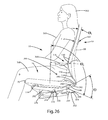
- FIG. 66 is a rear side elevational view of the arm assembly
- FIG. 67 is a top plan view of the arm assembly.
- FIG. 68 is a bottom plan view of the arm assembly.
- the terms “upper,” “lower,” “right,” “left,” “rear,” “front,” “vertical,” “horizontal,” and derivatives thereof shall relate to the invention as oriented in FIG. 1 .
- the invention may assume various alternative orientations and step sequences, except where expressly specified to the contrary.
- the specific devices and processes illustrated in the attached drawings, and described in the following specification are exemplary embodiments of the inventive concepts defined in the appended claims. Hence, specific dimensions and other physical characteristics relating to the embodiments disclosed herein are not to be considered as limiting, unless the claims expressly state otherwise.
- Various elements of the embodiments disclosed herein may be described as being operably coupled to one another, which includes elements either directly or indirectly coupled with one another.
- the term “chair” as utilized herein encompasses various seating arrangements, including office chairs, vehicle seating, home seating, stadium seating, theater seating, and the like.
- the reference numeral 10 ( FIGS. 1 and 2 ) generally designates a chair assembly embodying the present invention.
- the chair assembly 10 includes a castered base assembly 12 abutting a supporting floor surface 13 , a control or support assembly 14 supported by the castered base assembly 12 , a seat assembly 16 and back assembly 18 each operably coupled with the control assembly 14 , and a pair of arm assemblies 20 .
- the control assembly 14 ( FIG. 3 ) is operably coupled to the base assembly 12 such that the seat assembly 16 , the back assembly 18 and the arm assemblies 20 may be vertically adjusted between a fully lowered position A and a fully raised position B, and pivoted about a vertical axis 21 in a direction 22 .
- the seat assembly 16 is operably coupled to the control assembly 14 such that the seat assembly 16 is longitudinally adjustable with respect to the control assembly 14 between a fully retracted position C and a fully extended position D.
- the seat assembly 16 ( FIG. 4 ) and the back assembly 18 are operably coupled with the control assembly 14 and with one another such that the back assembly 18 is movable between a fully upright position E and a fully reclined position F, and further such that the seat assembly 16 is movable between a fully upright position G and a fully reclined position H corresponding to the fully upright position E and the fully reclined position F of the back assembly 18 , respectively.
- the base assembly 12 includes a plurality of pedestal arms 24 radially extending and spaced about a hollow central column 26 that receives a pneumatic cylinder 28 therein. Each pedestal arm 24 is supported above the floor surface 13 by an associated caster assembly 30 . Although the base assembly 12 is illustrated as including a multiple-arm pedestal assembly, it is noted that other suitable supporting structures maybe utilized, including but not limited to fixed columns, multiple leg arrangements, vehicle seat support assemblies, and the like.
- the seat assembly 16 ( FIG. 5 ) includes a relatively rigid seat support plate 32 having a forward edge 34 , a rearward edge 36 , and a pair of C-shaped guide rails 38 defining the side edges of the seat support plate 32 and extending between the forward edge 34 and the rearward edge 36 .
- the seat assembly 16 further includes a flexibly resilient outer seat shell 40 having a pair of upwardly turned side portions 42 and an upwardly turned rear portion 44 that cooperate to form an upwardly disposed generally concave shape.
- the seat shell 40 is comprised of a relatively flexible material such as a thermoplastic elastomer (TPE).
- the outer seat shell 40 is secured and sandwiched between the seat support plate 32 and a plastic, flexibly resilient seat pan 46 which is secured to the seat support plate 32 by a plurality of mechanical fasteners.
- the seat pan 46 includes a forward edge 48 , a rearward edge 50 , side edges 52 extending between the forward edge 48 and the rearward edge 50 , a top surface 54 and a bottom surface 56 that cooperate to form an upwardly disposed generally concave shape.
- the seat pan 46 includes a plurality of longitudinally extending slots 58 extending forwardly from the rearward edge 50 .
- the slots 58 cooperate to define a plurality of fingers 60 therebetween, each finger 60 being individually flexibly resilient.
- the seat pan 46 further includes a plurality of laterally oriented, elongated apertures 62 located proximate the forward edge 48 .
- the apertures 62 cooperate to increase the overall flexibility of the seat pan 46 in the area thereof, and specifically allow a forward portion 64 of the seat pan 46 to flex in a vertical direction 66 with respect to a rearward portion 68 of the seat pan 46 , as discussed further below.
- the seat assembly 16 further includes a foam cushion member 70 that rests upon the top surface 54 of the seat pan 46 and is cradled within the outer seat shell 40 , a fabric seat cover 72 ( FIGS. 1 and 2 ), and an upper surface 76 of the cushion member 70 .
- a spring support assembly 78 ( FIGS.
- the spring support assembly 78 includes a support housing 80 comprising a foam and having side portions 82 defining an upwardly concave arcuate shape.
- the spring support assembly 78 further includes a relatively rigid attachment member 84 that extends laterally between the side portions 82 of the support housing 80 and is located between the support housing 80 and the forward portion 64 of the seat pan 46 .
- a plurality of mechanical fasteners 86 secure the support housing 80 and the attachment member 84 to the forward portion 64 of the seat pan 46 .
- the spring support assembly 78 further includes a pair of cantilever springs 88 each having a distal end 90 received through a corresponding aperture 92 of the attachment member 84 , and a proximate end 94 secured to the seat support plate 32 such that the distal end 90 of each cantilever spring 88 may flex in the vertical direction 66 .
- a pair of linear bearings 96 are fixedly attached to the attachment member 84 and aligned with the apertures 92 thereof, such that the linear bearing 96 slidably receives the distal ends 90 of a corresponding cantilever spring 88 .
- the cantilever springs 88 cooperate to allow the forward portion 64 of the seat pan 46 , and more generally the entire forward portion of seat assembly 16 to flex in the vertical direction 66 when a seated user rotates forward on the seat assembly 16 and exerts a downward force on the forward edge thereof.
- the back assembly 18 ( FIGS. 7-9B ) includes a back frame assembly 98 and a back support assembly 99 supported thereby.
- the back frame assembly 98 is generally comprised of a substantially rigid material such as metal, and includes a laterally extending top frame portion 100 , a laterally extending bottom frame portion 102 , and a pair of curved side frame portion 104 extending between the top frame portion 100 and the bottom frame portion 102 and cooperating therewith to define an opening 106 having a relatively large upper dimension 108 and a relatively narrow lower dimension 110 .
- the back assembly 18 further includes a flexibly resilient, plastic back shell 112 having an upper portion 114 , a lower portion 116 , a pair of side edges 118 extending between the upper portion 114 and a lower portion 116 , a forwardly-facing surface 120 and a rearwardly-facing surface 122 , wherein the width of the upper portion 114 is generally greater than the width of the lower portion 116 , and the lower portion 116 is downwardly tapered to generally follow the rear elevational configuration of the frame assembly 98 .
- a lower reinforcement member 115 attaches to hooks 117 ( FIG. 9A ) of lower portion 116 of back shell 112 .
- Reinforcement member 115 includes a plurality of protrusions 113 that engage reinforcement ribs 134 to prevent side-to-side movement of lower reinforcement member 115 relative to back shell 112 . As discussed below, reinforcement member 115 pivotably interconnects back control link 342 ( FIG. 26 ) to lower portion 116 of back shell 112 at pivot points or axis 346 .
- the back shell 112 also includes a plurality of integrally molded, forwardly and upwardly extending hooks 124 ( FIG. 10 ) spaced about the periphery of the upper portion 114 thereof.
- An intermediate or lumbar portion 126 is located vertically between the upper portion 114 and the lower portion 116 of the back shell 112 , and includes a plurality of laterally extending slots 128 that cooperate to form a plurality of laterally extending ribs 130 located therebetween.
- the slots 128 cooperate to provide additional flexure to the back shell 112 in the location thereof. Pairings of lateral ribs 130 are coupled by vertically extending ribs 132 integrally formed therewith and located at an approximate lateral midpoint thereof.
- the vertical ribs 132 function to tie the lateral ribs 130 together and reduce vertical spreading therebetween as the back shell 112 is flexed at the intermediate portion 126 thereof when the back assembly 18 is moved from the upright position E to the reclined position F, as described further below.
- the back shell 112 further includes a plurality of laterally-spaced reinforcement ribs 134 extending longitudinally along the vertical length of the back shell 112 between the lower portion 116 and the intermediate portion 126 . It is noted that the depth of each of the ribs 134 increases the further along each of the ribs 134 from the intermediate portion 126 , such that the overall rigidity of the back shell 112 increases along the length of the ribs from the intermediate portion 126 toward the lower portion 116 .
- the back shell 112 further includes a pair of rearwardly-extending, integrally molded pivot bosses 138 forming part an upper back pivot assembly 140 .
- the back pivot assembly 140 ( FIGS. 11-13B ) includes the pivot bosses 138 of the back shell 112 , a pair of shroud members 142 that encompass respective pivot bosses 138 , a race member 144 , and a mechanical fastening assembly 146 .
- Each pivot boss 138 includes a pair of side walls 148 and a rearwardly-facing concave seating surface 150 having a vertically elongated pivot slot 152 extending therethrough.
- Each shroud member 142 is shaped so as to closely house the corresponding pivot boss 138 , and includes a plurality of side walls 154 corresponding to side walls 148 , and a rearwardly-facing concave bearing surface 156 that includes a vertically elongated pivot slot 143 extending therethrough, and which is adapted to align with the slot 152 of a corresponding pivot boss 138 .
- the race member 144 includes a center portion 158 extending laterally along and abutting the top frame portion 100 of the back frame assembly 98 , and a pair of arcuately-shaped bearing surfaces 160 located at the ends thereof.
- the center portion 158 includes a first portion 162 , and a second portion 164 , wherein the first portion 162 abuts a front surface of the top frame portion 100 and second portion 164 abuts a top surface of the top frame portion 100 .
- Each bearing surface 160 includes an aperture 166 extending therethrough and which aligns with a corresponding boss member 168 integral with the back frame assembly 98 .
- the shroud members 142 are positioned about the corresponding pivot bosses 138 of the back shell 112 and operably positioned between the back shell 112 and race member 144 such that the bearing surface 156 is sandwiched between the seating surface 150 of a corresponding pivot boss 138 and a bearing surface 160 .
- the mechanical fastening assemblies 146 each include a bolt 172 that secures a rounded abutment surface 174 of the bearing washer 176 in sliding engagement with an inner surface 178 of the corresponding pivot boss 138 , and threadably engages the corresponding boss member 168 of the back shell 112 .
- the upper back pivot assembly 140 allows the back support assembly 99 to pivot with respect to the back frame assembly in a direction 180 ( FIG. 8 ) about a pivot axis 182 ( FIG. 7 ).
- the back support assembly 99 ( FIGS. 9A and 9B ) further includes a flexibly resilient comfort member 184 ( FIGS. 15A and 15B ) attached to the back shell 112 and slidably supporting a lumbar assembly 186 .
- the comfort member 184 includes an upper portion 188 , a lower portion 190 , a pair of side portions 192 , a forward surface 193 and a rearward surface 195 , wherein the upper portion 188 , the lower portion 190 and the side portions 192 cooperate to form an aperture 194 that receives the lumbar assembly 186 therein. As best illustrated in FIGS.
- the comfort member 184 includes a plurality of box-shaped couplers 196 spaced about the periphery of the upper portion 188 and extending rearwardly from the rearward surface 195 .
- Each box-shaped coupler 196 includes a pair of side walls 198 and a top wall 200 that cooperate to form an interior space 202 .
- a bar 204 extends between the side walls 198 and is spaced from the rearward surface 195 .
- the comfort member 184 ( FIGS. 12-14 ) is secured to the back shell 112 by aligning and vertically inserting the hooks 124 of the back shell 112 into the interior space 202 of each of the box-shaped couplers 196 until the hooks 124 engage a corresponding bar 204 .
- forward surface 120 of the back shell 112 and the rearward surface 195 of the comfort member 184 are free from holes or apertures proximate the hooks 124 and box-shaped couplers 196 , thereby providing a smooth forward surface 193 and increasing the comfort to a seated user.
- the comfort member 184 ( FIGS. 15A and 15B ) includes an integrally molded, longitudinally extending sleeve 206 extending rearwardly from the rearward surface 195 and having a rectangularly-shaped cross-sectional configuration.
- the lumbar assembly 186 includes a forwardly laterally concave and forwardly vertically convex, flexibly resilient body portion 208 , and an integral support portion 210 extending upwardly from the body portion 208 .
- the body portion 208 is shaped such that the body portion vertically tapers along the height thereof so as to generally follow the contours and shape of the aperture 194 of the comfort member 184 .
- the support portion 210 is slidably received within the sleeve 206 of the comfort member 184 such that the lumbar assembly 186 is vertically adjustable with respect to the remainder of the back support assembly 99 between a fully lowered position I and a fully raised position J.
- a pawl member 212 selectively engages a plurality of apertures 214 spaced along the length of support portion 210 , thereby releasably securing the lumbar assembly 186 at selected vertical positions between the fully lowered position I and the fully raised position J.
- the pawl member 212 ( FIGS. 16 a and 16 b ) includes a housing portion 216 having engagement tabs 218 located at the ends thereof and rearwardly offset from an outer surface 220 of the housing portion 216 .
- a flexibly resilient finger 222 is centrally disposed within the housing portion 216 and includes a rearwardly-extending pawl 224 .
- the pawl member 212 ( FIG. 17 ) is positioned within an aperture 226 located within the upper portion 188 of the comfort member 184 such that the outer surface 220 of the housing portion 216 of the pawl member 212 is coplanar with the forward surface 193 of the comfort member 184 , and such that the engagement tabs 218 of the housing portion 216 abut the rearward surface 195 of the comfort member 184 .
- the support portion 210 of the lumbar assembly 186 is then positioned within the sleeve 206 of the comfort member 184 such that the sleeve 206 is slidable therein and the pawl 224 is selectively engageable with the apertures 214 , thereby allowing the user to optimize the position of the lumbar assembly 186 with respect to the overall back support assembly 99 .
- the body portion 208 of the lumbar assembly 186 includes a pair of outwardly extending integral handle portions 251 ( FIGS. 18A and 18B ) each having a C-shaped cross-sectional configuration defining a channel 253 therein that wraps about and guides along the respective side edge 192 of the comfort member 184 and the side edge 118 of the back shell 112 .
- a user adjusts the relative vertical position of the lumbar assembly 186 with respect to the back shell 112 by grasping one or both of the handle portions 251 and sliding the handle assembly 251 along the comfort member 184 and the back shell 112 in a vertical direction.
- a stop tab 228 is integrally formed within a distal end 230 and is offset therefrom so as to engage an end wall of the sleeve 206 of the comfort member 184 , thereby limiting the vertical downward travel of the support portion 210 of the lumbar assembly 186 with respect to the sleeve 206 of the comfort member 184 .
- the back assembly 99 ( FIGS. 9A and 9B ) also includes a cushion member 252 having an upper portion 254 and a lower portion 256 , wherein the lower portion 256 tapers along the vertical length thereof to correspond to the overall shape and taper of the back shell 112 and the comfort member 184 .
- the seat assembly 16 and the back assembly 18 are operably coupled to and controlled by the control assembly 14 ( FIG. 19 ) and a control input assembly 260 .
- the control assembly 14 ( FIGS. 20-22 ) includes a housing or base structure or ground structure 262 that includes a front wall 264 , a rear wall 266 , a pair of side walls 268 and a bottom wall 270 integrally formed with one another and that cooperate to form an upwardly opening interior space 272 .
- the bottom wall 270 includes an aperture 273 centrally disposed therein for receiving the cylinder assembly 28 ( FIG. 3 ) therethrough, as described below.
- the base structure 262 further defines an upper and forward pivot point 274 , a lower and forward pivot point 276 , and an upper and rearward pivot point 278 , wherein the control assembly 14 further includes a seat support structure 282 that supports the seat assembly 16 .
- the seat support structure 282 has a generally U-shaped plan form configuration that includes a pair of forwardly-extending arm portions 284 each including a forwardly located pivot aperture 286 pivotably secured to the base structure 262 by a pivot shaft 288 for pivoting movement about the upper and forward pivot point 274 .
- the seat support structure 282 further includes a rear portion 290 extending laterally between the arm portions 284 and cooperating therewith to form an interior space 292 within which the base structure 262 is received.
- the rear portion 290 includes a pair of rearwardly-extending arm mounting portions 294 to which the arm assemblies 20 are attached as described below.
- the seat support structure 282 further includes a control input assembly mounting portion 296 to which the control input assembly 260 is mounted.
- the seat support structure 282 further includes a pair of bushing assemblies 298 that cooperate to define a pivot point 300 .
- the control assembly 14 further includes a back support structure 302 having a generally U-shaped plan view configuration and including a pair of forwardly-extending arm portions 304 each including a pivot aperture 305 and pivotably coupled to the base structure 262 by a pivot shaft 307 such that the back support structure 302 pivots about the lower and forward pivot point 276 .
- the back support structure 302 includes a rear portion 308 that cooperates with the arm portions 304 to define an interior space 310 which receives the base structure 262 therein.
- the back support structure 302 further includes a pair of pivot apertures 312 located along the length thereof and cooperating to define a pivot point 314 . It is noted that in certain instances, at least a portion of the back frame assembly 98 may be included as part of the back support structure 302 .
- the control assembly 14 further includes a plurality of control links 316 each having a first end 318 pivotably coupled to the seat support structure 282 by a pair of pivot pins 321 for pivoting about the pivot point 300 , and a second end 322 pivotably coupled to corresponding pivot apertures 312 of the back support structure 302 by a pair of pivot pins 324 for pivoting about the pivot point 314 .
- the control links 316 control the motion, and specifically the recline rate of the seat support structure 282 with respect to the back support structure 302 as the chair assembly is moved to the recline position, as described below.
- a bottom frame portion 102 of the back frame assembly 98 is configured to connect to the back support structure 302 via a quick connect arrangement 326 .
- Each arm portion 304 of the back support structure 302 includes a mounting aperture 328 located at a proximate end 330 thereof.
- the quick connect arrangement 326 includes a configuration of the bottom frame portion 102 of the back frame assembly 98 to include a pair of forwardly-extending coupler portions 332 that cooperate to define a channel 334 therebetween that receives the rear portion 308 and the proximate ends 330 of the arm portions 304 therein.
- Each coupler portion 332 includes a downwardly extending boss 336 that aligns with and is received within a corresponding aperture 328 .
- Mechanical fasteners, such as screws 338 are then threaded into the bosses 336 , thereby allowing a quick connection of the back frame assembly 98 to the control assembly 14 .
- the base structure 262 , the seat support structure 282 , the back support structure 302 and the control links 316 cooperate to form a four-bar linkage assembly that supports the seat assembly 16 , the back assembly 18 , and the arm assemblies 20 .
- FIG. 24 illustrates the component of the chair assembly 10 shown in a reclined position in dashed lines, wherein the reference numerals of the chair in the reclined position are designated with a “′”.
- the four-bar linkage assembly of the control assembly 14 cooperates to recline the seat assembly 16 from the upright position G to the reclined position H as the back assembly 184 is moved from the upright position E to the reclined position F, wherein the upper and lower representations of the positions E and F in FIG. 24 illustrate that the upper and lower portions of the back assembly 18 reclines as a single piece.
- the control link 316 is configured and coupled to the seat support structure 282 and the back support structure 302 to cause the seat support structure 282 to rotate about the first pivot point 274 as the back support structure 302 is pivoted about the second pivot point 276 .
- the seat support structure 302 is rotated about the first pivot point 274 at between about 1 ⁇ 3 and about 2 ⁇ 3 the rate of rotation of the back support structure 302 about the second pivot point 276 , more preferably the seat support structure rotates about the first pivot point 274 at about half the rate of rotation of the back support structure 302 about the second pivot point 276 , and most preferably the seat assembly 16 reclines to an angle ⁇ of about 9° from the fully upright position G to the fully reclined position H, while the back assembly 18 reclines to an angle ⁇ of about 18° from the fully upright position E to the fully reclined position F.
- the first pivot point 274 is located above and forward of the second pivot point 276 when the chair assembly 10 is at the fully upright position, and when the chair assembly 10 is at the fully reclined position as the base structure 262 remains fixed with respect to the supporting floor surface 13 as the chair assembly 10 is reclined.
- the third pivot point 300 remains behind and below the relative vertical height of the first pivot point 274 throughout the reclining movement of the chair assembly 10 . It is further noted that the distance between the first pivot point 274 and the second pivot point 276 is greater than the distance between the third pivot point 300 and the fourth pivot point 314 throughout the reclining movement of the chair assembly 10 . As best illustrated in FIG.
- a longitudinally extending center line axis 340 of the control link 316 forms an acute angle ⁇ with the seat support structure 282 when the chair assembly 10 is in the fully upright position and an acute angle ⁇ ′ when the chair assembly 10 is in the fully reclined position. It is noted that the center line axis 340 of the control link 316 does not rotate past an orthogonal alignment with the seat support structure 282 as the chair assembly 10 is moved between the fully upright and fully reclined positions thereof.
- a back control link 342 includes a forward end that is pivotably connected to the seat support structure 282 at a fifth pivot point 344 .
- a rearward end 345 of the back control link 342 is connected to the lower portion 116 of the back shell 112 at a sixth pivot point 346 .
- the sixth pivot point 346 is optional, and the back control link 342 and the back shell 112 may be rigidly fixed to one another.
- the pivot point 346 may include a stop feature that limits rotation of the back control link 342 relative to the back shell 112 in a first and/or second rotational direction.
- the pivot 346 may include a stop feature that permits clockwise rotation of the lower portion 116 of the back shell 112 relative to the control link 342 . This permits the lumbar to become flatter if a rearward/horizontal force tending to reduce dimension D1 is applied to the lumbar portion of the back shell 112 .
- the stop feature may be configured to prevent rotation of the lower portion 116 of the back shell 112 in a counter clockwise direction ( FIG. 26 ) relative to the control link 342 . This causes the link 342 and the lower portion 116 of the back shell 112 to rotate at the same angular rate as the back assembly 18 when a user reclines in the chair by pushing against an upper portion of the back assembly 18 .
- a cam link 350 is also pivotably connected to the seat support structure 282 for rotation about the pivot point or axis 344 .
- the cam link 350 has a curved lower cam surface 352 that slidably engages an upwardly facing cam surface 354 formed in the back support structure 302 .
- a pair of torsion springs 356 (see also FIGS. 18A and 18B ) rotatably bias the back control link 342 and the cam link 350 in a manner that tends to increase the angle ⁇ ( FIG. 26 ).
- the torsion springs 356 generate a force tending to rotate the control link 342 in a counter-clockwise direction ( FIG. 26 ), and simultaneously rotate the cam link 350 in a clockwise direction ( FIG. 26 ).
- the torsion springs 356 tend to increase the angle ⁇ between back the control link 342 and the cam link 350 .
- a stop 348 on the seat support structure 282 limits counter clockwise rotation of the back control link 342 to the position shown in FIG. 26 . This force may also bias the control link 342 in a counter clockwise direction into the stop feature.
- the back shell 112 is flexible, particularly in comparison to the rigid back frame structure 98 .
- the back frame structure 98 is rigidly connected to the back support structure 302 , and therefore pivots with the back support structure 302 .
- the forces generated by the torsion springs 356 push upwardly against the lower portion 116 of the back shell 112 .
- the slots 128 in the back shell structure 112 create additional flexibility at the lumbar support portion 126 of the back shell 112 .
- the force generated by the torsion springs 356 also tends to cause the lumbar portion 126 of the back shell 112 to bend forwardly such that the lumbar portion 126 has a higher curvature than the regions adjacent the lumbar portion 126 .
- the position of the lumbar assembly 186 is vertically adjustable. Vertical adjustment of the lumbar assembly 186 also adjusts the way in which the back shell 112 flexes/curves during recline of the chair back. In FIG. 26 , the lumbar assembly 186 is adjusted to an intermediate or neutral position, such that the curvature of the lumbar portion 126 of the back shell 112 is also intermediate or neutral. With further reference to FIG. 27 , if the vertical position of the lumbar assembly 186 is adjusted, the angle ⁇ is reduced, and the curvature of the lumbar region 126 is reduced. As shown in FIG. 27 , this also causes angle ⁇ 1 to become greater, and the overall shape of the back shell 112 to become relatively flat.
- the four-bar linkage defined by the links and the structures 262 , 282 , 302 , 316 , and the pivot points 274 , 276 , 300 , 314 will shift (as described above) from the configuration of FIG. 26 to the configuration of FIG. 28 .
- This causes an increase in the distance between the pivot point 344 and the cam surface 354 .
- This causes an increase in the angle ⁇ from about 49.5° ( FIG. 26 ) to about 59.9° ( FIG. 28 ).
- the back control link 342 , the cam link 350 , and the torsion springs 356 provide for greater curvature of the lumbar region 116 to reduce the curvature of a user's back as the user leans back in the chair.
- the distance D between the lumbar region 126 and the seat 16 increases from 174 mm to 234 mm.
- a dimension D1 between the lumbar region 126 of the back shell 112 and the back frame structure 98 also increases as the back tilts from the position of FIG. 26 to the position of FIG. 28 .
- the increase in the dimension D1 reduces the increase in dimension D because the lumbar region 126 of the back shell 112 is shifted forward relative to the back frame 98 during recline.
- a spine 360 of a seated user 362 tends to curve forwardly in the lumbar region 364 by a first amount when a user is seated in an upright position.
- the curvature of the lumbar region 364 tends to increase, and the user's spine 360 will also rotate somewhat about hip joint 366 relative to a user's femur 368 .
- FIG. 27 shows the back assembly 18 of the chair assembly 10 in an upright position with the lumbar region 126 of the back shell 112 adjusted to a flat position.
- the back control link 342 and the cam link 350 both rotate in a clockwise direction.
- the cam link 350 rotates at a somewhat higher rate, and the angle ⁇ therefore changes from 31.4° to 35.9°.
- the distance D changes from 202 mm to 265 mm, and the angle ⁇ 1 changes from 24.2° to 24.1°.
- the angle ⁇ is 93.6°, and the distance D is 202 mm.
- the back shell 112 curves as the seat back is tilted rearwardly.
- the increase in curvature in the lumbar region 126 from the upright to the reclined position is significantly greater if the curvature is initially adjusted to a higher level. This accounts for the fact that the curvature of a user's back does not increase as much when a user reclines if the user's back is initially in a relatively flat condition when seated upright. Restated, if a user's back is relatively straight when in an upright position, the user's back will remain relatively flat even when reclined, even though the degree of curvature will increase somewhat from the upright position to the reclined position.
- each spring assembly 442 bias the back assembly 18 from the reclined position F towards the upright position E.
- each spring assembly 442 includes a cylindrically-shaped housing 444 having a first end 446 and a second end 448 .
- Each spring assembly 442 further includes a compression coil spring 450 , a first coupler 452 and a second coupler 454 .
- the first coupler is secured to the first end 446 of the housing 444
- the second coupler 454 is secured to a rod member 456 that extends through the coil spring 450 .
- a washer 457 is secured to a distal end of the rod member 458 and abuts an end of the coil spring 450 , while the opposite end of the coil spring 450 abuts the second end 448 of the housing 444 .
- the first coupler 452 is pivotably secured to the back support structure 302 by a pivot pin 460 for pivoting movement about a pivot point 461 , wherein the pivot pin 460 is received within pivot apertures 462 of the back support structure 302 , while the second coupler 454 is pivotably coupled to a moment arm shift assembly 466 ( FIGS. 30-32 ) by a shaft 464 for pivoting about a pivot point 465 .
- the moment arm shift assembly is adapted to move the biasing or spring assembly 442 from a low tension setting ( FIG. 33A ) to a high tension setting ( FIG. 34A ) wherein the force exerted by the biasing assembly 442 on the back assembly 18 is increased relative to the low-tension setting.
- the moment arm shift assembly 466 includes an adjustment assembly 468 , a moment arm shift linkage assembly 470 operably coupling the control input assembly 260 to the adjustment assembly 468 and allowing the operator to move the biasing assembly 442 between the low and high tension settings, and an adjustment assist assembly 472 that is adapted to reduce the amount of input force required to be exerted by the user on the control input assembly 260 to move the moment arm shift assembly 466 from the low tension setting to the high tension setting, as described below.
- the adjustment assembly 468 comprises a pivot pin 467 that includes a threaded aperture that threadably receives a threaded adjustment shaft 476 therein.
- the adjustment shaft 476 includes a first end 478 and a second end 484 , wherein the first end 478 extends through an aperture 480 of the base structure 262 and is guided for pivotal rotation about a longitudinal axis by a bearing assembly 482 .
- the pivot pin 467 is supported from the base structure 262 by a linkage assembly 469 that includes a pair of linkage arms 471 each having a first end 473 pivotably coupled to the second coupler 454 by the pivot pin 464 and a second end 475 pivotably coupled to the base structure 262 by a pivot pin 477 pivotably received within a pivot aperture 479 of the base structure 262 for pivoting about a pivot point 481 , and an aperture 483 that receives a respective end of the pivot pin 467 .
- the pivot pin 467 is pivotably coupled with the linkage arms 471 along the length thereof.
- the moment arm shift linkage assembly 470 ( FIGS. 30A and 30B ) includes a first drive shaft 486 extending between the control input assembly 260 and a first beveled gear assembly 488 , and a second drive shaft 490 extending between and operably coupling the first beveled gear assembly 488 with a second beveled gear assembly 492 , wherein the second beveled gear assembly 492 is connected to the adjustment shaft 476 .
- the first drive shaft 486 includes a first end 496 operably coupled to the control input assembly 260 by a first universal joint assembly 498 , while the second end 500 of the first drive shaft 486 is operably coupled to the first beveled gear assembly 488 by a second universal joint assembly 502 .
- the first end 496 of the first drive shaft 486 includes a female coupler portion 504 of the first universal joint assembly 498
- the second end 500 of the first drive shaft 486 includes a female coupler portion 506 of the second universal joint assembly 502
- the first beveled gear assembly 488 includes a housing assembly 508 that houses a first beveled gear 510 and a second beveled gear 512 therein.
- the first beveled gear 510 includes an integral male coupler portion 514 of the second universal joint 502 .
- the first end 496 of the second drive shaft 490 is coupled to the first beveled gear assembly 488 by a third universal joint assembly 516 .
- a first end 518 of the second drive shaft 490 includes a female coupler portion 520 of the third universal joint assembly 516 .
- the second beveled gear 512 includes an integral male coupler portion 522 of the third universal joint assembly 516 .
- a second end 524 of the second drive shaft 490 includes a plurality of longitudinally extending splines 526 that mate with corresponding longitudinally extending splines (not shown) of a coupler member 528 .
- the coupler member 528 couples the second end 524 of the second drive shaft 490 with the second beveled gear assembly 492 via a fourth universal joint assembly 530 .
- the fourth universal joint assembly 530 includes a housing assembly 532 that houses a first beveled gear 534 coupled to the coupler member 528 via the fourth universal joint assembly 530 , and a second beveled gear 536 fixed to the second end 484 of the adjustment shaft 476 .
- the coupler member 428 includes a female coupler portion that receives a male coupler portion 540 integral with the first beveled gear 534 .
- the adjustment assembly 468 of the moment arm shift assembly 466 is operably supported by the base structure 262
- the control input assembly 260 is operably supported by the control input assembly mounting portion 296 of the seat support structure 282 .
- the relative angles and distances between the control input assembly 260 and the adjustment assembly 468 of the moment arm shift assembly 466 change as the seat support structure 282 is moved between the fully upright position G and the fully reclined H.
- the third and fourth universal joint assemblies 516 , 530 , and the spline assembly between the splines cooperate to compensate for these relative changes in angle and distance.
- the moment arm shift assembly 466 functions to adjust the biasing assemblies 442 between the low-tension and high-tension settings.
- the biasing assemblies 442 are shown in a low-tension setting with the chair assembly 10 in an upright position in FIG. 33A , and the low-tension setting with the chair assembly 10 in a reclined position in FIG. 33B
- FIG. 34A illustrates the biasing assemblies 442 in the high-tension setting with the chair in an upright position
- FIG. 34B the biasing assemblies is in the high-tension setting with the chair assembly 10 in the reclined position.
- the distance 542 serves as a reference to the amount of compression exerted on the spring assembly 442 when the moment arm shift assembly 466 is positioned in the low-tension setting and the chair is in the upright position.
- the distance 542 ( FIG. 33B ) comparatively illustrates the increased amount of compressive force exerted on the spring assembly 442 when the moment arm shift assembly 466 is in the high-tension setting and the chair is in the upright position. The user adjusts the amount of force exerted by the biasing assemblies 442 on the back support structure 302 by moving the moment arm shift assembly 466 from the low-tension setting to the high-tension setting.
- the operator through an input to the control input assembly 260 , drives the adjustment shaft 476 of the adjustment assembly 468 in rotation via the moment arm shift linkage assembly 470 , thereby causing the pivot shaft 467 to travel along the length of the adjustment shaft 476 , thus changing the compressive force exerted on the spring assemblies 442 as the pivot shaft 467 is adjusted with respect to the base structure 262 .
- the pivot shaft 467 travels within a slot 544 located within a side plate member 546 attached to a side wall 268 of the base structure 262 .
- the distance 542 when the moment arm shift assembly 466 is in the high-tension setting and the chair assembly 10 is in the upright position is greater than the distance 542 when the moment arm shift 466 is in the low-tension setting and the chair is in the upright position, thereby indicating that the compressive force as exerted on the spring assemblies 442 , is greater when the moment arm shift is in the high-tension setting as compared to a low-tension setting.
- the distance 543 FIG. 33B
- the distance 543 FIG. 34B
- the change in the biasing force exerted by the biasing assemblies 442 corresponds to a change in the biasing torque exerted about the second pivot point 276 , and that in certain configurations, a change in the biasing torque is possible without a change in the length of the biasing assemblies 442 or a change in the biasing force.
- FIG. 35 is a graph of the amount of torque exerted about the second pivot point 276 forcing the back support structure 302 from the reclined position towards the upright position as the back support structure 302 is moved between the reclined and upright positions.
- the biasing assemblies 442 exert a torque about the second pivot point 276 of about 652 inch-pounds when the back support structure is in the upright position and the moment arm shift 466 is in the low tension setting, and of about 933 inch-pounds when the back support structure is in the reclined position and the moment arm shift 466 is in the low tension setting, resulting in a change of approximately 43%.
- the biasing assemblies 442 exert a torque about the second pivot point 274 of about 1.47E+03 inch-pounds when the back support structure is in the upright position and the moment arm shift 466 is in the high tension setting, and of about 2.58E+03 inch-pounds when the back support structure is in the reclined position and the moment arm shift 466 is in the high tension setting, resulting in a change of approximately 75%.
- This significant change in the amount of torque exerted by the biasing assembly 442 between the low tension setting and the high tension setting of the moment arm shift 466 as the back support structure 302 is moved between the upright and reclined positions allows the overall chair assembly 10 to provide proper forward back support to users of varying height and weight.
- the adjustment assist assembly 472 assists an operator in moving the moment arm shift assembly 466 from the high-tension setting to the low-tension setting.
- the adjustment assist assembly 472 includes a coil spring 548 secured to the front wall 264 of the base structure 262 by a mounting structure 550 , and a catch member 552 that extends about the shaft 306 fixed with the linkage arms 471 , and that includes a catch portion 556 defining an aperture 558 that catches a free end 560 of the coil spring 548 .
- the coil spring 548 exerts a force F on the catch member 552 and shaft 306 and the linkage arms 471 in an upward vertical direction, thereby reducing the amount of input force the user must exert on the control input assembly 260 to move the moment arm shift assembly 466 from the low-tension setting to the high-tension setting.
- a direct drive assembly 562 includes a drive assembly 564 and a linkage assembly 566 that couples the control input assembly 260 with the drive assembly 564 , thereby allowing a user to adjust the linear position of the seat by adjusting the linear position of the seat assembly 16 with respect to the control assembly 14 .
- the seat support plate 32 includes the C-shaped guiderails 38 which wrap about and slidably engage corresponding guide flanges 570 of a control plate 572 of the control assembly 14 .
- connection rails 574 are positioned within the corresponding guiderails 38 and are coupled with the seat support plate 32 .
- a pair of C-shaped bushing members 576 extend longitudinally within the connection rails 574 and are positioned between the connection rails 574 and the guide flanges 570 .
- the drive assembly 564 includes a rack member 578 having a plurality of downwardly extending teeth 580 .
- the drive assembly 564 further includes a rack guide 582 having a C-shaped cross-sectional configuration defining a channel 584 that slidably receives the rack member 578 therein.
- the rack guide 582 includes a relief 586 located along the length thereof that matingly receives a bearing member 588 therein.
- the bearing member 588 may be formed as an integral portion of the rack guide 582 .
- the drive assembly 564 further includes a drive shaft 590 having a first end universally coupled with the control input assembly 260 and the second end 594 having a plurality of radially-spaced teeth 596 .
- the seat support plate 32 is slidably coupled with the control plate 572 as described above, with the rack member 578 being secured to an underside of the seat support plate 32 and the rack guide 582 being secured within an upwardly opening channel 598 of the control plate 572 .
- an input force exerted by the user to the control input assembly 260 is transferred to the drive assembly 564 via the linkage assembly 566 , thereby driving the teeth 596 of the drive shaft 590 against the teeth 580 of the rack member 578 and causing the rack member 578 and the seat support plate 32 to slide with respect to the rack guide 582 and the control plate 572 .
- the chair assembly 10 includes a height adjustment assembly 600 that permits vertical adjustment of seat 16 and back 18 relative to the base assembly 12 .
- Height adjustment assembly 600 includes a pneumatic cylinder 28 that is vertically disposed in central column 26 of base assembly 12 in a known manner.
- a bracket structure 602 is secured to housing or base structure 262 , and upper end portion 604 of pneumatic cylinder 28 is received in opening 606 of base structure 262 in a known manner.
- Pneumatic cylinder 28 includes an adjustment valve 608 that can be shifted down to release pneumatic cylinder 28 to provide for height adjustment.
- a bell crank 610 has an upwardly extending arm 630 and a horizontally extending arm 640 that is configured to engage a release valve 608 of pneumatic cylinder 28 .
- Bell crank 610 is rotatably mounted to bracket 602 .
- a cable assembly 612 operably interconnects bell crank 610 with adjustment wheel/lever 620 .
- Cable assembly 612 includes an inner cable 614 and an outer cable or sheath 616 .
- Outer sheath 616 includes a spherical ball fitting 618 that is rotatably received in a spherical socket 622 formed in bracket 602 .
- a second ball fitting 624 is connected to end 626 of inner cable 614 .
- Second ball fitting 624 is rotatably received in a second spherical socket 628 of upwardly extending arm 630 of bell crank 610 to permit rotational movement of the cable end during height adjustment.
- a second or outer end portion 632 of inner cable 614 wraps around wheel 620 , and an end fitting 634 is connected to inner cable 614 .
- a tension spring 636 is connected to end fitting 634 and to the seat structure at point 638 .
- Spring 636 generates tension on inner cable 614 in the same direction that cable 614 is shifted to rotate bell crank 610 when valve 608 is being released.
- spring 636 does not generate enough force to actuate valve 608
- spring 636 does generate enough force to bias arm 640 of bell crank 610 into contact with valve 608 . In this way, lost motion or looseness that could otherwise exist due to tolerances in the components is eliminated.
- a user manually rotates adjustment wheel 620 , thereby generating tension on inner cable 614 .
- the control input assembly 260 ( FIGS. 19 and 41-43 ) comprises a first control input assembly 700 and a second control input assembly 702 each adapted to communicate inputs from the user to the chair components and features coupled thereto, and housed within a housing assembly 704 .
- the control input assembly 260 includes an anti-back drive assembly 706 , an overload clutch assembly 708 , and a knob 710 .
- the anti-back drive mechanism or assembly 706 that prevents the direct drive assembly 562 ( FIGS. 36 and 37 ) and the seat assembly 16 from being driven between the retracted and extended positions C, D without input from the control assembly 700 .
- the anti-back drive assembly 706 is received within an interior 712 of the housing assembly 704 and includes an adaptor 714 that includes a male portion 716 of a universal adaptor coupled to the second end 594 of the drive shaft 590 ( FIG. 37 ) at one end thereof, and including a spline connector 717 at the opposite end.
- a cam member 718 is coupled with the adaptor 714 via a clutch member 720 .
- the cam member 718 includes a spline end 722 coupled for rotation with the knob 710 , and a cam end 724 having an outer cam surface 726 .
- the clutch member 720 includes an inwardly disposed pair of splines 723 that slidably engage the spline connector 717 having a cam surface 730 that cammingly engages the outer cam surface 726 of the cam member 718 , as described below.
- the clutch member 720 has a conically-shaped clutch surface 719 that is engagingly received by a locking ring 732 that is locked for rotation with respect to the housing assembly 704 and includes a conically-shaped clutch surface 721 corresponding to the clutch surface 719 of the clutch member 720 , and cooperating therewith to form a cone clutch.
- a coil spring 734 biases the clutch member 720 towards engaging the locking ring 732 .
- the biasing spring 734 forces the conical surface of the clutch member 720 into engagement with the conical surface of the locking ring 732 , thereby preventing the “back drive” or adjustment of the seat assembly 16 between the retracted and extended positions C, D, simply by applying a rearward or forward force to the seat assembly 16 without input from the first control input assembly 700 .
- an operator moves the seat assembly 16 between the retracted and extended positions C, D by actuating the direct drive assembly 562 via the first control input assembly 700 .
- the rotational force exerted on the knob 710 by the user is transmitted from the knob 710 to the cam member 718 .
- the outer cam surface 726 of the cam member 718 acts on the cam surface 730 of the clutch member 720 , thereby overcoming the biasing force of the spring 734 and forcing the clutch member 720 from an engaged position, wherein the clutch member 720 disengages the locking ring 732 .
- the rotational force is then transmitted from the cam member 718 to the clutch member 720 and then to the adaptor 714 , which is coupled to the direct drive assembly 762 via the linkage assembly 566 .
- a rotational ring-shaped damper element 736 comprising a thermoplastic elastomer (TPE), is located within the interior 712 of the housing 704 , and is attached to the clutch member 720 . In the illustrated example, the damper element 736 is compressed against and frictionally engages the inner wall of the housing assembly 704 .
- TPE thermoplastic elastomer
- the first control input assembly 700 also includes a second knob 738 adapted to allow a user to adjust the vertical position of the chair assembly between the lowered position A and the raised position B, as described below.
- the second control input assembly 702 is adapted to adjust the tension exerted on the back assembly 18 during recline, and to control the amount of recline of the back assembly 18 .
- a first knob 740 is operably coupled to the moment arm shift assembly 466 by the moment arm shift linkage assembly 470 .
- the second control input assembly 702 includes a male universal coupling portion 742 that couples with the female universal coupler portion 504 ( FIGS. 30 and 31 ) of the shaft 486 of the moment arm shift linkage assembly 470 .
- a second knob 760 is adapted to adjust the amount of recline of the back assembly 18 via a cable assembly 762 operably coupling the second knob 760 to a variable back stop assembly 764 ( FIG. 43 ).
- the cable assembly 762 includes a first cable routing structure 766 , a second cable routing structure 768 and a cable tube 770 extending therebetween and slidably receiving an actuator cable 772 therein.
- the cable 772 includes a distal end 774 that is fixed with respect to the base structure 262 , and is biased in a direction 776 by a coil spring 778 .
- the variable back stop assembly 764 includes a stop member 780 having a plurality of vertically graduated steps 782 , a support bracket 784 fixedly supported with respect to the seat assembly 16 , and a slide member 786 slidably coupled to the support bracket 784 to slide in a fore-to-aft direction 788 and fixedly coupled to the stop member 780 via a pair of screws 790 .
- the cable 772 is clamped between the stop member 780 and the slide member 786 such that longitudinal movement of the cable 772 causes the stop member 780 to move in the fore-and-aft direction 788 .
- a user adjusts the amount of back recline possible by adjusting the location of the stop member 780 via an input to the second knob 760 .
- the amount of back recline available is limited by which select step 782 of the stop member 780 contacts a rear edge 792 of the base structure 262 as the back assembly 18 moves from the upright towards the reclined position.
- Each arm assembly 20 ( FIGS. 44-46 ) includes an arm support assembly 800 pivotably supported from an arm base structure 802 , and adjustably supporting an armrest assembly 804 .
- the arm support assembly 800 includes a first arm member 806 , a second arm 808 , an arm support structure 810 , and an armrest assembly support member 812 that cooperate to form a four-bar linkage assembly.
- the first arm member 806 has a U-shaped cross-sectional configuration and includes a first end 814 pivotably coupled to the arm support structure 810 for pivoting about a pivot point 816 , and a second end 818 pivotably coupled to the armrest assembly support member 812 for pivoting movement about a pivot point 820 .
- the second arm member 808 has a U-shaped cross-sectional configuration and includes a first end 822 pivotably coupled to the arm support structure 810 for pivoting about a pivot point 824 , and a second end 826 pivotably coupled to the armrest assembly support member 812 for pivoting about a pivot point 828 .
- the four-bar linkage assembly of the arm support assembly 800 allows the armrest assembly 804 to be adjusted between a fully raised position K and a fully lowered position L, wherein the distance between the fully raised position K and fully lowered position L is preferably at least about 4 inches.
- Each arm assembly further includes a first arm cover member 807 having a U-shaped cross-sectional configuration and including a first edge portion 809 , and a second arm cover member 811 having a U-shaped cross-sectional configuration and including a second edge portion 813 , wherein the first arm member 806 is housed within the first arm cover member 807 and the second arm member 808 is housed within the second arm cover member 811 , such that the second edge portion 813 overlaps with the first edge portion 809 .
- Each arm base structure 802 includes a first end 830 connected to the control assembly 14 , and a second end 832 pivotably supporting the arm support structure 810 for rotation of the arm assembly 20 about a vertical axis 835 in a direction 837 .
- the first end 830 of the arm base structure 802 includes a body portion 833 and a narrowed bayonet portion 834 extending outwardly therefrom.
- the body portion 833 and bayonet portion 834 of the first end 830 of the arm base structure 802 are received between the control plate 572 and the seat support structure 282 , and are fastened thereto by a plurality of mechanical fasteners (not shown) that extend through the body portion 833 and bayonet portion 834 of the arm-base structure 802 , the control plate 572 and the seat support structure 282 .
- the second end 832 of the arm base structure 802 pivotably receives the arm support structure 810 therein.
- the arm base structure 802 includes an upwardly opening bearing recess 836 having a cylindrically-shaped upper portion 838 and a conically-shaped lower portion 840 .
- a bushing member 842 is positioned within the bearing recess 836 and is similarly configured as the lower portion 840 of the bearing recess 836 , including a conically-shaped portion 846 .
- the arm support structure 810 includes a lower end having a cylindrically-shaped upper portion 848 and a conically-shaped lower portion 850 received within the lower portion 846 of the bushing member 842 .
- An upper end 852 of the arm support structure 810 is configured to operably engage within a vertical locking arrangement, as described below.
- a pin member 854 is positioned within a centrally located and axially extending bore 856 of the arm support structure 810 .
- the pin member 854 is formed from steel, while the upper end 852 of the arm support structure 810 comprises a powdered metal that is formed about a proximal end of the pin member 854 , and wherein the combination of the upper end 852 and the pin member 854 is encased within an outer aluminum coating.
- a distal end 853 of the pin member 854 includes an axially extending threaded bore 855 that threadably receives an adjustment screw 857 therein.
- the arm base structure 802 includes a cylindrically-shaped second recess 858 separated from the bearing recess 836 by a wall 860 .
- a coil spring 864 is positioned about the distal end 853 of the pin member 854 within the second recess 858 , and is trapped between the wall 860 of the arm base structure 802 and a washer member 866 , such that the coil spring 864 exerts a downward force in the direction of arrow 868 on the pin member 854 , thereby drawing the lower end of the arm support structure 810 into close frictional engagement with the bushing member 842 and drawing the bushing member 842 into close frictional engagement with the bearing recess 836 of the arm base structure 802 .
- the adjustment screw 857 may be adjusted so as to adjust the amount of frictional interference between the arm support structure 810 , the bushing member 842 and the arm base structure 802 and increasing the force required to be exerted by the user to move the arm assembly 20 about the pivot access 835 in pivot direction 837 .
- the pivot connection between the arm support structure 810 and the arm base structure 802 allows the overall arm assembly 800 to be pivoted inwardly in a direction 876 ( FIG. 48 ) from a line 874 extending through pivot access 835 and extending parallel with a center line axis 872 of the seat assembly 16 , and outwardly from the line 874 in a direction 878 .
- the arm assembly 20 pivots greater than or equal to about 17° in the direction 876 from the line 874 , and greater than or equal to about 22° in the direction 878 from the line 874 .
- a gear member 882 includes a plurality of teeth 884 that are arranged in an arc about pivot point 816 .
- a lock member 886 is pivotably mounted to arm 806 at pivot 888 , and includes a plurality of teeth 890 that selectively engage teeth 884 of gear member 882 .
- teeth 884 and 890 are engaged, the height of the arm rest 804 is fixed due to the rigid triangle formed between pivot points 816 , 824 and 888 . If a downward force F4 is applied to the armrest, a counter clockwise ( FIG. 50 ) moment is generated on lock member 886 . This moment pushes teeth 890 into engagement with teeth 884 , thereby securely locking the height of the armrest.
- An elongated lock member 892 is rotatably mounted to arm 806 at pivot 894 .
- a low friction polymer bearing member 896 is disposed over upper curved portion 893 of elongated lock member 892 .
- a manual release lever or member 898 includes a pad 900 that can be shifted upwardly by a user to selectively release teeth 890 of lock member 886 from teeth 884 of gear member 882 to permit vertical height adjustment of the armrest.
- a leaf spring 902 includes a first end 904 that engages a notch 906 formed in upper edge 908 of elongated locking member 892 .
- leaf spring 902 is cantilevered to locking member 892 at notch 906 .
- An upwardly-extending tab 912 of elongated locking member 892 is received in an elongated slot 910 of leaf spring 902 to thereby locate spring 902 relative to locking member 892 .
- the end 916 of leaf spring 902 bears upwardly (F1) on knob 918 of locking member 886 , thereby generating a moment tending to rotate locking member 886 in a clockwise (released) direction ( FIG. 51 ) about pivot 888 .
- Leaf spring 902 also generates a clockwise moment on elongated locking member 892 at notch 906 , and also generates a moment on locking member 886 tending to rotate locking member 886 about pivot 888 in a clockwise (released) direction. This moment tends to disengage gears 890 from gears 884 . If gears 890 are disengaged from gears 884 , the height of the arm rest assembly can be adjusted.
- Locking member 886 includes a recess or cut-out 920 ( FIG. 50 ) that receives pointed end 922 of elongated locking member 892 .
- Recess 920 includes a first shallow V-shaped portion having a vertex 924 .
- the recess also includes a small recess or notch 926 , and a transverse, upwardly facing surface 928 immediately adjacent notch 926 .
- the leaf spring 902 generates a moment acting on locking member 886 tending to disengage gears 890 from gears 884 .
- this engagement prevents rotational motion of locking member 886 in a clockwise (released) direction, thereby locking gears 890 and 884 into engagement with one another and preventing height adjustment of the armrest.
- a user pulls upwardly on pad 900 against a small leaf spring 899 ( FIG. 50 ).
- the release member 898 rotates about an axis 897 that extends in a fore-aft direction, and an inner end of manual release lever 898 pushes downwardly against bearing member 896 /upper curved portion 893 ( FIG. 51 ) of elongated locking member 892 .
- This generates a downward force causing elongated locking member 892 to rotate about pivot 894 .
- the arm rest assembly is also configured to prevent disengagement of the height adjustment member while a downward force F4 ( FIG. 50 ) is being applied to the arm rest pad 804 .
- a downward force F4 FIG. 50
- downward force F4 will tend to cause pivot point 820 to move towards pivot point 824 .
- the elongated locking member 892 is generally disposed in a line between the pivots 820 and 824 , thereby preventing downward rotation of the four-bar linkage.
- downward force F4 causes teeth 890 to tightly engage teeth 884 , securely locking the height of the armrest.
- release lever 898 is actuated while downward force F4 is being applied to the armrest, the locking member 892 will move, and end 922 of elongated locking member 892 will disengage from notch 926 of recess 920 of locking member 886 .
- the moment on locking member 886 causes teeth 890 and 884 to remain engaged even if locking member 892 shifts to a release position.
- the configuration of the four-bar linkage and locking member 886 and gear member 882 provides a mechanism whereby the height adjustment of the arm rest cannot be performed if a downward force F4 is acting on the arm rest.
- each arm rest assembly 804 is adjustably supported from the associated arm support assembly 800 such that the arm rest assembly 804 may be pivoted inwardly and outwardly about a pivot point 960 between an in-line position M and pivoted positions N.
- Each arm rest assembly is also linearly adjustable with respect to the associated arm support assembly 800 between a retracted position O and an extended position P.
- Each arm rest assembly 804 ( FIG. 53 ) includes an armrest housing assembly 962 integral with the arm rest assembly support member 812 and defining an interior space 964 .
- the arm rest assembly 804 also includes a support plate 966 having a planar body portion 968 and having a pair of mechanical fastener receiving apertures 969 , and an upwardly extending pivot boss 970 .
- a rectangularly-shaped slider housing 972 includes a planar portion 974 having an oval-shaped aperture 976 extending therethrough, a pair of side walls 978 extending longitudinally along and perpendicularly from the planar portion 974 , and a pair of end walls 981 extending laterally across the ends of and perpendicularly from the planar portion 974 .
- the arm rest assembly 804 further includes rotational and linear adjustment member 980 having a planar body portion defining an upper surface 984 and a lower surface 986 .
- a centrally located aperture 988 extends through the body portion 982 and pivotally receives the pivot boss 970 therein.
- the rotational and linear adjustment member 980 further includes a pair of arcuately-shaped apertures 990 located at opposite ends thereof and a pair of laterally spaced and arcuately arranged sets of ribs 991 extending upwardly from the upper surface 984 and defining a plurality of detents 993 therebetween.
- a rotational selection member 994 includes a planar body portion 996 and a pair of flexibly resilient fingers 998 centrally located therein and each including a downwardly extending engagement portion 1000 .
- Each arm rest assembly 804 further includes an arm pad substrate 1002 and an arm pad member 1004 over-molded onto the substrate 1002 .
- the support plate 966 is positioned over the arm rest housing assembly 962 , the slider housing 972 above the support plate 966 such that a bottom surface 1006 of the planar portion 974 frictionally abuts a top surface 1008 of the support plate 966 , the rotational and linear adjustment member 980 between the side walls 978 and end walls 980 of the slider housing 972 such that the bottom surface 986 of the rotational and linear adjustment member frictionally engages the planar portion 974 of the slider housing 972 , and the rotational selection member 994 above the rotational and linear adjustment member 980 .
- a pair of mechanical fasteners such as rivets 1010 extend through the apertures 999 of the rotational selection member 994 , the arcuately-shaped apertures 990 of the rotational and linear adjustment member 980 , and the apertures 969 of the support plate 966 , and are threadably secured to the arm rest housing assembly 962 , thereby securing the support plate 966 , and the rotational and linear adjustment member 980 and the rotational selection member 994 against linear movement with respect to the arm rest housing 962 .
- the substrate 1002 and the arm pad member 1004 are then secured to the slider housing 972 .
- the above-described arrangement allows the slider housing 972 , the substrate 1002 and the arm pad member 1004 to slide in a linear direction such that the arm rest assembly 804 may be adjusted between the protracted position O and the extended position P.
- the rivets 1010 may be adjusted so as to adjust the clamping force exerted on the slider housing 972 by the support plate 966 and the rotational and linear adjustment member 980 .
- the substrate 1002 includes a centrally-located, upwardly extending raised portion 1020 and a corresponding downwardly disposed recess having a pair of longitudinally-extending side walls (not shown). Each side wall includes a plurality of ribs and detents similar to the ribs 991 and the detents 993 previously described.
- the pivot boss 970 engages the detents of the recess as the arm pad 1004 is moved in the linear direction, thereby providing a haptic feedback to the user.
- the pivot boss 970 includes a slot 1022 that allows the end of the pivot boss 970 to elastically deform as the pivot boss 970 engages the detents, thereby reducing wear thereto.
- the arcuately-shaped apertures 990 of the rotational and linear adjustment member 980 allows the adjustment member 980 to pivot about the pivot boss 970 of the support plate 966 , and the arm rest assembly 804 to be adjusted between the in-line position M and the angled positions N.
- each finger 998 of the rotational selection member selectively engages the detents 992 defined between the ribs 991 , thereby allowing the user to position the arm rest assembly 804 in a selected rotational position and providing haptic feedback to the user as the arm rest assembly 804 is rotationally adjusted.
- a chair assembly embodiment is illustrated in a variety of views, including a perspective view ( FIG. 55 ), a front elevational view ( FIG. 56 ), a first side elevational view ( FIG. 57 ), a second side elevational view ( FIG. 58 ), a rear elevational view ( FIG. 59 ), a top plan view ( FIG. 60 ), and a bottom plan view ( FIG. 61 ).
- An arm assembly embodiment is illustrated in a variety of views, including a perspective view ( FIG. 62 ), a front elevational view ( FIG. 63 ), a first side elevational view ( FIG. 64 ), a second side elevational view ( FIG. 65 ), a rear elevational view ( FIG. 66 ), a top plan view ( FIG. 67 ), and a bottom plan view ( FIG. 68 ).
Abstract
Description
Claims (24)
Priority Applications (6)
| Application Number | Priority Date | Filing Date | Title |
|---|---|---|---|
| US14/624,899 US9427085B2 (en) | 2012-09-20 | 2015-02-18 | Chair arm assembly |
| US14/733,492 US9526339B2 (en) | 2012-09-20 | 2015-06-08 | Control assembly for chair |
| US15/214,026 US9872565B2 (en) | 2012-09-20 | 2016-07-19 | Chair arm assembly |
| US15/842,128 US10213019B2 (en) | 2012-09-20 | 2017-12-14 | Chair arm assembly |
| US16/237,909 US10835041B2 (en) | 2012-09-20 | 2019-01-02 | Chair arm assembly |
| US16/934,635 US11304528B2 (en) | 2012-09-20 | 2020-07-21 | Chair assembly with upholstery covering |
Applications Claiming Priority (12)
| Application Number | Priority Date | Filing Date | Title |
|---|---|---|---|
| US201261703515P | 2012-09-20 | 2012-09-20 | |
| US201261703666P | 2012-09-20 | 2012-09-20 | |
| US201261703677P | 2012-09-20 | 2012-09-20 | |
| US201261703663P | 2012-09-20 | 2012-09-20 | |
| US201261703661P | 2012-09-20 | 2012-09-20 | |
| US201261703667P | 2012-09-20 | 2012-09-20 | |
| US201261703659P | 2012-09-20 | 2012-09-20 | |
| US29/432,793 USD699061S1 (en) | 2012-09-20 | 2012-09-20 | Arm assembly |
| US29/432,765 USD697726S1 (en) | 2012-09-20 | 2012-09-20 | Chair |
| US201361754803P | 2013-01-21 | 2013-01-21 | |
| US14/029,206 US9028001B2 (en) | 2012-09-20 | 2013-09-17 | Chair arm assembly |
| US14/624,899 US9427085B2 (en) | 2012-09-20 | 2015-02-18 | Chair arm assembly |
Related Parent Applications (2)
| Application Number | Title | Priority Date | Filing Date |
|---|---|---|---|
| US14/029,273 Continuation US9167910B2 (en) | 2012-09-20 | 2013-09-17 | Chair assembly |
| US14/029,206 Continuation US9028001B2 (en) | 2012-09-20 | 2013-09-17 | Chair arm assembly |
Related Child Applications (2)
| Application Number | Title | Priority Date | Filing Date |
|---|---|---|---|
| US14/633,646 Continuation US9681750B2 (en) | 2012-09-20 | 2015-02-27 | Chair assembly with upholstery covering |
| US15/214,026 Continuation US9872565B2 (en) | 2012-09-20 | 2016-07-19 | Chair arm assembly |
Publications (2)
| Publication Number | Publication Date |
|---|---|
| US20150157131A1 US20150157131A1 (en) | 2015-06-11 |
| US9427085B2 true US9427085B2 (en) | 2016-08-30 |
Family
ID=49919448
Family Applications (31)
| Application Number | Title | Priority Date | Filing Date |
|---|---|---|---|
| US29/432,765 Active USD697726S1 (en) | 2012-09-20 | 2012-09-20 | Chair |
| US14/029,200 Active 2033-02-01 US9173491B2 (en) | 2012-09-20 | 2013-09-17 | Chair assembly with upholstery covering |
| US14/029,190 Active US9179777B2 (en) | 2012-09-20 | 2013-09-17 | Method of assembling a chair component |
| US14/029,231 Active US9027999B2 (en) | 2012-09-20 | 2013-09-17 | Control assembly for chair |
| US14/029,224 Active US9049935B2 (en) | 2012-09-20 | 2013-09-17 | Control assembly for chair |
| US14/029,206 Active US9028001B2 (en) | 2012-09-20 | 2013-09-17 | Chair arm assembly |
| US14/029,209 Active US8998338B2 (en) | 2012-09-20 | 2013-09-17 | Chair assembly with upholstery covering |
| US14/029,141 Active US9027998B2 (en) | 2012-09-20 | 2013-09-17 | Chair assembly |
| US14/029,167 Active US9027997B2 (en) | 2012-09-20 | 2013-09-17 | Chair assembly |
| US14/029,194 Active US8967724B2 (en) | 2012-09-20 | 2013-09-17 | Chair arm assembly |
| US14/029,176 Active US9004597B2 (en) | 2012-09-20 | 2013-09-17 | Chair back mechanism and control assembly |
| US14/029,152 Active US9010859B2 (en) | 2012-09-20 | 2013-09-17 | Chair assembly |
| US14/029,243 Active US9022476B2 (en) | 2012-09-20 | 2013-09-17 | Control assembly for chair |
| US14/624,884 Active US9492013B2 (en) | 2012-09-20 | 2015-02-18 | Chair back mechanism and control assembly |
| US14/624,899 Active US9427085B2 (en) | 2012-09-20 | 2015-02-18 | Chair arm assembly |
| US29/518,046 Active USD742677S1 (en) | 2012-09-20 | 2015-02-19 | Chair |
| US29/518,043 Active USD742676S1 (en) | 2012-09-20 | 2015-02-19 | Chair |
| US14/633,646 Active 2033-04-12 US9681750B2 (en) | 2012-09-20 | 2015-02-27 | Chair assembly with upholstery covering |
| US14/633,808 Active US9462888B2 (en) | 2012-09-20 | 2015-02-27 | Control assembly for chair |
| US14/633,667 Active US9451826B2 (en) | 2012-09-20 | 2015-02-27 | Chair assembly |
| US14/733,492 Active US9526339B2 (en) | 2012-09-20 | 2015-06-08 | Control assembly for chair |
| US14/793,228 Active US9345328B2 (en) | 2012-09-20 | 2015-07-07 | Chair assembly with upholstery covering |
| US15/214,026 Active US9872565B2 (en) | 2012-09-20 | 2016-07-19 | Chair arm assembly |
| US15/240,611 Active US9861201B2 (en) | 2012-09-20 | 2016-08-18 | Chair assembly |
| US15/256,012 Active US9918552B2 (en) | 2012-09-20 | 2016-09-02 | Control assembly for chair |
| US15/273,945 Active US9844267B2 (en) | 2012-09-20 | 2016-09-23 | Chair back mechanism and control assembly |
| US15/595,421 Active US10165861B2 (en) | 2012-09-20 | 2017-05-15 | Chair assembly with upholstery covering |
| US15/842,128 Active US10213019B2 (en) | 2012-09-20 | 2017-12-14 | Chair arm assembly |
| US15/891,962 Active US10206507B2 (en) | 2012-09-20 | 2018-02-08 | Control assembly for chair |
| US16/233,272 Active US10765212B2 (en) | 2012-09-20 | 2018-12-27 | Chair assembly with upholstery covering |
| US16/237,909 Active US10835041B2 (en) | 2012-09-20 | 2019-01-02 | Chair arm assembly |
Family Applications Before (14)
| Application Number | Title | Priority Date | Filing Date |
|---|---|---|---|
| US29/432,765 Active USD697726S1 (en) | 2012-09-20 | 2012-09-20 | Chair |
| US14/029,200 Active 2033-02-01 US9173491B2 (en) | 2012-09-20 | 2013-09-17 | Chair assembly with upholstery covering |
| US14/029,190 Active US9179777B2 (en) | 2012-09-20 | 2013-09-17 | Method of assembling a chair component |
| US14/029,231 Active US9027999B2 (en) | 2012-09-20 | 2013-09-17 | Control assembly for chair |
| US14/029,224 Active US9049935B2 (en) | 2012-09-20 | 2013-09-17 | Control assembly for chair |
| US14/029,206 Active US9028001B2 (en) | 2012-09-20 | 2013-09-17 | Chair arm assembly |
| US14/029,209 Active US8998338B2 (en) | 2012-09-20 | 2013-09-17 | Chair assembly with upholstery covering |
| US14/029,141 Active US9027998B2 (en) | 2012-09-20 | 2013-09-17 | Chair assembly |
| US14/029,167 Active US9027997B2 (en) | 2012-09-20 | 2013-09-17 | Chair assembly |
| US14/029,194 Active US8967724B2 (en) | 2012-09-20 | 2013-09-17 | Chair arm assembly |
| US14/029,176 Active US9004597B2 (en) | 2012-09-20 | 2013-09-17 | Chair back mechanism and control assembly |
| US14/029,152 Active US9010859B2 (en) | 2012-09-20 | 2013-09-17 | Chair assembly |
| US14/029,243 Active US9022476B2 (en) | 2012-09-20 | 2013-09-17 | Control assembly for chair |
| US14/624,884 Active US9492013B2 (en) | 2012-09-20 | 2015-02-18 | Chair back mechanism and control assembly |
Family Applications After (16)
| Application Number | Title | Priority Date | Filing Date |
|---|---|---|---|
| US29/518,046 Active USD742677S1 (en) | 2012-09-20 | 2015-02-19 | Chair |
| US29/518,043 Active USD742676S1 (en) | 2012-09-20 | 2015-02-19 | Chair |
| US14/633,646 Active 2033-04-12 US9681750B2 (en) | 2012-09-20 | 2015-02-27 | Chair assembly with upholstery covering |
| US14/633,808 Active US9462888B2 (en) | 2012-09-20 | 2015-02-27 | Control assembly for chair |
| US14/633,667 Active US9451826B2 (en) | 2012-09-20 | 2015-02-27 | Chair assembly |
| US14/733,492 Active US9526339B2 (en) | 2012-09-20 | 2015-06-08 | Control assembly for chair |
| US14/793,228 Active US9345328B2 (en) | 2012-09-20 | 2015-07-07 | Chair assembly with upholstery covering |
| US15/214,026 Active US9872565B2 (en) | 2012-09-20 | 2016-07-19 | Chair arm assembly |
| US15/240,611 Active US9861201B2 (en) | 2012-09-20 | 2016-08-18 | Chair assembly |
| US15/256,012 Active US9918552B2 (en) | 2012-09-20 | 2016-09-02 | Control assembly for chair |
| US15/273,945 Active US9844267B2 (en) | 2012-09-20 | 2016-09-23 | Chair back mechanism and control assembly |
| US15/595,421 Active US10165861B2 (en) | 2012-09-20 | 2017-05-15 | Chair assembly with upholstery covering |
| US15/842,128 Active US10213019B2 (en) | 2012-09-20 | 2017-12-14 | Chair arm assembly |
| US15/891,962 Active US10206507B2 (en) | 2012-09-20 | 2018-02-08 | Control assembly for chair |
| US16/233,272 Active US10765212B2 (en) | 2012-09-20 | 2018-12-27 | Chair assembly with upholstery covering |
| US16/237,909 Active US10835041B2 (en) | 2012-09-20 | 2019-01-02 | Chair arm assembly |
Country Status (1)
| Country | Link |
|---|---|
| US (31) | USD697726S1 (en) |
Cited By (4)
| Publication number | Priority date | Publication date | Assignee | Title |
|---|---|---|---|---|
| US20160324320A1 (en) * | 2012-09-20 | 2016-11-10 | Steelcase Inc. | Chair Arm Assembly |
| US20160331142A1 (en) * | 2015-03-16 | 2016-11-17 | Aaron DeJule | Sitting apparatus |
| US11304528B2 (en) * | 2012-09-20 | 2022-04-19 | Steelcase Inc. | Chair assembly with upholstery covering |
| US11787063B2 (en) | 2020-09-11 | 2023-10-17 | Verb Surgical Inc. | Linear lock and adjustable arm support system |
Families Citing this family (122)
| Publication number | Priority date | Publication date | Assignee | Title |
|---|---|---|---|---|
| CA2895942A1 (en) * | 2007-03-13 | 2008-09-13 | Hni Technologies Inc. | Dynamic chair back lumbar support system |
| WO2011137530A1 (en) | 2010-05-05 | 2011-11-10 | Eberhard Von Huene & Associates Inc. | Moveable and demountable wall panel system for butt-glazed wall panels |
| GB201014953D0 (en) * | 2010-09-08 | 2010-10-20 | Birkbeck Hilary R | Slide chair action |
| US9458905B2 (en) * | 2012-09-20 | 2016-10-04 | Steelcase Inc. | Spring assembly and method |
| USD697729S1 (en) * | 2012-09-20 | 2014-01-21 | Steelcase Inc. | Chair |
| US8998339B2 (en) | 2012-09-20 | 2015-04-07 | Steelcase Inc. | Chair assembly with upholstery covering |
| US9706845B2 (en) * | 2012-09-20 | 2017-07-18 | Steelcase Inc. | Chair assembly |
| USD781605S1 (en) * | 2015-04-24 | 2017-03-21 | Steelcase Inc. | Chair |
| USD942767S1 (en) * | 2012-09-20 | 2022-02-08 | Steelcase Inc. | Chair assembly |
| US11229294B2 (en) | 2012-09-20 | 2022-01-25 | Steelcase Inc. | Chair assembly with upholstery covering |
| US9661930B2 (en) * | 2012-09-21 | 2017-05-30 | Steelcase Inc. | Chair construction |
| US9332851B2 (en) | 2013-03-15 | 2016-05-10 | Hni Technologies Inc. | Chair with activated back flex |
| USD715068S1 (en) | 2013-06-07 | 2014-10-14 | Itoki Corporation | Chair |
| DE102013009956A1 (en) * | 2013-06-14 | 2014-12-18 | Grammer Ag | Armrest for a vehicle seat |
| EP3019047B1 (en) * | 2013-07-07 | 2019-07-03 | Bock 1 GmbH & Co. KG | Mechanism for an office chair |
| US9480340B1 (en) | 2013-09-17 | 2016-11-01 | Corecentric LLC | Systems and methods for providing ergonomic exercise chairs |
| USD711127S1 (en) * | 2013-09-20 | 2014-08-19 | Formway Furniture Limited | Chair |
| KR101398686B1 (en) * | 2013-10-10 | 2014-05-27 | 주식회사 시디즈 | Tilting type chair |
| PL2886015T3 (en) * | 2013-12-17 | 2017-01-31 | Donati S.P.A. | Chair with adjustable backrest |
| US9649963B2 (en) * | 2014-03-04 | 2017-05-16 | Ford Global Technologies, Pllc | Trim and foam assembly for a vehicle seat |
| US10016059B2 (en) * | 2014-05-08 | 2018-07-10 | James R. Leonard | Flexible substrate assembly and associated furniture using the same |
| US10306990B2 (en) | 2014-05-19 | 2019-06-04 | Milsco Manufacturing Company, A Unit Of Jason Incorporated | Adjustable seat occupant support assembly |
| US10264884B2 (en) * | 2014-08-18 | 2019-04-23 | Aaron DeJule | Sitting apparatus |
| JP6396134B2 (en) * | 2014-09-17 | 2018-09-26 | 株式会社東洋シート | Headrest |
| US9237811B1 (en) * | 2014-11-03 | 2016-01-19 | Patra Co., Ltd. | Chair with improved waist bearing power |
| USD799843S1 (en) * | 2015-02-13 | 2017-10-17 | Min Chen | Chair |
| US11259637B2 (en) | 2015-04-13 | 2022-03-01 | Steelcase Inc. | Seating arrangement |
| CA2981528A1 (en) | 2015-04-13 | 2016-10-20 | Steelcase Inc. | Seating arrangement |
| US10194750B2 (en) | 2015-04-13 | 2019-02-05 | Steelcase Inc. | Seating arrangement |
| US10966527B2 (en) | 2017-06-09 | 2021-04-06 | Steelcase Inc. | Seating arrangement and method of construction |
| USD779249S1 (en) * | 2015-04-23 | 2017-02-21 | Ergo-Industrial Seating Systems Inc. | Back rest with lumbar support |
| USD781604S1 (en) * | 2015-04-24 | 2017-03-21 | Steelcase Inc. | Chair |
| US9609948B2 (en) * | 2015-04-28 | 2017-04-04 | Qianglong Furniture Co., Ltd. | Rotating armrest apparatus |
| USD777494S1 (en) | 2015-05-22 | 2017-01-31 | Davis Furniture Industries, Inc. | Chair frame |
| US9713381B2 (en) | 2015-06-11 | 2017-07-25 | Davis Furniture Industries, Inc. | Chair |
| US10106261B2 (en) * | 2015-06-29 | 2018-10-23 | Zodiac Seat US LLC | Ramp mount |
| USD774320S1 (en) * | 2015-08-27 | 2016-12-20 | Fu-Chih Hsiao | Chair |
| US20170071345A1 (en) * | 2015-09-11 | 2017-03-16 | Zhongshan Shi Songlin Furniture Co., Ltd | Omnidirectional Adjustment-oriented Positioning Device of Office Chair Armrest |
| KR101725100B1 (en) * | 2015-10-06 | 2017-04-13 | 아크오토모티브주식회사 | Fixing apparatus and method for supporting seat |
| WO2017078795A1 (en) * | 2015-11-03 | 2017-05-11 | Zodiac Seats Us Llc | Pull actuator release for reclining seats |
| USD804879S1 (en) | 2015-11-12 | 2017-12-12 | Corecentric LLC | Chair |
| USD846929S1 (en) * | 2016-01-12 | 2019-04-30 | Interstuhl Bueromoebel Gmbh & Co. Kg | Chair |
| US9596941B1 (en) * | 2016-02-02 | 2017-03-21 | Office Master Inc. | Chair back with height and lumbar adjustment |
| WO2017139521A1 (en) * | 2016-02-11 | 2017-08-17 | Get Back, Inc. | Swing stool table kit |
| DE102016102556A1 (en) * | 2016-02-15 | 2017-08-17 | Interstuhl Büromöbel GmbH & Co. KG | Backrest for an office chair |
| DE102016104638A1 (en) * | 2016-03-14 | 2017-09-14 | Burkhard Schmitz | chair |
| US9868374B2 (en) * | 2016-03-18 | 2018-01-16 | Ami Industries, Inc. | Modular monocoque backrest |
| DE102016105751A1 (en) * | 2016-03-30 | 2017-10-05 | Bock 1 Gmbh & Co. Kg | Height-adjustable armrest |
| CA2970691A1 (en) * | 2016-06-13 | 2017-12-13 | Allseating Corporation | Modular seating system |
| CN105996545A (en) * | 2016-07-07 | 2016-10-12 | 苏州标图高级座椅有限公司 | Seat for competition judge |
| US10426267B2 (en) | 2016-09-09 | 2019-10-01 | Steelcase Inc. | Office systems with shape memory materials |
| AU2017326743B2 (en) * | 2016-09-15 | 2023-10-12 | Sleepertech Pty Ltd | Aircraft seat |
| US10272282B2 (en) | 2016-09-20 | 2019-04-30 | Corecentric LLC | Systems and methods for providing ergonomic chairs |
| WO2018064029A1 (en) | 2016-09-29 | 2018-04-05 | Steelcase Inc. | Compliant seating structure |
| USD838506S1 (en) | 2016-09-30 | 2019-01-22 | Scandinavian Business Seating AS | Chair |
| USD859045S1 (en) * | 2016-10-24 | 2019-09-10 | Sitland S.P.A. | Chair base |
| USD824711S1 (en) * | 2016-11-30 | 2018-08-07 | Bock 1 Gmbh & Co. Kg | Chair |
| DE102017110492A1 (en) * | 2017-05-15 | 2018-11-15 | Bock 1 Gmbh & Co. Kg | Armrest, especially for an office chair |
| USD852526S1 (en) | 2017-05-25 | 2019-07-02 | Steelcase Inc. | Seating arrangement |
| USD851417S1 (en) | 2017-05-25 | 2019-06-18 | Steelcase Inc. | Seating arrangement |
| USD846294S1 (en) | 2017-05-25 | 2019-04-23 | Steelcase Inc. | Seating arrangement |
| USD851952S1 (en) | 2017-05-25 | 2019-06-25 | Steelcase Inc. | Seating arrangement |
| USD852525S1 (en) | 2017-05-25 | 2019-07-02 | Steelcase Inc. | Seating arrangement |
| USD852524S1 (en) | 2017-05-25 | 2019-07-02 | Steelcase Inc. | Seating arrangement |
| USD827352S1 (en) | 2017-05-25 | 2018-09-04 | Steelcase Inc. | Seating arrangement |
| USD851418S1 (en) | 2017-05-25 | 2019-06-18 | Steelcase Inc. | Seating arrangement |
| USD829033S1 (en) | 2017-05-25 | 2018-09-25 | Steelcase Inc. | Seating arrangement arm structure |
| IT201700057341A1 (en) * | 2017-05-26 | 2018-11-26 | Brado S P A | ADJUSTMENT DEVICE FOR A CHAIR WITH OSCILLATING MECHANISM |
| EP3691497A4 (en) * | 2017-10-05 | 2021-07-14 | Godrej & Boyce Mfg. Co. Ltd. | Posture adaptive work chair |
| US11166564B2 (en) | 2017-11-28 | 2021-11-09 | Wisconsin Alumni Research Foundation | Ergonomically configured muscle release office chair |
| US11291305B2 (en) | 2017-12-05 | 2022-04-05 | Steelcase Inc. | Compliant backrest |
| US10813463B2 (en) | 2017-12-05 | 2020-10-27 | Steelcase Inc. | Compliant backrest |
| US10667969B2 (en) | 2018-01-16 | 2020-06-02 | Kinetic Innovative Seating System Llc | Ergonomically designed seating apparatus |
| CN108143159B (en) * | 2018-02-07 | 2023-08-29 | 深圳市华仕杰家居用品有限公司 | Chair back waist rest linkage mechanism |
| CN108525053B (en) * | 2018-02-14 | 2020-11-24 | 马云霞 | Infusion support with alarming function for pediatric outpatient service |
| CA3091345C (en) | 2018-02-16 | 2022-10-18 | Barrett Studios, Inc. | Chair assembly |
| KR101915009B1 (en) * | 2018-03-26 | 2018-11-06 | 부호체어원(주) | Seat with detachable changing plate for chair |
| US10383448B1 (en) | 2018-03-28 | 2019-08-20 | Haworth, Inc. | Forward tilt assembly for chair seat |
| US10932571B2 (en) * | 2018-05-31 | 2021-03-02 | Ofs Brands Holdings Inc. | Rotatable chair back |
| USD889152S1 (en) | 2018-06-05 | 2020-07-07 | Herman Miller, Inc. | Chair |
| JP7299004B2 (en) * | 2018-09-07 | 2023-06-27 | 株式会社イトーキ | Chair |
| CN109288296B (en) * | 2018-10-25 | 2021-06-29 | 佛山市顺德区檀林家具有限公司 | Office chair inclination control device capable of rebounding slowly by utilizing clearance movement |
| US11263631B1 (en) | 2018-10-25 | 2022-03-01 | Wells Fargo Bank, N.A. | Funds transfer authentication |
| US11109683B2 (en) | 2019-02-21 | 2021-09-07 | Steelcase Inc. | Body support assembly and method for the use and assembly thereof |
| US10940949B2 (en) * | 2019-04-18 | 2021-03-09 | Ami Industries, Inc. | Short multiple function rotary actuator lever |
| USD907935S1 (en) | 2019-05-31 | 2021-01-19 | Steelcase Inc. | Chair |
| USD907383S1 (en) | 2019-05-31 | 2021-01-12 | Steelcase Inc. | Chair with upholstered back |
| EP4268673A3 (en) | 2019-06-04 | 2023-11-22 | Yeti Coolers, LLC | Portable chair |
| US11147379B2 (en) * | 2019-08-22 | 2021-10-19 | Mity-Lite, Inc. | Cushion for folding chair |
| EP4030968A4 (en) | 2019-09-18 | 2023-10-04 | Steelcase Inc. | Body support member with lattice structure |
| CN110745376B (en) * | 2019-10-18 | 2023-08-22 | 江苏晟泰集团公司 | Chair integrated packing box and packing method thereof |
| USD922787S1 (en) * | 2019-10-29 | 2021-06-22 | Itoki Corporation | Chair |
| USD922788S1 (en) * | 2019-10-29 | 2021-06-22 | Itoki Corporation | Chair |
| USD922086S1 (en) * | 2019-10-29 | 2021-06-15 | Itoki Corporation | Chair |
| USD929757S1 (en) * | 2019-11-22 | 2021-09-07 | Zhejiang Sharing Space Technology Co., Ltd. | Chair |
| AU2020400058A1 (en) * | 2019-12-13 | 2022-06-16 | Steelcase Inc. | Body support assembly and methods for the use and assembly thereof |
| US11357329B2 (en) | 2019-12-13 | 2022-06-14 | Steelcase Inc. | Body support assembly and methods for the use and assembly thereof |
| US11690457B2 (en) * | 2020-02-04 | 2023-07-04 | Hni Technologies Inc. | Chair with flexible internal support |
| US11898584B2 (en) | 2020-02-07 | 2024-02-13 | Hni Technologies Inc. | Tool-less fastening system |
| USD937024S1 (en) | 2020-02-19 | 2021-11-30 | Steelcase Inc. | Backrest |
| USD961317S1 (en) | 2020-02-19 | 2022-08-23 | Steelcase Inc. | Backrest |
| USD935824S1 (en) | 2020-02-19 | 2021-11-16 | Steelcase Inc. | Seat |
| USD961280S1 (en) | 2020-02-19 | 2022-08-23 | Steelcase Inc. | Chair |
| USD936984S1 (en) | 2020-02-19 | 2021-11-30 | Steelcase Inc. | Chair |
| USD961281S1 (en) | 2020-02-19 | 2022-08-23 | Steelcase Inc. | Chair |
| USD936985S1 (en) | 2020-02-19 | 2021-11-30 | Steelcase Inc. | Chair |
| USD937595S1 (en) | 2020-02-19 | 2021-12-07 | Steelcase Inc. | Chair |
| US11617444B2 (en) | 2020-03-02 | 2023-04-04 | Steelcase Inc. | Body support assembly and methods for the use and assembly thereof |
| US11478084B2 (en) | 2020-08-03 | 2022-10-25 | Ami Industries, Inc. | Seat assembly and system |
| USD949585S1 (en) * | 2020-08-24 | 2022-04-26 | Ningbo Yourlite Import & Export Co., Ltd. | Computer chair |
| USD949586S1 (en) * | 2020-08-26 | 2022-04-26 | Ningbo Yourlite Import & Export Co., Ltd. | Computer chair |
| USD988048S1 (en) | 2021-01-20 | 2023-06-06 | Steelcase Inc. | Lumbar support |
| USD995179S1 (en) | 2021-01-20 | 2023-08-15 | Steelcase Inc. | Chair with lumbar support |
| US11812870B2 (en) | 2021-02-10 | 2023-11-14 | Steelcase Inc. | Body support structure |
| USD995180S1 (en) | 2021-05-12 | 2023-08-15 | Steelcase Inc. | Chair with lumbar support |
| USD988049S1 (en) | 2021-05-12 | 2023-06-06 | Steelcase Inc. | Lumbar support |
| USD1001526S1 (en) * | 2021-05-21 | 2023-10-17 | Hangzhou Point & Line Technology Co., Ltd. | Chair |
| DE102021116383A1 (en) | 2021-06-24 | 2022-12-29 | Burkhard Schmitz | seat element |
| US20230055017A1 (en) * | 2021-08-23 | 2023-02-23 | Lippert Components, Inc. | Devices and method to removably secure a seatback shell to a seatback frame |
| USD1020278S1 (en) * | 2021-09-02 | 2024-04-02 | Orangebox Limited | Chair |
| USD1019172S1 (en) * | 2022-01-06 | 2024-03-26 | Foshan Kezhimei Furniture Co., Ltd. | Chair |
| CN114376364A (en) * | 2022-01-18 | 2022-04-22 | 武狄实业(上海)有限公司 | Electronic contest chair with rotating support |
Citations (129)
| Publication number | Priority date | Publication date | Assignee | Title |
|---|---|---|---|---|
| US1706634A (en) | 1928-03-15 | 1929-03-26 | Christian J Seils | Arm-rest device |
| US1776418A (en) | 1929-01-16 | 1930-09-23 | Perfect E Z Chair Corp | Chair |
| US2035451A (en) | 1930-10-15 | 1936-03-31 | Heywood Wakefield Co | Auxiliary seat |
| US2098500A (en) | 1936-03-26 | 1937-11-09 | Koenigkramer Frank | Treatment chair |
| US2204893A (en) | 1939-01-28 | 1940-06-18 | American Forging & Socket Co | Emergency brake lever assembly |
| US2784770A (en) | 1953-03-16 | 1957-03-12 | Happich Gmbh Gebr | Adjustable backrest mechanism |
| US2844193A (en) | 1952-05-07 | 1958-07-22 | Ritter Co Inc | Arm rest |
| US3829159A (en) | 1972-05-30 | 1974-08-13 | Pelton & Crane Co | Treatment chair having improved movable arm support devices |
| US4141586A (en) | 1976-10-28 | 1979-02-27 | Recaro Gmbh & Co. | Vehicle seat |
| US4165901A (en) | 1978-03-20 | 1979-08-28 | Milsco Manufacturing Company | Vehicle seat having arm rest adjustment means |
| US4307913A (en) | 1980-06-02 | 1981-12-29 | Milsco Manufacturing Company | Adjustable arm-rest for vehicle seat |
| US4311338A (en) | 1978-11-01 | 1982-01-19 | Uop Inc. | Armrest assembly for a seat |
| EP0018662B1 (en) | 1979-05-08 | 1982-11-17 | Uop Inc. | Multi-position armrest |
| US4400033A (en) | 1979-09-24 | 1983-08-23 | Gebr. Isringhausen | Seat with a back rest and arm rest |
| US4429819A (en) | 1980-09-03 | 1984-02-07 | Valmet Oy | Apparatus for leading the tail of web of paper |
| US4496190A (en) | 1983-02-10 | 1985-01-29 | Uop Inc. | Parallel folding armrest |
| US4549629A (en) | 1982-07-20 | 1985-10-29 | Honda Giken Kogyo Kabushiki Kaisha | Rear seat device for two-wheeled motor vehicles |
| US4634182A (en) | 1985-08-09 | 1987-01-06 | P.L. Porter Co. | Seatback recliner mechanism and inertia operated lock |
| US4655501A (en) | 1985-07-25 | 1987-04-07 | Nhk Spring Co., Ltd. | Armrest of a seat |
| US4793204A (en) | 1987-11-25 | 1988-12-27 | Douglas Components Corporation | Tilt and telescope steering column having a single control |
| US4807935A (en) | 1987-12-07 | 1989-02-28 | Qmp, Inc. | Seat arm rest assembly |
| US4828323A (en) | 1988-06-20 | 1989-05-09 | Sears Manufacturing Company | Adjustable armrest |
| US4836608A (en) | 1987-03-12 | 1989-06-06 | Ikeda Bussan Co., Ltd. | Reclining device of seat |
| US4872727A (en) | 1988-10-05 | 1989-10-10 | Rye Ralph K | Adjustable armed chair |
| US4887866A (en) | 1987-11-12 | 1989-12-19 | Dexta Corporation | Adjustable armrest |
| US4902072A (en) | 1989-03-15 | 1990-02-20 | Tela Flynt Chancellor | Chair with pivotal arm extension |
| US4917438A (en) | 1987-06-01 | 1990-04-17 | Flight Equipment & Engineering Limited | Adjustable-width seating for passenger-carrying vehicles |
| US4946226A (en) | 1989-07-24 | 1990-08-07 | Hoover Universal, Inc. | Vehicle seat assembly with attitude adjustable armrest |
| US4978171A (en) | 1989-02-27 | 1990-12-18 | Ikeda Bussan Co., Ltd. | Arm rest device for use with vehicular seat |
| US5106160A (en) | 1990-12-28 | 1992-04-21 | Tachi-S Co. Ltd. | Armrest having inclination adjusting mechanism |
| US5135190A (en) | 1990-10-23 | 1992-08-04 | Wilson Robert W | Articulating ergonomic support system |
| US5143422A (en) | 1991-04-22 | 1992-09-01 | Gerd Althofer | Adjustable active arm support for keyboard operators |
| US5265938A (en) | 1991-12-05 | 1993-11-30 | Westinghouse Electric Corp. | Adjustable arm for a chair |
| US5320415A (en) | 1990-03-29 | 1994-06-14 | A-Dec, Inc. | Armrest assembly for a dental chair |
| US5439267A (en) | 1993-05-28 | 1995-08-08 | Steelcase Inc. | Chair with adjustable arm assemblies |
| US5476304A (en) | 1991-11-07 | 1995-12-19 | Chrysalis Incorporated | Adjusting mechanism for a chair-mounted computer input device |
| US5489143A (en) | 1993-09-06 | 1996-02-06 | Suncall Corporation | Arm rest device |
| US5586811A (en) | 1994-08-15 | 1996-12-24 | Tornero; Lino E. | Adjustment device for chair arms |
| US5590934A (en) | 1996-03-07 | 1997-01-07 | Shin Yeh Enterprise Co., Ltd. | Adjustable chair-armrest assembly |
| US5597208A (en) | 1990-10-15 | 1997-01-28 | Bonutti; Peter M. | Armrest assembly |
| US5599067A (en) | 1995-06-07 | 1997-02-04 | Herman Miller, Inc. | Adjustable arm rest assembly |
| US5651586A (en) | 1996-01-30 | 1997-07-29 | Corel, Inc. | Laterally adjustable armrest for a chair |
| US5676483A (en) | 1996-01-30 | 1997-10-14 | Corel, Inc. | Laterally adjustable armrest for a chair |
| US5702157A (en) | 1996-08-23 | 1997-12-30 | Tachi-S Engineering, U.S.A., Inc. | Adjustable armrest mechanism |
| US5752683A (en) | 1995-11-14 | 1998-05-19 | Global Upholstery Company | Arm support device |
| US5772282A (en) | 1992-06-15 | 1998-06-30 | Herman Miller Inc. | Tilt control mechanism for a chair |
| JPH10313972A (en) | 1997-05-16 | 1998-12-02 | Itoki Crebio Corp | Armrest device for chair |
| US5845965A (en) | 1997-01-16 | 1998-12-08 | Ford Motor Company | Adjustable armrest for automobile console |
| EP0890473A2 (en) | 1997-07-08 | 1999-01-13 | Milsco Manufacturing Company | Modular height adjustable vehicle seat armrest |
| US5884975A (en) | 1998-02-26 | 1999-03-23 | Su; Wen-Fa | Chair armrest |
| US5975640A (en) | 1997-08-22 | 1999-11-02 | Chen; Chao Ken | Adjustable armrest of an office chair |
| US5984416A (en) | 1998-04-30 | 1999-11-16 | Calvin College | Adjustable armrest |
| US6017091A (en) | 1999-03-04 | 2000-01-25 | Cao; Zi-Wen | Adjustable armrest assembly |
| US6053578A (en) | 1997-06-04 | 2000-04-25 | Knoll, Inc. | Multi-adjustable armrest assembly |
| US6053577A (en) * | 1998-02-20 | 2000-04-25 | Steelcase Development Inc. | Chair with adjustable armrest |
| US6059366A (en) | 1999-05-06 | 2000-05-09 | Hu; Jung-Hua | Adjustable armrest for chairs |
| US6074012A (en) | 1999-03-30 | 2000-06-13 | Wu; Yao Chuan | Adjustable armrest device |
| US6086156A (en) | 1998-02-06 | 2000-07-11 | Nightingale Inc. | Chair swivel arm rest |
| EP0960614A3 (en) | 1998-05-28 | 2000-08-09 | Kugle Holding A/S | Fittings and chair for use with such fittings |
| US6139105A (en) | 1999-04-06 | 2000-10-31 | Dura Automotive Systems, Inc. | Easy entry latch for seat recliner |
| US6176550B1 (en) | 1997-12-03 | 2001-01-23 | Steelcase Development Inc. | Adjustable armrest for chairs |
| JP2001029169A (en) | 1999-07-23 | 2001-02-06 | Takano Co Ltd | Chair supporting device |
| US6203109B1 (en) | 1991-09-05 | 2001-03-20 | Industrial Ergonomics, Inc. | Ergonomic arm support |
| WO2000074531A3 (en) | 1999-06-04 | 2001-08-09 | Soft View Comp Products Corp | Ergonomic chair |
| US20020043863A1 (en) | 2000-06-09 | 2002-04-18 | Roslund Richard N. | Height-adjustable rotatable chair arm |
| US20020074844A1 (en) | 2000-12-18 | 2002-06-20 | Michael Klingstedt | Adjustable armrest |
| DE20106718U1 (en) | 2001-04-18 | 2002-08-29 | Grahl Gmbh | Seating with swivel armrests |
| DE20112915U1 (en) | 2001-08-09 | 2002-09-19 | Froli Kunststoffwerk Fromme H | Armrest especially for swivel chairs |
| US6460932B1 (en) | 2000-06-09 | 2002-10-08 | Krueger International, Inc. | Arm height adjustment mechanism for a chair |
| US20020149247A1 (en) | 1999-04-09 | 2002-10-17 | Niels Diffrient | Ergonomic chair |
| US6467847B2 (en) | 2001-01-19 | 2002-10-22 | Johnson Controls Technology Company | Comfort armrest with memory |
| US20020170381A1 (en) | 2001-05-21 | 2002-11-21 | Keiper Gmbh & Co | Articulated fitting for a vehicle seat |
| US20020190561A1 (en) | 2001-06-15 | 2002-12-19 | Phillips Matthew J. | Vertically and horizontally adjustable chair armrest |
| US6502904B1 (en) | 1999-04-12 | 2003-01-07 | Sdm Hansen Ag | Arm support for a chair |
| US20030030317A1 (en) | 2001-08-08 | 2003-02-13 | Chen Chao Ken | Armrest of chair with cushion |
| EP1287765A1 (en) | 2001-08-24 | 2003-03-05 | BMA Ergonomics B.V. | Movable armrest and seat equipped therewith |
| DE20303566U1 (en) | 2003-03-06 | 2003-05-15 | Hu Jung Hua | Armrest, for chair, comprises mechanism for vertical and horizontal adjustment as well as for rotation of support area |
| US6659558B2 (en) | 2001-04-23 | 2003-12-09 | Fuji Koko Co., Ltd. | Seat reclining device |
| JP2004122994A (en) | 2002-10-03 | 2004-04-22 | Niki Engineering:Kk | Armrest device for vehicle |
| US6742845B2 (en) | 2001-07-20 | 2004-06-01 | Keiper Gmbh & Co. Kg | Locking device for a vehicle seat |
| US20040130200A1 (en) | 2003-01-02 | 2004-07-08 | Joe Willette | Lateral motion chair arm mechanism for chair arm |
| WO2004073456A1 (en) | 2003-02-19 | 2004-09-02 | Pro-Cord Spa | Armrest assembly for a chair |
| US6799803B1 (en) | 2003-04-14 | 2004-10-05 | Allseating Corporation | Adjustable four plate assembly for a chair |
| US20040227388A1 (en) | 2003-05-16 | 2004-11-18 | Ching-Chang Wang | Rotational armrest apparatus |
| EP1568297A1 (en) | 2004-02-27 | 2005-08-31 | Steelcase Development Corporation | Chair with functional armrest |
| US6948775B2 (en) | 2004-02-20 | 2005-09-27 | Po-Chuan Tsai | Office chair armrest |
| EP1424029B1 (en) | 2002-11-27 | 2005-10-05 | Froli Kunststoffwerk Heinrich Fromme OHG | Armrest, particularly for office-chair |
| US7066546B2 (en) | 2003-12-30 | 2006-06-27 | Hni Technologies Inc. | Horizontally adjustable chair armrest |
| EP1457140B1 (en) | 2003-03-13 | 2006-06-28 | Froli Kunststoffwerk Heinrich Fromme OHG | Arm support, particularly for office chairs and swivel chairs |
| US7077468B2 (en) | 2002-09-23 | 2006-07-18 | Seeber Ag & Co. Kg | Cover supported on a support |
| US7100242B2 (en) | 2002-07-30 | 2006-09-05 | Seeber Ag & Co. Kg | Swingable armrest with unlocking element |
| US7134724B2 (en) | 2003-09-25 | 2006-11-14 | Grupo Antolin-Ingenieria, S.A. | Rotation mechanism for sequential angular variation of a backrest |
| CN2838408Y (en) | 2005-09-28 | 2006-11-22 | 李煌宝 | Armrest regulating structure |
| US7159947B1 (en) | 2006-04-27 | 2007-01-09 | Hwang-Pao Lee | Adjustment mechanism for armrest |
| WO2006094260A3 (en) | 2005-03-01 | 2007-03-15 | Haworth Inc | Arm assembly for a chair |
| US7201450B1 (en) | 2006-08-01 | 2007-04-10 | Su-Ming Chen | Adjustable arm resting device for chair |
| US7201449B2 (en) | 2005-05-04 | 2007-04-10 | Fusco Industrial Corporation | Multiple direction adjustment armrest |
| CN2907395Y (en) | 2006-05-17 | 2007-06-06 | 李煌宝 | Structure for regulating arm-rest |
| US7243997B1 (en) | 2004-01-20 | 2007-07-17 | Tornero Lino E | Positioning device for furniture |
| EP1284115B1 (en) | 2001-08-09 | 2007-09-26 | Froli Kunststoffwerk Heinrich Fromme OHG | Armrest for chairs, in particular office-chairs |
| EP1874165A2 (en) | 2005-04-08 | 2008-01-09 | Steelcase Development Corporation | Armrest with height adjustment mechanism |
| US7360839B1 (en) | 2007-04-13 | 2008-04-22 | Chen Yung-Hua | Apparatus for adjusting an armrest of an office chair |
| CN201048728Y (en) | 2007-04-30 | 2008-04-23 | 陈永华 | Armrest regulating structure for office chair |
| US7364237B2 (en) | 2005-07-25 | 2008-04-29 | Bae Industries, Inc. | Seat assembly including a toothed pawl interengageable with a seatback |
| US7419222B2 (en) | 2002-02-13 | 2008-09-02 | Herman Miller, Inc. | Support member for a seating structure |
| EP1778051B1 (en) | 2004-07-07 | 2008-09-24 | Humanscale Corporation | Ergonomic chair arm |
| WO2008134801A1 (en) | 2007-05-04 | 2008-11-13 | The Product People Pty Limited | Arm rest arrangement |
| EP1414670B1 (en) | 2001-08-08 | 2008-12-24 | Recaro Aircraft Seating GmbH & Co.KG. | Seat |
| WO2009018402A1 (en) | 2007-08-01 | 2009-02-05 | Hni Technologies Inc. | Adjustable arm rest for a chair |
| US7490910B1 (en) * | 2007-08-17 | 2009-02-17 | Roman Draughon | Adjustable pneumatic armrest for a chair |
| US7562603B2 (en) | 2005-08-31 | 2009-07-21 | Honda Motor Co., Ltd. | Parking brake apparatus |
| US7641284B2 (en) | 2004-04-09 | 2010-01-05 | Faurecia Interior Systems U.S.A. Inc. | Slideable armrest |
| EP2197319A1 (en) | 2007-08-23 | 2010-06-23 | Herman Miller, Inc. | Adjustable armrest and method for the use thereof |
| US7828389B2 (en) | 2007-02-09 | 2010-11-09 | Okamura Corporation | Armrest device in a chair |
| US7837269B2 (en) | 2005-04-13 | 2010-11-23 | Bock1 Gmbh & Co. Kg | Armrest, in particular for an office chair |
| US7857393B2 (en) | 2007-07-03 | 2010-12-28 | E & E Manufacturing Company Inc. | Adjustable armrest for a road vehicle |
| EP2282656A1 (en) | 2008-06-06 | 2011-02-16 | Knoll, Inc. | Armrest apparatus |
| US20110140498A1 (en) | 2009-12-15 | 2011-06-16 | Po-Chuan Tsai | Armrest Assembly that can Adjust its Leftward and Rightward Positions |
| CN201948443U (en) | 2011-01-24 | 2011-08-31 | 李兆荣 | Multifunctional armrest |
| US20110248543A1 (en) | 2010-04-13 | 2011-10-13 | William Hitchcock | Adjustable armrest |
| CN202020064U (en) | 2011-03-24 | 2011-11-02 | 艺术达科技材料股份有限公司 | Multifunctional chair armrest adjusting device |
| DE202011001282U1 (en) | 2011-01-10 | 2012-04-18 | Bock 1 Gmbh & Co. Kg | Armrest, especially for an office chair |
| WO2012082071A1 (en) | 2010-12-16 | 2012-06-21 | Singapore Technologies Aerospace Ltd | A single arm adjustment mechanism for supporting an object |
| EP2502521A1 (en) | 2011-03-21 | 2012-09-26 | Isotech Products Incorporated | Armrest adjustment member |
| DE202012103626U1 (en) | 2012-09-21 | 2012-11-27 | Hao Wei Metals Industrial Inc. Co. | Multifunctional construction for an armchair armrest pad |
| US20130007609A1 (en) | 2011-06-30 | 2013-01-03 | International Business Machines Corporation | Constraint based reading recommendation |
| EP2292512B1 (en) | 2009-09-02 | 2013-12-25 | AMI Industries, Inc. | Aircraft seat with adjustable armrest |
| EP2567636B1 (en) | 2011-09-08 | 2014-06-04 | Focal Meditech B.V. | Arm support |
| US9028001B2 (en) * | 2012-09-20 | 2015-05-12 | Steelcase Inc. | Chair arm assembly |
Family Cites Families (832)
| Publication number | Priority date | Publication date | Assignee | Title |
|---|---|---|---|---|
| US299846A (en) | 1884-06-03 | Henby paeet | ||
| US390859A (en) | 1888-10-09 | School-desk | ||
| US213775A (en) * | 1879-04-01 | Improvement in adjustable brackets | ||
| US274223A (en) * | 1883-03-20 | Adjustable bracket | ||
| US309750A (en) | 1884-12-23 | Detachable back for c a r ri ag e-s e ats | ||
| US553386A (en) | 1896-01-21 | Car-seat | ||
| US1139581A (en) * | 1915-05-18 | Cleveland Dental Mfg Company | Dental tray. | |
| US721950A (en) | 1902-10-01 | 1903-03-03 | Daniel Milton Heald | Routing-table. |
| US758133A (en) | 1904-02-20 | 1904-04-26 | Gilson Mfg Co | Spring-back chair. |
| US1050672A (en) * | 1911-06-02 | 1913-01-14 | James H B Macintosh | Dental wall-bracket. |
| US1247625A (en) | 1915-02-04 | 1917-11-27 | Harry W Bolens | Chair-seat spider. |
| US1286945A (en) | 1917-03-29 | 1918-12-10 | George H Coates | Coupling for shafts. |
| US1375868A (en) | 1918-12-20 | 1921-04-26 | Thompson Earl | Chair |
| US1474226A (en) | 1923-03-14 | 1923-11-13 | Bass Walter George | Theater and like seat, chair, and the like |
| US1544410A (en) | 1923-07-30 | 1925-06-30 | Mary E Jones | Presser-foot attachment |
| US1680963A (en) | 1925-12-01 | 1928-08-14 | George W Fleming | Cushion |
| US1686341A (en) | 1925-12-14 | 1928-10-02 | Isaac R Nathanson | Glare shield |
| US1657285A (en) | 1926-01-05 | 1928-01-24 | Siskin Harry | Theater chair |
| US1681179A (en) | 1927-10-05 | 1928-08-21 | Margaret S Fry | Seat cover |
| US1763001A (en) | 1928-06-23 | 1930-06-10 | Int Motor Co | Seat upholstery |
| US1763294A (en) | 1928-07-13 | 1930-06-10 | Emil J Paidar Company | Headrest socket for barber chairs |
| US1964903A (en) | 1930-02-12 | 1934-07-03 | Ohio Rubber Co | Composite article |
| US2060449A (en) | 1933-02-20 | 1936-11-10 | Singer Isaac | Cushioned back for a seat |
| US2063732A (en) | 1934-11-30 | 1936-12-08 | Florence L Gailey | Chair |
| US2120036A (en) | 1935-12-12 | 1938-06-07 | Murray Corp | Displaceable upholstery trim |
| US2240802A (en) | 1937-01-23 | 1941-05-06 | Houdaille Hershey Corp | Brake lever construction |
| US2224444A (en) | 1938-09-26 | 1940-12-10 | Martha W Murrin | Hinge |
| US2186301A (en) | 1939-02-03 | 1940-01-09 | Irwin Seating Company | Upholstered seat back structure |
| US2310366A (en) | 1939-06-24 | 1943-02-09 | Frank B Harman | Posture chair |
| US2272948A (en) | 1939-08-05 | 1942-02-10 | Gen Fireproofing Co | Chair |
| US2192070A (en) | 1939-10-31 | 1940-02-27 | Roy A Cramer | Seat cover |
| US2400705A (en) | 1939-11-18 | 1946-05-21 | American Car & Foundry Co | Reclining seat |
| US2284957A (en) | 1940-01-08 | 1942-06-02 | Ideal Seating Company | Theater seat back |
| US2321385A (en) | 1941-06-16 | 1943-06-08 | Sikes Company | Tilting chair |
| US2341124A (en) | 1942-05-22 | 1944-02-08 | Collier Keyworth Company | Chair iron |
| US2398072A (en) | 1942-06-15 | 1946-04-09 | Automatic Products Co | Chair |
| US2456797A (en) | 1945-05-25 | 1948-12-21 | Collier Keyworth Company | Chair iron for tiltable seats and backs |
| US2497395A (en) | 1946-03-04 | 1950-02-14 | Sr Roy A Cramer | Reclining chair |
| GB629398A (en) | 1946-07-02 | 1949-09-19 | Ritter Co Inc | Improvements in or relating to medical practice chairs |
| US2471024A (en) | 1946-10-04 | 1949-05-24 | Roy A Cramer | Chair with tilting back and automatically shiftable seat |
| US2707230A (en) | 1948-01-29 | 1955-04-26 | George C Beltman | Railroad switch operator |
| US2611423A (en) | 1950-11-08 | 1952-09-23 | Fibre Forming Corp | Chair back |
| US2672833A (en) | 1951-02-16 | 1954-03-23 | Singer Mfg Co | Edge guide for sewing machines |
| US2673600A (en) | 1951-04-12 | 1954-03-30 | Cramer Posture Chair Co Inc | Molding for chair backs or the like |
| FR1039317A (en) | 1951-07-03 | 1953-10-06 | Damper | |
| US2679286A (en) | 1952-04-30 | 1954-05-25 | Norman P Martin | Foldable lounge chair |
| US2679285A (en) | 1952-04-30 | 1954-05-25 | Norman P Martin | Lounge chair |
| US2744567A (en) | 1953-05-12 | 1956-05-08 | Larkin Daniel Charles | Seat cover |
| US2807314A (en) | 1953-07-17 | 1957-09-24 | Larkin Daniel Charles | Seat cover |
| US2725096A (en) | 1953-12-09 | 1955-11-29 | Granby Melville | Deck chair canvas |
| US2713892A (en) | 1954-08-26 | 1955-07-26 | Gen Fireproofing Co | Rubber bumper and contouring unit for chair seats |
| US2796918A (en) | 1954-09-15 | 1957-06-25 | Norman P Martin | Article of repose for supporting the body of a person |
| US2965161A (en) | 1956-06-29 | 1960-12-20 | Knoll Associates | Chair leg or the like |
| US2859801A (en) | 1956-09-17 | 1958-11-11 | Edwin R Moore | Geometric controller for chairs |
| US2909136A (en) | 1956-12-18 | 1959-10-20 | Placket Closing Corp Of Americ | Sewing machine foot for use in sewing concealed sliding clasp fasteners |
| US2894565A (en) | 1957-05-17 | 1959-07-14 | Hubert R Crane | Contouring back rest for motor vehicle seats |
| US2847062A (en) | 1957-08-19 | 1958-08-12 | American Seating Co | Chair back construction |
| US3003816A (en) | 1957-09-27 | 1961-10-10 | Sturgis Posture Chair Co | Tightener apparatus for removable cover of chair back or chair seat and the like |
| US3086817A (en) | 1957-10-23 | 1963-04-23 | Daimler Benz Ag | Seat for a motor vehicle |
| US2902958A (en) | 1957-10-25 | 1959-09-08 | Max T Voigt | Presser foot for sewing machines |
| DE1121944B (en) | 1958-09-26 | 1962-01-11 | Johann Schwarz | Backrest, especially for motor vehicle seats |
| US2990008A (en) | 1958-12-22 | 1961-06-27 | Jack M Bien | Head and back rest |
| US2985226A (en) | 1959-11-05 | 1961-05-23 | Weber Dental Mfg Company | Arm rest construction |
| US3024751A (en) | 1960-02-24 | 1962-03-13 | Mite Corp | Zipper foot |
| US3066435A (en) | 1960-05-16 | 1962-12-04 | Oddo Dominick | Easy lacer for slipcovers for furniture |
| US3102755A (en) | 1960-09-26 | 1963-09-03 | Daimler Benz Ag | Seat cover for motor vehicles |
| US3063751A (en) | 1961-05-19 | 1962-11-13 | American Motors Corp | Combination back and head rest |
| CA721090A (en) | 1961-06-05 | 1965-11-09 | L. Propst Robert | Net seating |
| US3311408A (en) | 1961-10-16 | 1967-03-28 | Maynard C Sarvas | Removable upholstery cover for furniture |
| US3116093A (en) | 1961-11-20 | 1963-12-31 | American Optical Corp | Professional chair arm rest and control |
| US3093413A (en) | 1962-02-21 | 1963-06-11 | Jr Charles W Chancellor | Chair with double pivot spring assembly |
| US3139305A (en) | 1962-05-09 | 1964-06-30 | Gen Steel Products Inc | Reclining chair and fixture |
| US3174797A (en) | 1963-09-30 | 1965-03-23 | Massey Ferguson Ltd | Replaceable upholstery for furniture |
| US3220768A (en) | 1963-10-02 | 1965-11-30 | Arthur P Bird | Cover for upholstered seats |
| GB1030136A (en) | 1963-10-23 | 1966-05-18 | Kango Electric Hammers Ltd | Improvements relating to power-operated percussive tools |
| US3261607A (en) | 1964-03-23 | 1966-07-19 | Gym Dandy Inc | Plastic swing or like seat |
| US3288529A (en) | 1965-10-21 | 1966-11-29 | Steelcase Inc | Backrest construction for chairs and the like |
| US3321241A (en) | 1966-06-20 | 1967-05-23 | Froelich Edward | Orthopedic seat support |
| US3351383A (en) | 1966-08-03 | 1967-11-07 | Knoll Associates | Upholstery technique |
| US3363943A (en) | 1966-08-03 | 1968-01-16 | Eaton Yale & Towne | Load supporting structures having auxiliary mounting frame means |
| US3376064A (en) | 1966-12-30 | 1968-04-02 | Jackson Mary Ruth | Head and neck protector |
| US3438099A (en) | 1967-10-13 | 1969-04-15 | Harold Green | Fastener connections |
| GB1258520A (en) | 1968-03-16 | 1971-12-30 | ||
| US3463544A (en) | 1968-04-22 | 1969-08-26 | Edward Froelich | Orthopedic seat back |
| US3586370A (en) | 1968-12-04 | 1971-06-22 | American Seating Co | Upholstered chair |
| US3556594A (en) | 1969-04-16 | 1971-01-19 | Shell Oil Co | Cushion assembly for chairs and other furniture |
| US3669049A (en) | 1969-07-29 | 1972-06-13 | Rimoldi C Spa Virginio | Presser foot deflecter of a fabric edge in a sewing machine |
| US3563603A (en) | 1969-09-04 | 1971-02-16 | Ford Motor Co | Headrest assembly |
| US3630572A (en) | 1969-09-23 | 1971-12-28 | Lear Siegler Inc | Seat assembly |
| US3897036A (en) | 1969-10-31 | 1975-07-29 | Nystrom Karl G | Vehicle chair having a resiliently supported seat |
| DE2032833C3 (en) | 1970-07-02 | 1974-12-12 | Keiper Gmbh & Co, 7170 Schwaebisch Hall | Adjusting device for vehicle seats |
| US3647260A (en) * | 1970-08-13 | 1972-03-07 | Gen Tire & Rubber Co | Replaceable seat insert and process of making |
| US3695707A (en) | 1970-11-19 | 1972-10-03 | American Seating Co | Recliner vehicle seat |
| US3669499A (en) | 1970-12-30 | 1972-06-13 | Steelcase Inc | Chair |
| GB1343305A (en) | 1971-04-01 | 1974-01-10 | Werner P G | Adjustable resiliently hinged device for chairs and the like |
| US3724009A (en) | 1971-05-18 | 1973-04-03 | Northern Fibre Prod Co | Seat bun pull strips |
| US3734561A (en) | 1971-06-03 | 1973-05-22 | American Seating Co | Sled base frame chair |
| US3703148A (en) | 1971-08-13 | 1972-11-21 | Scovill Manufacturing Co | Guide for sewing invisible fasteners |
| US3722950A (en) | 1971-12-03 | 1973-03-27 | Blair Mfg Co | Chair with replaceable upholstery cover |
| PH10100A (en) | 1971-12-10 | 1976-08-25 | R Bini | Connecting means |
| US3788701A (en) | 1972-05-26 | 1974-01-29 | All Steel Inc | Chair construction |
| FR2204116A5 (en) | 1972-10-24 | 1974-05-17 | Faure Bertrand Ets | |
| US3858936A (en) | 1973-03-05 | 1975-01-07 | Cosco Inc | Infant carrier |
| US3841700A (en) | 1973-04-12 | 1974-10-15 | J Beck | Semifinished universal automotive seat cover kit for custom fitted installation |
| US3823980A (en) | 1973-05-14 | 1974-07-16 | Blair Mfg Co | Chair |
| US3851920A (en) | 1973-07-23 | 1974-12-03 | All Steel Inc | Shell chair construction |
| US3896531A (en) | 1973-07-26 | 1975-07-29 | Dewitt Y Gorman | Upholstery system method and apparatus |
| DE2340605C3 (en) | 1973-08-10 | 1985-07-11 | Siemens AG, 1000 Berlin und 8000 München | Dental chair with padded backrest |
| FR2270072B1 (en) | 1974-03-19 | 1976-10-08 | Sanson Joseph | |
| ZA745939B (en) | 1974-09-18 | 1976-01-28 | Bus Bodies Sa Ltd | Controlling rotary mechanisms |
| SE391873B (en) * | 1974-10-15 | 1977-03-07 | Landstingens Inkopscentral | CHAIR WITH ONE IN ANY DIFFERENT ANGLE LASBAR BACK |
| US4108492A (en) | 1974-10-18 | 1978-08-22 | Kirby Billy E | Back support |
| JPS5147864A (en) * | 1974-10-18 | 1976-04-23 | Yoshida Kogyo Kk | Isuno shiitojitoritsuke hoho |
| JPS5257519Y2 (en) | 1974-12-27 | 1977-12-27 | ||
| JPS5555651Y2 (en) | 1975-02-03 | 1980-12-23 | ||
| US3973797A (en) | 1975-03-31 | 1976-08-10 | Deere & Company | Seat backrest having an adjustable lumbar support |
| US3948558A (en) | 1975-03-31 | 1976-04-06 | Deere & Company | Seat backrest having an adjustable lumbar support |
| US4013257A (en) | 1975-04-17 | 1977-03-22 | The Shaw-Walker Company | Chair control |
| US4123105A (en) | 1975-10-29 | 1978-10-31 | Interroyal Corporation | Chair construction |
| US4018479A (en) | 1975-11-03 | 1977-04-19 | Sunar Limited | Office chair |
| US4025112A (en) | 1975-12-15 | 1977-05-24 | Hale Dean H | Medical stools |
| US4073539A (en) * | 1976-05-27 | 1978-02-14 | Litton Business Systems, Inc. | Bonded chair construction |
| US4065181A (en) | 1976-08-30 | 1977-12-27 | General Motors Corporation | Cushion retention for a vehicle seat |
| JPS5357620A (en) | 1976-11-01 | 1978-05-25 | Aisin Seiki Co Ltd | Lumber support adjusting apparatus |
| US4271566A (en) | 1976-12-13 | 1981-06-09 | Velcro Usa Inc. | Shear attachments using hook and loop fastener elements |
| JPS5379106A (en) | 1976-12-24 | 1978-07-13 | Isuzu Motors Ltd | Precombustion chamber structure for an internal combustion engine |
| US4073538A (en) | 1977-01-03 | 1978-02-14 | Hunter George Taylor | Arm structure for reclining seat |
| US4170382A (en) | 1977-06-20 | 1979-10-09 | Domore Office Furniture, Inc. | Posture chair |
| DE2733322C3 (en) | 1977-07-23 | 1980-08-07 | Protoned B.V., Amsterdam | Work chair |
| DE2733488A1 (en) | 1977-07-25 | 1979-02-15 | Keiper Automobiltechnik Gmbh | ACTUATOR OF JOINT FITTINGS FOR SEATS WITH ADJUSTABLE BACKREST, IN PARTICULAR FOR VEHICLE SEATS |
| US4133579A (en) | 1977-08-29 | 1979-01-09 | American Desk Manufacturing Co. | Stadium, gymnasium or like chair |
| US4143910A (en) | 1977-09-12 | 1979-03-13 | Klaus Geffers | Chair having synchronously coupled tiltable seat and back rest |
| FR2412736A1 (en) | 1977-12-23 | 1979-07-20 | Autocoussin Sa | Foam-backed, hooked fabric tape inserts - give positively keyed anchorages for superficial textile covers in moulded foam upholstery |
| US4134616A (en) | 1977-12-29 | 1979-01-16 | Christensen George L | Seat cover |
| CH636252A5 (en) * | 1978-10-20 | 1983-05-31 | Syntech Sa | ERGONOMIC CHAIR. |
| EP0011467A1 (en) | 1978-11-16 | 1980-05-28 | Anthony Brendon Waddington | Tape cassette |
| JPS5588713A (en) | 1978-12-27 | 1980-07-04 | Tachikawa Spring Co | Sheet for car in synthetic resin |
| DE2915035A1 (en) | 1979-04-12 | 1980-10-16 | Siemens Ag | DEVICE FOR CHANGING THE RELATIVE PHASE ANGLE POSITIONS OF WORK SHAFTS OF AN ELECTRICAL GROUP DRIVE |
| US4533177A (en) | 1979-06-06 | 1985-08-06 | Knoll International, Inc. | Reclining chair |
| US4318556A (en) | 1979-06-11 | 1982-03-09 | Rowland David L | Chair and seat-back unit therefor |
| CH645795A5 (en) * | 1979-07-23 | 1984-10-31 | Drabert Soehne | Chair, in particular visual display unit chair |
| JPH0140605B2 (en) | 1980-01-26 | 1989-08-30 | Yohan Shuarutsu | |
| DE3004585A1 (en) | 1980-02-08 | 1981-08-13 | Wilkhahn Wilkening + Hahne GmbH + Co, 3252 Bad Münder | SEAT FURNITURE WITH UPHOLSTERY ATTACHED TO A CARRIER |
| US4367895A (en) | 1980-05-29 | 1983-01-11 | La-Z-Boy Chair Company | Reclinable chair |
| US4408800A (en) * | 1980-06-11 | 1983-10-11 | American Seating Company | Office chairs |
| US4370002A (en) * | 1980-06-12 | 1983-01-25 | Kimball International, Inc. | Attachment for chair arm |
| US4331360A (en) | 1980-10-27 | 1982-05-25 | Magee Plastics Company | Resilient accessory for seat or the like |
| US4390210A (en) | 1980-12-15 | 1983-06-28 | Haworth Mfg., Inc. | Blind connecting structure for inner and outer shells of chair back |
| US4449751A (en) | 1981-05-26 | 1984-05-22 | Lear Siegler, Inc. | Seat backrest having an adjustable lumbar support |
| US4478454A (en) | 1981-06-08 | 1984-10-23 | Steelcase Inc. | Weight-actuated chair control |
| WO1983000610A1 (en) | 1981-08-19 | 1983-03-03 | Giroflex Entwicklungs Ag | Chair |
| US4452488A (en) | 1981-12-11 | 1984-06-05 | General Motors Corporation | Seat assembly |
| US4556254A (en) | 1981-12-15 | 1985-12-03 | Bio-Support Industries Limited | Backrest |
| WO1983003195A1 (en) * | 1982-03-16 | 1983-09-29 | Jay, Eric, C. | Improved seat cushion |
| US4452449A (en) | 1982-03-22 | 1984-06-05 | Herman Miller, Inc. | Office seating with activity features |
| JPS58168252U (en) | 1982-05-06 | 1983-11-09 | トヨタ自動車株式会社 | car rear seat |
| JPS58206626A (en) | 1982-05-27 | 1983-12-01 | Mitsubishi Chem Ind Ltd | Preparation of granular aromatic polyester polycarbonate |
| DE3227969C2 (en) | 1982-07-27 | 1985-05-30 | Uni-Cardan Ag, 5200 Siegburg | Sealing arrangement |
| US4518200A (en) | 1982-09-28 | 1985-05-21 | Armstrong William H | Seat pad with adjustable lumbar support |
| US4502728A (en) | 1982-10-08 | 1985-03-05 | Nepsco, Inc. | Portable seat and back rest |
| JPS59125261A (en) | 1982-12-28 | 1984-07-19 | Honda Motor Co Ltd | Die for forging molten metal |
| US4469739A (en) | 1983-01-21 | 1984-09-04 | E. I. Du Pont De Nemours And Company | Oriented woven furniture support material |
| DE3316533A1 (en) | 1983-05-06 | 1984-11-08 | Provenda Marketing AG, Herisau | WORK CHAIR, ESPECIALLY OFFICE CHAIR |
| US4826123A (en) | 1983-05-16 | 1989-05-02 | Knoll International, Inc. | Adjustable keyboard support |
| US4536031A (en) | 1983-06-10 | 1985-08-20 | Knoll International, Inc. | Back support control mechanism for a chair or the like |
| US4544205A (en) * | 1983-06-16 | 1985-10-01 | Caterpillar Tractor Co. | Seat and self-locking cushion assembly therefor |
| IT1161499B (en) | 1983-07-12 | 1987-03-18 | Castelli Spa | CHAIR WITH AUTOMATIC ADJUSTMENT DEVICE SENSITIVE TO THE WEIGHT OF THE SITTING PERSON |
| CH662257A5 (en) | 1983-07-20 | 1987-09-30 | Syntech Sa | WORK CHAIR. |
| US4810439A (en) | 1983-08-04 | 1989-03-07 | National Institute For Researches In Inorganic Materials | Process for producing potassium hexatitanate fibers |
| US4575151A (en) | 1983-09-13 | 1986-03-11 | Maridyne, Inc. | Chair tilting mechanism |
| DE3334424A1 (en) | 1983-09-23 | 1985-04-11 | Girsberger AG, Bützberg | OPERATING MECHANISM FOR SEAT FURNITURE |
| EP0138724A3 (en) | 1983-10-11 | 1985-06-12 | V. LOUISON et CIE, société anonyme | Hook-type fastening element for the manufacture of bodies or frames moulded or injected in an elastic or rigid material, particularly for car seats, and bodies or frames utilising said element |
| US4566735A (en) | 1983-11-15 | 1986-01-28 | The Jasper Corporation | Upholstered seat for clean rooms |
| US4557522A (en) | 1983-12-06 | 1985-12-10 | Tachikawa Spring Co., Ltd. | Vehicle seat |
| US4652050A (en) | 1984-01-11 | 1987-03-24 | Herman Miller, Inc. | Chair tilt mechanism |
| DE8401000U1 (en) * | 1984-01-14 | 1984-04-05 | Mauser Waldeck AG, 3544 Waldeck | SWIVEL CHAIR |
| GB8406697D0 (en) | 1984-03-14 | 1984-04-18 | Teleflex Morse Ltd | Seat recline unit |
| JPS60206740A (en) | 1984-03-29 | 1985-10-18 | Aisin Seiki Co Ltd | Seat |
| US4627663A (en) | 1984-04-04 | 1986-12-09 | La-Z-Boy Chair Company | Reclining chair |
| GB2158351A (en) | 1984-05-10 | 1985-11-13 | Pirelli Ltd | Seating platform |
| US4563380A (en) | 1984-07-10 | 1986-01-07 | Minnesota Mining And Manufacturing Company | Fastener assembly with improved temporary attachment layer |
| US4671569A (en) | 1984-09-18 | 1987-06-09 | Aisin Seiki Kabushiki Kaisha | Resilient back-up mechanism for vehicle seat structure |
| CH666171A5 (en) | 1984-10-03 | 1988-07-15 | Giroflex Entwicklungs Ag | CHAIR WITH REAR TILTABLE SEAT AND BACKREST CARRIER. |
| US4577907A (en) * | 1984-10-19 | 1986-03-25 | Air-Lock Plastics, Inc. | Seat assembly |
| DE3524602A1 (en) * | 1985-07-10 | 1987-01-22 | Guenther Ing Grad Selzer | DEVICE FOR ADJUSTING IN PARTICULAR THE INCLINATION OF THE BACKREST OF A SEAT |
| US4933224A (en) | 1985-07-17 | 1990-06-12 | Velcro Industries, B.V. | Method for adapting separable fasteners for attachment to other objects |
| US4881997A (en) | 1985-07-17 | 1989-11-21 | Velcro Industries. B.V. | Method for adapting separable fasteners for attachment to other objects |
| IT1202168B (en) | 1985-07-18 | 1989-02-02 | Coop Operai Mobilieri | ANATOMICAL ARMCHAIR |
| JPH0351540Y2 (en) | 1985-08-02 | 1991-11-06 | ||
| JPH035315Y2 (en) | 1985-08-09 | 1991-02-12 | ||
| JPH0685829B2 (en) | 1985-09-30 | 1994-11-02 | アイシン精機株式会社 | Automotive seat |
| US4709642A (en) | 1985-09-30 | 1987-12-01 | Antonello Briosi | Simplified metallic structures and procedure for their production |
| JPS6274397A (en) | 1985-09-30 | 1987-04-06 | アイシン精機株式会社 | Apparatus for mounting seat cover for car |
| JPS62102793A (en) | 1985-10-31 | 1987-05-13 | 株式会社タチエス | Mold for foam cushion member with plane fastener in seat forvehicle |
| CA1274323A (en) | 1986-02-05 | 1990-09-18 | Honda Giken Kogyo Kabushiki Kaisha (Also Trading As Honda Motor Co., Ltd .) | Joint structure for fabric web having high modulus of elasticity |
| DE3604534A1 (en) | 1986-02-13 | 1987-08-20 | Hartmut Lohmeyer | SEAT FURNITURE WITH A SEAT AND A BACKREST RESILIENTLY ELASTICALLY |
| DE3605809A1 (en) | 1986-02-22 | 1987-08-27 | Koenig & Neurath Kg | Piece of seating furniture |
| FR2595223B1 (en) | 1986-03-05 | 1988-06-17 | Eurosit | ARTICULATED SEAT |
| US5567012A (en) | 1986-04-10 | 1996-10-22 | Steelcase, Inc. | Chair control |
| US4744603A (en) * | 1986-04-10 | 1988-05-17 | Steelcase Inc. | Chair shell with selective back stiffening |
| US4720142A (en) | 1986-04-10 | 1988-01-19 | Steelcase Inc. | Variable back stop |
| US4744600A (en) | 1986-05-06 | 1988-05-17 | Itoki Co., Ltd. | Cushioning mechanism for use with seat of chair and interlocking cushioning mechanism for seat and backrest |
| AT385647B (en) | 1986-05-22 | 1988-04-25 | Huemer Hermann | MATTRESS |
| DE3632131C2 (en) | 1986-06-04 | 2001-12-13 | Hartmut S Engel | Functional seating |
| US4711491A (en) | 1986-06-09 | 1987-12-08 | Jonathan Ginat | Swivel tilt mechanism for chair |
| IT206947Z2 (en) | 1986-06-12 | 1987-10-26 | Pro Cord Srl | CHAIR WITH ARTICULATED BACKREST |
| US4784890A (en) | 1986-06-20 | 1988-11-15 | Minnesota Mining And Manufacturing Company | Fastener assembly with peripheral temporary attachment layer |
| US4671567A (en) | 1986-07-03 | 1987-06-09 | The Jasper Corporation | Upholstered clean room seat |
| US4725095A (en) | 1986-07-11 | 1988-02-16 | Johnson Service Company | Vehicle seat with mechanical lumbar support having two degrees of freedom |
| US4730871A (en) | 1986-08-14 | 1988-03-15 | Nepsco, Inc. | Adjustable back rest |
| US4718724A (en) | 1986-12-03 | 1988-01-12 | Orthops Incorporated | Lumbar support for seat attachment |
| US4709963A (en) * | 1986-12-12 | 1987-12-01 | Milsco Manufacturing Company | Adjustable office chair |
| US4844387A (en) | 1986-12-31 | 1989-07-04 | Hunt Holdings, Inc. | Monitor arm apparatus |
| DE3700447A1 (en) * | 1987-01-09 | 1988-07-21 | Vogt Bueromoebel | SEAT FURNITURE |
| DE3700862A1 (en) | 1987-01-14 | 1988-07-28 | Vogt Bueromoebel | Seating furniture |
| NO160406C (en) | 1987-01-23 | 1989-04-19 | Opsvik Peter As | TIP MECHANISM, PRIOR TO CHAIRS OR SIMILAR. |
| DE8702174U1 (en) | 1987-02-12 | 1987-04-30 | Kemmann & Koch, 5620 Velbert, De | |
| DE3805771A1 (en) | 1987-02-25 | 1988-09-08 | Koehl Gmbh | Arrangement for synchronous adjustment of the inclinations of the seat and back of a swivel chair or armchair |
| US4783036A (en) | 1987-04-16 | 1988-11-08 | Anthro Corporation | Adjustable support |
| JPS63267518A (en) | 1987-04-25 | 1988-11-04 | Ikeda Bussan Co Ltd | Sheet integrally molded with skin |
| US4834454A (en) | 1987-05-15 | 1989-05-30 | Faultless-Doerner Manufacturing Inc. | Office chair with tiltable seat and back |
| JPH0415077Y2 (en) | 1987-06-30 | 1992-04-06 | ||
| US4789202A (en) | 1987-07-13 | 1988-12-06 | Alter Roy H | Inflatable seat cushion |
| CA1297934C (en) | 1987-07-24 | 1992-03-24 | Craig Mengel | Method of and structure for the joining of substantially rigidparts together |
| US4789377A (en) | 1987-07-30 | 1988-12-06 | Hoskins Nathan D | Universal joint |
| US4790496A (en) | 1987-07-31 | 1988-12-13 | The Jepson Burns Corporation | Aircraft seat with flexible lumbar panel |
| EP0303720B1 (en) | 1987-08-14 | 1991-04-10 | Grammer Ag | Seat, in particular a work seat such as an office chair or vehicle seat |
| US4789201A (en) | 1987-09-08 | 1988-12-06 | Hoover Universal, Inc. | Seat trim attachment strip |
| FR2620607B1 (en) | 1987-09-22 | 1991-03-15 | Strafor Sa | ERGONOMIC SEAT |
| US4840426A (en) | 1987-09-30 | 1989-06-20 | Davis Furniture Industries, Inc. | Office chair |
| DE3781282T2 (en) * | 1987-10-24 | 1992-12-17 | Kokuyo Kk | LOUNGE CHAIR. |
| US5042876A (en) | 1987-11-10 | 1991-08-27 | Steelcase Inc. | Controller for seating and the like |
| US5026117A (en) | 1987-11-10 | 1991-06-25 | Steelcase Inc. | Controller for seating and the like |
| US4842257A (en) | 1987-11-13 | 1989-06-27 | General Motors Corporation | Vehicle seat suspension component and its method of manufacture |
| US4772070A (en) | 1987-12-03 | 1988-09-20 | Leto Jr James | Contoured seat covering for automotive vehicle bench seat |
| KR940006314B1 (en) | 1987-12-15 | 1994-07-16 | 가부시끼가이샤 구라레 | Fastener component |
| DE3743013A1 (en) | 1987-12-18 | 1989-06-29 | Froescher August Gmbh Co Kg | Seat-backrest unit for work chair |
| DE3744365C3 (en) | 1987-12-29 | 1994-04-14 | Roeder Gmbh | Chair, in particular work or office chair |
| CH675817A5 (en) | 1988-04-07 | 1990-11-15 | Giroflex Entwicklungs Ag | |
| US4836609A (en) | 1988-04-18 | 1989-06-06 | Milsco Manufacturing Company | Vehicle seat |
| US4838610A (en) | 1988-05-02 | 1989-06-13 | Perrin Margy L | Protective cover devices for upholstered furniture |
| US4840089A (en) | 1988-05-16 | 1989-06-20 | Williamson Patent Holding Company | Axle-controlled, positive differential |
| DE3817761A1 (en) | 1988-05-19 | 1989-11-30 | Roeder Gmbh | Chair, in particular work or office chair |
| US4899674A (en) | 1988-05-31 | 1990-02-13 | Tachi-S Co., Ltd. | Sewing apparatus for automatically sewing a cloth having a rectilinear shape to a cloth having a curved shape |
| US4865385A (en) | 1988-07-07 | 1989-09-12 | Hiroshi Suzuki | Reclining device for bucket seat |
| JPH0223172A (en) | 1988-07-08 | 1990-01-25 | Canon Inc | Picture image forming device |
| JP2691737B2 (en) | 1988-08-09 | 1997-12-17 | 株式会社タチエス | Automatic sewing device |
| JP2592108B2 (en) | 1988-08-31 | 1997-03-19 | コクヨ株式会社 | Chair with backrest |
| US5023125A (en) | 1988-09-28 | 1991-06-11 | Nouveaux Corporation | Fastening means for custon-fit seat covers |
| US4957321A (en) | 1988-10-12 | 1990-09-18 | Ford Motor Company | Stowable vehicle seat with seat back position controller |
| DE3835003A1 (en) | 1988-10-14 | 1990-04-19 | Guenther Kuhn | ARMCHAIR OR CHAIR, ESPECIALLY OFFICE ARMCHAIR OR CHAIR |
| DE3835532C1 (en) | 1988-10-19 | 1990-02-15 | Peter 7989 Eisenharz De Schmidt | |
| US5211446A (en) | 1988-11-16 | 1993-05-18 | Jay Medical, Ltd. | Wheelchair back system |
| US5015034A (en) | 1988-11-25 | 1991-05-14 | Prince Corporation | Upholstery system |
| DE3900220A1 (en) | 1989-01-05 | 1990-07-12 | Wilkhahn Wilkening & Hahne | CHAIR |
| US4979778A (en) | 1989-01-17 | 1990-12-25 | Brayton International, Inc. | Synchrotilt chair |
| US5286085A (en) | 1989-06-30 | 1994-02-15 | Takata Corporation | Restraining protective seat for infants |
| US4951334A (en) * | 1989-07-26 | 1990-08-28 | Maier Edmund K | Pressure relief cushion |
| ES2044526T3 (en) | 1989-09-21 | 1994-01-01 | Sitag Ag | CHAIR, ESPECIALLY WORK CHAIR. |
| US5101811A (en) | 1989-09-25 | 1992-04-07 | Sumner Brunswick | Fitted seating apparatus and manufacture |
| US5007676A (en) | 1989-10-12 | 1991-04-16 | Jack Lien | Quick detachable vehicle seat cover |
| US5044693A (en) | 1989-10-31 | 1991-09-03 | Tachi-S Co., Ltd. | Seat back structure of an automotive seat |
| JPH03222907A (en) * | 1989-11-30 | 1991-10-01 | Itoki Kosakusho Co Ltd | Elastic force regulator of desk |
| US5074621A (en) | 1989-11-30 | 1991-12-24 | Systems Furniture Company | Chair back seat construction |
| US5224758A (en) | 1989-12-27 | 1993-07-06 | Itoki Crebio Corporation | Tilting control assembly for chair |
| JP2978244B2 (en) | 1989-12-29 | 1999-11-15 | ヴィルカーン ヴィルケニング ウント ハーネゲーエムベーハー ウント コンパニー | Synchronous position adjustment device for office chair |
| US5029940A (en) | 1990-01-16 | 1991-07-09 | Westinghouse Electric Corporation | Chair tilt and chair height control apparatus |
| US5101539A (en) | 1990-02-06 | 1992-04-07 | Velcro Industries B.V. | Foamed seat cushion |
| US5005242A (en) | 1990-02-06 | 1991-04-09 | Velcro Industries B.V. | Foamed seat cushion |
| US5016941A (en) | 1990-03-13 | 1991-05-21 | Tachi-S Co. Ltd. | Structure of vehicle seat |
| US5067772A (en) | 1990-03-29 | 1991-11-26 | Michigan Seat Company | Foam seat with insert |
| US5441331A (en) | 1990-04-19 | 1995-08-15 | Concept Seating, Inc. | Seating assembly |
| US5003849A (en) | 1990-05-14 | 1991-04-02 | Lawrie Warwick W | Alignment sleeve for hand tool having a universal joint |
| US5064247A (en) | 1990-05-23 | 1991-11-12 | Allsteel Inc. | Wire rod office furniture stacking chair |
| US5207479A (en) | 1990-06-06 | 1993-05-04 | Kimball International, Inc. | Chair control mechanism |
| US5288138A (en) | 1990-08-10 | 1994-02-22 | Stulik Edward L | Reclining chair |
| US5375912A (en) | 1990-08-10 | 1994-12-27 | Stulik; Edward L. | Reclining chair |
| CN1021245C (en) | 1990-09-05 | 1993-06-16 | 弗劳尔公司 | Energy damping device |
| NO174135C (en) | 1990-09-05 | 1994-03-23 | Staal & Stil As | chair |
| US5088747A (en) | 1990-09-12 | 1992-02-18 | International Marketing And Design Seating System, Inc. | Wheelchair seating system |
| US5058347A (en) | 1990-09-18 | 1991-10-22 | Herman Miller, Inc. | Panel connector system |
| US5076645A (en) | 1990-09-25 | 1991-12-31 | Tachi-S Co., Ltd. | Armrest for vehicle seat |
| US5217276A (en) | 1990-10-18 | 1993-06-08 | La-Z-Boy Chair Company | Chair mechanism |
| EP0485868A1 (en) * | 1990-11-14 | 1992-05-20 | Giroflex-Entwicklungs AG | Chair, in particular office chair |
| US5193229A (en) | 1991-02-05 | 1993-03-16 | Smith Robert R | Cushioned toilet seat cover for the elderly |
| US5121938A (en) | 1991-03-04 | 1992-06-16 | Invacare Corporation | Slip covers for wheelchairs |
| DE4107451C2 (en) | 1991-03-08 | 2003-04-10 | Dauphin Friedrich W Gmbh | Backrest for a chair |
| US5215350A (en) | 1991-03-20 | 1993-06-01 | Tachi-S Co., Ltd. | Lumbar support device |
| US5152582A (en) | 1991-03-28 | 1992-10-06 | American Seating Company | Self-aligning fastener system having stud-engaging resilient legs |
| EP0537333B1 (en) | 1991-05-03 | 1995-09-27 | Velcro Industries B.V. | Insert mold-in |
| JP3330145B2 (en) | 1991-05-21 | 2002-09-30 | 株式会社イトーキ | Interlocking support mechanism for chair back and seat |
| JPH0817730B2 (en) | 1991-05-21 | 1996-02-28 | 株式会社イトーキ | Shell structure in chair with back and seat synchronized movement |
| US5318346A (en) | 1991-05-30 | 1994-06-07 | Steelcase Inc. | Chair with zero front rise control |
| US5318345A (en) | 1991-06-07 | 1994-06-07 | Hon Industries, Inc. | Tilt back chair and control |
| US5263764A (en) | 1991-06-25 | 1993-11-23 | Jbg Original Designs Incorporated | Multi-functional upholstered furniture system |
| JPH0716457B2 (en) | 1991-06-26 | 1995-03-01 | 株式会社岡村製作所 | Chair backrest tilt cushion |
| US5292170A (en) | 1991-08-06 | 1994-03-08 | La-Z-Boy Chair Co. | Recliner assist apparatus |
| US5203853A (en) | 1991-09-18 | 1993-04-20 | Herman Miller, Inc. | Locking chair tilt mechanism with torsion bar |
| US5234252A (en) | 1991-10-18 | 1993-08-10 | Sagaz Industries, Inc. | Adjustable seat cover |
| US5314235A (en) | 1991-11-05 | 1994-05-24 | Johnson David G | Portable back support |
| US5165775A (en) | 1991-11-06 | 1992-11-24 | Textron, Inc. | Headlamp adjuster mechanism with slide-on cap/snap fit |
| US5249839A (en) * | 1991-11-12 | 1993-10-05 | Steelcase Inc. | Split back chair |
| US5308145A (en) | 1992-02-12 | 1994-05-03 | Kimball International Marketing, Inc. | Reclining chair |
| US5236243A (en) | 1992-03-30 | 1993-08-17 | General Motors Corporation | Serge thread loop fastener for trim cover |
| CA2086391C (en) | 1992-04-14 | 1996-09-24 | Patrick J. Coyne | Adjustable seat and back cushion |
| US5275463A (en) | 1992-05-18 | 1994-01-04 | Rocha Nicasio I | Cover for lounge chair |
| US5218763A (en) | 1992-07-13 | 1993-06-15 | General Motors Corporation | Method for manufacturing a swaged piston assembly for an automotive air conditioning compressor |
| US5333368A (en) | 1992-09-08 | 1994-08-02 | Haworth, Inc. | Chair control with forward tilt |
| US5326151A (en) | 1992-09-15 | 1994-07-05 | Hoover Universal, Inc. | Seat cover member with cable tie closure |
| JP3505178B2 (en) | 1992-10-12 | 2004-03-08 | ヘンダーソンズ・インダストリーズ・プロプライアタリー・リミテッド | Adjustable hip support |
| US5445436A (en) | 1992-10-15 | 1995-08-29 | Sunbeam Corporation | Backing or seating for seating type furniture and means for securing backing or seating to a frame |
| FR2696917B1 (en) | 1992-10-16 | 1995-01-06 | Chairtech | Improvement for seat. |
| FR2697873B1 (en) | 1992-11-12 | 1995-02-24 | Itw De France | Device for fixing a seat covering, method using this device and seat obtained in accordance with this method. |
| USD355803S (en) | 1992-11-30 | 1995-02-28 | Sunbeam Corporation | Panel for patio furniture |
| CN1087804A (en) | 1992-12-05 | 1994-06-15 | 塞斯尼·洛伦茨 | The mat on the backrest of being installed in that meets that human anatomy supports in particular for the waist neck support |
| FR2700146B1 (en) | 1993-01-07 | 1995-03-10 | Bfa | Improvements to the hooking devices of the edges of the seat cushion covers on the frames of these seats. |
| US5511852A (en) | 1993-02-25 | 1996-04-30 | Herman Miller, Inc. | Adjustable backrest for a chair |
| US5338092A (en) | 1993-03-19 | 1994-08-16 | Lear Seating Corporation | Drawstring seat cover |
| DE4312113C1 (en) * | 1993-04-14 | 1994-10-27 | Mauser Waldeck Ag | Seating |
| WO1994026655A1 (en) | 1993-05-12 | 1994-11-24 | Nfa Corp. | Seat, upholstery attachment means, and upholstering method |
| US5630643A (en) | 1993-06-01 | 1997-05-20 | Steelcase Inc | Upholstered chair with two-piece shell |
| US5370445A (en) | 1993-06-10 | 1994-12-06 | Westinghouse Electric Corporation | Chair control |
| IT1262148B (en) | 1993-06-28 | 1996-06-19 | Effezeta Srl | REMOVABLE BODY FOR OFFICE ARMCHAIR |
| DE4324543C2 (en) | 1993-07-22 | 2003-06-26 | Dauphin Friedrich W Gmbh | Chair, especially office chair |
| US5344211A (en) | 1993-08-05 | 1994-09-06 | Riyaz Adat | Adjustable backrest |
| US5433509A (en) | 1993-08-24 | 1995-07-18 | Prince Corporation | Adjustable armrest |
| JP2902276B2 (en) | 1993-09-19 | 1999-06-07 | 難波プレス工業株式会社 | Car seat cushion structure |
| US5716096A (en) | 1993-09-20 | 1998-02-10 | Lear Corporation | Drawstring seat cover for attachment to a seat |
| US5388889A (en) | 1993-09-23 | 1995-02-14 | Westinghouse Electric Corporation | Torque control mechanism for chairs |
| US5417474A (en) | 1993-09-23 | 1995-05-23 | Westinghouse Electric Corporation | Tilt control mechanism for chairs |
| US5582459A (en) | 1993-09-30 | 1996-12-10 | Itoki Crebio Corporation | Chair having tiltable seat back |
| US5411316A (en) | 1993-10-13 | 1995-05-02 | Westinghouse Electric Corporation | Single piece chair shell |
| US5503454A (en) | 1993-10-19 | 1996-04-02 | Tachi-S Co., Ltd. | Arrangement for securing terminal ends of an automotive seat covering member |
| JPH09504218A (en) | 1993-11-01 | 1997-04-28 | ラボファ、アクチセルスカベット | Work chair with seat and back sync adjustment |
| JP3404100B2 (en) | 1993-11-29 | 2003-05-06 | 株式会社クラレ | Locking member for mold-in molding |
| US5423593A (en) | 1994-03-10 | 1995-06-13 | Tachi-S, Co., Ltd. | Lumbar support device |
| US5560677A (en) | 1994-03-18 | 1996-10-01 | Bemis Manufacturing Company | Seat welting |
| IT1269033B (en) | 1994-03-22 | 1997-03-18 | Westinghouse Electric Corp | Cushion for supporting the lumbar region of a person sitting on a seat |
| ATE158155T1 (en) * | 1994-03-30 | 1997-10-15 | Symalit Ag | TWO-SHELF SUPPORTING DEVICE FOR SEAT BACK ASSEMBLY |
| US5522645A (en) * | 1994-04-01 | 1996-06-04 | Milsco Manufacturing Company | Seat having retained cushion |
| US5636898A (en) | 1994-04-15 | 1997-06-10 | Burns Aerospace Corporation | Seat with recline linkage |
| US5544943A (en) | 1994-04-19 | 1996-08-13 | Matrex Furniture Components, Inc. | Seat construction and method |
| US5577807A (en) | 1994-06-09 | 1996-11-26 | Steelcase Inc. | Adjustable chair actuator |
| EP0763991A4 (en) | 1994-06-10 | 2000-10-04 | Haworth Inc | Ergonomic chair |
| US5529373A (en) | 1994-06-27 | 1996-06-25 | Hon Industries Inc. | Apparatus and method for covering a chair form with fabric |
| EP0700651B1 (en) | 1994-08-12 | 1996-03-20 | Steelcase Strafor (S.A.) | Improved structure for office chairs |
| US5544602A (en) | 1994-08-29 | 1996-08-13 | Tachi-S Co., Ltd. | Automated sewing device |
| US5540480A (en) | 1994-10-12 | 1996-07-30 | Christa; Carol | Versatile seat skirt |
| GB2294831B (en) | 1994-11-03 | 1998-12-16 | Marconi Gec Ltd | Switching arrangement |
| US5573302A (en) | 1994-11-08 | 1996-11-12 | Harrison; Patrick N. | Lower back support |
| US5577228A (en) | 1994-12-08 | 1996-11-19 | Sony Corporation Of Japan | Digital circuit for performing multicycle addressing in a digital memory |
| GB9500022D0 (en) | 1995-01-04 | 1995-03-01 | Unwalla Jamshed | Integrated seat and back and mechanism for chairs |
| KR960030854A (en) | 1995-02-15 | 1996-09-17 | 김명숙 | Chair with separate backrest |
| US5606781A (en) | 1995-02-17 | 1997-03-04 | Velcro Industries, B.V. | Separable fastener having a bald perimeter rib bounded by fastening elements |
| US5782536A (en) | 1995-02-17 | 1998-07-21 | Steelcase Inc. | Modular chair construction and method of assembly |
| US6554364B1 (en) * | 1995-02-17 | 2003-04-29 | Steelcase Development Corporation | Articulating armrest |
| US5649003A (en) | 1995-02-27 | 1997-07-15 | At&T | Method in a communications systems for providing an out-of-band signaling response based on predetermined conditions |
| US5651584A (en) | 1995-04-24 | 1997-07-29 | L & P Property Management Company | Lumbar support structure for automotive vehicle |
| US5569090A (en) | 1995-05-11 | 1996-10-29 | Hoskins; Hugh | Universal joint comprising a pair of crown gear elements confined within a slotted casing |
| US5573303A (en) * | 1995-05-16 | 1996-11-12 | Doerner Products Ltd. | Chair seat tilting mechanism |
| US5765914A (en) | 1995-06-07 | 1998-06-16 | Herman Miller, Inc. | Chair with a tilt control mechanism |
| US5620233A (en) | 1995-06-07 | 1997-04-15 | Jami, Inc. | Adjusting mechanism for selectively positioning chair components |
| US5725276A (en) | 1995-06-07 | 1998-03-10 | Ginat; Jonathan | Tilt back chair and control |
| US5667277A (en) | 1995-06-07 | 1997-09-16 | Herman Miller Inc. | Height adjustable arm rest assembly |
| WO1996041556A1 (en) | 1995-06-09 | 1996-12-27 | Herman Miller, Inc. | Office chair and adjustable lumbar support therefor |
| US5586809A (en) | 1995-08-04 | 1996-12-24 | Herman Miller, Inc. | Height adjustment mechanism for a chair backrest |
| US5899530A (en) | 1995-08-23 | 1999-05-04 | Global Upholstery Company | Control mechanism for a chair |
| FR2739007B1 (en) | 1995-09-21 | 1997-11-07 | Chairtech | LUMBAR SUPPORT SEAT |
| US5588703A (en) | 1995-10-12 | 1996-12-31 | Tachi-S Co., Ltd. | Lumbar support device for vehicle seat |
| US6322147B1 (en) | 1995-10-31 | 2001-11-27 | Roger K. Leib | Utility chair |
| CA2162782C (en) | 1995-11-14 | 1999-08-10 | Romeo Tedesco | Seat back adjustment mechanism for a chair |
| US6199252B1 (en) | 1995-11-27 | 2001-03-13 | Lear Corporation | Modular seat assembly and method of installing the same within a vehicle |
| US6027171A (en) | 1995-11-27 | 2000-02-22 | Lear Corporation | Automotive modular seat frame assembly |
| US5649740A (en) | 1995-11-27 | 1997-07-22 | Hodgdon; Dewey | Chair tilt control mechanism |
| NO306753B1 (en) | 1995-12-18 | 1999-12-20 | Opsvik Peter As | Chair regulator |
| IT1282240B1 (en) | 1995-12-22 | 1998-03-16 | Alta S R L | DEVICE FOR ADJUSTING THE INCLINATION OF THE BACKREST WITH RESPECT TO THE SEAT IN ARMCHAIRS IN GENERAL |
| WO1997023699A1 (en) | 1995-12-22 | 1997-07-03 | Societa' Italiana Progetti S.R.L. | Mounting for a door leaf |
| US5882079A (en) | 1996-01-23 | 1999-03-16 | Formosa Saint Jose Corp. | Structure of back cushion for leisure |
| US5769500A (en) | 1996-02-01 | 1998-06-23 | Tropitone Furniture Co., Inc. | Furniture and method of assembly |
| US5791733A (en) | 1996-02-09 | 1998-08-11 | Knoll, Inc. | Adjustable lumbar support |
| US5730408A (en) | 1996-02-28 | 1998-03-24 | Knoll, Inc. | Independently adjustable mouse pad and keyboard support apparatus |
| US5687662A (en) | 1996-03-01 | 1997-11-18 | Tachi-S Co., Ltd. | Sewing method for forming a trim cover assembly |
| US5655814A (en) | 1996-03-07 | 1997-08-12 | Shin Yeh Enterprise Co., Ltd. | Adjustable chair-armrest assembly |
| EP0804888B1 (en) * | 1996-04-22 | 1997-11-19 | Steelcase Strafor (S.A.) | Improvements in adjusting and control devices of moving and deformable parts in office chairs |
| US5810439A (en) | 1996-05-09 | 1998-09-22 | Haworth, Inc. | Forward-rearward tilt control for chair |
| JPH09315147A (en) | 1996-05-27 | 1997-12-09 | Suzuki Motor Corp | Vehicular sunvisor bearing structure |
| US5857749A (en) * | 1996-05-28 | 1999-01-12 | Jay Medical Ltd. | Wheelchair seat assembly with contoured seat pan and cushion and method |
| US5704691A (en) | 1996-06-06 | 1998-01-06 | Hon Industries Inc. | Padded chair construction |
| US5632213A (en) | 1996-06-11 | 1997-05-27 | Ko; Wen-Cheng | Presser foot with workpiece guide for sewing machines |
| FR2750087B1 (en) | 1996-06-19 | 1998-09-04 | Faure Bertrand Equipements Sa | VEHICLE SEAT ELEMENT HAVING A TENSIONED HEADPHONES ON A METAL FRAME |
| US5775774A (en) | 1996-08-12 | 1998-07-07 | Okano; Hiroshi | Tilt mechanism for chairs |
| DE19634665A1 (en) | 1996-08-28 | 1998-03-05 | Jungjohann Thomas | Seating furniture element, in particular upholstered furniture element, with a coupled backrest and seat adjustment |
| US5935364A (en) | 1996-10-02 | 1999-08-10 | Steelcase Inc. | Thermal forming upholstery process |
| US5725278A (en) | 1996-10-03 | 1998-03-10 | Itw Plastiglide | Chair back height adjuster |
| JP3325783B2 (en) | 1996-10-09 | 2002-09-17 | センター フォア デザイン リサーチ アンド ディベロプメント ナームローゼフェンノートチャップ | Adjustable chair |
| EP0951226B1 (en) | 1996-10-22 | 2001-09-12 | Assmann, Gabriele | Seating arrangement |
| US5768754A (en) | 1996-11-08 | 1998-06-23 | Armstrong; Peter E. | Fabric fastening kit |
| DE19781303B9 (en) | 1996-11-20 | 2007-02-01 | F.S. Fehrer Gmbh & Co. Kg | Upholstery element with a Velcro connection to its cover |
| US5799917A (en) | 1996-12-17 | 1998-09-01 | Li; Chin-Chu | Adjustable supporting bracket |
| JP3553302B2 (en) | 1996-12-24 | 2004-08-11 | 株式会社イトーキクレビオ | Support structure for backrest in chair |
| US5873318A (en) | 1996-12-31 | 1999-02-23 | Lear Corporation | Method and apparatus for sewing a plurality of trim pieces together |
| US5743595A (en) | 1997-01-14 | 1998-04-28 | Flexsteel Industries, Inc. | Adjustable seat arm |
| US5746477A (en) | 1997-02-03 | 1998-05-05 | O'sullivan Industries, Inc. | Upholstery to furniture fastener system |
| US5924664A (en) | 1997-03-12 | 1999-07-20 | Ergo View Technologies Corp. | Keyboard support mechanism |
| FR2761863B1 (en) | 1997-04-10 | 1999-06-18 | Faure Bertrand Equipements Sa | SELF-GRIPPING TAPE FOR SEAT, MANUFACTURING METHOD THEREOF, METHOD FOR MANUFACTURING A SEAT COMPRISING SUCH A TAPE AND SEAT THUS OBTAINED |
| US5732641A (en) | 1997-04-22 | 1998-03-31 | Tachi-S Co., Ltd. | System for sewing an anchor member to a covering material of vehicle seat |
| US5909924A (en) | 1997-04-30 | 1999-06-08 | Haworth, Inc. | Tilt control for chair |
| US5934758A (en) | 1997-04-30 | 1999-08-10 | Haworth, Inc. | Membrane chair |
| US5918935A (en) | 1997-06-03 | 1999-07-06 | Stulik; Edward L. | Reclining chair |
| US5961184A (en) | 1997-06-06 | 1999-10-05 | Fixtures Manufacturing Corporation | Frame-type chair |
| US5853222A (en) | 1997-06-06 | 1998-12-29 | Haworth, Inc. | Height-adjustable chair back |
| DE19726160A1 (en) * | 1997-06-20 | 1998-12-24 | Johannes Uhlenbrock | Seating, in particular office swivel chair |
| US5826939A (en) | 1997-08-13 | 1998-10-27 | Lear Corporation | Method and apparatus for attaching a trim cover to a seat frame |
| US5971478A (en) | 1997-08-13 | 1999-10-26 | Lear Corporation | J-strip with hook-and-loop attachment for trim cover |
| US5900303A (en) | 1997-09-30 | 1999-05-04 | Aplix, Inc. | Fastener assembly with mechanical end seals |
| US5951110A (en) | 1997-10-17 | 1999-09-14 | Irwin Seating Company | Contoured plastic seat back |
| AR015467A1 (en) | 1997-10-24 | 2001-05-02 | Steelcase Inc | CHAIR, CHAIR CONSTRUCTION AND BACKUP CONSTRUCTION |
| AR015468A1 (en) | 1997-10-24 | 2001-05-02 | Steelcase Inc | SYNCHRONIC INCLINATION CHAIR |
| US5909923A (en) | 1997-10-24 | 1999-06-08 | Steelcase Inc. | Chair with novel pivot mounts and method of assembly |
| US6220661B1 (en) | 1999-04-19 | 2001-04-24 | Steelcase Development Inc. | Chair back and method of assembly |
| JP3773078B2 (en) | 1997-11-04 | 2006-05-10 | スズキ株式会社 | Seat back support structure |
| WO1999026519A1 (en) | 1997-11-25 | 1999-06-03 | Ts Tech Co., Ltd. | Seat having seat surface of planar elastic body |
| US6224160B1 (en) | 1997-12-25 | 2001-05-01 | Itoki Crebio Corporation | Body supporting apparatus |
| US6250715B1 (en) | 1998-01-21 | 2001-06-26 | Herman Miller, Inc. | Chair |
| DE19807741C1 (en) | 1998-02-24 | 1999-10-21 | Roessle & Wanner Gmbh | Bed |
| US6062649A (en) | 1998-03-03 | 2000-05-16 | Steelcase Development Inc. | Chair back construction |
| ITTO980231A1 (en) | 1998-03-17 | 1999-09-17 | Lear Corp Italia Spa | SEAT OF A MOTOR VEHICLE WITH A MAGNESIUM ALLOY FRAME, WITH A RAPI SADDLE. |
| US6186594B1 (en) | 1998-04-07 | 2001-02-13 | Corporation De L'ecole Polytechnique | Flexible contour wheelchair backrest |
| US5967608A (en) | 1998-05-06 | 1999-10-19 | Bytec Incorporated | Pneumatic lumbar adjustment system |
| US6070942A (en) | 1998-05-12 | 2000-06-06 | Mccord Winn Textron Inc. | Seating assembly and method of making same |
| DE19823632C1 (en) | 1998-05-27 | 1999-09-30 | Roeder Peter | Office chair |
| JP4036532B2 (en) | 1998-05-29 | 2008-01-23 | テイ・エス テック株式会社 | Interior parts for vehicle having gathered skin and manufacturing method thereof |
| US6279998B1 (en) | 1998-06-05 | 2001-08-28 | Teknion Furniture Systems, Inc. | Seat mounting mechanism |
| US6189972B1 (en) | 1998-06-05 | 2001-02-20 | Teknion Furniture Systems Inc. | Lumbar support adjustment mechanism |
| JP3884186B2 (en) | 1998-07-09 | 2007-02-21 | 株式会社岡村製作所 | Chair |
| US6079784A (en) | 1998-07-10 | 2000-06-27 | Peachey; James L. | Adjustable back support pillow |
| FR2781733B1 (en) | 1998-07-29 | 2000-09-29 | Faure Bertrand Equipements Sa | MOTOR VEHICLE SEAT COMPRISING A REMOVABLE TRIM COVER AND COVER FOR SUCH A SEAT |
| WO2000007792A1 (en) | 1998-08-03 | 2000-02-17 | Gottlieb Binder Gmbh & Co. | Method for producing a shaped foam body, especially a foam padding element for a vehicle seat |
| US5975632A (en) | 1998-09-02 | 1999-11-02 | Ginat; Jonathan | Chair having a backrest with an adjustable contour |
| DE59807145D1 (en) | 1998-09-28 | 2003-03-13 | Binder Gottlieb Gmbh & Co | METHOD FOR PRODUCING A FOAM BODY PART, PARTICULARLY A PADDED PART FOR A VEHICLE SEAT, AND A LOCKED PART FOR USE IN THE PROCESS |
| DE19847331A1 (en) | 1998-10-09 | 2000-04-20 | Keiper Recaro Gmbh Co | Attachment of knitted seat covers to seat uses hook and loop fastener knitted integrally with seat cover |
| US6154899A (en) | 1998-10-19 | 2000-12-05 | Hill-Rom, Inc. | Resident transfer chair |
| US6155637A (en) | 1998-12-11 | 2000-12-05 | Waters; Abby | Slipcover for glider rockers |
| US6079785A (en) | 1999-01-12 | 2000-06-27 | Steelcase Development Inc. | Chair having adjustable lumbar support |
| US5975639A (en) | 1999-01-22 | 1999-11-02 | Wilson; John T. | Armrest for ergonomic chair |
| FR2790429B1 (en) | 1999-03-03 | 2001-05-04 | Faure Bertrand Equipements Sa | SEAT FOR A MOTOR VEHICLE COATED WITH A REMINDER CAP |
| US5997096A (en) | 1999-03-05 | 1999-12-07 | Chen; Su-Ming | Chair with a seat-supporting unit capable of resisting left and right tilting of a seat supported thereon |
| US6059362A (en) | 1999-04-14 | 2000-05-09 | Lin; Chung Ming | Adjustable waist support device for chairs |
| US6425637B1 (en) | 1999-04-19 | 2002-07-30 | Steelcase Development Corporation | Cushion construction for furniture |
| JP3565409B2 (en) | 1999-04-30 | 2004-09-15 | ジョンソン コントロールズ オートモーティブ システムズ株式会社 | Integrated foam molding method for sheet pad material |
| US6305750B1 (en) | 1999-05-12 | 2001-10-23 | Meco Corporation | Clamshell backrest components |
| US6412869B1 (en) | 1999-05-27 | 2002-07-02 | Steelcase Development Corporation | Nestable synchrotilt chair |
| US6109694A (en) | 1999-06-01 | 2000-08-29 | Hon Technololgy, Inc. | Chair with four-bar linkage for self-adjusting back tension |
| IT1308074B1 (en) * | 1999-06-04 | 2001-11-29 | Pro Cord Srl | CHAIR WITH SEAT AND BACKREST SWINGING IN A SYNCHRONIZED WAY |
| US6609691B2 (en) | 1999-06-07 | 2003-08-26 | Innovative Office Products, Inc. | Arm apparatus for mounting electronic devices with cable management system |
| MXPA01012487A (en) | 1999-06-17 | 2002-06-04 | Steelcase Inc | Chair construction. |
| DE29910620U1 (en) | 1999-06-17 | 2000-10-19 | Koenig & Neurath Ag | Chair, especially office chair |
| US6364415B1 (en) | 1999-07-29 | 2002-04-02 | Aisin Seiki Kabushiki Kaisha | Head rest for vehicle seat |
| US6345428B2 (en) | 1999-08-13 | 2002-02-12 | Homecrest Industries Incorporated | Chair construction and method of making same |
| DE19938877A1 (en) | 1999-08-17 | 2001-02-22 | Binder Gottlieb Gmbh & Co | Device for attaching a cover to a foam body part, in particular an upholstered foam part for a flight or passenger seat |
| USD423261S (en) | 1999-08-31 | 2000-04-25 | Haworth, Inc. | Chair |
| JP2001070073A (en) | 1999-09-08 | 2001-03-21 | Delta Kogyo Co Ltd | Recliner structure of seat |
| US6758450B2 (en) | 1999-11-05 | 2004-07-06 | Alfred G. Niederman | Modular furniture including interchangeable upholstery |
| DE19955684A1 (en) | 1999-11-19 | 2001-05-23 | Hilti Ag | Anchor rod for anchoring with organic and / or inorganic mortar compounds |
| DE19961189A1 (en) | 1999-12-18 | 2001-06-28 | Binder Gottlieb Gmbh & Co | Covering fastening device for use with foam material used in upholstery has foam layer wrapped around fold in covering material pushed into cutout in thick foam pad |
| US6460230B2 (en) | 2000-01-12 | 2002-10-08 | Kuraray Co., Ltd. | Mold-in fastening member and production of molded resin article having mold-in fastening member |
| US6409264B1 (en) * | 2000-03-01 | 2002-06-25 | Johnnie Palmer | Interchangeable furniture cover system |
| AUPQ597500A0 (en) | 2000-03-02 | 2000-03-23 | Camatic Pty. Limited | Improved theatre chair |
| US6499801B1 (en) | 2000-03-03 | 2002-12-31 | Steelcase Development Corporation | Chair having removable cover and cushion |
| US6543843B1 (en) | 2000-03-16 | 2003-04-08 | Johnson Controls Technology Company | Fastener strip |
| US6666509B2 (en) | 2000-03-17 | 2003-12-23 | Honda Access Corp. | Body support tool and seat cover holding body support tool |
| WO2001070073A1 (en) | 2000-03-17 | 2001-09-27 | Herman Miller, Inc. | Tilt assembly for a chair |
| US6588838B1 (en) | 2000-03-23 | 2003-07-08 | Lear Corporation | Reinforced seat cover |
| DE20005818U1 (en) | 2000-03-29 | 2001-08-02 | Koenig & Neurath Ag | Seat and / or backrest covering of a chair |
| CA2404262C (en) | 2000-03-29 | 2009-03-24 | University Of Virginia Patent Foundation | Method, system, and computer program product for the evaluation of glycemic control in diabetes from self-monitoring data |
| JP2001275784A (en) | 2000-03-30 | 2001-10-09 | Aisin Seiki Co Ltd | Lumbar-supporting device |
| US6419318B1 (en) | 2000-04-11 | 2002-07-16 | United Chair Company, Inc. | Chair having an adjustable lumbar mechanism |
| US6382719B1 (en) | 2000-05-04 | 2002-05-07 | Steelcase Development Corporation | Back construction |
| US6443525B1 (en) | 2000-05-22 | 2002-09-03 | Johnson Controls Technology Company | Vehicle seat assembly and fastening device |
| CA2310349A1 (en) | 2000-05-22 | 2001-11-22 | Todd D. Krupiczewicz | Office chair |
| EP1157640A2 (en) | 2000-05-26 | 2001-11-28 | GKD GEBR. KUFFERATH GMBH & CO. KG | Furniture |
| DE10026475A1 (en) | 2000-05-27 | 2001-12-06 | Haworth Bueroeinrichtung Gmbh | chair |
| US6491346B1 (en) | 2000-06-01 | 2002-12-10 | Dow Global Technologies, Inc. | Seating system and method for making the same |
| FR2809942B1 (en) | 2000-06-09 | 2002-09-27 | Faure Bertrand Equipements Sa | DEVICE COMPRISING A COVER OF COVER FIXED ON A SUPPORT BY MEANS OF SELF-GRIPPING ELEMENTS |
| JP3699896B2 (en) | 2000-06-30 | 2005-09-28 | Ykk株式会社 | Seat fasteners |
| US6726285B2 (en) | 2000-07-03 | 2004-04-27 | Herman Miller, Inc. | Cellular chair construction |
| DE10042850A1 (en) | 2000-08-30 | 2002-03-14 | Hammerstein Gmbh C Rob | Backrest of a motor vehicle seat with a backrest frame as a pressed sheet metal part |
| US6309017B1 (en) * | 2000-09-18 | 2001-10-30 | Greg Middleton | Removable seat cover |
| US6540950B1 (en) | 2000-09-20 | 2003-04-01 | Dahti, Inc. | Carrier and attachment method for load bearing fabric |
| USD446033S1 (en) | 2000-09-25 | 2001-08-07 | Kimball International, Inc. | Desk chair |
| AU783829B2 (en) | 2000-09-28 | 2005-12-08 | Formway Furniture Limited | A reclinable chair |
| JP3999453B2 (en) | 2000-10-16 | 2007-10-31 | コクヨ株式会社 | Chair |
| JP3977005B2 (en) | 2000-10-16 | 2007-09-19 | コクヨ株式会社 | Chair |
| US6913316B2 (en) | 2000-10-16 | 2005-07-05 | Kokuyo Co., Ltd. | Chair |
| DE10194641T5 (en) | 2000-10-16 | 2005-04-07 | Kokuyo Co., Ltd. | chair |
| JP3993375B2 (en) | 2000-10-16 | 2007-10-17 | コクヨ株式会社 | Chair |
| JP4477766B2 (en) | 2000-10-30 | 2010-06-09 | 株式会社岡村製作所 | Chair backboard |
| GB2388020B (en) | 2000-11-01 | 2005-04-20 | Cascade Designs Inc | Adjustable quick release seatback system particularly for use with wheelchairs |
| FR2816185B1 (en) | 2000-11-06 | 2003-04-25 | Cera | TRIMMING METHOD, TRIM AND SEAT ELEMENT |
| US6450577B1 (en) | 2000-12-04 | 2002-09-17 | Haworth, Inc. | Multifunction tilt control with single actuator |
| KR100406088B1 (en) | 2000-12-16 | 2003-11-15 | 황주환 | Fold and unfold type chair |
| JP4691249B2 (en) | 2000-12-26 | 2011-06-01 | デルタ工業株式会社 | Rotating feed structure of operation shaft |
| US6842959B2 (en) | 2001-01-25 | 2005-01-18 | Dahti, Inc. | Load bearing fabric attachment and associated method |
| CA2525902A1 (en) | 2001-01-25 | 2002-07-25 | Jsj Seating Company Texas, L.P. | Office chair |
| FR2820399B1 (en) | 2001-02-05 | 2003-08-01 | Sicma Aero Seat | BACK STRUCTURE FOR AIRCRAFT SEAT WITH COVERING CANVAS AND METHOD FOR MOUNTING THE STRUCTURE |
| USD451723S1 (en) | 2001-02-26 | 2001-12-11 | James E. Grove | Executive chair |
| DE10109624C1 (en) | 2001-02-28 | 2002-09-12 | Interstuhl Bueromoebel Gmbh | Chair, especially office chair |
| US6607244B2 (en) | 2001-04-02 | 2003-08-19 | Edward L. Stulik | Reclining chair |
| DE10126001A1 (en) | 2001-05-18 | 2002-11-21 | Bock 1 Gmbh & Co | Preloaded spring arrangement, in particular for spring loading of synchronous mechanisms in office chairs |
| DE10125994A1 (en) * | 2001-05-18 | 2002-11-21 | Bock 1 Gmbh & Co | Synchronous mechanism for a correlated movement of the seat backrest of an office chair |
| US6464294B1 (en) | 2001-06-08 | 2002-10-15 | Cosco Management, Inc. | Headrest for juvenile vehicle seat |
| ES1049384Y (en) | 2001-06-12 | 2002-09-01 | Figueras Int Seating Sa | BACKUP FOR PERFECTED ARMCHAIRS. |
| US6585320B2 (en) | 2001-06-15 | 2003-07-01 | Virco Mgmt. Corporation | Tilt control mechanism for a tilt back chair |
| US7014269B2 (en) | 2001-06-15 | 2006-03-21 | Hon Technology Inc. | Chair back construction |
| US6609755B2 (en) | 2001-06-15 | 2003-08-26 | Hon Technology Inc. | Ergonomic chair |
| US20040124679A1 (en) | 2001-06-20 | 2004-07-01 | Teppo David S. | Shape-changing support, such as for seating |
| US20020195855A1 (en) | 2001-06-20 | 2002-12-26 | Teppo David S. | Shape-changing support, such as for seating |
| US6983997B2 (en) | 2001-06-29 | 2006-01-10 | Haworth, Inc. | Chair having a suspension seat assembly |
| JP3592317B2 (en) | 2001-07-04 | 2004-11-24 | 株式会社豊田中央研究所 | Sheet |
| US6890030B2 (en) * | 2001-07-31 | 2005-05-10 | Haworth, Inc. | Chair having a seat with adjustable front edge |
| US6655734B2 (en) | 2001-08-30 | 2003-12-02 | Herbistic Enterprises, Llc | Disposable sanitary seat cover |
| ITPD20010076U1 (en) | 2001-09-07 | 2003-03-07 | Cazzaro S P A | CHAIR STRUCTURE, ARMCHAIR OR SIMILAR. |
| DE10145627A1 (en) | 2001-09-15 | 2003-04-10 | Daimler Chrysler Ag | Upholstery for seats, in particular vehicle seats |
| US6644741B2 (en) * | 2001-09-20 | 2003-11-11 | Haworth, Inc. | Chair |
| US6793286B2 (en) | 2001-09-25 | 2004-09-21 | Hon Technology Inc. | Chair adjustment mechanism |
| JP2003174907A (en) | 2001-10-04 | 2003-06-24 | Kuraray Co Ltd | Connector of locking member and manufacturing method for resin compact |
| US20030132653A1 (en) | 2001-10-18 | 2003-07-17 | Doug Thole | Tension control mechanism for a chair |
| US20030127896A1 (en) | 2001-12-14 | 2003-07-10 | Deimen Michael L. | Chair with lumbar support and conforming back |
| US6612654B2 (en) | 2002-01-04 | 2003-09-02 | Mity-Lite, Inc. | Chair with upholstered inserts |
| DE10200358A1 (en) * | 2002-01-08 | 2003-07-17 | Dauphin Friedrich W Gmbh | Chair, especially an office chair |
| US6517156B1 (en) | 2002-02-04 | 2003-02-11 | Chang-Chen Lin | Backrest structure for a leisure chair |
| US7134722B2 (en) | 2002-02-08 | 2006-11-14 | Kokuyo Co., Ltd. | Chair |
| US7066536B2 (en) | 2002-02-11 | 2006-06-27 | Graco Children's Products Inc. | Child seat |
| US6838155B2 (en) | 2002-02-28 | 2005-01-04 | Woodbridge Foam Corporation | Foam pad and process for production thereof |
| JP2004000321A (en) | 2002-03-26 | 2004-01-08 | Kuraray Co Ltd | Locking member for mold-in molding and method for manufacturing molded resin body |
| FR2838927B1 (en) | 2002-04-26 | 2004-08-20 | Faurecia Sieges Automobile | SUPPORT OBTAINED BY MOLDING AND COMPRISING AT LEAST ONE SELF-ENCAPSING RIBBON, AND METHOD OF MANUFACTURING SUCH A SUPPORT |
| CA2484821C (en) | 2002-05-06 | 2007-11-13 | Roho, Inc | Multi-layer cushion and cover |
| US6761404B2 (en) | 2002-05-24 | 2004-07-13 | Honda Motor Co., Ltd. | Vehicle seat cover and method |
| USD493626S1 (en) | 2002-05-31 | 2004-08-03 | Hon Technology Inc. | Chair |
| USD486315S1 (en) | 2002-05-31 | 2004-02-10 | Global Total Office | Chair |
| US7234775B2 (en) | 2002-06-18 | 2007-06-26 | Hector Serber | Dynamically balanced seat assembly having independently and arcuately movable seat and backrest and method |
| USD517820S1 (en) * | 2002-06-28 | 2006-03-28 | Vitra Patente Ag | Chair |
| US6733074B2 (en) | 2002-06-28 | 2004-05-11 | Marken International, Inc. | Support assembly for use with a wheelchair |
| JP4137536B2 (en) | 2002-07-03 | 2008-08-20 | コクヨ株式会社 | Chair |
| JP3755659B2 (en) | 2002-07-16 | 2006-03-15 | 株式会社タチエス | Automatic feed mechanism for sewing machine |
| AU2003281504A1 (en) | 2002-07-23 | 2004-02-09 | Okamura Corporation | Construction for attaching net member to chair seat or backrest frame |
| US7455366B2 (en) | 2002-08-07 | 2008-11-25 | Delta Tooling Co., Ltd. | Thin sheet |
| US6592090B1 (en) | 2002-08-23 | 2003-07-15 | Chin-Chu Li | Object supporting structure |
| DE50208342D1 (en) | 2002-08-25 | 2006-11-16 | Stoll Sedus Ag | Adjustable neck support for a chair |
| ITTO20020775A1 (en) | 2002-09-06 | 2004-03-07 | Pro Cord Spa | BACK OF CHAIR. |
| DE10241562A1 (en) * | 2002-09-07 | 2004-03-18 | Bock-1 Gmbh & Co. | Synchronous mechanism for office chairs |
| USD487359S1 (en) | 2002-09-09 | 2004-03-09 | Okamura Corporation | Chair |
| US6880886B2 (en) * | 2002-09-12 | 2005-04-19 | Steelcase Development Corporation | Combined tension and back stop function for seating unit |
| US7128373B2 (en) | 2002-09-27 | 2006-10-31 | Dow Global Technologies, Inc. | Seating system and method of forming same |
| USD493627S1 (en) | 2002-09-27 | 2004-08-03 | Chien-Shen Ma | Arm chair |
| USD490994S1 (en) | 2002-10-15 | 2004-06-08 | Herman Miller, Inc. | Task chair |
| ITMI20022194A1 (en) | 2002-10-16 | 2004-04-17 | Icf Spa | CHAIR WITH SEAT AND FURNITURE BACK. |
| FR2846274B1 (en) | 2002-10-23 | 2004-12-17 | Aplix Sa | OVERLAPS WITH SMALL BELT WITH HOOKS |
| US6814408B2 (en) | 2002-11-14 | 2004-11-09 | Sportspower Limited | Folding chair equipped with inflatable waist pad |
| DE10302208A1 (en) | 2003-01-22 | 2004-07-29 | Klöber GmbH | Chair with quickly adjustable energy storage |
| US20040155509A1 (en) | 2003-02-07 | 2004-08-12 | Smith Danny R. | Knock-down furniture bracket |
| US20040159515A1 (en) | 2003-02-19 | 2004-08-19 | Bell Stephen H. | Coil over shock absorber with spring seat load adjusted damping |
| FR2851524B1 (en) | 2003-02-21 | 2005-05-06 | Faurecia Sieges Automobile | AUTOMOTIVE VEHICLE SEAT BACKREST. |
| US6969121B2 (en) | 2003-02-24 | 2005-11-29 | Cornell Drajan | Chair construction |
| ITTO20030152A1 (en) | 2003-03-04 | 2004-09-05 | Pro Cord Spa | CHAIR WITH OSCILLATING SEAT. |
| DE10309920A1 (en) * | 2003-03-07 | 2004-09-16 | Dauphin Entwicklungs- Und Beteiligungs-Gmbh | Chair, especially office chair |
| US6793284B1 (en) | 2003-03-19 | 2004-09-21 | L & P Property Management Company | Steel spring with dwell for chairs |
| WO2004089162A2 (en) | 2003-04-02 | 2004-10-21 | Wells Harold G | Articulated seating mechanism |
| US7077473B2 (en) | 2003-04-03 | 2006-07-18 | Velcro Industries B.V. | Attaching covers to seat cushions |
| WO2004089693A2 (en) | 2003-04-03 | 2004-10-21 | Walker Brock M | Seat with adjustable support system |
| US6769657B1 (en) | 2003-04-09 | 2004-08-03 | Min Hwa Huang | Support device for monitor, display or objects |
| US7055911B2 (en) | 2003-05-08 | 2006-06-06 | Haworth, Inc. | Mesh chair |
| USD496812S1 (en) | 2003-05-30 | 2004-10-05 | Global Total Office | Chair |
| US7097247B2 (en) | 2003-06-05 | 2006-08-29 | Steelcase Development Corporation | Seating unit with adjustable lumbar device |
| US7048335B2 (en) * | 2003-06-05 | 2006-05-23 | Steelcase Development Corporation | Seating unit with crossbar seat support |
| US20050062323A1 (en) | 2003-06-11 | 2005-03-24 | Dicks Gerald G. | Chair |
| US6726278B1 (en) | 2003-06-13 | 2004-04-27 | First Source Furniture Group Llc | Back pad for chair back |
| US7322653B2 (en) * | 2003-06-13 | 2008-01-29 | Vlad Dragusin | Integrated videogaming and computer workstation |
| USD503300S1 (en) | 2003-06-13 | 2005-03-29 | Hon Technology Inc. | Chair shell |
| US6923505B2 (en) * | 2003-07-01 | 2005-08-02 | The Regents Of The University Of California | Ergonomically neutral arm support system |
| US6709060B1 (en) | 2003-07-03 | 2004-03-23 | Tung-Hua Su | Chair backrest |
| US6976289B1 (en) | 2003-07-25 | 2005-12-20 | Valentin Luca | Door closer with door arresting mechanism |
| ATE328514T1 (en) | 2003-08-07 | 2006-06-15 | Marga Srl | FOLDING CHAIR |
| JP4093936B2 (en) | 2003-08-21 | 2008-06-04 | 株式会社稲葉製作所 | Armrest device |
| USD514832S1 (en) | 2003-10-02 | 2006-02-14 | Zhejiang Himax Furniture Industry Corp Ltd. | Chair |
| JP4445244B2 (en) | 2003-10-29 | 2010-04-07 | タカノ株式会社 | Back tilting device |
| US7040708B2 (en) | 2003-11-05 | 2006-05-09 | Racetech Manufacturing Ltd. | Vehicle seat |
| US6786544B1 (en) | 2003-11-07 | 2004-09-07 | Tachi-S Co., Ltd. | Seat back structure of vehicle seat |
| USD521755S1 (en) | 2003-11-12 | 2006-05-30 | Kokuyo Co., Ltd. | Chair |
| US6981743B2 (en) | 2003-11-21 | 2006-01-03 | Hni Technologies Inc. | Chair with adjustable lumbar support |
| US6945602B2 (en) | 2003-12-18 | 2005-09-20 | Haworth, Inc. | Tilt control mechanism for chair |
| US7066538B2 (en) | 2003-12-30 | 2006-06-27 | Hni Technologies, Inc. | Chair with tilt lock mechanism |
| US6969116B2 (en) * | 2003-12-30 | 2005-11-29 | Hni Technologies Inc. | Chair with backward and forward passive tilt capabilities |
| US7118259B2 (en) | 2004-01-07 | 2006-10-10 | Asyst Technologies, Llc | Adjuster and adjuster assembly |
| US7147285B2 (en) | 2004-01-20 | 2006-12-12 | Tung Yu Oa Co., Ltd. | Reclining apparatus for chair |
| US6817664B1 (en) | 2004-01-22 | 2004-11-16 | Jan Hao Tang | Automobile seat cover |
| US20070290539A1 (en) | 2004-01-30 | 2007-12-20 | Isao Hosoe | Chair |
| CN1942116A (en) | 2004-02-10 | 2007-04-04 | 艾弗里丹尼森有限公司 | Fastening member for a molded article |
| US7216933B2 (en) | 2004-02-21 | 2007-05-15 | Armin Sander | Backrest, particularly for an office chair |
| US7425360B2 (en) | 2004-03-02 | 2008-09-16 | Velcro Industries B.V. | Touch fastener products |
| DE102004010491B4 (en) | 2004-03-04 | 2008-04-03 | Keiper Gmbh & Co.Kg | Fitting for a vehicle seat |
| US20050231014A1 (en) * | 2004-03-22 | 2005-10-20 | Carlisle Arthur L | Orthopedic appliance |
| US6935698B1 (en) | 2004-03-24 | 2005-08-30 | Su-Ming Chen | Chair structure |
| NL1025833C2 (en) | 2004-03-26 | 2005-10-03 | Bma Ergonomics B V | Seat with automatic backrest angle adjustment. |
| US7500718B2 (en) | 2004-05-14 | 2009-03-10 | Haworth, Inc. | Tilt tension mechanism for chair |
| JP4286183B2 (en) | 2004-05-24 | 2009-06-24 | 株式会社クボタ | Armrest device |
| US7077478B2 (en) | 2004-05-31 | 2006-07-18 | Honda Motor Co., Ltd. | Seat for vehicle |
| KR100621073B1 (en) | 2004-06-07 | 2006-09-08 | 주식회사 퍼시스 | tilting apparatus for chair |
| USD544722S1 (en) | 2004-06-07 | 2007-06-19 | Steelcase Development Corporation | Chair |
| US7025424B2 (en) | 2004-06-07 | 2006-04-11 | Allseating Corporation | Chair back for a chair |
| US7273253B2 (en) | 2004-06-09 | 2007-09-25 | Kimball International, Inc. | Chair ride mechanism with tension assembly |
| DE102004027900B4 (en) | 2004-06-09 | 2006-03-30 | Otto Zapf | vehicle seat |
| US7237841B2 (en) * | 2004-06-10 | 2007-07-03 | Steelcase Development Corporation | Back construction with flexible lumbar |
| US7458637B2 (en) | 2004-06-10 | 2008-12-02 | Steelcase Inc. | Back construction with flexible lumbar |
| EP1758484A1 (en) * | 2004-06-14 | 2007-03-07 | Vitra Patente AG | Seat comprising a synchronous mechanism |
| US7441758B2 (en) | 2004-06-17 | 2008-10-28 | Illinois Tool Works Inc. | Load bearing surface |
| HK1064859A2 (en) | 2004-06-21 | 2005-01-14 | Yu Yeung Tin | Synchronous coordinate system of back of chair. |
| US7677515B2 (en) | 2004-07-07 | 2010-03-16 | Innovative Office Products, Inc. | Arm apparatus with reinforcement |
| SG163586A1 (en) | 2004-07-08 | 2010-08-30 | Knoll Inc | Office chair |
| US7032967B2 (en) | 2004-07-30 | 2006-04-25 | Pyzik Matthew R | Structural foam and urethane composite for use in a motorcycle seat and method of manufacturing the same |
| US7204551B2 (en) | 2004-08-20 | 2007-04-17 | Woodard, Llc | Cushion having protective shroud |
| CN100574673C (en) | 2004-09-07 | 2009-12-30 | L&P产权管理公司 | The mechanism of the seat lumbar that is used to approach |
| CA2581206C (en) | 2004-09-22 | 2009-11-24 | Okamura Corporation | Back rest tilting device in reclining chair |
| SE527730C2 (en) * | 2004-10-07 | 2006-05-23 | Volvo Constr Equip Holding Se | Foldable armrest for a vehicle seat |
| US20060103221A1 (en) | 2004-10-08 | 2006-05-18 | Ronald Kleist | Ergonomic chair |
| JP5005167B2 (en) | 2004-10-13 | 2012-08-22 | 株式会社岡村製作所 | Chair backrest structure |
| JP4496924B2 (en) | 2004-11-04 | 2010-07-07 | アイシン精機株式会社 | Vehicle seat device |
| DE102004053965B4 (en) | 2004-11-09 | 2006-10-12 | Girsberger Holding Ag | chair |
| US7108814B2 (en) | 2004-11-24 | 2006-09-19 | Velcro Industries B.V. | Molded touch fasteners and methods of manufacture |
| US7331633B2 (en) | 2004-11-29 | 2008-02-19 | Cosco Management, Inc. | Juvenile vehicle seat with quick-connect backrest |
| TWM274273U (en) | 2004-12-13 | 2005-09-01 | Link Treasure Ltd | Connection structure of infant car seat |
| JP4554438B2 (en) | 2004-12-28 | 2010-09-29 | 株式会社デルタツーリング | Lumber support, seat cushion and seat structure |
| US7376557B2 (en) | 2005-01-10 | 2008-05-20 | Herman Miller, Inc. | Method and apparatus of overlapping and summing speech for an output that disrupts speech |
| TWM269799U (en) | 2005-01-12 | 2005-07-11 | Comfordy Co Ltd | Improvement of reticular chairback structure |
| JP2006204802A (en) | 2005-01-31 | 2006-08-10 | Itoki Corp | Chair |
| US7293833B2 (en) | 2005-02-02 | 2007-11-13 | Itoki Corporation | Chair and support mechanism unit thereof |
| TWI260977B (en) * | 2005-02-05 | 2006-09-01 | Tung Yu O A Co Ltd | Chair seat with slipping function |
| CA2850677C (en) | 2005-03-01 | 2015-11-10 | Haworth, Inc. | Chair back with lumbar and pelvic supports |
| CN101132719B (en) | 2005-03-01 | 2012-06-20 | 霍沃思公司 | Tilt control mechanism for a chair |
| PT1858372E (en) | 2005-03-01 | 2013-06-03 | Haworth Inc | Chair back |
| CA2600002C (en) | 2005-03-01 | 2014-02-18 | Haworth, Inc. | Tension adjustment mechanism for a chair |
| US7422287B2 (en) * | 2005-03-08 | 2008-09-09 | Steelcase Inc. | Seating with shape-changing back support frame |
| DE202005004880U1 (en) * | 2005-03-26 | 2006-08-03 | Sander, Armin | Chair, especially office chair |
| ITMI20050751A1 (en) | 2005-04-27 | 2006-10-28 | Donati Spa | MECHANISM OF ADJUSTMENT OF THE INCLINATION OF BACKRESTS IN OFFICE CHAIRS AND POLTEONS |
| US7175231B2 (en) | 2005-04-28 | 2007-02-13 | Adrienne D. Gallo | Multi-function adjustable towel head rest for beach chair |
| ITVE20050027A1 (en) | 2005-04-28 | 2006-10-29 | Imarc Spa | DEVICE FOR ADJUSTING THE OSCILLATION FORCE IN MECHANISMS FOR OFFICE CHAIRS. |
| US7264298B2 (en) | 2005-04-29 | 2007-09-04 | Yamaha Motor Mfg. Corp. Of America | Seat unit for a small-sized vehicle |
| US20060284461A1 (en) | 2005-05-02 | 2006-12-21 | Machael Jay R | Chair with recline control mechanism, recline limit control and back tilt mechanism |
| JP4575233B2 (en) | 2005-05-06 | 2010-11-04 | 株式会社イトーキ | Chair |
| USD535505S1 (en) | 2005-05-17 | 2007-01-23 | Po-Chuan Tsai | Chair armrest |
| US7395590B2 (en) | 2005-06-10 | 2008-07-08 | Haworth, Inc. | Method for assembling a frame assembly for a chair |
| US7303230B2 (en) | 2005-06-10 | 2007-12-04 | Cosco Management, Inc. | Juvenile vehicle seat with quick-connect backrest |
| DE102005029235B4 (en) | 2005-06-23 | 2011-06-09 | Isringhausen Gmbh & Co. Kg | Armrest for a vehicle seat and vehicle seat |
| DE202005011725U1 (en) | 2005-07-27 | 2006-12-07 | Sander, Armin | Chair, especially office chair |
| AU2006280691A1 (en) | 2005-08-18 | 2007-02-22 | Itoki Corporation | Chair |
| JP4720394B2 (en) | 2005-09-20 | 2011-07-13 | マツダ株式会社 | Vehicle seat device |
| US7681956B2 (en) | 2005-09-22 | 2010-03-23 | Tsung Chieh Huang | Easy-assembled chair |
| US7499839B2 (en) | 2005-09-29 | 2009-03-03 | East Coast Cad/Cam | Method and apparatus for importing data into program code |
| CN101277632B (en) | 2005-10-03 | 2010-12-01 | 维特拉专利股份公司 | Chair |
| US7637622B2 (en) | 2005-10-11 | 2009-12-29 | 3M Innovative Properties Company | Control of an automatic darkening filter |
| US7341011B2 (en) | 2005-10-17 | 2008-03-11 | Emmalu, Llc | Child car seat cover |
| JP5002835B2 (en) | 2005-10-27 | 2012-08-15 | コクヨ株式会社 | Member connection structure |
| JP4719905B2 (en) | 2005-10-27 | 2011-07-06 | コクヨ株式会社 | Chair |
| CN101296856B (en) * | 2005-10-27 | 2012-12-19 | 克朗设备公司 | Adjustable armrest mechanism for a materials handling vehicle |
| DE202005016968U1 (en) * | 2005-10-28 | 2005-12-22 | Lee, Hwang Pao, Chu Pei | Armrest adjustment mechanism for chair, has fastening hole formed at connecting piece, so that body, plate and movable piece are rotated with respect to disc, where body and plate are moved forward and backward opposite to movable piece |
| JP4448487B2 (en) | 2005-11-04 | 2010-04-07 | 株式会社岡村製作所 | Chair backrest device |
| JP4721183B2 (en) | 2005-11-11 | 2011-07-13 | コクヨ株式会社 | Spring mounting structure |
| JP4945781B2 (en) | 2005-11-11 | 2012-06-06 | コクヨ株式会社 | Chair |
| JP4747311B2 (en) | 2005-11-11 | 2011-08-17 | コクヨ株式会社 | Chair |
| EP1952723A4 (en) | 2005-11-14 | 2013-04-03 | Okamura Corp | Headrest device of chair |
| US7393054B2 (en) | 2005-11-17 | 2008-07-01 | Lear Corporation | Self adjusting seatback system |
| DE202005017987U1 (en) * | 2005-11-17 | 2006-01-12 | Kintec-Solution Gmbh | armchair |
| US20070200417A1 (en) | 2005-11-19 | 2007-08-30 | York Julie L | Seat cushion using vertically lapped fiber |
| US7104604B1 (en) | 2005-12-14 | 2006-09-12 | Russell International Corporation | Waist supporting structure of a dual-layer chair back |
| JP2009055928A (en) | 2005-12-19 | 2009-03-19 | T S Tec Kk | Skin-integrated foam-molded seat for vehicle |
| US7226127B1 (en) * | 2005-12-21 | 2007-06-05 | Tk Canada Limited | Ergonomic chair backrest |
| EP1966002A1 (en) | 2005-12-29 | 2008-09-10 | Graco Children's Products Inc. | Car seat |
| US7806478B1 (en) | 2006-01-04 | 2010-10-05 | Sava Cvek | Task chair with dual tilting capabilities |
| ITMI20060022U1 (en) | 2006-01-23 | 2007-07-24 | Donati Spa | ADJUSTMENT DEVICE FOR THE INCLINE OF THE BACKREST OR THE SEAT OF A CHAIR |
| US7806481B2 (en) | 2006-02-27 | 2010-10-05 | Steelcase Inc. | Seating unit with adjustable components |
| DE102006012618A1 (en) | 2006-03-20 | 2007-09-27 | Sedus Stoll Ag | Lumbar support device |
| US7837265B2 (en) | 2006-03-24 | 2010-11-23 | Hni Corporation | Reclining chair with enhanced adjustability |
| WO2007110729A2 (en) | 2006-03-24 | 2007-10-04 | Herman Miller Inc. | Seating arrangement |
| CA2646948A1 (en) * | 2006-03-24 | 2007-10-04 | Herman Miller Inc. | Piece of furniture |
| US7992936B2 (en) | 2006-03-24 | 2011-08-09 | Herman Miller, Inc. | Seat |
| JP4987336B2 (en) | 2006-03-31 | 2012-07-25 | Ntn株式会社 | Seat seat |
| USD544720S1 (en) * | 2006-04-06 | 2007-06-19 | Vicente Berbegal Perez | Chair |
| EP2010027A2 (en) | 2006-04-27 | 2009-01-07 | Vitra Patente AG | Mechanism for a chair |
| US7264312B1 (en) | 2006-05-17 | 2007-09-04 | Chih Chiang Wang | Backrest adjusting mechanism |
| JP2007321835A (en) | 2006-05-31 | 2007-12-13 | Matsushita Electric Ind Co Ltd | Damper device |
| US20070284930A1 (en) | 2006-06-09 | 2007-12-13 | Christianson Nicholas M | Chair having removable back or seat cushion assemblies and methods related thereto |
| US20070290537A1 (en) | 2006-06-13 | 2007-12-20 | Tung Yu Oa Co., Ltd. | Recliner |
| KR100675715B1 (en) | 2006-06-22 | 2007-01-30 | 주식회사 맨플러스 | Chain having automatically adjustable backrest |
| DE102006029537A1 (en) | 2006-06-26 | 2007-12-27 | Dauphin Entwicklungs- U. Beteiligungs-Gmbh | Chair e.g. office chair, has backrest connected to support over back rest support, where inclination position of backrest and adjusting position of lumbar support are coupled with one another over coupling unit e.g. bowden cable |
| US8052213B2 (en) | 2006-07-03 | 2011-11-08 | Milsco Manufacturing Company, A Unit Of Jason Incorporated | Seat with adjustable seat occupant support assembly and integrally formed seat shell therefor |
| US7445287B2 (en) | 2006-07-20 | 2008-11-04 | Kuo-Ching Chou | Seat device for a chair |
| USD557950S1 (en) | 2006-07-27 | 2007-12-25 | Shunjie Lu | Armrest |
| WO2008018117A1 (en) | 2006-08-07 | 2008-02-14 | Itoki Corporation | Chair |
| US20080122284A1 (en) | 2006-08-10 | 2008-05-29 | Jui Hung Yang | Supporting structure for a chair |
| CN101522073A (en) | 2006-08-30 | 2009-09-02 | 伊藤喜有限公司 | Chair |
| JP5026783B2 (en) | 2006-08-30 | 2012-09-19 | 株式会社イトーキ | Chair |
| NZ609227A (en) | 2006-10-04 | 2014-05-30 | Formway Furniture Ltd | A chair |
| DE502007000434D1 (en) | 2006-10-06 | 2009-03-26 | Stoll Giroflex Ag | Synchronized office chair |
| EP1911374B1 (en) | 2006-10-10 | 2010-08-11 | Provenda Marketing AG | Seat with ergonomic backrest |
| DE102006047889B4 (en) | 2006-10-10 | 2008-10-23 | Interstuhl Büromöbel GmbH & Co. KG | Seating furniture, in particular office chair |
| USD567523S1 (en) * | 2006-10-24 | 2008-04-29 | Okamura Corporation | Chair |
| JP4943114B2 (en) | 2006-10-24 | 2012-05-30 | 株式会社イトーキ | Chair |
| USD558998S1 (en) * | 2006-10-24 | 2008-01-08 | Okamura Corporation | Chair |
| USD557027S1 (en) | 2006-10-24 | 2007-12-11 | Okamura Corporation | Chair |
| AU315006S (en) * | 2006-10-24 | 2007-07-06 | Okamura Corp | A chair |
| DE102006056651A1 (en) | 2006-11-29 | 2008-06-05 | Bos Gmbh & Co. Kg | Center armrest with parallel adjustment options |
| US7399036B2 (en) | 2006-12-01 | 2008-07-15 | Sabic Innovative Plastics Ip B.V. | Molded plastic universal seat |
| US7303232B1 (en) | 2006-12-07 | 2007-12-04 | Chen Yung-Hua | Backrest adjusting device for office chairs |
| JP4893285B2 (en) | 2006-12-11 | 2012-03-07 | トヨタ紡織株式会社 | Seat cover covering structure |
| US7425039B2 (en) | 2006-12-29 | 2008-09-16 | Peter Lin | Body-supporting device |
| US7699396B2 (en) | 2007-01-23 | 2010-04-20 | Lear Corporation | Seat assembly having an internal mounting bracket and a seat cover including a closure structure |
| US7874619B2 (en) * | 2007-01-29 | 2011-01-25 | Allseating Corporation | Adjustable lumbar support for a chair back |
| BRPI0807127A2 (en) | 2007-01-29 | 2011-09-13 | Miller Herman Inc | seat structure and methods for using it |
| JP5155572B2 (en) | 2007-02-07 | 2013-03-06 | テイ・エス テック株式会社 | Skin material terminal processing member, seat parts and vehicle seat |
| JP4697892B2 (en) | 2007-02-16 | 2011-06-08 | 株式会社イトーキ | Chair |
| JP4697894B2 (en) | 2007-02-27 | 2011-06-08 | 株式会社イトーキ | Chair |
| JP4950701B2 (en) | 2007-02-28 | 2012-06-13 | 株式会社イトーキ | Chair |
| US7695067B2 (en) | 2007-03-02 | 2010-04-13 | Goetz Mark W | Ergonomic adjustable chair |
| CA2912548A1 (en) | 2007-03-13 | 2008-09-13 | Jay R. Machael | Adjustable arm for chair |
| US7784870B2 (en) | 2007-03-13 | 2010-08-31 | Hni Technologies, Inc. | Six bar mechanism and control for chair |
| CA2895942A1 (en) | 2007-03-13 | 2008-09-13 | Hni Technologies Inc. | Dynamic chair back lumbar support system |
| ITMI20070719A1 (en) | 2007-04-06 | 2008-10-07 | L & P Property Management Co | TILTING DEVICE FOR A RECLINING SEAT. |
| US7832803B2 (en) | 2007-04-17 | 2010-11-16 | Terry Cassaday | Headrest linkage |
| JP5181525B2 (en) | 2007-04-27 | 2013-04-10 | オイレス工業株式会社 | Damper and vehicle seat equipped with the damper |
| US8032959B2 (en) | 2007-05-23 | 2011-10-11 | Lazy Linens, Inc. | Bed sheet attachment system and methods |
| US7841665B2 (en) | 2007-06-01 | 2010-11-30 | Steelcase Inc. | Height adjustable armrest |
| US7604298B2 (en) | 2007-06-01 | 2009-10-20 | Steelcase Development Corporation | Chair back attachment and method of assembly |
| USD576809S1 (en) | 2007-06-08 | 2008-09-16 | Cramer Inc. | Chair assembly |
| JP3135909U (en) | 2007-07-20 | 2007-10-04 | クラレファスニング株式会社 | Tape-like locking member for fixing seat cover |
| DE102007044130A1 (en) | 2007-09-15 | 2009-03-19 | König + Neurath AG | Backrest, in particular, of an office chair |
| TWM332350U (en) | 2007-09-28 | 2008-05-11 | wen-ming Hong | Improved structure of movable tray of computer keyboard |
| US20090096264A1 (en) | 2007-10-12 | 2009-04-16 | Ford Global Technologies, Llc | Vehicle seating orthotic system and method |
| FR2922805B1 (en) | 2007-10-26 | 2013-09-06 | Aplix Sa | INSERTION BLOCK FOR THE FORMATION OF A FIELD OF HOOKS ON AN INJECTION MOLDED OBJECT AND A MOLDED OBJECT HAVING A HOOK FIELD OF THIS TYPE |
| WO2009057579A1 (en) | 2007-11-02 | 2009-05-07 | Okamura Corporation | Backrest of chair and its fixing device |
| US7871129B2 (en) | 2007-12-05 | 2011-01-18 | Lear Corporation | Seat assembly having an adjustable head restraint assembly |
| DE102007059986A1 (en) | 2007-12-11 | 2009-06-18 | Sedus Stoll Ag | office chair |
| WO2009075365A1 (en) * | 2007-12-12 | 2009-06-18 | Ts Tech Co., Ltd. | Seatback bendable at its middle, vehicle seat with seatback bendable at its middle, and method of producing the vehicle seat |
| US20090167071A1 (en) | 2007-12-28 | 2009-07-02 | Terry Cassaday | Rotatable armrest |
| WO2009088073A1 (en) | 2008-01-11 | 2009-07-16 | Ts Tech Co., Ltd. | Headrest support structure |
| JP5347141B2 (en) | 2008-01-16 | 2013-11-20 | コクヨ株式会社 | Chair |
| US7850236B2 (en) * | 2008-01-17 | 2010-12-14 | Wonderland Nurserygoods Company Limited | Rotatable armrest assembly |
| US7648207B2 (en) * | 2008-01-31 | 2010-01-19 | Yu-Shan Lai | Rotating structure for armrests |
| US7744159B2 (en) | 2008-02-11 | 2010-06-29 | Isotech Products Incorporated | Height adjustment mechanism for armrest |
| US7549704B1 (en) | 2008-02-20 | 2009-06-23 | Kuo-Ching Chou | Headrest adjusting structure for a seat |
| DE102008011309B3 (en) | 2008-02-27 | 2009-06-04 | Thonet Gmbh | office chair |
| US7530637B1 (en) | 2008-03-18 | 2009-05-12 | Yao-Chuan Wu | Chair assembly |
| EP2269480A4 (en) | 2008-04-23 | 2015-11-25 | Kuraray Fastening Co Ltd | Hooking member for in-mold molding |
| TWM342811U (en) * | 2008-05-07 | 2008-10-21 | Wen Sang Plastics Co Ltd | Armrests elevating apparatus for chair |
| JP5462869B2 (en) | 2008-06-04 | 2014-04-02 | ハーマン、ミラー、インコーポレイテッド | Suspension seat |
| USD593345S1 (en) | 2008-06-05 | 2009-06-02 | Kimball International, Inc. | Task chair backrest and armrest assembly |
| US20090315376A1 (en) * | 2008-06-19 | 2009-12-24 | Takuro Nishiwaki | Reclinable chair with adjustable parallel locking gas spring device |
| FR2933328B1 (en) | 2008-07-01 | 2016-08-26 | Aplix Sa | MOLDING DEVICE FOR MANUFACTURING A MOLDED OBJECT COMPRISING A FIELD OF HOOKS |
| US7731286B2 (en) | 2008-09-01 | 2010-06-08 | Yao-Chuan Wu | Backrest assembly |
| USD654709S1 (en) | 2008-10-09 | 2012-02-28 | Okamura Corporation | Chair |
| USD654711S1 (en) | 2008-10-09 | 2012-02-28 | Okamura Corporation | Chair |
| KR100903215B1 (en) | 2008-10-10 | 2009-06-18 | 주식회사 시디즈 | Tilting chair |
| EP2347679B1 (en) | 2008-10-16 | 2013-03-13 | Okamura Corporation | Chair |
| JP2010096325A (en) | 2008-10-20 | 2010-04-30 | Oki Electric Ind Co Ltd | Damper unit and chair |
| DE202008014043U1 (en) | 2008-10-22 | 2010-03-11 | Tepe-Walser, Silvia | Spring soft bearing spacers |
| IT1395300B1 (en) | 2008-10-22 | 2012-09-05 | Imarc Spa | ADJUSTMENT SYSTEM OF THE MUTUAL POSITION AMONG TWO FURNITURE PARTS.- |
| US20100102170A1 (en) | 2008-10-29 | 2010-04-29 | Harper Engineering Co. | Energy absorbing seat |
| US8087729B2 (en) | 2008-12-09 | 2012-01-03 | Wolfgang K, Llc | Aircraft seat |
| US7857383B2 (en) * | 2008-12-11 | 2010-12-28 | Ykk Corporation | Soft cover for covering a seat |
| US7806472B2 (en) | 2008-12-11 | 2010-10-05 | Graco Children's Products Inc. | Head support and seat pad assembly for a child seat |
| KR100940190B1 (en) | 2008-12-19 | 2010-02-10 | 주식회사 체어로 | A chair |
| USD612642S1 (en) * | 2009-01-16 | 2010-03-30 | Terry Cassaday | Airflow seating |
| US8147957B2 (en) | 2009-01-27 | 2012-04-03 | Milliken & Company | Consolidated fibrous structure |
| EP2614987B1 (en) | 2009-03-24 | 2014-05-14 | Honda Motor Co., Ltd. | Vehicle seat |
| JP2010227314A (en) * | 2009-03-27 | 2010-10-14 | Oki Electric Ind Co Ltd | Chair |
| JP5396978B2 (en) | 2009-04-10 | 2014-01-22 | トヨタ紡織株式会社 | Vehicle seat |
| DE102009016968B4 (en) | 2009-04-14 | 2012-01-26 | Votteler Designpartner Gmbh | seating |
| US20100270844A1 (en) | 2009-04-22 | 2010-10-28 | Hood Phillip C | System and method for compactly shipping and finally assembling an upholstered seat |
| USD656329S1 (en) * | 2009-08-19 | 2012-03-27 | Itoki Corporation | Chair |
| JP5508620B2 (en) | 2009-08-19 | 2014-06-04 | 株式会社イトーキ | Chair |
| USD645682S1 (en) | 2009-08-19 | 2011-09-27 | Itoki Corporation | Backrest shell for chair |
| CH701715A2 (en) | 2009-08-26 | 2011-02-28 | Vitra Patente Ag | Chair mechanism. |
| EP2298132B1 (en) | 2009-09-16 | 2018-06-13 | Haworth GmbH | Seating furniture, in particular rotating office chair |
| DE102009041822A1 (en) | 2009-09-18 | 2011-03-24 | Dauphin Entwicklungs- U. Beteiligungs-Gmbh | chair |
| US8029066B2 (en) | 2009-09-28 | 2011-10-04 | Tung-Hua Su | Backrest assembly |
| WO2011036793A1 (en) | 2009-09-28 | 2011-03-31 | トヨタ自動車株式会社 | Control device for internal combustion engine |
| DE102009045833A1 (en) | 2009-10-20 | 2011-05-26 | Lear Corp., Southfield | Seat device with an adjustable headrest device |
| JPWO2011077534A1 (en) | 2009-12-24 | 2013-05-02 | Ykk株式会社 | Fastener stringer sewing method, fastener-attached product manufacturing method, fastener-attached product, and sewing foot |
| US9062401B2 (en) | 2009-12-25 | 2015-06-23 | Ykk Corporation | Method of sewing a fastener stringer |
| TWI381813B (en) | 2010-01-12 | 2013-01-11 | Taiwan Paiho Ltd | A Velcro assembly for a foamed article and a foamed article comprising the adhesive tape assembly |
| EP2347676B1 (en) | 2010-01-22 | 2012-08-22 | Stoll Giroflex AG | Support structure for a back part and/or the seat of a sitting device and sitting device with such a support structure |
| US8714645B2 (en) | 2010-01-28 | 2014-05-06 | Sava Cvek | Pivoting mechanism with gross and fine resistance adjustment |
| US8714646B2 (en) | 2010-02-08 | 2014-05-06 | Sava Cvek | Mobile task chair and mobile task chair control mechanism with adjustment capabilities and visual setting indicators |
| US20110198909A1 (en) | 2010-02-16 | 2011-08-18 | Jason Fickas Fifield | Suspended pin chair |
| JP2011177227A (en) * | 2010-02-26 | 2011-09-15 | Honda Motor Co Ltd | Vehicular seat, watercraft seat, method for making vehicular seat, and method for making watercraft seat |
| JP5513213B2 (en) | 2010-03-30 | 2014-06-04 | 日本発條株式会社 | Vehicle seat back and vehicle seat provided with the same |
| USD657166S1 (en) | 2010-04-13 | 2012-04-10 | Herman Miller, Inc. | Chair |
| US8449037B2 (en) | 2010-04-13 | 2013-05-28 | Herman Miller, Inc. | Seating structure with a contoured flexible backrest |
| US20110278778A1 (en) | 2010-05-13 | 2011-11-17 | Jamal Umar Qattan | Self Centering Spring Linkage |
| JP5527026B2 (en) | 2010-06-04 | 2014-06-18 | トヨタ紡織株式会社 | Vehicle seat |
| USD659417S1 (en) | 2010-06-04 | 2012-05-15 | Herman Miller, Inc. | Chair and components thereof |
| US9486079B2 (en) | 2010-06-10 | 2016-11-08 | Office Master Inc. | Chair with seat depth adjustment and back support |
| USD655523S1 (en) * | 2010-06-14 | 2012-03-13 | Allseating Corporation | Chair |
| JP2013528452A (en) | 2010-06-15 | 2013-07-11 | クラウディア プリカット | Chair |
| DE102010031048B4 (en) | 2010-07-07 | 2016-02-18 | Lear Corporation | Seat assembly with a guide sleeve |
| US8474909B2 (en) | 2010-09-21 | 2013-07-02 | La-Z-Boy Incorporated | Power lift lumbar support system |
| US8348341B2 (en) * | 2010-09-21 | 2013-01-08 | Yun-Chien Hsiao | Chair assembly with a backrest-adjusting device |
| JP5379106B2 (en) | 2010-10-29 | 2013-12-25 | 本田技研工業株式会社 | Automatic transmission |
| TW201230987A (en) * | 2011-01-18 | 2012-08-01 | Toyo Oka Internat Co Ltd | Assembling component kit |
| US8990047B2 (en) | 2011-03-21 | 2015-03-24 | Becton, Dickinson And Company | Neighborhood thresholding in mixed model density gating |
| US20140103688A1 (en) | 2011-06-09 | 2014-04-17 | Haworth, Inc. | Forward sliding reclining chair |
| JP5936104B2 (en) | 2011-07-15 | 2016-06-15 | 株式会社イトーキ | Chair |
| JP5779020B2 (en) | 2011-07-15 | 2015-09-16 | 株式会社イトーキ | Rocking chair |
| USD699061S1 (en) * | 2012-09-20 | 2014-02-11 | Steelcase Inc. | Arm assembly |
| USD697729S1 (en) * | 2012-09-20 | 2014-01-21 | Steelcase Inc. | Chair |
| USD683151S1 (en) * | 2012-09-20 | 2013-05-28 | Steelcase Inc. | Chair |
| USD688907S1 (en) * | 2012-09-20 | 2013-09-03 | Steelcase Inc. | Arm assembly |
| USD699957S1 (en) * | 2012-09-20 | 2014-02-25 | Steelcase Inc. | Chair |
| USD701053S1 (en) * | 2012-09-20 | 2014-03-18 | Steelcase Inc. | Chair |
| USD698165S1 (en) * | 2012-09-20 | 2014-01-28 | Steelcase Inc. | Chair |
| USD694537S1 (en) * | 2012-09-20 | 2013-12-03 | Steelcase Inc. | Chair |
| US10238215B2 (en) * | 2012-09-20 | 2019-03-26 | Steelcase Inc. | Seating arrangement with headrest assembly |
| USD697730S1 (en) * | 2012-09-20 | 2014-01-21 | Steelcase Inc. | Chair |
| USD699959S1 (en) * | 2012-09-20 | 2014-02-25 | Steelcase Inc. | Chair |
| USD698164S1 (en) * | 2012-09-20 | 2014-01-28 | Steelcase Inc. | Chair |
| US8973990B2 (en) * | 2012-09-20 | 2015-03-10 | Steelcase Inc. | Chair assembly |
| USD697727S1 (en) * | 2012-09-20 | 2014-01-21 | Steeelcase Inc. | Chair |
| USD694536S1 (en) * | 2012-09-20 | 2013-12-03 | Steelcase Inc. | Chair |
| USD697728S1 (en) * | 2012-09-20 | 2014-01-21 | Steelcase Inc. | Chair |
| USD699958S1 (en) * | 2012-09-20 | 2014-02-25 | Steelcase Inc. | Chair |
| USD694540S1 (en) * | 2012-09-20 | 2013-12-03 | Steelcase Inc. | Chair |
| US9357849B2 (en) * | 2013-10-10 | 2016-06-07 | James E. Grove | Dynamic lumbar support for a chair |
| US9192234B2 (en) * | 2014-01-28 | 2015-11-24 | James E. Grove | Progressively curved lumbar support for the back of a chair |
-
2012
- 2012-09-20 US US29/432,765 patent/USD697726S1/en active Active
-
2013
- 2013-09-17 US US14/029,200 patent/US9173491B2/en active Active
- 2013-09-17 US US14/029,190 patent/US9179777B2/en active Active
- 2013-09-17 US US14/029,231 patent/US9027999B2/en active Active
- 2013-09-17 US US14/029,224 patent/US9049935B2/en active Active
- 2013-09-17 US US14/029,206 patent/US9028001B2/en active Active
- 2013-09-17 US US14/029,209 patent/US8998338B2/en active Active
- 2013-09-17 US US14/029,141 patent/US9027998B2/en active Active
- 2013-09-17 US US14/029,167 patent/US9027997B2/en active Active
- 2013-09-17 US US14/029,194 patent/US8967724B2/en active Active
- 2013-09-17 US US14/029,176 patent/US9004597B2/en active Active
- 2013-09-17 US US14/029,152 patent/US9010859B2/en active Active
- 2013-09-17 US US14/029,243 patent/US9022476B2/en active Active
-
2015
- 2015-02-18 US US14/624,884 patent/US9492013B2/en active Active
- 2015-02-18 US US14/624,899 patent/US9427085B2/en active Active
- 2015-02-19 US US29/518,046 patent/USD742677S1/en active Active
- 2015-02-19 US US29/518,043 patent/USD742676S1/en active Active
- 2015-02-27 US US14/633,646 patent/US9681750B2/en active Active
- 2015-02-27 US US14/633,808 patent/US9462888B2/en active Active
- 2015-02-27 US US14/633,667 patent/US9451826B2/en active Active
- 2015-06-08 US US14/733,492 patent/US9526339B2/en active Active
- 2015-07-07 US US14/793,228 patent/US9345328B2/en active Active
-
2016
- 2016-07-19 US US15/214,026 patent/US9872565B2/en active Active
- 2016-08-18 US US15/240,611 patent/US9861201B2/en active Active
- 2016-09-02 US US15/256,012 patent/US9918552B2/en active Active
- 2016-09-23 US US15/273,945 patent/US9844267B2/en active Active
-
2017
- 2017-05-15 US US15/595,421 patent/US10165861B2/en active Active
- 2017-12-14 US US15/842,128 patent/US10213019B2/en active Active
-
2018
- 2018-02-08 US US15/891,962 patent/US10206507B2/en active Active
- 2018-12-27 US US16/233,272 patent/US10765212B2/en active Active
-
2019
- 2019-01-02 US US16/237,909 patent/US10835041B2/en active Active
Patent Citations (148)
| Publication number | Priority date | Publication date | Assignee | Title |
|---|---|---|---|---|
| US1706634A (en) | 1928-03-15 | 1929-03-26 | Christian J Seils | Arm-rest device |
| US1776418A (en) | 1929-01-16 | 1930-09-23 | Perfect E Z Chair Corp | Chair |
| US2035451A (en) | 1930-10-15 | 1936-03-31 | Heywood Wakefield Co | Auxiliary seat |
| US2098500A (en) | 1936-03-26 | 1937-11-09 | Koenigkramer Frank | Treatment chair |
| US2204893A (en) | 1939-01-28 | 1940-06-18 | American Forging & Socket Co | Emergency brake lever assembly |
| US2844193A (en) | 1952-05-07 | 1958-07-22 | Ritter Co Inc | Arm rest |
| US2784770A (en) | 1953-03-16 | 1957-03-12 | Happich Gmbh Gebr | Adjustable backrest mechanism |
| US3829159A (en) | 1972-05-30 | 1974-08-13 | Pelton & Crane Co | Treatment chair having improved movable arm support devices |
| US4141586A (en) | 1976-10-28 | 1979-02-27 | Recaro Gmbh & Co. | Vehicle seat |
| US4165901A (en) | 1978-03-20 | 1979-08-28 | Milsco Manufacturing Company | Vehicle seat having arm rest adjustment means |
| US4311338A (en) | 1978-11-01 | 1982-01-19 | Uop Inc. | Armrest assembly for a seat |
| EP0010867B1 (en) | 1978-11-01 | 1982-10-06 | Uop Inc. | An armrest assembly for a seat |
| EP0018662B1 (en) | 1979-05-08 | 1982-11-17 | Uop Inc. | Multi-position armrest |
| US4400033A (en) | 1979-09-24 | 1983-08-23 | Gebr. Isringhausen | Seat with a back rest and arm rest |
| US4307913A (en) | 1980-06-02 | 1981-12-29 | Milsco Manufacturing Company | Adjustable arm-rest for vehicle seat |
| US4429819A (en) | 1980-09-03 | 1984-02-07 | Valmet Oy | Apparatus for leading the tail of web of paper |
| US4549629A (en) | 1982-07-20 | 1985-10-29 | Honda Giken Kogyo Kabushiki Kaisha | Rear seat device for two-wheeled motor vehicles |
| US4496190A (en) | 1983-02-10 | 1985-01-29 | Uop Inc. | Parallel folding armrest |
| US4655501A (en) | 1985-07-25 | 1987-04-07 | Nhk Spring Co., Ltd. | Armrest of a seat |
| US4634182A (en) | 1985-08-09 | 1987-01-06 | P.L. Porter Co. | Seatback recliner mechanism and inertia operated lock |
| US4836608A (en) | 1987-03-12 | 1989-06-06 | Ikeda Bussan Co., Ltd. | Reclining device of seat |
| US4917438A (en) | 1987-06-01 | 1990-04-17 | Flight Equipment & Engineering Limited | Adjustable-width seating for passenger-carrying vehicles |
| US4887866A (en) | 1987-11-12 | 1989-12-19 | Dexta Corporation | Adjustable armrest |
| US4793204A (en) | 1987-11-25 | 1988-12-27 | Douglas Components Corporation | Tilt and telescope steering column having a single control |
| US4807935A (en) | 1987-12-07 | 1989-02-28 | Qmp, Inc. | Seat arm rest assembly |
| US4828323A (en) | 1988-06-20 | 1989-05-09 | Sears Manufacturing Company | Adjustable armrest |
| US4872727A (en) | 1988-10-05 | 1989-10-10 | Rye Ralph K | Adjustable armed chair |
| US4978171A (en) | 1989-02-27 | 1990-12-18 | Ikeda Bussan Co., Ltd. | Arm rest device for use with vehicular seat |
| US4902072A (en) | 1989-03-15 | 1990-02-20 | Tela Flynt Chancellor | Chair with pivotal arm extension |
| US4946226A (en) | 1989-07-24 | 1990-08-07 | Hoover Universal, Inc. | Vehicle seat assembly with attitude adjustable armrest |
| US5320415A (en) | 1990-03-29 | 1994-06-14 | A-Dec, Inc. | Armrest assembly for a dental chair |
| US5597208A (en) | 1990-10-15 | 1997-01-28 | Bonutti; Peter M. | Armrest assembly |
| US5746480A (en) | 1990-10-15 | 1998-05-05 | Bonutti; Peter M. | Armrest assembly |
| US5135190A (en) | 1990-10-23 | 1992-08-04 | Wilson Robert W | Articulating ergonomic support system |
| US5106160A (en) | 1990-12-28 | 1992-04-21 | Tachi-S Co. Ltd. | Armrest having inclination adjusting mechanism |
| US5143422A (en) | 1991-04-22 | 1992-09-01 | Gerd Althofer | Adjustable active arm support for keyboard operators |
| US6203109B1 (en) | 1991-09-05 | 2001-03-20 | Industrial Ergonomics, Inc. | Ergonomic arm support |
| US5476304A (en) | 1991-11-07 | 1995-12-19 | Chrysalis Incorporated | Adjusting mechanism for a chair-mounted computer input device |
| US5265938A (en) | 1991-12-05 | 1993-11-30 | Westinghouse Electric Corp. | Adjustable arm for a chair |
| EP0645976B2 (en) | 1992-06-15 | 2003-02-05 | Herman Miller, Inc. | Office chair |
| US5772282A (en) | 1992-06-15 | 1998-06-30 | Herman Miller Inc. | Tilt control mechanism for a chair |
| US5439267A (en) | 1993-05-28 | 1995-08-08 | Steelcase Inc. | Chair with adjustable arm assemblies |
| US5489143A (en) | 1993-09-06 | 1996-02-06 | Suncall Corporation | Arm rest device |
| US5586811A (en) | 1994-08-15 | 1996-12-24 | Tornero; Lino E. | Adjustment device for chair arms |
| US5599067A (en) | 1995-06-07 | 1997-02-04 | Herman Miller, Inc. | Adjustable arm rest assembly |
| US5752683A (en) | 1995-11-14 | 1998-05-19 | Global Upholstery Company | Arm support device |
| US5676483A (en) | 1996-01-30 | 1997-10-14 | Corel, Inc. | Laterally adjustable armrest for a chair |
| US5651586A (en) | 1996-01-30 | 1997-07-29 | Corel, Inc. | Laterally adjustable armrest for a chair |
| US5590934A (en) | 1996-03-07 | 1997-01-07 | Shin Yeh Enterprise Co., Ltd. | Adjustable chair-armrest assembly |
| US5702157A (en) | 1996-08-23 | 1997-12-30 | Tachi-S Engineering, U.S.A., Inc. | Adjustable armrest mechanism |
| US5845965A (en) | 1997-01-16 | 1998-12-08 | Ford Motor Company | Adjustable armrest for automobile console |
| JPH10313972A (en) | 1997-05-16 | 1998-12-02 | Itoki Crebio Corp | Armrest device for chair |
| US6053578A (en) | 1997-06-04 | 2000-04-25 | Knoll, Inc. | Multi-adjustable armrest assembly |
| US6076892A (en) | 1997-06-04 | 2000-06-20 | Knoll, Inc. | Multi-adjustable armrest assembly |
| EP0890473A2 (en) | 1997-07-08 | 1999-01-13 | Milsco Manufacturing Company | Modular height adjustable vehicle seat armrest |
| US5975640A (en) | 1997-08-22 | 1999-11-02 | Chen; Chao Ken | Adjustable armrest of an office chair |
| US6176550B1 (en) | 1997-12-03 | 2001-01-23 | Steelcase Development Inc. | Adjustable armrest for chairs |
| EP1035790A4 (en) | 1997-12-03 | 2002-11-06 | Steelcase Inc | Adjustable armrest for chairs |
| US6302486B1 (en) | 1997-12-03 | 2001-10-16 | Steelcase Development Corporation | Seating unit with adjustable armrest |
| US6086156A (en) | 1998-02-06 | 2000-07-11 | Nightingale Inc. | Chair swivel arm rest |
| US6053577A (en) * | 1998-02-20 | 2000-04-25 | Steelcase Development Inc. | Chair with adjustable armrest |
| US5884975A (en) | 1998-02-26 | 1999-03-23 | Su; Wen-Fa | Chair armrest |
| US5984416A (en) | 1998-04-30 | 1999-11-16 | Calvin College | Adjustable armrest |
| EP0960614A3 (en) | 1998-05-28 | 2000-08-09 | Kugle Holding A/S | Fittings and chair for use with such fittings |
| US6017091A (en) | 1999-03-04 | 2000-01-25 | Cao; Zi-Wen | Adjustable armrest assembly |
| US6074012A (en) | 1999-03-30 | 2000-06-13 | Wu; Yao Chuan | Adjustable armrest device |
| US6139105A (en) | 1999-04-06 | 2000-10-31 | Dura Automotive Systems, Inc. | Easy entry latch for seat recliner |
| US20020149247A1 (en) | 1999-04-09 | 2002-10-17 | Niels Diffrient | Ergonomic chair |
| US20070069565A1 (en) | 1999-04-09 | 2007-03-29 | Humanscale Corporation | Ergonomic chair |
| US7475946B2 (en) | 1999-04-09 | 2009-01-13 | Humanscale Corporation | Ergonomic armrest |
| US6709058B1 (en) | 1999-04-09 | 2004-03-23 | Humanscale Corp. | Ergonomic chair |
| US20040245835A1 (en) | 1999-04-09 | 2004-12-09 | Niels Diffrient | Ergonomic armrest |
| US6502904B1 (en) | 1999-04-12 | 2003-01-07 | Sdm Hansen Ag | Arm support for a chair |
| US6059366A (en) | 1999-05-06 | 2000-05-09 | Hu; Jung-Hua | Adjustable armrest for chairs |
| WO2000074531A3 (en) | 1999-06-04 | 2001-08-09 | Soft View Comp Products Corp | Ergonomic chair |
| JP2001029169A (en) | 1999-07-23 | 2001-02-06 | Takano Co Ltd | Chair supporting device |
| US6460932B1 (en) | 2000-06-09 | 2002-10-08 | Krueger International, Inc. | Arm height adjustment mechanism for a chair |
| US20020043863A1 (en) | 2000-06-09 | 2002-04-18 | Roslund Richard N. | Height-adjustable rotatable chair arm |
| US6619746B2 (en) | 2000-06-09 | 2003-09-16 | Haworth, Inc. | Height-adjustable rotatable chair arm |
| US20020074844A1 (en) | 2000-12-18 | 2002-06-20 | Michael Klingstedt | Adjustable armrest |
| US6467847B2 (en) | 2001-01-19 | 2002-10-22 | Johnson Controls Technology Company | Comfort armrest with memory |
| DE20106718U1 (en) | 2001-04-18 | 2002-08-29 | Grahl Gmbh | Seating with swivel armrests |
| DE10119017C1 (en) | 2001-04-18 | 2003-01-30 | Grahl Gmbh | Office chair with pivoted armrests used for muscle training for correcting muscular imbalance of arm, shoulder and back muscles |
| US6659558B2 (en) | 2001-04-23 | 2003-12-09 | Fuji Koko Co., Ltd. | Seat reclining device |
| US20020170381A1 (en) | 2001-05-21 | 2002-11-21 | Keiper Gmbh & Co | Articulated fitting for a vehicle seat |
| US20020190561A1 (en) | 2001-06-15 | 2002-12-19 | Phillips Matthew J. | Vertically and horizontally adjustable chair armrest |
| US6742845B2 (en) | 2001-07-20 | 2004-06-01 | Keiper Gmbh & Co. Kg | Locking device for a vehicle seat |
| EP1414670B1 (en) | 2001-08-08 | 2008-12-24 | Recaro Aircraft Seating GmbH & Co.KG. | Seat |
| US20030030317A1 (en) | 2001-08-08 | 2003-02-13 | Chen Chao Ken | Armrest of chair with cushion |
| DE20112915U1 (en) | 2001-08-09 | 2002-09-19 | Froli Kunststoffwerk Fromme H | Armrest especially for swivel chairs |
| EP1284115B1 (en) | 2001-08-09 | 2007-09-26 | Froli Kunststoffwerk Heinrich Fromme OHG | Armrest for chairs, in particular office-chairs |
| EP1287765A1 (en) | 2001-08-24 | 2003-03-05 | BMA Ergonomics B.V. | Movable armrest and seat equipped therewith |
| US7419222B2 (en) | 2002-02-13 | 2008-09-02 | Herman Miller, Inc. | Support member for a seating structure |
| US7100242B2 (en) | 2002-07-30 | 2006-09-05 | Seeber Ag & Co. Kg | Swingable armrest with unlocking element |
| US7077468B2 (en) | 2002-09-23 | 2006-07-18 | Seeber Ag & Co. Kg | Cover supported on a support |
| JP2004122994A (en) | 2002-10-03 | 2004-04-22 | Niki Engineering:Kk | Armrest device for vehicle |
| EP1424029B1 (en) | 2002-11-27 | 2005-10-05 | Froli Kunststoffwerk Heinrich Fromme OHG | Armrest, particularly for office-chair |
| US20040130200A1 (en) | 2003-01-02 | 2004-07-08 | Joe Willette | Lateral motion chair arm mechanism for chair arm |
| US6908158B2 (en) | 2003-01-02 | 2005-06-21 | Haworth, Inc. | Lateral motion chair arm mechanism for chair arm |
| WO2004073456A1 (en) | 2003-02-19 | 2004-09-02 | Pro-Cord Spa | Armrest assembly for a chair |
| DE20303566U1 (en) | 2003-03-06 | 2003-05-15 | Hu Jung Hua | Armrest, for chair, comprises mechanism for vertical and horizontal adjustment as well as for rotation of support area |
| EP1457140B1 (en) | 2003-03-13 | 2006-06-28 | Froli Kunststoffwerk Heinrich Fromme OHG | Arm support, particularly for office chairs and swivel chairs |
| US6799803B1 (en) | 2003-04-14 | 2004-10-05 | Allseating Corporation | Adjustable four plate assembly for a chair |
| US20040227388A1 (en) | 2003-05-16 | 2004-11-18 | Ching-Chang Wang | Rotational armrest apparatus |
| US7134724B2 (en) | 2003-09-25 | 2006-11-14 | Grupo Antolin-Ingenieria, S.A. | Rotation mechanism for sequential angular variation of a backrest |
| US7066546B2 (en) | 2003-12-30 | 2006-06-27 | Hni Technologies Inc. | Horizontally adjustable chair armrest |
| US7243997B1 (en) | 2004-01-20 | 2007-07-17 | Tornero Lino E | Positioning device for furniture |
| US6948775B2 (en) | 2004-02-20 | 2005-09-27 | Po-Chuan Tsai | Office chair armrest |
| EP1568297A1 (en) | 2004-02-27 | 2005-08-31 | Steelcase Development Corporation | Chair with functional armrest |
| US7641284B2 (en) | 2004-04-09 | 2010-01-05 | Faurecia Interior Systems U.S.A. Inc. | Slideable armrest |
| EP1778051B1 (en) | 2004-07-07 | 2008-09-24 | Humanscale Corporation | Ergonomic chair arm |
| WO2006094260A3 (en) | 2005-03-01 | 2007-03-15 | Haworth Inc | Arm assembly for a chair |
| US7533939B2 (en) | 2005-03-01 | 2009-05-19 | Haworth, Inc. | Arm assembly for a chair |
| US7815259B2 (en) | 2005-03-01 | 2010-10-19 | Haworth, Inc. | Arm assembly for a chair |
| EP1874165A2 (en) | 2005-04-08 | 2008-01-09 | Steelcase Development Corporation | Armrest with height adjustment mechanism |
| US7837269B2 (en) | 2005-04-13 | 2010-11-23 | Bock1 Gmbh & Co. Kg | Armrest, in particular for an office chair |
| EP1868466B1 (en) | 2005-04-13 | 2013-08-07 | Bock 1 GmbH & Co. KG | Arm rest, especially for an office chair |
| US7201449B2 (en) | 2005-05-04 | 2007-04-10 | Fusco Industrial Corporation | Multiple direction adjustment armrest |
| US7364237B2 (en) | 2005-07-25 | 2008-04-29 | Bae Industries, Inc. | Seat assembly including a toothed pawl interengageable with a seatback |
| US7562603B2 (en) | 2005-08-31 | 2009-07-21 | Honda Motor Co., Ltd. | Parking brake apparatus |
| CN2838408Y (en) | 2005-09-28 | 2006-11-22 | 李煌宝 | Armrest regulating structure |
| US7159947B1 (en) | 2006-04-27 | 2007-01-09 | Hwang-Pao Lee | Adjustment mechanism for armrest |
| CN2907395Y (en) | 2006-05-17 | 2007-06-06 | 李煌宝 | Structure for regulating arm-rest |
| US7201450B1 (en) | 2006-08-01 | 2007-04-10 | Su-Ming Chen | Adjustable arm resting device for chair |
| US7828389B2 (en) | 2007-02-09 | 2010-11-09 | Okamura Corporation | Armrest device in a chair |
| US7360839B1 (en) | 2007-04-13 | 2008-04-22 | Chen Yung-Hua | Apparatus for adjusting an armrest of an office chair |
| CN201048728Y (en) | 2007-04-30 | 2008-04-23 | 陈永华 | Armrest regulating structure for office chair |
| WO2008134801A1 (en) | 2007-05-04 | 2008-11-13 | The Product People Pty Limited | Arm rest arrangement |
| US7857393B2 (en) | 2007-07-03 | 2010-12-28 | E & E Manufacturing Company Inc. | Adjustable armrest for a road vehicle |
| WO2009018402A1 (en) | 2007-08-01 | 2009-02-05 | Hni Technologies Inc. | Adjustable arm rest for a chair |
| US8016360B2 (en) | 2007-08-01 | 2011-09-13 | Hni Technologies Inc. | Adjustable arm rest for chair |
| US7490910B1 (en) * | 2007-08-17 | 2009-02-17 | Roman Draughon | Adjustable pneumatic armrest for a chair |
| EP2197319A1 (en) | 2007-08-23 | 2010-06-23 | Herman Miller, Inc. | Adjustable armrest and method for the use thereof |
| EP2282656A1 (en) | 2008-06-06 | 2011-02-16 | Knoll, Inc. | Armrest apparatus |
| EP2292512B1 (en) | 2009-09-02 | 2013-12-25 | AMI Industries, Inc. | Aircraft seat with adjustable armrest |
| US20110140498A1 (en) | 2009-12-15 | 2011-06-16 | Po-Chuan Tsai | Armrest Assembly that can Adjust its Leftward and Rightward Positions |
| WO2011130270A1 (en) | 2010-04-13 | 2011-10-20 | Herman Miller, Inc. | Adjustable armrest |
| US20110248543A1 (en) | 2010-04-13 | 2011-10-13 | William Hitchcock | Adjustable armrest |
| WO2012082071A1 (en) | 2010-12-16 | 2012-06-21 | Singapore Technologies Aerospace Ltd | A single arm adjustment mechanism for supporting an object |
| DE202011001282U1 (en) | 2011-01-10 | 2012-04-18 | Bock 1 Gmbh & Co. Kg | Armrest, especially for an office chair |
| EP2474249B1 (en) | 2011-01-10 | 2013-08-07 | Bock 1 GmbH & Co. KG | Armrest, in particular for an office chair |
| CN201948443U (en) | 2011-01-24 | 2011-08-31 | 李兆荣 | Multifunctional armrest |
| EP2502521A1 (en) | 2011-03-21 | 2012-09-26 | Isotech Products Incorporated | Armrest adjustment member |
| CN202020064U (en) | 2011-03-24 | 2011-11-02 | 艺术达科技材料股份有限公司 | Multifunctional chair armrest adjusting device |
| US20130007609A1 (en) | 2011-06-30 | 2013-01-03 | International Business Machines Corporation | Constraint based reading recommendation |
| EP2567636B1 (en) | 2011-09-08 | 2014-06-04 | Focal Meditech B.V. | Arm support |
| US9028001B2 (en) * | 2012-09-20 | 2015-05-12 | Steelcase Inc. | Chair arm assembly |
| DE202012103626U1 (en) | 2012-09-21 | 2012-11-27 | Hao Wei Metals Industrial Inc. Co. | Multifunctional construction for an armchair armrest pad |
Cited By (9)
| Publication number | Priority date | Publication date | Assignee | Title |
|---|---|---|---|---|
| US20160324320A1 (en) * | 2012-09-20 | 2016-11-10 | Steelcase Inc. | Chair Arm Assembly |
| US9872565B2 (en) * | 2012-09-20 | 2018-01-23 | Steelcase Inc. | Chair arm assembly |
| US10213019B2 (en) * | 2012-09-20 | 2019-02-26 | Steelcase Inc. | Chair arm assembly |
| US20190133323A1 (en) * | 2012-09-20 | 2019-05-09 | Steelcase Inc. | Chair arm assembly |
| US10835041B2 (en) * | 2012-09-20 | 2020-11-17 | Steelcase Inc. | Chair arm assembly |
| US11304528B2 (en) * | 2012-09-20 | 2022-04-19 | Steelcase Inc. | Chair assembly with upholstery covering |
| US20160331142A1 (en) * | 2015-03-16 | 2016-11-17 | Aaron DeJule | Sitting apparatus |
| US9844268B2 (en) * | 2015-03-16 | 2017-12-19 | Aaron DeJule | Sitting apparatus |
| US11787063B2 (en) | 2020-09-11 | 2023-10-17 | Verb Surgical Inc. | Linear lock and adjustable arm support system |
Also Published As
Similar Documents
| Publication | Publication Date | Title |
|---|---|---|
| US10835041B2 (en) | Chair arm assembly | |
| EP2897492B1 (en) | Chair assembly | |
| AU2013318083B2 (en) | Chair arm assembly | |
| US20220369817A1 (en) | Chair arm assembly | |
| US9706845B2 (en) | Chair assembly |
Legal Events
| Date | Code | Title | Description |
|---|---|---|---|
| AS | Assignment |
Owner name: STEELCASE INC., MICHIGAN Free format text: ASSIGNMENT OF ASSIGNORS INTEREST;ASSIGNORS:BATTEY, ROBERT;ROSLUND, RICHARD, JR;MCCAUGHAN, NATHAN;AND OTHERS;REEL/FRAME:038365/0623 Effective date: 20130910 |
|
| STCF | Information on status: patent grant |
Free format text: PATENTED CASE |
|
| MAFP | Maintenance fee payment |
Free format text: PAYMENT OF MAINTENANCE FEE, 4TH YEAR, LARGE ENTITY (ORIGINAL EVENT CODE: M1551); ENTITY STATUS OF PATENT OWNER: LARGE ENTITY Year of fee payment: 4 |
|
| CC | Certificate of correction | ||
| MAFP | Maintenance fee payment |
Free format text: PAYMENT OF MAINTENANCE FEE, 8TH YEAR, LARGE ENTITY (ORIGINAL EVENT CODE: M1552); ENTITY STATUS OF PATENT OWNER: LARGE ENTITY Year of fee payment: 8 |