US9414323B2 - Uplink transmission power control in multi-carrier communication systems - Google Patents
Uplink transmission power control in multi-carrier communication systems Download PDFInfo
- Publication number
- US9414323B2 US9414323B2 US14/859,989 US201514859989A US9414323B2 US 9414323 B2 US9414323 B2 US 9414323B2 US 201514859989 A US201514859989 A US 201514859989A US 9414323 B2 US9414323 B2 US 9414323B2
- Authority
- US
- United States
- Prior art keywords
- power
- pusch
- pucch
- control information
- data
- Prior art date
- Legal status (The legal status is an assumption and is not a legal conclusion. Google has not performed a legal analysis and makes no representation as to the accuracy of the status listed.)
- Active
Links
- 238000004891 communication Methods 0.000 title claims abstract description 16
- 230000005540 biological transmission Effects 0.000 title claims description 260
- 238000000034 method Methods 0.000 claims abstract description 57
- 239000000969 carrier Substances 0.000 claims description 5
- 238000013459 approach Methods 0.000 description 24
- 230000011664 signaling Effects 0.000 description 17
- 238000010586 diagram Methods 0.000 description 15
- 230000008569 process Effects 0.000 description 14
- 230000008054 signal transmission Effects 0.000 description 14
- 238000005259 measurement Methods 0.000 description 12
- 230000009467 reduction Effects 0.000 description 11
- 238000009825 accumulation Methods 0.000 description 9
- 230000003595 spectral effect Effects 0.000 description 4
- 230000002776 aggregation Effects 0.000 description 3
- 238000004220 aggregation Methods 0.000 description 3
- 230000000875 corresponding effect Effects 0.000 description 3
- 125000004122 cyclic group Chemical group 0.000 description 3
- 230000001627 detrimental effect Effects 0.000 description 3
- 238000012545 processing Methods 0.000 description 3
- 239000000725 suspension Substances 0.000 description 3
- 230000006978 adaptation Effects 0.000 description 2
- 230000000295 complement effect Effects 0.000 description 2
- 230000001419 dependent effect Effects 0.000 description 2
- 238000001914 filtration Methods 0.000 description 2
- 230000007246 mechanism Effects 0.000 description 2
- 238000012986 modification Methods 0.000 description 2
- 230000004048 modification Effects 0.000 description 2
- 230000010363 phase shift Effects 0.000 description 2
- 230000003044 adaptive effect Effects 0.000 description 1
- 230000004931 aggregating effect Effects 0.000 description 1
- 230000001413 cellular effect Effects 0.000 description 1
- 230000001427 coherent effect Effects 0.000 description 1
- 230000001276 controlling effect Effects 0.000 description 1
- 238000012937 correction Methods 0.000 description 1
- 230000002596 correlated effect Effects 0.000 description 1
- 238000001514 detection method Methods 0.000 description 1
- 230000000694 effects Effects 0.000 description 1
- 239000000284 extract Substances 0.000 description 1
- 230000007774 longterm Effects 0.000 description 1
- 238000013507 mapping Methods 0.000 description 1
- 239000011159 matrix material Substances 0.000 description 1
- 238000012913 prioritisation Methods 0.000 description 1
- 230000004044 response Effects 0.000 description 1
Images


Classifications
-
- H—ELECTRICITY
- H04—ELECTRIC COMMUNICATION TECHNIQUE
- H04W—WIRELESS COMMUNICATION NETWORKS
- H04W52/00—Power management, e.g. TPC [Transmission Power Control], power saving or power classes
- H04W52/04—TPC
- H04W52/18—TPC being performed according to specific parameters
-
- H—ELECTRICITY
- H04—ELECTRIC COMMUNICATION TECHNIQUE
- H04L—TRANSMISSION OF DIGITAL INFORMATION, e.g. TELEGRAPHIC COMMUNICATION
- H04L1/00—Arrangements for detecting or preventing errors in the information received
- H04L1/12—Arrangements for detecting or preventing errors in the information received by using return channel
- H04L1/16—Arrangements for detecting or preventing errors in the information received by using return channel in which the return channel carries supervisory signals, e.g. repetition request signals
- H04L1/18—Automatic repetition systems, e.g. Van Duuren systems
- H04L1/1812—Hybrid protocols; Hybrid automatic repeat request [HARQ]
-
- H—ELECTRICITY
- H04—ELECTRIC COMMUNICATION TECHNIQUE
- H04L—TRANSMISSION OF DIGITAL INFORMATION, e.g. TELEGRAPHIC COMMUNICATION
- H04L27/00—Modulated-carrier systems
- H04L27/18—Phase-modulated carrier systems, i.e. using phase-shift keying
-
- H—ELECTRICITY
- H04—ELECTRIC COMMUNICATION TECHNIQUE
- H04L—TRANSMISSION OF DIGITAL INFORMATION, e.g. TELEGRAPHIC COMMUNICATION
- H04L5/00—Arrangements affording multiple use of the transmission path
- H04L5/0001—Arrangements for dividing the transmission path
- H04L5/0003—Two-dimensional division
- H04L5/0005—Time-frequency
- H04L5/0007—Time-frequency the frequencies being orthogonal, e.g. OFDM(A), DMT
- H04L5/001—Time-frequency the frequencies being orthogonal, e.g. OFDM(A), DMT the frequencies being arranged in component carriers
-
- H—ELECTRICITY
- H04—ELECTRIC COMMUNICATION TECHNIQUE
- H04L—TRANSMISSION OF DIGITAL INFORMATION, e.g. TELEGRAPHIC COMMUNICATION
- H04L5/00—Arrangements affording multiple use of the transmission path
- H04L5/0091—Signaling for the administration of the divided path
- H04L5/0092—Indication of how the channel is divided
-
- H—ELECTRICITY
- H04—ELECTRIC COMMUNICATION TECHNIQUE
- H04W—WIRELESS COMMUNICATION NETWORKS
- H04W52/00—Power management, e.g. TPC [Transmission Power Control], power saving or power classes
- H04W52/04—TPC
- H04W52/06—TPC algorithms
- H04W52/14—Separate analysis of uplink or downlink
- H04W52/146—Uplink power control
-
- H—ELECTRICITY
- H04—ELECTRIC COMMUNICATION TECHNIQUE
- H04W—WIRELESS COMMUNICATION NETWORKS
- H04W52/00—Power management, e.g. TPC [Transmission Power Control], power saving or power classes
- H04W52/04—TPC
- H04W52/18—TPC being performed according to specific parameters
- H04W52/24—TPC being performed according to specific parameters using SIR [Signal to Interference Ratio] or other wireless path parameters
- H04W52/242—TPC being performed according to specific parameters using SIR [Signal to Interference Ratio] or other wireless path parameters taking into account path loss
-
- H—ELECTRICITY
- H04—ELECTRIC COMMUNICATION TECHNIQUE
- H04W—WIRELESS COMMUNICATION NETWORKS
- H04W52/00—Power management, e.g. TPC [Transmission Power Control], power saving or power classes
- H04W52/04—TPC
- H04W52/18—TPC being performed according to specific parameters
- H04W52/28—TPC being performed according to specific parameters using user profile, e.g. mobile speed, priority or network state, e.g. standby, idle or non transmission
- H04W52/281—TPC being performed according to specific parameters using user profile, e.g. mobile speed, priority or network state, e.g. standby, idle or non transmission taking into account user or data type priority
-
- H—ELECTRICITY
- H04—ELECTRIC COMMUNICATION TECHNIQUE
- H04W—WIRELESS COMMUNICATION NETWORKS
- H04W52/00—Power management, e.g. TPC [Transmission Power Control], power saving or power classes
- H04W52/04—TPC
- H04W52/30—TPC using constraints in the total amount of available transmission power
- H04W52/32—TPC of broadcast or control channels
- H04W52/325—Power control of control or pilot channels
-
- H—ELECTRICITY
- H04—ELECTRIC COMMUNICATION TECHNIQUE
- H04W—WIRELESS COMMUNICATION NETWORKS
- H04W52/00—Power management, e.g. TPC [Transmission Power Control], power saving or power classes
- H04W52/04—TPC
- H04W52/30—TPC using constraints in the total amount of available transmission power
- H04W52/34—TPC management, i.e. sharing limited amount of power among users or channels or data types, e.g. cell loading
- H04W52/346—TPC management, i.e. sharing limited amount of power among users or channels or data types, e.g. cell loading distributing total power among users or channels
-
- H—ELECTRICITY
- H04—ELECTRIC COMMUNICATION TECHNIQUE
- H04W—WIRELESS COMMUNICATION NETWORKS
- H04W52/00—Power management, e.g. TPC [Transmission Power Control], power saving or power classes
- H04W52/04—TPC
- H04W52/30—TPC using constraints in the total amount of available transmission power
- H04W52/36—TPC using constraints in the total amount of available transmission power with a discrete range or set of values, e.g. step size, ramping or offsets
- H04W52/362—Aspects of the step size
-
- H—ELECTRICITY
- H04—ELECTRIC COMMUNICATION TECHNIQUE
- H04W—WIRELESS COMMUNICATION NETWORKS
- H04W52/00—Power management, e.g. TPC [Transmission Power Control], power saving or power classes
- H04W52/04—TPC
- H04W52/30—TPC using constraints in the total amount of available transmission power
- H04W52/36—TPC using constraints in the total amount of available transmission power with a discrete range or set of values, e.g. step size, ramping or offsets
- H04W52/367—Power values between minimum and maximum limits, e.g. dynamic range
-
- H—ELECTRICITY
- H04—ELECTRIC COMMUNICATION TECHNIQUE
- H04W—WIRELESS COMMUNICATION NETWORKS
- H04W72/00—Local resource management
- H04W72/04—Wireless resource allocation
- H04W72/044—Wireless resource allocation based on the type of the allocated resource
- H04W72/0446—Resources in time domain, e.g. slots or frames
-
- H—ELECTRICITY
- H04—ELECTRIC COMMUNICATION TECHNIQUE
- H04W—WIRELESS COMMUNICATION NETWORKS
- H04W72/00—Local resource management
- H04W72/12—Wireless traffic scheduling
-
- H—ELECTRICITY
- H04—ELECTRIC COMMUNICATION TECHNIQUE
- H04W—WIRELESS COMMUNICATION NETWORKS
- H04W52/00—Power management, e.g. TPC [Transmission Power Control], power saving or power classes
- H04W52/04—TPC
- H04W52/18—TPC being performed according to specific parameters
- H04W52/24—TPC being performed according to specific parameters using SIR [Signal to Interference Ratio] or other wireless path parameters
- H04W52/241—TPC being performed according to specific parameters using SIR [Signal to Interference Ratio] or other wireless path parameters taking into account channel quality metrics, e.g. SIR, SNR, CIR, Eb/lo
-
- H—ELECTRICITY
- H04—ELECTRIC COMMUNICATION TECHNIQUE
- H04W—WIRELESS COMMUNICATION NETWORKS
- H04W52/00—Power management, e.g. TPC [Transmission Power Control], power saving or power classes
- H04W52/04—TPC
- H04W52/30—TPC using constraints in the total amount of available transmission power
- H04W52/34—TPC management, i.e. sharing limited amount of power among users or channels or data types, e.g. cell loading
-
- Y02B60/50—
-
- Y—GENERAL TAGGING OF NEW TECHNOLOGICAL DEVELOPMENTS; GENERAL TAGGING OF CROSS-SECTIONAL TECHNOLOGIES SPANNING OVER SEVERAL SECTIONS OF THE IPC; TECHNICAL SUBJECTS COVERED BY FORMER USPC CROSS-REFERENCE ART COLLECTIONS [XRACs] AND DIGESTS
- Y02—TECHNOLOGIES OR APPLICATIONS FOR MITIGATION OR ADAPTATION AGAINST CLIMATE CHANGE
- Y02D—CLIMATE CHANGE MITIGATION TECHNOLOGIES IN INFORMATION AND COMMUNICATION TECHNOLOGIES [ICT], I.E. INFORMATION AND COMMUNICATION TECHNOLOGIES AIMING AT THE REDUCTION OF THEIR OWN ENERGY USE
- Y02D30/00—Reducing energy consumption in communication networks
- Y02D30/70—Reducing energy consumption in communication networks in wireless communication networks
Abstract
Disclosed are a method and apparatus for wireless communication by and in a base station (BS) and a user equipment (UE). The method by the UE includes determining a first power for transmitting first control information on a physical uplink control channel (PUCCH), determining a second power for transmitting both first data and second control information on a first physical uplink shared channel (PUSCH), determining a third power for transmitting second data on a second PUSCH, reducing the third power if a sum of the first power, the second power and the third power exceeds a predetermined value, and transmitting at least one of the first control information on the PUCCH using the first power, the first data and the second control information on the first PUSCH using the second power, and the second data on the second PUSCH using the reduced third power.
Description
This application is a Continuation Application of U.S. patent application Ser. No. 14/587,461, which was filed in the U.S. Patent and Trademark Office on Dec. 31, 2014, which is a Continuation Application of U.S. patent application Ser. No. 12/725,847, which was filed in the U.S. Patent and Trademark Office on Mar. 17, 2010, now U.S. Pat. No. 8,971,299, which issued on Mar. 3, 2015, and claims priority under 35 U.S.C. §119(e) to U.S. Provisional Application No. 61/160,879, entitled “Transmission Power Control in Uplink of Multi-Carrier Communication Systems”, which was filed on Mar. 17, 2009, the contents of each of which are incorporated herein by reference.
1. Field of the Invention
The present invention is directed generally to wireless communication systems and, more specifically, to transmission power control for data signals and control signals.
2. Description of the Art
A communication system includes DownLink (DL), which supports signal transmissions from a base station (i.e., a “Node B”) to User Equipments (UEs), and UpLink (UL), which supports signal transmissions from UEs to the Node B. UEs, which are also commonly referred to as a terminal or a mobile station, may be fixed or mobile and may include wireless devices, cellular phones, personal computer devices, etc. Node Bs are generally fixed stations and may also be referred to as Base Transceiver Systems (BTS), access points, or other similar terminology.
UL signals contain data information, which may include Uplink Control Information (UCI). The UCI includes at least ACKnowledgement (ACK) signals, Service Request (SR) signals, Channel Quality Indicator (CQI) signals, Precoding Matrix Indicator (PMI) signals, or Rank Indicator (RI) signals. UCI may be transmitted individually in the Physical Uplink Control CHannel (PUCCH) or, together with other non-UCI data, in a Physical Uplink Shared CHannel (PUSCH).
ACK signals used in association with Hybrid Automatic Repeat reQuests (HARQs), will be referred to as HARQ-ACK signals, and are transmitted in response to correct or incorrect reception of Transport Blocks (TBs) transmitted through a Physical Downlink Shared CHannel (PDSCH). SR signals inform the Node B that a UE has additional data for transmission. CQI signals inform the Node B of the channel conditions that a UE experiences for DL signal reception, enabling the Node B to perform channel-dependent PDSCH scheduling. PMI/RI signals inform the Node B how to combine signal transmissions to a UE through multiple Node B antennas in accordance with a Multiple-Input Multiple-Output (MIMO) principle.
PUSCH or PDSCH transmissions are either dynamically configured through a Scheduling Assignment (SA) transmitted in the Physical Downlink Control CHannel (PDCCH) or periodically configured with parameters set through higher layer signaling. For example, such configuration may be performed through Radio Resource Control (RRC) signaling from a Node B to each respective UE.
A PUSCH transmission structure is shown in FIG. 1 . A Transmission Time Interval (TTI) includes one sub-frame 110, which includes two slots. Each slot 120 includes Nsymb UI symbols. Each symbol 130 includes a Cyclic Prefix (CP) to mitigate interference due to channel propagation effects. The signal transmission in the first slot may be located at the same or different part of the operating BandWidth (BW) than the signal transmission in the second slot. One symbol in each slot is used to transmit Reference Signals (RS) 140, which provide a channel estimate to enable coherent demodulation of the received data and/or UCI. The transmission BW includes frequency resource units, which will be referred to as Physical Resource Blocks (PRBs). Each PRB includes Nsc RB sub-carriers, or Resource Elements (REs), and a UE is allocated MPUSCH PRBs 150 for a total of Msc PUSCH=MPUSCH·Nsc RB, REs for a PUSCH transmission BW of the UE. The last symbol of the sub-frame may be used to transmit Sounding RS (SRS) 160 from at least one UE. The SRS mainly serves to provide a CQI estimate for the UL channel, thereby enabling the Node B to perform channel-dependent PUSCH scheduling. The Node B configures the SRS transmission parameters for a UE through RRC signaling. The number of sub-frame symbols available for data transmission is Nsymb PUSCH=2·(Nsymb UL−1)−NSRS, where NSRS=1, if the last sub-frame symbol is used for SRS transmission and NSRS=0 otherwise.
At the receiver, reverse (complementary) transmitter operations are performed. FIG. 3 illustrates the reverse transmitter operations of the transmitter operations illustrated in FIG. 2 . After an antenna receives the Radio-Frequency (RF) analog signal at 310, which may be processed by processing units such as filters, amplifiers, frequency down-converters, and analog-to-digital converters (not illustrated), a digital signal is filtered at block 320 and the CP is removed at block 330. Subsequently, the receiver unit applies a Fast Fourier Transform (FFT) at block 340, selects 345 the Msc PUSCH·MPUSCH·Nsc RB REs 350 used by the transmitter, applies an Inverse DFT (IDFT) at block 360, extracts the HARQ-ACK bits and places respective erasures for the data bits at block 370, and de-multiplexes, at block 380, output of block 370 into data bits 390 and CQI/PMI bits 395. Regarding the transmitter, well known receiver functionalities such as channel estimation, demodulation, and decoding are not shown for clarity and conciseness.
A structure for the HARQ-ACK signal transmission in the PUCCH in one sub-frame slot is illustrated in FIG. 4 . A transmission in the other slot, which may be at a different part of the operating BW, may have the same structure as the slot illustrated in FIG. 4 , or alternatively, as with the PUSCH, the last symbol may be punctured to transmit SRS. The PUCCH transmission for each UCI signal is assumed to be within one PRB. The HARQ-ACK transmission structure 410 includes the transmission of HARQ-ACK signals and RS. The HARQ-ACK bits 420 are modulated, at block 430, according to a “Constant Amplitude Zero Auto-Correlation (CAZAC)” sequence 440, for example with Binary Phase Shift Keying (BASK) or Quaternary Phase Shift Keying (QPSK) modulation, which is then transmitted after performing the IFFT operation. Each RS 450 is transmitted through the unmodulated CAZAC sequence.
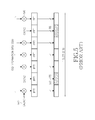
A structure for the CQI/PMI transmission in the PUCCH in one sub-frame slot is illustrated in FIG. 5 . The CQI transmission structure 510 includes the transmission of CQI signals and RS. The CQI bits 520 again are modulated, at block 530, according to a CAZAC sequence 540, for example using QPSK modulation, which is then transmitted after performing the IFFT operation. Each RS 550 is again transmitted through the unmodulated CAZAC sequence.
An example of CAZAC sequences is determined according to
where L is the length of the CAZAC sequence, n is the index of an element of the sequence n={0, 1, . . . , L−1}, and k is the index of the sequence. If L is a prime integer, there are L−1 distinct sequences which are defined as k ranges in {0, 1, . . . , L−1}. If a PRB includes an even number of REs, such as, for example, Nsc RB=12, CAZAC sequences with an even length can be directly generated through a computer search for sequences satisfying the CAZAC properties.
Reverse (complementary) transmitter operations of the operations illustrated in FIG. 6 are performed for the reception of the CAZAC sequence, as illustrated in FIG. 7 . Referring to FIG. 7 , an antenna receives an RF analog signal at block 710. After processing by processing units such as filters, amplifiers, frequency down-converters, and analog-to-digital converters (not shown), the received digital is filtered at block 720 and the CP is removed at block 730. Subsequently, the CS is restored at block 740, a Fast Fourier Transform (FFT) is applied at block 750, and the transmitted REs are selected at block 765 based on information from the SA or from higher layer signaling. FIG. 7 also shows the subsequent correlation 770 with the replica 780 of the CAZAC sequence in order to obtain an estimate of the channel medium (possibly modulated by HARQ-ACK information or CQI information as shown in FIG. 4 or FIG. 5 , respectively). Finally, the output 790 is obtained, which can then be passed to a channel estimation unit, such as a time-frequency interpolator, in case of a RS, or can to detect the transmitted information, in case the CAZAC sequence is modulated by HARQ-ACK information or CQI.
When UCI and data transmission occur in the same sub-frame, UCI may be transmitted together with data in the PUSCH or separately from data in the PUCCH. Including UCI in the PUSCH avoids simultaneous PUSCH and PUCCH transmissions, thereby conserving transmission power and avoiding an increase in the Peak-to-Average Power Ratio (PAPR) or the Cubic Metric (CM) of the combined signal transmission. Conversely, separately transmitting UCI in the PUCCH preserves PUSCH REs for data transmission and utilizes pre-allocated PUCCH resources. The required transmission power can be one of the conditions used to decide whether to simultaneously transmit PUCCH and PUSCH, to transmit UCI with data in the PUSCH, or to even transmit only UCI in the PUCCH and suspend the PUSCH transmission.
Transmission Power Control (TPC) adjusts the PUSCH or PUCCH transmission power to achieve a desired target for the received Signal to Interference and Noise Ratio (SINR) at the Node B, while reducing the interference to neighboring cells and controlling the rise of Interference over Thermal (IoT) noise, thereby ensuring the respective reception reliability targets. Open-Loop (OL) TPC with cell-specific and UE-specific parameters is considered with the capability for the Node B to also provide Closed Loop (CL) corrections through TPC commands. The TPC commands are included either in the SA configuring a dynamic PDSCH reception (TPC command adjusts the subsequent HARQ-ACK signal transmission power) or PUSCH transmission (TPC command adjusts the PUSCH transmission power), or are provided through a channel in the PDCCH carrying TPC commands (TPC channel) for PUSCH or PUCCH transmissions configured to occur periodically.
A TPC operation is described as follows based on the TPC operation used in 3rd Generation Partnership Project (3GPP) Evolved-Universal Terrestrial Radio Access (E-UTRA) Long Term Evolution (LTE). The PUSCH transmission power from a UE in reference sub-frame i is set according to Equation (1):
P PUSCH(i)=min{P MAX,10·log10 M PUSCH(i)+P 0 _ PUSCH +α·PL+Δ TF(i)+f(i)}[dBm] (1)
where
P PUSCH(i)=min{P MAX,10·log10 M PUSCH(i)+P 0 _ PUSCH +α·PL+Δ TF(i)+f(i)}[dBm] (1)
where
-
- PMAX is the maximum allowed power configured by RRC and can depend on the UE power amplifier class.
- MPUSCH, (i) is the number of (contiguous) PRBs for PUSCH transmission.
- P0 _ PUSCH controls the mean received SINR at the Node B and is the sum of a cell-specific component PO _ NOMINAL _ PUSCH and a UE-specific component PO _ UE _ PUSCH provided by RRC.
- PL is the DL path-loss estimate from the serving Node B as calculated in the UE.
- a is a cell-specific parameter provided by RRC with 0≦α≦1. Fractional TPC is obtained for α<1 as the path-loss is not fully compensated. For α=0, pure CL TPC is provided.
- ΔTF(i)=10·log10(2K
a ·TBS(i)/NRE (i)−1) where K>0 is a UE-specific parameter provided by RRC, TBS(i) is the TB size, and NRE(i)=MPUSCH(i)·Nsc RB·Nsymb PUSCH(i). Therefore, TBS(i)/NRE(i) defines the number of coded information bits per RE (Spectral Efficiency (SE)). If Ks>1, such as Ks=1.25, ΔTF(i) enables TPC based on the SE of the PUSCH transmission. TPC based on the SE of the PUSCH transmission is useful when the adaptation of the PUSCH Modulation and Coding Scheme (MCS) is slow and tracks only the path-loss. With MCS adaptation per PUSCH transmission, PUSCH power variations depending on SE should be avoided and this is achieved by setting Ks=0. - f(i)=f(i−1)+δPUSCH(i) is the function accumulating the CL TPC command δPUSCH(i) included in the SA configuring the PUSCH transmission in sub-frame i, or in a TPC channel in the PDCCH, with f(0) being the first value after reset of accumulation.
The PUCCH transmission power PPUCCH, from a UE in reference sub-frame i is set according to Equation (2):
P PUCCH(i)=min{P MAX ,P 0 _ PUCCH +PL+h(•)+ΔF _ PUCCH +g(i)}[dBm] (2)
where
P PUCCH(i)=min{P MAX ,P 0 _ PUCCH +PL+h(•)+ΔF _ PUCCH +g(i)}[dBm] (2)
where
-
- P0 _ PUCCH controls the mean received SINR at the Node B and is the sum of a cell-specific component PO _ NOMINAL _ PUCCH and a UE-specific component Po provided by RRC.
- h(•) is a function with values depending on whether HARQ-ACK, SR, or CQI is transmitted.
- ΔF _ PUCCH is provided by RRC and its value depends on the transmitted UCI type.
- g(i)=g(i−1)+δPUCCH(i) is the function accumulating the CL TPC command δPUCCH(i) in the PDCCH TPC channel or in the SA configuring the PDSCH reception and g(0) is the value after reset of accumulation.
For the SRS, in order to avoid large power variations within sub-frame symbols when the UE transmits PUSCH and SRS in the same sub-frame i, the transmission power PSRS follows the PUSCH transmission power and is set according to Equation (3):
P SRS(i)min{P MAX ,P SRS _ OFFSET+10·log10 M SRS +P 0 _ PUSCH +α·PL+f(i)}[dBm] (3)
where
P SRS(i)min{P MAX ,P SRS _ OFFSET+10·log10 M SRS +P 0 _ PUSCH +α·PL+f(i)}[dBm] (3)
where
-
- PSRS _ OFFSET is a UE-specific parameter semi-statically configured by RRC
- MSRS is the SRS transmission BW expressed in number of PRBs.
In order to support data rates higher than data rates possible in legacy communication systems and further improve the spectral efficiency, BWs larger than BWs of a Component Carrier (CC) for legacy systems are needed. These larger BWs can be achieved through the aggregation of multiple legacy CCs. For example, a BW of 60 MHz is achieved by aggregating three 20 MHz CCs. A UE may perform multiple PUSCH transmissions during the same sub-frame in the respective UL CCs. FIG. 8 illustrates aggregation of multiple legacy CCs, where a UE has three PUSCH transmissions, PUSCH 1 810, PUSCH 2 820 and PUSCH 3 830, in parts of the BW of three respective UL CCs, UC CC1 840, UC CC2 850, and UL CC3 860, during the same sub-frame.
The TPC operation should therefore be extended to PUSCH transmissions from a UE in multiple UL CCs during the same sub-frame. Additionally, as PUSCH and PUCCH transmissions from a UE in the same sub-frame and in the same or different UL CCs are also supported, the TPC operation should also include the combined operation for the PUSCH TPC and the PUCCH TPC. As a UE may also have multiple PUCCH transmissions in the same sub-frame and in the same or different UL CCs, the PUCCH TPC operation should also include support for multiple PUCCH transmissions. As a UE may have multiple transmitter antennas, the TPC operation should support the signal transmission from multiple antennas.
Therefore, there is a need to define the PUSCH TPC operation for multiple PUSCH transmissions from a UE in the same sub-frame in the same UL CC and in multiple UL CCs. There is also a need to define the PUCCH TPC operation for multiple PUCCH transmissions, of the same or different UCI signals, from a UE in the same sub-frame in the same UL CC and in multiple UL CCs. There is also a need to define the TPC operation for multiple UE transmitter antennas. There is also a need to define the combined PUSCH and PUCCH TPC operation for multiple PUSCH transmissions and PUCCH transmissions from a UE in the same sub-frame in the same UL CC and in multiple UL CCs.
Accordingly, the present invention has been designed to solve at least the aforementioned limitations in the prior art. The present invention also provides methods and apparatuses for the TPC application to simultaneous PUSCH transmissions in multiple CCs, to simultaneous transmissions of different UCI types, to simultaneous PUSCH and PUCCH transmissions, and to signal transmissions from multiple UE transmitter antennas having respectively multiple power amplifiers.
In accordance with an aspect of the present invention, there is provided a method for wireless communication by a user equipment (UE), including determining a first power for transmitting first control information on a physical uplink control channel (PUCCH), determining a second power for transmitting both first data and second control information on a first physical uplink shared channel (PUSCH), determining a third power for transmitting second data on a second PUSCH, reducing the third power if a sum of the first power, the second power and the third power exceeds a predetermined value, and transmitting at least one of the first control information on the PUCCH using the first power, the first data and the second control information on the first PUSCH using the second power, and the second data on the second PUSCH using the reduced third power.
In accordance with another aspect of the present invention, there is provided an apparatus for wireless communication in a UE, including a controller adapted to determine a first power for transmitting first control information on a PUCCH, to determine a second power for transmitting both first data and second control information on a first PUSCH, to determine a third power for second data on a second PUSCH, and to reduce the third power if a sum of the first power, the second power, and the third power exceeds a predetermined value, and a transmitter adapted to transmit at least one of the first control information on the PUCCH using the first power, the first data and the second control information on the first PUSCH using the second power, and the second data on the second PUSCH using the reduced third power.
In accordance with another aspect of the present invention, there is provided a method for wireless communication by a base station, including configuring a UE with a PUCCH conveying first control information, a first PUSCH conveying both first data and second control information, and a second PUSCH conveying second data, transmitting parameters required for transmission power control of the PUCCH and the first and second PUSCHs, and receiving, from the UE, at least one of the first control information on the PUCCH, the first data and the second control information on the first PUSCH, and the second data on the second PUSCH, wherein if a sum of a first power determined for transmitting the PUCCH by the UE, a second power determined for transmitting the first PUSCH by the UE, and a third power determined for transmitting the second PUSCH by the UE exceeds a predetermined value, the third power is reduced, and wherein the PUCCH is transmitted with the first power, the first PUSCH is transmitted with the second power, and the second PUSCH is transmitted with the reduced third power.
In accordance with another aspect of the present invention, there is provided an apparatus for wireless communication in a base station, including a controller adapted to configure a UE with a PUCCH conveying first control information, a first physical uplink shared channel (PUSCH) conveying both first data and second control information, and a second PUSCH conveying second data, a transmitter adapted to transmit parameters required for transmission power control of the PUCCH and the first and second PUSCHs, and a receiver adapted to receive, from the UE, at least one of the first control information on the PUCCH, the first data and the second control information on the first PUSCH, and the second data on the second PUSCH, wherein if a sum of a first power determined for transmitting the PUCCH by the UE, a second power determined for transmitting the first PUSCH by the UE and a third power determined for transmitting the second PUSCH by the UE exceeds a predetermined value, the third power is reduced, and wherein the PUCCH is transmitted with the first power, the first PUSCH is transmitted with the second power and the second PUSCH is transmitted with the reduced third power.
The above and other aspects, features, and advantages of the present invention will be more apparent from the following detailed description taken in conjunction with the accompanying drawings, in which:
Hereinafter, various embodiments of the present invention will be described with reference to the accompanying drawings. A detailed description of known functions and configurations incorporated herein will be omitted when it may obscure the subject matter of the present invention.
Although the present invention is described in relation to an Orthogonal Frequency Division Multiple Access (OFDMA) communication system, the present invention may also be applied to all Frequency Division Multiplexing (FDM) systems generally, including Single-Carrier Frequency Division Multiple Access (SC-FDMA), OFDM, FDMA, Discrete Fourier Transform (DFT)-spread OFDM, DFT-spread OFDMA, SC-OFDMA, and SC-OFDM.
A first aspect of the invention considers a PUSCH TPC operation for multiple PUSCH transmissions from a UE in a sub-frame in the same UL CC and in multiple UL CCs. According to an embodiment of the present invention, the TPC formula for the PUSCH transmission power in a single CC and over contiguous PRBs also applies, per UL CC, for PUSCH transmission in multiple UL CCs and over contiguous or non-contiguous PRBs. Then, the PUSCH transmission power PPUSCH(i,k) from a UE in sub-frame i and UL CC k, k=1, . . . , K, is set as
where
-
- MPUSCH (i,k) is the number of, contiguous or non-contiguous, PRBs for PUSCH transmission in UL CC k.
- P0 _ PUSCH (k) controls the mean received SINR at the Node B and is the sum of a cell-specific component PO _ NOMINAL _ PUSCH and a UE-specific component PO _ UE _ PUSCH (k) which are provided to the UE by RRC.
- α(k) is a cell-specific parameter provided by RRC for UL CC k with 0≦α(k)≦1.
- PL(k) is the DL path-loss estimate from the serving Node B as calculated at the UE and applied to UL CC k.
- ΔTF(i,k)=10·log10(2K
s (k)·TBS(i,k)/NRE (i,k)−1) where Ks(k) is a parameter provided by RRC in UL CC k, TBS(i,k) is the TB size, and NRE(i,k)=MPUSCH(i,k)·Nsc RB·Nsymb PUSCH(i,k). - f(i,k)=f(i−1,k)+δPUSCH(i,k) is the function accumulating the CL TPC command δPUSCH(i,k) during sub-frame i with f(0, k) being the first value after reset of accumulation. If the PUSCH transmission in UL CC k is configured through a SA, the CL TPC command δPUSCH(i,k) is included in that SA. Otherwise, a TPC channel in the PDCCH informs the UE of the CL TPC command δPUSCH(i,k).
While the TPC formula in Equation (4) is a generalization of the TPC formula for PUSCH transmission in a single UL CC in Equation (1), Equation (4) raises several issues including:
-
- a) whether to define UL CC specific parameters,
- b) how the UE performs UL CC specific DL path-loss measurements and accumulation of CL TPC commands, and
- c) how to allocate the power for PUSCH transmissions in multiple UL CCs in case PMAX is reached before the PUSCH transmission in each UL CC is allocated its target power.
Regarding the definition of UL CC specific parameters, direct extension of all parameters to CC-specific values or the following restrictions may be considered:
-
- P0 _ PUSCH(k): The cell-specific component PO _ NOMINAL _ PUSCH (k) may be common to all UL CCs while the UE-specific component Po (k) may be different for each UL CC.
- α(k) is a cell-specific parameter provided by RRC for each UL CC k.
- Ks(k) in ΔTF(i,k) may be common to all UL CCs a UE is configured since either adaptive MCS selection applies to all UL CCs (Ks=0) or to none of them (for example, Ks=1.25).
Regarding the UL CC specific DL path-loss measurements and accumulation of the CL TPC commands at the UE, the following restrictions may be considered:
-
- PL(k): Path-loss measurements on each UL CC are not needed for BW contiguous UL CCs but are needed for BW non-contiguous UL CCs. Since it is desirable for the UE functionality to not differentiate between the cases of BW contiguous and BW non-contiguous UL CCs, path-loss measurements on multiple UL CCs are supported. Moreover, each UE can be configured an UL CC which is linked to a DL CC where the UE performs the path-loss measurement. The UE uses that UL CC to report the path-loss measurement. The Node B informs each UE through RRC whether additional path-loss measurements need to be performed for the remaining UL CCs a UE is configured, which are linked to respective DL CCs. The Node B may also inform the UEs of the path-loss measurement reporting rate.
- f(i,k): Accumulation of CL TPC commands each UL CC k is always performed in the same manner as PUSCH transmission in a single UL CC. However, in case of PUSCH transmissions in multiple UL CCs or in case of concurrent PUCCH transmissions, PMAX may be reached before each channel is allocated its nominal transmission power. Then, as it is subsequently discussed, the transmission power of the various channels is reduced. This reduction may lead to the suspension of PUSCH transmission in an UL CC. In such case, CL TPC commands are always accumulated in each respective UL CC even when a respective PUSCH transmission is suspended.
Regarding the PUSCH transmission power allocation among multiple UL CCs when PMAX is reached before the PUSCH transmission in each UL CC is allocated its nominal power according Equation (4), one option is to reduce the PUSCH transmission power in each UL CC by the same amount so that the total transmission power does not exceed PMAX. However, this reduction option effectively penalizes PUSCH transmissions of higher Spectral Efficiency (SE) more than this reduction option penalizes PUSCH transmissions with lower SE, and therefore, this option is detrimental. Additionally, this reduction option may lead to the suspension of PUSCH transmissions having a low nominal power.
Embodiments according to the present invention consider that the same amount of power reduction is applied only to PUSCH transmissions in non-contiguous BWs in the same UL CC, which are assumed to have the same SE (or MCS). PUSCH transmissions in different UL CCs are allowed to have different SEs (or MCSs) and two approaches are subsequently described herein for adjusting the transmission power when the total UE transmission power exceeds PMAX. The same principle applies in each of the two approaches. For some PUSCH transmissions, it is possible to avoid any power reduction while, for the remaining PUSCH transmissions, the adjusted power is proportional to the SINR or to the nominal transmission power.
The first approach considers that the amount of allocated power is proportional to the SINR of the PUSCH transmission. The SE in UL CC k can be expressed as the ratio TBS(i,k)/NRE(i,k) providing the number of coded information bits per RE. Then, the Shannon capacity formula is applied according to Equation (5),
where f is a normalizing factor such as Ks, and (I+N)(i,k) is the sum of interference and noise power in UL CC k. Therefore,
by approximation,
as the SINR for UEs scheduled PUSCH transmissions in multiple UL CCs is typically sufficiently larger than 1 (in the linear domain). When the nominal PUSCH transmission power according to Equation (4) cannot be allocated in any respective UL CC, in order to obtain a proportional reduction to the SINR, the PUSCH transmission power in UL CC k is derived according to Equation (6):
A procedure for allocating the power to PUSCH transmissions in multiple UL CCs, when the total nominal transmission power exceeds PMAX, includes the following steps:
-
- a) Determine the UL CCs, if any, for which
and create a set J with the respective indexes, J={1, . . . , J0}. In these UL CCs, the PUSCH transmission power remains unchanged and is as described in Equation (4).
-
- b) For the remaining UL CCs, k∈{1, . . . , K}, k∉J, the PUSCH transmission power is determined according to Equation (8):
The preceding procedure ensures, that in an UL CC where the nominal PUSCH transmission power is lower than the respective transmission power in Equation (6), the nominal PUSCH transmission power is applied according Equation (4) and the sum of nominal PUSCH transmission powers is subtracted from PMAX prior to adjusting the power of PUSCH transmissions in the remaining UL CCs.
Moreover, the above procedure may be implemented in an iterative fashion, wherein the second step b) is further divided into 2 sub-steps, where in the first sub-step the UL CCs for which PPUSCH adjust(i,k)=PPUSCH(i,k) are identified, if any, another set J1={1, . . . , J0 1} with the respective indexes is created. In the second sub-step, Equation (8) is further refined as Equation (9):
The procedure can continue from the second sub-step in the same iterative manner with two more sub-sub-steps. However, the mechanisms of the first approach are evident from the preceding description and further details are omitted for clarity and conciseness.
An application for the first approach is described as follows. A reference UE is assumed to have PMAX=10, PUSCH transmissions in K=3 CCs in sub-frame i, and nominal transmission powers PPUSCH(i,1)=2, PPUSCH(i,2)=3, and PPUSCH(i,3)=7. The values for
Since
the
UE applies the previous procedure for the PUSCH transmission power allocation in each CC. From the first step a), the condition in Equation (7) applies only when k=1 and the nominal PUSCH transmission power PPUSCH(i,1)=2 is assigned. Therefore, the set J contains k=1. From the second step b), based on Equation (8), the PUSCH transmission power assigned for k=2,3 is respectively PPUSCH adjust(i,2)=3=PPUSCH adjust(i,2) and PPUSCH adjust(i,3)=24/5=4.8. The total allocated power is 9.8, which is less than PMAX=10. The total allocated power is less than PMAX, because the nominal PUSCH transmission power PPUSCH adjust(i,2)=PPUSCH(i,2)=3 is allocated instead of
which would have made the total allocated power equal to PMAX. As PPUSCH adjust(i,3)<PPUSCH(i,3) and PPUSCH(i,1)+PPUSCH(i,2)+PPUSCH adjust(i,3)<PMAX, it would be desirable to further increase PPUSCH adjust=(i,3). This further increase is achieved by the iterative part of the procedure where the set J1 contains k=2. Then, Equation (9) provides PPUSCH adjust(i,3)=5 (instead of PPUSCH adjust(i,3)=4.8 if no iterations were applied). Nevertheless, as previously mentioned, if a simplified PUSCH power allocation process is desired, the iterative steps of the procedure may be omitted.
A PUSCH power allocation using the first approach according to an embodiment of the present invention is illustrated in FIG. 9 . Referring to FIG. 9 , the UE first determines the nominal PUSCH transmission power PPUSCH (i,k) in each of the UL CCs where the UE has PUSCH transmission in step 910. Subsequently, the UE determines whether the aggregate of the nominal PUSCH transmission powers is less than PMAX in step 920. If the aggregate is less than PMAX is, the PUSCH transmission in an UL CC uses the respective nominal transmission power in step 930. If the aggregate of the nominal PUSCH transmission powers is at least equal to PMAX, the UE determines the PUSCH transmissions with
creates a set J with the respective UL CC indexes, and transmits PUSCH in those UL CCs using the nominal transmission power in
in
The second approach provides implementation simplicity and similar characteristics as the first approach in the linear range of the Shannon capacity curve and considers that the PUSCH transmission power is proportionally reduced relative to a nominal value according to Equation (10)
The procedure to allocate the power to PUSCH transmissions in multiple UL CCs in case the total nominal transmission power exceeds considers the following steps:
- c) Determine the UL CCs, if any, for which
-
- and create a set J with the respective indexes, J={1, . . . , J0}. In these UL CCs, the nominal PUSCH transmission power is applied as described in Equation (4).
- d) For the remaining UL CCs k E {1, . . . , K}, k∉J, the PUSCH transmission power is determined according to Equation (12):
Similar to the first approach, the preceding procedure ensures that in UL CCs where the nominal PUSCH transmission power is less than the respective one in Equation (10), the nominal PUSCH transmission power is applied according to Equation (4) and the sum of nominal PUSCH transmission powers is subtracted from PMAX before adjusting each PUSCH transmission power in the remaining UL CCs. Moreover, the preceding procedure may be implemented in an iterative fashion, wherein the second step d) is further divided into 2 sub-steps, wherein in the first sub-step of step d), the UL CCs for which PPUSCH adjust(i,k)=PPUSCH(i,k) are identified, if any, another set J1={1, . . . , J0 1} with the respective indexes is created, and in the second sub-step of step d) Equation (12) is further refined as Equation (13):
and continue from the second sub-step in the same iterative manner with two additional sub-sub-steps. Nevertheless, for the first approach, the mechanisms of the second approach are evident from the described procedure and further details are omitted for brevity. Additionally, for both the first approach and the second approach, the first step of the power allocation may be avoided in order to simplify the respective procedure (equivalent to the case that the set J is empty).
A PUSCH power allocation using the second approach according to an embodiment of the present invention is illustrated in FIG. 10 . Referring to FIG. 10 , the UE first determines the nominal PUSCH transmission power PPUSCH(i,k) in each respective UL CC in step 1010. Subsequently, the UE determines whether the aggregate of the nominal PUSCH transmission powers is less than PMAX, in step 1020. If the aggregate is less than PMAX, the UE transmits its PUSCH in the respective UL CC using the respective nominal transmission power in step 1030. If the aggregate of the nominal PUSCH transmission powers is at least equal to PMAX, the UE determines the PUSCH transmissions such that
creates a set J with the respective UL CCs indexes, and transmits PUSCH in those UL CCs using the nominal transmission power in
in
A method according to an embodiment of the present invention also consider that instead of SINRs or nominal transmission powers, the SEs (or the MCSs) can be used as metrics for determining PUSCH transmission power adjustments. Using the SEs of the PUSCH transmissions in UL CCs k∈{1, . . . , K} during sub-frame i as metrics, the PUSCH transmission power in UL CC k can be determined as
Using the MCSs of the PUSCH transmissions in UL CCs k∈{1, . . . , K} during sub-frame i as metrics, the PUSCH transmission power in UL CC k can be determined as
The two previously described approaches for the PUSCH power allocation when PMAX is reached assume that none of the PUSCH transmissions contains UCI and that the UE does not have any PUCCH transmissions. When neither of these assumptions holds, a method according to an embodiment of the present invention considers the following modifications to the PUSCH transmission power allocation:
-
- e) The nominal power is used for any PUSCH transmission containing UCI and it is included in the set J. The procedure to determine the power of the remaining PUSCH transmissions remains as previously described. If multiple PUSCH transmissions from a UE contain UCI and their combined transmission power exceeds PMAX, PUSCH transmissions with HARQ-ACK are prioritized over ones with other UCI types as it is subsequently described.
- f) If the UE also has PUCCH transmissions in the same sub-frame, the nominal power of the PUCCH transmissions is used and included in the set J. The procedure to determine the power of the remaining PUSCH transmissions is the same as the previously described procedure.
Modifications to the PUSCH transmission power allocation according to an embodiment of the present invention are illustrated in FIG. 11 . Referring to FIG. 11 , the UE first allocates power to its PUCCH transmissions, if any, over all respective UL CCs including potential multiple PUCCH transmissions in the same UL CC, and to its PUSCH transmissions including UCI, if any. The same UCI is not transmitted in both the PUCCH and the PUSCH in sub-frame i. The total power allocated to C PUCCH transmissions is set according to
and the total power allocated to U PUSCH transmissions with UCI is set according to
in
The PUSCH transmissions can be ranked in consideration of the presence of UCI, and the ranking can also extend in general to the UL CCs of the PUSCH transmission. For example, a UE can be configured by the Node B the UL CCs k∈{1, . . . , K} in order of significance, thereby ranking the UL CCs and having a primary UL CC, a secondary UL CC, etc., or this ranking can be in order of SINR, SE, MCI, or UCI type. For simplicity, the value of k now refers to the ranking of the UL CC for a particular UE, but not to the actual physical ordering of an UL CC with respect to the other UL CCs. Then, the PUSCH transmission power adjustment procedure starts from the L CC with the lowest rank and determines the respective adjustment to the PUSCH transmission power as
If PPUSCH adjust(i,K) is not negative, the PUSCH power adjustment process terminates and the PUSCH in each remaining UL CC k∈{1, . . . , K−1} is allocated the respective nominal transmission power. If PPUSCH adjust(i,K) is negative, PUSCH transmission in UL CC K is suspended and the PUSCH transmission power adjustment process continues to UL CC K−1. Then, PPUSCH adjust(i,K−1) is determined according to
Similarly, if PPUSCH adjust(i,K−1) is not negative, the PUSCH transmission power adjustment process terminates and the PUSCH in each of the remaining UL CCs k∈{1, . . . , K−2} is allocated the respective nominal transmission power. If PPUSCH adjust(i,K−1) is negative, PUSCH transmission in UL CC K−1 is also suspended and the PUSCH transmission power adjustment process continues to UL CC K−2 in the same manner. In general, the PUSCH power adjustment process terminates at UL CC k1>1 with
where k1 is the largest UL CC index satisfying the previous condition and, if k1<K, the PUSCH transmission in UL CCs k∈{k1+1, . . . , K} is suspended. If k1=1, the PUSCH transmission occurs only in the primary CC with PPUSCH adjust(i,1)=PMAX and it is suspended in all other UL CCs.
The TPC formula for the PUCCH transmission power from a UE in a single CC and over contiguous PRBs also applies, per UL CC, for PUCCH transmission in multiple UL CCs and over contiguous or non-contiguous PRBs. Then, the PUCCH transmission power PPUSCH(i,k) from a UE in sub-frame i and UL CC k is set according to Equation (14):
where
-
- P0 _ PUCCH(k) controls the mean received SINR at the Node B and is the sum of a cell-specific component PO _ NOMINAL _ PUCCH (k) and a UE-specific component PO _ UE _ PUCCH(k) which are provided to the UE by RRC.
- g(i,k)=g(i−1,k)+δPUCCH(i,k) is a function accumulating the CL TPC command δPUCCH(i,k) in the PDCCH TPC channel or in the SA configuring the PDSCH reception for UL CC k in sub-frame i.
- The parameters h(•) and ΔF _ PUCCH are the same as for a single PUCCH transmission in a single UL CC, while PL(k) is defined for the PUSCH transmission in UL CC k.
While the TPC formula in Equation (10) is a generalization of the TPC formula for a single PUCCH transmission in a single UL CC in Equation (2), the same issues as the issues for PUSCH transmissions in multiple UL CCs are raised including:
-
- a) whether to define UL CC specific parameters,
- b) how the UE performs UL CC specific DL path-loss measurements and accumulation of CL TPC commands, and
- c) how allocate PUCCH transmission power in multiple UL CCs in case PMAX is reached before the PUCCH transmission in each UL CC is allocated its target transmission power.
Regarding the definition of UL CC specific parameters, direct extension of all parameters to CC-specific values or the following restrictions may be considered:
-
- P0 _ PUCCH(k): The cell-specific component PO _ NOMINAL _ PUCCH(k) may be common for all UL CCs while the UE-specific component PO _ UE _ PUCCH(k) may be different for each UL CC.
Regarding the path-loss measurements and the accumulation of CL TPC commands at the UE, the following may be considered:
-
- PL(k): The aspects for DL path-loss measurements are the same as corresponding aspects for the PUSCH TPC operation.
- g(i,k): Accumulation of CL TPC commands in each UL CC k is performed in the same manner as for PUCCH transmission in a single UL CC. However, in case of PUCCH transmissions in multiple UL CCs, PMAX may be reached before each channel is allocated its nominal transmission power. As it is later discussed, this may result to the suspension of a PUCCH transmission. The invention considers that the CL TPC commands for a respective PUCCH transmission are always accumulated in the respective UL CC even when the transmission is suspended.
Regarding the PUCCH transmission power allocation among multiple UCI signals when PMAX is reached before the nominal PUCCH transmission is allocated in each UCI signal, the invention considers the following principles:
-
- Transmission power for HARQ-ACK signaling is unaffected and is allocated first.
- If there are multiple HARQ-ACK channels and PMAX is reached, a proportional decrease in the nominal transmission power is applied as the proportional decrease was previously described according to the second approach for the PUSCH transmission power allocation.
- Transmission power for SR signaling is allocated next. SR transmission is always used in the resources of a single UL CC configured to the UE through RRC signaling. If PMAX is reached before the SR signaling is allocated its nominal transmission power, two options exist:
- Drop the SR transmission (by default if the power for HARQ-ACK signaling is PMAX).
- Transmit the SR with reduced power.
- As a false positive SR is less detrimental for the overall system operation than a missed/dropped SR, the invention considers the second option. Therefore, the SR transmission power PPUCCH _ SR adjust(i) in sub-frame i in the configured UL CC is given by Equation (15)
- Transmission power for HARQ-ACK signaling is unaffected and is allocated first.
-
- where PPUCCH _ SR(I) is the nominal, unadjusted, SR transmission power, PPUCCH _ ACK/NAK(i,j) is the HARQ-ACK transmission power in UL CC j and J HARQ-ACK is the total number of UL CCs having HARQ-ACK transmission. When the HARQ-ACK and SR transmissions can be multiplexed in the same channel, as in 3GPP E-UTRA LTE, separate consideration of SR and HARQ-ACK transmissions is not needed.
- Transmission power for CQI signaling is allocated next. If PMAX is reached before the CQI signaling is allocated its nominal transmission power, two options exist:
- Drop the CQI transmission (which is a default if the power for HARQ-ACK and/or SR signaling is PMAX).
- Transmit CQI with reduced power.
- The first option is less detrimental as it is preferable for the UE to conserve power and for the Node B to be informed that a CQI report has been missed/dropped (for example, through detection of the CQI transmission absence) than to receive an incorrect CQI report or to ignore the CQI report. The second option may be preferable when the PUCCH CQI transmission is performed over multiple sub-frames and/or has Cyclic Redundancy Check (CRC) protection. Then, the CQI transmission power PPUCCH _ CQI adjust(i,k) in sub-frame i and UL CC k is given according to Equation (16):
-
- where PPUCCH _ CQI(i,k) is the nominal CQI transmission power. In case of CQI transmissions in multiple UL CCs during sub-frame i, if the total power remaining after the power allocation to HARQ-ACK and/or SR transmission is not sufficient to provide the nominal CQI transmission power in each UL CC, the power allocation follows the same principles as in either of the two approaches for the PUSCH power allocation.
The above principles also apply when UCI is included in the PUSCH. In general, power is allocated with highest priority to a channel with HARQ-ACK signaling, followed by SR signaling, while power for CQI signaling is allocated with the lowest priority.
A prioritization of power allocation according to an embodiment of the present invention is illustrated in FIG. 12 . Referring to FIG. 12 , the existence of HARQ-ACK information for transmission in the reference sub-frame is first determined in step 1210. If there is HARQ-ACK information for transmission either in the PUSCH or in the PUCCH, the respective power is first allocated in step 1212. No reduction in the transmission power is applied unless PMAX is reached, in which case the transmission power of each channel, if more than one, is proportionally reduced as previously described. The allocated power is subtracted from PMAX to obtain a remaining power PMAX rem and, for the subsequent operation of the power allocation procedure, PMAX rem is set to PMAX, in step 1214. If PMAX>0, or if there is no HARQ-ACK transmission, the power allocation process continues to step 1216; otherwise, the power allocation process ends in step 1218 and no additional channels are transmitted by the reference UE.
The existence of SR information in the reference sub-frame is subsequently determined in step 1220. If there is SR information for transmission either in the PUSCH or in the PUCCH, the respective power is allocated in step 1222. No reduction in the transmission power is applied unless PMAX is reached (in the method according to FIG. 12 it is assumed that SR is transmitted only through one PUCCH or in a PUSCH as part of data information). The allocated power is subtracted from PMAX to obtain a remaining power M for the subsequent operation of the power allocation procedure, PMAX rem is set to PMAX in step 1224. If PMAX>0, or if there is no SR transmission, the power allocation process continues in step 1226; otherwise, the power allocation process ends and no additional channels are transmitted by the reference UE in step 1228.
The existence of CQI for transmission in the reference sub-frame is subsequently determined in step 1230. If there is CQI for transmission either in the PUSCH or in the PUCCH, the respective power is allocated in step 1232. No reduction in the transmission power is applied unless PMAX is reached. If it is determined that power reduction is needed in step 1234, the UE determines whether the CQI transmission is CRC protected in step 1236. If the CQI transmission is not CRC protected, the CQI transmission in the PUCCH is dropped in step 1238. If there is CRC protection, or if the CQI transmission is in the PUSCH, the allocated power is subtracted from PMAX to obtain a remaining power PMAX rem and, for the subsequent operation of the power allocation procedure, PMAX rem is set to PMAX in step 1240. If PMAX>0 or if there is no CQI transmission, the power allocation process continues in step 1242; otherwise, the power allocation process ends and no additional channels are transmitted by the reference UE in step 1244.
The TPC formula for the power of the SRS transmission from a UE in a single CC can also be applied, per UL CC, for SRS transmission in multiple UL CCs. Then, the SRS transmission power PSRS(i,k) from a UE in sub-frame i and UL CC k is set according to Equation (17)
where
-
- PSRS _ OFFSET (k) controls the mean received SINR at the Node B and is provided to the UE by RRC signaling.
- MSRS(k) is the SRS transmission BW, in PRBs, in UL CC k.
- The remaining parameters are as defined for PUSCH transmission in UL CC k.
The TPC formula in Equation (17) is a generalization of the formula in Equation (3). However, even though PSRS _ OFFSET is a UE-specific parameter, PSRS _ OFFSET may be separately configured in each UL CC, since the Power Spectral Density (PSD) of the SRS transmission tracks the PSD of the PUSCH transmission. Also, the parameter P0 _ PUSCH(k) can be configured in each UL CC and the SRS transmission BW, as defined by a number of PRBs, can differ among UL CCs (for example, the PUCCH size or SRS multiplexing capacity may differ among UL CCs or the UL CCs may have different BW) and the value of MSRS(k) can depend on the UL CC k.
Regarding the SRS transmission power allocation in multiple UL CCs when PMAX is reached before the nominal SRS transmission power is allocated in each UL CC, the same approaches as the approaches described for the PUSCH transmission can be followed, such that, for the first approach, MSRS(k) replaces SE(i,k) and Equation (8) is modified as Equation (18):
while Equation (12) applies as is with PSRS replacing PPUSCH.
The TPC operation can be extended to multiple UE transmitter antennas wherein each antenna, M∈{1, . . . , M}, has its own Power Amplifier (PA). Since the extensions of the TPC operation for the PUCCH and SRS are straightforward, for clarity and conciseness, the TPC extension operation for only for the PUSCH is described as follows.
Each UE transmitter antenna may have a different class of PA and therefore PMAX may depend on the UE antenna. Furthermore, due to its position, each antenna may experience a different path loss, and therefore a respective measurement is required for each antenna. The remaining parameters in the TPC formula are the same for all antennas. For UE transmitter antenna m, the TPC formula for the PUSCH transmission power in Equation (4) is modified as Equation (19):
P PUSCH(i,k,m)=min{P MAX(m),10·log10 M PUSCH(i,k)+P 0 _ PUSCH(k)+α(k)·PL(k,m)+ΔTF(i,k)+f(i,k)}[dBm] (19)
where
P PUSCH(i,k,m)=min{P MAX(m),10·log10 M PUSCH(i,k)+P 0 _ PUSCH(k)+α(k)·PL(k,m)+ΔTF(i,k)+f(i,k)}[dBm] (19)
where
-
- PMAX (m) is the maximum transmission power from UE transmitter antenna m.
- PL(k,m) is the DL path-loss estimate as calculated in the UE using antenna m.
The same value for α(k) is assumed for all UE transmitter antennas and the PUSCH is transmitted with the same parameters from all UE transmitter antennas.
A TPC operation for multiple UE transmitter antennas according to an embodiment of the present invention is illustrated in FIG. 13 . Referring to FIG. 13 , RRC configures, to a reference UE, the cell-specific parameter a(k) and the parameters P0,PUSCH(k) and Ks in UL CC k. RRC may also configure, to the UE, the parameter PMAX(m) for each UE transmitter antenna m with a separate PA (m∈{1, . . . , M}) in step 1310. The UE measures the DL path-loss PL(k,m) for transmitter antenna m in step 1320 and, based on the PUSCH transmission parameters in UL CC k, the UE computes the nominal PUSCH transmission power for transmitter antenna m as in Equation (19) in step 1330.
The CL TPC commands can differ for each UE transmitter antenna, since the signal propagation conditions may not be correlated. Therefore, by enabling CL TPC per antenna, the overall TPC operation can be improved and the respective formula for the PUSCH transmission power becomes
P PUSCH(i,k,m)=min{P MAX(m),10·log10 M PUSCH(i,k)+P 0 _ PUSCH(k)+α(k)·PL(k,m)+ΔTF(i,k)+f(i,k,m)}[dBm] (20)
where
P PUSCH(i,k,m)=min{P MAX(m),10·log10 M PUSCH(i,k)+P 0 _ PUSCH(k)+α(k)·PL(k,m)+ΔTF(i,k)+f(i,k,m)}[dBm] (20)
where
-
- f(j,k,m)=f(i−1,k,m)+PUSCH(i,k,m) is the function accumulating the CL TPC command δPUSCH(i,k,m) for UE transmitter antenna m, which is included in the PDCCH TPC channel or in the SA configuring the PUSCH transmission in UL CC k during sub-frame i.
A TPC operation with different CL TPC command per UE transmitter antenna m with a separate PA (m∈{1, . . . , M}) according to an embodiment of the present invention is illustrated in FIG. 14 . Referring to FIG. 14 , RRC configures, to the reference UE, the parameters P0,PUSCH(k), Ks, and α(k) in UL CC k and the parameter PMAX(m) for each UE transmitter antenna m in step 1410. The UE measures the DL path-loss PL(k,m) for each transmitter antenna m in step 1420. The UE receives the CL TPC commands for each transmitter antenna m in the SA configuring the PUSCH transmission parameters (or in a PDCCH TPC channel) in step 1430. Based on the PUSCH transmission parameters in UL CC k, the UE computes the nominal PUSCH transmission power for transmitter antenna m as in Equation (20) in step 1440.
While the present invention has been shown and described with reference to certain preferred embodiments thereof, the present invention is not limited to these embodiments. Further, it will be understood by those skilled in the art that various changes in form and details may be made therein without departing from the spirit and scope of the present invention as defined by the appended claims.
Claims (24)
1. A method for wireless communication by a user equipment (UE), comprising:
determining a first power for transmitting first control information on a physical uplink control channel (PUCCH);
determining a second power for transmitting both first data and second control information on a first physical uplink shared channel (PUSCH);
determining a third power for transmitting second data on a second PUSCH;
reducing the third power if a sum of the first power, the second power and the third power exceeds a predetermined value; and
transmitting at least one of the first control information on the PUCCH using the first power, the first data and the second control information on the first PUSCH using the second power, and the second data on the second PUSCH using the reduced third power.
2. The method of claim 1 , wherein the reduced third power is less than or equal to a value obtained by subtracting the first power and the second power from the predetermined value.
3. The method of claim 1 , wherein the predetermined value is a maximum power allowed for the UE.
4. The method of claim 1 , wherein the second control information comprises at least one of a Hybrid Automatic Repeat reQuest ACKnowledgment (HARQ-ACK) and channel quality information.
5. The method of claim 1 , wherein the first and second PUSCHs are transmitted in respective component carriers.
6. The method of claim 1 , further comprising reducing the second power if a sum of the first power, the second power and the reduced third power exceeds the predetermined value.
7. An apparatus for wireless communication in a user equipment (UE), comprising:
a controller adapted to determine a first power for transmitting first control information on a physical uplink control channel (PUCCH), to determine a second power for transmitting both first data and second control information on a first physical uplink shared channel (PUSCH), to determine a third power for second data on a second PUSCH, and to reduce the third power if a sum of the first power, the second power, and the third power exceeds a predetermined value; and
a transmitter adapted to transmit at least one of the first control information on the PUCCH using the first power, the first data and the second control information on the first PUSCH using the second power, and the second data on the second PUSCH using the reduced third power.
8. The apparatus of claim 7 , wherein the reduced third power is less than or equal to a value obtained by subtracting the first power and the second power from the predetermined value.
9. The apparatus of claim 7 , wherein the predetermined value is a maximum power allowed for the UE.
10. The apparatus of claim 7 , wherein the second control information comprises at least one of a Hybrid Automatic Repeat reQuest ACKnowledgment (HARQ-ACK) and channel quality information.
11. The apparatus of claim 7 , wherein the first and second PUSCHs are transmitted in respective component carriers.
12. The apparatus of claim 7 , further comprising reducing the second power if a sum of the first power, the second power and the reduced third power exceeds the predetermined value.
13. A method for wireless communication by a base station, comprising:
configuring a user equipment (UE) with a physical uplink control channel (PUCCH) conveying first control information, a first physical uplink shared channel (PUSCH) conveying both first data and second control information, and a second PUSCH conveying second data;
transmitting parameters required for transmission power control of the PUCCH and the first and second PUSCHs; and
receiving, from the UE, at least one of the first control information on the PUCCH, the first data and the second control information on the first PUSCH, and the second data on the second PUSCH,
wherein if a sum of a first power determined for transmitting the PUCCH by the UE, a second power determined for transmitting the first PUSCH by the UE, and a third power determined for transmitting the second PUSCH by the UE exceeds a predetermined value, the third power is reduced, and
wherein the PUCCH is transmitted with the first power, the first PUSCH is transmitted with the second power, and the second PUSCH is transmitted with the reduced third power.
14. The method of claim 13 , wherein the reduced third power is less than or equal to a value obtained by subtracting the first power and the second power from the predetermined value.
15. The method of claim 13 , wherein the predetermined value is a maximum power allowed for the UE.
16. The method of claim 13 , wherein the second control information comprises at least one of a Hybrid Automatic Repeat reQuest ACKnowledgment (HARQ-ACK) and channel quality information.
17. The method of claim 13 , wherein the first and second PUSCHs are transmitted in respective component carriers.
18. The method of claim 13 , wherein the second power is reduced if a sum of the first power, the second power and the reduced third power exceeds the predetermined value.
19. An apparatus for wireless communication in a base station, comprising:
a controller adapted to configure a user equipment (UE) with a physical uplink control channel (PUCCH) conveying first control information, a first physical uplink shared channel (PUSCH) conveying both first data and second control information, and a second PUSCH conveying second data;
a transmitter adapted to transmit parameters required for transmission power control of the PUCCH and the first and second PUSCHs; and
a receiver adapted to receive, from the UE, at least one of the first control information on the PUCCH, the first data and the second control information on the first PUSCH, and the second data on the second PUSCH,
wherein if a sum of a first power determined for transmitting the PUCCH by the UE, a second power determined for transmitting the first PUSCH by the UE and a third power determined for transmitting the second PUSCH by the UE exceeds a predetermined value, the third power is reduced, and
wherein the PUCCH is transmitted with the first power, the first PUSCH is transmitted with the second power and the second PUSCH is transmitted with the reduced third power.
20. The apparatus of claim 19 , wherein the reduced third power is less than or equal to a value obtained by subtracting the first power and the second power from the predetermined value.
21. The apparatus of claim 19 , wherein the predetermined value is a maximum power allowed for the UE.
22. The apparatus of claim 19 , wherein the second control information comprises at least one of a Hybrid Automatic Repeat reQuest ACKnowledgment (HARQ-ACK) and channel quality information.
23. The apparatus of claim 19 , wherein the first and second PUSCHs are transmitted in respective component carriers.
24. The apparatus of claim 19 , wherein the second power is reduced if a sum of the first power, the second power and the reduced third power exceeds the predetermined value.
Priority Applications (1)
| Application Number | Priority Date | Filing Date | Title |
|---|---|---|---|
| US14/859,989 US9414323B2 (en) | 2009-03-17 | 2015-09-21 | Uplink transmission power control in multi-carrier communication systems |
Applications Claiming Priority (4)
| Application Number | Priority Date | Filing Date | Title |
|---|---|---|---|
| US16087909P | 2009-03-17 | 2009-03-17 | |
| US12/725,847 US8971299B2 (en) | 2009-03-17 | 2010-03-17 | Uplink transmission power control in multi-carrier communication systems |
| US14/587,461 US9215665B2 (en) | 2009-03-17 | 2014-12-31 | Uplink transmission power control in multi-carrier communication systems |
| US14/859,989 US9414323B2 (en) | 2009-03-17 | 2015-09-21 | Uplink transmission power control in multi-carrier communication systems |
Related Parent Applications (1)
| Application Number | Title | Priority Date | Filing Date |
|---|---|---|---|
| US14/587,461 Continuation US9215665B2 (en) | 2009-03-17 | 2014-12-31 | Uplink transmission power control in multi-carrier communication systems |
Publications (2)
| Publication Number | Publication Date |
|---|---|
| US20160014702A1 US20160014702A1 (en) | 2016-01-14 |
| US9414323B2 true US9414323B2 (en) | 2016-08-09 |
Family
ID=42740215
Family Applications (3)
| Application Number | Title | Priority Date | Filing Date |
|---|---|---|---|
| US12/725,847 Active 2031-04-09 US8971299B2 (en) | 2009-03-17 | 2010-03-17 | Uplink transmission power control in multi-carrier communication systems |
| US14/587,461 Active US9215665B2 (en) | 2009-03-17 | 2014-12-31 | Uplink transmission power control in multi-carrier communication systems |
| US14/859,989 Active US9414323B2 (en) | 2009-03-17 | 2015-09-21 | Uplink transmission power control in multi-carrier communication systems |
Family Applications Before (2)
| Application Number | Title | Priority Date | Filing Date |
|---|---|---|---|
| US12/725,847 Active 2031-04-09 US8971299B2 (en) | 2009-03-17 | 2010-03-17 | Uplink transmission power control in multi-carrier communication systems |
| US14/587,461 Active US9215665B2 (en) | 2009-03-17 | 2014-12-31 | Uplink transmission power control in multi-carrier communication systems |
Country Status (8)
| Country | Link |
|---|---|
| US (3) | US8971299B2 (en) |
| EP (1) | EP2409532B1 (en) |
| KR (1) | KR101701262B1 (en) |
| CN (2) | CN106230567B (en) |
| AU (1) | AU2010226635B2 (en) |
| CA (1) | CA2755825C (en) |
| PL (1) | PL2409532T3 (en) |
| WO (1) | WO2010107907A2 (en) |
Cited By (1)
| Publication number | Priority date | Publication date | Assignee | Title |
|---|---|---|---|---|
| US20220303914A1 (en) * | 2021-03-17 | 2022-09-22 | T-Mobile Usa, Inc. | Dynamic switching of user equipment power class |
Families Citing this family (93)
| Publication number | Priority date | Publication date | Assignee | Title |
|---|---|---|---|---|
| KR101328790B1 (en) | 2008-10-20 | 2013-11-13 | 인터디지탈 패튼 홀딩스, 인크 | Carrier aggregation |
| KR101011988B1 (en) * | 2009-03-13 | 2011-01-31 | 한국항공대학교산학협력단 | Method and apparatus for transmitting/receiving feedback inforamtion in a communication system including user terminals including various numbers of antennas |
| CN104202811B (en) | 2009-03-17 | 2018-08-28 | 交互数字专利控股公司 | For detection reference signal(SRS)The method and apparatus of the power control of transmission |
| EP2409443A1 (en) * | 2009-03-18 | 2012-01-25 | Nokia Siemens Networks OY | A method of scheduling data |
| US9401779B2 (en) | 2009-03-29 | 2016-07-26 | Lg Electronics Inc. | Method for transmitting control information in wireless communication system and apparatus therefor |
| CN201893939U (en) | 2009-04-23 | 2011-07-06 | 交互数字专利控股公司 | Wireless transmitting/receiving unit (WTRU) |
| US20100272091A1 (en) * | 2009-04-27 | 2010-10-28 | Motorola, Inc. | Uplink Scheduling Supoort in Multi-Carrier Wireless Communication Systems |
| US8437798B2 (en) * | 2009-04-27 | 2013-05-07 | Motorola Mobility Llc | Uplink scheduling support in multi-carrier wireless communication systems |
| EP3182775A1 (en) * | 2009-06-17 | 2017-06-21 | IDTP Holdings, Inc. | Scheduling data transmissions between a mobile terminal and a base station in a wireless communications network |
| WO2010148319A1 (en) * | 2009-06-19 | 2010-12-23 | Interdigital Patent Holdings, Inc. | Signaling uplink control information in lte-a |
| US8976729B2 (en) * | 2009-08-19 | 2015-03-10 | Qualcomm Incorporated | Maximum power spectral density reporting in response to overload indications |
| US9325462B2 (en) * | 2009-10-06 | 2016-04-26 | Ntt Docomo, Inc. | User equipment, base station device, and mobile communication method |
| JP5520003B2 (en) * | 2009-10-28 | 2014-06-11 | シャープ株式会社 | Radio communication system, base station apparatus, mobile station apparatus, radio communication system control method, base station apparatus control program, and mobile station apparatus control program |
| EP2317815A1 (en) | 2009-11-02 | 2011-05-04 | Panasonic Corporation | Power-limit reporting in a communication system using carrier aggregation |
| CN106160992B (en) * | 2010-02-12 | 2020-07-03 | 交互数字专利控股公司 | Method and network for enhancing cell edge performance of wireless transmit/receive unit |
| JP4913222B2 (en) | 2010-02-12 | 2012-04-11 | シャープ株式会社 | Wireless communication system, mobile station apparatus, wireless communication method, and integrated circuit |
| US9042836B2 (en) * | 2010-03-31 | 2015-05-26 | Htc Corporation | Apparatuses and methods for measurement control |
| CN102208967B (en) * | 2010-03-31 | 2014-04-09 | 中兴通讯股份有限公司 | Non-adaptive repeat power control method and device for long term evolution (LTE) terminal |
| JP5514954B2 (en) | 2010-04-02 | 2014-06-04 | インターデイジタル パテント ホールディングス インコーポレイテッド | Configuration and transmission of uplink sounding reference signals |
| KR101813031B1 (en) * | 2010-04-13 | 2017-12-28 | 엘지전자 주식회사 | Method and apparatus of transmitting uplink signal |
| US9055535B2 (en) | 2010-04-30 | 2015-06-09 | Panasonic Intellectual Property Corporation Of America | Wireless communication device and method for controlling transmission power |
| US8948115B2 (en) | 2010-06-16 | 2015-02-03 | Lg Electronics Inc. | Method for controlling uplink transmission power for transmitting a plurality of code words in a wireless communication system that supports a plurality of antennas, and apparatus for performing the method |
| US9002397B2 (en) * | 2010-06-29 | 2015-04-07 | Qualcomm Incorporated | Method and apparatus for device transmit power capping in wireless communications |
| JP4852166B1 (en) * | 2010-08-04 | 2012-01-11 | シャープ株式会社 | Mobile station apparatus, communication system, communication method, and integrated circuit |
| KR101788324B1 (en) | 2010-08-10 | 2017-10-20 | 엘지전자 주식회사 | Method and apparatus of conrtolling transmission power in wireless communication system |
| US8958370B2 (en) * | 2010-08-10 | 2015-02-17 | Lg Electronics Inc. | Method and apparatus for controlling transmission power in wireless communication system |
| EP3086608B1 (en) | 2010-08-17 | 2018-10-03 | Google Technology Holdings LLC | Method and apparatus for power headroom reporting during multi-carrier operation |
| US8767596B2 (en) | 2010-08-19 | 2014-07-01 | Motorola Mobility Llc | Method and apparatus for using contention-based resource zones for transmitting data in a wireless network |
| EP2421187B1 (en) | 2010-08-20 | 2018-02-28 | LG Electronics Inc. | Method for transmitting control information in a wireless communication system and apparatus therefor |
| US9408162B2 (en) * | 2010-09-30 | 2016-08-02 | Qualcomm Incorporated | Power headroom for simultaneous voice and long term evolution |
| US10728859B2 (en) | 2010-10-12 | 2020-07-28 | Samsung Electronics Co., Ltd. | Method and apparatus for determining maximum transmission power per carrier in mobile communication system supporting carrier aggregation |
| WO2012053863A2 (en) | 2010-10-21 | 2012-04-26 | Lg Electronics Inc. | Method and apparatus for transmitting control information in a wireless communication system |
| WO2012060671A2 (en) | 2010-11-05 | 2012-05-10 | 삼성전자 주식회사 | Method and device for activating secondary carrier in wireless communication system for using carrier aggregation technique |
| WO2012060067A1 (en) | 2010-11-05 | 2012-05-10 | パナソニック株式会社 | Wireless communication terminal device and power allocation method |
| US8582518B2 (en) | 2010-11-09 | 2013-11-12 | Telefonaktiebolaget L M Ericsson (Publ) | Power control for ACK/NACK formats with carrier aggregation |
| WO2012064241A1 (en) * | 2010-11-10 | 2012-05-18 | Telefonaktiebolaget L M Ericsson (Publ) | A radio base station and a method therein |
| US9131450B2 (en) * | 2010-11-16 | 2015-09-08 | Lg Electronics Inc. | Method for controlling uplink transmission power for transmitting a plurality of codewords in a wireless communication system that supports a plurality of antennas, and apparatus for performing the method |
| US8830934B2 (en) * | 2010-12-10 | 2014-09-09 | Qualcomm Incorporated | Configurable filter for multi-radio interference mitigation |
| WO2012081812A1 (en) * | 2010-12-16 | 2012-06-21 | 엘지전자 주식회사 | Method and device for a relay node to transmit a sounding reference signal to a base station in a wireless communication system |
| CN102045827B (en) * | 2011-01-06 | 2013-07-31 | 大唐移动通信设备有限公司 | Uplink power control method, power control parameter configuration method and equipment of methods |
| US8908656B2 (en) * | 2011-01-10 | 2014-12-09 | Qualcomm Incorporated | Support for multi-radio coexistence during connection setup |
| US8792376B2 (en) | 2011-01-11 | 2014-07-29 | Samsung Electronics Co., Ltd. | Secondary carrier activation/deactivation method and apparatus for mobile communication system supporting carrier aggregation |
| KR101763751B1 (en) | 2011-01-11 | 2017-08-02 | 삼성전자 주식회사 | Method and appratus of activating/deactivating secondary carriers in mobile communication system using carrier aggregation |
| US9578649B2 (en) | 2011-01-20 | 2017-02-21 | Qualcomm Incorporated | Method and apparatus to facilitate support for multi-radio coexistence |
| US20120201158A1 (en) * | 2011-02-03 | 2012-08-09 | Qualcomm Incorporated | Peer-to-peer / wan association control and resource coordination for mobile entities using aggregate neighborhood utility metrics |
| CN102883421A (en) * | 2011-05-19 | 2013-01-16 | 北京新岸线无线技术有限公司 | Uplink transmission open loop power control method and device |
| EP2538733A1 (en) * | 2011-06-21 | 2012-12-26 | TELEFONAKTIEBOLAGET LM ERICSSON (publ) | Apparatus and method for controlling uplink throughput in a cellular communications system |
| CN102843759B (en) * | 2011-06-23 | 2016-03-02 | 华为技术有限公司 | A kind of Poewr control method of up multi-input and multi-output channel and subscriber equipment |
| KR20140045988A (en) * | 2011-07-29 | 2014-04-17 | 엘지전자 주식회사 | Terminal equipment and method for controlling uplink transmission power |
| EP2742748A4 (en) * | 2011-08-12 | 2015-08-26 | Intel Corp | System and method of uplink power control in a wireless communication system |
| CN106102150B (en) * | 2011-08-17 | 2019-08-13 | 华为技术有限公司 | The method and terminal of terminal transmission uplink signal |
| US9049661B2 (en) | 2011-09-14 | 2015-06-02 | Qualcomm Incorporated | Methods and apparatus to reduce power consumption for HARQ decoding |
| WO2013042980A2 (en) * | 2011-09-21 | 2013-03-28 | 엘지전자 주식회사 | Terminal device for controlling uplink signal transmission power, and method therefor |
| CN114245444A (en) * | 2011-11-04 | 2022-03-25 | 交互数字专利控股公司 | Method and apparatus for power control for wireless transmissions on multiple component carriers associated with multiple timing advances |
| EP2663137A1 (en) * | 2012-05-10 | 2013-11-13 | Alcatel-Lucent | Uplink transmission power control in MIMO systems |
| GB2502064B (en) * | 2012-05-14 | 2014-04-09 | Broadcom Corp | Power control |
| US9544801B2 (en) | 2012-08-03 | 2017-01-10 | Intel Corporation | Periodic channel state information reporting for coordinated multipoint (coMP) systems |
| US9351259B2 (en) | 2012-08-03 | 2016-05-24 | Sharp Kabushiki Kaisha | Mobile station device, base station device, radio communication method, and integrated circuit |
| CN103684722B (en) * | 2012-09-12 | 2017-07-14 | 中国电信股份有限公司 | Power distribution method, device and the signal processing system of uplink detection reference signal |
| CN103874180B (en) * | 2012-12-14 | 2017-10-31 | 中国电信股份有限公司 | The maximum transmission power control method and device of two-way launch terminal |
| KR102207115B1 (en) | 2013-09-04 | 2021-01-25 | 엘지전자 주식회사 | Method and apparatus for controlling uplink power in wireless communication system |
| CN104519561B (en) * | 2013-09-26 | 2019-02-12 | 中兴通讯股份有限公司 | Uplink power cuts down processing method, device, terminal and base station |
| KR101611825B1 (en) * | 2013-11-08 | 2016-04-14 | 주식회사 케이티 | Methods for controlling transmit power in an uplink and apppartuses thereof |
| CN110677905B (en) * | 2013-11-08 | 2023-06-16 | 株式会社Kt | Method for controlling uplink transmission power and apparatus therefor |
| CN104683082B (en) * | 2013-12-03 | 2018-10-09 | 索尼公司 | Wireless communication system and the method carried out wireless communication in a wireless communication system |
| US9900844B2 (en) * | 2014-01-13 | 2018-02-20 | Samsung Electronics Co., Ltd. | Uplink transmissions for dual connectivity |
| KR102184585B1 (en) * | 2014-03-21 | 2020-11-30 | 후아웨이 테크놀러지 컴퍼니 리미티드 | Method and apparatus for pusch/pucch power scaling considering dual connectivity in power limited case |
| US10028230B2 (en) * | 2014-04-09 | 2018-07-17 | Lg Electronics Inc. | Method for executing power control and user equipment |
| CN105187177B (en) * | 2014-06-05 | 2019-10-01 | 中兴通讯股份有限公司 | Data transmission block sending, receiving method and device |
| WO2016021588A1 (en) * | 2014-08-04 | 2016-02-11 | シャープ株式会社 | Terminal device, base station device, and method |
| CN106817760B (en) * | 2015-11-27 | 2021-11-02 | 中兴通讯股份有限公司 | Power distribution method and device |
| US10277367B2 (en) | 2016-04-01 | 2019-04-30 | Motorola Mobility Llc | Method and apparatus for scheduling uplink transmissions with reduced latency |
| US10412620B2 (en) | 2016-04-01 | 2019-09-10 | Motorola Mobility Llc | Method and apparatus for scheduling uplink transmissions with reduced latency |
| US10069613B2 (en) | 2016-04-01 | 2018-09-04 | Motorola Mobility Llc | Method and apparatus for scheduling uplink transmissions with reduced latency |
| US10542503B2 (en) | 2016-04-01 | 2020-01-21 | Motorola Mobility Llc | Method and apparatus for scheduling uplink transmissions with reduced latency |
| US10117188B2 (en) * | 2016-04-01 | 2018-10-30 | Motorola Mobility Llc | Method and apparatus for scheduling uplink transmissions with reduced latency |
| US10172156B2 (en) | 2016-09-12 | 2019-01-01 | Motorola Mobility Llc | Method and apparatus for scheduling uplink transmissions with reduced latency |
| US10687319B2 (en) * | 2016-08-08 | 2020-06-16 | Comcast Cable Communications, Llc | Group power control for a secondary cell |
| KR102161007B1 (en) * | 2016-08-12 | 2020-09-29 | 후아웨이 테크놀러지 컴퍼니 리미티드 | Uplink channel transmission method and apparatus |
| US10772085B2 (en) | 2017-05-04 | 2020-09-08 | Sharp Kabushiki Kaisha | Short PUCCH formats and scheduling request (SR) transmission for 5th generation (5G) new radio access technology (NR) |
| CN109104770B (en) * | 2017-06-21 | 2021-02-26 | 大唐移动通信设备有限公司 | Resource allocation method, device and base station |
| US10098136B1 (en) | 2017-06-29 | 2018-10-09 | Amazon Technologies, Inc. | Transmit power and receive gain adjustments in multi-radio devices |
| CN109392072B (en) * | 2017-08-14 | 2021-08-03 | 普天信息技术有限公司 | Power headroom calculation method |
| CN109802820B (en) * | 2017-11-16 | 2023-11-10 | 华为技术有限公司 | Signal processing method and signal processing device based on sequence |
| US11147065B2 (en) * | 2018-01-22 | 2021-10-12 | Qualcomm Incorporated | Feedback bit reservation for uplink control piggybacking |
| US11026180B2 (en) * | 2018-01-23 | 2021-06-01 | Qualcomm Incorporated | Uplink power control configuration |
| CN110113810B (en) * | 2018-02-01 | 2021-02-26 | 华为技术有限公司 | Power control method, related device and product |
| KR102450969B1 (en) | 2018-08-09 | 2022-10-05 | 삼성전자 주식회사 | Method and apparatus for determining pathloss in a wireless communication system |
| CN111629429B (en) * | 2019-02-27 | 2021-09-03 | 华为技术有限公司 | Uplink power adjustment method and related equipment |
| US11284359B2 (en) * | 2019-03-29 | 2022-03-22 | Mediatek Inc. | Uplink power control and time-division multiplexing patterns for dual active protocol stack based handover |
| WO2021027761A1 (en) * | 2019-08-12 | 2021-02-18 | Guangdong Oppo Mobile Telecommunications Corp., Ltd. | Method and apparatus for determining transmit power |
| EP4022834A4 (en) * | 2019-08-26 | 2023-05-17 | Qualcomm Incorporated | Full-duplex techniques in wireless communications |
| EP4260615A4 (en) * | 2020-12-09 | 2024-01-24 | Ericsson Telefon Ab L M | Controlling uplink power level of radio cells |
Citations (9)
| Publication number | Priority date | Publication date | Assignee | Title |
|---|---|---|---|---|
| US20030210668A1 (en) | 2002-05-13 | 2003-11-13 | Malladi Durga P. | Mitigation of link imbalance in a wireless communication system |
| US6904290B1 (en) | 1999-09-30 | 2005-06-07 | Telefonaktiebolaget L M Ericsson (Publ) | Method and apparatus for transmit power control |
| US20060003787A1 (en) | 2004-06-09 | 2006-01-05 | Samsung Electronics Co., Ltd. | Method and apparatus for data transmission in a mobile telecommunication system supporting enhanced uplink service |
| KR20060015192A (en) | 2004-08-13 | 2006-02-16 | 삼성전자주식회사 | Apparatus and method for closed-loop power control to individually adjust transmission power of subcarrier in orthogonal frequency division multiplexing/orthogonal frequency division multiple access communication system |
| US7050824B2 (en) | 2001-06-28 | 2006-05-23 | Siemens Information And Communication Networks S.P.A. | Method to perform downlink power control in packet switching cellular systems with dynamic allocation of the RF Channel |
| CA2682219A1 (en) | 2007-03-30 | 2008-10-16 | Ntt Docomo, Inc. | Mobile communications system, base station apparatus, user apparatus, and method |
| EP2034764A1 (en) | 2006-06-19 | 2009-03-11 | NTT DoCoMo, Inc. | Base station and method |
| US20110306383A1 (en) | 2009-02-25 | 2011-12-15 | Moon Il Lee | Method and device for controlling transmission power in uplink transmission |
| US8204449B2 (en) | 2004-08-07 | 2012-06-19 | Samsung Electronics Co., Ltd. | Method and apparatus for signaling user equipment status information for uplink packet transmission in a soft handover region |
-
2010
- 2010-03-17 CA CA2755825A patent/CA2755825C/en active Active
- 2010-03-17 KR KR1020117024451A patent/KR101701262B1/en active IP Right Grant
- 2010-03-17 AU AU2010226635A patent/AU2010226635B2/en active Active
- 2010-03-17 WO PCT/US2010/027653 patent/WO2010107907A2/en active Application Filing
- 2010-03-17 CN CN201610576248.1A patent/CN106230567B/en active Active
- 2010-03-17 US US12/725,847 patent/US8971299B2/en active Active
- 2010-03-17 EP EP10754056.9A patent/EP2409532B1/en active Active
- 2010-03-17 CN CN201080021420.8A patent/CN102428731B/en active Active
- 2010-03-17 PL PL10754056T patent/PL2409532T3/en unknown
-
2014
- 2014-12-31 US US14/587,461 patent/US9215665B2/en active Active
-
2015
- 2015-09-21 US US14/859,989 patent/US9414323B2/en active Active
Patent Citations (9)
| Publication number | Priority date | Publication date | Assignee | Title |
|---|---|---|---|---|
| US6904290B1 (en) | 1999-09-30 | 2005-06-07 | Telefonaktiebolaget L M Ericsson (Publ) | Method and apparatus for transmit power control |
| US7050824B2 (en) | 2001-06-28 | 2006-05-23 | Siemens Information And Communication Networks S.P.A. | Method to perform downlink power control in packet switching cellular systems with dynamic allocation of the RF Channel |
| US20030210668A1 (en) | 2002-05-13 | 2003-11-13 | Malladi Durga P. | Mitigation of link imbalance in a wireless communication system |
| US20060003787A1 (en) | 2004-06-09 | 2006-01-05 | Samsung Electronics Co., Ltd. | Method and apparatus for data transmission in a mobile telecommunication system supporting enhanced uplink service |
| US8204449B2 (en) | 2004-08-07 | 2012-06-19 | Samsung Electronics Co., Ltd. | Method and apparatus for signaling user equipment status information for uplink packet transmission in a soft handover region |
| KR20060015192A (en) | 2004-08-13 | 2006-02-16 | 삼성전자주식회사 | Apparatus and method for closed-loop power control to individually adjust transmission power of subcarrier in orthogonal frequency division multiplexing/orthogonal frequency division multiple access communication system |
| EP2034764A1 (en) | 2006-06-19 | 2009-03-11 | NTT DoCoMo, Inc. | Base station and method |
| CA2682219A1 (en) | 2007-03-30 | 2008-10-16 | Ntt Docomo, Inc. | Mobile communications system, base station apparatus, user apparatus, and method |
| US20110306383A1 (en) | 2009-02-25 | 2011-12-15 | Moon Il Lee | Method and device for controlling transmission power in uplink transmission |
Non-Patent Citations (5)
| Title |
|---|
| 3rd Generation Partnership Project; Technical Specification Group Radio Access Network; Physical Layer Procedures (FDD) (Release 8), 3GPP TS 25.214 V8.4.0, Dec. 2008. |
| Korean Office Action dated Apr. 21, 2016 issued in counterpart application No. 10-2011-7024451, 7 pages. |
| LG Electronics, "PUCCH Piggybacking onto PUSCH in Case of Transmit Power Limitation", R1-090654, 3GPP TSG RAN WG1 #56, Feb. 9-13, 2009. |
| LG Electronics, "Uplink Multiple Channel Transmission in Case of UE Transmit Power Limitation", R1-090655, 3GPP TSG RAN WG1#56, Feb. 9-13, 2009. |
| PCT/ISA/237 Written Opinion issued in PCT/US2010/027653 (4pp.) dated Oct. 8, 2010. |
Cited By (4)
| Publication number | Priority date | Publication date | Assignee | Title |
|---|---|---|---|---|
| US20220303914A1 (en) * | 2021-03-17 | 2022-09-22 | T-Mobile Usa, Inc. | Dynamic switching of user equipment power class |
| US11533688B2 (en) * | 2021-03-17 | 2022-12-20 | T-Mobile Usa, Inc. | Dynamic switching of user equipment power class |
| US20230117857A1 (en) * | 2021-03-17 | 2023-04-20 | T-Mobile Usa, Inc. | Dynamic switching of user equipment power class |
| US11889430B2 (en) * | 2021-03-17 | 2024-01-30 | T-Mobile Usa, Inc. | Dynamic switching of user equipment power class |
Also Published As
| Publication number | Publication date |
|---|---|
| US20100246463A1 (en) | 2010-09-30 |
| KR101701262B1 (en) | 2017-02-02 |
| EP2409532A2 (en) | 2012-01-25 |
| EP2409532A4 (en) | 2014-12-17 |
| US8971299B2 (en) | 2015-03-03 |
| CA2755825C (en) | 2017-04-04 |
| PL2409532T3 (en) | 2019-04-30 |
| US20150117384A1 (en) | 2015-04-30 |
| AU2010226635A1 (en) | 2011-11-10 |
| CN106230567B (en) | 2019-09-06 |
| CN102428731B (en) | 2016-08-24 |
| EP2409532B1 (en) | 2018-10-31 |
| US9215665B2 (en) | 2015-12-15 |
| US20160014702A1 (en) | 2016-01-14 |
| WO2010107907A2 (en) | 2010-09-23 |
| CN102428731A (en) | 2012-04-25 |
| CA2755825A1 (en) | 2010-09-23 |
| KR20120003890A (en) | 2012-01-11 |
| CN106230567A (en) | 2016-12-14 |
| AU2010226635B2 (en) | 2014-06-12 |
| WO2010107907A3 (en) | 2011-01-20 |
Similar Documents
| Publication | Publication Date | Title |
|---|---|---|
| US9414323B2 (en) | Uplink transmission power control in multi-carrier communication systems | |
| US11153881B2 (en) | Uplink power control in adaptively configured TDD communication systems | |
| US10051613B2 (en) | Method for transmitting channel state information in wireless access system | |
| CN110731104B (en) | Method and apparatus for controlling transmission power of terminal in wireless communication system | |
| CN109565817B (en) | Resource allocation for reference data channel of control channel | |
| US8892151B2 (en) | Autonomous user equipment transmission power control in communication systems | |
| KR101902579B1 (en) | Apparatus and method for uplink power control for a wireless transmitter/receiver unit utilizing multiple carriers | |
| US20130142098A1 (en) | Apparatus and method for transmitting information regarding power coordination in multi-component carrier system | |
| US9961690B2 (en) | Method and base station for selecting a transport format | |
| KR20120121787A (en) | Apparatus And Method For Controling Transmission Power Of Reference SignalIn a Communication System |
Legal Events
| Date | Code | Title | Description |
|---|---|---|---|
| STCF | Information on status: patent grant |
Free format text: PATENTED CASE |
|
| FEPP | Fee payment procedure |
Free format text: PAYOR NUMBER ASSIGNED (ORIGINAL EVENT CODE: ASPN); ENTITY STATUS OF PATENT OWNER: LARGE ENTITY |
|
| MAFP | Maintenance fee payment |
Free format text: PAYMENT OF MAINTENANCE FEE, 4TH YEAR, LARGE ENTITY (ORIGINAL EVENT CODE: M1551); ENTITY STATUS OF PATENT OWNER: LARGE ENTITY Year of fee payment: 4 |
|
| MAFP | Maintenance fee payment |
Free format text: PAYMENT OF MAINTENANCE FEE, 8TH YEAR, LARGE ENTITY (ORIGINAL EVENT CODE: M1552); ENTITY STATUS OF PATENT OWNER: LARGE ENTITY Year of fee payment: 8 |