US9399879B2 - Vehicle compartment door handle assembly - Google Patents
Vehicle compartment door handle assembly Download PDFInfo
- Publication number
- US9399879B2 US9399879B2 US13/097,748 US201113097748A US9399879B2 US 9399879 B2 US9399879 B2 US 9399879B2 US 201113097748 A US201113097748 A US 201113097748A US 9399879 B2 US9399879 B2 US 9399879B2
- Authority
- US
- United States
- Prior art keywords
- rotor
- front housing
- handle assembly
- assembly
- striker
- Prior art date
- Legal status (The legal status is an assumption and is not a legal conclusion. Google has not performed a legal analysis and makes no representation as to the accuracy of the status listed.)
- Active, expires
Links
- 230000002441 reversible effect Effects 0.000 claims description 4
- 230000000712 assembly Effects 0.000 description 4
- 238000000429 assembly Methods 0.000 description 4
- 238000009434 installation Methods 0.000 description 3
- 238000010276 construction Methods 0.000 description 2
- 239000000428 dust Substances 0.000 description 2
- 230000014759 maintenance of location Effects 0.000 description 2
- 230000007935 neutral effect Effects 0.000 description 2
- 238000007792 addition Methods 0.000 description 1
- 238000012790 confirmation Methods 0.000 description 1
- 239000000356 contaminant Substances 0.000 description 1
- 238000005260 corrosion Methods 0.000 description 1
- 230000007797 corrosion Effects 0.000 description 1
- 238000000034 method Methods 0.000 description 1
- 238000012986 modification Methods 0.000 description 1
- 230000004048 modification Effects 0.000 description 1
- 230000000717 retained effect Effects 0.000 description 1
- 238000007789 sealing Methods 0.000 description 1
- 125000006850 spacer group Chemical group 0.000 description 1
- 238000006467 substitution reaction Methods 0.000 description 1
Images


Classifications
-
- E—FIXED CONSTRUCTIONS
- E05—LOCKS; KEYS; WINDOW OR DOOR FITTINGS; SAFES
- E05B—LOCKS; ACCESSORIES THEREFOR; HANDCUFFS
- E05B41/00—Locks with visible indication as to whether the lock is locked or unlocked
-
- E—FIXED CONSTRUCTIONS
- E05—LOCKS; KEYS; WINDOW OR DOOR FITTINGS; SAFES
- E05B—LOCKS; ACCESSORIES THEREFOR; HANDCUFFS
- E05B5/00—Handles completely let into the surface of the wing
-
- E—FIXED CONSTRUCTIONS
- E05—LOCKS; KEYS; WINDOW OR DOOR FITTINGS; SAFES
- E05B—LOCKS; ACCESSORIES THEREFOR; HANDCUFFS
- E05B77/00—Vehicle locks characterised by special functions or purposes
- E05B77/44—Burglar prevention, e.g. protecting against opening by unauthorised tools
-
- E—FIXED CONSTRUCTIONS
- E05—LOCKS; KEYS; WINDOW OR DOOR FITTINGS; SAFES
- E05B—LOCKS; ACCESSORIES THEREFOR; HANDCUFFS
- E05B79/00—Mounting or connecting vehicle locks or parts thereof
- E05B79/02—Mounting of vehicle locks or parts thereof
- E05B79/04—Mounting of lock casings to the vehicle, e.g. to the wing
-
- E—FIXED CONSTRUCTIONS
- E05—LOCKS; KEYS; WINDOW OR DOOR FITTINGS; SAFES
- E05B—LOCKS; ACCESSORIES THEREFOR; HANDCUFFS
- E05B81/00—Power-actuated vehicle locks
- E05B81/02—Power-actuated vehicle locks characterised by the type of actuators used
- E05B81/04—Electrical
- E05B81/06—Electrical using rotary motors
-
- E—FIXED CONSTRUCTIONS
- E05—LOCKS; KEYS; WINDOW OR DOOR FITTINGS; SAFES
- E05B—LOCKS; ACCESSORIES THEREFOR; HANDCUFFS
- E05B81/00—Power-actuated vehicle locks
- E05B81/12—Power-actuated vehicle locks characterised by the function or purpose of the powered actuators
- E05B81/16—Power-actuated vehicle locks characterised by the function or purpose of the powered actuators operating on locking elements for locking or unlocking action
-
- E—FIXED CONSTRUCTIONS
- E05—LOCKS; KEYS; WINDOW OR DOOR FITTINGS; SAFES
- E05B—LOCKS; ACCESSORIES THEREFOR; HANDCUFFS
- E05B81/00—Power-actuated vehicle locks
- E05B81/24—Power-actuated vehicle locks characterised by constructional features of the actuator or the power transmission
- E05B81/32—Details of the actuator transmission
- E05B81/34—Details of the actuator transmission of geared transmissions
- E05B81/36—Geared sectors, e.g. fan-shaped gears
-
- E—FIXED CONSTRUCTIONS
- E05—LOCKS; KEYS; WINDOW OR DOOR FITTINGS; SAFES
- E05B—LOCKS; ACCESSORIES THEREFOR; HANDCUFFS
- E05B81/00—Power-actuated vehicle locks
- E05B81/54—Electrical circuits
- E05B81/64—Monitoring or sensing, e.g. by using switches or sensors
- E05B81/66—Monitoring or sensing, e.g. by using switches or sensors the bolt position, i.e. the latching status
-
- E—FIXED CONSTRUCTIONS
- E05—LOCKS; KEYS; WINDOW OR DOOR FITTINGS; SAFES
- E05B—LOCKS; ACCESSORIES THEREFOR; HANDCUFFS
- E05B83/00—Vehicle locks specially adapted for particular types of wing or vehicle
- E05B83/16—Locks for luggage compartments, car boot lids or car bonnets
-
- E—FIXED CONSTRUCTIONS
- E05—LOCKS; KEYS; WINDOW OR DOOR FITTINGS; SAFES
- E05B—LOCKS; ACCESSORIES THEREFOR; HANDCUFFS
- E05B85/00—Details of vehicle locks not provided for in groups E05B77/00 - E05B83/00
- E05B85/06—Lock cylinder arrangements
-
- E—FIXED CONSTRUCTIONS
- E05—LOCKS; KEYS; WINDOW OR DOOR FITTINGS; SAFES
- E05B—LOCKS; ACCESSORIES THEREFOR; HANDCUFFS
- E05B85/00—Details of vehicle locks not provided for in groups E05B77/00 - E05B83/00
- E05B85/10—Handles
- E05B85/14—Handles pivoted about an axis parallel to the wing
- E05B85/18—Handles pivoted about an axis parallel to the wing a longitudinal grip part being pivoted about an axis parallel to the longitudinal axis of the grip part
-
- Y—GENERAL TAGGING OF NEW TECHNOLOGICAL DEVELOPMENTS; GENERAL TAGGING OF CROSS-SECTIONAL TECHNOLOGIES SPANNING OVER SEVERAL SECTIONS OF THE IPC; TECHNICAL SUBJECTS COVERED BY FORMER USPC CROSS-REFERENCE ART COLLECTIONS [XRACs] AND DIGESTS
- Y10—TECHNICAL SUBJECTS COVERED BY FORMER USPC
- Y10T—TECHNICAL SUBJECTS COVERED BY FORMER US CLASSIFICATION
- Y10T292/00—Closure fasteners
- Y10T292/57—Operators with knobs or handles
-
- Y—GENERAL TAGGING OF NEW TECHNOLOGICAL DEVELOPMENTS; GENERAL TAGGING OF CROSS-SECTIONAL TECHNOLOGIES SPANNING OVER SEVERAL SECTIONS OF THE IPC; TECHNICAL SUBJECTS COVERED BY FORMER USPC CROSS-REFERENCE ART COLLECTIONS [XRACs] AND DIGESTS
- Y10—TECHNICAL SUBJECTS COVERED BY FORMER USPC
- Y10T—TECHNICAL SUBJECTS COVERED BY FORMER US CLASSIFICATION
- Y10T70/00—Locks
- Y10T70/50—Special application
- Y10T70/5093—For closures
- Y10T70/5155—Door
Definitions
- Handle assemblies for vehicle compartment doors come in a variety of configurations and are mounted to the door in numerous manners. Some handle assemblies have limited options, such as power locking, but not other electronic or electromechanical features. Different problems exist for these prior art handles, such as corrosion, cycle life, finger clearance, security, handed requirements, assembly, installation, and interchangeability. Also, some handle assemblies are designed for high volume applications, but are not practical for low to medium volume applications, such as service truck bodies, RV motor homes, construction equipment, agricultural equipment and other trucks.
- a primary objective of the present invention is the provision of an improved vehicle compartment door handle assembly which overcomes the problems associated with the prior art handle assemblies.
- Another objective of the present invention is the provision of an improved vehicle and equipment door handle assembly having a latch module which is mounted to the housing quickly and easily.
- Another objective of the present invention is the provision of a door handle assembly having a security plate between the housing and the lock assembly to preclude unauthorized or forced manipulation of the lock assembly for entry into the vehicle compartment.
- a further objective of the present invention is the provision of an improved door handle assembly having a sensor or switch associated with the latch rotor to indicate the position or state of the rotor.
- Still another objective of the present invention is the provision of an improved door handle assembly having power locking and unlocking integrated into the mounting bracket without the need for additional brackets and adjustments.
- Yet another objective of the present invention is the provision of an improved door handle assembly having a snap in escutcheon for a key cylinder lock.
- Another objective of the present invention is the provision of an improved door handle assembly having interchangeable mounting brackets to accommodate manual and power lock versions.
- Still another objective of the present invention is the provision of a door handle assembly having LED lights to signal the unlatched position of rotor, e.g., the LED flashes several times if the door is open and the operator attempts to power lock the door.
- Still another objective of the present invention is the provision of a door handle assembly having LED lights to indicate the locking and unlocking events for additional end user confirmation.
- Another objective of the present invention is the provision of a door handle assembly having a mounting bracket which is retrofittable to an equivalent mechanical door system to convert the system to a keyless-entry power door system.
- Yet another objective of the present invention is the provision of a door handle assembly having extra electro-mechanical features on the mount bracket.
- Another objective of the present invention is the provision of a door handle assembly having multiple mount brackets which are adapted to fit multiple door hardware applications and different types of vehicles.
- a further objective of the present invention is the provision of a door handle assembly having multiple mount brackets with selectable features to create various configurations for customized, specific vehicle installation preferences.
- Another objective of the present invention is the provision of a door handle assembly that has easy installation, and is durable and secure in usage.
- the vehicle door handle assembly of the present invention is adapted to be installed on a vehicle door, such as compartment or storage compartments, for opening and closing the door relative to a frame surrounding the door.
- the handle assembly includes a front housing with a recessed well and a rear mounting bracket to which the front housing is mounted.
- An axle extends through the well of the housing, with a paddle pivotally mounted on the axle.
- a latch module is press fit on to the housing for retention on the housing and further secured by installing mount bracket. The latch module also secures the paddle axle to the housing.
- the latch module includes a rotor, a catch, and an actuator arm.
- the paddle includes a leg extending through the housing so as to engage and pivot the actuator arm when the paddle is pulled, so as to rotate the catch to disengage the rotor and thereby release the spring biased rotor from the striker of the door frame for opening the door.
- a lock assembly includes a housing with snap fit geometry to accept a lock cylinder escutcheon.
- the lock assembly includes a pivotal lock arm connected to the lock cylinder, with a security or anti-theft plate residing between the lock arm and the housing to preclude unauthorized manipulation of the lock arm.
- the latch rotor has a leg which engages an optional position switch in the mounting bracket to sense the position of the rotor.
- An optional reversible motor and actuator may be provided in the mounting bracket to control pivotal movement of the lock arm between locked and unlocked positions via a remote key fob or other access user interface.
- the mount bracket may also include one or more LEDs that flash in pre-determined method through lens of the housing to indicate a locked condition of the lock assembly and an unlocked condition of the lock assembly.
- the mounting bracket may be selected from first and second interchangeable brackets, with the first bracket including optional electronic features, such as LED indicators, door ajar rotor position switch, and the motor and actuator for remote power actuation of the lock assembly and the second bracket being adapted for manual actuation of the lock assembly.
- FIG. 1 is a perspective view of the handle assembly of the present invention.
- FIG. 2 is a top plan view of the assembly.
- FIG. 3 is a front elevation view of the handle assembly.
- FIG. 4 is a rear elevation view of the handle assembly.
- FIG. 5 is a side elevation view of the handle assembly, with the opposite side being a mirror image.
- FIG. 6 is a bottom plan view of the handle assembly.
- FIG. 7 is a sectional view taken along lines 7 - 7 of FIG. 6 .
- FIGS. 8 and 9 are end elevation views of the outer or front housing and associated structures for the handle assembly.
- FIGS. 10 and 11 are side elevation views from opposite sides of the front housing.
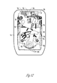
- FIG. 12 is a rear elevation view of the front housing showing the lock assembly in an unlocked position.
- FIG. 13 is a rear elevation view of the front housing showing the lock assembly in a locked position.
- FIGS. 14 and 15 are perspective views from the rear of the front housing.
- FIG. 16 is a partially exploded view of the front housing and a lock module.
- FIG. 17 is a sectional view taken along lines 17 - 17 of FIG. 10 .
- FIG. 18 is a perspective view of the latch module.
- FIGS. 19 and 20 are end elevation views of the latch module taken from opposite ends, and with the rotor being in a closed or latched position.
- FIG. 21 is a side elevation view of the latch module, with the rotor being in a closed or latched position.
- FIG. 22 is a rear plan view of the latch module.
- FIG. 23 is a front plan view of the latch module.
- FIG. 24 is a view similar to FIG. 19 with the front plate removed to show the rotor and catch of the latch module in a latched condition.
- FIG. 25 is a view similar to 24 showing the rotor and catch in an unlatched condition.
- FIG. 26 is an exploded view of the latch module.
- FIGS. 27-29 are perspective views of the mounting bracket according to one embodiment of the invention for remote control or power actuation of the lock mechanism.
- FIG. 30 is a plan view of the interior of the mounting bracket shown in FIGS. 27-34 .
- FIG. 31 is a bottom plan view of the mounting racket.
- FIGS. 32 and 33 are end elevation views of the mounting bracket from opposite ends.
- FIG. 34 is a side elevation view from one side of the mounting bracket.
- FIG. 35 is an exploded perspective view of the mounting racket and associated components.
- the handle assembly of the present invention is generally designated by the reference numeral 10 in the drawings.
- This handle assembly 10 is intended for use on compartment doors on various types of vehicles, such as service truck bodies, RV motor homes, agricultural equipment, construction equipment, and other trucks.
- the handle assembly 10 is mounted in the compartment door in any convenient manner.
- the handle assembly 10 generally includes a front or outer housing 12 and a rear mounting box or bracket 14 .
- the front housing 12 has a plurality of rearwardly extending legs 16 which align with bosses 18 . Screws (not shown) extend forwardly through counter bore holes 19 in the back wall 20 of the mounting bracket 14 for receipt in the legs 16 , thereby securing the front or outer housing 12 to the mounting box or bracket 14 .
- a sealing gasket 13 is provided between the housing 12 and the outer skin of the door to keep our moisture, dust and other contaminants.
- the housing 12 has a recess or well 22 in which an actuation paddle 24 is pivotally mounted. More particularly, the paddle 24 includes a pair of spaced apart legs 26 for receiving an elongated axle 28 .
- the axle extends through opposite side walls of the well 22 , as best seen in FIG. 18 .
- One end of the axle 28 has an enlarged head 30
- the tail or opposite end 32 of the axle 28 has an annular slot 34 .
- the handle assembly 10 also includes a latch module 36 which is mounted to the front housing 12 as a single piece unit.
- the latch module 36 includes a mounting bracket 38 having a central body portion 40 , a mounting flange 42 , and an axle retention flange 44 .
- the flanges 42 , 44 extend substantially perpendicular to the upper body portion 40 .
- the mounting flange 42 has opposite ends with barbs 46 which are adapted to be press fit into channels 48 on the back of the housing 12 for retaining the latch module 36 on the housing 12 .
- the axle flange 44 includes a slot 50 to receive the annular groove 34 of the axle 28 , and thereby retains the axle 38 in the housing 12 .
- the latch module 36 further includes a rotor 52 and a catch 54 which are pivotally mounted upon axles 56 , 58 , respectively.
- the axles 56 , 58 are supported by a front plate 60 .
- a pair of torsion springs 62 , 64 are mounted on the axles 56 , 58 , respectively with one end of each spring being retained by the mounting bracket 38 .
- the opposite ends of the springs 62 , 64 engage the rotor 52 and the catch 54 , respectively, so as to bias the rotor and the catch to an unlatched position, as shown in FIG. 25 .
- the torsion spring 62 biases the rotor 52 to the unlatched position, while the torsion spring 64 biases the catch 54 to the latched position.
- the latch module 36 also includes an actuation plate or cam 66 pivotally mounted on the upper body portion 40 of the mounting bracket 38 via a rivet 68 .
- the cam 66 includes a finger 70 for engaging the catch 54 .
- the latch module 36 includes an extension spring 76 extending between the mounting flange 42 of the mounting bracket 38 and the cam 66 so as to bias the cam to a neutral position wherein the finger 70 is disengaged from the catch 54 .
- the cam 66 also includes a flange 72 on the opposite side of the rivet 68 from the finger 70 which is adapted to be engaged by a leg 74 on the paddle 24 which extends through a slot in the front housing 12 .
- the handle assembly includes a lock assembly 78 .
- the lock assembly comprises an escutcheon 80 mounted in the front housing 12 , a key cylinder 82 mounted in the escutcheon 80 , an actuator 84 connected to the cylinder 82 on the rear or inner end of the escutcheon 80 , and a lock arm or cam 86 mounted to the actuator 84 .
- the escutcheon 80 includes an annular groove 88 for snap fit receipt of a plurality of tabs 90 on the housing 12 , as shown in FIGS. 8, 10, 11 and 13 .
- the lock cam 86 is pivotal between a locked position and an unlocked position.
- the cam end 92 is spaced apart from the latch cam 66 , such that the latch cam is free to pivot upon actuation of the paddle 24 , thereby allowing the rotor 52 and catch 54 of the latch module 36 to move from the latched position to the unlatched position.
- the lock arm 86 is pivoted to the lock position by actuation of the key cylinder 82 and actuator 84 , the end 92 of the cam 86 engages the latch cam 66 to preclude movement of the cam 66 , and thereby preclude the rotor 52 and catch 54 from opening from the latched position to the unlatched position.
- a spring 94 biases the lock cam 86 toward the unlocked position.
- the lock assembly 78 also includes a security or anti-theft plate 96 mounted on the back of the housing 12 so as to reside between the housing 12 and the lock cam 86 .
- the security plate 96 has holes through which the escutcheon 80 and housing legs 16 extend, as well as other structural components on the back of the housing 12 .
- the mounting bracket 14 of the handle assembly 10 may include several optional features which provide enhancements beyond the mounting function of the bracket 14 .
- One option is a latch positioning sensor or switch 100 mounted on a support or holder 101 to the bracket 14 in a position adjacent the rotor 52 .
- the rotor 52 includes an extension 98 which engages or activates the sensor 100 when the rotor is in the latched position, and disengages or deactivates the sensor 100 when the rotor 52 is in the unlatched position.
- the sensor 102 may be electrically coupled to one or more LEDs 102 mounted within the bracket 14 such that the LED is illuminated to indicate locking and unlocking of the handle assembly 10 .
- the LED also provides indication when door is unlatched and power locking event occurs.
- the bracket 14 may also be upgraded for powered operation of the latch module 36 by a remote key fob or other access system user interface.
- This upgrade includes a reversible electric motor 104 mounted inside the bracket 14 .
- the motor output shaft 105 is operatively connected to a rotatable gear 106 in the bracket 14 by a series of gears 110 , 112 , 114 , 115 , and 116 .
- the gears 114 - 116 are mounted between a spacer 118 and a dust cover 120 .
- Shafts 122 , 124 , 125 and 126 rotatably support the gears 112 - 116 , respectively.
- the gear 106 meshes with a plurality of teeth 108 on the lock cam 86 .
- the motor 104 when a receiver connected to the motor 104 receives a signal from the remote transmitter, the motor 104 is actuated to rotate the gear 106 , which in turn pivots the lock cam 86 to the locked or unlocked position.
- the motor 104 or receiver can be electrically coupled to the LEDs 102 mounted in the bracket 14 , with the LEDs indicating when handle assembly 10 is locked and or unlocked.
- a lens 128 can be mounted in the front housing 12 above the LEDs 102 for a person to easily see the latched/unlatched and locked/unlocked condition of the handle assembly 10 .
- a connector plug receiver 130 is ultrasonically welded to the bracket for receiving an electrical plug (not shown).
Abstract
Description
Claims (22)
Priority Applications (1)
| Application Number | Priority Date | Filing Date | Title |
|---|---|---|---|
| US13/097,748 US9399879B2 (en) | 2011-04-29 | 2011-04-29 | Vehicle compartment door handle assembly |
Applications Claiming Priority (1)
| Application Number | Priority Date | Filing Date | Title |
|---|---|---|---|
| US13/097,748 US9399879B2 (en) | 2011-04-29 | 2011-04-29 | Vehicle compartment door handle assembly |
Publications (2)
| Publication Number | Publication Date |
|---|---|
| US20120274457A1 US20120274457A1 (en) | 2012-11-01 |
| US9399879B2 true US9399879B2 (en) | 2016-07-26 |
Family
ID=47067458
Family Applications (1)
| Application Number | Title | Priority Date | Filing Date |
|---|---|---|---|
| US13/097,748 Active 2033-02-23 US9399879B2 (en) | 2011-04-29 | 2011-04-29 | Vehicle compartment door handle assembly |
Country Status (1)
| Country | Link |
|---|---|
| US (1) | US9399879B2 (en) |
Cited By (4)
| Publication number | Priority date | Publication date | Assignee | Title |
|---|---|---|---|---|
| USD837026S1 (en) * | 2016-11-14 | 2019-01-01 | Dassault Aviation | Drawer handle |
| USD837627S1 (en) * | 2016-11-14 | 2019-01-08 | Dassault Aviation | Drawer handle |
| USD850884S1 (en) * | 2016-11-14 | 2019-06-11 | Dassault Aviation | Drawer handle |
| US10815697B1 (en) * | 2017-10-31 | 2020-10-27 | The Eastern Company | Latch apparatus |
Families Citing this family (14)
| Publication number | Priority date | Publication date | Assignee | Title |
|---|---|---|---|---|
| US8881564B2 (en) * | 2012-07-13 | 2014-11-11 | Trimark Corporation | Free floating paddle actuation system |
| US10024085B2 (en) * | 2012-07-13 | 2018-07-17 | Trimark Corporation | Compression mount paddle handle |
| US9127477B1 (en) * | 2012-07-31 | 2015-09-08 | ESSC Group, Inc. | Latch |
| FI124704B (en) * | 2013-04-17 | 2014-12-15 | Rollock Oy | Arrangement for indicating the status of the door lock by means of indicator lights and a cover plate |
| CN103276980B (en) * | 2013-06-09 | 2016-12-28 | 无锡忻润汽车安全系统有限公司 | A kind of vehicle door lock structure of band warning function |
| KR101821243B1 (en) * | 2015-12-28 | 2018-01-24 | 주식회사 우보테크 | Latch system for door of vehicle |
| KR101808548B1 (en) | 2015-12-28 | 2017-12-13 | 주식회사 우보테크 | Latch system for door of vehicle |
| DE102016103423A1 (en) * | 2016-02-26 | 2017-08-31 | Kiekert Ag | Motor vehicle lock |
| DE102016110720A1 (en) * | 2016-06-10 | 2017-12-14 | Huf Hülsbeck & Fürst Gmbh & Co. Kg | Door handle module for a motor vehicle |
| US11692379B2 (en) * | 2018-04-12 | 2023-07-04 | Bauer Products, Inc. | Squeeze trigger latch |
| US11603023B2 (en) * | 2020-02-14 | 2023-03-14 | Waymo Llc | Lockout assembly for folding vehicle seats |
| JP7066064B1 (en) * | 2020-06-01 | 2022-05-12 | 株式会社ジャムコ | Handle attachment and door for lavatory |
| JP7373534B2 (en) * | 2021-09-30 | 2023-11-02 | 本田技研工業株式会社 | Storage box locking mechanism |
| USD995388S1 (en) * | 2022-10-05 | 2023-08-15 | Caterpillar Sarl | Vehicle handle |
Citations (64)
| Publication number | Priority date | Publication date | Assignee | Title |
|---|---|---|---|---|
| US2040258A (en) * | 1934-08-27 | 1936-05-12 | Briggs & Stratton Corp | Mounting means for automobile doorlocks |
| US2610500A (en) * | 1948-07-08 | 1952-09-16 | Illinois Tool Works | Lock retainer |
| US4745250A (en) * | 1987-04-27 | 1988-05-17 | Litton Systems, Inc. | Interlock switch baseplate assembly |
| US4838054A (en) * | 1984-04-18 | 1989-06-13 | The Eastern Company | Latch and lock assemblies with lift and turn handles |
| US4838056A (en) * | 1984-04-18 | 1989-06-13 | The Eastern Company | Latch and lock assemblies with expansible latch elements |
| US4841755A (en) * | 1984-04-18 | 1989-06-27 | The Eastern Company | Latch and lock assemblies with spring-biased slide bolts |
| US4850208A (en) * | 1986-04-28 | 1989-07-25 | The Eastern Company | Latch and lock assemblies with spring-biased pivot bolts |
| US4873852A (en) * | 1987-11-06 | 1989-10-17 | Guy Neyret | Fork for the fixation of a cylinder lock plug |
| US4911487A (en) * | 1986-05-12 | 1990-03-27 | Cleveland Hardware & Forging Co. | Rotary paddle latch |
| US5042853A (en) | 1990-06-06 | 1991-08-27 | Tri-Mark | Paddle latch assembly |
| US5046340A (en) * | 1984-04-18 | 1991-09-10 | The Eastern Company | Latch and lock assemblies with spring-biased pivot bolts |
| US5058258A (en) * | 1990-02-16 | 1991-10-22 | Harvey Steve M | Retrofit electric truck door lock |
| US5119654A (en) * | 1990-12-11 | 1992-06-09 | Euro-Locks, S.A. | Cylinder locks having removable lock barrels |
| US5123691A (en) * | 1991-06-10 | 1992-06-23 | James Ginn | Electric lock apparatus for vehicular tool box |
| US5127686A (en) * | 1991-02-14 | 1992-07-07 | Tri-Mark Corporation | Door closure assembly |
| US5297405A (en) * | 1993-01-25 | 1994-03-29 | General Motors Corporation | Door handle assembly with snap-in key cylinder |
| US5299844A (en) | 1992-10-30 | 1994-04-05 | Tri/Mark Corporation | Sealed latch assembly |
| US5419167A (en) * | 1992-08-17 | 1995-05-30 | Takigen Manufacturing Co., Ltd. | Door grip assembly |
| US5439260A (en) * | 1993-10-29 | 1995-08-08 | The Eastern Company | Handle operable rotary latch and lock |
| US5484178A (en) * | 1994-03-28 | 1996-01-16 | Nyx, Inc. | Side pull latch mechanism |
| US5493881A (en) * | 1993-09-17 | 1996-02-27 | Harvey; Steven M. | Electric door lock for vehicle storage compartments |
| US5586458A (en) * | 1993-10-29 | 1996-12-24 | The Eastern Company | Handle operable rotary latch and lock |
| US5606882A (en) | 1994-09-21 | 1997-03-04 | Tri/Mark Corporation | Lock assembly with interchangeable key plug |
| US5606883A (en) * | 1995-03-23 | 1997-03-04 | Schafer Systems Inc. | Display and dispensing device with lock securing structure |
| US5611224A (en) | 1993-10-29 | 1997-03-18 | The Eastern Company | Handle operable rotary latch and lock |
| US5689980A (en) * | 1996-01-29 | 1997-11-25 | The Eastern Company | Push button lock |
| US5884948A (en) | 1993-10-29 | 1999-03-23 | The Eastern Company | Rotary latch and lock |
| US5941104A (en) | 1997-09-03 | 1999-08-24 | Randall C. Hansen | Paddle lock |
| US5974842A (en) * | 1997-01-08 | 1999-11-02 | Southco, Inc. | Locking slide latch |
| US5983682A (en) * | 1998-11-25 | 1999-11-16 | Cleveland Hardware And Forging Company | Weatherproof paddle latch |
| US5984383A (en) * | 1997-10-17 | 1999-11-16 | Cleveland Hardware And Forging Company | Lockable slammable cam latch with handle key hole cover |
| DE19948677A1 (en) * | 1999-10-08 | 2000-06-08 | Audi Ag | Lock for lid has pulling handle swivel mounted on lid part, with lever part, locking element. support part for pulling-handle, and locking levers. |
| DE19948675A1 (en) * | 1999-10-08 | 2000-06-08 | Audi Ag | Lock for vehicle boot compartment has holder part as locking element swivel mounted on axle, dead center spring, stop over and pulling handle |
| US6116067A (en) * | 1997-11-12 | 2000-09-12 | Fort Lock Corporation | Electronically controlled lock system for tool containers |
| US6393882B1 (en) * | 1999-12-22 | 2002-05-28 | Strattec Security Corporation | Vehicle lock assembly including a mounting bracket |
| US6454321B1 (en) * | 1999-12-23 | 2002-09-24 | Cleveland Hardware And Forging Company | Rotary latch operated by a T-handle with multiple latch actuator connection points |
| US6513353B1 (en) | 1999-01-12 | 2003-02-04 | The Eastern Company | Lockable paddle handle with disconnect feature for operating remotely located latches |
| US6543821B1 (en) * | 2001-04-25 | 2003-04-08 | The Eastern Company | Slam capable latch and lock system |
| US6595033B1 (en) * | 1998-09-02 | 2003-07-22 | Honda Giken Kogyo Kabushiki Kaisha | Attachment structure for key cylinder |
| US6604393B2 (en) * | 2001-07-11 | 2003-08-12 | Tri/Mark Corporation | Lock system operable with multiple keys |
| US6651467B1 (en) | 2000-10-11 | 2003-11-25 | The Eastern Company | T-handle operable rotary latch and lock |
| US20040017087A1 (en) * | 2002-07-24 | 2004-01-29 | Shawn Ayres | Latch apparatus |
| US6708537B1 (en) * | 2002-10-09 | 2004-03-23 | Tri/Mark Corporation | Door lock assembly with free floating paddle |
| US6805388B1 (en) | 2002-04-19 | 2004-10-19 | Tri/Mark Corporation | Door handle pin retainer |
| US6973810B2 (en) * | 2003-06-02 | 2005-12-13 | Ryadon, Inc. | Toolbox rotary latch |
| US20060001276A1 (en) * | 2004-06-30 | 2006-01-05 | Fabrice Vitry | Load-floor latch |
| US7010946B2 (en) * | 2003-05-19 | 2006-03-14 | Truth Hardware Corporation | Latch apparatus |
| US7232162B2 (en) | 2004-07-06 | 2007-06-19 | Trimark Corporation | Composite door lock plunger |
| US7234329B2 (en) * | 2004-03-29 | 2007-06-26 | Tri/Mark Corporation | Lock system for movable closure element |
| US7333021B2 (en) * | 2004-06-24 | 2008-02-19 | Aisin Seiki Kabushiki Kaisha | Opening/closing apparatus for vehicle door |
| US20080157546A1 (en) * | 2004-06-30 | 2008-07-03 | Southco, Inc. | Load-Floor Latch |
| US20080258867A1 (en) * | 2007-04-17 | 2008-10-23 | Cade Harris | Recreational vehicle wireless keyless power door lock |
| US7497488B2 (en) * | 2006-02-28 | 2009-03-03 | Ryadon, Inc | Rotary latch |
| US7611173B2 (en) | 2006-07-18 | 2009-11-03 | Tri/Mark Corporation | Latch system kit and method of making a latch system |
| US7681424B2 (en) * | 2006-04-16 | 2010-03-23 | Southco, Inc. | Swing handle latch |
| US7690142B2 (en) * | 2005-11-23 | 2010-04-06 | Pollack Ronald M | Note holder |
| US7748246B1 (en) * | 2005-03-14 | 2010-07-06 | The Eastern Company | Handle and housing assembly |
| US7819440B2 (en) | 2007-01-31 | 2010-10-26 | Tri/Mark Corporation | Power locking handle for a movable closure element |
| US20100300162A1 (en) * | 2009-06-01 | 2010-12-02 | Cappuccio Louis W | Remote control cam locking system |
| US8146394B2 (en) * | 2009-03-03 | 2012-04-03 | Questek Manufacturing Corporation | Rotary lock actuator |
| US8186191B2 (en) * | 2009-11-30 | 2012-05-29 | Bauer Products, Inc. | Remotely operated locking paddle handle latch assembly for closures and the like |
| US8347667B2 (en) * | 2008-12-22 | 2013-01-08 | Bauer Products, Inc. | Locking paddle handle latch assembly for closures and the like |
| US8393187B2 (en) * | 2008-12-22 | 2013-03-12 | Bauer Products, Inc. | Remotely operated locking paddle handle latch assembly |
| US9127477B1 (en) * | 2012-07-31 | 2015-09-08 | ESSC Group, Inc. | Latch |
-
2011
- 2011-04-29 US US13/097,748 patent/US9399879B2/en active Active
Patent Citations (68)
| Publication number | Priority date | Publication date | Assignee | Title |
|---|---|---|---|---|
| US2040258A (en) * | 1934-08-27 | 1936-05-12 | Briggs & Stratton Corp | Mounting means for automobile doorlocks |
| US2610500A (en) * | 1948-07-08 | 1952-09-16 | Illinois Tool Works | Lock retainer |
| US5046340A (en) * | 1984-04-18 | 1991-09-10 | The Eastern Company | Latch and lock assemblies with spring-biased pivot bolts |
| US4838054A (en) * | 1984-04-18 | 1989-06-13 | The Eastern Company | Latch and lock assemblies with lift and turn handles |
| US4838056A (en) * | 1984-04-18 | 1989-06-13 | The Eastern Company | Latch and lock assemblies with expansible latch elements |
| US4841755A (en) * | 1984-04-18 | 1989-06-27 | The Eastern Company | Latch and lock assemblies with spring-biased slide bolts |
| US4969916A (en) * | 1984-04-18 | 1990-11-13 | The Eastern Company | Latch and lock assemblies with spring-biased pivot bolts |
| US4850208A (en) * | 1986-04-28 | 1989-07-25 | The Eastern Company | Latch and lock assemblies with spring-biased pivot bolts |
| US4850209A (en) * | 1986-04-28 | 1989-07-25 | The Eastern Company | Latch and lock housings, handles and mounting brackets |
| US4911487A (en) * | 1986-05-12 | 1990-03-27 | Cleveland Hardware & Forging Co. | Rotary paddle latch |
| US4745250A (en) * | 1987-04-27 | 1988-05-17 | Litton Systems, Inc. | Interlock switch baseplate assembly |
| US4873852A (en) * | 1987-11-06 | 1989-10-17 | Guy Neyret | Fork for the fixation of a cylinder lock plug |
| US5058258A (en) * | 1990-02-16 | 1991-10-22 | Harvey Steve M | Retrofit electric truck door lock |
| US5042853A (en) | 1990-06-06 | 1991-08-27 | Tri-Mark | Paddle latch assembly |
| US5119654A (en) * | 1990-12-11 | 1992-06-09 | Euro-Locks, S.A. | Cylinder locks having removable lock barrels |
| US5127686A (en) * | 1991-02-14 | 1992-07-07 | Tri-Mark Corporation | Door closure assembly |
| US5123691A (en) * | 1991-06-10 | 1992-06-23 | James Ginn | Electric lock apparatus for vehicular tool box |
| US5419167A (en) * | 1992-08-17 | 1995-05-30 | Takigen Manufacturing Co., Ltd. | Door grip assembly |
| US5299844A (en) | 1992-10-30 | 1994-04-05 | Tri/Mark Corporation | Sealed latch assembly |
| US5297405A (en) * | 1993-01-25 | 1994-03-29 | General Motors Corporation | Door handle assembly with snap-in key cylinder |
| US5493881A (en) * | 1993-09-17 | 1996-02-27 | Harvey; Steven M. | Electric door lock for vehicle storage compartments |
| US5611224A (en) | 1993-10-29 | 1997-03-18 | The Eastern Company | Handle operable rotary latch and lock |
| US5884948A (en) | 1993-10-29 | 1999-03-23 | The Eastern Company | Rotary latch and lock |
| US5564295A (en) * | 1993-10-29 | 1996-10-15 | The Eastern Company | Handle operable rotary latch and lock |
| US5586458A (en) * | 1993-10-29 | 1996-12-24 | The Eastern Company | Handle operable rotary latch and lock |
| US5439260A (en) * | 1993-10-29 | 1995-08-08 | The Eastern Company | Handle operable rotary latch and lock |
| US5484178A (en) * | 1994-03-28 | 1996-01-16 | Nyx, Inc. | Side pull latch mechanism |
| US5606882A (en) | 1994-09-21 | 1997-03-04 | Tri/Mark Corporation | Lock assembly with interchangeable key plug |
| US5606883A (en) * | 1995-03-23 | 1997-03-04 | Schafer Systems Inc. | Display and dispensing device with lock securing structure |
| US5689980A (en) * | 1996-01-29 | 1997-11-25 | The Eastern Company | Push button lock |
| US5974842A (en) * | 1997-01-08 | 1999-11-02 | Southco, Inc. | Locking slide latch |
| US5941104A (en) | 1997-09-03 | 1999-08-24 | Randall C. Hansen | Paddle lock |
| US5984383A (en) * | 1997-10-17 | 1999-11-16 | Cleveland Hardware And Forging Company | Lockable slammable cam latch with handle key hole cover |
| US6116067A (en) * | 1997-11-12 | 2000-09-12 | Fort Lock Corporation | Electronically controlled lock system for tool containers |
| US6595033B1 (en) * | 1998-09-02 | 2003-07-22 | Honda Giken Kogyo Kabushiki Kaisha | Attachment structure for key cylinder |
| US5983682A (en) * | 1998-11-25 | 1999-11-16 | Cleveland Hardware And Forging Company | Weatherproof paddle latch |
| US6513353B1 (en) | 1999-01-12 | 2003-02-04 | The Eastern Company | Lockable paddle handle with disconnect feature for operating remotely located latches |
| DE19948677A1 (en) * | 1999-10-08 | 2000-06-08 | Audi Ag | Lock for lid has pulling handle swivel mounted on lid part, with lever part, locking element. support part for pulling-handle, and locking levers. |
| DE19948675A1 (en) * | 1999-10-08 | 2000-06-08 | Audi Ag | Lock for vehicle boot compartment has holder part as locking element swivel mounted on axle, dead center spring, stop over and pulling handle |
| US6393882B1 (en) * | 1999-12-22 | 2002-05-28 | Strattec Security Corporation | Vehicle lock assembly including a mounting bracket |
| US6454321B1 (en) * | 1999-12-23 | 2002-09-24 | Cleveland Hardware And Forging Company | Rotary latch operated by a T-handle with multiple latch actuator connection points |
| US6651467B1 (en) | 2000-10-11 | 2003-11-25 | The Eastern Company | T-handle operable rotary latch and lock |
| US6543821B1 (en) * | 2001-04-25 | 2003-04-08 | The Eastern Company | Slam capable latch and lock system |
| US6604393B2 (en) * | 2001-07-11 | 2003-08-12 | Tri/Mark Corporation | Lock system operable with multiple keys |
| US6805388B1 (en) | 2002-04-19 | 2004-10-19 | Tri/Mark Corporation | Door handle pin retainer |
| US20040017087A1 (en) * | 2002-07-24 | 2004-01-29 | Shawn Ayres | Latch apparatus |
| US6708537B1 (en) * | 2002-10-09 | 2004-03-23 | Tri/Mark Corporation | Door lock assembly with free floating paddle |
| US7010946B2 (en) * | 2003-05-19 | 2006-03-14 | Truth Hardware Corporation | Latch apparatus |
| US6973810B2 (en) * | 2003-06-02 | 2005-12-13 | Ryadon, Inc. | Toolbox rotary latch |
| US7234329B2 (en) * | 2004-03-29 | 2007-06-26 | Tri/Mark Corporation | Lock system for movable closure element |
| US7333021B2 (en) * | 2004-06-24 | 2008-02-19 | Aisin Seiki Kabushiki Kaisha | Opening/closing apparatus for vehicle door |
| US20060001276A1 (en) * | 2004-06-30 | 2006-01-05 | Fabrice Vitry | Load-floor latch |
| US20080157546A1 (en) * | 2004-06-30 | 2008-07-03 | Southco, Inc. | Load-Floor Latch |
| US7232162B2 (en) | 2004-07-06 | 2007-06-19 | Trimark Corporation | Composite door lock plunger |
| US7748246B1 (en) * | 2005-03-14 | 2010-07-06 | The Eastern Company | Handle and housing assembly |
| US7690142B2 (en) * | 2005-11-23 | 2010-04-06 | Pollack Ronald M | Note holder |
| US7497488B2 (en) * | 2006-02-28 | 2009-03-03 | Ryadon, Inc | Rotary latch |
| US7681424B2 (en) * | 2006-04-16 | 2010-03-23 | Southco, Inc. | Swing handle latch |
| US7861563B2 (en) * | 2006-04-16 | 2011-01-04 | Southco, Inc. | Dual locking system and latch incorporating therefor |
| US7611173B2 (en) | 2006-07-18 | 2009-11-03 | Tri/Mark Corporation | Latch system kit and method of making a latch system |
| US7819440B2 (en) | 2007-01-31 | 2010-10-26 | Tri/Mark Corporation | Power locking handle for a movable closure element |
| US20080258867A1 (en) * | 2007-04-17 | 2008-10-23 | Cade Harris | Recreational vehicle wireless keyless power door lock |
| US8347667B2 (en) * | 2008-12-22 | 2013-01-08 | Bauer Products, Inc. | Locking paddle handle latch assembly for closures and the like |
| US8393187B2 (en) * | 2008-12-22 | 2013-03-12 | Bauer Products, Inc. | Remotely operated locking paddle handle latch assembly |
| US8146394B2 (en) * | 2009-03-03 | 2012-04-03 | Questek Manufacturing Corporation | Rotary lock actuator |
| US20100300162A1 (en) * | 2009-06-01 | 2010-12-02 | Cappuccio Louis W | Remote control cam locking system |
| US8186191B2 (en) * | 2009-11-30 | 2012-05-29 | Bauer Products, Inc. | Remotely operated locking paddle handle latch assembly for closures and the like |
| US9127477B1 (en) * | 2012-07-31 | 2015-09-08 | ESSC Group, Inc. | Latch |
Non-Patent Citations (1)
| Title |
|---|
| Hansen International, www.hansenint.com, Electrified Latch brochure, 2 pages. |
Cited By (4)
| Publication number | Priority date | Publication date | Assignee | Title |
|---|---|---|---|---|
| USD837026S1 (en) * | 2016-11-14 | 2019-01-01 | Dassault Aviation | Drawer handle |
| USD837627S1 (en) * | 2016-11-14 | 2019-01-08 | Dassault Aviation | Drawer handle |
| USD850884S1 (en) * | 2016-11-14 | 2019-06-11 | Dassault Aviation | Drawer handle |
| US10815697B1 (en) * | 2017-10-31 | 2020-10-27 | The Eastern Company | Latch apparatus |
Also Published As
| Publication number | Publication date |
|---|---|
| US20120274457A1 (en) | 2012-11-01 |
Similar Documents
| Publication | Publication Date | Title |
|---|---|---|
| US9399879B2 (en) | Vehicle compartment door handle assembly | |
| US10337221B2 (en) | Slam latch for tool box | |
| KR101193334B1 (en) | Power release double-locking latch | |
| KR101217432B1 (en) | global Side Door Latch | |
| US8903605B2 (en) | System to remotely unlatch a pickup box tailgate | |
| US7516632B2 (en) | Remotely controlled tool box lock apparatus | |
| US6730867B2 (en) | Electrically operated ratcheting pawl latch | |
| JP6726460B2 (en) | Electronic latch release backup system for car doors | |
| WO2014175007A1 (en) | Vehicle door latch control device | |
| US9309701B2 (en) | Slam latch for toolbox | |
| GB2379713A (en) | Latch device for vehicle tailgate | |
| JP2009041219A (en) | Locking device for vehicular change box | |
| JP5734253B2 (en) | Vehicle door lock display energization control device | |
| US10246911B2 (en) | Recreational or utility vehicle door opening system | |
| JP6338921B2 (en) | Door latch device for vehicle | |
| JP2015140614A (en) | Door latch device for vehicle | |
| JP5480100B2 (en) | Door lock device | |
| CN109281555B (en) | Vehicle side door latch apparatus | |
| JP6022312B2 (en) | Door lock device | |
| JP2001262902A (en) | Door lock device for automobile | |
| KR101253312B1 (en) | Electronic Rotary Latch | |
| JP2014095267A (en) | Door lock device | |
| US20240141705A1 (en) | Electro-Mechanically Locking Compression Latch | |
| KR200433858Y1 (en) | Digital door lock | |
| JP2001248347A (en) | Door lock device for car |
Legal Events
| Date | Code | Title | Description |
|---|---|---|---|
| AS | Assignment |
Owner name: TRIMARK CORPORATION, IOWA Free format text: ASSIGNMENT OF ASSIGNORS INTEREST;ASSIGNORS:BURNS, JAYDEN F.;BEARMAN, JENNIFER L.;ROOT, DAVID L.;AND OTHERS;SIGNING DATES FROM 20110721 TO 20110815;REEL/FRAME:026750/0563 |
|
| STCF | Information on status: patent grant |
Free format text: PATENTED CASE |
|
| MAFP | Maintenance fee payment |
Free format text: PAYMENT OF MAINTENANCE FEE, 4TH YR, SMALL ENTITY (ORIGINAL EVENT CODE: M2551); ENTITY STATUS OF PATENT OWNER: SMALL ENTITY Year of fee payment: 4 |
|
| MAFP | Maintenance fee payment |
Free format text: PAYMENT OF MAINTENANCE FEE, 8TH YR, SMALL ENTITY (ORIGINAL EVENT CODE: M2552); ENTITY STATUS OF PATENT OWNER: SMALL ENTITY Year of fee payment: 8 |