US9397961B1 - Method for remapping of allocated memory in queue based switching elements - Google Patents
Method for remapping of allocated memory in queue based switching elements Download PDFInfo
- Publication number
- US9397961B1 US9397961B1 US14/032,557 US201314032557A US9397961B1 US 9397961 B1 US9397961 B1 US 9397961B1 US 201314032557 A US201314032557 A US 201314032557A US 9397961 B1 US9397961 B1 US 9397961B1
- Authority
- US
- United States
- Prior art keywords
- block
- memory
- allocated
- queue
- candidate
- Prior art date
- Legal status (The legal status is an assumption and is not a legal conclusion. Google has not performed a legal analysis and makes no representation as to the accuracy of the status listed.)
- Active, expires
Links
- 238000000034 method Methods 0.000 title claims abstract description 70
- 230000004044 response Effects 0.000 claims abstract description 12
- 238000012544 monitoring process Methods 0.000 claims description 3
- 108091006146 Channels Proteins 0.000 description 41
- 230000009471 action Effects 0.000 description 4
- 230000006870 function Effects 0.000 description 3
- 230000004913 activation Effects 0.000 description 2
- 238000013459 approach Methods 0.000 description 2
- 238000004513 sizing Methods 0.000 description 2
- 230000004075 alteration Effects 0.000 description 1
- 230000008901 benefit Effects 0.000 description 1
- 239000000872 buffer Substances 0.000 description 1
- 230000008859 change Effects 0.000 description 1
- 238000004590 computer program Methods 0.000 description 1
- 230000001419 dependent effect Effects 0.000 description 1
- 238000010586 diagram Methods 0.000 description 1
- 230000000694 effects Effects 0.000 description 1
- 239000004744 fabric Substances 0.000 description 1
- 230000006872 improvement Effects 0.000 description 1
- 238000013507 mapping Methods 0.000 description 1
- 230000007246 mechanism Effects 0.000 description 1
- 230000005012 migration Effects 0.000 description 1
- 238000013508 migration Methods 0.000 description 1
- 238000012986 modification Methods 0.000 description 1
- 230000004048 modification Effects 0.000 description 1
- 230000006855 networking Effects 0.000 description 1
- 230000003287 optical effect Effects 0.000 description 1
- 230000008569 process Effects 0.000 description 1
- 238000012545 processing Methods 0.000 description 1
Images


Classifications
-
- H—ELECTRICITY
- H04—ELECTRIC COMMUNICATION TECHNIQUE
- H04L—TRANSMISSION OF DIGITAL INFORMATION, e.g. TELEGRAPHIC COMMUNICATION
- H04L49/00—Packet switching elements
- H04L49/90—Buffering arrangements
- H04L49/9005—Buffering arrangements using dynamic buffer space allocation
-
- H—ELECTRICITY
- H04—ELECTRIC COMMUNICATION TECHNIQUE
- H04L—TRANSMISSION OF DIGITAL INFORMATION, e.g. TELEGRAPHIC COMMUNICATION
- H04L49/00—Packet switching elements
- H04L49/30—Peripheral units, e.g. input or output ports
-
- H—ELECTRICITY
- H04—ELECTRIC COMMUNICATION TECHNIQUE
- H04L—TRANSMISSION OF DIGITAL INFORMATION, e.g. TELEGRAPHIC COMMUNICATION
- H04L49/00—Packet switching elements
- H04L49/30—Peripheral units, e.g. input or output ports
- H04L49/3036—Shared queuing
-
- H—ELECTRICITY
- H04—ELECTRIC COMMUNICATION TECHNIQUE
- H04L—TRANSMISSION OF DIGITAL INFORMATION, e.g. TELEGRAPHIC COMMUNICATION
- H04L49/00—Packet switching elements
- H04L49/90—Buffering arrangements
- H04L49/901—Buffering arrangements using storage descriptor, e.g. read or write pointers
Definitions
- the present disclosure relates to data networking applications, including but not limited to switch fabrics, network switch elements, packet buffers, storage queues, dynamic memory allocation and memory management.
- Switching elements have the ability to receive data from multiple sources and to transmit such data to multiple destinations.
- Each source communicates to a switching element through an ingress interface (also called ingress port on the switching element).
- a switching element transmits data to each destination by driving its egress interface (also called egress port).
- FIG. 1 illustrates a switching element having 4 ingress ports and 4 egress ports. Certain types of switching elements are referred to as fully-connected switches while others are referred to as partially-connected switches.
- a fully-connected switch such as illustrated in FIG. 1 , can direct data from any ingress port to any egress port.
- Each path or connection from ingress port to egress port can be referred to as a “port pair”.
- a switching element with 4 ingress and 4 egress ports will have a total of 16 possible port pairs.
- FIG. 1 also illustrates the port pair connections of a fully connected switching element having 4 ingress ports and 4 egress ports.
- a data source connected to a single ingress port can generate multiple unique streams of data. Each stream of data can be tagged with a channel number by the source.
- a channelized switching element can direct individual channels on an ingress port to a particular channel of an egress port. This is similar to sending data with a source address and a destination address.
- FIG. 2 illustrates a switching element with active channels driving ingress ports, queue elements that store data in transit to an egress channel of an egress port. Most switching elements are required to store received data until the data is transmitted to the egress ports. The received data is typically stored in queues within the switching element, as shown in FIG. 2 . Because the data is channelized, each channel of data requires a queue. For example: a switching element with 4 ingress, 4 egress ports, and each ingress and egress port supports 128 channels. The switching element will contain 16*128 individual queues (one queue per channel, per port pair).
- each queue can be referred to as a queue element.
- Each of the queue elements requires a predetermined amount of storage, or memory, for holding the channel data while in transit from ingress to egress port.
- the amount of storage a queue element requires is dependent on the characteristics of the data stream. Therefore, not all queue elements require the same amount of storage.
- Many methods of allocating storage to queue elements are known. One method includes providing dedicated storage for each queue element, while other methods share storage across all the queue elements. For shared storage methods, storage is allocated and de-allocated dynamically as needed. Some methods of dynamic storage allocation allocate memory when a channel is activated (also called provisioning a channel), and de-allocate memory when a channel is de-activated (also called de-provisioning a channel). More complex methods of dynamic storage allocation allocate memory when data arrives at a particular queue and then de-allocate storage as the data exits the queue and is transmitted to the egress port.
- each port pair with one or more active channels must be allocated at least one physical memory element.
- a port pair with a newly activated channel, and no channel currently active on the port pair needs a completely empty and dedicated physical memory element, such as a random access memory (RAM) in order to be allocated.
- RAM random access memory
- memory elements cannot be shared between port pairs, as individual memory elements, also called pages, are allocated to individual port pairs; and b) a block of memory cannot be shared between queues, as individual blocks are allocated to individual queues.
- a switching element with 16 active port pairs must therefore include a minimum of 16 physical memory elements.
- An active port pair is defined as a port pair with one or more active channels. The storage available within a memory element is shared either dynamically or statically amongst the queue elements of the port pair. In some examples a switching element with 16 port pairs may have only 1 active channel on a single port pair; depending on the traffic profile of that channel the queue element servicing the channel could require multiple memory elements.
- the smallest amount of storage that can be allocated to a queue is typically called a block of memory, or simply a block.
- a memory element there are multiple blocks of memory available for allocation to queue elements.
- a single memory element, such as a RAM, is referred to as a page of memory.
- the total amount of memory available for all queue elements is equal to the number of pages and these pages are made of blocks.
- FIG. 3 illustrates a switch element with 16 memory elements, each port pair having 1 memory element allocated thereto.
- every port pair could support an active channel.
- the maximum number of channels that could be supported for each port pair is equal to the number of blocks within each individual memory element.
- FIG. 4 illustrates a switch element with 16 memory elements in which a single port pair is allocated all available memory elements.
- only port pair 3 - 3 (ingress-egress port) could support an active channel.
- the maximum number of channels that could be supported for port pair 3 - 3 is equal to the total number of blocks within all memory elements.
- switching elements In switching elements with dynamic memory allocation, when no channels are active, every block of memory is unallocated and therefore every page of memory is also unallocated.
- the switching element which could be hardware or software controlled, allocates a memory element to the port pair and also allocates a block within that memory element to the queue element servicing the channel.
- One method to track allocated blocks is via a block allocation table.
- the block allocation table tracks the allocated blocks, the memory element allocation to a port pair, the association of a block to a queue element and the logical order of the block within the queue element.
- the block allocation table can be maintained by software or hardware.
- Channels activated on an already active port pair can be allocated blocks of memory from an already allocated memory element. When no blocks are available within the already allocated memory element, because they are taken by other queue elements, the switching element must allocate a new memory element to the port pair. As channels are de-activated, the switching element must de-allocate the blocks of memory. Once all blocks of a memory element have been de-allocated, the switching element can de-allocate the memory element itself, making it available to other port pairs.
- This repeated process of channel activation and de-activation can cause the range of available memory to become sparsely allocated, or partially allocated.
- allocated blocks of memory are non-contiguous, which can leave a port pair with more than 1 memory element allocated but with only a few blocks allocated in each memory element.
- Some switching elements also support re-sizing of queues as the data stream characteristics change. The re-sizing of queues, combined with channel activation and de-activation, can also result in the available memory becoming sparsely allocated, or fragmented.
- a block of memory in the memory element is further allocated to a channel on the port pair, or to a queue servicing the channel.
- FIG. 1 illustrates a switching element having 4 ingress ports and 4 egress ports.
- FIG. 2 illustrates a switching element with active channels driving ingress ports, queue elements that store data in transit to an egress channel of an egress port.
- FIG. 3 illustrates a switch element with 16 memory elements, each port pair having 1 memory element allocated thereto.
- FIG. 4 illustrates a switch element with 16 memory elements in which a single port pair is allocated all available memory elements.
- FIG. 5 illustrates a sparsely allocated memory and an associated block allocation table.
- FIG. 6 illustrates a method of remapping allocated memory according to an embodiment of the present disclosure.
- FIG. 8 illustrates an example embodiment of a second step in a method of remapping allocated memory according to an embodiment of the present disclosure.
- FIG. 9 illustrates an example in which read and write pointers are in a suitable position for remapping.
- FIG. 10 illustrates an example in which read and write pointers are in an unsuitable position for remapping.
- FIG. 11 illustrates a guard band example in which read and write pointers are in a suitable position for remapping.
- FIG. 12 illustrates a guard band example in which read and write pointers are in an unsuitable position for remapping.
- FIG. 13 illustrates an example embodiment of a fourth step in a method of remapping allocated memory according to an embodiment of the present disclosure.
- a method of remapping allocated memory in a queue based switching element having first and second memory elements each allocated to a first port pair An unallocated block of memory is identified in the first memory element as a candidate block, and an allocated block of memory is identified in the second memory element as a target block. Block information is copied from the target block to the candidate block, and the candidate block is maintained as unallocated.
- the candidate block is allocated and the target block is deallocated so that the second memory element becomes unallocated and available for reallocation to a second port pair.
- Embodiments of the present disclosure relate to a method to remap, or re-allocate, blocks of memory.
- a method remaps blocks of memory without interrupting the flow of data through the queue and also without corrupting the data.
- blocks are mapped to a new location within the existing memory element or to a new memory element. This makes it possible to migrate allocated blocks from one memory element to another, thus potentially freeing up memory elements and resolving fragmented memory allocation.
- the method operates on any block within a queue element irrespective of the logical position of the block being targeted for remap.
- the present disclosure provides a method of remapping allocated memory in a queue-based switching element having ingress ports and egress ports. Each path or connection from a selected ingress port to a selected egress port defines a port pair.
- the queue-based switching element comprises first and second memory elements.
- the method comprises: identifying an unallocated block of memory in the first memory element as a candidate block, the candidate block being a candidate for allocation, the first memory element being allocated to a first port pair and being associated with a first logical block number; identifying an allocated block of memory in the second memory element as a target block, the target block being a target for deallocation, the second memory element being allocated to the first port pair and being associated with the first logical block number; copying block information from the target block to the candidate block and maintaining the candidate block as unallocated; and in response to a determination that read and write pointers associated with the first logical block number are in a suitable position for a remapping operation, allocating the candidate block and deallocating the target block so that the second memory element becomes unallocated and available for reallocation to a second port pair.
- allocating the candidate block and deallocating the target block are performed in response to a determination that the read and write pointers are in a suitable position for the remapping operation to complete without affecting contents of a queue associated with the first logical block number.
- the method further comprises: monitoring read and write pointers to determine whether the read and write pointers are in a suitable position for the remapping operation to complete. In an example embodiment, the method further comprises providing an indication that the read and write pointers are in a suitable position for the remapping operation to complete.
- the method further comprises determining that the pointers are in the suitable position when: the write pointer is about to advance into the target block; and the read pointer is not within the target block.
- the method further comprises determining that the pointers are in the suitable position when: the write pointer is about to enter the guard band region; and the read pointer is neither within the target block, nor within the guard band region.
- the method further comprises reallocating the second memory element to the second port pair.
- copying the block information comprises copying a port pair identifier, a queue number and a logical block number.
- the allocated block of memory in the second memory element is a channel-allocated block of memory, allocated to a particular channel of the first port pair.
- the candidate block prior to the step of copying, is free of queue entries and the target block comprises at least one queue entry.
- the present disclosure provides a non-transitory machine readable medium having stored thereon statements and instructions for execution by a processor to perform a method of remapping allocated memory in a queue-based switching element as described and illustrated herein.
- the present disclosure provides a method of remapping allocated memory in a queue-based switching element having ingress ports and egress ports, each path or connection from a selected ingress port to a selected egress port defining a port pair, the method comprising: identifying an unallocated block of memory as a candidate block, the candidate block being a candidate for allocation; identifying an allocated block of memory as a target block, the target block being a target for deallocation, the candidate block and the target block each being allocated to a first port pair and being associated with a first logical block number; copying block information from the target block to the candidate block and maintaining the candidate block as unallocated; and in response to a determination that read and write pointers associated with the first logical block number are in a suitable position for a remapping operation, allocating the candidate block and deallocating the target block to enable reallocation of a memory element to a second port pair.
- FIG. 5 illustrates a sparsely allocated memory and an associated block allocation table.
- the RAM 0 and RAM 1 are each allocated to port pair 2 - 1 , with 2 blocks allocated from RAM 0 and 1 block allocated from RAM 1 .
- the 3 allocated blocks shown in FIG. 5 are made to reside within a single memory element, so as to free up a memory element, making it available to other port pairs.
- a method functions as follows.
- a currently allocated physical block of memory is selected as the “target” block for remapping, and a new physical block of memory is selected as the “candidate” block.
- FIG. 6 illustrates a method of remapping allocated memory according to an embodiment of the present disclosure.
- the method may include more or fewer steps than indicated.
- many of the steps or actions are performed by queue element logic.
- some steps or actions are performed by the queue element logic, and other steps or actions are performed by memory management hardware/software.
- the example embodiment of FIG. 6 is a method of remapping allocated memory in a queue-based switching element having ingress ports and egress ports. Each path or connection from a selected ingress port to a selected egress port defines a port pair, and the queue-based switching element comprises first and second memory elements.
- An initial step comprises identifying an unallocated block of memory in the first memory element as a candidate block.
- the candidate block is a candidate for allocation and can be free of queue entries.
- the first memory element is allocated to a first port pair and associated with a first logical block number.
- a next step comprises identifying an allocated block of memory in the second memory element as a target block.
- the target block is a target for deallocation and comprises at least one queue entry.
- the second memory element is allocated to the same first port pair and associated with the same logical block number as the first memory element.
- the allocated block of memory is a channel-allocated block of memory, allocated to a particular channel of the first port pair, or to a queue element servicing the channel.
- a further step comprises copying block information from the target block to the candidate block and maintaining the candidate block as unallocated.
- the block information can comprise the port pair identifier, the queue number and the logical block number of the target block.
- the candidate block is free of queue entries and the target block comprises at least one queue entry.
- the second memory element comprises allocated blocks of memory and unallocated blocks of memory.
- a subsequent step comprises, in response to a determination that read and write pointers associated with the first logical block number are in a suitable position for a remapping operation, allocating the candidate block and deallocating the target block so that the second memory element becomes unallocated and available for reallocation to a second port pair.
- allocating the candidate block comprises marking the candidate block as allocated
- deallocating the target block comprises marking the target block as unallocated.
- the method comprises determining that the read and write pointers are in a suitable position for the remapping operation, as will be described in further detail in the following examples.
- the method comprises: identifying an unallocated block of memory as a candidate block, the candidate block being a candidate for allocation; identifying an allocated block of memory as a target block, the target block being a target for deallocation, the candidate block and the target block each being allocated to a first port pair and being associated with a first logical block number; copying block information from the target block to the candidate block and maintaining the candidate block as unallocated; and in response to a determination that read and write pointers associated with the first logical block number are in a suitable position for a remapping operation, allocating the candidate block and deallocating the target block to enable reallocation of a memory element to a second port pair.
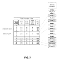
- FIGS. 7-13 illustrate the effects on a block allocation table and on memory elements of steps or actions in a method according to an embodiment of the present disclosure.
- the method comprises four steps.
- step 1 is performed by the memory management software
- step 3 is performed by the queue element control logic
- step 2 involves sending information from the memory management hardware/software to the queue element control logic
- step 4 involves sending information from the queue element control logic to the memory management hardware/software.
- the 1st step of the method is to select a candidate and target block.
- the target block is already allocated and marked as “allocated” in the block allocation table.
- the target block entry in the block allocation table is already programmed with the “port pair”, “queue number” and the “logical block number”. Since the candidate block will be taking the place of the target block, the candidate block entry of the block mapping table is programmed with the same values as the target block for the “port pair”, “queue number” and “logical block number”. For example, the “port pair”, “queue number” and “logical block number” values are copied from the target block to the candidate block, but the candidate block remains inactive.
- FIG. 7 illustrates an example embodiment of the 1st step where block 5 from memory element 1 is selected as the target block, and block 2 from memory element 0 is selected as the candidate block.
- Block 5 is currently associated to port pair 2 - 1 , queue number 0 , and logical block 1 .
- the candidate block table entry is programmed identically with port pair 2 - 1 , queue number 0 , and logical block 1 .
- the candidate block remains marked as “not allocated”, while the target block remains marked as “allocated”.
- the 2nd step of the method is to forward the logical block number for the target and candidate to the queue element control logic.
- FIG. 8 illustrates an example embodiment of the 2nd step where logical block 1 is the target block. This particular queue element 0 , has 3 blocks currently allocated to it. Each block can store 4 entries.
- the 3 rd step of the method is for the queue element logic to monitor the queue read and write pointers and to provide an indication that the pointers are in a suitable position for the remap operation to complete so as to not affect the contents of the queue.
- the method operates while the queue is servicing data (active traffic).
- the write pointer When a queue receives data, the write pointer will advance.
- the read pointer When a queue forwards data to a destination, the read pointer will advance.
- the queue logic determines that the pointers are in a suitable position whenever the following 2 conditions are met: 1) the write pointer is about to advance into the target block, e.g. position 3; and 2) the read pointer is not within the target block. This guarantees that no currently active data are stored within the target block while the remap function is being performed.
- the pointers can move before the remap operation is complete.
- the queue logic determines that the pointers are in a suitable position whenever the following 2 conditions are met: 1) the write pointer is about to enter the guard band region and 2) the read pointer is not within the target block, nor the guard band region. This guarantees that no currently active data are stored within the target block while the remap function is being performed.
- FIG. 9 illustrates an example in which read and write pointers are in a suitable position for remapping.
- the write pointer is on location 3 , the last entry of logical block 0 and is advancing to location 4 the first entry of the target block, logical block 1 .
- the read pointer is on location 8 , just outside of the target block memory range.
- FIG. 10 illustrates an example in which read and write pointers are in an unsuitable position for the remapping to occur.
- FIG. 11 illustrates a guard band example in which read and write pointers are in a suitable position for remapping.
- FIG. 12 illustrates a guard band example in which read and write pointers are in an unsuitable position for remapping.
- the 4th step of the method is for the queue logic to signal that the pointers are in a suitable position and for the block allocation table to be updated.
- the target physical block is marked as “not allocated” and the candidate physical block is marked as “allocated”.
- FIG. 13 illustrates an example embodiment of a 4th step where block 5 from memory element 1 was selected as the target block, and block 2 from memory element 0 was selected as the candidate block.
- the queue logic has signaled that the pointers are in a suitable position, this has caused the block 5 to be marked as “not allocated” and block 2 to be marked as “allocated”.
- the figure shows that memory element 1 is now unallocated and available for a different port as needed.
- the logical blocks of queue 0 , port pair 2 - 1 are all packed within memory element 0 .
- the method further comprises reallocating memory element 1 to a different port pair.
- Embodiments of the present disclosure enable remapping of any block to any other block while traffic is being processed. Steps in a method according to an embodiment of the present disclosure are performed by the queue element logic. In another embodiment, some steps are performed by the queue element logic, and some are performed by the associated memory management software or memory management hardware.
- Embodiments of the present disclosure are tied to port pair memory sharing, and to freeing up a memory element so that it is available for a port pair.
- memory can become fragmented such that pages are only partially allocated (i.e.: unallocated blocks present in page). Freeing up the partially allocated pages is important as other port pairs may require additional blocks, and memory can be fragmented such that no pages are free. Being able to hitlessly remap a logical block from one physical block address to a new physical block address allows the migration of blocks from one page to another. When all blocks have been moved away from a Page, that Page can be re-allocated to a different port pair.
- queue element logic has an input port, and can receive a logical block number and a request to perform a remap.
- the queue element logic receives the logical block number for the target from the block allocation table, and it can respond back indicating the right time to do the remap.
- an embedded processor running on a chip generates the request to perform a remap, or it could be on the network and controlling it from afar.
- the memory management software referred to herein is the same memory management software used to provision and deprovision channels.
- a method facilitates remapping, from a second memory element to a first memory element, blocks allocated to a first port pair, so that the allocated blocks of the first port pair all reside within the first memory element, freeing up and unallocating the second memory element, making it available for reallocation to a second port pair.
- Embodiments of the disclosure can be represented as a computer program product stored in a machine-readable medium (also referred to as a computer-readable medium, a processor-readable medium, or a computer usable medium having a computer-readable program code embodied therein).
- the machine-readable medium can be any suitable tangible, non-transitory medium, including magnetic, optical, or electrical storage medium including a diskette, compact disk read only memory (CD-ROM), memory device (volatile or non-volatile), or similar storage mechanism.
- the machine-readable medium can contain various sets of instructions, code sequences, configuration information, or other data, which, when executed, cause a processor to perform steps in a method according to an embodiment of the disclosure.
Abstract
Description
Claims (21)
Priority Applications (1)
| Application Number | Priority Date | Filing Date | Title |
|---|---|---|---|
| US14/032,557 US9397961B1 (en) | 2012-09-21 | 2013-09-20 | Method for remapping of allocated memory in queue based switching elements |
Applications Claiming Priority (2)
| Application Number | Priority Date | Filing Date | Title |
|---|---|---|---|
| US201261704396P | 2012-09-21 | 2012-09-21 | |
| US14/032,557 US9397961B1 (en) | 2012-09-21 | 2013-09-20 | Method for remapping of allocated memory in queue based switching elements |
Publications (1)
| Publication Number | Publication Date |
|---|---|
| US9397961B1 true US9397961B1 (en) | 2016-07-19 |
Family
ID=56381798
Family Applications (1)
| Application Number | Title | Priority Date | Filing Date |
|---|---|---|---|
| US14/032,557 Active 2034-07-25 US9397961B1 (en) | 2012-09-21 | 2013-09-20 | Method for remapping of allocated memory in queue based switching elements |
Country Status (1)
| Country | Link |
|---|---|
| US (1) | US9397961B1 (en) |
Cited By (7)
| Publication number | Priority date | Publication date | Assignee | Title |
|---|---|---|---|---|
| US20180048543A1 (en) * | 2014-01-27 | 2018-02-15 | Keysight Technologies Singapore (Holdings) Pte. Ltd. | Traffic Differentiator Systems And Related Methods Including Automatic Packet Stream Order Determination |
| WO2019199817A1 (en) * | 2018-04-12 | 2019-10-17 | Advanced Micro Devices, Inc. | Queue in a network switch |
| US11294678B2 (en) | 2018-05-29 | 2022-04-05 | Advanced Micro Devices, Inc. | Scheduler queue assignment |
| US11334384B2 (en) * | 2019-12-10 | 2022-05-17 | Advanced Micro Devices, Inc. | Scheduler queue assignment burst mode |
| US11722406B2 (en) * | 2019-12-13 | 2023-08-08 | Hewlett Packard Enterprise Development Lp | Route selection based on buffer congestion |
| US11892955B2 (en) | 2021-06-01 | 2024-02-06 | Microchip Technology Inc. | System and method for bypass memory read request detection |
| US11948000B2 (en) | 2020-10-27 | 2024-04-02 | Advanced Micro Devices, Inc. | Gang scheduling for low-latency task synchronization |
Citations (10)
| Publication number | Priority date | Publication date | Assignee | Title |
|---|---|---|---|---|
| US6076112A (en) * | 1995-07-19 | 2000-06-13 | Fujitsu Network Communications, Inc. | Prioritized access to shared buffers |
| US20020075882A1 (en) * | 1998-05-07 | 2002-06-20 | Marc Donis | Multiple priority buffering in a computer network |
| EP1720295A1 (en) | 2005-05-02 | 2006-11-08 | Broadcom Corporation | Dynamic sharing of a transaction queue |
| US20060292292A1 (en) * | 1998-05-08 | 2006-12-28 | Brightman Thomas B | Digital communications processor |
| US7397815B2 (en) | 2005-01-27 | 2008-07-08 | Lucent Technologies Inc. | Method and apparatus for performing link defragmentation subject to an interface rate constraint |
| US20080270676A1 (en) * | 2005-01-31 | 2008-10-30 | Nxp B.V. | Data Processing System and Method for Memory Defragmentation |
| US20080279207A1 (en) * | 2007-05-11 | 2008-11-13 | Verizon Services Organization Inc. | Method and apparatus for improving performance in a network using a virtual queue and a switched poisson process traffic model |
| US20080301256A1 (en) * | 2007-05-30 | 2008-12-04 | Mcwilliams Thomas M | System including a fine-grained memory and a less-fine-grained memory |
| US8255644B2 (en) | 2009-05-18 | 2012-08-28 | Lsi Corporation | Network communications processor architecture with memory load balancing |
| US20130315054A1 (en) * | 2012-05-24 | 2013-11-28 | Marvell World Trade Ltd. | Flexible queues in a network switch |
-
2013
- 2013-09-20 US US14/032,557 patent/US9397961B1/en active Active
Patent Citations (10)
| Publication number | Priority date | Publication date | Assignee | Title |
|---|---|---|---|---|
| US6076112A (en) * | 1995-07-19 | 2000-06-13 | Fujitsu Network Communications, Inc. | Prioritized access to shared buffers |
| US20020075882A1 (en) * | 1998-05-07 | 2002-06-20 | Marc Donis | Multiple priority buffering in a computer network |
| US20060292292A1 (en) * | 1998-05-08 | 2006-12-28 | Brightman Thomas B | Digital communications processor |
| US7397815B2 (en) | 2005-01-27 | 2008-07-08 | Lucent Technologies Inc. | Method and apparatus for performing link defragmentation subject to an interface rate constraint |
| US20080270676A1 (en) * | 2005-01-31 | 2008-10-30 | Nxp B.V. | Data Processing System and Method for Memory Defragmentation |
| EP1720295A1 (en) | 2005-05-02 | 2006-11-08 | Broadcom Corporation | Dynamic sharing of a transaction queue |
| US20080279207A1 (en) * | 2007-05-11 | 2008-11-13 | Verizon Services Organization Inc. | Method and apparatus for improving performance in a network using a virtual queue and a switched poisson process traffic model |
| US20080301256A1 (en) * | 2007-05-30 | 2008-12-04 | Mcwilliams Thomas M | System including a fine-grained memory and a less-fine-grained memory |
| US8255644B2 (en) | 2009-05-18 | 2012-08-28 | Lsi Corporation | Network communications processor architecture with memory load balancing |
| US20130315054A1 (en) * | 2012-05-24 | 2013-11-28 | Marvell World Trade Ltd. | Flexible queues in a network switch |
Cited By (9)
| Publication number | Priority date | Publication date | Assignee | Title |
|---|---|---|---|---|
| US20180048543A1 (en) * | 2014-01-27 | 2018-02-15 | Keysight Technologies Singapore (Holdings) Pte. Ltd. | Traffic Differentiator Systems And Related Methods Including Automatic Packet Stream Order Determination |
| US10680917B2 (en) * | 2014-01-27 | 2020-06-09 | Keysight Technologies Singapore (Sales) Pte. Ltd. | Traffic differentiator systems and related methods including automatic packet stream order determination |
| WO2019199817A1 (en) * | 2018-04-12 | 2019-10-17 | Advanced Micro Devices, Inc. | Queue in a network switch |
| US10601723B2 (en) | 2018-04-12 | 2020-03-24 | Advanced Micro Devices, Inc. | Bandwidth matched scheduler |
| US11294678B2 (en) | 2018-05-29 | 2022-04-05 | Advanced Micro Devices, Inc. | Scheduler queue assignment |
| US11334384B2 (en) * | 2019-12-10 | 2022-05-17 | Advanced Micro Devices, Inc. | Scheduler queue assignment burst mode |
| US11722406B2 (en) * | 2019-12-13 | 2023-08-08 | Hewlett Packard Enterprise Development Lp | Route selection based on buffer congestion |
| US11948000B2 (en) | 2020-10-27 | 2024-04-02 | Advanced Micro Devices, Inc. | Gang scheduling for low-latency task synchronization |
| US11892955B2 (en) | 2021-06-01 | 2024-02-06 | Microchip Technology Inc. | System and method for bypass memory read request detection |
Similar Documents
| Publication | Publication Date | Title |
|---|---|---|
| US9397961B1 (en) | Method for remapping of allocated memory in queue based switching elements | |
| US20190179660A1 (en) | Vm-aware ftl design for sr-iov nvme ssd | |
| US10198215B2 (en) | System and method for multi-stream data write | |
| KR20100077156A (en) | Thin provisioning migration and scrubbing | |
| KR20170083963A (en) | Array controller, solid state disk, and method for controlling solid state disk to write data | |
| US20170075614A1 (en) | Memory system and host apparatus | |
| CN111159061A (en) | Storage device, operation method of storage device, and operation method of host controlling storage device | |
| KR20180127176A (en) | Namespace/Stream Management | |
| US11681628B2 (en) | Managing memory allocation between input/output adapter caches | |
| US9063841B1 (en) | External memory management in a network device | |
| JP2016170703A (en) | Storage device, control method of storage device and information processing system | |
| JP6231899B2 (en) | Semiconductor device, processor system, and control method thereof | |
| US9529745B2 (en) | System on chip and method of operating a system on chip | |
| US20090254729A1 (en) | Method of wear leveling for a non-volatile memory | |
| JP2020154827A (en) | Memory apparatus and control method for memory apparatus | |
| CN106598696B (en) | Method and device for data interaction between virtual machines | |
| EP3166019B1 (en) | Memory devices and methods | |
| US20200371708A1 (en) | Queueing Systems | |
| CN114442910A (en) | Method, electronic device and computer program product for managing storage system | |
| EP3474147A1 (en) | Cache management method and device, and computer storage medium | |
| CN111124253A (en) | Method, apparatus and computer program product for managing storage devices | |
| CN110581869B (en) | Resource allocation method, TLP packet processing method, equipment and storage medium | |
| US10254961B2 (en) | Dynamic load based memory tag management | |
| US20120082017A1 (en) | Storage region providing device, storage region providing method, and recording medium | |
| KR20150095978A (en) | Distributed Storage System using Local Disk of Computing Node on Cloud Computing |
Legal Events
| Date | Code | Title | Description |
|---|---|---|---|
| AS | Assignment |
Owner name: PMC-SIERRA US, INC., CALIFORNIA Free format text: ASSIGNMENT OF ASSIGNORS INTEREST;ASSIGNOR:BAILEY, PATRICK NEIL;REEL/FRAME:031249/0928 Effective date: 20130919 |
|
| FEPP | Fee payment procedure |
Free format text: PAYER NUMBER DE-ASSIGNED (ORIGINAL EVENT CODE: RMPN); ENTITY STATUS OF PATENT OWNER: LARGE ENTITY Free format text: PAYOR NUMBER ASSIGNED (ORIGINAL EVENT CODE: ASPN); ENTITY STATUS OF PATENT OWNER: LARGE ENTITY |
|
| AS | Assignment |
Owner name: MORGAN STANLEY SENIOR FUNDING, INC., NEW YORK Free format text: PATENT SECURITY AGREEMENT;ASSIGNORS:MICROSEMI STORAGE SOLUTIONS, INC. (F/K/A PMC-SIERRA, INC.);MICROSEMI STORAGE SOLUTIONS (U.S.), INC. (F/K/A PMC-SIERRA US, INC.);REEL/FRAME:037689/0719 Effective date: 20160115 |
|
| AS | Assignment |
Owner name: MICROSEMI STORAGE SOLUTIONS (U.S.), INC., CALIFORN Free format text: CHANGE OF NAME;ASSIGNOR:PMC-SIERRA US, INC.;REEL/FRAME:038213/0291 Effective date: 20160115 |
|
| STCF | Information on status: patent grant |
Free format text: PATENTED CASE |
|
| AS | Assignment |
Owner name: MICROSEMI SOLUTIONS (U.S.), INC., CALIFORNIA Free format text: CHANGE OF NAME;ASSIGNOR:MICROSEMI STORAGE SOLUTIONS (U.S.), INC.;REEL/FRAME:042836/0046 Effective date: 20170109 |
|
| AS | Assignment |
Owner name: MICROSEMI STORAGE SOLUTIONS (U.S.), INC., CALIFORN Free format text: RELEASE BY SECURED PARTY;ASSIGNOR:MORGAN STANLEY SENIOR FUNDING, INC.;REEL/FRAME:046251/0271 Effective date: 20180529 Owner name: MICROSEMI STORAGE SOLUTIONS, INC., CALIFORNIA Free format text: RELEASE BY SECURED PARTY;ASSIGNOR:MORGAN STANLEY SENIOR FUNDING, INC.;REEL/FRAME:046251/0271 Effective date: 20180529 |
|
| MAFP | Maintenance fee payment |
Free format text: PAYMENT OF MAINTENANCE FEE, 4TH YEAR, LARGE ENTITY (ORIGINAL EVENT CODE: M1551); ENTITY STATUS OF PATENT OWNER: LARGE ENTITY Year of fee payment: 4 |
|
| MAFP | Maintenance fee payment |
Free format text: PAYMENT OF MAINTENANCE FEE, 8TH YEAR, LARGE ENTITY (ORIGINAL EVENT CODE: M1552); ENTITY STATUS OF PATENT OWNER: LARGE ENTITY Year of fee payment: 8 |