US9337767B2 - Single bus star connected reluctance drive and method - Google Patents
Single bus star connected reluctance drive and method Download PDFInfo
- Publication number
- US9337767B2 US9337767B2 US14/318,170 US201414318170A US9337767B2 US 9337767 B2 US9337767 B2 US 9337767B2 US 201414318170 A US201414318170 A US 201414318170A US 9337767 B2 US9337767 B2 US 9337767B2
- Authority
- US
- United States
- Prior art keywords
- phase
- phases
- current
- preemptive
- angle
- Prior art date
- Legal status (The legal status is an assumption and is not a legal conclusion. Google has not performed a legal analysis and makes no representation as to the accuracy of the status listed.)
- Active, expires
Links
- 238000000034 method Methods 0.000 title claims abstract description 59
- 238000007599 discharging Methods 0.000 claims description 13
- 230000003247 decreasing effect Effects 0.000 claims description 3
- 230000008569 process Effects 0.000 abstract description 32
- 239000012071 phase Substances 0.000 description 235
- 238000012360 testing method Methods 0.000 description 11
- 238000004590 computer program Methods 0.000 description 7
- 238000010586 diagram Methods 0.000 description 7
- 230000006870 function Effects 0.000 description 7
- 239000003990 capacitor Substances 0.000 description 5
- 238000004519 manufacturing process Methods 0.000 description 5
- 230000003287 optical effect Effects 0.000 description 3
- 238000004891 communication Methods 0.000 description 2
- 230000007423 decrease Effects 0.000 description 2
- 230000005284 excitation Effects 0.000 description 2
- 239000013307 optical fiber Substances 0.000 description 2
- 238000012545 processing Methods 0.000 description 2
- 230000000644 propagated effect Effects 0.000 description 2
- 239000004065 semiconductor Substances 0.000 description 2
- 239000012072 active phase Substances 0.000 description 1
- 238000013459 approach Methods 0.000 description 1
- 230000008901 benefit Effects 0.000 description 1
- 230000001413 cellular effect Effects 0.000 description 1
- 238000001816 cooling Methods 0.000 description 1
- 238000005265 energy consumption Methods 0.000 description 1
- 230000006872 improvement Effects 0.000 description 1
- 230000010354 integration Effects 0.000 description 1
- 239000010977 jade Substances 0.000 description 1
- 238000012423 maintenance Methods 0.000 description 1
- 239000000463 material Substances 0.000 description 1
- 230000007246 mechanism Effects 0.000 description 1
- 238000012986 modification Methods 0.000 description 1
- 230000004048 modification Effects 0.000 description 1
- 230000007935 neutral effect Effects 0.000 description 1
- 230000009022 nonlinear effect Effects 0.000 description 1
- 230000010363 phase shift Effects 0.000 description 1
- 229910052761 rare earth metal Inorganic materials 0.000 description 1
- 150000002910 rare earth metals Chemical class 0.000 description 1
- 238000012358 sourcing Methods 0.000 description 1
- 230000001360 synchronised effect Effects 0.000 description 1
- 230000009466 transformation Effects 0.000 description 1
- 230000000007 visual effect Effects 0.000 description 1
Images


Classifications
-
- H—ELECTRICITY
- H02—GENERATION; CONVERSION OR DISTRIBUTION OF ELECTRIC POWER
- H02P—CONTROL OR REGULATION OF ELECTRIC MOTORS, ELECTRIC GENERATORS OR DYNAMO-ELECTRIC CONVERTERS; CONTROLLING TRANSFORMERS, REACTORS OR CHOKE COILS
- H02P25/00—Arrangements or methods for the control of AC motors characterised by the kind of AC motor or by structural details
- H02P25/02—Arrangements or methods for the control of AC motors characterised by the kind of AC motor or by structural details characterised by the kind of motor
- H02P25/08—Reluctance motors
- H02P25/086—Commutation
-
- H—ELECTRICITY
- H02—GENERATION; CONVERSION OR DISTRIBUTION OF ELECTRIC POWER
- H02P—CONTROL OR REGULATION OF ELECTRIC MOTORS, ELECTRIC GENERATORS OR DYNAMO-ELECTRIC CONVERTERS; CONTROLLING TRANSFORMERS, REACTORS OR CHOKE COILS
- H02P25/00—Arrangements or methods for the control of AC motors characterised by the kind of AC motor or by structural details
- H02P25/02—Arrangements or methods for the control of AC motors characterised by the kind of AC motor or by structural details characterised by the kind of motor
- H02P25/08—Reluctance motors
- H02P25/092—Converters specially adapted for controlling reluctance motors
-
- H02P25/085—
-
- H—ELECTRICITY
- H02—GENERATION; CONVERSION OR DISTRIBUTION OF ELECTRIC POWER
- H02P—CONTROL OR REGULATION OF ELECTRIC MOTORS, ELECTRIC GENERATORS OR DYNAMO-ELECTRIC CONVERTERS; CONTROLLING TRANSFORMERS, REACTORS OR CHOKE COILS
- H02P25/00—Arrangements or methods for the control of AC motors characterised by the kind of AC motor or by structural details
- H02P25/02—Arrangements or methods for the control of AC motors characterised by the kind of AC motor or by structural details characterised by the kind of motor
- H02P25/08—Reluctance motors
- H02P25/092—Converters specially adapted for controlling reluctance motors
- H02P25/0925—Converters specially adapted for controlling reluctance motors wherein the converter comprises only one switch per phase
Definitions
- the present invention relates to switched reluctance and variable reluctance machines.
- the present invention relates to a control method and drive system for switched reluctance and variable reluctance machines.
- Transportation systems are an integral part of an industrial society. By providing mobility, transportation systems enable the trading of goods and convenience for users. These systems require energy to operate. The increase in population has resulted in more energy consumption by transportation systems. The cause for a cleaner environment and conservation of energy sources has led to the integration of more electric vehicles in the transportation systems. This has been accomplished by introducing hybrid electric vehicles and electric vehicles.
- Switched reluctance machines have high torque densities, which can provide a solution for replacing permanent magnet machines.
- drives of the prior art for switched reluctance machines having n number of phases have a high number of semiconductor switches which will increase the cost of the converter dramatically.
- the drives of the prior art require a high number of cable connections to the switched reluctance machines, which is a drawback for automotive applications of switched reluctance machines.
- asymmetric bridge 101 of the prior art is shown.
- This topology requires 2 ⁇ n switches and 2 ⁇ n diodes for an n-phase switched reluctance machine.
- soft-switching inverters have been utilized in high speed applications where the switching frequency of the inverter is high.
- 2 ⁇ n lead wires are required.
- the number of wires is an important factor because of the increased cost of manufacturing and maintenance per added wire. Therefore, the use of asymmetric bridges in automotive applications increases the costs of manufacturing.
- C-dump inverter 102 of the prior art is shown.
- Star connection 103 connects to buck converter 104 to provide a secondary voltage source for the operation of the drive.
- Dump capacitor 105 is the input capacitor for buck converter 104 .
- Dump capacitor 105 is used for dumping the magnetizing energy of each phase at the end of the corresponding conduction cycle.
- C-dump inverter 102 requires n+1 switches and n+1 diodes for a switched reluctance machine having n phases.
- C-dump inverter 102 requires dump capacitor 105 or a variable voltage structure to maintain operational conditions.
- dump capacitor 105 is bulky and requires cooling for operating at high temperatures. Therefore, the use of C-dump inverter 102 in automotive applications is costly and an inefficient use of space.
- a method for controlling a switched reluctance machine includes the steps of determining a conduction band for an electrical phase angle for each phase of a set of phases, enforcing a reference current in each phase of the set of phases, determining a preemptive band for the electrical phase angle for each phase of the set of phases, increasing the reference current to a preemptive reference current in each phase of the set of phases, and discharging the reference current from each phase of the set of phases.
- a method for controlling a switched reluctance machine includes the steps of determining a conduction band for an electrical phase angle for each phase of a set of phases, increasing a first current in each phase of the set of phases, determining a reference current for the first current in each phase of the set of phases, enforcing the reference current on each phase of the set of phases, determining a preemptive band for the electrical phase angle for each phase of the set of phases, reducing the reference current to a preemptive current in each phase of the set of phases, and discharging the reference current from each phase of the set of phases.
- a system for operating a switched reluctance machine includes a controller, an inverter connected to the controller and to the switched reluctance machine, a hysteresis control connected to the controller and to the inverter, a set of sensors connected to the switched reluctance machine and to the controller, the switched reluctance machine further including a set of phases, the controller further including a processor and a memory connected to the processor, wherein the processor programmed to execute a control process and a generation process.
- FIG. 1A is a schematic of an asymmetric bridge of the prior art.
- FIG. 1B is a schematic of a C-dump inverter of the prior art.
- FIG. 2A is a block diagram of a preferred embodiment.
- FIG. 2B is a schematic of an inverter of a preferred embodiment.
- FIG. 2C is a schematic of an inverter in a hard chopping mode of a preferred embodiment.
- FIG. 2D is a schematic of an inverter in a hard chopping mode of a preferred embodiment.
- FIG. 2E is a schematic of an inverter in a soft chopping mode of a preferred embodiment.
- FIG. 2F is a schematic of an inverter in a soft chopping mode of a preferred embodiment.
- FIG. 3 is a graph of an inductance profile and a corresponding drive current for a multi-phase switched reluctance machine of a preferred embodiment.
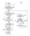
- FIG. 4A is a flowchart of a method for controlling a drive of a switched reluctance machine of a preferred embodiment.
- FIG. 4B is a graph of phase currents versus rotor position of a preferred embodiment.
- FIG. 5 is a flowchart of a method for controlling a drive of a switched reluctance machine of a preferred embodiment.
- FIG. 6 is a graph of measured voltage and current waveforms of a phase of a switched reluctance machine of a preferred embodiment.
- FIG. 7 is a graph of measured current waveforms for multiple phases of a switched reluctance machine of a preferred embodiment.
- FIG. 8 is a graph of measured current waveforms for multiple phases of a switched reluctance machine during a single pulse generation mode of the prior art.
- FIG. 9 is a graph of measured current waveforms for multiple phases of a switched reluctance machine of a preferred embodiment.
- aspects of the present disclosure may be illustrated and described herein in any of a number of patentable classes or context including any new and useful process, machine, manufacture, or composition of matter, or any new and useful improvement thereof. Therefore, aspects of the present disclosure may be implemented entirely in hardware, entirely in software (including firmware, resident software, micro-code, etc.) or combining software and hardware implementation that may all generally be referred to herein as a “circuit,” “module,” “component,” or “system.” Further, aspects of the present disclosure may take the form of a computer program product embodied in one or more computer readable media having computer readable program code embodied thereon.
- the computer readable media may be a computer readable signal medium or a computer readable storage medium.
- a computer readable storage medium may be, but not limited to, an electronic, magnetic, optical, electromagnetic, or semiconductor system, apparatus, or device, or any suitable combination of the foregoing.
- a computer readable storage medium may be any tangible medium that can contain, or store a program for use by or in connection with an instruction execution system, apparatus, or device.
- a computer readable signal medium may include a propagated data signal with computer readable program code embodied therein, for example, in baseband or as part of a carrier wave.
- the propagated data signal may take any of a variety of forms, including, but not limited to, electro-magnetic, optical, or any suitable combination thereof.
- a computer readable signal medium may be any computer readable medium that is not a computer readable storage medium and that can communicate, propagate, or transport a program for use by or in connection with an instruction execution system, apparatus, or device.
- Program code embodied on a computer readable signal medium may be transmitted using any appropriate medium, including but not limited to wireless, wireline, optical fiber cable, RF, or any suitable combination thereof.
- Computer program code for carrying out operations for aspects of the present disclosure may be written in any combination of one or more programming languages, including an object oriented programming language such as Java, Scala, Smalltalk, Eiffel, JADE, Emerald, C++, C#, VB.NET, Python or the like, conventional procedural programming languages, such as the “C” programming language, Visual Basic, Fortran 2003, Perl, COBOL 2002, PHP, ABAP, dynamic programming languages such as Python, Ruby and Groovy, or other programming languages.
- object oriented programming language such as Java, Scala, Smalltalk, Eiffel, JADE, Emerald, C++, C#, VB.NET
- Python or the like
- conventional procedural programming languages such as the “C” programming language, Visual Basic, Fortran 2003, Perl, COBOL 2002, PHP, ABAP, dynamic programming languages such as Python, Ruby and Groovy, or other programming languages.
- These computer program instructions may also be stored in a computer readable medium that when executed can direct a computer, other programmable data processing apparatus, or other devices to function in a particular manner, such that the instructions when stored in the computer readable medium produce an article of manufacture including instructions which when executed, cause a computer to implement the function/act specified in the flowchart and/or block diagram block or blocks.
- the computer program instructions may also be loaded onto a computer, other programmable instruction execution apparatus, or other devices to cause a series of operational steps to be performed on the computer, other programmable apparatuses or other devices to produce a computer implemented process such that the instructions which execute on the computer or other programmable apparatus provide processes for implementing the functions/acts specified in the flowchart and/or block diagram block or blocks.
- supply 201 of system 200 is connected to inverter 204 with main supply line 205 and to controller 202 with auxiliary line 203 .
- Controller 202 is connected to inverter 204 and to hysteresis control 209 .
- Inverter 204 is connected to switched reluctance machine 206 and to hysteresis control 209 .
- Switched reluctance machine 206 is connected to sensors 207 .
- Sensors 207 are connected to controller 202 with feedback line 208 .
- Controller 202 has processor 210 connected to memory 211 . Control processes are stored in memory 211 and are executed by processor 210 .
- Controller 202 is configured with a first set of program instructions which are executed when controller 202 is powered on.
- the first set of program instructions are a set of machine code instructions that receives and examines data of switched reluctance machine 206 from sensors 207 through feedback line 208 , compares the data to pre-determined rules, and switches power on and off to n phases of switched reluctance machine 206 based on the comparisons to operate switched reluctance machine 206 .
- controller 202 sends a signal to inverter 204 to activate each phase of switched reluctance machine 206 and a reference current to hysteresis control 209 for each phase.
- Inverter 204 supplies a current for switched reluctance machine 206 in a motoring mode and receives a current from switched reluctance machine 206 in a generating mode. The motoring mode and the generating mode are further discussed below.
- Hysteresis control 209 receives the reference current, the actual current for each phase of switched reluctance machine 206 , and the phase which is energized by inverter 204 .
- Hysteresis control 209 sends gate signals to inverter 204 to energize a given phase of switched reluctance machine 206 .
- Sensors 207 detect a rotor position, phase voltage, and phase currents from switched reluctance machine 206 .
- switched reluctance machine 206 has n phases, a rotor, and at least one stator. In another embodiment, switched reluctance machine 206 is a variable reluctance machine having n phases. Other switched reluctance machines known in the art may be employed.
- switched reluctance machine 206 operates in a motoring mode generating torque. In another embodiment, switched reluctance machine 206 operates in a generation mode, generating a current back to supply 201 .
- sensors 207 are a set of rotor position, voltage, inductance, and current sensors. Any suitable position, voltage, inductance, or current sensor known in the art may be employed.
- rotor position is detected directly through a mounted rotor position sensor.
- rotor position is calculated using the measured voltage and measured current using a function with a 1 : 1 correspondence with rotor position.
- sensors 207 connect to controller 202 through feedback line 208 .
- sensors 207 connect to controller 202 wirelessly via a Wi-Fi network, a cellular network, a Bluetooth connection, or a ZigBee wireless communication system.
- a Wi-Fi network a Wi-Fi network
- a cellular network a Wi-Fi network
- Bluetooth connection a Wi-Fi connection
- ZigBee wireless communication system a wireless communications means known in the art may be employed.
- hysteresis control 209 is a current loop.
- Other suitable current hysteresis controllers known in the art may be employed.
- inverter 204 is shown. Inverter 204 is a neutral connected asymmetric bridge, a Miller converter. Each of n phases of switched reluctance machine 206 is connected to an asymmetric leg of inverter 204 capable of sinking current and star connected to an asymmetric leg of inverter 204 capable sourcing current.
- Phase a is connected to leg 212 and leg 216 .
- Phase b is connected to leg 213 and leg 216 .
- Phase c is connected to leg 214 and leg 216 .
- Phase n is connected to leg 215 and 216 .
- Leg 216 has switch S c , and diode D c . For a given phase i, leg i has switch S i and diode D i .
- phase i In use, current is increased for a given phase i of n phases of switched reluctance machine 206 by turning on switch S c and switch S i of phase i. A positive v dc is applied to phase i.
- Hard chopping modes for a given phase i is achieved through switches S c and S i or diodes D c and D i pairs. Referring to FIG. 2C , switches S c and S i are turned on to achieve hard chopping on phase i. Referring to FIG. 2D , diodes D c and D i are turned on to achieve hard chopping on phase i.
- a soft chopping mode for a given phase i is achieved by turning on switch S c and diode D i .
- a soft chopping mode for a given phase i is achieved by turning on switch S i and diode D c .
- current is decreased on phase i using soft chopping by applying zero voltage over phase i with back electromotive force (EMF) from switched reluctance machine 206 .
- EMF back electromotive force
- switch S c is turned on and switch S i is turned off, thereby applying the zero voltage across phase i.
- current is decreased on phase i using hard chopping by applying a negative v dc across phase i.
- Switches S c and S i are turned off.
- the current on phase i forces diodes D c and D i to turn on, thereby discharging current on phase i.
- an inductance profile and the corresponding drive current for switched reluctance machine 206 having phases a, b, c, and d is shown.
- ⁇ is the electrical phase angle of the rotor of switched reluctance machine 206 .
- Curve 301 is the inductance for phase a and curve 302 is the current for phase a.
- Curve 303 is the inductance for phase b and curve 304 is the current for phase b.
- Curve 305 is the inductance for phase c and curve 306 is the current for phase c.
- Curve 307 is the inductance for phase d and curve 308 is the current for phase d.
- the conduction band in a motoring mode of operation for a phase is a range of electrical phase angles of the rotor of switched reluctance machine 206 where the inductance increases.
- Each phase has conduction bands approximately 60 degrees apart, thereby conducting approximately six times during a full rotation of the rotor of switched reluctance machine 206 .
- the phase shift of the conduction bands between two adjacent phases is approximately 15 degrees.
- Positive slopes 309 and 310 of curve 301 are conduction bands of phase a.
- Positive slopes 311 and 312 of curve 303 are conduction bands for phase b.
- Positive slopes 313 and 314 of curve 305 are conduction bands for phase c.
- Positive slopes 315 , 316 , and 317 of curve 307 are conduction bands for phase d.
- the conduction bands of phases a, b, c, and d overlap. An overlap of approximately 15 degrees is observed between conduction bands of adjacent phases.
- Each phase has a preemptive band, a range of the electrical phase angles of the rotor of switched reluctance machine 206 wherein the current in the previous phase, i ⁇ 1, is turning off and the current in phase i is turned on.
- motoring control process 400 is described for a given phase i of switched reluctance machine 206 . Control process 400 is repeated for each of n phases of switched reluctance machine 206 .
- processor 210 of controller 202 executes motoring control process 400 stored in memory 211 .
- motoring control process 400 controls switched reluctance machine 206 to generate a torque.
- Motoring control process 400 begins at step 401 as the rotor approaches the conduction band for phase i.
- a starting angle of a conduction band of phase i is determined, i.e., whether the electrical phase angle of the rotor is greater than a predetermined starting electrical phase angle.
- step 402 repeats.
- step 403 an end of the conduction band of phase i is determined, i.e., whether the electrical phase angle of the rotor is greater than a predetermined ending electrical phase angle.
- step 404 hysteresis control 209 enforces a predetermined reference current on phase i by turning on switches S i and S c within the conduction band. Current increases with hard chopping of switches S c and S i . Current decreases with soft chopping of switch S c and diode D i .
- step 405 a preemptive band of the electrical phase angle of the rotor in phase i is determined, i.e., whether the electrical phase angle of the rotor is greater than a starting preemptive angle and less than an ending preemptive angle.
- Each phase has a preemptive band, a range of the electrical phase angles of the rotor of switched reluctance machine 206 wherein the current in the previous phase, i ⁇ 1, is turning off and the current in phase i is turned on. If the electrical phase angle of the rotor is not within the predetermined preemptive band, then step 403 is repeated. In step 406 , if the electrical phase angle of the rotor is within the preemptive band angle range, then the reference current is increased to the preemptive reference current. While switches S i ⁇ 1 and S c are turned off to discharge the current in phase i ⁇ 1, switch S i remains turned on to prevent hard chopping in phase i.
- phase i while phase i ⁇ 1 is turning off, phase i is still conducting.
- curve 411 is the current in phase i
- curve 412 is the current in phase i ⁇ 1.
- Switches S i ⁇ 1 and S c have to be turned off to discharge the current in phase i ⁇ 1.
- switch S i remains turned on resulting in freewheeling of current for phase i through D c , which can reduce the current below the reference current due the back EMF of switched reluctance machine 206 .
- the reference current in phase i is increased to the preemptive reference current.
- the current decreases to the reference current after the preemptive band angle range ends.
- the average current remains unchanged.
- step 407 switches S i and S c are turned off when the electrical phase angle is greater than the ending angle of the conduction band for phase i.
- Switch S i+1 is turned on to enforce soft chopping on phase 1+1.
- step 408 switches S i and S c remain turned off until the reference current in phase i is approximately zero.
- step 409 switches S i+1 and S c are turned on to begin phase i+1.
- Motor control process 400 ends at step 410 .
- generation process 500 is described for a given phase i of switched reluctance machine 206 .
- Generation process 500 is repeated for each of n phases of switched reluctance machine 206 .
- processor 210 of controller 202 executes generation process 500 stored in memory 211 .
- generation process 500 controls switched reluctance machine 206 to generate current.
- Generation process 500 begins at step 501 .
- a starting angle of a conduction band of phase i is determined, i.e., whether the electrical phase angle of the rotor is greater than a predetermined starting electrical phase angle.
- step 502 repeats until the electrical phase angle of the rotor is greater than the predetermined starting electrical phase angle.
- switches S i and S c are turned on and switch S i ⁇ 1 is turned off to enforce soft chopping on phase i ⁇ 1.
- a first current in phase i increases.
- step 504 whether the first current in phase i is approximately equal to a reference current is determined. Step 504 is repeated until the first current in phase i is approximately equal to the reference current.
- step 505 switch S i ⁇ 1 is turned on and switch S c is turned off once the first current in phase i is approximately equal the reference current.
- step 506 a determination is made whether the conduction band of phase i has ended, i.e., whether the electrical phase angle is greater than a predetermined ending electrical phase angle.
- step 507 hysteresis control 209 is applied within the conduction band of phase i to continue enforcing the reference current on phase i.
- Switch S c remains turned off and switch S i remains turned on. Current increases with the soft chopping of switch S i and diode D c using the back EMF of switched reluctance machine 206 .
- a preemptive band of the electrical phase angle of the rotor for generation in phase i is determined, i.e., whether the electrical phase angle of the rotor is greater than a starting preemptive angle and less than an ending preemptive angle. If the electrical phase angle of the rotor is not within the preemptive band, then steps 506 , 507 , and 508 are repeated until the electrical phase angle is within the preemptive band.
- the electrical phase angle is within the preemptive band and the reference current is reduced to the preemptive reference current for generation.
- the preemptive reference current is predetermined for the generation cycle.
- a second current is charging phase i+1 while phase i is conducting.
- Switches S i+1 and S c are turned on to increase the second current of phase i+1.
- Switch S i remains turned on to prevent hard chopping on phase i resulting in soft chopping on phase i, which can increase the first current to greater than the reference current.
- the reference current is reduced to the preemptive reference current.
- step 506 switch S i is turned off in step 510 to discharge the current of phase i using diodes D c and D i for hard chopping. Current is discharged from phase i back to the dc bus.
- Generation process 500 ends at step 511 .
- a model of switched reluctance machine 206 can be used to calculate the preemptive reference currents and to calculate the required time for controller 202 to charge and discharge the phase currents.
- the dynamic equations of switched reluctance machine 206 during multi-phase operation can be calculated using:
- v k R k ⁇ i k + d L kk d ⁇ ⁇ d ⁇ d t ⁇ i k + d L kk d i k ⁇ d i k d t + d i k d t ⁇ L kk + d L kj d ⁇ ⁇ d ⁇ d t ⁇ i j + d L kj d i j ⁇ d i j d t + d i j d t ⁇ L kj Eq .
- Phase j is turned off during the conduction band of phase k. If the rotation speed of the rotor is relatively slow compared to the switching period, the variations of the rotor angle can be neglected. If the nonlinear effects of the core due to the saturation of switched reluctance machine 206 are considered to be very small, then the variations of the inductance with respect to the variations of the current are negligible. Therefore, Eq. 1 can be simplified as:
- v k R k ⁇ i k + d L kk d ⁇ ⁇ ⁇ ⁇ i k + d L kj d ⁇ ⁇ ⁇ ⁇ ⁇ i j + d i k d t ⁇ L kk + d i j d t ⁇ L kj Eq .
- a 12 R j ⁇ L kj + ⁇ ⁇ ( L ⁇ ⁇ ′ jj ⁇ ⁇ L kj - L ⁇ ⁇ ′ kj ⁇ ⁇ L jj ) L kk ⁇ L jj - L jk ⁇ L kj Eq .
- a 21 R k ⁇ L jk + ⁇ ⁇ ( L ⁇ ⁇ ′ kk ⁇ ⁇ L jk - L ⁇ ⁇ ′ jk ⁇ ⁇ L kk ) L kk ⁇ L jj - L jk ⁇ L kj Eq .
- L′ jk ⁇ is the derivative of the inductance with respect to the rotor angle, i.e.,
- phase k 0.
- the phase currents of switched reluctance machine 206 during the discharge of the current from phase j can be calculated as:
- I k ⁇ ( s ) 1 sF 1 ⁇ ( s ) ⁇ ⁇ i pre * ⁇ ( L kk ⁇ L jj - L jk 2 ) ⁇ s 2 + v d ⁇ ⁇ c ⁇ L jk ⁇ ′ ⁇ ⁇ + [ ( L jj ⁇ ′ ⁇ ( i pre * ⁇ ( L kk + i * ⁇ L jk ) - L jk ⁇ ⁇ ′ ⁇ ( i pre * ⁇ L jk + i * ⁇ L jj ) ) ⁇ ⁇ + ( i pre * ⁇ L kk + i * ⁇ L jk ) ⁇ R j + L jk ⁇ v d ⁇ ⁇ c ] ⁇ s ⁇ Eq .
- I j ⁇ ( s ) 1 sF 1 ⁇ ( s ) ⁇ ⁇ i * ⁇ ( L kk ⁇ L jj - L jk 2 ) ⁇ s 2 - v d ⁇ ⁇ c ⁇ ( L kk ⁇ ′ ⁇ ⁇ + R k ) + [ ( L kk ⁇ ′ ⁇ ( i pre * ⁇ ( L jk + i * ⁇ L jj ) - L jk ⁇ ⁇ ′ ⁇ ( i pre * ⁇ L kk + i * ⁇ L jk ) ) ⁇ ⁇ + ( i pre * ⁇ L jk + i * ⁇ L jj ) ⁇ R k - L kk ⁇ v d ⁇ ⁇ c ] ⁇ s ⁇ Eq .
- the initial conditions of the variables are added to the Laplace transform. It can be assumed that the current of phase k has reached the preemptive reference current i pre * and the current of phase j is the reference current i* prior to the discharge cycle.
- the required time for discharging the current can be calculated.
- the required time for discharging the current corresponds to the minimum amount of turn-off angle required for discharging the current before the generation mode starts.
- the required preemptive reference current, i pre *, to keep the average of the current unchanged in the soft chopping phase, phase k can be calculated using Eq. 12.
- the mutual inductances as compared to the self-inductances are small values. Usually, Eq. 12 and Eq. 13 cannot be simplified further. However, if the mutual inductance between phases j and k is neglected, Eq. 12 and Eq. 13 can be simplified as:
- I k ⁇ ( s ) i pre * ⁇ L kk L kk ⁇ s + L ⁇ ⁇ ′ kk ⁇ ⁇ ⁇ + R k Eq . ⁇ 15
- I j ⁇ ( s ) i * ⁇ L jj ⁇ s - v d ⁇ ⁇ c s ⁇ ( L jj ⁇ s + L ⁇ ⁇ ′ jj ⁇ ⁇ ⁇ + R j ) Eq . ⁇ 16 and the currents during the required time for discharging can be calculated using
- the required amount of time to discharge the current and the required preemptive current can be calculated using
- the preemptive reference current can keep the average of the current of phase k constant.
- the required model to calculate the preemptive reference currents is derived.
- the model can be used to calculate the required time necessary for controller 202 to charge and discharge the phase currents.
- Test 1 motoring control process 400 was tested.
- Switched reluctance machine 206 was operating on a multi-phase excitation.
- a reference current of 2.5 A was applied to switched reluctance machine 206 .
- measured voltage waveform 601 and measured current waveform 602 of phase a of switched reluctance machine 206 are shown.
- Reference current 603 is increased to preemptive reference current 604 during the preemptive band of phase a prior to the discharge period of the previous phase, phase d.
- Reference current 603 was set at 2.5 A.
- Preemptive reference current 604 was set at 4.75 A.
- Soft chopping was performed on phase a during the discharge period of phase d.
- the measured current waveforms of each phase of switched reluctance machine 206 are shown synchronized with the measured signals in FIG. 6 controlling switched reluctance machine 206 during motoring control process 400 .
- Current waveform 701 is the measured current in phase a.
- Current waveform 702 is the measured current in phase b.
- Current waveform 703 is the measured current in phase c.
- Current waveform 704 is the measured current in phase d.
- Preemptive reference current 705 was calculated using Eq. 19.
- the overall average current during preemptive band 706 and freewheeling period 707 of phase b is equal to reference current 708 .
- the average current during preemptive band 706 and freewheeling period 707 of phase b is the total area under current waveform 703 .
- Current waveform 801 is the measured current in phase a.
- Current waveform 802 is the measured current in phase b.
- Current waveform 803 is the measured current in phase c.
- Current waveform 804 is the measured current in phase d.
- the phases are magnetized first, then the current is discharged from the phases.
- Single pulse generation of the prior art can include a freewheeling cycle to allow the back EMF to increase the amplitude of the current.
- Reference current 805 was 3 A. After each conduction band, current 806 was 8 A. This current stress from the single pulse generation process of the prior art can lead to failure of the diodes in inverter 204 , thereby requiring higher rating for the diodes of inverter 204 .
- Test 3 generation process 500 was tested. In contrast to Test 2, the controlled and limited peak current amplitudes, the stress over inverter 204 , and the current ratings of the diodes of inverter 204 were reduced.
- Current waveform 901 is the measured current in phase a.
- Current waveform 902 is the measured current in phase b.
- Current waveform 903 is the measured current in phase c.
- Current waveform 904 is the measured current in phase d.
- Reference current 905 was 4 A. The maximum current was limited to 5 A. When the current reaches the maximum current in each phase, hard chopping is performed using generation process 500 to absorb the energy from each phase, thereby restricting the current to the boundaries of hysteresis control 209 .
- preemptive reference current 906 is used. Preemptive reference current 906 is less than reference current 905 .
- preemptive band 908 reduces the current from reference current 905 to preemptive reference current 906 before increasing to the maximum current during freewheeling period 909 .
Abstract
Description
where vk and ik is the voltage and the phase current of phase k of
where L′jk
ik is the derivative of the current with respect to time. During the discharge period, the applied voltage of
where the characteristic function F1(s) can be calculated using:
F 1(S)=(L kk L jj −L jk 2)s 2+[(L′ jj
For this transformation, the initial conditions of the variables are added to the Laplace transform. It can be assumed that the current of phase k has reached the preemptive reference current ipre* and the current of phase j is the reference current i* prior to the discharge cycle.
and the currents during the required time for discharging can be calculated using
The required amount of time to discharge the current and the required preemptive current can be calculated using
During the discharge period of phase j, the preemptive reference current can keep the average of the current of phase k constant. The required model to calculate the preemptive reference currents is derived. The model can be used to calculate the required time necessary for
Claims (20)
Priority Applications (1)
| Application Number | Priority Date | Filing Date | Title |
|---|---|---|---|
| US14/318,170 US9337767B2 (en) | 2013-06-28 | 2014-06-27 | Single bus star connected reluctance drive and method |
Applications Claiming Priority (2)
| Application Number | Priority Date | Filing Date | Title |
|---|---|---|---|
| US201361840957P | 2013-06-28 | 2013-06-28 | |
| US14/318,170 US9337767B2 (en) | 2013-06-28 | 2014-06-27 | Single bus star connected reluctance drive and method |
Publications (2)
| Publication Number | Publication Date |
|---|---|
| US20150002055A1 US20150002055A1 (en) | 2015-01-01 |
| US9337767B2 true US9337767B2 (en) | 2016-05-10 |
Family
ID=52114939
Family Applications (1)
| Application Number | Title | Priority Date | Filing Date |
|---|---|---|---|
| US14/318,170 Active 2034-07-02 US9337767B2 (en) | 2013-06-28 | 2014-06-27 | Single bus star connected reluctance drive and method |
Country Status (1)
| Country | Link |
|---|---|
| US (1) | US9337767B2 (en) |
Families Citing this family (2)
| Publication number | Priority date | Publication date | Assignee | Title |
|---|---|---|---|---|
| CN107872184A (en) * | 2017-11-20 | 2018-04-03 | 常州大学 | A kind of switched reluctance motor controller optimization design |
| CN111525847B (en) * | 2020-05-21 | 2022-02-15 | 华中科技大学 | Magnetic field modulation driving topology of dual-channel switched reluctance motor and control method thereof |
Citations (7)
| Publication number | Priority date | Publication date | Assignee | Title |
|---|---|---|---|---|
| US4961038A (en) * | 1989-10-16 | 1990-10-02 | General Electric Company | Torque estimator for switched reluctance machines |
| US5166591A (en) * | 1991-12-02 | 1992-11-24 | General Electric Company | Current chopping strategy for generating action in switched reluctance machines |
| US5530333A (en) * | 1993-07-20 | 1996-06-25 | Switched Reluctance Drives Limited | Control of an inductive load |
| US5754024A (en) * | 1995-12-26 | 1998-05-19 | Aisin Seiki Kabushiki Kaisha | Control device for switched reluctance motor |
| US6002222A (en) * | 1997-01-24 | 1999-12-14 | Switched Reluctance Drives Limited | Device and method for controlling a time variable inductive load |
| US6366048B2 (en) * | 1999-12-22 | 2002-04-02 | Daimlerchrysler Ag | Method and arrangement for regulating the current in a switched reluctance machine |
| US6661206B2 (en) * | 2001-12-10 | 2003-12-09 | Delphi Technologies, Inc. | Soft chopping for switched reluctance generators |
-
2014
- 2014-06-27 US US14/318,170 patent/US9337767B2/en active Active
Patent Citations (7)
| Publication number | Priority date | Publication date | Assignee | Title |
|---|---|---|---|---|
| US4961038A (en) * | 1989-10-16 | 1990-10-02 | General Electric Company | Torque estimator for switched reluctance machines |
| US5166591A (en) * | 1991-12-02 | 1992-11-24 | General Electric Company | Current chopping strategy for generating action in switched reluctance machines |
| US5530333A (en) * | 1993-07-20 | 1996-06-25 | Switched Reluctance Drives Limited | Control of an inductive load |
| US5754024A (en) * | 1995-12-26 | 1998-05-19 | Aisin Seiki Kabushiki Kaisha | Control device for switched reluctance motor |
| US6002222A (en) * | 1997-01-24 | 1999-12-14 | Switched Reluctance Drives Limited | Device and method for controlling a time variable inductive load |
| US6366048B2 (en) * | 1999-12-22 | 2002-04-02 | Daimlerchrysler Ag | Method and arrangement for regulating the current in a switched reluctance machine |
| US6661206B2 (en) * | 2001-12-10 | 2003-12-09 | Delphi Technologies, Inc. | Soft chopping for switched reluctance generators |
Non-Patent Citations (1)
| Title |
|---|
| Texas Instruments Incorporated, "Digital Signal Processing Solutions for the Switched Reluctance Motor," Literature No. BPRA058, Jul. 1997, Texas Instruments Europe. |
Also Published As
| Publication number | Publication date |
|---|---|
| US20150002055A1 (en) | 2015-01-01 |
Similar Documents
| Publication | Publication Date | Title |
|---|---|---|
| US10027262B2 (en) | Pseudorandom PWM variation based on motor operating point | |
| US9553540B2 (en) | Power converter with pre-compensation for dead-time insertion | |
| US10500965B2 (en) | Dithering a pulse width modulated base frequency to reduce EV noise | |
| US9906167B2 (en) | Power converter with selective dead-time insertion | |
| US8929099B2 (en) | Bi-directional DC/DC converter and battery testing apparatus with converter | |
| US7307401B2 (en) | Method and apparatus for PWM control of voltage source inverter | |
| US20110080125A1 (en) | Control device for electric motor drive apparatus | |
| CN103650333B (en) | The control method of vehicle and vehicle | |
| CN106104998A (en) | Control device for inverter | |
| US10833669B2 (en) | Semiconductor device, inverter, and automobile | |
| JP2009219241A (en) | Motor drive device and method of controlling the same | |
| US9586789B2 (en) | Elevator braking in a battery powered elevator system | |
| US10790763B2 (en) | HEV e-drives with HV boost ratio and wide DC bus voltage range | |
| US9960726B1 (en) | Electric drive power converter with low distortion dead-time insertion | |
| EP3255778B1 (en) | System and method for an inverter for self-excitation of an induction machine | |
| US11095211B2 (en) | Control method and switching device | |
| Cao et al. | Variable switching frequency PWM strategy for inverter switching loss and system noise reduction in electric/hybrid vehicle motor drives | |
| KR20180020941A (en) | Power-conversion method and device and vehicle comprising such a device | |
| US10270364B2 (en) | Power converter with dead-time variation to disperse distortion | |
| US9337767B2 (en) | Single bus star connected reluctance drive and method | |
| EP3258593B1 (en) | System and method for an inverter for self-excitation of an induction machine | |
| Goto et al. | Model prediction based instantaneous torque control of switched reluctance motor | |
| US20230111419A1 (en) | Control device and motor drive system | |
| US9608545B1 (en) | Switching interference suppression in motor driving circuits using space vector pulse width modulation (PWM) | |
| WO2013090151A1 (en) | Lockout switching strategy for preventing high voltage transition |
Legal Events
| Date | Code | Title | Description |
|---|---|---|---|
| AS | Assignment |
Owner name: THE BOARD OF REGENTS, THE UNIVERSITY OF TEXAS SYST Free format text: ASSIGNMENT OF ASSIGNORS INTEREST;ASSIGNORS:FAHIMI, BABAK;SHAMSI, POURYA;REEL/FRAME:037004/0141 Effective date: 20150831 |
|
| STCF | Information on status: patent grant |
Free format text: PATENTED CASE |
|
| FEPP | Fee payment procedure |
Free format text: SURCHARGE FOR LATE PAYMENT, SMALL ENTITY (ORIGINAL EVENT CODE: M2554); ENTITY STATUS OF PATENT OWNER: SMALL ENTITY |
|
| MAFP | Maintenance fee payment |
Free format text: PAYMENT OF MAINTENANCE FEE, 4TH YR, SMALL ENTITY (ORIGINAL EVENT CODE: M2551); ENTITY STATUS OF PATENT OWNER: SMALL ENTITY Year of fee payment: 4 |
|
| FEPP | Fee payment procedure |
Free format text: MAINTENANCE FEE REMINDER MAILED (ORIGINAL EVENT CODE: REM.); ENTITY STATUS OF PATENT OWNER: SMALL ENTITY |
|
| AS | Assignment |
Owner name: U.S. DEPARTMENT OF ENERGY, DISTRICT OF COLUMBIA Free format text: CONFIRMATORY LICENSE;ASSIGNOR:UNIVERSITY OF TEXAS DALLAS;REEL/FRAME:066303/0767 Effective date: 20200228 |