US9314280B2 - Minimally invasive tool to facilitate implanting a pedicle screw and housing - Google Patents
Minimally invasive tool to facilitate implanting a pedicle screw and housing Download PDFInfo
- Publication number
- US9314280B2 US9314280B2 US13/540,497 US201213540497A US9314280B2 US 9314280 B2 US9314280 B2 US 9314280B2 US 201213540497 A US201213540497 A US 201213540497A US 9314280 B2 US9314280 B2 US 9314280B2
- Authority
- US
- United States
- Prior art keywords
- implant
- alignment
- elongate portions
- sleeve
- elongate
- Prior art date
- Legal status (The legal status is an assumption and is not a legal conclusion. Google has not performed a legal analysis and makes no representation as to the accuracy of the status listed.)
- Active, expires
Links
- 230000013011 mating Effects 0.000 claims description 25
- 239000007943 implant Substances 0.000 claims description 20
- 238000000034 method Methods 0.000 claims description 14
- 230000008878 coupling Effects 0.000 claims description 5
- 238000010168 coupling process Methods 0.000 claims description 5
- 238000005859 coupling reaction Methods 0.000 claims description 5
- 238000012978 minimally invasive surgical procedure Methods 0.000 claims 1
- 230000003014 reinforcing effect Effects 0.000 abstract 1
- 210000000988 bone and bone Anatomy 0.000 description 24
- 238000012937 correction Methods 0.000 description 7
- 230000007704 transition Effects 0.000 description 7
- 230000000087 stabilizing effect Effects 0.000 description 4
- 230000008468 bone growth Effects 0.000 description 3
- 230000004927 fusion Effects 0.000 description 3
- 208000014674 injury Diseases 0.000 description 3
- 230000008733 trauma Effects 0.000 description 3
- 238000005516 engineering process Methods 0.000 description 2
- 206010061246 Intervertebral disc degeneration Diseases 0.000 description 1
- 208000020339 Spinal injury Diseases 0.000 description 1
- 210000003484 anatomy Anatomy 0.000 description 1
- 208000018180 degenerative disc disease Diseases 0.000 description 1
- 230000003412 degenerative effect Effects 0.000 description 1
- 230000010339 dilation Effects 0.000 description 1
- 238000002224 dissection Methods 0.000 description 1
- 208000021600 intervertebral disc degenerative disease Diseases 0.000 description 1
- 230000007246 mechanism Effects 0.000 description 1
- 210000003205 muscle Anatomy 0.000 description 1
- 238000011084 recovery Methods 0.000 description 1
- 206010039722 scoliosis Diseases 0.000 description 1
- 208000005198 spinal stenosis Diseases 0.000 description 1
- 238000005728 strengthening Methods 0.000 description 1
- 210000001519 tissue Anatomy 0.000 description 1
Images


Classifications
-
- A—HUMAN NECESSITIES
- A61—MEDICAL OR VETERINARY SCIENCE; HYGIENE
- A61B—DIAGNOSIS; SURGERY; IDENTIFICATION
- A61B17/00—Surgical instruments, devices or methods, e.g. tourniquets
- A61B17/56—Surgical instruments or methods for treatment of bones or joints; Devices specially adapted therefor
- A61B17/58—Surgical instruments or methods for treatment of bones or joints; Devices specially adapted therefor for osteosynthesis, e.g. bone plates, screws, setting implements or the like
- A61B17/68—Internal fixation devices, including fasteners and spinal fixators, even if a part thereof projects from the skin
- A61B17/70—Spinal positioners or stabilisers ; Bone stabilisers comprising fluid filler in an implant
- A61B17/7074—Tools specially adapted for spinal fixation operations other than for bone removal or filler handling
- A61B17/7076—Tools specially adapted for spinal fixation operations other than for bone removal or filler handling for driving, positioning or assembling spinal clamps or bone anchors specially adapted for spinal fixation
-
- A—HUMAN NECESSITIES
- A61—MEDICAL OR VETERINARY SCIENCE; HYGIENE
- A61B—DIAGNOSIS; SURGERY; IDENTIFICATION
- A61B17/00—Surgical instruments, devices or methods, e.g. tourniquets
- A61B17/56—Surgical instruments or methods for treatment of bones or joints; Devices specially adapted therefor
- A61B17/58—Surgical instruments or methods for treatment of bones or joints; Devices specially adapted therefor for osteosynthesis, e.g. bone plates, screws, setting implements or the like
- A61B17/68—Internal fixation devices, including fasteners and spinal fixators, even if a part thereof projects from the skin
- A61B17/70—Spinal positioners or stabilisers ; Bone stabilisers comprising fluid filler in an implant
- A61B17/7001—Screws or hooks combined with longitudinal elements which do not contact vertebrae
- A61B17/7035—Screws or hooks, wherein a rod-clamping part and a bone-anchoring part can pivot relative to each other
- A61B17/7037—Screws or hooks, wherein a rod-clamping part and a bone-anchoring part can pivot relative to each other wherein pivoting is blocked when the rod is clamped
-
- A—HUMAN NECESSITIES
- A61—MEDICAL OR VETERINARY SCIENCE; HYGIENE
- A61B—DIAGNOSIS; SURGERY; IDENTIFICATION
- A61B17/00—Surgical instruments, devices or methods, e.g. tourniquets
- A61B17/56—Surgical instruments or methods for treatment of bones or joints; Devices specially adapted therefor
- A61B17/58—Surgical instruments or methods for treatment of bones or joints; Devices specially adapted therefor for osteosynthesis, e.g. bone plates, screws, setting implements or the like
- A61B17/68—Internal fixation devices, including fasteners and spinal fixators, even if a part thereof projects from the skin
- A61B17/70—Spinal positioners or stabilisers ; Bone stabilisers comprising fluid filler in an implant
- A61B17/7074—Tools specially adapted for spinal fixation operations other than for bone removal or filler handling
- A61B17/7076—Tools specially adapted for spinal fixation operations other than for bone removal or filler handling for driving, positioning or assembling spinal clamps or bone anchors specially adapted for spinal fixation
- A61B17/7082—Tools specially adapted for spinal fixation operations other than for bone removal or filler handling for driving, positioning or assembling spinal clamps or bone anchors specially adapted for spinal fixation for driving, i.e. rotating, screws or screw parts specially adapted for spinal fixation, e.g. for driving polyaxial or tulip-headed screws
-
- A—HUMAN NECESSITIES
- A61—MEDICAL OR VETERINARY SCIENCE; HYGIENE
- A61B—DIAGNOSIS; SURGERY; IDENTIFICATION
- A61B17/00—Surgical instruments, devices or methods, e.g. tourniquets
- A61B17/56—Surgical instruments or methods for treatment of bones or joints; Devices specially adapted therefor
- A61B17/58—Surgical instruments or methods for treatment of bones or joints; Devices specially adapted therefor for osteosynthesis, e.g. bone plates, screws, setting implements or the like
- A61B17/68—Internal fixation devices, including fasteners and spinal fixators, even if a part thereof projects from the skin
- A61B17/84—Fasteners therefor or fasteners being internal fixation devices
- A61B17/86—Pins or screws or threaded wires; nuts therefor
- A61B17/864—Pins or screws or threaded wires; nuts therefor hollow, e.g. with socket or cannulated
-
- Y—GENERAL TAGGING OF NEW TECHNOLOGICAL DEVELOPMENTS; GENERAL TAGGING OF CROSS-SECTIONAL TECHNOLOGIES SPANNING OVER SEVERAL SECTIONS OF THE IPC; TECHNICAL SUBJECTS COVERED BY FORMER USPC CROSS-REFERENCE ART COLLECTIONS [XRACs] AND DIGESTS
- Y10—TECHNICAL SUBJECTS COVERED BY FORMER USPC
- Y10T—TECHNICAL SUBJECTS COVERED BY FORMER US CLASSIFICATION
- Y10T29/00—Metal working
- Y10T29/49—Method of mechanical manufacture
- Y10T29/49826—Assembling or joining
Definitions
- the present invention relates to spinal fixation devices and more particularly to a pedicle screw and rod fixation assembly useful in stabilizing a spine of a patient.
- a rod is disposed longitudinally along the length of the spine in the region of concern.
- the rod is arranged according to the anatomy and the correction desired.
- the rod is aligned along the spine and engages various vertebrae along its length.
- the rod engages, or more typically the parallel rods engage, the spine using fixation elements, such as, anchors attached to vertebral bodies by a bone screw.
- FIG. 1 shows a perspective view of a screw and rod fixation system in accordance with an embodiment of the present invention
- FIG. 2 shows a perspective view of a housing associated with an embodiment of the present invention shown in FIG. 1 ;
- FIG. 3 shows a perspective view of a bone screw associated with an embodiment of the present invention shown in FIG. 1 ;
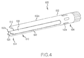
- FIG. 4-7 show a tool useful for implanting the screw and rod system.
- FIG. 1 shows a perspective view of system 100 .
- System 100 includes a bone screw 102 , a housing 104 having an outer surface 106 , a rod 108 , and a compressive member 110 , such as, a setscrew.
- Housing 104 may contain one or more first mating surfaces 112 .
- First mating surfaces 112 are designed to mate with a tool (described further below).
- First mating surfaces 112 may include an alignment ridge 112 a , which also may be a dimple, detent, protrusion, rib, or the like.
- Alignment ridge 112 a conversely may be an alignment channel 112 b as shown in phantom.
- setscrew 110 typically has one or more second mating surface 114 to mate with a tool (not specifically shown but generally understood in the art).
- first mating surfaces 112 are actually slots on an outer surface 106 of housing 104 . While shown as slots, first mating surfaces 112 may be any number of designs including one or more dimples, hex detents, or other equivalent mechanisms as are known in the art.
- Second mating surface 114 is shown with a hex shape to accept a hex driver useful in threading the setscrew. Of course, one of ordinary skill in the art would recognize other and equivalent first and second mating surfaces 112 , 114 are possible.
- Housing 104 may be referred to as a coupling device, seat, or anchor.
- Housing 104 has a bone facing surface 302 , at least one sidewall 304 having an outer surface 106 and an inner surface 306 (best seen in FIG. 2 ), first mating surfaces 112 , a pair of opposed slots 308 in sidewall 304 , a top edge 310 , and a through hole 312 extending from top edge 310 to bone facing surface 302 .
- Top edge 310 may have alignment points 320 , which will be explained in more detail below.
- Alignment points 320 may be protrusions (as shown by 320 p ) or detents (as shown by 320 d ) as a matter of design choice, but it is believed detents would provided a lower profile.
- the housing 104 is shown with one cylindrically shaped sidewall 304 . It is believed providing housing 104 as a cylindrical shape reduces the profile of the device, but other shapes are possible, such as cubic or the like. If housing 104 had multiple sidewalls 304 , the edges between the multiple sides should be beveled or rounded to inhibit tissue trauma.
- Bone screw 102 will now be described with reference to FIG. 3 . While a particular bone screw 102 is described for completeness, any conventional bone screw is usable with the technology of the present invention.
- Bone screw 102 has a threaded portion 502 , a transition portion 504 , and a head portion 506 .
- Threaded portion 502 can use any conventional thread, but as shown, threaded portion 502 has a shaft 508 and threads 510 machined such that shaft 508 has an increasing diameter from the tip 512 to transition portion 504 . Further, threads 510 become relatively thicker towards transition portion 504 . Designing threaded portion 502 in this fashion increases the frictional engagement of bone screw 102 in bone and generally increases the screw strength.
- bone growth channels 509 may be provided in shaft 508 , thread 510 , or a combination thereof. It is believed micro-channels 509 in thread 510 facilitates bone growth and fusion of the screw to bone.
- Transition portion 504 comprises the portion of bone screw 102 between threaded portion 502 and head portion 506 . Transition portion 504 could be integrated into threaded portion 502 . Transition portion 504 may be straight, curved, bowed, flared, or the like to transition threaded portion 502 to head portion 506 .
- Head 506 is shown with a convex outer surface 514 to cooperatively engage a corresponding concave surface in housing 104 , not specifically shown by generally understood in the art.
- the convex outer surface 514 being designed to cooperatively engage the concave surface in housing 104 allows for polyaxial orientation of bone screw 102 with respect to housing 104 .
- Head 506 is shown as a conventional flat head screw with a slot 516 to receive a tool, such as a screw driver. Rotation of the tool while engaged with slot 516 drive bone screw 102 into the associated bone.
- Tool 600 is provided to facilitate implanting the above described screws and rods.
- Tool 600 would typically be inserted through the skin of a patient after sufficient dilation.
- Tool 600 comprises a series of sleeves that will be explained in turn.
- Tool 600 includes a first, outer sleeve 602 , sometimes referred to first or outer.
- First sleeve 602 has an inner surface 602 s and an outer surface 602 o .
- Inner surface 602 s defines a first sleeve diameter d 1 .
- First sleeve 602 includes a distal end 604 releasably connectable to housing 104 at first mating surfaces 112 , as will be explained further below.
- First sleeve 602 has a proximate end 606 residing external to the patient. Extending from distal end 604 towards proximate end 606 are slots 608 separating tabs 610 . Slots 608 include a flared portion 609 . Flared portion 609 increases the flexibility or elasticity of tabs 610 , which is useful in connecting first sleeve 602 to housing 104 . Tabs 610 include first tool mating surface 612 to engage first mating surfaces 112 on housing 104 . Rotating first sleeve 602 causes housing 104 to cause tabs 610 to expand.
- first tool mating surfaces 612 which are shown as protrusions, slide into first mating surfaces 112 , which are shown as detents or grooves.
- Flexible tabs 610 collapse towards each other allowing outer sleeve 602 to grip housing 104 when first tool mating surface 612 align with first mating surfaces 112 .
- First mating surface 612 optionally may be provided with an alignment dimple 614 to mate with alignment ridge 112 a.
- a second or inner sleeve 620 is provided to slidingly engage outer sleeve 602 .
- Second sleeve 620 has a second outer surface 620 o defining an second diameter d 2 which is less than d 1 and allows second sleeve to fit inside first sleeve in a sliding relation.
- Second sleeve 620 comprises distal end 622 and proximate end 624 .
- Distal end 622 includes alignment portions 626 (which may be protrusions 626 p (as shown) to mate with alignment detents 320 d or which may be alignment detents 626 d to mate with alignment protrusions 320 p ).
- Alignment portion 626 mate with corresponding alignment points 320 along top edge 310 of housing 104 .
- Second sleeve 620 includes at least one, but as shown two, alignment channels 628 . Alignment channel 628 are shown opposite each other but could be otherwise configured. First sleeve 602 has at least one, but as shown two, corresponding alignment tabs 630 attached to an inner surface 602 s . Alignment channel(s) 628 and alignment tab(s) 630 are matched such that when second sleeve 620 is slidably received in first sleeve 602 , alignment tab(s) 630 move along and engage alignment slot(s) 628 to facilitate mating alignment portion 626 with alignment point 320 . Second sleeve 620 , optionally, may include one or more alignment tracks 625 . Alignment tracks 625 fittingly engage with alignment ridge 627 (shown in FIG. 5 ) to facilitate alignment points 320 aligning with alignment portions 626 and alignment channels 628 aligning with alignment tabs 630 .
- second sleeve 620 acts as a strengthening member to inhibit torque from causing first sleeve 602 to twist off of housing 104 while driving, for example, bone screw into bone.
- pin alignment tabs 630 may have a flared surface 637 .
- alignment channels 628 may be tapered to pinch or grasp tabs 630 .
- a connector 650 couples the proximate ends of the sleeves 602 and 620 together.
- connector 650 causes first sleeve 602 and second sleeve 620 to clamp and lock to housing 104 .
- connector 650 may have a shaft 652 with outer surface 654 having threads 656 .
- Inner surface 602 s of first sleeve 602 at the proximate end would have corresponding threads 658 .
- Shaft 652 would have a pushing surface 660 that abuts a proximate edge 662 of second sleeve 620 .
- Threading connector 650 onto corresponding threads 658 pulls first sleeve 602 in direction A and pushes second sleeve in a direction B, opposite direction A by causing pushing surface 660 to push down on proximate edge 662 .
- the relative forces between first sleeve 602 and second sleeve 620 clamps first sleeve 602 and second 620 to housing 104 .
- first tool mating surface 612 to applies a force against first mating surfaces 112 in direction A and the distail edge of second sleeve 620 applies a force against top edge 310 of housing 104 providing a clamping force.
- Connector 650 may have a tool mating surface 660 to allow a tool to thread the connector 650 to and from first sleeve 602 .
- a bone screw drive can be inserted through second sleeve 620 to thread bone screw 102 into the bone.
- First and second sleeve 602 and 620 provide counter torque to allow driving the screw.
Abstract
Description
Claims (8)
Priority Applications (1)
| Application Number | Priority Date | Filing Date | Title |
|---|---|---|---|
| US13/540,497 US9314280B2 (en) | 2006-11-10 | 2012-07-02 | Minimally invasive tool to facilitate implanting a pedicle screw and housing |
Applications Claiming Priority (3)
| Application Number | Priority Date | Filing Date | Title |
|---|---|---|---|
| US86536506P | 2006-11-10 | 2006-11-10 | |
| US11/938,073 US8211110B1 (en) | 2006-11-10 | 2007-11-09 | Minimally invasive tool to facilitate implanting a pedicle screw and housing |
| US13/540,497 US9314280B2 (en) | 2006-11-10 | 2012-07-02 | Minimally invasive tool to facilitate implanting a pedicle screw and housing |
Related Parent Applications (1)
| Application Number | Title | Priority Date | Filing Date |
|---|---|---|---|
| US11/938,073 Continuation US8211110B1 (en) | 2006-11-10 | 2007-11-09 | Minimally invasive tool to facilitate implanting a pedicle screw and housing |
Publications (2)
| Publication Number | Publication Date |
|---|---|
| US20130144349A1 US20130144349A1 (en) | 2013-06-06 |
| US9314280B2 true US9314280B2 (en) | 2016-04-19 |
Family
ID=46320105
Family Applications (2)
| Application Number | Title | Priority Date | Filing Date |
|---|---|---|---|
| US11/938,073 Active 2028-10-22 US8211110B1 (en) | 2006-11-10 | 2007-11-09 | Minimally invasive tool to facilitate implanting a pedicle screw and housing |
| US13/540,497 Active 2029-04-04 US9314280B2 (en) | 2006-11-10 | 2012-07-02 | Minimally invasive tool to facilitate implanting a pedicle screw and housing |
Family Applications Before (1)
| Application Number | Title | Priority Date | Filing Date |
|---|---|---|---|
| US11/938,073 Active 2028-10-22 US8211110B1 (en) | 2006-11-10 | 2007-11-09 | Minimally invasive tool to facilitate implanting a pedicle screw and housing |
Country Status (1)
| Country | Link |
|---|---|
| US (2) | US8211110B1 (en) |
Cited By (4)
| Publication number | Priority date | Publication date | Assignee | Title |
|---|---|---|---|---|
| US11406431B1 (en) | 2021-05-10 | 2022-08-09 | Warsaw Orthopedic, Inc. | Systems and methods of use and modular instruments with a lateral reducer |
| US11439442B2 (en) | 2020-04-16 | 2022-09-13 | Warsaw Orthopedic, Inc. | Modular screw system with head locker and derotator |
| US11617603B2 (en) | 2020-12-09 | 2023-04-04 | Warsaw Orthopedic, Inc. | Modular surgical instrument system with ratcheting reduction mechanism |
| US11617602B2 (en) | 2020-04-16 | 2023-04-04 | Medtronic, Inc. | Systems, methods of use and surgical instruments employing a secure slide lock to fasten a head |
Families Citing this family (52)
| Publication number | Priority date | Publication date | Assignee | Title |
|---|---|---|---|---|
| US7833250B2 (en) | 2004-11-10 | 2010-11-16 | Jackson Roger P | Polyaxial bone screw with helically wound capture connection |
| US7862587B2 (en) | 2004-02-27 | 2011-01-04 | Jackson Roger P | Dynamic stabilization assemblies, tool set and method |
| US8876868B2 (en) | 2002-09-06 | 2014-11-04 | Roger P. Jackson | Helical guide and advancement flange with radially loaded lip |
| US7621918B2 (en) | 2004-11-23 | 2009-11-24 | Jackson Roger P | Spinal fixation tool set and method |
| US7377923B2 (en) | 2003-05-22 | 2008-05-27 | Alphatec Spine, Inc. | Variable angle spinal screw assembly |
| US7766915B2 (en) | 2004-02-27 | 2010-08-03 | Jackson Roger P | Dynamic fixation assemblies with inner core and outer coil-like member |
| US7776067B2 (en) | 2005-05-27 | 2010-08-17 | Jackson Roger P | Polyaxial bone screw with shank articulation pressure insert and method |
| US7967850B2 (en) | 2003-06-18 | 2011-06-28 | Jackson Roger P | Polyaxial bone anchor with helical capture connection, insert and dual locking assembly |
| US8936623B2 (en) | 2003-06-18 | 2015-01-20 | Roger P. Jackson | Polyaxial bone screw assembly |
| US7179261B2 (en) | 2003-12-16 | 2007-02-20 | Depuy Spine, Inc. | Percutaneous access devices and bone anchor assemblies |
| US11419642B2 (en) | 2003-12-16 | 2022-08-23 | Medos International Sarl | Percutaneous access devices and bone anchor assemblies |
| CA2555868C (en) | 2004-02-27 | 2011-09-06 | Roger P. Jackson | Orthopedic implant rod reduction tool set and method |
| US7160300B2 (en) | 2004-02-27 | 2007-01-09 | Jackson Roger P | Orthopedic implant rod reduction tool set and method |
| US9050148B2 (en) | 2004-02-27 | 2015-06-09 | Roger P. Jackson | Spinal fixation tool attachment structure |
| US8152810B2 (en) | 2004-11-23 | 2012-04-10 | Jackson Roger P | Spinal fixation tool set and method |
| US11241261B2 (en) | 2005-09-30 | 2022-02-08 | Roger P Jackson | Apparatus and method for soft spinal stabilization using a tensionable cord and releasable end structure |
| US8926672B2 (en) | 2004-11-10 | 2015-01-06 | Roger P. Jackson | Splay control closure for open bone anchor |
| US9168069B2 (en) | 2009-06-15 | 2015-10-27 | Roger P. Jackson | Polyaxial bone anchor with pop-on shank and winged insert with lower skirt for engaging a friction fit retainer |
| US8444681B2 (en) | 2009-06-15 | 2013-05-21 | Roger P. Jackson | Polyaxial bone anchor with pop-on shank, friction fit retainer and winged insert |
| US7901437B2 (en) | 2007-01-26 | 2011-03-08 | Jackson Roger P | Dynamic stabilization member with molded connection |
| CA2670988C (en) | 2006-12-08 | 2014-03-25 | Roger P. Jackson | Tool system for dynamic spinal implants |
| CA2739997C (en) | 2008-08-01 | 2013-08-13 | Roger P. Jackson | Longitudinal connecting member with sleeved tensioned cords |
| US8439923B2 (en) * | 2008-10-17 | 2013-05-14 | Omni Surgical LLC | Poly-axial pedicle screw assembly |
| US8998959B2 (en) | 2009-06-15 | 2015-04-07 | Roger P Jackson | Polyaxial bone anchors with pop-on shank, fully constrained friction fit retainer and lock and release insert |
| US11229457B2 (en) | 2009-06-15 | 2022-01-25 | Roger P. Jackson | Pivotal bone anchor assembly with insert tool deployment |
| US9668771B2 (en) | 2009-06-15 | 2017-06-06 | Roger P Jackson | Soft stabilization assemblies with off-set connector |
| EP2757988A4 (en) | 2009-06-15 | 2015-08-19 | Jackson Roger P | Polyaxial bone anchor with pop-on shank and winged insert with friction fit compressive collet |
| CN103917181A (en) | 2009-06-15 | 2014-07-09 | 罗杰.P.杰克逊 | Polyaxial bone anchor with pop-on shank and friction fit retainer with low profile edge lock |
| US8556904B2 (en) * | 2011-05-05 | 2013-10-15 | Warsaw Orthopedic, Inc. | Anchors extender assemblies and methods for using |
| US8911479B2 (en) | 2012-01-10 | 2014-12-16 | Roger P. Jackson | Multi-start closures for open implants |
| US8439924B1 (en) * | 2012-04-02 | 2013-05-14 | Warsaw Orthopedic, Inc. | Spinal implant system and method |
| US8911478B2 (en) | 2012-11-21 | 2014-12-16 | Roger P. Jackson | Splay control closure for open bone anchor |
| US10058354B2 (en) | 2013-01-28 | 2018-08-28 | Roger P. Jackson | Pivotal bone anchor assembly with frictional shank head seating surfaces |
| US8852239B2 (en) | 2013-02-15 | 2014-10-07 | Roger P Jackson | Sagittal angle screw with integral shank and receiver |
| US20140276895A1 (en) * | 2013-03-15 | 2014-09-18 | Roger P. Jackson | Tower tool for minimally invasive surgery |
| US9370383B2 (en) * | 2013-03-15 | 2016-06-21 | Zimmer Biomet Spine, Inc. | Minimally invasive splitable pedicle screw extender |
| DE102013108362A1 (en) | 2013-08-02 | 2015-02-05 | Aesculap Ag | Medical instrument for holding and manipulating a surgical fastener and spinal stabilization system |
| US9566092B2 (en) | 2013-10-29 | 2017-02-14 | Roger P. Jackson | Cervical bone anchor with collet retainer and outer locking sleeve |
| EP2881053B1 (en) | 2013-12-09 | 2018-01-31 | Biedermann Technologies GmbH & Co. KG | Extension device for a bone anchor, in particular for minimally invasive surgery |
| US9717533B2 (en) | 2013-12-12 | 2017-08-01 | Roger P. Jackson | Bone anchor closure pivot-splay control flange form guide and advancement structure |
| US9451993B2 (en) | 2014-01-09 | 2016-09-27 | Roger P. Jackson | Bi-radial pop-on cervical bone anchor |
| JP6623168B2 (en) | 2014-03-26 | 2019-12-18 | メダクタ・インターナショナル・ソシエテ・アノニム | Device for implanting a surgical screwdriver |
| US9597119B2 (en) | 2014-06-04 | 2017-03-21 | Roger P. Jackson | Polyaxial bone anchor with polymer sleeve |
| US10064658B2 (en) | 2014-06-04 | 2018-09-04 | Roger P. Jackson | Polyaxial bone anchor with insert guides |
| EP2957246B1 (en) * | 2014-06-17 | 2017-04-19 | Biedermann Technologies GmbH & Co. KG | Extension device for a bone anchor, in particular for minimally invasive surgery |
| US10779866B2 (en) | 2016-12-29 | 2020-09-22 | K2M, Inc. | Rod reducer assembly |
| USD879965S1 (en) * | 2017-05-16 | 2020-03-31 | Wiltrom Co., Ltd. | Pedicle screw |
| CN107115140B (en) * | 2017-05-23 | 2024-01-02 | 温州医科大学附属第二医院温州医科大学附属育英儿童医院 | Internal fixing device for spinal column reinforced pedicle screw |
| USD879299S1 (en) * | 2017-05-24 | 2020-03-24 | Wiltrom Co., Ltd. | Spinal screw |
| US11484350B2 (en) | 2018-12-13 | 2022-11-01 | Zimmer Biomet Spine, Inc. | Split tower for a bone anchor |
| US11559337B2 (en) | 2018-12-14 | 2023-01-24 | Zimmer Biomet Spine, Inc. | Expended tab reinforcement sleeve |
| EP4301257A1 (en) * | 2021-03-05 | 2024-01-10 | Medos International Sarl | Multi-feature polyaxial screw |
Citations (22)
| Publication number | Priority date | Publication date | Assignee | Title |
|---|---|---|---|---|
| US2990570A (en) | 1958-03-24 | 1961-07-04 | Stanley Works | Snap-on hinge |
| US5530998A (en) | 1994-10-12 | 1996-07-02 | Hurst; Carl P. | Twist and snap fastener made of identical mating parts |
| US6004326A (en) | 1997-09-10 | 1999-12-21 | United States Surgical | Method and instrumentation for implant insertion |
| US6183472B1 (en) | 1998-04-09 | 2001-02-06 | Howmedica Gmbh | Pedicle screw and an assembly aid therefor |
| US20040039384A1 (en) | 2002-08-21 | 2004-02-26 | Boehm Frank H. | Device and method for pertcutaneous placement of lumbar pedicle screws and connecting rods |
| US20040147937A1 (en) | 2003-01-24 | 2004-07-29 | Depuy Spine, Inc. | Spinal rod approximators |
| US20040144194A1 (en) | 2000-05-01 | 2004-07-29 | James Allen | Adjustable brake, clutch and accelerator pedals |
| US20050065517A1 (en) | 2003-09-24 | 2005-03-24 | Chin Kingsley Richard | Methods and devices for improving percutaneous access in minimally invasive surgeries |
| US20050067815A1 (en) | 2003-09-25 | 2005-03-31 | Eugene Dearden | Airbag cover emblem attachment apparatus and method |
| US20050131408A1 (en) * | 2003-12-16 | 2005-06-16 | Sicvol Christopher W. | Percutaneous access devices and bone anchor assemblies |
| US20050137593A1 (en) | 2000-10-02 | 2005-06-23 | Sulzer Spine-Tech Inc. | Temporary spinal fixation apparatuses and methods |
| US20050192579A1 (en) * | 2004-02-27 | 2005-09-01 | Jackson Roger P. | Orthopedic implant rod reduction tool set and method |
| US20050228400A1 (en) | 2004-03-31 | 2005-10-13 | Chao Nam T | Instrument for inserting, adjusting and removing pedicle screws and other orthopedic implants |
| US20060069391A1 (en) * | 2004-02-27 | 2006-03-30 | Jackson Roger P | Spinal fixation tool attachment structure |
| US20060074445A1 (en) | 2004-09-29 | 2006-04-06 | David Gerber | Less invasive surgical system and methods |
| US20060074418A1 (en) | 2004-09-24 | 2006-04-06 | Jackson Roger P | Spinal fixation tool set and method for rod reduction and fastener insertion |
| US20060149245A1 (en) * | 2004-06-09 | 2006-07-06 | Spinal Generations, Llc | Bone fixation system |
| US20060200132A1 (en) | 2005-03-04 | 2006-09-07 | Chao Nam T | Instruments and methods for manipulating a vertebra |
| US20060247658A1 (en) | 2005-04-28 | 2006-11-02 | Pond John D Jr | Instrument and method for guiding surgical implants and instruments during surgery |
| US20060247630A1 (en) | 2005-04-27 | 2006-11-02 | Andrew Iott | Percutaneous vertebral stabilization system |
| US20070233155A1 (en) * | 2005-12-07 | 2007-10-04 | Lovell John R | Device and method for holding and inserting one or more components of a pedicle screw assembly |
| US20090143828A1 (en) * | 2007-10-04 | 2009-06-04 | Shawn Stad | Methods and Devices For Minimally Invasive Spinal Connection Element Delivery |
-
2007
- 2007-11-09 US US11/938,073 patent/US8211110B1/en active Active
-
2012
- 2012-07-02 US US13/540,497 patent/US9314280B2/en active Active
Patent Citations (22)
| Publication number | Priority date | Publication date | Assignee | Title |
|---|---|---|---|---|
| US2990570A (en) | 1958-03-24 | 1961-07-04 | Stanley Works | Snap-on hinge |
| US5530998A (en) | 1994-10-12 | 1996-07-02 | Hurst; Carl P. | Twist and snap fastener made of identical mating parts |
| US6004326A (en) | 1997-09-10 | 1999-12-21 | United States Surgical | Method and instrumentation for implant insertion |
| US6183472B1 (en) | 1998-04-09 | 2001-02-06 | Howmedica Gmbh | Pedicle screw and an assembly aid therefor |
| US20040144194A1 (en) | 2000-05-01 | 2004-07-29 | James Allen | Adjustable brake, clutch and accelerator pedals |
| US20050137593A1 (en) | 2000-10-02 | 2005-06-23 | Sulzer Spine-Tech Inc. | Temporary spinal fixation apparatuses and methods |
| US20040039384A1 (en) | 2002-08-21 | 2004-02-26 | Boehm Frank H. | Device and method for pertcutaneous placement of lumbar pedicle screws and connecting rods |
| US20040147937A1 (en) | 2003-01-24 | 2004-07-29 | Depuy Spine, Inc. | Spinal rod approximators |
| US20050065517A1 (en) | 2003-09-24 | 2005-03-24 | Chin Kingsley Richard | Methods and devices for improving percutaneous access in minimally invasive surgeries |
| US20050067815A1 (en) | 2003-09-25 | 2005-03-31 | Eugene Dearden | Airbag cover emblem attachment apparatus and method |
| US20050131408A1 (en) * | 2003-12-16 | 2005-06-16 | Sicvol Christopher W. | Percutaneous access devices and bone anchor assemblies |
| US20050192579A1 (en) * | 2004-02-27 | 2005-09-01 | Jackson Roger P. | Orthopedic implant rod reduction tool set and method |
| US20060069391A1 (en) * | 2004-02-27 | 2006-03-30 | Jackson Roger P | Spinal fixation tool attachment structure |
| US20050228400A1 (en) | 2004-03-31 | 2005-10-13 | Chao Nam T | Instrument for inserting, adjusting and removing pedicle screws and other orthopedic implants |
| US20060149245A1 (en) * | 2004-06-09 | 2006-07-06 | Spinal Generations, Llc | Bone fixation system |
| US20060074418A1 (en) | 2004-09-24 | 2006-04-06 | Jackson Roger P | Spinal fixation tool set and method for rod reduction and fastener insertion |
| US20060074445A1 (en) | 2004-09-29 | 2006-04-06 | David Gerber | Less invasive surgical system and methods |
| US20060200132A1 (en) | 2005-03-04 | 2006-09-07 | Chao Nam T | Instruments and methods for manipulating a vertebra |
| US20060247630A1 (en) | 2005-04-27 | 2006-11-02 | Andrew Iott | Percutaneous vertebral stabilization system |
| US20060247658A1 (en) | 2005-04-28 | 2006-11-02 | Pond John D Jr | Instrument and method for guiding surgical implants and instruments during surgery |
| US20070233155A1 (en) * | 2005-12-07 | 2007-10-04 | Lovell John R | Device and method for holding and inserting one or more components of a pedicle screw assembly |
| US20090143828A1 (en) * | 2007-10-04 | 2009-06-04 | Shawn Stad | Methods and Devices For Minimally Invasive Spinal Connection Element Delivery |
Non-Patent Citations (1)
| Title |
|---|
| Acta Orthop Scand article dated Jun. 1984, by Bostman O. Myllynen P. Riska EB. |
Cited By (5)
| Publication number | Priority date | Publication date | Assignee | Title |
|---|---|---|---|---|
| US11439442B2 (en) | 2020-04-16 | 2022-09-13 | Warsaw Orthopedic, Inc. | Modular screw system with head locker and derotator |
| US11617602B2 (en) | 2020-04-16 | 2023-04-04 | Medtronic, Inc. | Systems, methods of use and surgical instruments employing a secure slide lock to fasten a head |
| US11717331B2 (en) | 2020-04-16 | 2023-08-08 | Warsaw Orthopedic, Inc. | Systems, methods of use and surgical instruments employing a secure slide lock to fasten a head |
| US11617603B2 (en) | 2020-12-09 | 2023-04-04 | Warsaw Orthopedic, Inc. | Modular surgical instrument system with ratcheting reduction mechanism |
| US11406431B1 (en) | 2021-05-10 | 2022-08-09 | Warsaw Orthopedic, Inc. | Systems and methods of use and modular instruments with a lateral reducer |
Also Published As
| Publication number | Publication date |
|---|---|
| US20130144349A1 (en) | 2013-06-06 |
| US8211110B1 (en) | 2012-07-03 |
Similar Documents
| Publication | Publication Date | Title |
|---|---|---|
| US9314280B2 (en) | Minimally invasive tool to facilitate implanting a pedicle screw and housing | |
| US11337733B2 (en) | Derotation apparatus for treating spinal irregularities | |
| US11020153B2 (en) | Method and instruments for interbody fusion and posterior fixation through a single incision | |
| USRE47646E1 (en) | Method and associated instrumentation for installation of spinal dynamic stabilization system | |
| EP2254494B1 (en) | System for insertion of flexible spinal stabilization element | |
| US8096996B2 (en) | Rod reducer | |
| US8992536B2 (en) | Coplanar deformity correction system | |
| EP2408389B1 (en) | Press-on link for surgical screws | |
| US8246659B2 (en) | Installation systems for spinal stabilization system and related methods | |
| US9649137B2 (en) | Spinal stabilization system | |
| US10085778B2 (en) | Rod reducer instrument for spinal surgery | |
| US20170333085A1 (en) | Snap-on multi-planar and mono-planar receiver assemblies having integral and multi-part multipurpose positioners for pivoting and non-pivoting retainers | |
| US20130345756A1 (en) | Rod coupling assembly and methods for bone fixation | |
| US20070167954A1 (en) | Percutaneous Access Devices And Bone Anchor Assemblies | |
| US20090005815A1 (en) | Dynamic stabilization system | |
| US20240041500A1 (en) | Pivotal bone anchor assembly with biasing member for pre-lock friction fit | |
| EP2967692A1 (en) | Minimally invasive splitable pedicle screw extender | |
| US20220079629A1 (en) | Bone fusion device, system and methods | |
| US20170189070A1 (en) | Fusion systems and methods of assembly and use | |
| US20060167465A1 (en) | System for facilitating attachment of a delivery instrument with a bone screw | |
| JP7261902B2 (en) | Polyaxial surgical screw and device for implanting same |
Legal Events
| Date | Code | Title | Description |
|---|---|---|---|
| AS | Assignment |
Owner name: LANX, INC., COLORADO Free format text: ASSIGNMENT OF ASSIGNORS INTEREST;ASSIGNOR:CORIN, JAMES;REEL/FRAME:029850/0325 Effective date: 20080311 |
|
| AS | Assignment |
Owner name: LANX, INC., COLORADO Free format text: ASSIGNMENT OF ASSIGNORS INTEREST;ASSIGNOR:CORIN, JAMES;REEL/FRAME:029827/0216 Effective date: 20080311 |
|
| AS | Assignment |
Owner name: LANX, INC., COLORADO Free format text: ASSIGNMENT OF ASSIGNORS INTEREST;ASSIGNORS:CORIN, JAMES;FULTON, MICHAEL;SIGNING DATES FROM 20100728 TO 20100916;REEL/FRAME:029841/0645 |
|
| AS | Assignment |
Owner name: BANK OF AMERICA, N.A., AS ADMINISTRATIVE AGENT, NO Free format text: SECURITY AGREEMENT;ASSIGNOR:LANX, INC.;REEL/FRAME:032086/0664 Effective date: 20140113 |
|
| AS | Assignment |
Owner name: LANX, INC., COLORADO Free format text: RELEASE OF SECURITY INTEREST IN PATENTS RECORDED AT REEL 032086/ FRAME 0664;ASSIGNOR:BANK OF AMERICA, N.A., AS ADMINISTRATIVE AGENT;REEL/FRAME:037155/0041 Effective date: 20150624 |
|
| AS | Assignment |
Owner name: ZIMMER BIOMET SPINE, INC., COLORADO Free format text: CHANGE OF NAME;ASSIGNOR:LANX, INC.;REEL/FRAME:037761/0231 Effective date: 20150730 |
|
| STCF | Information on status: patent grant |
Free format text: PATENTED CASE |
|
| AS | Assignment |
Owner name: ZIMMER BIOMET SPINE, INC., COLORADO Free format text: CORRECTIVE ASSIGNMENT TO CORRECT THE REMOVE APPL. NO. 14/828,714 PREVIOUSLY RECORDED AT REEL: 037761 FRAME: 0231. ASSIGNOR(S) HEREBY CONFIRMS THE CHANGE OF NAME;ASSIGNOR:LANX, INC.;REEL/FRAME:038951/0064 Effective date: 20150730 |
|
| MAFP | Maintenance fee payment |
Free format text: PAYMENT OF MAINTENANCE FEE, 4TH YEAR, LARGE ENTITY (ORIGINAL EVENT CODE: M1551); ENTITY STATUS OF PATENT OWNER: LARGE ENTITY Year of fee payment: 4 |
|
| AS | Assignment |
Owner name: JPMORGAN CHASE BANK, N.A., AS ADMINISTRATIVE AGENT, NEW YORK Free format text: SECURITY INTEREST;ASSIGNORS:BIOMET 3I, LLC;EBI, LLC;ZIMMER BIOMET SPINE, INC.;AND OTHERS;REEL/FRAME:059293/0213 Effective date: 20220228 |
|
| FEPP | Fee payment procedure |
Free format text: MAINTENANCE FEE REMINDER MAILED (ORIGINAL EVENT CODE: REM.); ENTITY STATUS OF PATENT OWNER: LARGE ENTITY |