US9299523B1 - Switching device assembly and adapter assembly therefor - Google Patents
Switching device assembly and adapter assembly therefor Download PDFInfo
- Publication number
- US9299523B1 US9299523B1 US14/568,296 US201414568296A US9299523B1 US 9299523 B1 US9299523 B1 US 9299523B1 US 201414568296 A US201414568296 A US 201414568296A US 9299523 B1 US9299523 B1 US 9299523B1
- Authority
- US
- United States
- Prior art keywords
- adapter
- assembly
- switching device
- lug
- cable
- Prior art date
- Legal status (The legal status is an assumption and is not a legal conclusion. Google has not performed a legal analysis and makes no representation as to the accuracy of the status listed.)
- Active
Links
Images


Classifications
-
- H—ELECTRICITY
- H01—ELECTRIC ELEMENTS
- H01R—ELECTRICALLY-CONDUCTIVE CONNECTIONS; STRUCTURAL ASSOCIATIONS OF A PLURALITY OF MUTUALLY-INSULATED ELECTRICAL CONNECTING ELEMENTS; COUPLING DEVICES; CURRENT COLLECTORS
- H01R9/00—Structural associations of a plurality of mutually-insulated electrical connecting elements, e.g. terminal strips or terminal blocks; Terminals or binding posts mounted upon a base or in a case; Bases therefor
- H01R9/22—Bases, e.g. strip, block, panel
- H01R9/24—Terminal blocks
- H01R9/2408—Modular blocks
-
- H—ELECTRICITY
- H01—ELECTRIC ELEMENTS
- H01H—ELECTRIC SWITCHES; RELAYS; SELECTORS; EMERGENCY PROTECTIVE DEVICES
- H01H71/00—Details of the protective switches or relays covered by groups H01H73/00 - H01H83/00
- H01H71/10—Operating or release mechanisms
- H01H71/1045—Multiple circuits-breaker, e.g. for the purpose of dividing current or potential drop
-
- H—ELECTRICITY
- H01—ELECTRIC ELEMENTS
- H01H—ELECTRIC SWITCHES; RELAYS; SELECTORS; EMERGENCY PROTECTIVE DEVICES
- H01H71/00—Details of the protective switches or relays covered by groups H01H73/00 - H01H83/00
- H01H71/02—Housings; Casings; Bases; Mountings
- H01H71/0207—Mounting or assembling the different parts of the circuit breaker
-
- H—ELECTRICITY
- H01—ELECTRIC ELEMENTS
- H01R—ELECTRICALLY-CONDUCTIVE CONNECTIONS; STRUCTURAL ASSOCIATIONS OF A PLURALITY OF MUTUALLY-INSULATED ELECTRICAL CONNECTING ELEMENTS; COUPLING DEVICES; CURRENT COLLECTORS
- H01R31/00—Coupling parts supported only by co-operation with counterpart
- H01R31/06—Intermediate parts for linking two coupling parts, e.g. adapter
-
- H—ELECTRICITY
- H01—ELECTRIC ELEMENTS
- H01R—ELECTRICALLY-CONDUCTIVE CONNECTIONS; STRUCTURAL ASSOCIATIONS OF A PLURALITY OF MUTUALLY-INSULATED ELECTRICAL CONNECTING ELEMENTS; COUPLING DEVICES; CURRENT COLLECTORS
- H01R9/00—Structural associations of a plurality of mutually-insulated electrical connecting elements, e.g. terminal strips or terminal blocks; Terminals or binding posts mounted upon a base or in a case; Bases therefor
- H01R9/16—Fastening of connecting parts to base or case; Insulating connecting parts from base or case
- H01R9/18—Fastening by means of screw or nut
-
- H—ELECTRICITY
- H01—ELECTRIC ELEMENTS
- H01H—ELECTRIC SWITCHES; RELAYS; SELECTORS; EMERGENCY PROTECTIVE DEVICES
- H01H11/00—Apparatus or processes specially adapted for the manufacture of electric switches
- H01H11/0006—Apparatus or processes specially adapted for the manufacture of electric switches for converting electric switches
- H01H11/0031—Apparatus or processes specially adapted for the manufacture of electric switches for converting electric switches for allowing different types or orientation of connections to contacts
- H01H2011/0037—Apparatus or processes specially adapted for the manufacture of electric switches for converting electric switches for allowing different types or orientation of connections to contacts with removable or replaceable terminal blocks
-
- H—ELECTRICITY
- H01—ELECTRIC ELEMENTS
- H01H—ELECTRIC SWITCHES; RELAYS; SELECTORS; EMERGENCY PROTECTIVE DEVICES
- H01H71/00—Details of the protective switches or relays covered by groups H01H73/00 - H01H83/00
- H01H71/08—Terminals; Connections
-
- H—ELECTRICITY
- H01—ELECTRIC ELEMENTS
- H01R—ELECTRICALLY-CONDUCTIVE CONNECTIONS; STRUCTURAL ASSOCIATIONS OF A PLURALITY OF MUTUALLY-INSULATED ELECTRICAL CONNECTING ELEMENTS; COUPLING DEVICES; CURRENT COLLECTORS
- H01R4/00—Electrically-conductive connections between two or more conductive members in direct contact, i.e. touching one another; Means for effecting or maintaining such contact; Electrically-conductive connections having two or more spaced connecting locations for conductors and using contact members penetrating insulation
- H01R4/28—Clamped connections, spring connections
- H01R4/30—Clamped connections, spring connections utilising a screw or nut clamping member
- H01R4/36—Conductive members located under tip of screw
Definitions
- the disclosed concept pertains generally to switching device assemblies and, more particularly to switching device assemblies including for example electrical switching apparatus.
- the disclosed concept also pertains to adapter assemblies for switching device assemblies.
- a circuit breaker includes a non-conductive housing assembly that encloses a pair of separable contacts, an operating mechanism, a trip device, and other components. External to the enclosed space, the circuit breaker includes a terminal screw and a conductive terminal lug.
- the terminal lug is structured to be coupled to, and placed in electrical communication with, an external conductor, typically a line or load conductor.
- the external conductor may be, but is not limited to, a generally cylindrical cable. As such, the terminal lug may define a circular bore or opening into which the cable may be placed.
- the terminal screw is movably coupled to the terminal lug and is structured to secure the cable to the terminal lug. That is, the terminal screw is structured to move between two positions, a first position, wherein the terminal screw is not set, and a second position, wherein the terminal screw is set.
- the terminal lug may include a threaded bore that is contiguous with the opening for the cable. When the terminal screw is in the first position, the terminal screw does not bias the cable against the terminal lug. When the cable is located in the terminal lug bore and the terminal screw is moved into the set, second position, the terminal screw biases the cable against the terminal lug. That is, the terminal screw is drawn tight against the cable.
- Known electrical switching apparatus may become undesirably limited by the size of the cable they can receive. For example, in certain situations it may be necessary to employ a larger cable, such as to accommodate regulatory changes (e.g., changes to the National Electric Code (NEC)), or during a longer run period to address voltage drop issues.
- regulatory changes e.g., changes to the National Electric Code (NEC)
- NEC National Electric Code
- an adapter assembly for a switching device assembly of an electrical system includes at least one bus assembly.
- the switching device assembly includes at least one cable and at least one electrical switching apparatus.
- the cable is electrically connected to the bus assembly.
- the electrical switching apparatus includes a switching device lug member, a switching device lug fastener, and a load terminal. The switching device lug fastener connects the load terminal to the switching device lug member.
- the adapter assembly comprises: a housing assembly comprising a base member; and at least one interconnect assembly comprising: an adapter lug member coupled to the base member, the adapter lug member being structured to receive the cable, an adapter fastener structured to secure the cable to the adapter lug member, and an adapter terminal coupled to the adapter lug member and structured to be connected to the switching device lug member in order to provide an electrical pathway therebetween.
- a switching device assembly for an electrical system.
- the electrical system includes a bus assembly.
- the switching device assembly comprises: at least one cable electrically connected to the bus assembly; at least one electrical switching apparatus comprising: a switching device lug member, a switching device lug fastener, and a load terminal, the switching device lug fastener connecting the load terminal to the switching device lug member; and an adapter assembly comprising: a housing assembly comprising a base member, and at least one interconnect assembly comprising: an adapter lug member coupled to the base member, the adapter lug member receiving the cable, an adapter fastener securing the cable to the adapter lug member, and an adapter terminal coupled to each of the adapter lug member and the switching device lug member in order to provide an electrical pathway therebetween.
- FIG. 1 is an isometric view of a switching device assembly, partially shown in simplified form, and adapter assembly therefor, in accordance with a non-limiting embodiment of the disclosed concept;
- FIG. 2 is a top plan view of a portion of the switching device assembly and adapter assembly therefor of FIG. 1 , shown with the cover open in order to see hidden structures;
- FIG. 3 is an exploded isometric view of the adapter assembly of FIG. 2 ;
- FIG. 4 is a partially assembled isometric view of the adapter assembly of FIG. 3 , shown with the cover open in order to see hidden structures;
- FIG. 5 is a partially exploded isometric view of the adapter assembly of FIG. 4 ;
- FIG. 6 is another partially exploded isometric view of the adapter assembly of FIG. 5 ;
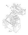
- FIG. 7 is a rear isometric view of a portion of the adapter assembly of FIG. 6 ;
- FIG. 8 is an exploded isometric view of a portion of the switching device assembly of FIG. 1 .
- number shall mean one or an integer greater than one (i.e., a plurality).
- coupling member refers to any suitable connecting or tightening mechanism expressly including, but not limited to, rivets, screws, bolts and the combinations of bolts and nuts (e.g., without limitation, lock nuts) and bolts, washers and nuts.
- the term “clearance hole” shall refer to a hole in a component, such as a cover, that is structured to receive an external component, such as a coupling member of a meter stack, in order to minimize clearance distance between the meter stack and the cover.
- lug member shall refer to a lug member that is structured to receive a cable, or range of cables, of a predetermined size.
- a 2/0 lug member is structured to receive cables up to a maximum size of a 2/0 AWG (American Wire Gauge) cable (i.e., cable having a cross sectional area of around 88 square millimeters per AWG standards, measured without insulation).
- a 4/0 lug member is structured to receive cables up to a maximum size of a 4/0 AWG cable (i.e., cable having a cross sectional area of around 141 square millimeters per AWG standards, measured without insulation).
- the term “batwing” shall refer to a recessed region in a lug member into which a cable is pressed, thereby strengthening the connection between the cable and the lug member.
- the phrase “directly received” shall mean that one component, such as a cable, extends into and engages another component, such as a lug member.
- the phrase “indirectly received” shall mean that one component, such as a cable, is spaced from (i.e., does not engage), but is electrically connected with another component, such as a lug member.
- FIG. 1 shows a switching device assembly 100 in accordance with a non-limiting embodiment of the disclosed concept.
- the example switching device assembly 100 is for an electrical system (e.g., meter stack 2 , shown in simplified form in phantom line drawing).
- the switching device assembly 100 includes a number of cables 104 , 106 (partially shown in simplified form in FIG. 1 ), a number of electrical switching apparatus (e.g., circuit breakers 120 , 150 ), and an adapter assembly 200 .
- the meter stack 2 includes a number of bus assemblies 4 , 6 .
- Each of the cables 104 , 106 is electrically connected with a respective one of the bus assemblies 4 , 6 .
- the cables 104 , 106 are each preferably 4/0 AWG cables (i.e., have a cross sectional area of around 141 square millimeters per AWG standards, measured without insulation).
- the circuit breakers 120 , 150 each include a respective switching device lug member 122 , 152 and a respective switching device lug fastener 124 , 154 .
- the switching device lug members 122 , 152 are each preferably 2/0 lug members.
- the switching device lug members 122 , 152 are not structured to directly receive the respective cables 104 , 106 .
- the adapter assembly 200 advantageously allows the relatively large cables 104 , 106 to be indirectly received by the respective switching device lug members 122 , 152 , thereby electrically connecting the respective cables 104 , 106 with the respective circuit breakers 120 , 150 .
- the example adapter assembly 200 includes a housing assembly 210 and a number of interconnect assemblies 310 , 350 (two are shown).
- the interconnect assemblies 310 , 350 each provide an electrical pathway between the respective cables 104 , 106 ( FIG. 1 and FIG. 2 ) and the respective circuit breakers 120 , 150 ( FIG. 1 and FIG. 2 ).
- the housing assembly 210 supports each of the interconnect assemblies 310 , 350 and electrically insulates the first interconnect assembly 310 from the second interconnect assembly 350 .
- the housing assembly 210 includes a base member 212 , a cover 214 , and a coupling member (e.g., screw 216 ).
- the base member 212 and the cover 214 are each preferably injection molded components (e.g., without limitation, made of a thermoplastic material).
- Each of the interconnect assemblies 310 , 350 includes a respective adapter lug member 312 , 352 , a respective adapter fastener 314 , 354 , a respective coupling member 318 , 358 , and a respective adapter terminal 320 , 360 .
- the adapter lug members 312 , 352 are each preferably 4/0 lug members that directly receive the respective cables 104 , 106 ( FIG. 1 and FIG. 2 ).
- Each of the adapter fasteners 314 , 354 is a set screw that secures a corresponding one of the cables 104 , 106 to the respective adapter lug members 312 , 352 .
- the adapter fastener 314 presses (i.e., forces) the cable 104 into the adapter lug member 312 .
- the adapter fastener 354 presses (i.e., forces) the cable 106 into the adapter lug member 352 .
- each of the adapter lug members 312 , 352 includes a number of batwings (two batwings 316 , 317 are shown on the adapter lug member 312 , and two batwings 356 , 357 are shown on the adapter lug member 352 ).
- the adapter fasteners 314 , 354 press the respective cables 104 , 106 ( FIG. 1 and FIG.
- the cover 214 of the housing assembly 210 is removably coupled to the base member 212 , and each of the adapter lug members 312 , 352 is coupled to the base member 212 and located internal with respect to the cover 214 and the base member 212 .
- the cover 214 and the base member 212 house and protect the adapter lug members 312 , 352 and the adapter fasteners 314 , 354 .
- the cover 214 is in part coupled to the base member 212 by a snap-fit mechanism.
- the base member 212 includes a number of slots 218 , 219 , 220 , 221 .
- the cover 214 includes a mounting portion 222 and a number of flexible retention members 226 , 230 , 234 , 238 .
- Each of the flexible retention members 226 , 230 , 234 , 238 includes a respective elongated portion 227 , 231 , 235 , 239 and a respective hook portion 228 , 232 , 236 , 240 .
- the elongated portions 227 , 231 , 235 , 239 extend from the mounting portion 222 .
- the hook portions 228 , 232 , 236 , 240 extend from the respective elongated portions 227 , 231 , 235 , 239 and are spaced from the mounting portion 222 .
- each of the flexible retention members 226 , 230 , 234 , 238 slides within a corresponding one of the slots 218 , 219 , 220 , 221 , and the hook portions 228 , 232 , 236 , 240 advantageously allow the cover 214 to be secured. In this manner, the flexible retention members 226 , 230 , 234 , 238 maintain the cover 214 on the base member 212
- the cover 214 has a thru hole 223 and the base member 212 has an aperture 213 .
- the screw 216 extends through the thru hole 223 and into the aperture 213 ( FIG. 6 ) in order to further couple the cover 214 to the base member 212 .
- the cover 214 is further secured to the base member 212 by way of the screw 216 .
- each of the adapter terminals 320 , 360 includes a first elongated portion 324 , 364 and a second elongated portion 326 , 366 extending from the first elongated portion 324 , 364 .
- the first elongated portions 324 , 364 are each at a respective angle 325 , 365 with respect to the second elongated portions 326 , 366 .
- the angles 325 , 365 are each preferably between 125 degrees and 145 degrees.
- the adapter lug members 312 , 352 ( FIG. 2 ) are oriented in a similar configuration with respect to the switching device lug members 122 , 152 ( FIG. 2 ). As shown in FIG.
- the switching device lug members 122 , 152 face in a first direction 121 , 151 and the adapter lug members 312 , 352 face in a second direction 311 , 351 .
- the first directions 121 , 151 are at an angle 123 , 153 of between 125 degrees and 145 degrees with respect to the second directions 311 , 351 .
- bending of the cables 104 , 106 is advantageously minimized.
- the cables 104 , 106 do not need to be bent any more than as depicted in FIG. 1 in order to be indirectly received by the circuit breakers 120 , 150 ( FIG. 1 and FIG.
- first elongated portions 324 , 364 are each coupled to the respective adapter lug members 312 , 352
- the second elongated portions 326 , 366 are each connected to the respective switching device lug members 122 , 152 .
- the adapter terminals 320 , 360 provide an electrical pathway between the respective adapter lug members 312 , 352 and the respective switching device lug members 122 , 152 .
- the adapter terminals 320 , 360 each have a respective thru hole 322 , 362 .
- the adapter lug members 312 , 352 each have an aperture 315 , 355 .
- the coupling members 318 , 358 extend through the respective thru holes 322 , 362 of the adapter terminals 320 , 360 and into the respective apertures 315 , 355 of the adapter lug members 312 , 352 .
- the coupling members 318 , 358 are connected with the respective adapter lug members 312 , 352 and the respective adapter terminals 320 , 360 in order to electrically connect the adapter lug members 312 , 352 to the adapter terminals 320 , 360 .
- the coupling members 318 , 358 also partially secure the adapter terminals 320 , 360 to the base member 212 .
- each of the adapter terminals 320 , 360 is also coupled to the base member 212 by a snap-fit mechanism.
- the base member 212 includes a number of flexible retention members 250 , 251 , 252 , 253 .
- the adapter terminal 320 is located between the flexible retention members 252 , 253 .
- the adapter terminal 360 is located between the flexible retention members 250 , 251 . It will be appreciated that during assembly, when the adapter terminals 320 , 360 are pressed between the respective flexible retention members 250 , 251 , 252 , 253 , the flexible retention members deflect in order to allow the respective adapter terminals 320 , 360 to be securely mounted on the base member 212 .
- the second elongated portions 326 , 366 of the adapter terminals 320 , 360 are structured to extend into the respective switching device lug members 122 , 152 .
- the load terminals 126 , 156 extend into the respective switching device lug members 122 , 152 .
- the adapter terminals 320 , 360 are located between the respective switching device lug fasteners 124 , 154 and the respective load terminals 126 , 156 .
- each of the switching device lug fasteners 124 , 154 forces (i.e., presses) the respective adapter terminal 320 , 360 into the respective load terminal 126 , 156 .
- the switching device lug fasteners 124 , 154 connect the respective load terminals 126 , 156 and the respective adapter terminals 320 , 360 to the respective switching device lug members 122 , 152 .
- each of the cables 104 , 106 is electrically connected with a corresponding one of the circuit breakers 120 , 150 .
- the adapter assembly 200 advantageously allows the relatively large cables 104 , 106 to be indirectly received by the respective circuit breakers 120 , 150 .
- the meter stack 2 further includes a plate member 8 (shown in simplified form in phantom line drawing) and a coupling member 10 (shown in simplified form in phantom line drawing) coupled to the plate member 8 .
- the plate member 8 partially overlays (i.e., when viewed from a top plan view, is on top of) the adapter assembly 200 and is coupled to the bus assemblies 4 , 6 .
- the cover 214 has a clearance hole 224 .
- the clearance hole 224 receives the coupling member 10 .
- the adapter assembly 200 advantageously accommodates the coupling member 10 without any undesirable interference. It will, however, be appreciated that having a clearance hole is not meant to be a limiting aspect to the disclosed concept. Specifically, suitable alternative adapter assemblies (not shown) employed in other electrical systems (not shown) may not require a clearance hole.
- the adapter assembly 200 or a similar suitable alternative adapter assembly may be implemented with other electrical systems (e.g., load centers). Additionally, while the disclosed concept has been described in association with the relatively large 4/0 AWG cables 104 , 106 ( FIG. 1 and FIG.
- a similar suitable alternative adapter assembly may be employed in order to perform the desired function of allowing a number of cables (not shown) of a given size to be indirectly received by a corresponding number of lug members (not shown) of a different size (i.e., lug members structured to receive a cable of a different size).
- the disclosed concept provides for an improved (e.g., without limitation, more versatile, more accommodating) switching device assembly 100 and adapter assembly 200 therefor, which among other benefits, allows a number of relatively large cables 104 , 106 to be indirectly received by a number of circuit breakers 120 , 150 , as desired.
Abstract
Description
Claims (20)
Priority Applications (2)
| Application Number | Priority Date | Filing Date | Title |
|---|---|---|---|
| US14/568,296 US9299523B1 (en) | 2014-12-12 | 2014-12-12 | Switching device assembly and adapter assembly therefor |
| CA2911355A CA2911355C (en) | 2014-12-12 | 2015-11-05 | Switching device assembly and adapter assembly therefor |
Applications Claiming Priority (1)
| Application Number | Priority Date | Filing Date | Title |
|---|---|---|---|
| US14/568,296 US9299523B1 (en) | 2014-12-12 | 2014-12-12 | Switching device assembly and adapter assembly therefor |
Publications (1)
| Publication Number | Publication Date |
|---|---|
| US9299523B1 true US9299523B1 (en) | 2016-03-29 |
Family
ID=55537565
Family Applications (1)
| Application Number | Title | Priority Date | Filing Date |
|---|---|---|---|
| US14/568,296 Active US9299523B1 (en) | 2014-12-12 | 2014-12-12 | Switching device assembly and adapter assembly therefor |
Country Status (2)
| Country | Link |
|---|---|
| US (1) | US9299523B1 (en) |
| CA (1) | CA2911355C (en) |
Cited By (3)
| Publication number | Priority date | Publication date | Assignee | Title |
|---|---|---|---|---|
| USD796455S1 (en) * | 2016-06-15 | 2017-09-05 | Eaton Corporation | Electrical terminal |
| DE102016113408A1 (en) * | 2016-07-20 | 2018-01-25 | Assa Abloy Sicherheitstechnik Gmbh | Electric door opening device with connection block for electrical connection with terminal block cover with lockable mounting leg |
| US10177515B2 (en) | 2017-05-17 | 2019-01-08 | Eaton Intelligent Power Limited | Lug assemblies and related electrical apparatus and methods |
Citations (78)
| Publication number | Priority date | Publication date | Assignee | Title |
|---|---|---|---|---|
| US2285928A (en) * | 1939-05-01 | 1942-06-09 | Cole Electric Products Co Inc | Electrical connector |
| US2780793A (en) * | 1954-12-08 | 1957-02-05 | Westinghouse Electric Corp | Screw-operated electrical connector |
| US2907978A (en) * | 1957-07-25 | 1959-10-06 | Thomas & Betts Corp | Electrical connector |
| US3066277A (en) * | 1958-04-21 | 1962-11-27 | Ite Circuit Breaker Ltd | Solderless connector |
| US3076952A (en) * | 1960-12-23 | 1963-02-05 | Gen Electric | Mounted electrical connector |
| US3165372A (en) * | 1962-03-29 | 1965-01-12 | Gen Electric | Cable connector assembly |
| US3335399A (en) * | 1965-06-16 | 1967-08-08 | Square D Co | Means for electrically interconnecting conductors of wire and blade types |
| US3344394A (en) * | 1966-05-16 | 1967-09-26 | Zinsco Electrical Products | Limited engagement lug assembly |
| US3638173A (en) * | 1969-11-12 | 1972-01-25 | Wadsworth Electric Mfg Co The | Electrical connecting lug |
| US3747052A (en) * | 1971-06-24 | 1973-07-17 | Gen Electric | Clamp for blade for higher rating dyna-mate caps |
| US3888560A (en) * | 1974-02-13 | 1975-06-10 | Gen Electric | Electrical terminal configuration |
| US3891298A (en) * | 1973-09-17 | 1975-06-24 | Westinghouse Electric Corp | Clip connected terminal lug |
| US4027940A (en) * | 1976-08-10 | 1977-06-07 | Amerace Corporation | Electrical connector with captive clamping jaw |
| US4171152A (en) * | 1977-08-13 | 1979-10-16 | C. A. Weidmuller Kg | Terminal for printed circuits |
| US4213669A (en) * | 1978-09-11 | 1980-07-22 | Gte Sylvania Wiring Devices Incorporated | Terminal collar |
| US4603376A (en) * | 1984-06-19 | 1986-07-29 | Westinghouse Electric Corp. | Terminal assembly for circuit breaker and similar apparatus |
| US4669806A (en) * | 1984-05-09 | 1987-06-02 | Karl Lumberg Gmbh & Co. | Terminal strip connector block |
| US4693542A (en) * | 1984-12-12 | 1987-09-15 | Cgee Alsthom | Electrical screw connection |
| US5005104A (en) * | 1990-08-16 | 1991-04-02 | Westinghouse Electric Corp. | Clip-connected terminal conductor assembly |
| US5030131A (en) * | 1987-03-19 | 1991-07-09 | Connector Manufacturing Company | Electrical terminal connector |
| US5064384A (en) * | 1990-12-04 | 1991-11-12 | Square D Company | Jumper assembly for multiple breaker application |
| US5107396A (en) * | 1991-06-03 | 1992-04-21 | General Electric Company | Circuit breaker combined terminal lug and connector |
| US5206789A (en) * | 1992-03-05 | 1993-04-27 | Westinghouse Electric Corp. | Terminal assembly for a circuit breaker and similar apparatus |
| US5269710A (en) * | 1990-12-17 | 1993-12-14 | Siemens Energy & Automation, Inc. | Lay-in lug |
| US5533913A (en) * | 1994-06-17 | 1996-07-09 | Connector Manufacturing Company | Electrical connector including molded plastic body |
| US5753877A (en) * | 1996-02-20 | 1998-05-19 | Eaton Corporation | Circuit breaker terminal tubulator protection assembly for diverting discharged ionized gasses |
| US5811749A (en) * | 1994-04-20 | 1998-09-22 | Klockner-Moeller Gmbh | Electrical switching device with blow-out channels for arc gases |
| US5831498A (en) * | 1997-04-30 | 1998-11-03 | Eaton Corporation | Molded case circuit breaker with adapter for use with ring lug terminations |
| US5944551A (en) * | 1997-12-18 | 1999-08-31 | The Whitaker Corporation | Electrical connector |
| US5978208A (en) * | 1997-12-12 | 1999-11-02 | Eaton Corporation | Circuit breaker arrangement with improved terminal collar having interlock sections |
| US6036542A (en) * | 1998-07-01 | 2000-03-14 | General Electric Company | Saddle assembly for a circuit breaker |
| US6084188A (en) * | 1999-08-18 | 2000-07-04 | Eaton Corporation | Circuit interrupter with non-symmetrical terminal collar |
| US6129595A (en) * | 1999-04-14 | 2000-10-10 | General Electric Company | Three phase sub feed lug accessory |
| US6211759B1 (en) * | 2000-01-12 | 2001-04-03 | Eaton Corporation | Ionized gas deflector for a molded case circuit breaker |
| US6213818B1 (en) * | 1999-10-21 | 2001-04-10 | Fci Usa, Inc. | Electrical terminal with multi-directional installation and self-tightening latch mechanism |
| US6280264B1 (en) * | 2000-12-28 | 2001-08-28 | Eaton Corporation | Terminal connector securing wire with a wide range of diameters to a conductor of an electric power switch and an electric power switch incorporating the terminal connector |
| US6338658B1 (en) * | 2000-02-14 | 2002-01-15 | Ilsco Corporation | Slotted electrical connector |
| US6361382B1 (en) * | 1999-10-18 | 2002-03-26 | Ddk Ltd. | Terminal assembly providing a space for inserting a cable |
| US6407354B1 (en) * | 2001-04-23 | 2002-06-18 | Eaton Corporation | Electrical switching apparatus including a baffle member having a deflectable flap |
| US6437268B1 (en) * | 2001-01-31 | 2002-08-20 | Square D Company | Circuit breaker terminal connector |
| US20020144978A1 (en) * | 2001-04-04 | 2002-10-10 | Siemens Corporation | Wire lug/arc vent barrier molded case circuit breaker |
| US6529112B1 (en) * | 2001-06-13 | 2003-03-04 | Siemens Energy & Automation, Inc. | Ring tongue lug retainer molded case circuit breaker |
| US6589071B1 (en) * | 2002-02-04 | 2003-07-08 | Eaton Corporation | Circuit breaker jumper assembly with a snap-fit cover assembly |
| US20030148658A1 (en) * | 2002-02-04 | 2003-08-07 | Lias Edward Ethber | Circuit breaker jumper assembly with cover assembly access knockouts |
| US6612878B2 (en) * | 2002-02-04 | 2003-09-02 | Eaton Corporation | Circuit breaker jumper assembly having busses in a single plane |
| US6692296B2 (en) * | 2002-02-04 | 2004-02-17 | Eaton Corporation | Circuit breaker jumper assembly having a modular design structured for single and three phase operation |
| US6733347B2 (en) * | 2001-09-07 | 2004-05-11 | Ge Power Controls Iberica, S.L. | Fast connecting system for electrical or electronic devices with interchangeable common elements |
| US6781491B2 (en) * | 2001-10-19 | 2004-08-24 | Eaton Corporation | Quick connect terminal for electric power switch |
| US6814628B2 (en) * | 2001-06-27 | 2004-11-09 | Fci Americas Technology, Inc. | Modular lug block assembly |
| US6923680B2 (en) * | 2002-10-04 | 2005-08-02 | Socomec, S.A. | Electrical apparatus intended for mounting on a subframe |
| US6930577B2 (en) * | 2003-09-15 | 2005-08-16 | General Electric Company | Circuit breaker lug cover and gasket |
| US6942527B1 (en) * | 2004-02-19 | 2005-09-13 | Eaton Corporation | Dual function terminal assembly and electric power apparatus incorporating the same |
| US20050255757A1 (en) * | 2004-05-11 | 2005-11-17 | Fuji Electronic Fa Components & Systems Co., Ltd. | Terminal device of electrical apparatus |
| US7009132B1 (en) * | 2004-09-03 | 2006-03-07 | Eaton Corporation | Terminal assembly for vented circuit breaker and circuit breaker incorporating same |
| US7075021B2 (en) | 2004-06-25 | 2006-07-11 | Eaton Corporation | Multiple-hole terminal lug, bussing assembly and electrical switching apparatus including the same |
| US7097502B2 (en) * | 2003-05-13 | 2006-08-29 | Tyco Electronics Corporation | Terminal block assembly |
| US7132913B2 (en) * | 2004-09-22 | 2006-11-07 | Eaton Corporation | Universal terminal assembly for electric power switch |
| US20070293096A1 (en) * | 2006-06-16 | 2007-12-20 | Frank Hackemack | Connector apparatus with code means |
| US7364476B2 (en) * | 2005-09-14 | 2008-04-29 | Friedrich Goehringer Elektrotechnik Gmbh | Electrical connecting terminal assembly |
| US7540792B2 (en) * | 2006-08-07 | 2009-06-02 | General Electric Company | Switching apparatus |
| US7586057B2 (en) * | 2006-11-16 | 2009-09-08 | Eaton Corporation | Electrical switching apparatus and vented case therefor |
| US7786831B2 (en) * | 2007-04-03 | 2010-08-31 | Ls Industrial Systems Co., Ltd. | Modular terminal for molded case circuit breaker and molded case circuit breaker having the same |
| US7798869B1 (en) * | 2008-06-10 | 2010-09-21 | Woodard Govenor Company | Electrical connector |
| US7927156B2 (en) * | 2006-11-06 | 2011-04-19 | Siemens Ag Oesterreich | Electrical connector element |
| US8017881B2 (en) * | 2008-02-19 | 2011-09-13 | Siemens Industry, Inc. | Side entry circuit breaker |
| US20110294363A1 (en) * | 2007-10-31 | 2011-12-01 | Anytek Technology Corporation, Ltd. | Terminal table fastener |
| US8105118B2 (en) * | 2009-10-22 | 2012-01-31 | Illinois Tool Works Inc. | Torque resistant terminal block element |
| US8157603B2 (en) * | 2008-06-30 | 2012-04-17 | Schneider Electric Industries Sas | Electrical screw terminal, block comprising one such electrical terminal and electrical apparatus comprising one such terminal block |
| US8297901B2 (en) * | 2010-03-17 | 2012-10-30 | Schneider Electric USA, Inc. | Wire binding screw for a circuit breaker |
| US8348706B2 (en) * | 2011-01-11 | 2013-01-08 | Alltop Electronics (Suzhou) Co., Ltd. | Power contact and power connector having the same |
| US8485852B2 (en) * | 2011-11-10 | 2013-07-16 | Dinkle Enterprise Co., Ltd. | Wire locking structure |
| US8602829B2 (en) * | 2012-03-23 | 2013-12-10 | Schneider Electric USA, Inc. | Cable connector with integrated shoe |
| US8698023B2 (en) * | 2010-07-29 | 2014-04-15 | Siemens Aktiengesellschaft | Electrical switch |
| US8853576B2 (en) * | 2011-12-12 | 2014-10-07 | Eaton Corporation | Circuit breaker, circuit breaker terminal lug cover, and method of protecting a terminal lug |
| US8870608B2 (en) * | 2012-09-14 | 2014-10-28 | Schneider Electric USA, Inc. | Open spring mechanical clamping lug |
| US8870609B2 (en) * | 2012-10-19 | 2014-10-28 | Eaton Corporation | Attachment apparatus usable in circuit interrupter environment and structured to connect a ring terminal to the circuit interrupter |
| US8998657B1 (en) * | 2011-01-14 | 2015-04-07 | Reliance Controls Corporation | High current female electrical contact assembly |
| US9082560B2 (en) * | 2013-03-14 | 2015-07-14 | Eaton Corporation | Heat reducing terminals including a surface having protrusions and electrical switching apparatus including the same |
-
2014
- 2014-12-12 US US14/568,296 patent/US9299523B1/en active Active
-
2015
- 2015-11-05 CA CA2911355A patent/CA2911355C/en active Active
Patent Citations (80)
| Publication number | Priority date | Publication date | Assignee | Title |
|---|---|---|---|---|
| US2285928A (en) * | 1939-05-01 | 1942-06-09 | Cole Electric Products Co Inc | Electrical connector |
| US2780793A (en) * | 1954-12-08 | 1957-02-05 | Westinghouse Electric Corp | Screw-operated electrical connector |
| US2907978A (en) * | 1957-07-25 | 1959-10-06 | Thomas & Betts Corp | Electrical connector |
| US3066277A (en) * | 1958-04-21 | 1962-11-27 | Ite Circuit Breaker Ltd | Solderless connector |
| US3076952A (en) * | 1960-12-23 | 1963-02-05 | Gen Electric | Mounted electrical connector |
| US3165372A (en) * | 1962-03-29 | 1965-01-12 | Gen Electric | Cable connector assembly |
| US3335399A (en) * | 1965-06-16 | 1967-08-08 | Square D Co | Means for electrically interconnecting conductors of wire and blade types |
| US3344394A (en) * | 1966-05-16 | 1967-09-26 | Zinsco Electrical Products | Limited engagement lug assembly |
| US3638173A (en) * | 1969-11-12 | 1972-01-25 | Wadsworth Electric Mfg Co The | Electrical connecting lug |
| US3747052A (en) * | 1971-06-24 | 1973-07-17 | Gen Electric | Clamp for blade for higher rating dyna-mate caps |
| US3891298A (en) * | 1973-09-17 | 1975-06-24 | Westinghouse Electric Corp | Clip connected terminal lug |
| US3888560A (en) * | 1974-02-13 | 1975-06-10 | Gen Electric | Electrical terminal configuration |
| US4027940A (en) * | 1976-08-10 | 1977-06-07 | Amerace Corporation | Electrical connector with captive clamping jaw |
| US4171152A (en) * | 1977-08-13 | 1979-10-16 | C. A. Weidmuller Kg | Terminal for printed circuits |
| US4213669A (en) * | 1978-09-11 | 1980-07-22 | Gte Sylvania Wiring Devices Incorporated | Terminal collar |
| US4669806A (en) * | 1984-05-09 | 1987-06-02 | Karl Lumberg Gmbh & Co. | Terminal strip connector block |
| US4603376A (en) * | 1984-06-19 | 1986-07-29 | Westinghouse Electric Corp. | Terminal assembly for circuit breaker and similar apparatus |
| US4693542A (en) * | 1984-12-12 | 1987-09-15 | Cgee Alsthom | Electrical screw connection |
| US5030131A (en) * | 1987-03-19 | 1991-07-09 | Connector Manufacturing Company | Electrical terminal connector |
| US5005104A (en) * | 1990-08-16 | 1991-04-02 | Westinghouse Electric Corp. | Clip-connected terminal conductor assembly |
| US5064384A (en) * | 1990-12-04 | 1991-11-12 | Square D Company | Jumper assembly for multiple breaker application |
| US5269710A (en) * | 1990-12-17 | 1993-12-14 | Siemens Energy & Automation, Inc. | Lay-in lug |
| US5107396A (en) * | 1991-06-03 | 1992-04-21 | General Electric Company | Circuit breaker combined terminal lug and connector |
| US5206789A (en) * | 1992-03-05 | 1993-04-27 | Westinghouse Electric Corp. | Terminal assembly for a circuit breaker and similar apparatus |
| US5811749A (en) * | 1994-04-20 | 1998-09-22 | Klockner-Moeller Gmbh | Electrical switching device with blow-out channels for arc gases |
| US5533913A (en) * | 1994-06-17 | 1996-07-09 | Connector Manufacturing Company | Electrical connector including molded plastic body |
| US5753877A (en) * | 1996-02-20 | 1998-05-19 | Eaton Corporation | Circuit breaker terminal tubulator protection assembly for diverting discharged ionized gasses |
| US5831498A (en) * | 1997-04-30 | 1998-11-03 | Eaton Corporation | Molded case circuit breaker with adapter for use with ring lug terminations |
| US5978208A (en) * | 1997-12-12 | 1999-11-02 | Eaton Corporation | Circuit breaker arrangement with improved terminal collar having interlock sections |
| US5944551A (en) * | 1997-12-18 | 1999-08-31 | The Whitaker Corporation | Electrical connector |
| US6036542A (en) * | 1998-07-01 | 2000-03-14 | General Electric Company | Saddle assembly for a circuit breaker |
| US6129595A (en) * | 1999-04-14 | 2000-10-10 | General Electric Company | Three phase sub feed lug accessory |
| US6084188A (en) * | 1999-08-18 | 2000-07-04 | Eaton Corporation | Circuit interrupter with non-symmetrical terminal collar |
| US6361382B1 (en) * | 1999-10-18 | 2002-03-26 | Ddk Ltd. | Terminal assembly providing a space for inserting a cable |
| US6213818B1 (en) * | 1999-10-21 | 2001-04-10 | Fci Usa, Inc. | Electrical terminal with multi-directional installation and self-tightening latch mechanism |
| US6211759B1 (en) * | 2000-01-12 | 2001-04-03 | Eaton Corporation | Ionized gas deflector for a molded case circuit breaker |
| US6338658B1 (en) * | 2000-02-14 | 2002-01-15 | Ilsco Corporation | Slotted electrical connector |
| US6280264B1 (en) * | 2000-12-28 | 2001-08-28 | Eaton Corporation | Terminal connector securing wire with a wide range of diameters to a conductor of an electric power switch and an electric power switch incorporating the terminal connector |
| US6437268B1 (en) * | 2001-01-31 | 2002-08-20 | Square D Company | Circuit breaker terminal connector |
| US20020144978A1 (en) * | 2001-04-04 | 2002-10-10 | Siemens Corporation | Wire lug/arc vent barrier molded case circuit breaker |
| US6838962B2 (en) * | 2001-04-04 | 2005-01-04 | Siemens Energy And Automation, Inc. | Wire lug/arc vent barrier molded case circuit breaker |
| US6624375B2 (en) * | 2001-04-04 | 2003-09-23 | Siemens Energy & Automation, Inc. | Wire lug/arc vent barrier molded case circuit breaker |
| US6407354B1 (en) * | 2001-04-23 | 2002-06-18 | Eaton Corporation | Electrical switching apparatus including a baffle member having a deflectable flap |
| US6529112B1 (en) * | 2001-06-13 | 2003-03-04 | Siemens Energy & Automation, Inc. | Ring tongue lug retainer molded case circuit breaker |
| US6814628B2 (en) * | 2001-06-27 | 2004-11-09 | Fci Americas Technology, Inc. | Modular lug block assembly |
| US6733347B2 (en) * | 2001-09-07 | 2004-05-11 | Ge Power Controls Iberica, S.L. | Fast connecting system for electrical or electronic devices with interchangeable common elements |
| US6781491B2 (en) * | 2001-10-19 | 2004-08-24 | Eaton Corporation | Quick connect terminal for electric power switch |
| US6612878B2 (en) * | 2002-02-04 | 2003-09-02 | Eaton Corporation | Circuit breaker jumper assembly having busses in a single plane |
| US6692296B2 (en) * | 2002-02-04 | 2004-02-17 | Eaton Corporation | Circuit breaker jumper assembly having a modular design structured for single and three phase operation |
| US20030148658A1 (en) * | 2002-02-04 | 2003-08-07 | Lias Edward Ethber | Circuit breaker jumper assembly with cover assembly access knockouts |
| US6589071B1 (en) * | 2002-02-04 | 2003-07-08 | Eaton Corporation | Circuit breaker jumper assembly with a snap-fit cover assembly |
| US6923680B2 (en) * | 2002-10-04 | 2005-08-02 | Socomec, S.A. | Electrical apparatus intended for mounting on a subframe |
| US7097502B2 (en) * | 2003-05-13 | 2006-08-29 | Tyco Electronics Corporation | Terminal block assembly |
| US6930577B2 (en) * | 2003-09-15 | 2005-08-16 | General Electric Company | Circuit breaker lug cover and gasket |
| US6942527B1 (en) * | 2004-02-19 | 2005-09-13 | Eaton Corporation | Dual function terminal assembly and electric power apparatus incorporating the same |
| US20050255757A1 (en) * | 2004-05-11 | 2005-11-17 | Fuji Electronic Fa Components & Systems Co., Ltd. | Terminal device of electrical apparatus |
| US7075021B2 (en) | 2004-06-25 | 2006-07-11 | Eaton Corporation | Multiple-hole terminal lug, bussing assembly and electrical switching apparatus including the same |
| US7009132B1 (en) * | 2004-09-03 | 2006-03-07 | Eaton Corporation | Terminal assembly for vented circuit breaker and circuit breaker incorporating same |
| US7132913B2 (en) * | 2004-09-22 | 2006-11-07 | Eaton Corporation | Universal terminal assembly for electric power switch |
| US7364476B2 (en) * | 2005-09-14 | 2008-04-29 | Friedrich Goehringer Elektrotechnik Gmbh | Electrical connecting terminal assembly |
| US20070293096A1 (en) * | 2006-06-16 | 2007-12-20 | Frank Hackemack | Connector apparatus with code means |
| US7540792B2 (en) * | 2006-08-07 | 2009-06-02 | General Electric Company | Switching apparatus |
| US7927156B2 (en) * | 2006-11-06 | 2011-04-19 | Siemens Ag Oesterreich | Electrical connector element |
| US7586057B2 (en) * | 2006-11-16 | 2009-09-08 | Eaton Corporation | Electrical switching apparatus and vented case therefor |
| US7786831B2 (en) * | 2007-04-03 | 2010-08-31 | Ls Industrial Systems Co., Ltd. | Modular terminal for molded case circuit breaker and molded case circuit breaker having the same |
| US20110294363A1 (en) * | 2007-10-31 | 2011-12-01 | Anytek Technology Corporation, Ltd. | Terminal table fastener |
| US8017881B2 (en) * | 2008-02-19 | 2011-09-13 | Siemens Industry, Inc. | Side entry circuit breaker |
| US7798869B1 (en) * | 2008-06-10 | 2010-09-21 | Woodard Govenor Company | Electrical connector |
| US8157603B2 (en) * | 2008-06-30 | 2012-04-17 | Schneider Electric Industries Sas | Electrical screw terminal, block comprising one such electrical terminal and electrical apparatus comprising one such terminal block |
| US8105118B2 (en) * | 2009-10-22 | 2012-01-31 | Illinois Tool Works Inc. | Torque resistant terminal block element |
| US8297901B2 (en) * | 2010-03-17 | 2012-10-30 | Schneider Electric USA, Inc. | Wire binding screw for a circuit breaker |
| US8698023B2 (en) * | 2010-07-29 | 2014-04-15 | Siemens Aktiengesellschaft | Electrical switch |
| US8348706B2 (en) * | 2011-01-11 | 2013-01-08 | Alltop Electronics (Suzhou) Co., Ltd. | Power contact and power connector having the same |
| US8998657B1 (en) * | 2011-01-14 | 2015-04-07 | Reliance Controls Corporation | High current female electrical contact assembly |
| US8485852B2 (en) * | 2011-11-10 | 2013-07-16 | Dinkle Enterprise Co., Ltd. | Wire locking structure |
| US8853576B2 (en) * | 2011-12-12 | 2014-10-07 | Eaton Corporation | Circuit breaker, circuit breaker terminal lug cover, and method of protecting a terminal lug |
| US8602829B2 (en) * | 2012-03-23 | 2013-12-10 | Schneider Electric USA, Inc. | Cable connector with integrated shoe |
| US8870608B2 (en) * | 2012-09-14 | 2014-10-28 | Schneider Electric USA, Inc. | Open spring mechanical clamping lug |
| US8870609B2 (en) * | 2012-10-19 | 2014-10-28 | Eaton Corporation | Attachment apparatus usable in circuit interrupter environment and structured to connect a ring terminal to the circuit interrupter |
| US9082560B2 (en) * | 2013-03-14 | 2015-07-14 | Eaton Corporation | Heat reducing terminals including a surface having protrusions and electrical switching apparatus including the same |
Cited By (7)
| Publication number | Priority date | Publication date | Assignee | Title |
|---|---|---|---|---|
| USD796455S1 (en) * | 2016-06-15 | 2017-09-05 | Eaton Corporation | Electrical terminal |
| DE102016113408A1 (en) * | 2016-07-20 | 2018-01-25 | Assa Abloy Sicherheitstechnik Gmbh | Electric door opening device with connection block for electrical connection with terminal block cover with lockable mounting leg |
| DE102016113408B4 (en) | 2016-07-20 | 2018-12-13 | Assa Abloy Sicherheitstechnik Gmbh | Electric door opening device with connection block for electrical connection with terminal block cover with lockable mounting leg |
| US10177515B2 (en) | 2017-05-17 | 2019-01-08 | Eaton Intelligent Power Limited | Lug assemblies and related electrical apparatus and methods |
| US20190109426A1 (en) * | 2017-05-17 | 2019-04-11 | Eaton Intelligent Power Limited | Lug assemblies and related electrical apparatus and methods |
| US10770851B2 (en) * | 2017-05-17 | 2020-09-08 | Eaton Intelligent Power Limited | Lug assemblies and related electrical apparatus and methods |
| US11309669B2 (en) | 2017-05-17 | 2022-04-19 | Eaton Intelligent Power Limited | Lug assemblies and related electrical apparatus and methods |
Also Published As
| Publication number | Publication date |
|---|---|
| CA2911355C (en) | 2022-07-05 |
| CA2911355A1 (en) | 2016-06-12 |
Similar Documents
| Publication | Publication Date | Title |
|---|---|---|
| US7372692B2 (en) | Electrical enclosure and interior assembly therefor | |
| US7367830B2 (en) | Busway fitting with switch mounted perpendicular to primary axis | |
| CA2911355C (en) | Switching device assembly and adapter assembly therefor | |
| US20050284739A1 (en) | Multiple-hole terminal lug, bussing assembly and electrical switching apparatus including the same | |
| US11309669B2 (en) | Lug assemblies and related electrical apparatus and methods | |
| US10312037B1 (en) | Rotary motion switching apparatus usable with circuit interrupter | |
| US9548170B2 (en) | Electrical switching apparatus with terminal guard assembly | |
| US7798868B2 (en) | Electrical switching apparatus and terminal connector assembly therefor | |
| CA2672334C (en) | Power distribution system and electrical connector assembly therefor | |
| KR20180136232A (en) | Switch board for stacking breaker | |
| US20200169050A1 (en) | Metering assembly, adapter, and converting method therefor | |
| US9954345B2 (en) | Panelboard, and switchgear assembly and stab assembly therefor | |
| US9916939B1 (en) | Electrical distribution apparatus including barrier and methods of assembling same | |
| US9263860B2 (en) | Power distribution system, and switchgear assembly, and mounting member therefor | |
| US10043626B1 (en) | Electrical switching apparatus assembly, and module assembly and operating method therefor | |
| US8834211B2 (en) | Grounding apparatus and grounding systems including the same for meter enclosure mounting | |
| US9773624B2 (en) | Electrical switching apparatus and housing assembly therefor | |
| JP6936716B2 (en) | Ground terminal unit | |
| US20190386434A1 (en) | Mounting Frame Comprising a PE Contact | |
| US20200395689A1 (en) | Switch cabinet having a power converter having a cable connection element | |
| US20110292599A1 (en) | Server enclosure and connection element thereof | |
| US10395854B2 (en) | Electrical switching apparatus, and crossbar assembly and spring cap therefor | |
| US10193317B2 (en) | Electrical system and switching assembly therefor | |
| US10249466B2 (en) | Fuse arc gas baffle with arc resistant fuse assembly | |
| US20060043796A1 (en) | AC wall receptacle with integral DC power supply |
Legal Events
| Date | Code | Title | Description |
|---|---|---|---|
| AS | Assignment |
Owner name: EATON CORPORATION, OHIO Free format text: ASSIGNMENT OF ASSIGNORS INTEREST;ASSIGNORS:WHIPPLE, MICHAEL JEROME;HANDICK, ROBERT EDWIN, JR;REEL/FRAME:034489/0878 Effective date: 20141212 |
|
| STCF | Information on status: patent grant |
Free format text: PATENTED CASE |
|
| AS | Assignment |
Owner name: EATON INTELLIGENT POWER LIMITED, IRELAND Free format text: ASSIGNMENT OF ASSIGNORS INTEREST;ASSIGNOR:EATON CORPORATION;REEL/FRAME:048855/0626 Effective date: 20171231 |
|
| MAFP | Maintenance fee payment |
Free format text: PAYMENT OF MAINTENANCE FEE, 4TH YEAR, LARGE ENTITY (ORIGINAL EVENT CODE: M1551); ENTITY STATUS OF PATENT OWNER: LARGE ENTITY Year of fee payment: 4 |
|
| MAFP | Maintenance fee payment |
Free format text: PAYMENT OF MAINTENANCE FEE, 8TH YEAR, LARGE ENTITY (ORIGINAL EVENT CODE: M1552); ENTITY STATUS OF PATENT OWNER: LARGE ENTITY Year of fee payment: 8 |