US9296583B2 - Phase-locked web position signal using web fiducials - Google Patents
Phase-locked web position signal using web fiducials Download PDFInfo
- Publication number
- US9296583B2 US9296583B2 US14/469,662 US201414469662A US9296583B2 US 9296583 B2 US9296583 B2 US 9296583B2 US 201414469662 A US201414469662 A US 201414469662A US 9296583 B2 US9296583 B2 US 9296583B2
- Authority
- US
- United States
- Prior art keywords
- web
- substrate
- fiducials
- signals
- fiducial
- Prior art date
- Legal status (The legal status is an assumption and is not a legal conclusion. Google has not performed a legal analysis and makes no representation as to the accuracy of the status listed.)
- Active
Links
Images


Classifications
-
- G—PHYSICS
- G05—CONTROLLING; REGULATING
- G05D—SYSTEMS FOR CONTROLLING OR REGULATING NON-ELECTRIC VARIABLES
- G05D3/00—Control of position or direction
- G05D3/12—Control of position or direction using feedback
-
- B—PERFORMING OPERATIONS; TRANSPORTING
- B65—CONVEYING; PACKING; STORING; HANDLING THIN OR FILAMENTARY MATERIAL
- B65H—HANDLING THIN OR FILAMENTARY MATERIAL, e.g. SHEETS, WEBS, CABLES
- B65H23/00—Registering, tensioning, smoothing or guiding webs
- B65H23/04—Registering, tensioning, smoothing or guiding webs longitudinally
- B65H23/046—Sensing longitudinal register of web
-
- B—PERFORMING OPERATIONS; TRANSPORTING
- B65—CONVEYING; PACKING; STORING; HANDLING THIN OR FILAMENTARY MATERIAL
- B65H—HANDLING THIN OR FILAMENTARY MATERIAL, e.g. SHEETS, WEBS, CABLES
- B65H23/00—Registering, tensioning, smoothing or guiding webs
- B65H23/04—Registering, tensioning, smoothing or guiding webs longitudinally
- B65H23/18—Registering, tensioning, smoothing or guiding webs longitudinally by controlling or regulating the web-advancing mechanism, e.g. mechanism acting on the running web
- B65H23/188—Registering, tensioning, smoothing or guiding webs longitudinally by controlling or regulating the web-advancing mechanism, e.g. mechanism acting on the running web in connection with running-web
- B65H23/1882—Registering, tensioning, smoothing or guiding webs longitudinally by controlling or regulating the web-advancing mechanism, e.g. mechanism acting on the running web in connection with running-web and controlling longitudinal register of web
-
- G—PHYSICS
- G01—MEASURING; TESTING
- G01C—MEASURING DISTANCES, LEVELS OR BEARINGS; SURVEYING; NAVIGATION; GYROSCOPIC INSTRUMENTS; PHOTOGRAMMETRY OR VIDEOGRAMMETRY
- G01C15/00—Surveying instruments or accessories not provided for in groups G01C1/00 - G01C13/00
-
- G—PHYSICS
- G01—MEASURING; TESTING
- G01R—MEASURING ELECTRIC VARIABLES; MEASURING MAGNETIC VARIABLES
- G01R25/00—Arrangements for measuring phase angle between a voltage and a current or between voltages or currents
- G01R25/005—Circuits for comparing several input signals and for indicating the result of this comparison, e.g. equal, different, greater, smaller, or for passing one of the input signals as output signal
-
- G—PHYSICS
- G05—CONTROLLING; REGULATING
- G05B—CONTROL OR REGULATING SYSTEMS IN GENERAL; FUNCTIONAL ELEMENTS OF SUCH SYSTEMS; MONITORING OR TESTING ARRANGEMENTS FOR SUCH SYSTEMS OR ELEMENTS
- G05B19/00—Programme-control systems
- G05B19/02—Programme-control systems electric
- G05B19/18—Numerical control [NC], i.e. automatically operating machines, in particular machine tools, e.g. in a manufacturing environment, so as to execute positioning, movement or co-ordinated operations by means of programme data in numerical form
- G05B19/404—Numerical control [NC], i.e. automatically operating machines, in particular machine tools, e.g. in a manufacturing environment, so as to execute positioning, movement or co-ordinated operations by means of programme data in numerical form characterised by control arrangements for compensation, e.g. for backlash, overshoot, tool offset, tool wear, temperature, machine construction errors, load, inertia
-
- B—PERFORMING OPERATIONS; TRANSPORTING
- B65—CONVEYING; PACKING; STORING; HANDLING THIN OR FILAMENTARY MATERIAL
- B65H—HANDLING THIN OR FILAMENTARY MATERIAL, e.g. SHEETS, WEBS, CABLES
- B65H2511/00—Dimensions; Position; Numbers; Identification; Occurrences
- B65H2511/50—Occurence
- B65H2511/51—Presence
- B65H2511/512—Marks, e.g. invisible to the human eye; Patterns
Abstract
Approaches for enhancing web position determination involve phase locking a web movement encoder signal to a sensed web fiducial signal. Fiducials disposed along a longitudinal axis of a substrate are sensed and corresponding sensor signals are generated. An estimated web position is provided by one or more encoder signals. The phase difference between the sensor signals and the encoder signals is calculated and the web position error is determined based on the phase difference. The web position error signal can be fed back to adjust the encoder signals which improves the accuracy of the web position determination.
Description
This application is a divisional filing of U.S. application Ser. No. 13/130,592, filed May 23, 2011, which is a national stage filing under 35 U.S.C. 371 of PCT/US2009/066945, filed Dec. 7, 2009, which claims priority to Provisional Application No. 61/141,128, filed Dec. 29, 2008, the disclosure of which is incorporated by reference in its/their entirety herein.
The present disclosure is related to methods and systems for determining longitudinal position of an elongated web.
Fabrication of many articles, including flexible electronic or optical components, involves registration between layers of material deposited or formed on an elongated substrate or web. The formation of the material layers on the web may occur in a continuous process or a step and repeat process involving multiple steps. For example, patterns of material may be deposited in layers on an elongated web through multiple deposition steps to form layered electronic or optical devices. Other articles require precise registration of features that are applied on one or both sides of the web.
To achieve accurate registration between the layers, lateral crossweb positioning and longitudinal downweb positioning must be maintained as the web moves through multiple manufacturing steps. Maintaining registration between layers formed on the web becomes more complex when the web is flexible or stretchable. Fabrication of some articles involves multiple passes (or stages) that apply material or processes to the web and which require precise position registration between the process steps.
Embodiments of the present disclosure involve methods and systems for determining the longitudinal position of an elongated web. One embodiment involves a method of generating an error signal representing the error in an estimated error signal. Fiducials disposed along a longitudinal axis of a substrate are sensed and corresponding sensor signals are generated based on the sensed fiducials. One or more web movement signals are generated, such as by the encoder of a web transport pull roller. A phase difference between the sensor signals and the movement signals is determined. An error signal is generated based on the phase difference.
Another embodiment of the invention is directed to a web position system. A sensor module senses one or more fiducials disposed along a longitudinal axis of a substrate and generates one or more continuous, periodic sensor signals based on the fiducial marks. A signal generator generates one or more continuous, periodic signals based on movement of the substrate. A phase detector determines a phase difference between the sensor signals and the movement signals and generates an error signal based on the phase difference.
The above summary of the present disclosure is not intended to describe each embodiment or every implementation of the present disclosure. Advantages and attainments, together with a more complete understanding of the disclosure, will become apparent and appreciated by referring to the following detailed description and claims taken in conjunction with the accompanying drawings.
While the disclosure is amenable to various modifications and alternative forms, specifics thereof have been shown by way of example in the drawings and will be described in detail. It is to be understood, however, that the intention is not to limit the disclosure to the particular embodiments described. On the contrary, the intention is to cover all modifications, equivalents, and alternatives falling within the scope of the invention as defined by the appended claims.
In the following description of the illustrated embodiments, reference is made to the accompanying drawings which form a part hereof, and in which is shown by way of illustration, various embodiments in which the disclosure may be practiced. It is to be understood that the embodiments may be utilized and structural changes may be made without departing from the scope of the present disclosure.
Embodiments described in the present disclosure illustrate methods and systems for determining the longitudinal position of a web based on continuous fiducial markings disposed longitudinally on the web. Determination of the position of an elongated web allows alignment of the web during successive processing steps. For example, embodiments of the disclosure may be used to facilitate alignment between multiple layers of material deposited on a web during a roll to roll manufacturing process. The processes described herein are particularly useful for aligning the layers of multi-layer electronic devices formed on a web. Approaches using discrete fiducial marks disposed on the web to determine the longitudinal web position only provide periodic position detection and do not provide position information during intervals between the discrete marks. The fiducial marks illustrated by the various embodiments discussed herein may be used to provide continuous longitudinal position updates and more accurate web positioning.
The approaches of the present disclosure automatically compensate for changes in web strain that commonly occur in web processing applications. As web strain is increased (i.e. the web is stretched more) the longitudinal web fiducials are stretched along with corresponding elements or features formed on the web. This allows the web fiducials to be used to accurately track the position of elements deposited on the web. For example, the fiducials may be deposited on the web substantially simultaneously with a layer of web elements. As the fiducials and the web elements are deposited, the elements deposited on the web and the fiducials experience the same amount of web strain. The fiducials may be used to accurately track the position of the web elements, regardless of the amount of web strain in subsequent processes. Using the approaches described herein, accurate registration to web elements can be achieved even when the web is stretched.
The fiducial marks may be non-periodic or periodic functions with respect to the web longitudinal axis, for example. As described in more detail below, periodic fiducial marks may be used to determine both coarse and fine position of the web. The combination of coarse and fine position information provides high resolution position measurement over a large distance.
In some embodiments, a single substantially continuous fiducial mark may be used to determine longitudinal position. A single substantially continuous fiducial mark is illustrated as a sinusoidal mark 101 disposed along the longitudinal axis 102 of the web 100 in FIG. 1A . In other embodiments, two sinusoidal marks are used, as illustrated by the sine 101 and cosine 103 marks of FIG. 1B . Use of two substantially continuous fiducial marks such as the sine 101 and cosine 103 marks provides redundant information yielding substantially higher noise immunity, accuracy, and resolution than a single mark.
In some embodiments, the fiducial marks may comprise piecewise continuous marks as illustrated in FIG. 1C . Piecewise continuous marks are particularly useful for fiducial marking methods that produce voids in the web where continuous marks would cut off a portion of the web. The fiducial marks illustrated in FIG. 1C comprise a series of diagonal lines 104 having finite, non-zero slope with respect to the web longitudinal axis 102. Non-linear, piecewise continuous patterns are also possible as illustrated by the non-linear piecewise continuous fiducial marks 105 of FIG. 1D .
Substantially continuous fiducial marks such as those illustrated in FIGS. 1A-1D may be used to track the longitudinal position of the web in systems where lateral shifts in web position are negligible and/or lateral position of the web is maintained over the longitudinal distance tracked. In systems where the lateral position of the web is non-negligible, lateral web motion may be controlled to more accurately determine longitudinal distance. In some embodiments, lateral web motion may be detected and taken into account during determination of longitudinal distance.
In some implementations, lateral web motion is determined using the web edge or fiducial marks disposed on the web. For example, a web edge or horizontal line disposed on the web may provide lateral position information. The lateral position reference may be used in addition to the one or more continuous fiducial marks that provide longitudinal position information. FIG. 1E illustrates a horizontal line 106 disposed on the web 100 that may be used for lateral position sensing in addition to sine 101 and cosine 103 marks used for longitudinal position sensing in accordance with one embodiment. FIG. 1F illustrates a series horizontal lines 107 for sensing lateral position and a series of diagonal lines 104 for sensing longitudinal position in accordance with one embodiment. The configuration illustrated in FIG. 1F is particularly useful for fiducial marking methods that produce voids in the web such as cutting the web or laser ablation of the web.
The fiducial marks comprise patterns made on the web or applied to the web. In optical configurations, the fiducial marks modulate either transmitted or reflected light. The marks may be made or applied to the web by contact direct printing, ink jet printing, laser printing, laser marking, ablation, microreplication, scribing, embossing, casting, coating and/or other methods.
As illustrated in FIG. 2A , the web 202 includes longitudinal fiducial marks comprising sine and cosine marks 204, 205. The web 202 also has a lateral fiducial mark comprising a horizontal mark 206. As the web 202 passes between rollers 208, 210, the sensor 212 senses both the longitudinal fiducial marks 204, 205 and the lateral fiducial mark 206. The sensor 212 may be camera or other type of optical sensor, an electromagnetic sensor, a density sensor, a contact sensor, or any other type of sensor capable of sensing a fiducial mark. In the embodiment illustrated in FIG. 2A , the sensor comprises a CCD camera.
The output of the camera 212 is directed to image data acquisition circuitry 214 that acquires and digitizes the image of the fiducial marks 204-206 from the camera 212. The digital image of the fiducial marks from the image data acquisition circuitry 214 is directed to a digital image processing system 216. The digital image processing system 216 analyzes the image to generate signals corresponding to the sensed fiducial marks. The signals generated by the digital image processing system 216 may be output to a longitudinal position detector 218 and optionally to a lateral position detector 220. Information from the lateral web position detector 220 may be used by the longitudinal web position detector 218 to enhance interpolation of the longitudinal web position. The longitudinal and lateral position determined by the longitudinal web position detector 218 and the lateral web position detector 220, respectively, may be output to a movement control system configured to control the longitudinal and lateral position of the web. Using substantially continuous fiducial marks for longitudinal web positioning, the position of the web may be determined to an accuracy of better than 1 micron. The accuracy and resolution are determined by several factors. One factor is the level of contrast in the fiducial marks produced by the marking process and available to the sensor. The higher the contrast, the greater resolution that will be possible. Another factor affecting accuracy and resolution is how small the repetitive cycle (period) can be made. Yet another factor affecting accuracy and resolution is the resolution of the sensor. For example, with a sinusoid fiducial having a 1 mm period and 12 bit sensor resolution, a resolution of about 0.25 microns or even about 0.1 micron is attainable.
The substantially horizontal fiducial mark 206 may be used for lateral position sensing. Additionally or alternatively, the horizontal fiducial mark 206 may be used as a reference fiducial to determine the amplitudes of the fiducial marks 204, 205.
In FIG. 2D , fiducial marks 204, 205, 206 are shown within the image field 290 of a progressive scan sensor. Generally area scan sensors allow the user to select the number of lines to scan, e.g., Xn=4 or other number. The progressive scan sensor provides more data for signal processing than the line scan, but is slower.
The sine and cosine marks 204, 205 may be scaled to achieve maximum resolution. For example, the amplitudes of the marks may be made as large as possible to maximize the marks 204, 205 within the image view 270, 280, 290 of the sensor, with some margin to allow for lateral position errors. The longitudinal scaling may be selected based on expected speed of operation. Using a sharper pitch of the sine and cosine marks 204, 205 (higher frequency and smaller peak to peak distance) provides steeper slopes, and more resolution in the longitudinal direction. An excessively high pitch can reduce signal to noise ratio and also increases the required sampling rate. The minimum sampling rate requires that no more than ½ cycle passes between samples. However, operation is enhanced when a sampling rate at least 3 to 4 times the minimum sampling rate is used. The achievable sampling rate varies with the type of sensor used, but rates in excess of 1 kHz are possible with camera sensors.
The diagram of FIG. 3 illustrates a method for determining longitudinal web position in accordance with embodiments of the disclosure. The method involves sensing 310 one or more substantially continuous fiducial marks disposed longitudinally on a web. Sensor signals corresponding to the sensed fiducial marks are generated 320. The longitudinal position of the web is determined 330 using the sensor signals.
Periodic fiducial marks, such as sine and/or cosine marks contain information that may be used to determine coarse and fine position of the web. The coarse position may be determined from periodically recurring features of the periodic fiducial marks. In the case of sine or cosine fiducial marks, the periodically recurring features used to determine coarse longitudinal position of the web may include peaks or zero crossings, for example.
In one embodiment using sine and cosine fiducial marks, zero crossings of each cycle are counted to determine coarse position. By taking the arctan2 function, with proper sign handling of the sine and cosine signals, the fine position within any cycle may be determined. The diagram of FIG. 4 illustrates a method for determining longitudinal web position using coarse and fine positioning available from sine and cosine fiducial marks. Sine and cosine marks disposed on the web are sensed and sensor signals are generated 410, 420 corresponding to the sine and cosine marks. The method includes some process to compensate 430 for lateral web movement. For example, lateral web motion may be tracked using a lateral fiducial reference, such as a fiducial mark or web edge. Through the use of a lateral reference, the web may be accurately positioned within the sensor window. Alternatively, a running min-max detector with a duration of about 3 cycles may be used. Because the peak to peak amplitude of the sine and cosine signals is fixed, lateral motion of the web can be determined by noting the changes in the maximum and minimum peak value of each sine and cosine value. A change in both the maximum peak and the minimum peak in fixed relation to each other indicates a shift in the lateral position of the web. Direct sensing of a lateral fiducial is preferred as it reduces both signal processing complexity as well as reduces the lag time of the measurement. A web edge may also be used for determining lateral movement.
The sine and cosine signals are digitized and may be filtered or otherwise processed. The system searches 440 for a zero crossing of the sine mark. When the zero crossing is located, the zero crossing is counted and the coarse web position is determined 450. The arctan-2 function of the sine and cosine signal values is calculated 460. The angle and quadrant determined from the arctan2 calculation provides 460 the fine position of the web referenced from the closest zero crossing.
The photograph of FIG. 5 shows fiducial marks that have been printed via ink jet on a polyester web. As can be seen in FIG. 5 , the ink jet printing process produces some distortion in the marks. Individual dots from the printing process can be seen and short term cyclic error from the plot engine is also visible. Imperfections in the fiducial marks may be compensated through various signal processing techniques. For example, the sensor signals generated in response to the marks may be level shifted, filtered, and/or angle adjusted to improve the signal to noise ratio.
In some embodiments, improvements in the sensor signals may be achieved by linear or non-linear filtering. For example, if a current web speed is known or estimated, bounds can be placed on the next estimated position update. Any value outside these bounds may be assumed to be noise. In particular, recursive filtering, such as through the use of a Kalman filter, may be used to improve the estimated web position. A Kalman filter uses two or more sources of information and combines them to form the best estimated value based on knowledge of the signals' statistics. The statistics may be generated in real time, or for stationary processes may be generated offline to reduce the computational burden. FIG. 6 shows graphs illustrating the estimated position based on noisy inkjet data before 610 and after 620 Kalman filtering. As can be seen in FIG. 6 , there is a large cyclic error in the unfiltered signal 610 which is substantially reduced after Kalman filtering is applied 620.
Some embodiments of the invention involve calculating web position error which may be used in a feedback loop to improve the accuracy of the web position determination. The web position error may be determined by comparing the phase of one or more web movement signals generated by an encoder on a web transport roller, for example, with the phase of one or more signals generated by sensing the fiducials on the web. The web movement signal, e.g., the encoder signal, provides an estimated web position. The phase difference between the web movement signal and the fiducial sensor signal represents the web position error. In some implementations, the web position error signal is used to adjust the web movement signal so that the web movement signal is phase-locked to the fiducial sensor signal. As described in more detail below, phase locking the web movement signal with the fiducial sensor signal increases the accuracy of the web position determination.
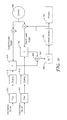
The error detection system of FIG. 7 may be expanded to include feedback that corrects the web movement signal based on the web position error signal. FIG. 8 illustrates the feedback system. As previously described in connection with FIG. 7 , a sensor module 810 senses one of more fiducials on the web and generates fiducial sensor signals. An encoder 820 on a web roller 830 generates one or more signals 821 related to web movement. The fiducial sensor signals 811 and the encoder signals 821 are input to a phase detector 840 which determines the difference in phase between the fiducial sensor signals 811 and the encoder signals 821. The phase detector 840 outputs a web error signal 850 based on the phase difference.
The error signal 850 can be used to improve the accuracy of the encoder signals 821. FIG. 8 illustrates a closed loop feedback circuit that can be used to adjust the encoder signals 821 so that the encoder signals 821 are synchronized with the fiducial signals 811. Feedback control circuitry 860, such as a proportional-integral (PI) controller or a proportional integral-differential (PID) controller generates a feedback signal 861 that is summed with the output from the encoder 830. The output from the summer provides an adjusted web position signal 825. The adjusted web position signal 825 is, in effect, a web encoder signal.
The adjusted web position signal 825 provides enhanced web position determination at least in part because the adjusted web position signal 825 is “cleaner” (less noisy) than the sensed fiducial signals 811. The feedback approach described in FIG. 8 allows the use of sensed fiducials on the web to modify the encoder signal so that changes in the web, such as stretching, shrinking, and/or other distortions, are detected and the web position is corrected relative to the expected distance along the longitudinal web axis. The adjusted web position signal may be used to control various fabrication processes, such as ink jet printing, photolithographic patterning, and/or other fabrication processes.
The multiplication circuitry 940, 942 calculates the product of the sine sensor signal and the cosine encoder signal and the product of the cosine sensor signal and the sine encoder signal. Based on the trigonometric identity, the sine of the phase difference sin(u±v) is calculated as follows:
sin(u±v)=sin(u)cos(v)∓cos(u)sin(v)Equation 1
sin(u±v)=sin(u)cos(v)∓cos(u)sin(v)
where sin(u) is the sine sensor signal; cos(v) is the cosine movement signal; cos(u) is the cosine fiducial signal; and sin(v) is the sine movement signal. The products sin(u) cos(v) and cos(u) sin(v) are input to the summation block 960. The output 961 of the summation block 960 is the sine of the phase error between the fiducial sensor signals and the encoder signals. As illustrated in FIGS. 7 and 8 , either one sinusoidal signal may be used, however, using both sine and cosine signals enhances accuracy and direction tracking. Periodic signals other than sinusoids may alternatively be used.
Web movement signals are generated 1020 based on web movement. As previously discussed, an encoder used to track web movement can provide the web movement signals. The phase difference between the fiducial sensor signals and the web movement signals is calculated 1025. An error signal is generated 1030 based on the phase difference. In one optional process, the error signal may be used to adjust 1035 the encoder signals. The web position can be determined 1040 based on the adjusted encoder signals. As another optional process, the error signal may be used 1050 to control other aspects of a fabrication process, such as web speed. In some applications, both optional processes illustrated in FIG. 10 are implemented.
Phase locking to determine an adjusted web position as described in connection with FIGS. 7-10 , for example, can be used to provide highly accurate web positioning over a number of periodic cycles of the fiducial sensor signals. However, in some implementations, there is little advantage in maintaining position adjustment over long distances relative to the periodic fiducial signals. The large majority of patterns that are formed on a web may be relatively small scale. For example, a display screen of about 20 inches may be fabricated using web position sensing techniques as described herein. For a 20 inch display screen, the web pattern can be readjusted every 24 inches or so.
The readjustment of the web pattern can be accomplished based on discrete fiducial marks (zero marks) disposed on the web which are used in conjunction with the continuous fiducial marks. The discrete marks are used by substrate position circuitry to determine an absolute web position corresponding to the start of a pattern and the continuous fiducials are used to determine web position within the pattern area. FIG. 11 illustrates a portion of a web 1100 having a continuous, periodic fiducial 1111 and zero marks 1112, 1113 arranged at repeatable intervals. The interval between the zero marks may be selected based on the size of the pattern being fabricated. For example, if a circuit that is 6 inches long is being patterned on the web, the zero marks may be disposed at 8 inch intervals along the web.
As the web position is being tracked by the substrate position circuitry, a secondary sensor identifies the passing of a zero mark 1112, 1113. The output 1150 of the secondary sensor is illustrated in FIG. 11 . For example, the detection of a zero mark may generate a pulse 1152, 1153 which is used to identify the starting point for a pattern. Sensing a zero mark initiates a calculation by the substrate position circuitry to identify the most recent zero crossing of the adjusted web position signal 1160. Zero crossing 1162 is identified as the most recent zero crossing for zero mark 1112. Zero crossing 1163 is identified as the most recent zero crossing for zero mark 1113. Note that the adjusted web position signal in this example is a sinusoid and has two zero crossings per cycle. As long as the zero mark 1112. 1113 is detected within a single cycle of the sinusoidal signal 1160, the correct last zero crossing 1162, 1163 of the adjusted web position signal 1160 will be accurately determined.
The embodiments described herein involving continuous fiducial marks provide for continuous tracking of the longitudinal position of a moving web. Simple approaches may be used to apply the web fiducials to general purpose webs such as webs made of paper, fiber, woven or nonwoven material. The webs may comprise polyester, polycarbonate, PET, or other polymeric webs. The redundancy available through the use of sine and cosine marks provides high noise immunity and allows accurate web positioning. The approaches are particularly useful when used in conjunction with flexible webs.
The foregoing description of the various embodiments of the invention has been presented for the purposes of illustration and description. It is not intended to be exhaustive or to limit the invention to the precise form disclosed. Many modifications and variations are possible in light of the above teaching. It is intended that the scope of the invention be limited not by this detailed description, but rather by the claims appended hereto.
Claims (11)
1. A system, comprising:
a sensor module configured to sense one or more fiducials disposed along a longitudinal axis of a substrate and to generate one or more continuous, periodic fiducial sensor signals based on the fiducials;
a signal generator configured to generate one or more continuous, periodic movement signals based on movement of the substrate, the movement signals representing an estimated position of the substrate; and
a phase detector configured to determine a phase difference between the fiducial sensor signals and the movement signals and to generate an error signal based on the phase difference, the error signal representing a substrate position error of the estimated position of the substrate.
2. The system of claim 1 , wherein:
the substrate comprises an elongated, flexible web disposed on a rotating drum; and
the signal generator comprises an encoder configured to detect rotation of the drum.
3. The system of claim 1 , wherein the one or more fiducials comprise two substantially continuous, periodic fiducials that are out of phase with each other.
4. The system of claim 1 , wherein the fiducials comprise sine and cosine fiducials.
5. The system of claim 1 , further comprising feedback circuitry configured to adjust the movement signals based on the error signal so as to correct the substrate position error.
6. The system of claim 5 , further comprising:
a fabrication system configured to fabricate articles on the substrate; and
control circuitry configured to control the fabrication system using the adjusted movement signals.
7. The system of claim 5 , further comprising substrate position circuitry configured to determine substrate position along the longitudinal axis based on the adjusted movement signals.
8. The system of claim 7 , wherein:
the one or more fiducials comprise one or more substantially continuous, periodic fiducials;
the sensor module is configured to detect zero crossings of the periodic fiducials; and
the substrate position circuitry is configured to make absolute position determinations based on the detected zero crossings.
9. The system of claim 7 , wherein:
the sensor module is configured to detect a series of discrete fiducials arranged along the longitudinal axis of the substrate; and
the substrate position circuitry is configured to initiate identification of the zero crossings based on detection of the discrete fiducial marks.
10. The system of claim 7 , wherein:
the sensor module is further configured to sense a reference fiducial disposed along the longitudinal axis of the substrate; and
the substrate position circuitry is configured to determine a substrate position along a lateral axis of the substrate based on a distance between the reference fiducial and the one or more fiducials.
11. A system, comprising:
a sensor module configured to sense one or more fiducials disposed along a longitudinal axis of a substrate and to generate one or more continuous, periodic sensor signals based on the fiducials;
a signal generator configured to generate one or more continuous, periodic signals based on movement of the substrate;
a phase detector configured to determine a phase difference between the sensor signals and the movement signals and to generate an error signal based on the phase difference;
feedback circuitry configured to adjust the movement signals based on the error signal; and substrate position circuitry configured to determine substrate position along the longitudinal axis based on the adjusted movement sensor signals, wherein:
the sensor module is further configured to sense a reference fiducial disposed along the longitudinal axis of the substrate; and the substrate position circuitry is configured to determine an amplitude of the one or more fiducials based on the reference fiducial.
Priority Applications (1)
| Application Number | Priority Date | Filing Date | Title |
|---|---|---|---|
| US14/469,662 US9296583B2 (en) | 2008-12-29 | 2014-08-27 | Phase-locked web position signal using web fiducials |
Applications Claiming Priority (4)
| Application Number | Priority Date | Filing Date | Title |
|---|---|---|---|
| US14112808P | 2008-12-29 | 2008-12-29 | |
| PCT/US2009/066945 WO2010077592A2 (en) | 2008-12-29 | 2009-12-07 | Phase-locked web position signal using web fiducials |
| US201113130592A | 2011-05-23 | 2011-05-23 | |
| US14/469,662 US9296583B2 (en) | 2008-12-29 | 2014-08-27 | Phase-locked web position signal using web fiducials |
Related Parent Applications (2)
| Application Number | Title | Priority Date | Filing Date |
|---|---|---|---|
| US13/130,592 Division US8847185B2 (en) | 2008-12-29 | 2009-12-07 | Phase-locked web position signal using web fiducials |
| PCT/US2009/066945 Division WO2010077592A2 (en) | 2008-12-29 | 2009-12-07 | Phase-locked web position signal using web fiducials |
Publications (2)
| Publication Number | Publication Date |
|---|---|
| US20140368185A1 US20140368185A1 (en) | 2014-12-18 |
| US9296583B2 true US9296583B2 (en) | 2016-03-29 |
Family
ID=42310482
Family Applications (2)
| Application Number | Title | Priority Date | Filing Date |
|---|---|---|---|
| US13/130,592 Expired - Fee Related US8847185B2 (en) | 2008-12-29 | 2009-12-07 | Phase-locked web position signal using web fiducials |
| US14/469,662 Active US9296583B2 (en) | 2008-12-29 | 2014-08-27 | Phase-locked web position signal using web fiducials |
Family Applications Before (1)
| Application Number | Title | Priority Date | Filing Date |
|---|---|---|---|
| US13/130,592 Expired - Fee Related US8847185B2 (en) | 2008-12-29 | 2009-12-07 | Phase-locked web position signal using web fiducials |
Country Status (8)
| Country | Link |
|---|---|
| US (2) | US8847185B2 (en) |
| EP (1) | EP2380067B1 (en) |
| JP (1) | JP5592397B2 (en) |
| KR (1) | KR101667071B1 (en) |
| CN (1) | CN102317882B (en) |
| BR (1) | BRPI0918689A2 (en) |
| SG (1) | SG172349A1 (en) |
| WO (1) | WO2010077592A2 (en) |
Cited By (1)
| Publication number | Priority date | Publication date | Assignee | Title |
|---|---|---|---|---|
| WO2018106489A1 (en) | 2016-12-07 | 2018-06-14 | 3M Innovative Properties Company | Methods of passivating adhesives |
Families Citing this family (19)
| Publication number | Priority date | Publication date | Assignee | Title |
|---|---|---|---|---|
| US9745162B2 (en) | 2011-12-15 | 2017-08-29 | 3M Innovative Properties Company | Apparatus for guiding a moving web |
| US8870331B2 (en) | 2012-06-29 | 2014-10-28 | Xerox Corporation | System and method for process direction alignment of first and second side printed images |
| US9817257B2 (en) | 2012-12-06 | 2017-11-14 | 3M Innovative Properties Company | Discrete coating of liquid on a liquid-coated substrate and use in forming laminates |
| US9738816B2 (en) | 2012-12-06 | 2017-08-22 | 3M Innovative Properties Company | Precision coating of viscous liquids and use in forming laminates |
| WO2014099507A1 (en) | 2012-12-20 | 2014-06-26 | 3M Innovative Properties Company | Printing of multiple inks to achieve precision registration during subsequent processing |
| JP6457528B2 (en) | 2013-08-28 | 2019-01-23 | スリーエム イノベイティブ プロパティズ カンパニー | Electronic assembly with fiducial marks for accurate alignment during subsequent processing steps |
| DE102014203329A1 (en) * | 2014-02-25 | 2015-08-27 | Robert Bosch Gmbh | Method and system for producing a grinding tool |
| US20150239231A1 (en) * | 2014-02-27 | 2015-08-27 | Eastman Kodak Company | Method for reducing artifacts using tension control |
| US20150345996A1 (en) * | 2014-05-29 | 2015-12-03 | Corning Incorporated | Apparatuses and methods for measuring an angle between a web of material and a conveyance direction |
| US20150344347A1 (en) * | 2014-05-29 | 2015-12-03 | Corning Incorporated | Apparatuses for steering flexible glass webs and methods for using the same |
| CN109353136B (en) * | 2014-06-20 | 2020-08-04 | 3M创新有限公司 | Printing of multiple inks to achieve accurate registration during subsequent processing |
| US9557374B2 (en) * | 2014-10-08 | 2017-01-31 | Eastman Kodak Company | Vision-guided alignment system |
| US9581640B2 (en) * | 2014-10-08 | 2017-02-28 | Eastman Kodak Company | Vision-guided alignment method |
| CN107592878A (en) | 2015-05-05 | 2018-01-16 | 3M创新有限公司 | The optically transparent adhesive of Warm Melt and its purposes for display module |
| JP6218793B2 (en) * | 2015-11-18 | 2017-10-25 | 株式会社Pfu | Document conveying apparatus, determination method, and control program |
| CA2976640C (en) * | 2016-08-17 | 2022-09-06 | Les Emballages Trium Inc. | Process for manufacturing bags for packaging items, and bag produced therefrom |
| DE102016012500A1 (en) * | 2016-10-19 | 2018-04-19 | Texmag Gmbh Vertriebsgesellschaft | Method and device for detecting the position of a moving web |
| WO2019082033A1 (en) | 2017-10-24 | 2019-05-02 | 3M Innovative Properties Company | Method and apparatus for generating fiducial via die cutting |
| JP6985136B2 (en) | 2017-12-27 | 2021-12-22 | 株式会社Screenホールディングス | Base material processing equipment and base material processing method |
Citations (98)
| Publication number | Priority date | Publication date | Assignee | Title |
|---|---|---|---|---|
| US1898723A (en) | 1930-05-15 | 1933-02-21 | Package Machinery Co | Method and apparatus for registering printed webs of paper |
| US3570735A (en) | 1968-11-18 | 1971-03-16 | Gpe Controls Inc | Method and apparatus of guiding moving webs |
| US3615048A (en) | 1969-04-03 | 1971-10-26 | Martin Automatic Inc | Apparatus for adjusting the lateral position of a continuous moving web |
| US3667031A (en) | 1970-08-18 | 1972-05-30 | Massachusetts Inst Technology | Phase-locked resolver tracking system |
| US4010463A (en) | 1975-04-21 | 1977-03-01 | The United States Of America As Represented By The Secretary Of The Air Force | Phase locked loop resolver to digital converter |
| US4021031A (en) | 1975-12-08 | 1977-05-03 | Butler Automatic, Inc. | Web alignment system |
| US4049213A (en) | 1975-05-12 | 1977-09-20 | Veb Polygraph Leipzig Kombinat Fur Polygraphische Maschinen Und Ausrustungen | Automatic regulation of the position of the lateral edge of a travelling web |
| GB2065871A (en) | 1979-12-17 | 1981-07-01 | Crosfield Electronics Ltd | Web register control |
| US4284221A (en) | 1978-11-30 | 1981-08-18 | Agfa-Gevaert Aktiengesellschaft | Apparatus for breaking weakened portions of running webs or the like |
| US4363271A (en) | 1979-05-17 | 1982-12-14 | Armstrong World Industries, Inc. | Pattern registration control bars |
| US4401893A (en) | 1981-07-29 | 1983-08-30 | Intec Corporation | Method and apparatus for optically inspecting a moving web of glass |
| US4485982A (en) | 1982-11-24 | 1984-12-04 | Xerox Corporation | Web tracking system |
| US4529922A (en) | 1982-11-15 | 1985-07-16 | Toshiba Kikai Kabushiki Kaisha | Resolver-type rotational positioning arrangement |
| US4532430A (en) | 1980-02-19 | 1985-07-30 | Erwin Sick Gmbh Optik-Elektronik | Fault detection apparatus for material webs |
| US4569584A (en) | 1982-11-24 | 1986-02-11 | Xerox Corporation | Color electrographic recording apparatus |
| US4610739A (en) | 1984-11-02 | 1986-09-09 | Adolph Coors Company | Method and device for providing longitudinal and lateral stretch control in laminated webs |
| JPS62111860A (en) | 1985-11-08 | 1987-05-22 | Matsushita Graphic Commun Syst Inc | Device for detecting position of running sheet |
| US4697485A (en) | 1986-04-16 | 1987-10-06 | Preco Industries, Inc. | Die press having 3-axis registration system operable during material advancement |
| US4731542A (en) | 1986-09-11 | 1988-03-15 | Synergy Computer Graphics | System and method for activating an operating element with respect to a moving substrate |
| US4734868A (en) | 1986-07-21 | 1988-03-29 | Vfn Technology Inc. | Precision paper transport system |
| GB2195179A (en) | 1986-09-11 | 1988-03-30 | Synergy Computer Graphics | Registration system for a moving substrate |
| US4808832A (en) | 1986-09-11 | 1989-02-28 | Synergy Computer Graphics Corp. | Registration system for a moving substrate |
| US4893135A (en) | 1988-09-23 | 1990-01-09 | Eastman Kodak Company | Laser printer with position registration enhancement |
| JPH0237963A (en) | 1988-04-28 | 1990-02-07 | Toshiba Corp | Electrical heating member |
| US4924266A (en) | 1987-05-19 | 1990-05-08 | Asahi Kogaku Kogyo K.K. | Printer for continuous form |
| US4945252A (en) | 1980-07-07 | 1990-07-31 | Automated Packaging Systems, Inc. | Continuous web registration |
| JPH0510725A (en) | 1991-07-05 | 1993-01-19 | Kuwabara Yasunaga | Metal web's position detecting method |
| US5300961A (en) | 1991-12-16 | 1994-04-05 | Xerox Corporation | Method and apparatus for aligning multiple print bars in a single pass system |
| US5355154A (en) | 1992-12-23 | 1994-10-11 | Xerox Corporation | Electronic color printers multiple-pass image self-registration |
| US5384592A (en) | 1992-11-16 | 1995-01-24 | Xerox Corporation | Method and apparatus for tandem color registration control |
| JPH07181032A (en) | 1993-12-21 | 1995-07-18 | Isowa Corp | Sheet running length correction method for sheet running system |
| US5450116A (en) | 1993-09-14 | 1995-09-12 | P-M Acquisition Corp. | Apparatus for generating a spreading information tape |
| EP0680829A2 (en) | 1994-05-03 | 1995-11-08 | Hewlett-Packard Company | Optical control system for media handling assemblies in printers |
| US5579092A (en) | 1994-03-14 | 1996-11-26 | Oki Electric Industry Co., Ltd. | Color printer correctable positional errors in respective printing mechanisms |
| US5667123A (en) | 1992-12-25 | 1997-09-16 | Ishida Co., Ltd. | Apparatus for correcting zigzag motion of an elongated traveling web |
| EP0838665A1 (en) | 1996-10-28 | 1998-04-29 | Mitutoyo Corporation | Optical displacement detecting apparatus |
| US5768776A (en) | 1993-12-17 | 1998-06-23 | Hewlett-Packard Company | Method for forming a controlled impedance flex circuit |
| US5778724A (en) | 1995-09-07 | 1998-07-14 | Minnesota Mining & Mfg | Method and device for monitoring web bagginess |
| US5859707A (en) | 1996-02-13 | 1999-01-12 | Nikon Corporation | Position detection apparatus and aligner comprising same |
| US5870204A (en) | 1996-03-15 | 1999-02-09 | Sony Corporation | Adaptive lighting control apparatus for illuminating a variable-speed web for inspection |
| US5875023A (en) | 1997-01-31 | 1999-02-23 | International Business Machines Corporation | Dual-sided expose mechanism for web product |
| DE19754776A1 (en) | 1997-11-28 | 1999-06-02 | Ralf Dr Paugstadt | Security marking system e.g. to prevent fraud, counterfeiting and pilfering |
| JPH11167165A (en) | 1997-12-03 | 1999-06-22 | Fuji Photo Film Co Ltd | Method for aligning frame detection part of microfilm retrieving device and microfilm for alignment |
| US5931097A (en) | 1995-05-08 | 1999-08-03 | Flex Products, Inc. | Laser imageable lithographic printing member |
| US6053107A (en) | 1999-01-13 | 2000-04-25 | Paper Converting Machine Co. | Method and apparatus for registering a pre-printed web on a printing press |
| US6056180A (en) | 1994-11-04 | 2000-05-02 | Roll Systems, Inc. | Method and apparatus for pinless feeding of web to a utilization device |
| US6087655A (en) | 1998-05-19 | 2000-07-11 | Kobrin; Boris | Fiber grating encoders and methods for fabricating the same |
| US6164201A (en) | 1998-09-11 | 2000-12-26 | Heidelberger Druckmachinen Ag | Method and apparatus for web steering |
| US6199480B1 (en) | 1992-06-06 | 2001-03-13 | Heideiberger Druckmaschinen | Arrangement for determining register deviations of a multicolor rotary printing machine |
| US6206263B1 (en) | 1999-05-13 | 2001-03-27 | Gerber Scientific Products, Inc. | Material advance tracking system |
| US6273313B1 (en) | 1999-06-02 | 2001-08-14 | The Proctor & Gamble Company | Process and apparatus for controlling the registration of converting operations with prints on a web |
| CN2447719Y (en) | 2000-10-30 | 2001-09-12 | 中南大学 | Linear displacement transducer |
| US6322236B1 (en) | 1999-02-09 | 2001-11-27 | 3M Innovative Properties Company | Optical film with defect-reducing surface and method for making same |
| US6336019B2 (en) | 1999-11-29 | 2002-01-01 | Xerox Corporation | Surface position and velocity measurement for photoreceptor belt |
| US20020018220A1 (en) | 2000-08-07 | 2002-02-14 | Mitutoyo Corporation | Optical displacement-measuring apparatus |
| US6375870B1 (en) | 1998-11-17 | 2002-04-23 | Corning Incorporated | Replicating a nanoscale pattern |
| US6396073B1 (en) | 1995-12-19 | 2002-05-28 | Monarch Marking Systems, Inc. | Web of record members |
| EP1235054A2 (en) | 2001-02-20 | 2002-08-28 | Canon Kabushiki Kaisha | Reflection scale and displacement measurement apparatus using the same |
| US20020121131A1 (en) | 1999-02-05 | 2002-09-05 | Vladimir Mancevski | System and method of multi-dimensional force sensing for scanning probe microscopy |
| US6495214B1 (en) | 1997-05-21 | 2002-12-17 | Emtec Magnetics Gmbh | Method of producing a film or a layer with a surface structure on both sides |
| US6505906B1 (en) | 2001-12-28 | 2003-01-14 | Phogenix Imaging, Llc | Method of exercising nozzles of an inkjet printer and article |
| US6521905B1 (en) | 1999-09-22 | 2003-02-18 | Nexpress Solutions Llc | Method and device for detecting the position of a transparent moving conveyor belt |
| US6647128B1 (en) | 1993-11-18 | 2003-11-11 | Digimarc Corporation | Method for monitoring internet dissemination of image, video, and/or audio files |
| US20030218125A1 (en) | 2002-05-21 | 2003-11-27 | Masahiko Igaki | Sensor using roof mirror/roof prism array scale, and apparatus equipped with the sensor |
| US20040022557A1 (en) | 2002-03-22 | 2004-02-05 | Koichi Kudo | Drive control device and image forming apparatus including the same |
| US20040197443A1 (en) | 2001-11-02 | 2004-10-07 | Paolo Scarabelli | Sheet material for producing packages of food products, and packages made of such material |
| US20040227644A1 (en) | 2003-05-15 | 2004-11-18 | Yingjie Lin | Linear position sensor |
| US20040240513A1 (en) | 2003-05-30 | 2004-12-02 | Asml Holding N.V. | Stage with thermal expansion compensation |
| US20040262505A1 (en) | 2003-06-30 | 2004-12-30 | Akio Atsuta | Optical encoder |
| JP2005049237A (en) | 2003-07-29 | 2005-02-24 | Kao Corp | Measuring method and measuring device of continuing sheet |
| JP2005178962A (en) | 2003-12-18 | 2005-07-07 | Murata Mfg Co Ltd | Position recognition method and position recognition device for object to be conveyed |
| US20050218237A1 (en) | 2004-04-02 | 2005-10-06 | Paul Lapstun And Kia Silverbrook | Surface having disposed therein or thereon coded data |
| US20050232475A1 (en) | 2004-04-19 | 2005-10-20 | 3M Innovative Properties Company | Apparatus and method for the automated marking of defects on webs of material |
| US20050263689A1 (en) | 2004-05-26 | 2005-12-01 | Akio Atsuta | Optical encoder |
| US20050274880A1 (en) | 2004-06-15 | 2005-12-15 | Canon Kabushiki Kaisha | Optical encoder |
| US20060174992A1 (en) | 2005-02-09 | 2006-08-10 | Brost Randolph C | Web stabilization for accurate pattern registration |
| US20060210714A1 (en) | 2005-03-09 | 2006-09-21 | Huizinga John S | Apparatus and method for producing two-sided patterned web in registration |
| WO2006107057A1 (en) | 2005-03-30 | 2006-10-12 | Nissha Printing Co., Ltd. | Molding apparatus and molding method using a transfer film |
| US7121496B2 (en) | 2003-10-23 | 2006-10-17 | Hewlett-Packard Development Company, L.P. | Method and system for correcting web deformation during a roll-to-roll process |
| US7133630B2 (en) | 2003-07-29 | 2006-11-07 | Ricoh Company, Ltd. | Belt device, image forming apparatus, and method to control belt speed |
| EP1722021A1 (en) | 2005-05-11 | 2006-11-15 | Dürkopp Adler Aktiengesellschaft | Button hole sewing machine |
| WO2007027757A2 (en) | 2005-08-30 | 2007-03-08 | Georgia Tech Research Corporation | Direct write nanolithography using heated tip |
| US20070099396A1 (en) | 2005-10-27 | 2007-05-03 | Seiko Epson Corporation | Method of forming pattern, film structure, electrooptical device and electronic equipment |
| US20070138153A1 (en) | 2005-12-20 | 2007-06-21 | Redman Dean E | Wide web laser ablation |
| US7296717B2 (en) | 2003-11-21 | 2007-11-20 | 3M Innovative Properties Company | Method and apparatus for controlling a moving web |
| US20080039718A1 (en) | 2006-08-12 | 2008-02-14 | Philometron | Platform for detection of tissue structure change |
| US20080073493A1 (en) | 2006-09-22 | 2008-03-27 | Canon Kabushiki Kaisha | Origin detection method for optical encoder |
| CN101191784A (en) | 2006-11-27 | 2008-06-04 | 罗伯特·博世有限公司 | Sensor unit of a gas sensor for determining physical characteristic of measured gas |
| WO2008088650A1 (en) | 2007-01-11 | 2008-07-24 | 3M Innovative Properties Company | Web longitudinal position sensor |
| US20080219741A1 (en) | 2007-03-07 | 2008-09-11 | Mcnestry Martin | Tape drive |
| US7526230B2 (en) | 2004-07-02 | 2009-04-28 | Ricoh Company, Ltd. | Mark sensing device, turnable body driving device and image forming apparatus |
| US7560718B2 (en) | 2005-07-01 | 2009-07-14 | Texmag GmbH Vertriebsgesellschaft. | Method for sensing a marking on a running web of material |
| US7573580B2 (en) | 2003-11-17 | 2009-08-11 | Asml Holding N.V. | Optical position measuring system and method using a low coherence light source |
| WO2010077719A2 (en) | 2008-12-30 | 2010-07-08 | 3M Innovative Properties Company | Apparatus and method for making fiducials on a substrate |
| US20100187277A1 (en) | 2007-06-19 | 2010-07-29 | Carlson Daniel H | Systems and methods for indicating the position of a web |
| US20100188668A1 (en) | 2007-06-19 | 2010-07-29 | 3M Innovative Properties Company | Total internal reflection displacement scale |
| US20100196607A1 (en) | 2007-06-19 | 2010-08-05 | 3M Innovative Properties Company | Systems and methods for fabricating displacement scales |
| US7826041B2 (en) | 2008-03-05 | 2010-11-02 | Taiyo Electric Industry Co., Ltd. | Register mark detection apparatus |
Family Cites Families (8)
| Publication number | Priority date | Publication date | Assignee | Title |
|---|---|---|---|---|
| CA1127259A (en) | 1978-10-19 | 1982-07-06 | Jean Burtin | Method and device for inspecting a moving sheet material for streaklike defects |
| US4618518A (en) | 1984-08-10 | 1986-10-21 | Amerace Corporation | Retroreflective sheeting and methods for making same |
| JPS6372558U (en) * | 1986-10-29 | 1988-05-14 | ||
| JPH01141308A (en) * | 1987-11-27 | 1989-06-02 | Dainippon Screen Mfg Co Ltd | Measuring instrument using encoder |
| DE58901190D1 (en) | 1989-04-12 | 1992-05-21 | Landis & Gyr Betriebs Ag | ARRANGEMENT FOR MEASURING A TRACK DIFFERENCE OF A MOVABLE FILM COVER. |
| US7317980B2 (en) | 2002-07-30 | 2008-01-08 | Adivics Co., Ltd. | Automatic brake device for controlling movement of vehicle in direction opposite to intended direction of movement of driver |
| JP4755400B2 (en) | 2003-08-29 | 2011-08-24 | 株式会社リコー | Endless moving member driving device, image forming apparatus, photoreceptor driving device, and endless moving member deterioration warning method |
| US7943097B2 (en) * | 2007-01-09 | 2011-05-17 | Catalytic Solutions, Inc. | Reactor system for reducing NOx emissions from boilers |
-
2009
- 2009-12-07 SG SG2011046190A patent/SG172349A1/en unknown
- 2009-12-07 US US13/130,592 patent/US8847185B2/en not_active Expired - Fee Related
- 2009-12-07 WO PCT/US2009/066945 patent/WO2010077592A2/en active Application Filing
- 2009-12-07 JP JP2011543545A patent/JP5592397B2/en not_active Expired - Fee Related
- 2009-12-07 BR BRPI0918689A patent/BRPI0918689A2/en not_active IP Right Cessation
- 2009-12-07 CN CN200980156499.2A patent/CN102317882B/en not_active Expired - Fee Related
- 2009-12-07 KR KR1020117017596A patent/KR101667071B1/en active IP Right Grant
- 2009-12-07 EP EP09836677.6A patent/EP2380067B1/en not_active Not-in-force
-
2014
- 2014-08-27 US US14/469,662 patent/US9296583B2/en active Active
Patent Citations (102)
| Publication number | Priority date | Publication date | Assignee | Title |
|---|---|---|---|---|
| US1898723A (en) | 1930-05-15 | 1933-02-21 | Package Machinery Co | Method and apparatus for registering printed webs of paper |
| US3570735A (en) | 1968-11-18 | 1971-03-16 | Gpe Controls Inc | Method and apparatus of guiding moving webs |
| US3615048A (en) | 1969-04-03 | 1971-10-26 | Martin Automatic Inc | Apparatus for adjusting the lateral position of a continuous moving web |
| US3667031A (en) | 1970-08-18 | 1972-05-30 | Massachusetts Inst Technology | Phase-locked resolver tracking system |
| US4010463A (en) | 1975-04-21 | 1977-03-01 | The United States Of America As Represented By The Secretary Of The Air Force | Phase locked loop resolver to digital converter |
| US4049213A (en) | 1975-05-12 | 1977-09-20 | Veb Polygraph Leipzig Kombinat Fur Polygraphische Maschinen Und Ausrustungen | Automatic regulation of the position of the lateral edge of a travelling web |
| US4021031A (en) | 1975-12-08 | 1977-05-03 | Butler Automatic, Inc. | Web alignment system |
| US4284221A (en) | 1978-11-30 | 1981-08-18 | Agfa-Gevaert Aktiengesellschaft | Apparatus for breaking weakened portions of running webs or the like |
| US4363271A (en) | 1979-05-17 | 1982-12-14 | Armstrong World Industries, Inc. | Pattern registration control bars |
| GB2065871A (en) | 1979-12-17 | 1981-07-01 | Crosfield Electronics Ltd | Web register control |
| US4532430A (en) | 1980-02-19 | 1985-07-30 | Erwin Sick Gmbh Optik-Elektronik | Fault detection apparatus for material webs |
| US4945252A (en) | 1980-07-07 | 1990-07-31 | Automated Packaging Systems, Inc. | Continuous web registration |
| US4401893A (en) | 1981-07-29 | 1983-08-30 | Intec Corporation | Method and apparatus for optically inspecting a moving web of glass |
| US4529922A (en) | 1982-11-15 | 1985-07-16 | Toshiba Kikai Kabushiki Kaisha | Resolver-type rotational positioning arrangement |
| US4569584A (en) | 1982-11-24 | 1986-02-11 | Xerox Corporation | Color electrographic recording apparatus |
| US4485982A (en) | 1982-11-24 | 1984-12-04 | Xerox Corporation | Web tracking system |
| US4610739A (en) | 1984-11-02 | 1986-09-09 | Adolph Coors Company | Method and device for providing longitudinal and lateral stretch control in laminated webs |
| JPS62111860A (en) | 1985-11-08 | 1987-05-22 | Matsushita Graphic Commun Syst Inc | Device for detecting position of running sheet |
| US4697485A (en) | 1986-04-16 | 1987-10-06 | Preco Industries, Inc. | Die press having 3-axis registration system operable during material advancement |
| US4734868A (en) | 1986-07-21 | 1988-03-29 | Vfn Technology Inc. | Precision paper transport system |
| US4808832A (en) | 1986-09-11 | 1989-02-28 | Synergy Computer Graphics Corp. | Registration system for a moving substrate |
| GB2195179A (en) | 1986-09-11 | 1988-03-30 | Synergy Computer Graphics | Registration system for a moving substrate |
| US4731542A (en) | 1986-09-11 | 1988-03-15 | Synergy Computer Graphics | System and method for activating an operating element with respect to a moving substrate |
| US4924266A (en) | 1987-05-19 | 1990-05-08 | Asahi Kogaku Kogyo K.K. | Printer for continuous form |
| JPH0237963A (en) | 1988-04-28 | 1990-02-07 | Toshiba Corp | Electrical heating member |
| US4893135A (en) | 1988-09-23 | 1990-01-09 | Eastman Kodak Company | Laser printer with position registration enhancement |
| JPH0510725A (en) | 1991-07-05 | 1993-01-19 | Kuwabara Yasunaga | Metal web's position detecting method |
| US5300961A (en) | 1991-12-16 | 1994-04-05 | Xerox Corporation | Method and apparatus for aligning multiple print bars in a single pass system |
| US6199480B1 (en) | 1992-06-06 | 2001-03-13 | Heideiberger Druckmaschinen | Arrangement for determining register deviations of a multicolor rotary printing machine |
| US5384592A (en) | 1992-11-16 | 1995-01-24 | Xerox Corporation | Method and apparatus for tandem color registration control |
| US5355154A (en) | 1992-12-23 | 1994-10-11 | Xerox Corporation | Electronic color printers multiple-pass image self-registration |
| US5667123A (en) | 1992-12-25 | 1997-09-16 | Ishida Co., Ltd. | Apparatus for correcting zigzag motion of an elongated traveling web |
| US5450116A (en) | 1993-09-14 | 1995-09-12 | P-M Acquisition Corp. | Apparatus for generating a spreading information tape |
| US6647128B1 (en) | 1993-11-18 | 2003-11-11 | Digimarc Corporation | Method for monitoring internet dissemination of image, video, and/or audio files |
| US5768776A (en) | 1993-12-17 | 1998-06-23 | Hewlett-Packard Company | Method for forming a controlled impedance flex circuit |
| JPH07181032A (en) | 1993-12-21 | 1995-07-18 | Isowa Corp | Sheet running length correction method for sheet running system |
| US5579092A (en) | 1994-03-14 | 1996-11-26 | Oki Electric Industry Co., Ltd. | Color printer correctable positional errors in respective printing mechanisms |
| EP0680829A2 (en) | 1994-05-03 | 1995-11-08 | Hewlett-Packard Company | Optical control system for media handling assemblies in printers |
| US6056180A (en) | 1994-11-04 | 2000-05-02 | Roll Systems, Inc. | Method and apparatus for pinless feeding of web to a utilization device |
| US5931097A (en) | 1995-05-08 | 1999-08-03 | Flex Products, Inc. | Laser imageable lithographic printing member |
| US5778724A (en) | 1995-09-07 | 1998-07-14 | Minnesota Mining & Mfg | Method and device for monitoring web bagginess |
| US6396073B1 (en) | 1995-12-19 | 2002-05-28 | Monarch Marking Systems, Inc. | Web of record members |
| US5859707A (en) | 1996-02-13 | 1999-01-12 | Nikon Corporation | Position detection apparatus and aligner comprising same |
| US5870204A (en) | 1996-03-15 | 1999-02-09 | Sony Corporation | Adaptive lighting control apparatus for illuminating a variable-speed web for inspection |
| EP0838665A1 (en) | 1996-10-28 | 1998-04-29 | Mitutoyo Corporation | Optical displacement detecting apparatus |
| US5875023A (en) | 1997-01-31 | 1999-02-23 | International Business Machines Corporation | Dual-sided expose mechanism for web product |
| US6495214B1 (en) | 1997-05-21 | 2002-12-17 | Emtec Magnetics Gmbh | Method of producing a film or a layer with a surface structure on both sides |
| DE19754776A1 (en) | 1997-11-28 | 1999-06-02 | Ralf Dr Paugstadt | Security marking system e.g. to prevent fraud, counterfeiting and pilfering |
| JPH11167165A (en) | 1997-12-03 | 1999-06-22 | Fuji Photo Film Co Ltd | Method for aligning frame detection part of microfilm retrieving device and microfilm for alignment |
| US6087655A (en) | 1998-05-19 | 2000-07-11 | Kobrin; Boris | Fiber grating encoders and methods for fabricating the same |
| US6164201A (en) | 1998-09-11 | 2000-12-26 | Heidelberger Druckmachinen Ag | Method and apparatus for web steering |
| US6375870B1 (en) | 1998-11-17 | 2002-04-23 | Corning Incorporated | Replicating a nanoscale pattern |
| US6053107A (en) | 1999-01-13 | 2000-04-25 | Paper Converting Machine Co. | Method and apparatus for registering a pre-printed web on a printing press |
| US20020121131A1 (en) | 1999-02-05 | 2002-09-05 | Vladimir Mancevski | System and method of multi-dimensional force sensing for scanning probe microscopy |
| US6322236B1 (en) | 1999-02-09 | 2001-11-27 | 3M Innovative Properties Company | Optical film with defect-reducing surface and method for making same |
| US6206263B1 (en) | 1999-05-13 | 2001-03-27 | Gerber Scientific Products, Inc. | Material advance tracking system |
| US6273313B1 (en) | 1999-06-02 | 2001-08-14 | The Proctor & Gamble Company | Process and apparatus for controlling the registration of converting operations with prints on a web |
| US6521905B1 (en) | 1999-09-22 | 2003-02-18 | Nexpress Solutions Llc | Method and device for detecting the position of a transparent moving conveyor belt |
| US6336019B2 (en) | 1999-11-29 | 2002-01-01 | Xerox Corporation | Surface position and velocity measurement for photoreceptor belt |
| US20020018220A1 (en) | 2000-08-07 | 2002-02-14 | Mitutoyo Corporation | Optical displacement-measuring apparatus |
| CN2447719Y (en) | 2000-10-30 | 2001-09-12 | 中南大学 | Linear displacement transducer |
| EP1235054A2 (en) | 2001-02-20 | 2002-08-28 | Canon Kabushiki Kaisha | Reflection scale and displacement measurement apparatus using the same |
| US20020122186A1 (en) | 2001-02-20 | 2002-09-05 | Masahiko Igaki | Reflection scale and displacement measurement apparatus using the same |
| US20040197443A1 (en) | 2001-11-02 | 2004-10-07 | Paolo Scarabelli | Sheet material for producing packages of food products, and packages made of such material |
| US6505906B1 (en) | 2001-12-28 | 2003-01-14 | Phogenix Imaging, Llc | Method of exercising nozzles of an inkjet printer and article |
| US20040022557A1 (en) | 2002-03-22 | 2004-02-05 | Koichi Kudo | Drive control device and image forming apparatus including the same |
| US20030218125A1 (en) | 2002-05-21 | 2003-11-27 | Masahiko Igaki | Sensor using roof mirror/roof prism array scale, and apparatus equipped with the sensor |
| US20040227644A1 (en) | 2003-05-15 | 2004-11-18 | Yingjie Lin | Linear position sensor |
| US20040240513A1 (en) | 2003-05-30 | 2004-12-02 | Asml Holding N.V. | Stage with thermal expansion compensation |
| US20040262505A1 (en) | 2003-06-30 | 2004-12-30 | Akio Atsuta | Optical encoder |
| JP2005049237A (en) | 2003-07-29 | 2005-02-24 | Kao Corp | Measuring method and measuring device of continuing sheet |
| US7133630B2 (en) | 2003-07-29 | 2006-11-07 | Ricoh Company, Ltd. | Belt device, image forming apparatus, and method to control belt speed |
| US7121496B2 (en) | 2003-10-23 | 2006-10-17 | Hewlett-Packard Development Company, L.P. | Method and system for correcting web deformation during a roll-to-roll process |
| US7573580B2 (en) | 2003-11-17 | 2009-08-11 | Asml Holding N.V. | Optical position measuring system and method using a low coherence light source |
| US7296717B2 (en) | 2003-11-21 | 2007-11-20 | 3M Innovative Properties Company | Method and apparatus for controlling a moving web |
| JP2005178962A (en) | 2003-12-18 | 2005-07-07 | Murata Mfg Co Ltd | Position recognition method and position recognition device for object to be conveyed |
| US20050218237A1 (en) | 2004-04-02 | 2005-10-06 | Paul Lapstun And Kia Silverbrook | Surface having disposed therein or thereon coded data |
| US20050232475A1 (en) | 2004-04-19 | 2005-10-20 | 3M Innovative Properties Company | Apparatus and method for the automated marking of defects on webs of material |
| WO2005106104A1 (en) | 2004-04-19 | 2005-11-10 | 3M Innovative Properties Company | Apparatus and method for the automated marking of defects on webs of material |
| US20050263689A1 (en) | 2004-05-26 | 2005-12-01 | Akio Atsuta | Optical encoder |
| US20050274880A1 (en) | 2004-06-15 | 2005-12-15 | Canon Kabushiki Kaisha | Optical encoder |
| US7526230B2 (en) | 2004-07-02 | 2009-04-28 | Ricoh Company, Ltd. | Mark sensing device, turnable body driving device and image forming apparatus |
| US20060174992A1 (en) | 2005-02-09 | 2006-08-10 | Brost Randolph C | Web stabilization for accurate pattern registration |
| US20060210714A1 (en) | 2005-03-09 | 2006-09-21 | Huizinga John S | Apparatus and method for producing two-sided patterned web in registration |
| WO2006107057A1 (en) | 2005-03-30 | 2006-10-12 | Nissha Printing Co., Ltd. | Molding apparatus and molding method using a transfer film |
| EP1722021A1 (en) | 2005-05-11 | 2006-11-15 | Dürkopp Adler Aktiengesellschaft | Button hole sewing machine |
| US7560718B2 (en) | 2005-07-01 | 2009-07-14 | Texmag GmbH Vertriebsgesellschaft. | Method for sensing a marking on a running web of material |
| WO2007027757A2 (en) | 2005-08-30 | 2007-03-08 | Georgia Tech Research Corporation | Direct write nanolithography using heated tip |
| US20070099396A1 (en) | 2005-10-27 | 2007-05-03 | Seiko Epson Corporation | Method of forming pattern, film structure, electrooptical device and electronic equipment |
| US20070138153A1 (en) | 2005-12-20 | 2007-06-21 | Redman Dean E | Wide web laser ablation |
| US20080039718A1 (en) | 2006-08-12 | 2008-02-14 | Philometron | Platform for detection of tissue structure change |
| US20080073493A1 (en) | 2006-09-22 | 2008-03-27 | Canon Kabushiki Kaisha | Origin detection method for optical encoder |
| CN101191784A (en) | 2006-11-27 | 2008-06-04 | 罗伯特·博世有限公司 | Sensor unit of a gas sensor for determining physical characteristic of measured gas |
| WO2008088650A1 (en) | 2007-01-11 | 2008-07-24 | 3M Innovative Properties Company | Web longitudinal position sensor |
| US20100097462A1 (en) | 2007-01-11 | 2010-04-22 | Carlson Daniel H | Web longitudinal position sensor |
| US20080219741A1 (en) | 2007-03-07 | 2008-09-11 | Mcnestry Martin | Tape drive |
| US20100187277A1 (en) | 2007-06-19 | 2010-07-29 | Carlson Daniel H | Systems and methods for indicating the position of a web |
| US20100188668A1 (en) | 2007-06-19 | 2010-07-29 | 3M Innovative Properties Company | Total internal reflection displacement scale |
| US20100196607A1 (en) | 2007-06-19 | 2010-08-05 | 3M Innovative Properties Company | Systems and methods for fabricating displacement scales |
| US8405831B2 (en) | 2007-06-19 | 2013-03-26 | 3M Innovative Properties Company | Systems and methods for indicating the position of a web |
| US7826041B2 (en) | 2008-03-05 | 2010-11-02 | Taiyo Electric Industry Co., Ltd. | Register mark detection apparatus |
| WO2010077719A2 (en) | 2008-12-30 | 2010-07-08 | 3M Innovative Properties Company | Apparatus and method for making fiducials on a substrate |
Cited By (2)
| Publication number | Priority date | Publication date | Assignee | Title |
|---|---|---|---|---|
| WO2018106489A1 (en) | 2016-12-07 | 2018-06-14 | 3M Innovative Properties Company | Methods of passivating adhesives |
| US11279859B2 (en) | 2016-12-07 | 2022-03-22 | 3M Innovative Properties Company | Methods of passivating adhesives |
Also Published As
| Publication number | Publication date |
|---|---|
| US8847185B2 (en) | 2014-09-30 |
| WO2010077592A2 (en) | 2010-07-08 |
| KR101667071B1 (en) | 2016-10-17 |
| EP2380067A4 (en) | 2018-01-24 |
| JP2012514199A (en) | 2012-06-21 |
| US20110257779A1 (en) | 2011-10-20 |
| EP2380067A2 (en) | 2011-10-26 |
| CN102317882A (en) | 2012-01-11 |
| US20140368185A1 (en) | 2014-12-18 |
| WO2010077592A3 (en) | 2010-10-14 |
| SG172349A1 (en) | 2011-07-28 |
| BRPI0918689A2 (en) | 2016-07-26 |
| EP2380067B1 (en) | 2019-06-26 |
| CN102317882B (en) | 2015-04-22 |
| JP5592397B2 (en) | 2014-09-17 |
| KR20110099055A (en) | 2011-09-05 |
Similar Documents
| Publication | Publication Date | Title |
|---|---|---|
| US9296583B2 (en) | Phase-locked web position signal using web fiducials | |
| US9440812B2 (en) | Web longitudinal position sensor | |
| EP2389478B1 (en) | Apparatus and method for making fiducials on a substrate | |
| US20080011225A1 (en) | Apparatus and methods for continuously depositing a pattern of material onto a substrate | |
| EP0540142B1 (en) | Substrate advance measurement system | |
| US11370233B2 (en) | Base material processing apparatus and base material processing method | |
| CN100596256C (en) | Apparatus and methods for continuously depositing a pattern of material onto a substrate | |
| JP5441618B2 (en) | Movement detection apparatus, movement detection method, and recording apparatus | |
| JP2002273800A (en) | Device for controlling cutting position of traveling sheet | |
| KR101409485B1 (en) | Method for registration mark accuracy in roll-to-roll process | |
| EP4309905A1 (en) | Conveyor belt having magnetic linear encoder readable magnetic markers | |
| JP3049788B2 (en) | Slit framing device | |
| FR2693328A1 (en) | Frequency multiplier synchronization device of a machine equipped with such a multiplier, ink jet printer using such a device. |
Legal Events
| Date | Code | Title | Description |
|---|---|---|---|
| STCF | Information on status: patent grant |
Free format text: PATENTED CASE |
|
| CC | Certificate of correction | ||
| MAFP | Maintenance fee payment |
Free format text: PAYMENT OF MAINTENANCE FEE, 4TH YEAR, LARGE ENTITY (ORIGINAL EVENT CODE: M1551); ENTITY STATUS OF PATENT OWNER: LARGE ENTITY Year of fee payment: 4 |
|
| MAFP | Maintenance fee payment |
Free format text: PAYMENT OF MAINTENANCE FEE, 8TH YEAR, LARGE ENTITY (ORIGINAL EVENT CODE: M1552); ENTITY STATUS OF PATENT OWNER: LARGE ENTITY Year of fee payment: 8 |