US9288836B1 - Electronic bracelet - Google Patents
Electronic bracelet Download PDFInfo
- Publication number
- US9288836B1 US9288836B1 US13/421,041 US201213421041A US9288836B1 US 9288836 B1 US9288836 B1 US 9288836B1 US 201213421041 A US201213421041 A US 201213421041A US 9288836 B1 US9288836 B1 US 9288836B1
- Authority
- US
- United States
- Prior art keywords
- bracelet
- circuit
- nfc
- field communication
- sensor
- Prior art date
- Legal status (The legal status is an assumption and is not a legal conclusion. Google has not performed a legal analysis and makes no representation as to the accuracy of the status listed.)
- Expired - Fee Related, expires
Links
- 238000004891 communication Methods 0.000 claims abstract description 96
- 238000012545 processing Methods 0.000 claims description 28
- 230000033001 locomotion Effects 0.000 claims description 16
- 230000004044 response Effects 0.000 claims description 14
- 238000003860 storage Methods 0.000 claims description 12
- 230000007613 environmental effect Effects 0.000 claims description 11
- 230000036772 blood pressure Effects 0.000 claims description 7
- 239000003086 colorant Substances 0.000 claims description 5
- 230000008707 rearrangement Effects 0.000 claims 1
- 230000006870 function Effects 0.000 description 49
- 238000013461 design Methods 0.000 description 28
- 238000000034 method Methods 0.000 description 19
- 238000010586 diagram Methods 0.000 description 17
- 210000000707 wrist Anatomy 0.000 description 17
- 230000008859 change Effects 0.000 description 13
- 230000009471 action Effects 0.000 description 6
- 230000008901 benefit Effects 0.000 description 5
- 230000006698 induction Effects 0.000 description 5
- 230000015654 memory Effects 0.000 description 5
- 230000005540 biological transmission Effects 0.000 description 4
- 230000036760 body temperature Effects 0.000 description 4
- 230000007480 spreading Effects 0.000 description 4
- 238000003892 spreading Methods 0.000 description 4
- 230000001413 cellular effect Effects 0.000 description 3
- 238000004590 computer program Methods 0.000 description 3
- 230000008569 process Effects 0.000 description 3
- 230000033764 rhythmic process Effects 0.000 description 3
- 230000004913 activation Effects 0.000 description 2
- 239000004020 conductor Substances 0.000 description 2
- 230000008878 coupling Effects 0.000 description 2
- 238000010168 coupling process Methods 0.000 description 2
- 238000005859 coupling reaction Methods 0.000 description 2
- 238000001514 detection method Methods 0.000 description 2
- 239000000428 dust Substances 0.000 description 2
- 238000005516 engineering process Methods 0.000 description 2
- 230000001939 inductive effect Effects 0.000 description 2
- 239000000463 material Substances 0.000 description 2
- 230000036651 mood Effects 0.000 description 2
- 238000010200 validation analysis Methods 0.000 description 2
- 208000030470 Trigger Finger disease Diseases 0.000 description 1
- 230000010267 cellular communication Effects 0.000 description 1
- 239000013078 crystal Substances 0.000 description 1
- 238000013479 data entry Methods 0.000 description 1
- 210000003414 extremity Anatomy 0.000 description 1
- 210000004247 hand Anatomy 0.000 description 1
- 239000004973 liquid crystal related substance Substances 0.000 description 1
- 238000004519 manufacturing process Methods 0.000 description 1
- 238000012986 modification Methods 0.000 description 1
- 230000004048 modification Effects 0.000 description 1
- 208000010125 myocardial infarction Diseases 0.000 description 1
- 230000003287 optical effect Effects 0.000 description 1
- 238000003825 pressing Methods 0.000 description 1
- 230000035485 pulse pressure Effects 0.000 description 1
- 230000000717 retained effect Effects 0.000 description 1
- 230000011664 signaling Effects 0.000 description 1
- 230000000007 visual effect Effects 0.000 description 1
- XLYOFNOQVPJJNP-UHFFFAOYSA-N water Substances O XLYOFNOQVPJJNP-UHFFFAOYSA-N 0.000 description 1
Images


Classifications
-
- H—ELECTRICITY
- H04—ELECTRIC COMMUNICATION TECHNIQUE
- H04W—WIRELESS COMMUNICATION NETWORKS
- H04W84/00—Network topologies
- H04W84/18—Self-organising networks, e.g. ad-hoc networks or sensor networks
-
- A—HUMAN NECESSITIES
- A44—HABERDASHERY; JEWELLERY
- A44C—PERSONAL ADORNMENTS, e.g. JEWELLERY; COINS
- A44C5/00—Bracelets; Wrist-watch straps; Fastenings for bracelets or wrist-watch straps
- A44C5/0007—Bracelets specially adapted for other functions or with means for attaching other articles
-
- A—HUMAN NECESSITIES
- A44—HABERDASHERY; JEWELLERY
- A44C—PERSONAL ADORNMENTS, e.g. JEWELLERY; COINS
- A44C5/00—Bracelets; Wrist-watch straps; Fastenings for bracelets or wrist-watch straps
- A44C5/0084—Bracelets in the form of a ring, band or tube of rigid material
-
- A—HUMAN NECESSITIES
- A44—HABERDASHERY; JEWELLERY
- A44C—PERSONAL ADORNMENTS, e.g. JEWELLERY; COINS
- A44C5/00—Bracelets; Wrist-watch straps; Fastenings for bracelets or wrist-watch straps
- A44C5/02—Link constructions
- A44C5/10—Link constructions not extensible
- A44C5/105—Link constructions not extensible with links made of one piece and linked together by one connecting element
-
- G—PHYSICS
- G06—COMPUTING; CALCULATING OR COUNTING
- G06F—ELECTRIC DIGITAL DATA PROCESSING
- G06F1/00—Details not covered by groups G06F3/00 - G06F13/00 and G06F21/00
- G06F1/16—Constructional details or arrangements
- G06F1/1613—Constructional details or arrangements for portable computers
- G06F1/163—Wearable computers, e.g. on a belt
Definitions
- the present disclosure relates generally to wireless devices, and more particularly to an electronic bracelet that can be used as a wireless companion device of another device—e.g., a smartphone, a tablet, a personal computer (PC), a laptop, a gaming station, or other electronic device having a processor.
- a wireless companion device e.g., a smartphone, a tablet, a personal computer (PC), a laptop, a gaming station, or other electronic device having a processor.
- Smartphones can be used for many purposes including making phone calls, sending emails and text messages, browsing the Internet, and downloading and executing multimedia applications. Accordingly, smartphones are typically equipped with multiple communication modules such as a cellular communication module, a WiFi communication module, a Bluetooth® module, and a global position system (GPS) module. Additionally, smartphones are typically equipped with one or more processors. When equipped with multiple processors, one processor (e.g., a communication processor) can be used to process communications-related data while another processor (e.g., an application processor) can be used to process applications-related data. Smartphones also include storage devices such as solid-state disk drives. Further, smartphones include rechargeable batteries and power management modules that efficiently utilize power supplied by the batteries.
- a bracelet including a plurality of circuits.
- the plurality of circuits includes a wireless communication circuit configured to communicate with a first device, a near-field communication circuit configured to communicate with a second device via a near-field communication antenna, and a power supply circuit including a battery.
- the first device is remote from the bracelet.
- the power supply circuit is configured to supply power to one or more of the plurality of circuits.
- FIG. 1 depicts a first device in communication with a second device, in which the second device serves a companion device to the first device.
- FIG. 2 depicts one embodiment of the first device and the second device of FIG. 1 .
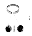
- FIG. 3 depicts conventional wristwatches and bracelets.
- FIG. 4 depicts a first embodiment of an electronic bracelet (bracelet) that can communicate with a smartphone.
- FIG. 5 depicts conventional wristwatches that include centrally located electronics.
- FIG. 6 depicts a second embodiment of a bracelet that includes electronics displaced throughout the bracelet.
- FIG. 7 depicts a third embodiment of a bracelet configured to display different graphics patterns downloaded via a smartphone.
- FIG. 8 depicts a fourth embodiment of a bracelet that includes a near-field communication (NFC) antenna.
- NFC near-field communication
- FIG. 9 depicts a fifth embodiment of a bracelet that includes a light sensor.
- FIG. 10 depicts a sixth embodiment of a bracelet that includes sensors used to sense gestures made by a user wearing the bracelet.
- FIG. 11 depicts a seventh embodiment of a bracelet that includes a locking element.
- FIG. 12 depicts a connector used to supply power and to charge a battery of a device.
- FIG. 13 depicts an eighth embodiment of a bracelet that uses an NFC antenna to wirelessly receive power by induction to charge a battery of the bracelet.
- FIG. 14 depicts a ninth embodiment of a bracelet that includes accelerometers and an electronic compass.
- FIG. 15 depicts a bracelet used in conjunction with a smartphone to define positions of a projection screen when using the bracelet as a pointing device.
- FIG. 16 depicts a variety of conventional wristwatches and bracelets having displays only on top surfaces.
- FIG. 17 depicts a tenth embodiment of a bracelet having a display that wraps around the outside surface of the bracelet, including the sides (i.e., edges) of the bracelet.
- FIG. 18 depicts an eleventh embodiment of a bracelet having several batteries distributed throughout the bracelet.
- FIG. 19 depicts a variety of conventional wristwatches and bracelets that display time in a fixed manner at a central location on the wristwatches and bracelets.
- FIG. 20 depicts various embodiments of a bracelet.
- FIG. 21 depicts a thirteenth embodiment of a bracelet that changes a graphics pattern being displayed according to the changes in environment of the bracelet.
- FIGS. 22 and 23 depict a fourteenth embodiment of a bracelet that changes a graphics pattern being displayed in response to changes in a body parameter of a user.
- FIG. 24 depicts objects that change color in response to different stimuli.
- FIG. 25 depicts conventional wristwatches that display values of different body parameters of a user.
- FIG. 26 depicts conventional computing devices capable of displaying 3D graphics on a screen.
- FIG. 27 depicts a fifteenth embodiment of a bracelet that includes one or more 3D displays.
- FIG. 28 depicts conventional wristwatches having keyboards.
- FIGS. 29 and 30 depict a sixteenth embodiment of a bracelet that includes displays and touch sensors located throughout the bracelet.
- FIGS. 31-33 depict a seventeenth embodiment of a bracelet that includes several modules that can be used to build bracelets having different functions and different sizes.
- FIG. 34A is a schematic of a bracelet in communication with a smartphone.
- FIG. 34B depicts various circuits of the bracelet in accordance with one implementation.
- FIG. 35A is a functional block diagram of a bracelet.
- FIG. 35B depicts a bracelet having a near-field communication antenna.
- FIG. 35C is a functional block diagram of a smartphone.
- FIG. 36A is a detailed functional block diagram of a bracelet.
- FIG. 36B is a functional block diagram of a circuit of a bracelet in accordance with one implementation.
- FIG. 37A depicts a bracelet displaying a graphic pattern.
- FIG. 37B depicts a bracelet having a sensor and displaying a graphic pattern.
- FIGS. 37C and 37D depict a bracelet displaying 3-dimensional graphic patterns.
- FIG. 37E depicts a bracelet having a plurality of sensors.
- FIGS. 38A-38D depict examples of layouts of a circuit of a bracelet.
- FIGS. 39A and 39B are functional block diagrams of examples of interconnecting modules associated with one implementation of a bracelet.
- FIG. 40 depicts a locking module of a bracelet.
- FIG. 40B is a functional block diagram of the locking module of FIG. 40 .
- FIG. 40C is a functional block diagram of a first module of a bracelet that connects to a locking module.
- FIG. 40D is a functional block diagram of a last module of a bracelet that connects to a locking module.
- FIG. 41A is an example of a functional block diagram of a wireless communication circuit of a bracelet.
- FIG. 41B is an example of a functional block diagram of a wireless communication circuit of a bracelet.
- FIG. 41C is an example of a functional block diagram of a near-field communication circuit of a bracelet.
- FIG. 41D is an example of a functional block diagram of a power supply circuit of a bracelet.
- FIG. 41E is an example of a functional block diagram of a vibration and sound circuit of a bracelet.
- FIGS. 42A-42E are flowcharts of methods operable to be performed by a bracelet.
- the present disclosure relates to a an electronic bracelet that can be used as a companion device of another electronic device such as a smartphone, a PC, a laptop, a tablet, a gaming station, or any other electronic device having a processor.
- the amount of electronics and circuits embedded in the bracelet can be kept to a minimum because most of the computing power resides in the other electronic device.
- the electronics and circuits embedded in the bracelet are distributed all around the bracelet, which allows for providing smart, trendy, and appealing design and shape to the bracelet.
- FIG. 1 illustrates a first device 1 in wireless communication with a second device 2 .
- the first device 1 is a companion device to the second device 2 .
- the first device 1 is operable to i) perform one or more functions on the second device 2 , and/or ii) perform one or more functions on behalf of the second device 2 , as described in greater detail below.
- a user operating the second device 2 can perform one or more functions on the first device 1 to alter operation or functions of the first device 1 , as described in greater detail below.
- the first device 1 can be an electronic bracelet or any other device, e.g., a stylus, a ring, a leash, a sticker, a lapel pin, or other item.
- the second device 2 can be a smartphone, a PC, a laptop, a tablet, a gaming station, or any other electronic device having a processor.
- the first device 1 leverages the computing power of the second device 2 .
- the amount of electronics and circuits embedded in the first device 1 can be kept to a minimum since most of the computing power resides in the second device 2 .
- the first device 1 can wirelessly communicate with the second device 2 .
- FIG. 2 illustrates examples of the first device 1 and the second device 2 according to one embodiment.
- the first device 1 can be a bracelet 3
- the second device 2 can be a smartphone 4 .
- the bracelet 3 can communicate with the smartphone 4 via Bluetooth® (BT), for example.
- BT Bluetooth®
- the bracelet 3 can utilize the processing power of the smartphone 4 . Accordingly, the amount of electronics and circuits embedded in the bracelet 3 can be kept to a minimum, and the bracelet 3 can be designed to have smart, trendy, and appealing design and shape.
- the bracelet 3 can be used (as a companion device to the smartphone 4 ) to perform one or more functions on behalf of the smartphone 4 .
- the bracelet 3 can be used to assist the smartphone 4 in completing a transaction—e.g., a near-field communication (NEC) payment transaction or other NFC transaction.
- a user wearing the bracelet 3 may use the bracelet 3 to i) move a cursor or a selection arrow located on a display of the smartphone 4 , or ii) make a selection on the display of the smartphone 4 based on movements or gestures or touching of the bracelet 3 .
- a user wearing the bracelet 3 may use the bracelet 3 to i) move a cursor or a selection arrow located on a display of the smartphone 4 , or ii) make a selection on the display of the smartphone 4 based on movements or gestures or touching of the bracelet 3 .
- FIGS. 3 and 4 illustrate examples of devices that are typically worn on the wrist along with an example of a companion device (e.g., a bracelet 12 ) of a smartphone to be worn on the wrist of a user according to one embodiment.
- a companion device e.g., a bracelet 12
- FIG. 3 examples of devices that are typically worn on a wrist are shown.
- these devices 5 - 10 have various shapes and sizes and are bulky.
- each of these devices 5 - 10 operates as standalone devices. That is, each of these devices 5 - 10 must include processors that provide the computing power for performing the functions of these devices. Accordingly, these devices 5 - 10 are bulky and cannot be designed to have smart, trendy, and appealing design and shape.
- the present disclosure proposes to redefine a wristwatch/high-tech bracelet as an extension or as a companion device of a smartphone, for example.
- the redefined companion device according to the present disclosure includes in the wristwatch/high-tech bracelet only the electronics and circuits which make possible using the device as a companion device.
- FIG. 4 illustrates a smartphone 11 and a bracelet 12 according to one embodiment of the present disclosure.
- the smartphone 11 provides the main computing power for the bracelet 12 .
- the smartphone 11 includes an application processor, a communication processor, a memory processor, and communication circuits such as WiFi, FM, GPS, and Bluetooth. Additionally, the smartphone includes a SIM card and a large-capacity battery.
- the bracelet 12 includes only an interfacing processor, a near-field communication (NFC) circuit, and a Bluetooth communication circuit, for example.
- the Bluetooth communication circuit of the bracelet 12 communicates with the smartphone 11 and/or a PC.
- the Bluetooth communication circuit of the bracelet 12 can communicate with the PC directly or via the smartphone 11 .
- the bracelet 12 includes a smaller battery relative to the smartphone 11 due to the bracelet 12 having fewer circuits than the smartphone 11 .
- the bracelet 12 leverages the computing power of the smartphone 11 .
- Using smaller and fewer components in the bracelet 12 allows for a trendier and smarter design and shape for the bracelet 12 . Additionally, leveraging the processing power and storage capacity of the smartphone 11 avoids duplicating resources such as processors and storage devices on the bracelet 12 .
- FIGS. 5 and 6 details of the proposed design for the companion device according to one embodiment of the present disclosure are shown.
- FIG. 5 examples of other high-tech wristwatches 13 and 14 are shown.
- the other high-tech wristwatches 13 and 14 have all of the electronics contained in a single central part.
- the other high-tech wristwatches 13 and 14 therefore appear bulky and ugly.
- the present disclosure proposes embedding high-tech content or functions into the wristwatch while making the wristwatch appear not bulky and ugly, but trendy and fashionable.
- the present disclosure proposes embedding electronics not in the central part but in the whole bracelet.
- the present disclosure redefines the aesthetic of the wristwatch/bracelet by spreading or distributing the electronics throughout the bracelet. Parts of the bracelet such as electronics and battery are distributed all along the circumference of the bracelet. The parts of the bracelet are not located at one central place like a dial of a wristwatch.
- the present disclosure proposes spreading or distributing LED/OLED displays (rigid or flexible) all around the bracelet.
- a wristwatch 15 with a usual central display and having a central location for embedded electronics is shown.
- a bracelet 16 according to one embodiment of the present disclosure is shown.
- the electronics in the bracelet 16 is spread or distributed throughout the bracelet 16 and is not concentrated just in a central part of the bracelet 16 .
- the display in the bracelet 16 is spread all around the bracelet 16 and is not concentrated just in a central part of the bracelet 16 .
- the bracelet 16 includes functional blocks such as an antenna, an NFC circuit, a battery, a Bluetooth communication circuit, a processor, and so on, which are spread throughout the bracelet 16 as shown.
- Each or some of the functional blocks may include a PCB, an OLED display, and/or a sensor on top of the functional block.
- the proposed designs described in the present disclosure allows for different and more aesthetic, fashionable, and trendy design for a bracelet. Additionally, the proposed designs described in the present disclosure provide a new way of displaying time on a bracelet. For example, hours, minutes, and seconds may be displayed on one or more displays located all around the bracelet 16 , not just on a display centrally located as in the wristwatch 15 . Further, the proposed designs described in the present disclosure provide a new way of using the wristwatch. For example, the displays all around the bracelet 16 can display different graphic patterns according to the environment sensed by sensors located on one or more functional blocks of the bracelet 16 .
- the present disclosure proposes that dedicated applications can be downloaded from a smartphone or a computer to the high-tech companion bracelet/wristwatch.
- downloadable applications, pictures, patterns, etc. are designed for use with computers and smartphones, not for a wristwatch or a high-tech bracelet.
- the dedicated applications proposed by the present disclosure allow downloading applications on the bracelet for customizing the bracelet.
- the dedicated applications can be downloaded to the bracelet to display time in different personalized styles as shown.
- the downloaded applications can be used to display personalized graphics and pictures on the bracelet as shown.
- the downloaded applications take advantage of the technology such as displays, sensors, antennas, communication circuits, accelerometers embedded in the bracelet to create new functionalities, new graphics, and so on, as explained below in detail. Therefore, the bracelet can operate as an open platform since the functionality of the bracelet can be customized by downloading different applications.
- the bracelet of the present disclosure is therefore different than conventional devices such as wristwatches which have a predefined functionality such as displaying time in a fixed manner. Further, the proposed design of the bracelet according to the present disclosure enables a business for developing and selling downloadable applications for high-tech bracelets.
- Applications can be downloaded to the high-tech bracelet through the Bluetooth or WiFi link from a smartphone, a computer, or any other host. Some applications can be parameterized (i.e., customized, adjusted, or personalized) from the smartphone. Some applications can be spread between the smartphone and the bracelet. The applications can evolve depending on sensors and/or options embedded in the bracelet. The bracelet can be used in conjunction with an application to control a remote device.
- the proposed design of the bracelet provides a localized NFC antenna for easily performing various operations and transaction using the bracelet.
- the NFC antenna needs to be presented close to a NFC reader (or other NFC device).
- the NFC antenna on the smartphone may not be easy to use.
- the NFC antenna on the smartphone may have to be pointed and directed to the NFC reader.
- the present disclosure provides a design and shape for the bracelet that helps localize the NFC antenna within the high-tech bracelet.
- the bracelet simply needs to be presented to the NFC reader. Due to the design and shape of the bracelet, the location of the NFC antenna in the bracelet is easy to recognize.
- the location of the NEC antenna in the bracelet can be such that the NFC antenna can be forced to stay at a predetermined location on the wrist so that the location of the NFC antenna can be easily identified.
- the fact that the NFC antenna distinguishes itself inside the bracelet allows for a better utilization of the NFC antenna.
- the NFC antenna may be given a distinctive shape (e.g., an oval shape as shown), and the NFC antenna may be located at an extremity of the bracelet for easy location and use.
- a plurality of NFC antennas may be located at locations around the bracelet so that transactions can be easily performed without the need to locate and direct (i.e., point) the NFC antenna to the reader.
- NFC communication circuitry of the bracelet can receive data corresponding to the transaction from the NFC reader.
- Wireless communication circuitry e.g., Bluetooth circuitry or WiFi circuitry
- the bracelet can then wirelessly transmit the data corresponding to the transaction to another device (e.g., a smartphone) in communication with the bracelet.
- a bracelet can be turned on or off depending on different criteria to save power.
- a light sensor may be embedded in the bracelet to sense the intensity of ambient light. Sensing the intensity of ambient light allows the bracelet to determine when at least the display portion of the bracelet may be turned off. For example, when the bracelet is covered by a sleeve, the bracelet may be placed in a standby mode to save power, where the display portion of the bracelet may be turned off. Conversely, when the bracelet is not covered by a sleeve, the display portion of the bracelet may be turned on. Further, the display portion of the bracelet may be turned off at night regardless of whether a sleeve covers the bracelet, while the display portion of the bracelet may be fashionably turned on at parties at night.
- the function of turning the display portion of the bracelet on and off can be activated or deactivated from the smartphone through a Bluetooth link, for example.
- An application on the smartphone may be parameterized to determine which functions of the bracelet get turned off. For example, to save power, while the display portions of the bracelet may be turned off, the NFC function may be turned on so that transactions that require use of the NFC function may be seamlessly performed even if the sleeve covers the bracelet.
- a bracelet allows using fingers, wrist, or hand gestures to validate or activate functions in the high-tech bracelet or in any other device associated with the bracelet.
- a microphone embedded in the bracelet may detect specific sounds (e.g., a snap of fingers, a clap sound, or a voice command).
- accelerometers orthogonally embedded in the bracelet may detect gestures made using fingers, wrist, and/or hand.
- the electronics in the bracelet detects, decodes, and converts specific sounds or accelerometer signals into activation or validation commands.
- capacitive sensors on the bracelet can be touched using a finger to validate or activate functions in the high-tech bracelet or in any other device associated with the bracelet.
- the bracelet does not need to be continually grasped by a user in order to control a direction or movement of the bracelet. Accordingly, the fingers of a user are free to perform other tasks while the user is using the bracelet to perform functions on or on behalf of another device associated with the bracelet.
- a sound of a snap of fingers can cause the bracelet to turn off the display portion of the bracelet, skip a track of music in a music player associated with the bracelet, or turn off lights in a room.
- a circular motion of the palm around the wrist once or twice in one direction can cause the bracelet to move a power-point presentation on a PC forward by one or two slides and motion in another direction can cause the bracelet to move the power-point presentation on the PC back by one or two slides.
- Still other examples include pressing the capacitive sensor on the bracelet using a finger to activate/deactivate a function of the bracelet or of a device associated with the bracelet.
- the bracelet can be used as a remote control to remotely control other devices associated with the bracelet.
- Many other usages are contemplated. Advantages include ease of use and obviating a need to hold anything in hand to perform such functions.
- a bracelet according to one embodiment of the present disclosure can be split in two parts to allow easy closing of the bracelet around the wrist.
- the high-tech bracelet can be split (in one embodiment) in two parts so that the bracelet can be worn easily on the wrist.
- the two parts are interconnected by a locking element.
- the locking element includes two female connectors that mate with two male connectors of the bracelet.
- At least one of the two connectors of the bracelet includes a flex cable mounted on a magnet as shown.
- the flex cable includes conductors that carry data and power from one connector of the bracelet to another connector of the bracelet via the locking element.
- one of the two connectors of the bracelet may have no cable connections and therefore may have a stronger magnet than the other connector of the bracelet to tightly lock with the locking element.
- the bracelet is shown to have male connectors and the locking element is shown to have female connectors, any combination of male and female connectors may be used for the bracelet and the locking element.
- the connectors of the bracelet are shown to include a magnet, the connectors of the locking element may include a magnet instead of or in addition to the connectors of the bracelet.
- FIGS. 12 and 13 illustrate a technique of supplying power to a bracelet according to one embodiment of the present disclosure.
- a connector typically used to supply power to most hand-held devices is shown.
- Such connectors have various drawbacks that prevent designers from designing improved, smartly shaped/designed bracelets and wristwatches.
- the connectors can be bulky and may not be waterproof. Additionally, such connectors are prone to collecting dust and other materials that can damage the connectors and/or reduce the quality of connections provided by the connectors.
- a bracelet does not require any cables and connectors to charge the batteries in the bracelet. Instead, the bracelet uses the NFC antenna embedded in the bracelet to charge the batteries in the bracelet. Specifically, the NFC antenna embedded in the bracelet communicates with an induction charger, receives power from the induction charger wirelessly, and charges the batteries in the bracelet using the power received wirelessly from the induction charger. Using the NFC antenna as an interface to capture energy by induction eliminates the need for additional hardware such as a cable and connector to charge the batteries in the bracelet.
- the bracelet uses Bluetooth or WiFi link to communicate with other devices such as a smartphone, a PC, a laptop computer, and so on. Accordingly, no wired connections, cables, and connectors are used in such communications as well. Therefore, the bracelet functions entirely without any cables and connectors, which allows designers to design the bracelet in a trendy, fashionable manner. Further, since the bracelet does not use a connector for charging the bracelet, the bracelet is not prone to damage due to dust and/or humidity.
- a powering element can be plugged into one of the two connectors of the bracelet.
- a cable having a micro-USB connector can extend from the powering element and can connect the bracelet to a conventional powering device for charging the batteries of the bracelet.
- a bracelet according to one embodiment of the present disclosure can be used to detect spatial orientation or motion of the arm in order to perform one or more actions.
- the bracelet according to the present disclosure can include embedded orthogonal accelerometers and can optionally include an embedded electronic compass.
- the accelerometers can detect the spatial orientation of the arm wearing the bracelet, and the electronic compass can sense the direction of motion of the arm wearing the bracelet.
- a pair of orthogonal accelerometers can provide a 3D indication of where the arm is pointing.
- the electronic compass can provide the direction in which the arm is pointing.
- the information provided by the accelerometers and the electronic compass can be used to define the orientation and/or the motion of the arm of a user wearing the bracelet.
- the bracelet can be used as a pointing device, a laser pointer, and/or a remote control.
- a user can perform specific predefined motions using the wrist or fingers of the arm wearing the bracelet.
- a microphone embedded in the bracelet can capture the sound of clicking finger to perform an action.
- the user when making a presentation on a projection screen using power-point slides displayed on a PC, the user can initially validate using a smartphone a definition of an upper left corner and a bottom right corner of the projection screen as part of a calibration procedure. Subsequently, the user can twist the wrist wearing the bracelet to move the presentation forward to the next slide or backward to the previous slide. The user can move the pointer on the projection screen by moving the hand on the slide. The electronic compass can detect whether the hand is aiming at the projection screen or elsewhere.
- FIGS. 16 and 17 the design of a bracelet according to one embodiment of the present disclosure allows displaying information all around the bracelet, including on the sides or edges of the bracelet.
- FIG. 16 various wristwatches and bracelets are shown. None of the wristwatches and bracelets are capable of displaying information on the edges or sides of the wristwatches and bracelets.
- the design of the bracelet according to one embodiment of the present disclosure allows using all parts of the bracelet, including the sides or edges of the bracelet, to display information. More specifically, the design of the bracelet according to the present disclosure provides a choice to display graphics on the surface, on the sides (i.e., along the edges), or on both parts of the bracelet.
- the design of the bracelet according to one embodiment of the present disclosure provides many advantages. For example, the design of the bracelet according to one embodiment of the present disclosure provides more freedom to create visual effects such as display one graphic pattern to indicate mood, display another graphic pattern to match clothes, and so on.
- the design of a bracelet allows spreading (i.e., distributing) several batteries throughout the bracelet instead of having a single, large battery, which can make the design of the bracelet bulky.
- Distributing several batteries through out the bracelet provides many advantages. For example, several batteries can power several circuits. Therefore, several circuits providing several functions can be integrated into the bracelet. Further, the several batteries can be small in size. Therefore, the bracelet can have a trendy and compact design while providing many functions using many circuits. Additionally, the small batteries can be of regular shape and size, and custom-shaped (e.g., contoured) batteries are unnecessary.
- the design of a bracelet according to one embodiment of the present disclosure allows displaying time all around the bracelet.
- most wristwatches and bracelets display time only at a central location.
- the bracelet according to the present disclosure can display time all around the bracelet.
- the entire surface of the bracelet, including sides (i.e., edges) of the bracelet can be used to display time. Accordingly, time can be displayed on the bracelet in many ways as shown. Further, unlike in most wristwatches and bracelets, the manner in which the time is displayed on the bracelet can be changed. Therefore, the bracelet according to the present disclosure can be trendy and fashionable.
- a bracelet according to one embodiment of the present disclosure can use sounds or noise from the surrounding environment to influence graphics displayed on the bracelet.
- a bracelet according to one embodiment of the present disclosure includes a microphone that is embedded in the bracelet as shown. The microphone senses sounds in the surrounding environment. Based on the sounds sensed by the microphone, the bracelet creates different graphic patterns and displays the different graphic patterns on the bracelet.
- the graphics displayed on the bracelet can change according to the intensity of the sounds, noises, voices, and so on. For example, the color, pattern, and/or the rhythm of the graphic pattern can be changed according to the intensity of the sounds, noises, voices, and so on, as shown. Graphics can also be changed as a function of recognized (known or predetermined) voices or sounds.
- the present disclosure is not limited sound as an input based on which the graphic pattern displayed on the bracelet can change.
- Other inputs can be used alone or in combination with sound input to change the graphic pattern displayed on the bracelet.
- the other inputs may include, but are not limited to, ambient light sensed by a light sensor, ambient temperature sensed by a temperature sensor, and so on, embedded in the bracelet.
- the bracelet may vibrate in response to one or more of these inputs instead of, or in addition to, changing the graphic patterns displayed on the bracelet.
- the bracelet may include a speaker embedded in the bracelet that can be used to output sounds in response to one or more of these inputs instead of, or in addition to, changing the graphic patterns displayed on the bracelet.
- a bracelet may include various sensors embedded in the bracelet to sense various body parameters of the person wearing the bracelet.
- the sensors embedded in the bracelet may include a blood-pressure sensor, a body temperature sensor, a heart-rate (pulse) sensor, and so on.
- the bracelet can update graphic patterns displayed on the bracelet according to changes in the body parameters in real time.
- the bracelet does not display actual values of the body parameters. Instead, the bracelet indicates changes in values of the body parameters by changing characteristics of the graphic patterns displayed on the bracelet. For example, the color of the graphics pattern displayed around the entire bracelet may change according to the body temperature. As another example, the rhythm of the graphics pattern or animation displayed on the bracelet can change according to the heart rate, and so on.
- FIG. 24 shows objects that may change color according to the temperature of water, may change color according to the temperature of the object itself, or may change color in response to touching the object.
- the bracelet electronically displays graphics patterns on displays all around the bracelet and changes the electronic properties such as color, rhythm, and so on, of the displayed graphics pattern in response to changes in one or more body parameters of the wearer of the bracelet.
- None of the devices shown in FIG. 25 has the capabilities of the bracelet either. For example, these devices display actual values of the body parameters of the person wearing the devices. Further, none of the devices shown in FIG. 25 can change a characteristic of a graphics pattern displayed all around the device in response to a change in a body parameter of the wearer of the device.
- FIGS. 26 and 27 a bracelet having an embedded 3D projection technology to display 3D graphics according to one embodiment of the present disclosure is shown.
- generating 3D graphics generally requires complex computing equipment.
- FIG. 27 shows the bracelet designed according to the present disclosure, which includes 3D displays spread all around the bracelet.
- a flexible 3D display may be wrapped all around the bracelet.
- the user can display 3D pictures all around the bracelet.
- the user can customize the bracelet with 3D graphics.
- the user can download different 3D graphics to the bracelet.
- the design of a bracelet provides displays and sensors embedded in the bracelet to enter pass-codes, passwords, or data to unlock, configure, or validate status in the bracelet.
- most devices use either large, bulky keyboards for such functions, or, to reduce the size of the keyboard, force the size of the keys so small that the keys are difficult to use.
- the sequence of keys used can be observed by a third party, which can compromise security.
- the bracelet designed according to one embodiment of the present disclosure can perform these functions without using a large, bulky keyboard, and without forcing the keys to be too small to use. Since the bracelet is used as a companion device of another device such as the smartphone, most of the data may be entered more conveniently using the smartphone. Some data, however, such as a password to lock/unlock the bracelet needs to be entered from the bracelet. For example, since many security transactions can be performed using the bracelet (e.g., using the NFC function embedded in the bracelet), to secure against a lost or stolen bracelet, the user may configure the bracelet so that the user needs to enter a password to lock/unlock the bracelet.
- the bracelet provides displays and sensors that can be used to enter such data easily and securely.
- the bracelet may include LED/OLED displays and sensors to enter random security codes/passwords.
- the user may use any combination of colors, letters, and/or numbers to create and enter passwords.
- the displays on the bracelet can randomly display the colors, letters, and/or numbers of the passwords all around the bracelet.
- the display is adjusted or reconfigured to match with sensors randomly in order to be activated in a given sequence to enter the code. Accordingly, a third party observing the entry of a code cannot lock/unlock the bracelet by merely mimicking the positions where the user entered the code before.
- not using small keys enables easy data input, and random display of colors, letters, and numbers provides increased security.
- FIGS. 31-33 a modular high-tech bracelet according to one embodiment of the present disclosure is shown.
- Most devices such as wristwatches and bracelets cannot be customized by adding functions as needed.
- the only custom features provided by these devices include choice of color and material used to manufacture these devices. Further, while different designs are available, the designs are fixed and cannot be changed or upgraded as needed.
- the modular design of the bracelet according to the present disclosure allows users to customize and personalize the bracelet in terms of cost and functions.
- an electronic bracelet/wristwatch may be manufactured by assembling various modules.
- the user can assemble the bracelet by plugging together a selection of modules according to the cost and functions desired by the user.
- each module may have a connector to connect to another module.
- a mechanical connector is shown for example only. Instead, a magnetic connector may be used as described before.
- each module can include a functionality either partially or wholly.
- a power supply module can include a battery, an OLED display, and sensor.
- the NFC function can be spread over two modules: one module may include the NFC antenna while another module may include the circuit that performs the NFC functions using the NFC antenna. Any combination of functions may be incorporated in each module.
- Modules can be added or removed at any time to reconfigure the bracelet.
- the modularity of the bracelet allows the user to change the size of the bracelet to fit the wrist.
- the cost of the bracelet can also be adjusted (customized) since each module can have a different price depending on the functionality implemented by the module.
- the modularity of the bracelet provides the bracelet a personal touch.
- Each module has an identity and a function associated with the module. The user can select and buy only the desired functions. Further, the user can remove a module not used daily and add the module when desired. The user can also change the combination of modules to have the desired functionality and still have the bracelet fit around the wrist.
- an interconnecting module connects two modules of the bracelet.
- the interconnecting module may or may not provide other functions.
- the interconnecting module may only include OLEDs and a touch sensor.
- circuits that can be used in the bracelet are provided.
- the circuits described below provide only examples of implementations of the bracelet.
- the circuits described below can implement one or more of the embodiments described above in a single bracelet.
- the circuits, while occasionally shown in modular form, need not be modular. Instead, the bracelet may be a single contiguous unit, and the circuits may be spread within the bracelet. Modularity, where shown, is shown only to aid understanding how the circuits can operate and provide the functionality even when some other circuits may be added or removed in the modular embodiment.
- the present disclosure relates to an electronic bracelet (bracelet) that can be used as a companion device of a smartphone.
- the bracelet can include a wireless communication circuit such as a BluetoothTM (BT) circuit operable to communicate with the smartphone.
- BT BluetoothTM
- the bracelet can include additional circuits that provide additional functions by utilizing the processing and storage capabilities of the smartphone.
- the bracelet can include a near-field communication (NEC) circuit that authenticates transactions and exchanges identifying information of the person wearing the bracelet via a NEC antenna in the bracelet.
- the bracelet can also include devices such as an accelerometer, a gyroscope, an electronic compass, and a global positioning system (GPS) circuit to detect gestures.
- the gestures can be used to control functions of the bracelet and functions of a device associated with the bracelet.
- the bracelet can include one or more batteries that are distributed around the bracelet. The batteries can be charged via the NFC antenna instead of using cables and connectors.
- the bracelet can include display devices such as organic light-emitting diodes (OLEDs), LEDs, liquid crystal displays (LCDs), and/or plasma displays that are distributed around the bracelet to display time, graphics, and other data.
- OLEDs organic light-emitting diodes
- LCDs liquid crystal displays
- plasma displays plasma displays that are distributed around the bracelet to display time, graphics, and other data.
- OLEDs are used for example only. Different display devices, alone or in combination, may be used instead.
- the bracelet can include sensors that sense biometric data such as temperature, pulse, and blood-pressure, which can be used to display different patterns on the OLEDs.
- the bracelet can include additional sensors such as microphones and light sensors that sense environmental data related to the environment around the bracelet, which can be used to display different patterns on the OLEDs.
- the user can download applications via the smartphone or other devices such as laptop computers.
- the applications can be customized according to the configuration of the bracelet to utilize various features of the bracelet.
- the applications can be executed partly or wholly by the smartphone and/or the bracelet by leveraging the processing and storage capabilities of the smartphone.
- the bracelet can be modular.
- the user can add/remove modules to add/remove functionality as desired.
- Interconnecting modules can be inserted between the modules to increase or decrease the size of the bracelet.
- a single module can include one or more functions such as an OLED-based display, a battery, and a capacitive sensor. Modularity allows the user to adjust the size of the bracelet according to wrist size.
- a bracelet 100 according to the present disclosure is shown.
- the bracelet 100 communicates with a smartphone 102 wirelessly using a short-range wireless communication protocol such as Bluetooth® (BT) or WiFi.
- BT Bluetooth®
- WiFi Wireless Fidelity
- the bracelet 100 can include a plurality of circuits.
- the bracelet 100 can include a BT circuit 104 , a near-field communication (NFC) circuit 106 , an NFC antenna 108 , a first power supply circuit (including a first batte) 110 , a first sensor circuit (e.g., a light sensor circuit) 112 , a second power supply circuit (including a second battery) 114 , a second sensor circuit (e.g., a sound sensor circuit) 116 , a third power supply circuit (including a third battery) 118 , a third sensor circuit (e.g., a gesture sensor circuit) 120 , and a wireless communication circuit (e.g., a WiFi circuit) 122 .
- the operation of these circuits is explained below.
- One or more of these circuits may be omitted and/or one or more additional circuits may be added according to the needs of the user.
- one or more of these circuits can be integrated into one or more modules as explained below.
- one or more interconnecting modules (explained below) may be inserted into the bracelet 100 . Further, these modules may be arranged in a different order than the order shown.
- the bracelet 100 can include the BT circuit 104 , the NFC circuit 106 , the NFC antenna 108 , and the first power supply circuit (including the first battery) 110 .
- the BT circuit 104 communicates with the smartphone 102 .
- the NEC circuit 106 can communicate with an external device (e.g., an automatic teller machine or another bracelet) via the NFC antenna 108 .
- the NFC circuit 106 can exchange authentication and identification information of the user of the bracelet 100 with the external device via the NFC antenna 108 to authenticate transactions (e.g., banking transactions) performed by the user.
- the authentication and identification information may include information stored in a subscriber identity module of the smartphone 102 (see element 157 in FIG. 35C ).
- the user wearing the bracelet 100 can exchange personal contact information (e.g., email and phone information) via the NFC antenna 108 while shaking hands with another user also wearing a bracelet.
- the NFC antenna 108 may be located and/or shaped distinctively in the bracelet 100 .
- the NFC antenna 108 may have a distinctive shape as shown. An oval shape is shown for example only. Any other shape may be used instead. In some implementations, a distinctive shape may not be used. Instead, for effective communication, the NFC antenna 108 may be located, for example, at an end-point or center of the bracelet 100 .
- the first power supply circuit 130 supplies power to the BT circuit 104 and the NEC circuit 106 .
- Additional power supply circuits e.g., the second power supply circuit 114 and the third power supply circuit 118 shown in FIG. 34B ) may be included in the bracelet 100 to supply power to other circuits of the bracelet 100 .
- Using multiple power supply circuits (and multiple batteries) allows using several small batteries instead of using a single large, bulky battery.
- the NFC antenna 108 may also be used to receive power from a power source through inductive coupling.
- the power received from the power source via the NFC antenna 108 may be used to charge the batteries of the bracelet 100 . Accordingly, the batteries of the bracelet 100 can be charged without using any cables and connectors.
- the batteries of the bracelet 100 can be charged using a powering module that connects to one of the circuits of the bracelet 100 and that includes a suitable cable (e.g., a USB cable) that plugs into a power source.
- the smartphone 102 includes one or more processors (e.g., application and communication processors) 150 , one or more storage devices (e.g., solid-state disks) 152 , one or more communication modules (e.g., a cellular module, a BT module, a WiFi module, and a GPS module) 154 , and a power supply module (including a battery) 156 .
- the application and communication processors 150 respectively process application-related and communication-related data.
- the storage devices 152 store data.
- the one or more communication modules 154 communicate with different devices using respective communication protocols.
- the BT module communicates with BT-compatible devices including the bracelet 100 .
- the cellular module communicates with one or more cellular towers.
- the WiFi module communicates with a WiFi network.
- the power supply module 156 supplies power to the one or more processors 150 , the one or more storage devices 152 , and the one or more communication modules 154 .
- the bracelet 100 can include a plurality of circuits connected in series as shown.
- the plurality of circuits can include, in general, a first circuit 200 , a second circuit 202 , a third circuit 206 , . . . , and a last circuit 220 .
- the first circuit 200 , the second circuit 202 , the third circuit 206 , . . . , or the last circuit 220 is generally referred to as an N th circuit throughout the disclosure.
- one or more of the plurality of circuits may be implemented in one or more modules. Further, one or more interconnecting modules such as a first interconnecting module 204 - 1 , a second interconnecting module 204 - 2 (not shown, collectively interconnecting modules 204 ), and so on may be used to interconnect the one or more modules of the bracelet 100 .
- interconnecting modules such as a first interconnecting module 204 - 1 , a second interconnecting module 204 - 2 (not shown, collectively interconnecting modules 204 ), and so on may be used to interconnect the one or more modules of the bracelet 100 .
- the bracelet 100 can include additional (or fewer) N th circuits and additional (or no) interconnecting modules 204 depending on the configuration and features selected by the user. Any of the N th circuits can include one or more of the circuits shown in FIG. 34B .
- the last circuit 220 can be connected to the first circuit 200 directly, via the interconnecting module 204 , or via a locking module (described below). In some implementations, the last circuit 220 may not be connected to the first circuit 200 (e.g., see FIG. 35B ).
- the N th circuit can include an interface circuit 252 , a processing circuit 254 , and an interface circuit 256 . Additionally, the N th circuit can include OLEDs 260 and one or more sensors 262 .
- the Nth circuit may also include a male connector 250 and a female connector 258 .
- the male connector 250 of one N th circuit connects to the female connector 258 of another N th circuit.
- the male connector 250 and the female connector 258 may be magnetic (i.e., may include magnets).
- the interface circuits 252 and 256 provide a suitable interface for interfacing the circuits of the bracelet 100 .
- the interface circuits 252 and 256 may provide power and data transmission lines for supplying power and for communicating data from one circuit to another circuit of the bracelet 100 .
- the interface circuits 252 and 256 may include suitable terminations for balancing the transmission lines.
- One of the interface circuits 252 and 256 may assign an identifier (ID) to an N th circuit (or an interconnecting module or a locking module) as each circuit is added to the bracelet 100 .
- ID an identifier
- the first circuit 200 may be assigned an ID 1 ; the second circuit 202 may be assigned an ID 2 , the first interconnecting module 204 - 1 may be assigned an ID 3 ; and so on.
- These identifiers can be retained or changed dynamically when the bracelet 100 is modular and the modules of the bracelet 100 are rearranged by the user.
- the user can select which circuit or module can have an ID of 1 (e.g., using the smartphone 102 or using a capacitive sensor on the module), and then remaining circuits or modules configure themselves when added.
- the IDs may be included in the signals transmitted by each circuit of the bracelet 100 . Further, if one of the circuits transmits a signal to another circuit, the ID of the receiving circuit may be included in the signals. Such a signaling scheme can help, for example, in displaying different graphic patterns on the displays of different circuits, or when a sensor on one circuit senses a condition that requires a device (e.g., a display, a speaker, or a vibrator) on another circuit to react to the condition.
- a device e.g., a display, a speaker, or a vibrator
- the processing circuit 254 performs processing related to the function(s) performed by the N th circuit. For example, if the N th circuit is the BT circuit 104 , the processing circuit 254 performs BT processing; if the N th circuit is the NFC circuit 106 , the processing circuit 254 performs NFC processing; and so on.
- the processing circuit 254 can perform multiple functions if the N th circuit includes more than one of the circuit of the bracelet 100 . For example, if the N th circuit includes the BT circuit 104 and a WiFi circuit, the processing circuit 254 can perform BT processing and WiFi processing.
- the processing circuit 254 includes a display circuit to control the OLEDs 260 .
- the OLEDs 260 can be controlled using an application downloaded via the smartphone 102 or another external device (e.g., a laptop).
- the OLEDs 260 can also be controlled based on a variety of conditions and data sensed by different sensors as explained below.
- the OLEDs 260 may be distributed throughout the bracelet 100 .
- the OLEDs 260 may be distributed on a plurality of modules of the bracelet 100 .
- the OLEDs 260 may be distributed on an outer surface 300 of the bracelet 100 .
- the OLEDs 260 may be distributed on one or both side surfaces 302 of the bracelet 100 .
- the OLEDs 260 may be used to display time in different ways. For example, the hours and minutes may be displayed on the outer surfaces 300 at two different locations (e.g., of two different modules when the bracelet 100 is modular) while the seconds may be displayed by lighting one of the OLEDs 260 per second on one or both of the sides surfaces 302 of the bracelet 100 . Other ways of displaying time are contemplated.
- the OLEDs 260 can be used to display different graphic patterns as shown in FIGS. 37A and 37B .
- the OLEDs 260 can also be used to display three-dimensional (3D) images as shown in FIGS. 37C (e.g., a helix) and 37 D (e.g., a tree).
- the one or more sensors 262 may include one or more environmental sensors and biometric sensors.
- the environmental sensors may include a light sensor, an ambient temperature sensor (both shown generally at 304 ), and a sound sensor (e.g., a microphone, shown generally at 306 ). These environmental sensors may be located on the outer and/or side surfaces 300 , 302 of the bracelet 100 to sense environmental data of the environment around the bracelet 100 .
- the biometric sensors may include a pulse sensor, a body temperature sensor, and/or a blood-pressure sensor (generally shown at 308 )). These biometric sensors may be located on an inner surface 310 of the bracelet 100 (proximate to the skin of the wearer of the bracelet 100 ) to sense biometric data of the user wearing the bracelet 100 .
- the environmental sensors may sense environmental data surrounding the bracelet 100 such as ambient light, ambient temperature, and sound (e.g., music, clapping or snapping of fingers by the wearer of the bracelet 100 ).
- the biometric sensors may sense biometric data of the wearer of the bracelet 100 (e.g., pulse rate, blood-pressure, body temperature, and so on).
- the OLEDs 260 can be turned on or off (or dimmed or brightened) depending on these data.
- the OLEDs 260 can display different graphic patterns based on these data.
- the OLEDs 260 may be turned on or off, or dimmed, or brightened when the ambient light crosses a predetermined threshold.
- the display patterns may flash at a predetermined frequency based on different ambient light/sound/temperature conditions.
- the bracelet 100 can transmit a signal to a device to control (e.g., turn on or off) the device based on a clap or snap of fingers by the wearer of the bracelet 100 .
- the OLEDs 260 may display a pattern resembling an electrocardiogram when the pulse rate or blood-pressure is normal (within a predetermined range) or crosses a predetermined threshold.
- values of sensed biometric parameters are not displayed on the OLEDs 260 .
- a graphic pattern is displayed on the OLEDs 260 based on the sensed biometric parameters.
- the display patterns may flash at a predetermined frequency based on different biometric conditions.
- an alarm may sound via a speaker on the bracelet 100 when a biometric parameter is above or below a predetermined threshold.
- the one or more sensors 262 may include one or more gesture sensors (e.g., accelerometers, a gyroscope, an electronic compass, and/or a GPS circuit, generally shown at 304 , 308 , and 312 ).
- an electronic compass may be located at 312
- the accelerometers may be distributed in one or more of the N th circuits and may be arranged orthogonal to each other (e.g., at 304 and 308 ).
- the gesture sensors may be used to detect gestures made by the wearer of the bracelet 100 .
- the gesture sensors may detect movements of hand, fingers, and arm of the wearer of the bracelet 100 . These movements can be translated into actions.
- information provided by the accelerometers and the electronic compass can be used to define spatial orientation and/or motion of the arm.
- two orthogonal accelerometers can provide a 3D indication of where the arm is pointing, and in addition, the electronic compass can provide the direction in which the arm is pointing. This allows turning the bracelet 100 into a pointing device, a laser pointer, or a remote control.
- One or more circuits of the bracelet 100 can include a device generating a signal suitable for performing the function of a pointing device, a laser pointer, or a remote control.
- one or more circuits of the bracelet 100 can include a laser beam generator circuit to generate a laser beam, an infrared circuit to generate an infrared beam, and so on.
- the user can perform predefined motions using the wrist or fingers, for example.
- the microphone in one of the circuits of the bracelet 100 can capture sound of snapping fingers, for example, to initiate an action.
- the user wearing the bracelet 100 can initially perform a calibration procedure as follows.
- the user can point the hand wearing the bracelet 100 to the upper left and bottom right corners of the projection screen, for example.
- the spatial orientations of the hand pointing to the upper left and bottom right corners of the projection screen are determined.
- the pointed location on the projection screen can be determined.
- a pointer e.g., a laser beam
- the user can also twist the hand wearing the bracelet 100 to move to a next or a previous slide. For example, rotating the hand wearing the bracelet 100 once clockwise may move the presentation forward by one slide, and rotating the hand once anticlockwise may move the presentation backward by one slide. Further, rotating the hand continuously in either direction will continue to move the presentation further in the corresponding direction. Also, the speed of moving the presentation forward or backward can be varied by varying the speed of rotating the hand.
- the printed circuit board may include, for example, the male connector 250 , the interface circuit 252 , the processing circuit 254 , the interface circuit 256 , and the female connector 258 shown in FIG. 36B .
- the N th circuit can include a sensor (e.g., a capacitive sensor or any of the sensors 262 ) and the OLEDs 260 .
- the N th circuit can include a sensor (e.g., a capacitive sensor or any of the sensors 262 ), the OLEDs 260 , and a power supply circuit including a battery.
- the N th circuit can include the OLEDs 36 U and one or more antennas (e.g., a BT antenna, a WiFi antenna, or a single BT/WiFi antenna).
- the N th circuit can include the OLEDs 260 , one or more antennas (e.g., a BT antenna, a WiFi antenna, or a single BT/WiFi antenna), and a power supply circuit including a battery. Many other combinations are contemplated.
- the interconnecting module 204 may include the male connector 250 , the interface circuit 252 , the processing circuit 254 , the interface circuit 256 , the female connector 258 , the OLEDs 260 , and a display circuit 270 to control the OLEDs 260 . Additionally, the interconnecting module 204 may include one or more of the sensors 262 and corresponding processing circuit. In FIG. 39B , the interconnecting module 204 may include only the male connector 250 , the interface circuit 252 , the processing circuit 254 , the interface circuit 256 , and the female connector 258 .
- FIGS. 40A-40D an example of a locking module 400 is shown.
- the locking module 400 locks into two ends of the bracelet 100 as shown.
- the locking module 400 has a first end 402 and a second end 404 .
- the bracelet 100 has a first end 406 and a second end 408 .
- the first end 406 of the bracelet 100 is male type and includes a magnet and a flex cable including conductors for power and data lines.
- the second end 408 of the bracelet 100 is also male type and includes a magnet but no power and data connections.
- the first end 402 of the locking module 400 is female type and includes power and data connections corresponding to the first end 406 of the bracelet 100 .
- the second end 404 of the locking module 400 is also female type and does not include power and data connections. Accordingly, the magnet of the second end 408 of the bracelet 100 can be stronger than the magnet of the first end 406 of the bracelet.
- FIG. 40B a functional block diagram of the locking module 400 is shown.
- the locking module 400 is shown connected to a first module 200 - 1 and a last module 220 - 1 of the bracelet 100 .
- the locking module 400 includes a female connector 450 , the interface circuit 252 , and a female socket 452 .
- the locking module 400 can include the OLEDs 260 and/or a sensor (e.g., a capacitive sensor or any of the sensors 262 ) and corresponding processing circuits. If the locking module 400 includes any of the OLEDs 260 and/or the sensors 262 and corresponding processing circuits, the locking module 400 also includes the interface circuit 256 to provide terminations to the transmission lines carrying power and data.
- the locking module 400 may not be used if the bracelet 100 is modular and is fully configured using many of the functional and interconnecting modules. Accordingly, the functional and interconnecting modules of the bracelet 100 may interconnect using the male and female connectors 250 and 258 shown in FIGS. 36B and 39A . When the locking module 400 is used, however, the first and last modules of the bracelet 100 may have different ends as shown in FIG. 40A and therefore may have different connectors as shown in FIGS. 40C and 40D .
- the first module 200 - 1 of the bracelet 100 may include a male connector 454 that is magnetic and that plugs into the first end 402 of the locking module 400 as shown in FIG. 40A .
- the last module 220 - 1 of the bracelet 100 may also include a male connector 456 that is magnetic and that plugs into the second end 404 of the locking module 400 as shown in FIG. 40A .
- the magnet of the male connector 456 of the last module 220 - 1 of the bracelet 100 may be stronger than the magnet of the male connector 454 of the first module 200 - 1 of the bracelet 100 .
- the wireless communication circuit 122 includes the male connector 250 , the interface circuit 252 , the processing circuit 254 , the interface circuit 256 , and the female connector 258 .
- the wireless communication circuit 122 may additionally include the OLEDs 260 and one or more of the sensors 262 .
- the processing circuit 254 may include a BT circuit 500 , a BT antenna 502 , the display circuit 270 , a signal generator circuit 504 , and a customization circuit 506 .
- the circuits in the processing circuit 254 communicate with a bus 508 that includes the power and data transmission lines.
- the BT circuit 500 communicates with the smartphone 102 or any other BT device via the BT antenna 502 .
- the BT circuit 500 may receive an application from the smartphone 102 or a device (e.g., a laptop).
- the customization circuit 506 customizes the application according to the configuration of the wireless communication circuit 122 . For example, if the application includes features used to display information, but the wireless communication circuit 122 does not include the OLEDs 260 , the customization circuit 506 disables the display features of the application. As another example, if the application includes features used to output sounds, and the wireless communication circuit 122 includes a speaker, the customization circuit 506 enables the sound features of the application.
- the signal generator circuit 504 generates signals based on conditions sensed by the sensors 262 .
- the signals are transmitted to other circuits of the wireless communication circuit 122 via the bus 508 .
- the signal generator circuit 504 generates a signal and outputs the signal to the bus 508 .
- the wireless communication circuit 122 includes the OLEDs 260
- the signal is communicated to the display circuit 270 to control the OLEDs 260 .
- the signal is communicated to other circuits of the bracelet 100 so that the OLEDs 260 of the other circuits of the bracelet 100 can be controlled.
- the OLEDs 260 can also be controlled based on a downloaded application. For example, stock prices received from the smartphone 102 via the BT circuit 500 can be displayed on the OLEDs 260 all around the bracelet 100 based on the application.
- the application may run wholly on the smartphone 102 , wholly on the bracelet 100 , or partly on the smartphone 102 and partly on the bracelet 100 .
- pictures, patterns, time, holograms, and other types of data may be displayed on the OLEDs 260 all around the bracelet 100 based on different applications.
- a combination of the sensors 262 and applications may be used to control the OLEDs 260 .
- a capacitive sensor included in the sensors 262 can be used to configure the wireless communication circuit 122 or other circuits of the bracelet 100 .
- the user can execute an application on the smartphone 102 and use the capacitive sensor on the wireless communication circuit 122 to determine whether the OLEDs 260 on the wireless communication circuit 122 will display a portion of time (e.g., hours or minutes).
- the capacitive sensors and the OLEDs 260 on the circuits of the bracelet 100 can provide a keypad with which to configure an application and/or functions of the bracelet. For example, characters/shapes displayed on the circuits of the bracelet 100 can be selected by touching the capacitive sensors on the circuits to lock/unlock the bracelet 100 as explained below.
- the capacitive sensor may be used to send a signal, for example, via the BT antenna 502 , via one of the OLEDs 260 , or via a speaker in one of the circuits of the bracelet 100 , to a device to control the device (e.g., turn on or turn off the device).
- the signals generated by the signal generator circuit 504 can be transmitted to another circuit of the bracelet 100 comprising a speaker, which can sound an alarm based on a condition sensed by one of the sensors 262 .
- the signals generated by the signal generator circuit 504 can also be used to control other devices by generating signals such as infrared signals using suitable signal generators in one or more circuits of the bracelet 100 .
- FIG. 41B another example of a wireless communication circuit 122 - 1 is shown.
- the wireless communication circuit 122 - 1 includes a BT/WiFi circuit 550 and a BT/WiFi antenna 552 in addition to other circuits shown and already described. Functions of other circuits of the bracelet 100 may be similarly combined in a single circuit.
- FIG. 41C an example of the NFC circuit 106 is shown.
- the NFC circuit 106 includes a NFC processing circuit 580 and the NEC antenna 108 in addition to other circuits shown and already described.
- FIG. 41D an example of a power supply circuit (e.g., the first power supply circuit 110 ) is shown.
- the power supply circuit may include a power management circuit 600 and a battery 602 in addition to other circuits shown and already described.
- the power management circuit 600 controls the charging of the battery battery 602 and supply of power from the battery 602 to the circuits of the bracelet 100 .
- the power management circuit 600 charges the battery 602 based on the power received by the NEC circuit 106 via the NFC antenna 108 from a power source through inductive coupling.
- the power management circuit 600 charges the battery 602 based on power received by one of the circuits of the bracelet 100 connected to an external power source via a powering module and a cable.
- the power management circuit 600 supplies power from the battery 602 to the circuits of the bracelet 100 based on signals received from the signal generator circuit 504 .
- the signal generator circuit 504 may generate signals to turn on, turn off, brighten, or dim the OLEDs 260 wholly or partly in one or more circuits of the bracelet 100 .
- the power management circuit 600 can also shutdown (i.e., turn off power or supply less than normal power to) one or more circuits of the bracelet 100 .
- This feature can be controlled from the smartphone 102 via an application that the user can customize according to the configuration of the bracelet 100 .
- the application then communicates with the power management circuit 600 via a BT link between the smartphone 102 and the bracelet 100 .
- the power management circuit 600 accordingly activates or deactivates one or more circuits of the bracelet 100 wholly or partly.
- the OLEDs 260 may be turned off if the light sensor detects that a shirt sleeve is covering the bracelet 100 .
- the NFC circuit 106 may be still active (i.e., turned on) so that a transaction requiring the authentication information via the NFC circuit 106 can still be performed.
- the OLEDs 260 may be turned off at night, the OLEDs 260 may be turned on at a party in spite of dark surroundings sensed by the light sensor. Further, a graphic pattern in fashion, making a statement, and/or matching the attire and/or mood of the user may be displayed.
- the vibration/sound circuit 650 may include a vibration circuit 652 , a sound circuit 654 , and a speaker 666 in addition to other circuits shown and already described.
- the vibration circuit 652 may include a piezoelectric crystal that can vibrate based on a signal generated by the signal generator circuit 504 .
- the BT circuit 500 of the wireless communication circuit 122 shown in FIG. 41A may sense when the smartphone 102 receives a call or a voice/text message and when the smartphone 102 is set to vibrate mode. Based on the sensing, the signal generator circuit 504 of the wireless communication circuit 122 or the vibration/sound circuit 650 may generate a signal. The signal can cause the vibration circuit 652 to vibrate the bracelet 100 . Alternatively or additionally, the signal can cause the OLEDs 260 on one or more circuits of the bracelet 100 to flash. Alternatively or additionally, the signal may generate sounds through the speaker 666 .
- the sound circuit 654 can generate sounds through the speaker 666 in response to signals received from one or more of the sensors 262 and/or based on a downloaded multimedia application.
- the sound circuit 654 can also generate sounds through the speaker 666 at predetermined times (e.g., as in wakeup alarms or when a biometric condition (e.g., a heart attack) occurs).
- the bracelet 100 includes security features to protect against loss or theft.
- the bracelet 100 can be locked and unlocked using a password.
- the password may include any alphanumeric characters, shapes, colors, or combinations therefore displayed on the OLEDs 260 .
- the user may enter the password by touching the capacitive sensors on the circuits of the bracelet 100 on which the characters of the password are displayed. The positions of the characters of the password on the bracelet 100 can be changed after each use.
- a password having four characters C 1 , C 2 , C 3 , and C 4 may be initially displayed on the OLEDs 260 of the first, second, third, and fourth circuits, respectively, of the bracelet 100 .
- the characters of the password may be displayed in different positions (i.e., different circuits) on the bracelet 100 .
- the characters C 2 , C 4 , C 1 , C 3 may be displayed on the OLEDs 260 on the first, second, third, and fourth circuits of the bracelet 100 , respectively.
- the characters C 1 , C 2 , C 3 , and C 4 may be displayed on the OLEDs 260 on the fifth, second, seventh, and first circuits of the bracelet 100 , respectively.
- FIGS. 42A-42E various methods performed by the bracelet 100 are shown.
- a method 700 performed by the bracelet for exchanging authentication information via a NFC antenna is shown.
- the user executes an application (e.g., a banking application) on the smartphone and/or the bracelet.
- the user extends the hand wearing the bracelet proximate to an NFC-based security system such as an automated teller machine (ATM).
- ATM automated teller machine
- the bracelet exchanges the authentication information of the user via the NFC antenna of the bracelet.
- the security system verifies the authentication information, the user executes a transaction securely with the NFC-based security system.
- a method 750 performed by the bracelet for displaying time on the bracelet is shown.
- the user executes an application on the smartphone and/or the bracelet.
- the user configures the application to display time on the bracelet. For example, time can be displayed in different ways described above.
- the application configures the display circuits of the bracelet to display different portions of the time.
- the different circuits of the bracelet display the time according to the selection made by the user.
- a method 800 performed by the bracelet for displaying different graphic patterns on the bracelet is shown.
- the user executes an application on the smartphone and/or the bracelet.
- the user configures the application to display a graphic pattern on the bracelet.
- a sensor of the bracelet senses environmental or biometric data.
- the circuits of the bracelet alter the graphic pattern according to the environmental or biometric data.
- a method 850 performed by the bracelet for locking/unlocking the bracelet is shown.
- the user executes an application on the smartphone and/or the bracelet and selects a password to lock/unlock the bracelet.
- the user determines whether to lock/unlock the bracelet.
- the application displays characters/shapes on the bracelet in a first sequence.
- the application senses characters/shapes selected by the user by touching capacitive sensors on the bracelet circuits.
- the application determines if the selections made by the user match the password.
- the method 850 ends if the password does not match.
- the bracelet is locked/unlocked if the password matches.
- the user determines whether to lock/unlock the bracelet. For example, the bracelet may be locked if no operation is performed for a predetermined time and may need to be unlocked before performing an operation.
- the application displays characters/shapes on the bracelet in a second sequence as described above.
- the bracelet is locked/unlocked according to results obtained at 858 - 862 .
- FIG. 42E a method 900 performed by the bracelet for sensing gestures made by the hand wearing the bracelet is shown.
- the user makes a power-point presentation using a laptop. Similar methods may be used in other applications.
- the user executes an application on the smartphone and/or the laptop.
- the user uses the hand wearing the bracelet, the user points to two diametrically opposite corners of the projection screen on which the power-point slides are projected.
- the application determines the spatial orientations of the hand when pointing to the two corners.
- the application obtains spatial information from the gesture sensors as the hand points to a location on the projection screen.
- the application uses the spatial orientations as a reference and the obtained spatial information corresponding to the pointed location, the application determines the location on the projection screen where the hand is pointing.
- one of the circuits of the bracelet transmits a pointer such as a laser beam to the pointed location on the projection screen.
- the user can use the bracelet as a pointing device and freely point to any location on the projection screen.
- the user can further rotate the hand in two opposite directions and/or snap fingers to move the presentation forward and backward.
- the user can use the bracelet as a remote control.
- module may refer to, be part of, or include an Application Specific Integrated Circuit (ASIC); an electronic circuit; a combinational logic circuit; a field programmable gate array (FPGA); a processor (shared, dedicated, or group) that executes code; other suitable hardware components that provide the described functionality; or a combination of some or all of the above, such as in a system-on-chip.
- ASIC Application Specific Integrated Circuit
- FPGA field programmable gate array
- the term module may include memory (shared, dedicated, or group) that stores code executed by the processor.
- code may include software, firmware, and/or microcode, and may refer to programs, routines, functions, classes, and/or objects.
- shared means that some or all code from multiple modules may be executed using a single (shared) processor. In addition, some or all code from multiple modules may be stored by a single (shared) memory.
- group means that some or all code from a single module may be executed using a group of processors. In addition, some or all code from a single module may be stored using a group of memories.
- the apparatuses and methods described herein may be implemented by one or more computer programs executed by one or more processors.
- the computer programs include processor-executable instructions that are stored on a non-transitory tangible computer readable medium.
- the computer programs may also include stored data.
- Non-limiting examples of the non-transitory tangible computer readable medium are nonvolatile memory, magnetic storage, and optical storage.
Abstract
Description
Claims (17)
Priority Applications (1)
| Application Number | Priority Date | Filing Date | Title |
|---|---|---|---|
| US13/421,041 US9288836B1 (en) | 2011-03-18 | 2012-03-15 | Electronic bracelet |
Applications Claiming Priority (3)
| Application Number | Priority Date | Filing Date | Title |
|---|---|---|---|
| US201161454232P | 2011-03-18 | 2011-03-18 | |
| US201161454220P | 2011-03-18 | 2011-03-18 | |
| US13/421,041 US9288836B1 (en) | 2011-03-18 | 2012-03-15 | Electronic bracelet |
Publications (1)
| Publication Number | Publication Date |
|---|---|
| US9288836B1 true US9288836B1 (en) | 2016-03-15 |
Family
ID=55450324
Family Applications (1)
| Application Number | Title | Priority Date | Filing Date |
|---|---|---|---|
| US13/421,041 Expired - Fee Related US9288836B1 (en) | 2011-03-18 | 2012-03-15 | Electronic bracelet |
Country Status (1)
| Country | Link |
|---|---|
| US (1) | US9288836B1 (en) |
Cited By (27)
| Publication number | Priority date | Publication date | Assignee | Title |
|---|---|---|---|---|
| US20150067366A1 (en) * | 2013-09-05 | 2015-03-05 | Lenovo (Beijing) Co., Ltd. | Electronic Apparatus And Information Processing Method |
| US20150154936A1 (en) * | 2013-12-02 | 2015-06-04 | Samsung Electronics Co., Ltd. | Mobile device and control method thereof |
| US20150220110A1 (en) * | 2014-01-31 | 2015-08-06 | Usquare Soft Inc. | Devices and methods for portable processing and application execution |
| US20150374079A1 (en) * | 2014-06-27 | 2015-12-31 | David Gareth Zebley | Interactive bracelet for prayer or meditation |
| US20160013825A1 (en) * | 2013-08-27 | 2016-01-14 | Sharp Kabushiki Kaisha | Wireless device attaching band, and wireless device |
| US20160183795A1 (en) * | 2014-12-26 | 2016-06-30 | Intel Corporation | Electronic device system to display biometric feedback |
| US20160234358A9 (en) * | 2012-05-09 | 2016-08-11 | Tara Chand Singhal | Apparatus and method for an alternate form-factor handheld smart phone device |
| US20170038827A1 (en) * | 2015-08-07 | 2017-02-09 | Mediatek Inc. | Wearable electronic device and operating method |
| US20170077974A1 (en) * | 2015-09-11 | 2017-03-16 | Panasonic Intellectual Property Corporation Of America | Wearable terminal mountable on part of body of user |
| US20170093447A1 (en) * | 2015-08-05 | 2017-03-30 | Eski Inc. | Methods and apparatus for communicating with a receiving unit |
| US20170249355A1 (en) * | 2016-02-26 | 2017-08-31 | Samsung Electronics Co., Ltd. | Electronic device and method of processing user input by electronic device |
| US9788152B1 (en) | 2016-04-01 | 2017-10-10 | Eski Inc. | Proximity-based configuration of a device |
| US9813857B2 (en) | 2015-08-13 | 2017-11-07 | Eski Inc. | Methods and apparatus for creating an individualized record of an event |
| US20170336763A1 (en) * | 2014-11-18 | 2017-11-23 | Sony Corporation | Wearable device |
| US9893818B2 (en) * | 2015-08-24 | 2018-02-13 | Huizhou Tcl Mobile Communication Co., Ltd. | Human-body communication apparatuses and methods of exchanging information thereof |
| US9996163B2 (en) * | 2016-06-09 | 2018-06-12 | International Business Machines Corporation | Wearable device positioning based control |
| US20190089392A1 (en) * | 2012-10-15 | 2019-03-21 | Qualcomm Incorporated | Wireless Area Network Enabled Mobile Device Accessory |
| US20190178652A1 (en) * | 2016-08-19 | 2019-06-13 | Ontracks | Visual and lateralized navigation assistance system |
| US10445633B2 (en) * | 2016-10-13 | 2019-10-15 | Joint-Stock Company “Pay Ring” | Contactless smart card |
| US10621213B2 (en) * | 2015-12-23 | 2020-04-14 | Intel Corporation | Biometric-data-based ratings |
| US10736555B2 (en) * | 2015-11-15 | 2020-08-11 | Erin Marie Carr-Jordan | Wearable mood and activity monitoring system |
| US10891959B1 (en) | 2016-07-01 | 2021-01-12 | Google Llc | Voice message capturing system |
| USD919467S1 (en) * | 2019-06-12 | 2021-05-18 | Young CEO Squad LLC | Combined pen and bracelet |
| US11347263B2 (en) * | 2013-11-15 | 2022-05-31 | Semiconductor Energy Laboratory Co., Ltd. | Electronic device |
| DE102021114661A1 (en) | 2021-01-29 | 2022-08-04 | Sean Grant | Portable biometric device |
| US11590664B2 (en) * | 2018-03-29 | 2023-02-28 | Fanuc Corporation | Robot system |
| GB2615367A (en) * | 2022-02-08 | 2023-08-09 | Armour Surveillance Security Equipment And Tech Ltd | Combination watch and multi-car key |
Citations (36)
| Publication number | Priority date | Publication date | Assignee | Title |
|---|---|---|---|---|
| US5931764A (en) * | 1998-06-24 | 1999-08-03 | Viztec, Inc. | Wearable device with flexible display |
| US6619835B2 (en) * | 2000-05-17 | 2003-09-16 | Casio Computer Co., Ltd. | Body wearable information processing terminal device |
| US20030233320A1 (en) * | 2002-06-13 | 2003-12-18 | Connor Robert W. | Unified electronic transaction fulfillment |
| US20050219228A1 (en) * | 2004-03-31 | 2005-10-06 | Motorola, Inc. | Intuitive user interface and method |
| US20060043202A1 (en) * | 2004-08-26 | 2006-03-02 | Kyoung-Hun Kim | Method of multi-interfacing between smart card and memory card, and multi-interface card |
| US20070008127A1 (en) * | 2005-05-26 | 2007-01-11 | Kj Mobiles | Mobile communication device with a fail-safe alarm button |
| US20070075127A1 (en) * | 2005-12-21 | 2007-04-05 | Outland Research, Llc | Orientation-based power conservation for portable media devices |
| US20070203792A1 (en) * | 2006-02-28 | 2007-08-30 | Bindu Rama Rao | Electronic device capable of delivering coupons to a POS system and to a sales server |
| US20070298726A1 (en) * | 2006-06-21 | 2007-12-27 | Fuqua Walter B | System for limiting use of a cell phone |
| US7441415B2 (en) * | 1995-01-13 | 2008-10-28 | Philip John Radley-Smith | Bracelet |
| US20080289030A1 (en) * | 2007-05-17 | 2008-11-20 | United States Cellular Corporation | User-friendly multifactor mobile authentication |
| US20090251888A1 (en) * | 2003-02-06 | 2009-10-08 | Vincent Douglas | Display apparatus |
| US20100273424A1 (en) * | 2007-12-27 | 2010-10-28 | Telecom Italia S.P.A. | Method for Enjoying a Service Through a Mobile Telephone Terminal and Subscriber Identification Card for Implementing It |
| US20100304670A1 (en) * | 2009-05-26 | 2010-12-02 | Shuo Jeffrey | Portable personal sim card |
| US20100315225A1 (en) * | 2009-06-10 | 2010-12-16 | Edward Harrison Teague | Identification and connectivity gateway wristband for hospital and medical applications |
| US20110018731A1 (en) * | 2009-07-23 | 2011-01-27 | Qualcomm Incorporated | Method and apparatus for communicating control information by a wearable device to control mobile and consumer electronic devices |
| US7885898B2 (en) * | 2003-05-05 | 2011-02-08 | International Business Machines Corporation | Portable intelligent shopping device |
| US20110215921A1 (en) * | 2009-06-22 | 2011-09-08 | Mourad Ben Ayed | Systems for wireless authentication based on bluetooth proximity |
| US20110221595A1 (en) * | 2010-03-10 | 2011-09-15 | Vodafone Holding Gmbh | Sensor device |
| US20120030043A1 (en) * | 2010-07-29 | 2012-02-02 | Bank Of America Corporation | Wearable financial indicator |
| US20120036018A1 (en) * | 2010-08-09 | 2012-02-09 | Digna Feliciano | Dynamic, interactive activity tracking via a social media system integrated with a product marketing and/or establishment advertising system |
| US20120052802A1 (en) * | 2010-08-24 | 2012-03-01 | Nokia Corporation | Advertisement of an existing wireless connection |
| US8171528B1 (en) * | 2007-12-06 | 2012-05-01 | Proxense, Llc | Hybrid device having a personal digital key and receiver-decoder circuit and methods of use |
| US20130127980A1 (en) * | 2010-02-28 | 2013-05-23 | Osterhout Group, Inc. | Video display modification based on sensor input for a see-through near-to-eye display |
| US20130146659A1 (en) * | 2011-07-18 | 2013-06-13 | Dylan T X Zhou | Wearable personal digital device for facilitating mobile device payments and personal use |
| US20130212022A1 (en) * | 2006-10-25 | 2013-08-15 | Payfont Limited | Secure authentication and payment system |
| US8515505B1 (en) * | 2011-01-19 | 2013-08-20 | Ram Pattikonda | System and method of utilizing a watch as a companion device for a mobile phone |
| US8625796B1 (en) * | 2012-11-30 | 2014-01-07 | Mourad Ben Ayed | Method for facilitating authentication using proximity |
| US20140018059A1 (en) * | 2005-07-14 | 2014-01-16 | Josesph S. Noonan | Systems and Methods for Detecting and Controlling Transmission Devices |
| US20140108256A1 (en) * | 2011-05-31 | 2014-04-17 | Avance Pay Ag | Electronic System for Quickly and Securely Processing Transactions Using Mobile Devices |
| US20140108151A1 (en) * | 2002-11-07 | 2014-04-17 | Blake Bookstaff | Method and system for automated intellegent advertising on wearable devices |
| US8718797B1 (en) * | 2011-01-14 | 2014-05-06 | Cisco Technology, Inc. | System and method for establishing communication channels between on-board unit of vehicle and plurality of nodes |
| US20140239065A1 (en) * | 2011-07-18 | 2014-08-28 | Tiger T G Zhou | Wearable personal digital device with changeable bendable battery and expandable display used as standalone electronic payment card |
| US20150052253A1 (en) * | 2014-09-22 | 2015-02-19 | Weaved, Inc. | Multi-server fractional subdomain dns protocol |
| US9100493B1 (en) * | 2011-07-18 | 2015-08-04 | Andrew H B Zhou | Wearable personal digital device for facilitating mobile device payments and personal use |
| US20150294303A1 (en) * | 2014-04-10 | 2015-10-15 | Bank Of America Corporation | Wearable device as a payment vehicle |
-
2012
- 2012-03-15 US US13/421,041 patent/US9288836B1/en not_active Expired - Fee Related
Patent Citations (47)
| Publication number | Priority date | Publication date | Assignee | Title |
|---|---|---|---|---|
| US7441415B2 (en) * | 1995-01-13 | 2008-10-28 | Philip John Radley-Smith | Bracelet |
| US5931764A (en) * | 1998-06-24 | 1999-08-03 | Viztec, Inc. | Wearable device with flexible display |
| US6619835B2 (en) * | 2000-05-17 | 2003-09-16 | Casio Computer Co., Ltd. | Body wearable information processing terminal device |
| US20030233320A1 (en) * | 2002-06-13 | 2003-12-18 | Connor Robert W. | Unified electronic transaction fulfillment |
| US20140108151A1 (en) * | 2002-11-07 | 2014-04-17 | Blake Bookstaff | Method and system for automated intellegent advertising on wearable devices |
| US20090251888A1 (en) * | 2003-02-06 | 2009-10-08 | Vincent Douglas | Display apparatus |
| US7885898B2 (en) * | 2003-05-05 | 2011-02-08 | International Business Machines Corporation | Portable intelligent shopping device |
| US20050219228A1 (en) * | 2004-03-31 | 2005-10-06 | Motorola, Inc. | Intuitive user interface and method |
| US20060043202A1 (en) * | 2004-08-26 | 2006-03-02 | Kyoung-Hun Kim | Method of multi-interfacing between smart card and memory card, and multi-interface card |
| US8240575B2 (en) * | 2004-08-26 | 2012-08-14 | Samsung Electronics Co., Ltd. | Method of multi-interfacing between smart card and memory card, and multi-interface card |
| US7520438B2 (en) * | 2004-08-26 | 2009-04-21 | Samsung Electronics, Co., Ltd. | Method of multi-interfacing between smart card and memory card, and multi-interface card |
| US20090200368A1 (en) * | 2004-08-26 | 2009-08-13 | Kyoung-Hun Kim | Method of Multi-Interfacing Between Smart Card and Memory Card, and Multi-Interface Card |
| US20070008127A1 (en) * | 2005-05-26 | 2007-01-11 | Kj Mobiles | Mobile communication device with a fail-safe alarm button |
| US20140018059A1 (en) * | 2005-07-14 | 2014-01-16 | Josesph S. Noonan | Systems and Methods for Detecting and Controlling Transmission Devices |
| US20070075127A1 (en) * | 2005-12-21 | 2007-04-05 | Outland Research, Llc | Orientation-based power conservation for portable media devices |
| US20070203792A1 (en) * | 2006-02-28 | 2007-08-30 | Bindu Rama Rao | Electronic device capable of delivering coupons to a POS system and to a sales server |
| US20070298726A1 (en) * | 2006-06-21 | 2007-12-27 | Fuqua Walter B | System for limiting use of a cell phone |
| US20130212022A1 (en) * | 2006-10-25 | 2013-08-15 | Payfont Limited | Secure authentication and payment system |
| US8646056B2 (en) * | 2007-05-17 | 2014-02-04 | U.S. Cellular Corporation | User-friendly multifactor mobile authentication |
| US20080289030A1 (en) * | 2007-05-17 | 2008-11-20 | United States Cellular Corporation | User-friendly multifactor mobile authentication |
| US8171528B1 (en) * | 2007-12-06 | 2012-05-01 | Proxense, Llc | Hybrid device having a personal digital key and receiver-decoder circuit and methods of use |
| US20100273424A1 (en) * | 2007-12-27 | 2010-10-28 | Telecom Italia S.P.A. | Method for Enjoying a Service Through a Mobile Telephone Terminal and Subscriber Identification Card for Implementing It |
| US8700092B2 (en) * | 2007-12-27 | 2014-04-15 | Telecom Italia S.P.A. | Method and subscriber identification card for using a service through a mobile telephone terminal using resources of another mobile telephone terminal |
| US20100304670A1 (en) * | 2009-05-26 | 2010-12-02 | Shuo Jeffrey | Portable personal sim card |
| US8244181B2 (en) * | 2009-05-26 | 2012-08-14 | Qualcomm Incorporated | Portable personal SIM card |
| US20100315225A1 (en) * | 2009-06-10 | 2010-12-16 | Edward Harrison Teague | Identification and connectivity gateway wristband for hospital and medical applications |
| US20110215921A1 (en) * | 2009-06-22 | 2011-09-08 | Mourad Ben Ayed | Systems for wireless authentication based on bluetooth proximity |
| US20110018731A1 (en) * | 2009-07-23 | 2011-01-27 | Qualcomm Incorporated | Method and apparatus for communicating control information by a wearable device to control mobile and consumer electronic devices |
| US20130127980A1 (en) * | 2010-02-28 | 2013-05-23 | Osterhout Group, Inc. | Video display modification based on sensor input for a see-through near-to-eye display |
| US8964298B2 (en) * | 2010-02-28 | 2015-02-24 | Microsoft Corporation | Video display modification based on sensor input for a see-through near-to-eye display |
| US8604930B2 (en) * | 2010-03-10 | 2013-12-10 | Vodafone Holding Gmbh | Sensor device |
| US20110221595A1 (en) * | 2010-03-10 | 2011-09-15 | Vodafone Holding Gmbh | Sensor device |
| US20120030043A1 (en) * | 2010-07-29 | 2012-02-02 | Bank Of America Corporation | Wearable financial indicator |
| US20120036018A1 (en) * | 2010-08-09 | 2012-02-09 | Digna Feliciano | Dynamic, interactive activity tracking via a social media system integrated with a product marketing and/or establishment advertising system |
| US20120052802A1 (en) * | 2010-08-24 | 2012-03-01 | Nokia Corporation | Advertisement of an existing wireless connection |
| US8718797B1 (en) * | 2011-01-14 | 2014-05-06 | Cisco Technology, Inc. | System and method for establishing communication channels between on-board unit of vehicle and plurality of nodes |
| US20140303807A1 (en) * | 2011-01-14 | 2014-10-09 | Cisco Technology, Inc. | System and method for real-time synthesis and performance enhancement of audio/video data, noise cancellation, and gesture based user interfaces in a vehicular environment |
| US8515505B1 (en) * | 2011-01-19 | 2013-08-20 | Ram Pattikonda | System and method of utilizing a watch as a companion device for a mobile phone |
| US20140108256A1 (en) * | 2011-05-31 | 2014-04-17 | Avance Pay Ag | Electronic System for Quickly and Securely Processing Transactions Using Mobile Devices |
| US20140239065A1 (en) * | 2011-07-18 | 2014-08-28 | Tiger T G Zhou | Wearable personal digital device with changeable bendable battery and expandable display used as standalone electronic payment card |
| US8851372B2 (en) * | 2011-07-18 | 2014-10-07 | Tiger T G Zhou | Wearable personal digital device with changeable bendable battery and expandable display used as standalone electronic payment card |
| US20130146659A1 (en) * | 2011-07-18 | 2013-06-13 | Dylan T X Zhou | Wearable personal digital device for facilitating mobile device payments and personal use |
| US9016565B2 (en) * | 2011-07-18 | 2015-04-28 | Dylan T X Zhou | Wearable personal digital device for facilitating mobile device payments and personal use |
| US9100493B1 (en) * | 2011-07-18 | 2015-08-04 | Andrew H B Zhou | Wearable personal digital device for facilitating mobile device payments and personal use |
| US8625796B1 (en) * | 2012-11-30 | 2014-01-07 | Mourad Ben Ayed | Method for facilitating authentication using proximity |
| US20150294303A1 (en) * | 2014-04-10 | 2015-10-15 | Bank Of America Corporation | Wearable device as a payment vehicle |
| US20150052253A1 (en) * | 2014-09-22 | 2015-02-19 | Weaved, Inc. | Multi-server fractional subdomain dns protocol |
Cited By (47)
| Publication number | Priority date | Publication date | Assignee | Title |
|---|---|---|---|---|
| US20160234358A9 (en) * | 2012-05-09 | 2016-08-11 | Tara Chand Singhal | Apparatus and method for an alternate form-factor handheld smart phone device |
| US20190089392A1 (en) * | 2012-10-15 | 2019-03-21 | Qualcomm Incorporated | Wireless Area Network Enabled Mobile Device Accessory |
| US20160013825A1 (en) * | 2013-08-27 | 2016-01-14 | Sharp Kabushiki Kaisha | Wireless device attaching band, and wireless device |
| US20150067366A1 (en) * | 2013-09-05 | 2015-03-05 | Lenovo (Beijing) Co., Ltd. | Electronic Apparatus And Information Processing Method |
| US9563262B2 (en) * | 2013-09-05 | 2017-02-07 | Lenovo (Beijing) Co., Ltd. | Electronic apparatus and information processing method |
| US11347263B2 (en) * | 2013-11-15 | 2022-05-31 | Semiconductor Energy Laboratory Co., Ltd. | Electronic device |
| US20150154936A1 (en) * | 2013-12-02 | 2015-06-04 | Samsung Electronics Co., Ltd. | Mobile device and control method thereof |
| US9570038B2 (en) * | 2013-12-02 | 2017-02-14 | Samsung Electronics Co., Ltd. | Mobile device and control method thereof |
| US10416712B2 (en) * | 2014-01-31 | 2019-09-17 | Usquare Soft Inc. | Devices and methods for portable processing and application execution |
| US20150220110A1 (en) * | 2014-01-31 | 2015-08-06 | Usquare Soft Inc. | Devices and methods for portable processing and application execution |
| US11659903B2 (en) | 2014-06-27 | 2023-05-30 | David Gareth Zebley | Band for performing an interactive activity |
| US9999280B2 (en) * | 2014-06-27 | 2018-06-19 | David Gareth Zebley | Interactive bracelet for practicing an activity between user devices |
| US20150374079A1 (en) * | 2014-06-27 | 2015-12-31 | David Gareth Zebley | Interactive bracelet for prayer or meditation |
| US11039669B2 (en) | 2014-06-27 | 2021-06-22 | David Gareth Zebley | Band for performing an activity |
| US11395531B2 (en) | 2014-06-27 | 2022-07-26 | David Gareth Zebley | Band for performing an activity |
| US20170336763A1 (en) * | 2014-11-18 | 2017-11-23 | Sony Corporation | Wearable device |
| US10719053B2 (en) * | 2014-11-18 | 2020-07-21 | Sony Corporation | Wearable device |
| US20160183795A1 (en) * | 2014-12-26 | 2016-06-30 | Intel Corporation | Electronic device system to display biometric feedback |
| US9737212B2 (en) * | 2014-12-26 | 2017-08-22 | Intel Corporation | Electronic device system to display biometric feedback |
| US9813091B2 (en) * | 2015-08-05 | 2017-11-07 | Eski Inc. | Methods and apparatus for communicating with a receiving unit |
| US20170093447A1 (en) * | 2015-08-05 | 2017-03-30 | Eski Inc. | Methods and apparatus for communicating with a receiving unit |
| US10243597B2 (en) * | 2015-08-05 | 2019-03-26 | Eski Inc. | Methods and apparatus for communicating with a receiving unit |
| US9722649B2 (en) * | 2015-08-05 | 2017-08-01 | Eski Inc. | Methods and apparatus for communicating with a receiving unit |
| US9880614B2 (en) * | 2015-08-07 | 2018-01-30 | Mediatek Inc. | Wearable electronic device capable of changing appearance and operating method thereof |
| US20170038827A1 (en) * | 2015-08-07 | 2017-02-09 | Mediatek Inc. | Wearable electronic device and operating method |
| US9813857B2 (en) | 2015-08-13 | 2017-11-07 | Eski Inc. | Methods and apparatus for creating an individualized record of an event |
| US9893818B2 (en) * | 2015-08-24 | 2018-02-13 | Huizhou Tcl Mobile Communication Co., Ltd. | Human-body communication apparatuses and methods of exchanging information thereof |
| US9871546B2 (en) * | 2015-09-11 | 2018-01-16 | Panasonic Intellectual Property Corporation Of America | Wearable terminal mountable on part of body of user |
| US20170077974A1 (en) * | 2015-09-11 | 2017-03-16 | Panasonic Intellectual Property Corporation Of America | Wearable terminal mountable on part of body of user |
| US10736555B2 (en) * | 2015-11-15 | 2020-08-11 | Erin Marie Carr-Jordan | Wearable mood and activity monitoring system |
| US10621213B2 (en) * | 2015-12-23 | 2020-04-14 | Intel Corporation | Biometric-data-based ratings |
| US20170249355A1 (en) * | 2016-02-26 | 2017-08-31 | Samsung Electronics Co., Ltd. | Electronic device and method of processing user input by electronic device |
| US10251017B2 (en) | 2016-04-01 | 2019-04-02 | Eski Inc. | Proximity-based configuration of a device |
| US9788152B1 (en) | 2016-04-01 | 2017-10-10 | Eski Inc. | Proximity-based configuration of a device |
| US9996163B2 (en) * | 2016-06-09 | 2018-06-12 | International Business Machines Corporation | Wearable device positioning based control |
| US10268280B2 (en) * | 2016-06-09 | 2019-04-23 | International Business Machines Corporation | Wearable device positioning based control |
| US10379623B2 (en) | 2016-06-09 | 2019-08-13 | International Business Machines Corporation | Wearable device positioning based control |
| US10891959B1 (en) | 2016-07-01 | 2021-01-12 | Google Llc | Voice message capturing system |
| US11527251B1 (en) | 2016-07-01 | 2022-12-13 | Google Llc | Voice message capturing system |
| US20190178652A1 (en) * | 2016-08-19 | 2019-06-13 | Ontracks | Visual and lateralized navigation assistance system |
| US10563989B2 (en) * | 2016-08-19 | 2020-02-18 | Ontracks | Visual and lateralized navigation assistance system |
| US10445633B2 (en) * | 2016-10-13 | 2019-10-15 | Joint-Stock Company “Pay Ring” | Contactless smart card |
| US11590664B2 (en) * | 2018-03-29 | 2023-02-28 | Fanuc Corporation | Robot system |
| USD919467S1 (en) * | 2019-06-12 | 2021-05-18 | Young CEO Squad LLC | Combined pen and bracelet |
| DE102021114661A1 (en) | 2021-01-29 | 2022-08-04 | Sean Grant | Portable biometric device |
| GB2615367A (en) * | 2022-02-08 | 2023-08-09 | Armour Surveillance Security Equipment And Tech Ltd | Combination watch and multi-car key |
| GB2615367B (en) * | 2022-02-08 | 2024-03-06 | Armour Surveillance Security Equipment And Tech Ltd | Combination watch and multi-car key |
Similar Documents
| Publication | Publication Date | Title |
|---|---|---|
| US9288836B1 (en) | Electronic bracelet | |
| US9456063B2 (en) | Mobile communication devices | |
| CN205121417U (en) | Wearable electronic device | |
| US9696802B2 (en) | Short range wireless powered ring for user interaction and sensing | |
| US20160299570A1 (en) | Wristband device input using wrist movement | |
| KR20160085828A (en) | Wearable electronic accessory with led, bluetooth and rfid/nfc technology to receive information from connected devices, and for personal identification and data storage/exchange | |
| EP4216167A1 (en) | Electronic device and method for operating avatar video service | |
| CN105759422A (en) | Display System And Control Method For Display Device | |
| US10150043B2 (en) | Interactive smart beads | |
| WO2015173653A2 (en) | Systems, apparatus, and methods relating to a wearable electronic hub for personal computing | |
| US9808054B2 (en) | Wearable electronic apparatus providing sensory feedback | |
| WO2016113693A1 (en) | Wearable data processing and control platform apparatuses, methods and systems | |
| US11188033B2 (en) | Wearable device comprising microphone for obtaining sound by using plurality of openings | |
| US9753539B2 (en) | Method, device, system and non-transitory computer-readable recording medium for providing user interface | |
| KR20170065646A (en) | Storage and charging device for game pieces | |
| CN105759951A (en) | Personal display systems | |
| Dementyev et al. | SensorSnaps: Integrating wireless sensor nodes into fabric snap fasteners for textile interfaces | |
| US9787346B2 (en) | Configurable wearable electronic device | |
| KR20220086939A (en) | Electronic device and operation method thereof | |
| KR101730412B1 (en) | Wearable device and wearanle system using the same | |
| CN116438503A (en) | Electronic device and operation method thereof | |
| KR20210157708A (en) | Brightness adjustment method and hmd device | |
| EP4339897A1 (en) | Electronic device and method for displaying character object on basis of priority of plurality of states in electronic device | |
| US20180329481A1 (en) | Controller Device and System for Virtual and Augmented Reality Systems | |
| AU2016100962A4 (en) | Wristband device input using wrist movement |
Legal Events
| Date | Code | Title | Description |
|---|---|---|---|
| AS | Assignment |
Owner name: MARVELL SWITZERLAND SARL, SWITZERLAND Free format text: ASSIGNMENT OF ASSIGNORS INTEREST;ASSIGNORS:CLEMENT, JOELLE;CLEMENT, PATRICK;MORET, ANTOINE;REEL/FRAME:028901/0507 Effective date: 20120315 Owner name: MARVELL INTERNATIONAL LTD., BERMUDA Free format text: ASSIGNMENT OF ASSIGNORS INTEREST;ASSIGNOR:MARVELL SWITZERLAND SARL;REEL/FRAME:028901/0703 Effective date: 20120315 |
|
| STCF | Information on status: patent grant |
Free format text: PATENTED CASE |
|
| MAFP | Maintenance fee payment |
Free format text: PAYMENT OF MAINTENANCE FEE, 4TH YEAR, LARGE ENTITY (ORIGINAL EVENT CODE: M1551); ENTITY STATUS OF PATENT OWNER: LARGE ENTITY Year of fee payment: 4 |
|
| AS | Assignment |
Owner name: CAVIUM INTERNATIONAL, CAYMAN ISLANDS Free format text: ASSIGNMENT OF ASSIGNORS INTEREST;ASSIGNOR:MARVELL INTERNATIONAL LTD.;REEL/FRAME:052918/0001 Effective date: 20191231 |
|
| AS | Assignment |
Owner name: MARVELL ASIA PTE, LTD., SINGAPORE Free format text: ASSIGNMENT OF ASSIGNORS INTEREST;ASSIGNOR:CAVIUM INTERNATIONAL;REEL/FRAME:053475/0001 Effective date: 20191231 |
|
| FEPP | Fee payment procedure |
Free format text: MAINTENANCE FEE REMINDER MAILED (ORIGINAL EVENT CODE: REM.); ENTITY STATUS OF PATENT OWNER: LARGE ENTITY |