US9273710B1 - Rapid mounting hollow wall anchor - Google Patents
Rapid mounting hollow wall anchor Download PDFInfo
- Publication number
- US9273710B1 US9273710B1 US14/481,863 US201414481863A US9273710B1 US 9273710 B1 US9273710 B1 US 9273710B1 US 201414481863 A US201414481863 A US 201414481863A US 9273710 B1 US9273710 B1 US 9273710B1
- Authority
- US
- United States
- Prior art keywords
- hollow wall
- stem body
- cleat
- cross bar
- stem
- Prior art date
- Legal status (The legal status is an assumption and is not a legal conclusion. Google has not performed a legal analysis and makes no representation as to the accuracy of the status listed.)
- Expired - Fee Related
Links
- 239000013013 elastic material Substances 0.000 claims description 2
- 238000003780 insertion Methods 0.000 abstract description 5
- 230000037431 insertion Effects 0.000 abstract description 5
- 238000009434 installation Methods 0.000 description 4
- 238000012986 modification Methods 0.000 description 3
- 230000004048 modification Effects 0.000 description 3
- 229920002292 Nylon 6 Polymers 0.000 description 2
- 239000000463 material Substances 0.000 description 2
- 238000000034 method Methods 0.000 description 2
- 229910001209 Low-carbon steel Inorganic materials 0.000 description 1
- 238000007792 addition Methods 0.000 description 1
- 239000011796 hollow space material Substances 0.000 description 1
- 238000009413 insulation Methods 0.000 description 1
- 239000012774 insulation material Substances 0.000 description 1
- 238000005259 measurement Methods 0.000 description 1
- 238000005192 partition Methods 0.000 description 1
- 239000007787 solid Substances 0.000 description 1
- 238000006467 substitution reaction Methods 0.000 description 1
Images


Classifications
-
- F—MECHANICAL ENGINEERING; LIGHTING; HEATING; WEAPONS; BLASTING
- F16—ENGINEERING ELEMENTS AND UNITS; GENERAL MEASURES FOR PRODUCING AND MAINTAINING EFFECTIVE FUNCTIONING OF MACHINES OR INSTALLATIONS; THERMAL INSULATION IN GENERAL
- F16B—DEVICES FOR FASTENING OR SECURING CONSTRUCTIONAL ELEMENTS OR MACHINE PARTS TOGETHER, e.g. NAILS, BOLTS, CIRCLIPS, CLAMPS, CLIPS OR WEDGES; JOINTS OR JOINTING
- F16B13/00—Dowels or other devices fastened in walls or the like by inserting them in holes made therein for that purpose
- F16B13/04—Dowels or other devices fastened in walls or the like by inserting them in holes made therein for that purpose with parts gripping in the hole or behind the reverse side of the wall after inserting from the front
- F16B13/08—Dowels or other devices fastened in walls or the like by inserting them in holes made therein for that purpose with parts gripping in the hole or behind the reverse side of the wall after inserting from the front with separate or non-separate gripping parts moved into their final position in relation to the body of the device without further manual operation
- F16B13/0808—Dowels or other devices fastened in walls or the like by inserting them in holes made therein for that purpose with parts gripping in the hole or behind the reverse side of the wall after inserting from the front with separate or non-separate gripping parts moved into their final position in relation to the body of the device without further manual operation by a toggle-mechanism
-
- F—MECHANICAL ENGINEERING; LIGHTING; HEATING; WEAPONS; BLASTING
- F16—ENGINEERING ELEMENTS AND UNITS; GENERAL MEASURES FOR PRODUCING AND MAINTAINING EFFECTIVE FUNCTIONING OF MACHINES OR INSTALLATIONS; THERMAL INSULATION IN GENERAL
- F16B—DEVICES FOR FASTENING OR SECURING CONSTRUCTIONAL ELEMENTS OR MACHINE PARTS TOGETHER, e.g. NAILS, BOLTS, CIRCLIPS, CLAMPS, CLIPS OR WEDGES; JOINTS OR JOINTING
- F16B13/00—Dowels or other devices fastened in walls or the like by inserting them in holes made therein for that purpose
- F16B13/04—Dowels or other devices fastened in walls or the like by inserting them in holes made therein for that purpose with parts gripping in the hole or behind the reverse side of the wall after inserting from the front
- F16B13/08—Dowels or other devices fastened in walls or the like by inserting them in holes made therein for that purpose with parts gripping in the hole or behind the reverse side of the wall after inserting from the front with separate or non-separate gripping parts moved into their final position in relation to the body of the device without further manual operation
-
- F—MECHANICAL ENGINEERING; LIGHTING; HEATING; WEAPONS; BLASTING
- F16—ENGINEERING ELEMENTS AND UNITS; GENERAL MEASURES FOR PRODUCING AND MAINTAINING EFFECTIVE FUNCTIONING OF MACHINES OR INSTALLATIONS; THERMAL INSULATION IN GENERAL
- F16M—FRAMES, CASINGS OR BEDS OF ENGINES, MACHINES OR APPARATUS, NOT SPECIFIC TO ENGINES, MACHINES OR APPARATUS PROVIDED FOR ELSEWHERE; STANDS; SUPPORTS
- F16M13/00—Other supports for positioning apparatus or articles; Means for steadying hand-held apparatus or articles
- F16M13/02—Other supports for positioning apparatus or articles; Means for steadying hand-held apparatus or articles for supporting on, or attaching to, an object, e.g. tree, gate, window-frame, cycle
-
- F—MECHANICAL ENGINEERING; LIGHTING; HEATING; WEAPONS; BLASTING
- F16—ENGINEERING ELEMENTS AND UNITS; GENERAL MEASURES FOR PRODUCING AND MAINTAINING EFFECTIVE FUNCTIONING OF MACHINES OR INSTALLATIONS; THERMAL INSULATION IN GENERAL
- F16B—DEVICES FOR FASTENING OR SECURING CONSTRUCTIONAL ELEMENTS OR MACHINE PARTS TOGETHER, e.g. NAILS, BOLTS, CIRCLIPS, CLAMPS, CLIPS OR WEDGES; JOINTS OR JOINTING
- F16B21/00—Means for preventing relative axial movement of a pin, spigot, shaft or the like and a member surrounding it; Stud-and-socket releasable fastenings
- F16B21/06—Releasable fastening devices with snap-action
- F16B21/07—Releasable fastening devices with snap-action in which the socket has a resilient part
- F16B21/073—Releasable fastening devices with snap-action in which the socket has a resilient part the socket having a resilient part on its inside
-
- F—MECHANICAL ENGINEERING; LIGHTING; HEATING; WEAPONS; BLASTING
- F16—ENGINEERING ELEMENTS AND UNITS; GENERAL MEASURES FOR PRODUCING AND MAINTAINING EFFECTIVE FUNCTIONING OF MACHINES OR INSTALLATIONS; THERMAL INSULATION IN GENERAL
- F16B—DEVICES FOR FASTENING OR SECURING CONSTRUCTIONAL ELEMENTS OR MACHINE PARTS TOGETHER, e.g. NAILS, BOLTS, CIRCLIPS, CLAMPS, CLIPS OR WEDGES; JOINTS OR JOINTING
- F16B45/00—Hooks; Eyes
Definitions
- the present invention relates generally to apparatus and method of installing a hollow wall anchor.
- a hollow wall, or cavity wall is a wall formed of two thicknesses of masonry with a space between them.
- a hollow wall is commonly used in a building interior for permanent room partitions and ceilings.
- Such indoor hollow walls are often built of plasterboards or drywalls.
- Hollow walls made of plasterboards are relatively inexpensive and could provide excellent insulation when installed with insulation materials in their cavities.
- the use of specially designed hollow wall anchors are preferable as conventional nails, hooks, and studs could easily damage it.
- the rapid mounting hollow wall anchor is primarily made of polyamide 6/6, e.g. Nylon 6/6, of tensile strength of 2,500 Newton per square mini-meter (362,500 PSI). As such, this material is stronger than mild steel.
- the rapid mounting hollow wall anchor comprises a cleat with latching tooth and hanging flange, and a T-shaped anchor structure with latching cogs on its stem.
- the cleat comprises a tube with a flange near or at one end of the tube. There are one or more latching teeth inside of the tube.
- the tube flange can be made to have a groove or hook on where objects can be hung.
- the flange of the cleat can adopt various shapes according to the user's needs; for instance, a rope pulley and a disk with a hook.
- the tube of the cleat is structured to have passage to allow the stem of the T-shaped anchor structure to pass through there within. Inside of the passage of the tube is a lever with elastic deformable allowance. One or more latching teeth are made from the lever to engage the latching cogs on stem of the anchor structure when inserted into the passage of the tube.
- the anchor structure has a long flexible stem with a solid cross bar at one end.
- the cross bar joins the one end of the stem with a cross bar hinge.
- the cross bar is perpendicular to the stem.
- the cross bar hinge allows the cross bar to be bended at least 90 degree from its normal position. When bended 90 degree, the cross bar becomes approximately parallel to the stem, making the anchor structure a strait bar for insertion into a drilled hole in a plasterboard of a hollow wall.
- the rapid mounting hollow wall anchor To install the rapid mounting hollow wall anchor, first bend the cross bar for insertion into a drilled hole in a plasterboard of a hollow wall.
- the cross bar is to be inserted first. Once the cross bar is fully inserted into the drill hole and that the cross bar resumes its normal position in the cavity of the hollow wall and behind the back of the plasterboard, pull the stem away from the wall until cross bar catches the rear surface of the plasterboard.
- insert the stem through the passage of the tube of the cleat from the end distal from the flange, along the stem and push the tube into the drilled hole until the flange of the cleat is pressed firmly against the surface of the plasterboard.
- FIG. 1A illustrates a first side view of an anchor stem structure of a hollow wall anchor in accordance with an embodiment of the presently claimed invention
- FIG. 1B illustrates a second side view of the anchor stem structure
- FIG. 1C illustrates the second side view of the cleat of the anchor stem structure when under a stretched condition
- FIG. 2A illustrates a side view of a cleat of a hollow wall anchor in accordance with an embodiment of the presently claimed invention
- FIG. 2B illustrates a top view of the cleat
- FIG. 2C illustrates a side cross sectional view of the cleat
- FIG. 2D illustrates a bottom view of the cleat
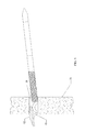
- FIG. 3 illustrates the cross bar and stem body of the anchor stem structure of the hollow wall anchor being inserted into a drilled hole in a plasterboard of a hollow wall in accordance with an embodiment of the presently claimed invention
- FIG. 4 illustrates the stem body of the anchor stem structure of the hollow wall anchor being inserted into the tube of the cleat in accordance with an embodiment of the presently claimed invention
- FIG. 5 illustrates the hollow wall anchor being secured in the drilled hole of the plasterboard of the hollow wall in accordance with an embodiment of the presently claimed invention
- FIG. 6A illustrates a hollow wall anchor assembly in the drilled hole of the plasterboard of the hollow wall after its installation is completed in accordance with an embodiment of the presently claimed invention
- FIG. 6B illustrates a hook used as part of the hollow wall anchor assembly.
- the rapid mounting hollow wall anchor comprises a T-shaped anchor structure.
- the anchor structure comprises a stem body ( 01 ), a cross bar ( 02 ), a cross bar hinge ( 03 ) connecting the cross bar ( 02 ) to an elastic expansion-tension element ( 04 ) which is connecting to one end of the stem body ( 01 ), one or more latching cogs ( 05 ) on at least a portion of the stem body ( 01 ), and a pulling-slot ( 06 ) in at least a portion of the stem body ( 01 ) distal from the cross bar ( 02 ).
- the pulling-slot ( 06 ) is an opening that allows a pulling bar to be inserted through there within.
- the stem body ( 01 ) is flexible. At its normal un-bended position, the cross bar ( 02 ) is substantially perpendicular to the stem body ( 01 ), thus forming a T-shaped structure.
- the cross bar hinge ( 03 ) allows the cross bar ( 02 ) to be bended at least 90 degree from its normal position. When bended 90 degree, the cross bar ( 02 ) becomes approximately parallel to the stem body ( 01 ), making the anchor structure a strait bar for insertion into a drilled hole in a plasterboard of a hollow wall.
- the cross bar hinge ( 03 ) is made of elastic material such that when the cross bar ( 02 ) is bended, the cross bar hinge ( 03 ) is resistive and coiled or stretched.
- the cross bar hinge ( 03 ) includes an elastic mean to provide the resistive force.
- the rapid mounting hollow wall anchor further comprises a cleat.
- the cleat comprises a tube ( 10 ). Inside the tube ( 10 ) is an anchor stem through passage ( 11 ). Near or at one end of the tube is a flange ( 12 ).
- a flange 12
- the guides or threads ( 13 ) provide additional contact surface and hence fiction and securing lateral force against the interior surface of a drilled hole in a plasterboard when the tube ( 10 ) is inserted into the drilled hole.
- the preferred embodiment of the tube ( 10 ) is cylindrical in shape for fitting conventionally drilled holes.
- flange ( 12 ) can be made to have a groove ( 15 ) or hook on where objects can be hung.
- the flange ( 12 ) can also adopt various shapes according to the user's needs; for instance, a rope pulley and a disk with a hook.
- the hole ( 20 ) should be having a diameter of approximately the same as the outer diameter of the tube ( 10 ) of the cleat. Bend the cross bar ( 02 ) for insertion into the drilled hole ( 20 ) as shown in FIG. 3 .
- the cross bar ( 02 ) is to be inserted first. Once the cross bar ( 02 ) is fully inserted into the drill hole ( 20 ) and that the cross bar resumes its normal position in the cavity of the hollow wall and behind the back of the plasterboard ( 21 ), pull on to the stem away from the wall until cross bar ( 02 ) catches the rear surface of the plasterboard ( 21 ).
- a pulling bar ( 30 ) can be used as a gripping handle. To use, insert the pulling bar ( 30 ) through the pulling-slot ( 06 ) in the stem body ( 01 ) such that the stem body ( 01 ) is engaged with the pulling bar ( 30 ) at its midpoint. Any long and slim rigid object that can be inserted through the pulling-slot ( 06 ), such as a screwdriver, can be used in place of the pulling bar ( 30 ).
- a hook ( 40 ) can be held and sandwiched between the flange ( 12 ) of the cleat and the surface of the plasterboard ( 21 ).
- the hook ( 40 ) has a hole with a diameter slightly larger than the outer diameter of the tube ( 10 ).
- the tube ( 10 ) is to be fitted within the hole of the hook ( 40 ) before inserting the stem body ( 01 ) through the anchor stem through passage ( 11 ).
- the rapid mounting hollow wall anchor could be removed by unlocking the latching cogs ( 05 ) on the anchor stem body ( 01 ) from the latching teeth ( 15 ) of the cleat using a sharp pointed tool such as awl to push the latching teeth ( 15 ) sideway away from the latching cogs ( 05 ). Unlocking the latching cogs ( 05 ) from the latching teeth ( 15 ) releases the anchor structure from the cleat. The anchor structure could be pushed in to drop into the hollow space behind the plasterboard ( 21 ), and the cleat can be pulled out from the drilled hole ( 20 ).
- the tube ( 10 ) of the cleat has a plurality of ridges on its exterior surface.
- the ridges are spaced by unit length for measurement to aid the cutting of the tube ( 10 ) for matching the length of the tube ( 10 ) to the thickness of the plasterboard.
Landscapes
- Engineering & Computer Science (AREA)
- General Engineering & Computer Science (AREA)
- Mechanical Engineering (AREA)
- Piles And Underground Anchors (AREA)
- Joining Of Building Structures In Genera (AREA)
- Dowels (AREA)
Abstract
Description
Claims (5)
Priority Applications (4)
| Application Number | Priority Date | Filing Date | Title |
|---|---|---|---|
| US14/481,863 US9273710B1 (en) | 2014-09-09 | 2014-09-09 | Rapid mounting hollow wall anchor |
| PCT/CN2015/071496 WO2016037458A1 (en) | 2014-09-09 | 2015-01-23 | Rapid mounting hallow wall anchor |
| CN201510325968.6A CN106193364B (en) | 2014-09-09 | 2015-06-12 | Quick-installed hollow joist anchor |
| TW104129829A TWI579468B (en) | 2014-09-09 | 2015-09-09 | Rapid mounting hallow wall anchor |
Applications Claiming Priority (1)
| Application Number | Priority Date | Filing Date | Title |
|---|---|---|---|
| US14/481,863 US9273710B1 (en) | 2014-09-09 | 2014-09-09 | Rapid mounting hollow wall anchor |
Publications (2)
| Publication Number | Publication Date |
|---|---|
| US9273710B1 true US9273710B1 (en) | 2016-03-01 |
| US20160069368A1 US20160069368A1 (en) | 2016-03-10 |
Family
ID=55359882
Family Applications (1)
| Application Number | Title | Priority Date | Filing Date |
|---|---|---|---|
| US14/481,863 Expired - Fee Related US9273710B1 (en) | 2014-09-09 | 2014-09-09 | Rapid mounting hollow wall anchor |
Country Status (4)
| Country | Link |
|---|---|
| US (1) | US9273710B1 (en) |
| CN (1) | CN106193364B (en) |
| TW (1) | TWI579468B (en) |
| WO (1) | WO2016037458A1 (en) |
Cited By (4)
| Publication number | Priority date | Publication date | Assignee | Title |
|---|---|---|---|---|
| US20160280525A1 (en) * | 2015-03-27 | 2016-09-29 | Altec Industries, Inc. | Liner retention system for an aerial device |
| US10914334B2 (en) * | 2018-03-30 | 2021-02-09 | Food Grade Solutions, Llc | Wall mounting assembly |
| US11428255B2 (en) | 2018-03-30 | 2022-08-30 | Food Grade Solutions, Llc | Wall mounting assembly |
| US11732741B2 (en) * | 2019-12-18 | 2023-08-22 | 1552818 Ontario Limited | Ratchet toggle connector |
Families Citing this family (1)
| Publication number | Priority date | Publication date | Assignee | Title |
|---|---|---|---|---|
| TWI717967B (en) * | 2020-01-09 | 2021-02-01 | 宜臻富有限公司 | Cable tie |
Citations (1)
| Publication number | Priority date | Publication date | Assignee | Title |
|---|---|---|---|---|
| US20080253860A1 (en) * | 2005-03-21 | 2008-10-16 | Cobra Fixations Cie Ltee - Cobra Anchors Co., Ltd. | Anchor Assembly for Fastener |
Family Cites Families (17)
| Publication number | Priority date | Publication date | Assignee | Title |
|---|---|---|---|---|
| GB191205727A (en) * | 1912-03-07 | 1912-11-07 | John Francis Smith | Improvements in Security Bolts for use in connection with Pneumatic Tyres. |
| US3343442A (en) * | 1965-08-13 | 1967-09-26 | United Carr Inc | Vibration damping fastener |
| US4573844A (en) * | 1983-11-25 | 1986-03-04 | Smith Gareth J | Anchoring bolt device |
| GB8519917D0 (en) * | 1985-08-08 | 1985-09-18 | Birchwood Products Ltd | Plugs |
| US4943253A (en) * | 1989-03-23 | 1990-07-24 | Dry Dock Industries, Inc. | Axial immobile fastener-receiving member |
| US4993901A (en) * | 1990-02-26 | 1991-02-19 | Mechanical Plastics Corp. | Over-center hollow wall anchor with enhanced holding strength |
| AUPN159095A0 (en) * | 1995-03-07 | 1995-03-30 | Pecotic, Vicko | Fixing device |
| JP2002130230A (en) * | 2000-10-23 | 2002-05-09 | Wakai & Co Ltd | Anchor device |
| EP1518976A1 (en) * | 2003-09-26 | 2005-03-30 | André Nicolet | Post with barbed anchors |
| US8764364B2 (en) * | 2004-03-24 | 2014-07-01 | Illinois Tool Works Inc. | System and methods for wall and ceiling fastening |
| US20060062650A1 (en) * | 2004-09-20 | 2006-03-23 | The Boeing Company | Hybrid fastener apparatus and method for fastening |
| CA2502008A1 (en) * | 2005-03-21 | 2006-09-21 | Cobra Fixations Cie Ltee - Cobra Anchors Co. Ltd. | Anchor with toggle for hollow walls |
| US8197169B2 (en) * | 2008-03-03 | 2012-06-12 | Illinois Tool Works Inc. | Hollow wall fastener |
| GB0914172D0 (en) * | 2009-08-13 | 2009-09-16 | Collins John | Fixing |
| DE102010002847A1 (en) * | 2010-03-15 | 2011-09-15 | Newfrey Llc | Blind rivet with a plastic rivet body |
| CN201671932U (en) * | 2010-05-12 | 2010-12-15 | 盟和产业株式会社 | Part installation structure for installing parts on hollow plastic sandwich plate |
| CN203384175U (en) * | 2013-06-26 | 2014-01-08 | 赵永军 | Expansion bolt |
-
2014
- 2014-09-09 US US14/481,863 patent/US9273710B1/en not_active Expired - Fee Related
-
2015
- 2015-01-23 WO PCT/CN2015/071496 patent/WO2016037458A1/en active Application Filing
- 2015-06-12 CN CN201510325968.6A patent/CN106193364B/en active Active
- 2015-09-09 TW TW104129829A patent/TWI579468B/en not_active IP Right Cessation
Patent Citations (1)
| Publication number | Priority date | Publication date | Assignee | Title |
|---|---|---|---|---|
| US20080253860A1 (en) * | 2005-03-21 | 2008-10-16 | Cobra Fixations Cie Ltee - Cobra Anchors Co., Ltd. | Anchor Assembly for Fastener |
Cited By (5)
| Publication number | Priority date | Publication date | Assignee | Title |
|---|---|---|---|---|
| US20160280525A1 (en) * | 2015-03-27 | 2016-09-29 | Altec Industries, Inc. | Liner retention system for an aerial device |
| US9851048B2 (en) * | 2015-03-27 | 2017-12-26 | Altec Industries, Inc. | Liner retention system for an aerial device |
| US10914334B2 (en) * | 2018-03-30 | 2021-02-09 | Food Grade Solutions, Llc | Wall mounting assembly |
| US11428255B2 (en) | 2018-03-30 | 2022-08-30 | Food Grade Solutions, Llc | Wall mounting assembly |
| US11732741B2 (en) * | 2019-12-18 | 2023-08-22 | 1552818 Ontario Limited | Ratchet toggle connector |
Also Published As
| Publication number | Publication date |
|---|---|
| US20160069368A1 (en) | 2016-03-10 |
| WO2016037458A1 (en) | 2016-03-17 |
| CN106193364A (en) | 2016-12-07 |
| CN106193364B (en) | 2019-03-01 |
| TWI579468B (en) | 2017-04-21 |
| TW201610307A (en) | 2016-03-16 |
Similar Documents
| Publication | Publication Date | Title |
|---|---|---|
| US9273710B1 (en) | Rapid mounting hollow wall anchor | |
| EP3423741B1 (en) | Fixing apparatus and method | |
| CA2611510C (en) | Three piece garage hook | |
| US6318941B1 (en) | Wall anchor | |
| EP3036444B1 (en) | Improvements in and relating to pipe support systems | |
| US20120042607A1 (en) | Masonry Insulation and Siding Connector | |
| US8814485B2 (en) | Hollow wall mounting assembly | |
| US10837480B2 (en) | Hollow wall anchor | |
| US8979459B2 (en) | Combination hanger fastener | |
| CA2728241A1 (en) | Improved hollow wall fastener | |
| US10208780B1 (en) | Line mounting device | |
| US20050069398A1 (en) | Fastener | |
| US20140102040A1 (en) | Wall anchor assembly and method of installation | |
| US6318704B1 (en) | Method for threading wire through a wall or partition | |
| JP6373672B2 (en) | Sleeve fixing device and sleeve fixing structure | |
| US20100329819A1 (en) | Hollow wall fastener | |
| TW201712193A (en) | Anchor bolt having reverse-rotation preventing mechanism wherein the coil spring (17) allows the screw rod (4) to normally rotate for enabling the conical component (7) to be moved towards the installation hole (2) and the screw rod (4) is prevented from reversely rotating | |
| WO2020070478A1 (en) | Self supporting hook | |
| GB2501794A (en) | Anchor suitable for securing wires to a ceiling or decking | |
| JP6172635B2 (en) | Handrail mounting structure | |
| WO2018091868A1 (en) | Fixing device and method of manufacture thereof | |
| JP5265802B1 (en) | Fixture | |
| KR20230056831A (en) | Drywall anchor with fully recessed guide sleeve | |
| US20160344173A1 (en) | Structural insert and method of use | |
| JP6664934B2 (en) | anchor |
Legal Events
| Date | Code | Title | Description |
|---|---|---|---|
| AS | Assignment |
Owner name: NEO MECHANICS LIMITED, HONG KONG Free format text: ASSIGNMENT OF ASSIGNORS INTEREST;ASSIGNOR:CHANG, KYONG TAE;REEL/FRAME:033704/0602 Effective date: 20140907 Owner name: NEO MECHANICS LIMITED, HONG KONG Free format text: ASSIGNMENT OF ASSIGNORS INTEREST;ASSIGNOR:CHANG, KYONG TAE;REEL/FRAME:033704/0568 Effective date: 20140907 |
|
| ZAAA | Notice of allowance and fees due |
Free format text: ORIGINAL CODE: NOA |
|
| ZAAB | Notice of allowance mailed |
Free format text: ORIGINAL CODE: MN/=. |
|
| STCF | Information on status: patent grant |
Free format text: PATENTED CASE |
|
| MAFP | Maintenance fee payment |
Free format text: PAYMENT OF MAINTENANCE FEE, 4TH YR, SMALL ENTITY (ORIGINAL EVENT CODE: M2551); ENTITY STATUS OF PATENT OWNER: SMALL ENTITY Year of fee payment: 4 |
|
| FEPP | Fee payment procedure |
Free format text: MAINTENANCE FEE REMINDER MAILED (ORIGINAL EVENT CODE: REM.); ENTITY STATUS OF PATENT OWNER: SMALL ENTITY |
|
| LAPS | Lapse for failure to pay maintenance fees |
Free format text: PATENT EXPIRED FOR FAILURE TO PAY MAINTENANCE FEES (ORIGINAL EVENT CODE: EXP.); ENTITY STATUS OF PATENT OWNER: SMALL ENTITY |
|
| STCH | Information on status: patent discontinuation |
Free format text: PATENT EXPIRED DUE TO NONPAYMENT OF MAINTENANCE FEES UNDER 37 CFR 1.362 |