US9195238B2 - Waste water vessels with multiple valved chambers, and associated systems and methods - Google Patents
Waste water vessels with multiple valved chambers, and associated systems and methods Download PDFInfo
- Publication number
- US9195238B2 US9195238B2 US13/830,569 US201313830569A US9195238B2 US 9195238 B2 US9195238 B2 US 9195238B2 US 201313830569 A US201313830569 A US 201313830569A US 9195238 B2 US9195238 B2 US 9195238B2
- Authority
- US
- United States
- Prior art keywords
- chamber
- pressure
- valve
- liquid
- coupled
- Prior art date
- Legal status (The legal status is an assumption and is not a legal conclusion. Google has not performed a legal analysis and makes no representation as to the accuracy of the status listed.)
- Expired - Fee Related, expires
Links
Images


Classifications
-
- G—PHYSICS
- G05—CONTROLLING; REGULATING
- G05D—SYSTEMS FOR CONTROLLING OR REGULATING NON-ELECTRIC VARIABLES
- G05D9/00—Level control, e.g. controlling quantity of material stored in vessel
-
- A—HUMAN NECESSITIES
- A47—FURNITURE; DOMESTIC ARTICLES OR APPLIANCES; COFFEE MILLS; SPICE MILLS; SUCTION CLEANERS IN GENERAL
- A47L—DOMESTIC WASHING OR CLEANING; SUCTION CLEANERS IN GENERAL
- A47L11/00—Machines for cleaning floors, carpets, furniture, walls, or wall coverings
- A47L11/29—Floor-scrubbing machines characterised by means for taking-up dirty liquid
- A47L11/30—Floor-scrubbing machines characterised by means for taking-up dirty liquid by suction
-
- A—HUMAN NECESSITIES
- A47—FURNITURE; DOMESTIC ARTICLES OR APPLIANCES; COFFEE MILLS; SPICE MILLS; SUCTION CLEANERS IN GENERAL
- A47L—DOMESTIC WASHING OR CLEANING; SUCTION CLEANERS IN GENERAL
- A47L9/00—Details or accessories of suction cleaners, e.g. mechanical means for controlling the suction or for effecting pulsating action; Storing devices specially adapted to suction cleaners or parts thereof; Carrying-vehicles specially adapted for suction cleaners
- A47L9/28—Installation of the electric equipment, e.g. adaptation or attachment to the suction cleaner; Controlling suction cleaners by electric means
-
- B—PERFORMING OPERATIONS; TRANSPORTING
- B08—CLEANING
- B08B—CLEANING IN GENERAL; PREVENTION OF FOULING IN GENERAL
- B08B3/00—Cleaning by methods involving the use or presence of liquid or steam
-
- C—CHEMISTRY; METALLURGY
- C02—TREATMENT OF WATER, WASTE WATER, SEWAGE, OR SLUDGE
- C02F—TREATMENT OF WATER, WASTE WATER, SEWAGE, OR SLUDGE
- C02F1/00—Treatment of water, waste water, or sewage
-
- E—FIXED CONSTRUCTIONS
- E01—CONSTRUCTION OF ROADS, RAILWAYS, OR BRIDGES
- E01H—STREET CLEANING; CLEANING OF PERMANENT WAYS; CLEANING BEACHES; DISPERSING OR PREVENTING FOG IN GENERAL CLEANING STREET OR RAILWAY FURNITURE OR TUNNEL WALLS
- E01H1/00—Removing undesirable matter from roads or like surfaces, with or without moistening of the surface
- E01H1/08—Pneumatically dislodging or taking-up undesirable matter or small objects; Drying by heat only or by streams of gas; Cleaning by projecting abrasive particles
-
- E—FIXED CONSTRUCTIONS
- E03—WATER SUPPLY; SEWERAGE
- E03F—SEWERS; CESSPOOLS
- E03F1/00—Methods, systems, or installations for draining-off sewage or storm water
- E03F1/006—Pneumatic sewage disposal systems; accessories specially adapted therefore
-
- G—PHYSICS
- G05—CONTROLLING; REGULATING
- G05D—SYSTEMS FOR CONTROLLING OR REGULATING NON-ELECTRIC VARIABLES
- G05D9/00—Level control, e.g. controlling quantity of material stored in vessel
- G05D9/12—Level control, e.g. controlling quantity of material stored in vessel characterised by the use of electric means
-
- C—CHEMISTRY; METALLURGY
- C02—TREATMENT OF WATER, WASTE WATER, SEWAGE, OR SLUDGE
- C02F—TREATMENT OF WATER, WASTE WATER, SEWAGE, OR SLUDGE
- C02F2103/00—Nature of the water, waste water, sewage or sludge to be treated
- C02F2103/001—Runoff or storm water
-
- C—CHEMISTRY; METALLURGY
- C02—TREATMENT OF WATER, WASTE WATER, SEWAGE, OR SLUDGE
- C02F—TREATMENT OF WATER, WASTE WATER, SEWAGE, OR SLUDGE
- C02F2201/00—Apparatus for treatment of water, waste water or sewage
- C02F2201/002—Construction details of the apparatus
- C02F2201/003—Coaxial constructions, e.g. a cartridge located coaxially within another
-
- C—CHEMISTRY; METALLURGY
- C02—TREATMENT OF WATER, WASTE WATER, SEWAGE, OR SLUDGE
- C02F—TREATMENT OF WATER, WASTE WATER, SEWAGE, OR SLUDGE
- C02F2201/00—Apparatus for treatment of water, waste water or sewage
- C02F2201/002—Construction details of the apparatus
- C02F2201/004—Seals, connections
-
- C—CHEMISTRY; METALLURGY
- C02—TREATMENT OF WATER, WASTE WATER, SEWAGE, OR SLUDGE
- C02F—TREATMENT OF WATER, WASTE WATER, SEWAGE, OR SLUDGE
- C02F2201/00—Apparatus for treatment of water, waste water or sewage
- C02F2201/002—Construction details of the apparatus
- C02F2201/005—Valves
-
- C—CHEMISTRY; METALLURGY
- C02—TREATMENT OF WATER, WASTE WATER, SEWAGE, OR SLUDGE
- C02F—TREATMENT OF WATER, WASTE WATER, SEWAGE, OR SLUDGE
- C02F2209/00—Controlling or monitoring parameters in water treatment
- C02F2209/005—Processes using a programmable logic controller [PLC]
-
- C—CHEMISTRY; METALLURGY
- C02—TREATMENT OF WATER, WASTE WATER, SEWAGE, OR SLUDGE
- C02F—TREATMENT OF WATER, WASTE WATER, SEWAGE, OR SLUDGE
- C02F2301/00—General aspects of water treatment
- C02F2301/02—Fluid flow conditions
- C02F2301/026—Spiral, helicoidal, radial
-
- C—CHEMISTRY; METALLURGY
- C02—TREATMENT OF WATER, WASTE WATER, SEWAGE, OR SLUDGE
- C02F—TREATMENT OF WATER, WASTE WATER, SEWAGE, OR SLUDGE
- C02F2301/00—General aspects of water treatment
- C02F2301/06—Pressure conditions
- C02F2301/063—Underpressure, vacuum
-
- C—CHEMISTRY; METALLURGY
- C02—TREATMENT OF WATER, WASTE WATER, SEWAGE, OR SLUDGE
- C02F—TREATMENT OF WATER, WASTE WATER, SEWAGE, OR SLUDGE
- C02F2301/00—General aspects of water treatment
- C02F2301/08—Multistage treatments, e.g. repetition of the same process step under different conditions
-
- Y—GENERAL TAGGING OF NEW TECHNOLOGICAL DEVELOPMENTS; GENERAL TAGGING OF CROSS-SECTIONAL TECHNOLOGIES SPANNING OVER SEVERAL SECTIONS OF THE IPC; TECHNICAL SUBJECTS COVERED BY FORMER USPC CROSS-REFERENCE ART COLLECTIONS [XRACs] AND DIGESTS
- Y10—TECHNICAL SUBJECTS COVERED BY FORMER USPC
- Y10T—TECHNICAL SUBJECTS COVERED BY FORMER US CLASSIFICATION
- Y10T137/00—Fluid handling
- Y10T137/0318—Processes
-
- Y—GENERAL TAGGING OF NEW TECHNOLOGICAL DEVELOPMENTS; GENERAL TAGGING OF CROSS-SECTIONAL TECHNOLOGIES SPANNING OVER SEVERAL SECTIONS OF THE IPC; TECHNICAL SUBJECTS COVERED BY FORMER USPC CROSS-REFERENCE ART COLLECTIONS [XRACs] AND DIGESTS
- Y10—TECHNICAL SUBJECTS COVERED BY FORMER USPC
- Y10T—TECHNICAL SUBJECTS COVERED BY FORMER US CLASSIFICATION
- Y10T137/00—Fluid handling
- Y10T137/7287—Liquid level responsive or maintaining systems
-
- Y—GENERAL TAGGING OF NEW TECHNOLOGICAL DEVELOPMENTS; GENERAL TAGGING OF CROSS-SECTIONAL TECHNOLOGIES SPANNING OVER SEVERAL SECTIONS OF THE IPC; TECHNICAL SUBJECTS COVERED BY FORMER USPC CROSS-REFERENCE ART COLLECTIONS [XRACs] AND DIGESTS
- Y10—TECHNICAL SUBJECTS COVERED BY FORMER USPC
- Y10T—TECHNICAL SUBJECTS COVERED BY FORMER US CLASSIFICATION
- Y10T137/00—Fluid handling
- Y10T137/8593—Systems
- Y10T137/85978—With pump
- Y10T137/86035—Combined with fluid receiver
-
- Y—GENERAL TAGGING OF NEW TECHNOLOGICAL DEVELOPMENTS; GENERAL TAGGING OF CROSS-SECTIONAL TECHNOLOGIES SPANNING OVER SEVERAL SECTIONS OF THE IPC; TECHNICAL SUBJECTS COVERED BY FORMER USPC CROSS-REFERENCE ART COLLECTIONS [XRACs] AND DIGESTS
- Y10—TECHNICAL SUBJECTS COVERED BY FORMER USPC
- Y10T—TECHNICAL SUBJECTS COVERED BY FORMER US CLASSIFICATION
- Y10T137/00—Fluid handling
- Y10T137/8593—Systems
- Y10T137/86187—Plural tanks or compartments connected for serial flow
- Y10T137/86196—Separable with valved-connecting passage
-
- Y—GENERAL TAGGING OF NEW TECHNOLOGICAL DEVELOPMENTS; GENERAL TAGGING OF CROSS-SECTIONAL TECHNOLOGIES SPANNING OVER SEVERAL SECTIONS OF THE IPC; TECHNICAL SUBJECTS COVERED BY FORMER USPC CROSS-REFERENCE ART COLLECTIONS [XRACs] AND DIGESTS
- Y10—TECHNICAL SUBJECTS COVERED BY FORMER USPC
- Y10T—TECHNICAL SUBJECTS COVERED BY FORMER US CLASSIFICATION
- Y10T137/00—Fluid handling
- Y10T137/8593—Systems
- Y10T137/86187—Plural tanks or compartments connected for serial flow
- Y10T137/8622—Plural top-to-bottom connected tanks
-
- Y—GENERAL TAGGING OF NEW TECHNOLOGICAL DEVELOPMENTS; GENERAL TAGGING OF CROSS-SECTIONAL TECHNOLOGIES SPANNING OVER SEVERAL SECTIONS OF THE IPC; TECHNICAL SUBJECTS COVERED BY FORMER USPC CROSS-REFERENCE ART COLLECTIONS [XRACs] AND DIGESTS
- Y10—TECHNICAL SUBJECTS COVERED BY FORMER USPC
- Y10T—TECHNICAL SUBJECTS COVERED BY FORMER US CLASSIFICATION
- Y10T137/00—Fluid handling
- Y10T137/8593—Systems
- Y10T137/86187—Plural tanks or compartments connected for serial flow
- Y10T137/86228—With communicating opening in common walls of tanks or compartments
Definitions
- the present disclosure is directed generally to waste water vessels with multiple valved chambers, and associated systems and methods.
- Existing commercial systems for cleaning flooring surfaces and/or extracting water from water-damaged buildings include truck, van or trailer based devices. These devices typically include a supply water tank that supplies clean, (optionally) heated water and detergent to a hand held wand. An operator moves the wand over the floor while the wand directs the heated cleaning fluid over the floor and removes spent cleaning fluid and dirt from the floor.
- Such systems typically include a waste tank that receives the post-cleaning fluid and dirt extracted by the wand.
- a pump pressurizes the water supplied to the wand, and a blower draws a vacuum on the waste tank so as to draw the waste water and dirt from the wand into the waste tank.
- the pump and blower can be driven by the vehicle's engine, or, more typically, with a separate internal combustion engine carried by the vehicle.
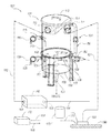
- FIG. 1 is a partially transparent, isometric illustration of a system for handling waste water in accordance with an embodiment of the present technology.
- FIG. 2 is an isometric illustration of a representative vacuum source configured in accordance with an embodiment of the present technology.
- FIG. 3 is a partially schematic illustration of portions of a system for handling waste water in accordance with an embodiment of the present technology.
- FIG. 4 is a partially schematic, cross-sectional illustration of particular features of an embodiment of the system shown in FIG. 3 .
- the present technology is directed generally to waste water vessels with multiple valved chambers, and associated systems and methods. Specific details of several embodiments of the disclosure are described below with reference to particular configurations. In other embodiments, aspects of the disclosed technology can have other arrangements. Several details disclosing structures or processes that are well-known and often associated with these types of systems, but that may unnecessarily obscure some significant aspects of the disclosure, are not set forth in the following description for purposes of clarity. Moreover, although the following disclosure sets forth several embodiments of different aspects of the disclosed technology, several other embodiments can have different configurations and/or different components than those described in this section. Accordingly, the present technology may have other embodiments with additional elements not described below with reference to FIGS. 1-4 , and/or without several of the elements described below with reference to FIGS. 1-4 .
- FIG. 1 A block diagram illustrating an exemplary computing environment in accordance with the present technology.
- FIG. 1 A block diagram illustrating an exemplary computing environment in accordance with the present technology.
- FIG. 1 A block diagram illustrating an exemplary computing environment in accordance with the present technology.
- FIG. 1 A block diagram illustrating an exemplary computing environment in accordance with the present technology.
- FIG. 1 A block diagram illustrating an exemplary computing environment in accordance with the present technology described below.
- FIG. 1 A block diagram illustrating an exemplary computing environment in accordance with the present technology.
- FIG. 1 A block diagram illustrating an exemplary computing environment in accordance with the present technology.
- FIG. 1 A block diagram illustrating an exemplary computing environment in accordance with the present technology.
- FIG. 1 A block diagram illustrating an exemplary computing environment in accordance with the present technology.
- FIG. 1 A block diagram illustrating an exemplary computing environment in accordance with the present technology.
- FIG. 1 A block diagram illustrating an exemplary computing environment in accordance with the present technology.
- the technology can also be practiced in distributed environments, where tasks or modules are performed by remote processing devices that are linked through a communications network.
- program modules or subroutines may be located in local and remote memory storage devices.
- aspects of the technology described below may be stored or distributed on computer-readable media, including magnetic or optically readable or removable computer disks, as well as distributed electronically over networks. Data structures and transmissions of data particular to aspects of the technology are also encompassed within the scope of the certain embodiments of the technology, while other embodiments do not include data structures and transmissions of data.
- FIG. 1 is a partially schematic, partially transparent illustration of a system 100 having a vessel 101 configured in accordance with a particular embodiment of the present technology.
- the system 100 also includes a floor tool 180 (e.g., a wand) that moves along a floor or other surface 190 and removes liquid, e.g., water.
- the water can be pre-existing water (e.g., floodwater) and/or cleaning water provided by a water supply 170 via a clean water line 171 .
- the vessel 101 includes a first or upper chamber 110 and a second or lower chamber 130 .
- the first chamber 110 receives waste fluid via a waste intake port 111 that is coupled to the floor tool 180 with a waste water line 181 .
- the second chamber 130 delivers the collected waste fluid through an exit port 133 and a second chamber outlet valve 134 , e.g., to a drain line, large storage tank, or final disposal site.
- a second chamber outlet valve 134 e.g., to a drain line, large storage tank, or final disposal site.
- the first and second chambers 110 , 130 are coupled together so as to operate simultaneously. Accordingly, the vessel 101 can be drained via the second chamber outlet valve 134 at the same time it receives waste fluid via the waste intake port 111 .
- the first chamber 110 includes a vacuum outlet port 112 .
- the vacuum outlet port 112 can be coupled to a vacuum source 160 having a vacuum inlet 161 . Accordingly, the vacuum source 160 can draw a vacuum on the interior region of the first chamber 110 via a vacuum line 162 . The vacuum created by the vacuum source 160 on the interior region of the first chamber 110 in turn draws waste fluid through the waste intake port 111 .
- Waste water entering the waste intake port 111 can be directed in a circumferential, downward direction, so as to swirl or otherwise circulate on its way downwardly through the first chamber 110 .
- One or more baffles 114 prevent or at least restrict the liquid entering the waste intake port 111 from being sucked into the vacuum outlet port 112 . Accordingly, this arrangement allows air to be withdrawn through the vacuum outlet port 112 without also entraining liquids and/or solids entering the waste intake port 111 .
- a chamber divider 102 can be positioned between the first chamber 110 and the second chamber 130 . Accordingly, the chamber divider can include a single wall (as shown in FIG. 1 ) or multiple walls (as described later and shown in FIGS. 3 and 4 ).
- a first chamber outlet valve 117 can be coupled to an inlet port 131 of the second chamber 130 to regulate the fluid communication between the first chamber 110 and the second chamber 130 through the chamber divider 102 .
- a chamber connecting passage 150 can be connected between the first and second chambers 110 , 130 to selectively equalize the pressure between the two chambers. Accordingly, the chamber connecting passage 150 can include a connecting passage valve 151 .
- the connecting passage valve 151 allows the pressures within the first and second chambers 110 , 130 to equalize, and in a second or closed position or state, the connecting passage valve 151 isolates the two chambers from each other, thus allowing different pressures to develop in each chamber.
- the second chamber 130 can also include a float switch 135 or other liquid quantity detector having wiring 136 or other communication features that, among other functions, allows the float switch 135 to communicate with (e.g., control) the connecting passage valve 151 .
- the float switch 135 can be tripped or activated when the fluid level within the second chamber 130 exceeds a pre-determined value.
- the second chamber 130 can further include an ambient/pressure port 132 (e.g., a pressure inlet port) and an ambient/pressure valve 152 (or other liquid outlet valve) that regulates fluid communication between the second chamber 130 and the ambient environment or a pressure source.
- the ambient/pressure valve 152 can operate in conjunction with but out of phase with the connecting passage valve 151 , as will be described further below.
- the first chamber outlet valve 117 and the second chamber outlet valve 134 are each configured to operate as a check valve. Accordingly, the first chamber outlet valve 117 is open when the pressure in the first chamber 110 is equal to or exceeds the pressure in the second chamber 130 . The second chamber outlet valve 134 is open when the pressure within the second chamber 130 is equal to or exceeds the pressure outside the vessel 101 .
- the user activates the vacuum source 160 to draw a vacuum on the first chamber 110 via the vacuum line 162 .
- the user opens the connecting passage valve 151 (if it is not automatically opened already) so as to equalize the pressures in the first chamber 110 and the second chamber 130 .
- the user closes the ambient/pressure valve 152 (if it is not automatically closed already).
- the user then operates the floor tool 180 to remove pre-existing water and/or debris, and/or waste water and debris resulting from cleaning the surface 190 .
- the vacuum in the first chamber 110 draws the waste stream through the waste intake port 111 via the waste water line 181 .
- As water accumulates in the first chamber 110 it passes through the first chamber outlet valve 117 into the second chamber 130 under the force of gravity.
- the vacuum in the second chamber 130 prevents the water accumulating in the second chamber 130 from passing out of the second chamber 130 via the second chamber outlet valve 134 and into a drain line, large storage tank, and/or other disposal facility (not shown in FIG. 1 ).
- Waste water accumulates in the second chamber 130 until the rising water trips or activates the float switch 135 .
- the float switch 135 When the float switch 135 is tripped or activated, it closes the connecting passage valve 151 to allow different pressures to develop in the first chamber 110 and the second chamber 130 , and opens the ambient/pressure valve 152 . Accordingly, with the connecting passage valve 151 closed, the vacuum source 160 can continue to draw a vacuum on the first chamber 110 without affecting the pressure in the second chamber 130 . As a result, the user can continue to operate the floor tool 180 and provide waste water to the first chamber 110 while the second chamber 130 drains.
- exposing the second chamber 130 to ambient pressure via the ambient/pressure port 132 is sufficient to remove the waste water accumulated in the second chamber 130 .
- the ambient/pressure port 132 can be coupled to a source of air at an elevated pressure to expedite the process of removing the waste water from the second chamber 130 .
- the ambient/pressure port 132 is coupled to a blower or pressure outlet 163 of the vacuum source 160 with a blower line 164 . Accordingly, the vacuum source 160 can provide two functions: (1) drawing a vacuum on the first chamber 110 and (2) pressurizing the second chamber 130 with the air withdrawn from the first chamber 110 .
- the float switch 135 de-activates or otherwise changes state, causing the connecting passage valve 151 to open and the ambient/pressure valve 152 to close. Accordingly, the chamber connecting passage 150 once again equalizes the pressures in the first and second chambers 110 , 130 .
- the foregoing process continues on a cyclic basis, as needed, without interrupting the user's operation of the floor tool 180 .
- the foregoing operations can be executed by a controller 103 that receives inputs 104 and issues commands 105 .
- the controller can include analog and/or digital features and/or instructions for carrying out the foregoing tasks.
- the instructions can take the form of computer-executable instructions carried bt a suitable computer-readable medium.
- a representative liquid quantity detector includes a shut-off valve 115 (e.g., a float valve) located in the first chamber 110 and coupled to a controller or other control device with wiring 116 .
- the shut-off valve 115 can shut off power to the system 100 or a portion of the system 100 if the water level within the first chamber 110 exceeds a pre-determined level or threshold.
- the second chamber 130 can include an access port 138 having a removable access hatch 137 .
- the access hatch 137 can be used to install the first chamber outlet valve 117 and/or clean the second chamber 130 .
- a lid 113 positioned at (e.g., over) the first chamber 110 can allow access to the first chamber 110 , e.g., for service or cleaning.
- FIG. 2 is a partially schematic isometric illustration of a representative vacuum source 160 , illustrating the vacuum inlet 161 .
- the same device provides both vacuum for the first chamber 110 described above with reference to FIG. 1 , and pressure for the second chamber 130 , also described above with reference to FIG. 1 , though the blower outlet 163 ( FIG. 1 ) is not visible in FIG. 2 .
- these functions can be provided by separate devices.
- FIG. 3 is a partially schematic illustration of portions of a system 300 that include several features identical or similar to those described above with reference to FIG. 1 , and manufactured in accordance with a particular embodiment of the present technology.
- the system 300 includes a rotomolded vessel 301 formed from a plastic or other moldable material.
- the vessel 301 can accordingly include a rotomolded first chamber 310 and second chamber 330 .
- both chambers 310 , 330 can be simultaneously formed as a monolithic structure and in other embodiments, each chamber can be individually formed.
- the vessel 301 can also include a chamber divider 302 .
- the chamber divider 302 can have an upwardly bowed shape to withstand the higher pressure typically produced within the second chamber 330 .
- Each of the first and second chambers 310 , 330 can have ribs 303 or other elements that strengthen or reinforce the vessel 301 .
- the vessel 301 can be formed from other materials and/or with other techniques.
- the vessel 301 can be formed from sheet metal.
- the walls of the vessel 301 can be thick enough not to require the ribs 303 .
- FIG. 4 is a partially schematic, cross-sectional illustration of an embodiment of the vessel 301 shown in FIG. 3 .
- FIG. 4 illustrates further details of the baffle 114 , which is arranged to prevent or at least restrict liquid entering the waste intake port 111 from being immediately sucked into the vacuum outlet 112 .
- FIG. 4 also illustrates a representative orientation of the waste intake port 111 , illustrating that it is pointing downwardly (e.g., away from the vacuum outlet port 112 ) and generally tangential to the inner surface of the first chamber 310 , so as to allow waste water to swirl as it descends through the first chamber 310 . This swirling action can facilitate separating air entrained in the waste liquid from the waste liquid itself.
- FIG. 4 also illustrates further details of the second chamber outlet valve 134 .
- the first chamber outlet valve 117 can include similar features. These features can include, for example, a valve entry 438 (e.g., toward an upper end of the valve 134 ) and a valve exit 439 (e.g., toward a lower end of the valve 134 ).
- At least a portion of the second chamber outlet valve 134 can be formed from a flexible material, which in turn defines, at least in part, flexible flaps 440 , illustrated as a first flexible flap 440 a and a second flexible flap 440 b .
- the flexible flaps 440 can be configured to close (e.g., in the manner of a duck's bill) when the pressure at the valve entry 438 is less than the pressure at the valve exit 439 .
- the flexible flaps 440 can open when the pressure at the valve entry 438 is greater than the pressure at the valve exit 439 .
- the size and shape of the second chamber outlet valve 134 and the flexible flaps 440 can be configured to allow particulate matter to pass through the valve 134 , as desired.
- the elevated pressure in the second chamber 130 can operate to remove debris that might otherwise be caught between the surfaces (e.g., the flaps 440 ) of the second chamber valve 134 .
- both the first and second chamber outlet valves 117 , 134 can be configured to allow the valves to close readily under preselected pressure differentials. Accordingly, either or both of the chamber outlet valves can have a duck bill configuration with opposing flexible surfaces that are in surface-to-surface contact when the valve is in the closed state and are spaced apart from each other when the valve is in the open state.
- the swirling action of the water in the first chamber 110 can operate to remove debris that might otherwise be caught between the surfaces (e.g., the flaps 440 ) of the first chamber valve 117 .
- the systems can allow waste liquid to be withdrawn from the collection vessel at the same time the vessel is collecting waste liquid. This in turn can allow the operator to simultaneously drain fluid from the tank and continue filling the tank, increasing the efficiency with which waste water is removed and handled.
- Another feature of at least some of the foregoing embodiments is that the foregoing operation can be conducted independently of any direct interaction or intervention by the operator, except to activate the system.
- the float switch 135 can automatically activate the chamber connecting valve 151 when the fluid level in the second chamber 130 exceeds a pre-determined limit, and can automatically close the chamber connecting valve 151 when the fluid drains from the second chamber 130 .
- the system can include a controller or controller logic carried by the valves and/or by a suitable controller. Still another feature of at least some the foregoing embodiments is that the system can be manufactured at a relatively low cost. In particular, the system can cost less than a pump, which is typically used to evacuate water from a storage tank. In addition, the system can further reduce the cost of operation by increasing the efficiency of the fluid removal process, as described above. Yet another feature of at least some of the foregoing embodiments is that they can eliminate the need for alternating between applying a vacuum source to a collection vessel and applying a pressure source to the collection vessel. Accordingly, the vacuum source can remain coupled to the vacuum outlet port and the pressure source can remain coupled to the second chamber, with the connecting valve, the first chamber valve and/or the second chamber valve being in either the open state or the closed state
- a method in accordance with a particular embodiment includes drawing or instructing drawing of waste water into a first chamber under vacuum while the first chamber and a second chamber have at least approximately the same internal pressure, allowing the waste water to pass from the first chamber to the second chamber while the first chamber has an internal pressure equal to or above an internal pressure in a second chamber, releasably sealing the first chamber from fluid communication with the second chamber, and while the first chamber is sealed from fluid communication with the second chamber, simultaneously adding waste water to the first chamber and removing wastewater from the second chamber.
- a method in accordance with another embodiment includes instructing such a method. Accordingly, any and all methods of use and manufacture disclosed herein also fully disclose and enable corresponding methods of instructing such methods of use and manufacture.
- valves described above may have configurations other than those shown in the Figures.
- the multiple chambers described above can be housed in a single vessel, as shown in FIG. 1 , or in multiple vessels in other embodiments.
- the first and second chambers can be fixed relative to each other in particular embodiments, and movable relative to each other in other embodiments. In at least some cases, the fixed arrangement can make the chambers easier to handle.
- the first and second chambers can be generally cylindrical and, in particular embodiments, co-axial. In other embodiments, the chambers can have other shapes and/or arrangements.
- the cylindrical/co-axial arrangement can make the chambers easier to handle.
- the second chamber outlet valve 134 can be located at or just outside the second chamber 130 , or it can be located more distant from the second chamber 130 , e.g., in or at the end of a drain line.
- Certain aspects of the disclosed technology described in the context of particular embodiments may be combined or eliminated in other embodiments.
- the chambers may be manufactured using techniques other than rotomolding, and certain features (e.g., the access ports described above) can be eliminated.
- advantages associated with certain embodiments of the technology have been described in the context of those embodiments, other embodiments may also exhibit such advantages, and not all embodiments need necessarily exhibit such advantages to fall within the scope of the present technology. Accordingly, the disclosure and associated technology can encompass other embodiments not expressly shown or described herein.
Abstract
Description
Claims (29)
Priority Applications (3)
| Application Number | Priority Date | Filing Date | Title |
|---|---|---|---|
| US13/830,569 US9195238B2 (en) | 2012-06-15 | 2013-03-14 | Waste water vessels with multiple valved chambers, and associated systems and methods |
| PCT/US2013/045947 WO2013188800A1 (en) | 2012-06-15 | 2013-06-14 | Waste water vessels with multiple valved chambers, and associated systems and methods |
| CA2873795A CA2873795C (en) | 2012-06-15 | 2013-06-14 | Waste water vessels with multiple valved chambers, and associated systems and methods |
Applications Claiming Priority (2)
| Application Number | Priority Date | Filing Date | Title |
|---|---|---|---|
| US201261660618P | 2012-06-15 | 2012-06-15 | |
| US13/830,569 US9195238B2 (en) | 2012-06-15 | 2013-03-14 | Waste water vessels with multiple valved chambers, and associated systems and methods |
Publications (2)
| Publication Number | Publication Date |
|---|---|
| US20130333760A1 US20130333760A1 (en) | 2013-12-19 |
| US9195238B2 true US9195238B2 (en) | 2015-11-24 |
Family
ID=49754794
Family Applications (1)
| Application Number | Title | Priority Date | Filing Date |
|---|---|---|---|
| US13/830,569 Expired - Fee Related US9195238B2 (en) | 2012-06-15 | 2013-03-14 | Waste water vessels with multiple valved chambers, and associated systems and methods |
Country Status (3)
| Country | Link |
|---|---|
| US (1) | US9195238B2 (en) |
| CA (1) | CA2873795C (en) |
| WO (1) | WO2013188800A1 (en) |
Cited By (13)
| Publication number | Priority date | Publication date | Assignee | Title |
|---|---|---|---|---|
| US10174495B2 (en) * | 2016-05-06 | 2019-01-08 | Fabco Industries Inc. | Oil leak detection circuit and blocking mechanism for use in a storm water drainage system |
| US10280063B2 (en) | 2016-02-19 | 2019-05-07 | Alexander G. Innes | Pressurized transfer device |
| US10287153B1 (en) * | 2015-09-11 | 2019-05-14 | Michael William Langiano | Apparatus to implement automatic refilling functionality for a liquid holding tank that is the final tank in a flow-path-interconnected series of tanks |
| US20190300300A1 (en) * | 2018-03-27 | 2019-10-03 | Mac Trailer Manufacturing, Inc. | Method of unloading dry bulk materials from a dry bulk tank |
| US10786905B1 (en) | 2018-04-16 | 2020-09-29 | AGI Engineering, Inc. | Tank excavator |
| US10864640B1 (en) | 2017-12-26 | 2020-12-15 | AGI Engineering, Inc. | Articulating arm programmable tank cleaning nozzle |
| US11031149B1 (en) | 2018-02-13 | 2021-06-08 | AGI Engineering, Inc. | Nuclear abrasive slurry waste pump with backstop and macerator |
| US11192734B2 (en) | 2018-03-27 | 2021-12-07 | Mac Trailer Manufacturing, Inc. | Tank having an air piping system and method of loading and unloading the same |
| US11267024B2 (en) | 2018-06-11 | 2022-03-08 | AGI Engineering, Inc. | Programmable tank cleaning nozzle |
| US11311920B2 (en) | 2018-06-11 | 2022-04-26 | AGI Engineering, Inc. | Programmable railcar tank cleaning system |
| US11413666B1 (en) | 2018-02-13 | 2022-08-16 | AGI Engineering, Inc. | Vertical travel robotic tank cleaning system |
| US11571723B1 (en) | 2019-03-29 | 2023-02-07 | AGI Engineering, Inc. | Mechanical dry waste excavating end effector |
| US11577287B1 (en) | 2018-04-16 | 2023-02-14 | AGI Engineering, Inc. | Large riser extended reach sluicer and tool changer |
Citations (199)
| Publication number | Priority date | Publication date | Assignee | Title |
|---|---|---|---|---|
| GB663211A (en) | ||||
| US855433A (en) | 1905-08-24 | 1907-05-28 | James J Freeman | Pneumatic dust-remover. |
| US896290A (en) | 1907-09-30 | 1908-08-18 | Miles E Freeman | Pneumatic dust-remover. |
| US930134A (en) | 1908-08-19 | 1909-08-03 | Blackall And Baldwin Company | Cleaner-head for vacuum cleaning apparatus. |
| US933003A (en) | 1908-03-05 | 1909-08-31 | John W Smith | Nozzle for vacuum-cleaners. |
| US1016435A (en) | 1902-05-24 | 1912-02-06 | Modern Compressed Air Cleaning Company | Renovating and disinfecting device. |
| US1042711A (en) | 1911-06-15 | 1912-10-29 | American Rotary Valve Company | Vacuum cleaning device. |
| US1601774A (en) | 1925-03-12 | 1926-10-05 | Carl F Scheffer | Vacuum tool |
| US1661553A (en) | 1927-03-19 | 1928-03-06 | Baar Louis | Vacuum-cleaner attachment |
| US1703551A (en) | 1929-02-26 | Hair-drying attachment eos vacuum cleaners | ||
| US1787916A (en) * | 1926-01-11 | 1931-01-06 | William R Polson | Controlling valve mechanism for liquid-lifting apparatus |
| US1821715A (en) | 1929-03-15 | 1931-09-01 | Matthew K Kuchinsky | Surface washing machine |
| US1929345A (en) | 1932-06-16 | 1933-10-03 | Raymond S Brown | Upholstery washer |
| US1992238A (en) | 1932-08-04 | 1935-02-26 | Air Way Electric Appl Corp | Suction cleaner |
| US2081597A (en) | 1936-04-25 | 1937-05-25 | Emil H Nowak | Sediment evacuating implement |
| US2156890A (en) | 1933-10-23 | 1939-05-02 | Wuringer Theodor | Treatment of feathers and similar stuffing material in pillows, cushions, and the like |
| US2164392A (en) | 1935-11-16 | 1939-07-04 | Electrolux Corp | Suction cleaning apparatus |
| US2210030A (en) | 1935-03-05 | 1940-08-06 | Electrolux Corp | Suction cleaner |
| US2219802A (en) | 1936-03-21 | 1940-10-29 | Electrolux Corp | Suction nozzle |
| US2240005A (en) | 1938-08-15 | 1941-04-29 | George W Moyer | Wall cleaning attaclment |
| US2276944A (en) | 1939-05-26 | 1942-03-17 | Airway Electric Appliance Corp | Vacuum cleaner floor mop |
| US2280751A (en) | 1939-07-07 | 1942-04-21 | Helen L Davis | Vacuum cleaner nozzle |
| US2533697A (en) | 1948-03-01 | 1950-12-12 | Sir Joseph W Isherwood & Co Lt | Suction box |
| US2554238A (en) | 1948-06-23 | 1951-05-22 | William F Burri | Nozzle attachment for vacuum cleaners |
| US2624063A (en) | 1946-05-10 | 1953-01-06 | Heem Jan Van Der | Suction nozzle for suction cleaners |
| US2703905A (en) | 1948-12-30 | 1955-03-15 | Electrolux Ab | Suction nozzle with internal ribbing |
| US2719596A (en) | 1950-07-08 | 1955-10-04 | Kent Company Inc | Vacuum cleaner |
| US2785432A (en) | 1953-06-09 | 1957-03-19 | Chauncey L Rockwell | Vacuum cleaning head utilizing multiple suction cavities |
| US2799040A (en) | 1953-08-19 | 1957-07-16 | Hageal Neal | Furniture tool for vacuum cleaners |
| US2822061A (en) | 1954-02-26 | 1958-02-04 | Charles D Pettit | Vacuum mopping device |
| US3029463A (en) | 1959-01-30 | 1962-04-17 | Harold P Bishop | Vacuum accessory for built-in portable or other vacuum apparatus for picking up liquids and other materials |
| US3065491A (en) | 1960-10-27 | 1962-11-27 | Amador Joan | Nap raising attachment for cleaning devices |
| US3072951A (en) | 1961-05-16 | 1963-01-15 | Fabmagic Inc | Vacuum cleaner pickup head |
| US3134128A (en) | 1962-02-23 | 1964-05-26 | Campbell Products Company | Suction nozzle |
| US3169843A (en) | 1961-11-09 | 1965-02-16 | Campbell Products Company | Cleaning apparatus with suction filter in a transparent receptacle |
| US3286368A (en) | 1963-10-04 | 1966-11-22 | William F Thomas | Carpet and rug dryer |
| US3324846A (en) | 1963-11-28 | 1967-06-13 | Albert A Smith | Method and apparatus for drying fields |
| US3345672A (en) | 1965-02-15 | 1967-10-10 | California Car Wash Systems In | Window cleaning device |
| US3375540A (en) | 1965-07-19 | 1968-04-02 | Elmer A. Hyde | Attachment for floor cleaning machine |
| US3506747A (en) | 1968-01-30 | 1970-04-14 | Vacuum Concrete Corp Of Americ | Method and apparatus for treating concrete with a partial vacuum |
| US3571841A (en) | 1969-04-28 | 1971-03-23 | Hoover Co | Wet pick-up suction nozzle with filter means |
| US3594849A (en) | 1967-10-13 | 1971-07-27 | Chester L Coshow | Cleaning apparatus |
| US3605171A (en) | 1969-01-31 | 1971-09-20 | Robert R Candor | Nozzle construction for a vacuum cleaner or the like |
| US3619848A (en) | 1968-10-09 | 1971-11-16 | Alfred M Salzmann | Appliance for cleaning floors |
| US3624668A (en) | 1970-07-23 | 1971-11-30 | Helmuth W Krause | Rug cleaning and rinsing device |
| US3689956A (en) | 1971-04-05 | 1972-09-12 | Royal Appliance Mfg Co Inc | Suction cleaner shag rug nozzle convertor |
| US3697771A (en) | 1971-06-21 | 1972-10-10 | Carpetech Corp | Carpet cleaning apparatus with electrical power conditioning means |
| US3701343A (en) | 1971-02-16 | 1972-10-31 | Chausse Mfg Co Inc | Steam cleaner |
| US3708824A (en) | 1971-01-22 | 1973-01-09 | S Holubinka | Suction-cleaning implement |
| US3739422A (en) | 1971-09-28 | 1973-06-19 | Whirlpool Co | Shag rug cleaning tool for use with vacuum cleaners |
| US3739483A (en) | 1969-03-19 | 1973-06-19 | Artos Meier Windhorst Kg | Process and apparatus for continuous heat treatment of porous heavy webs |
| US3761997A (en) | 1971-05-26 | 1973-10-02 | J Frazier | Vacuum cleaner |
| US3771193A (en) | 1971-12-23 | 1973-11-13 | N Hageal | Suction cleaning nozzle for high pile rugs |
| US3774261A (en) | 1972-01-31 | 1973-11-27 | Carpetech Corp | Carpet and upholstery cleaning with fluid pumping safety feature |
| US3780398A (en) | 1972-02-08 | 1973-12-25 | J Candor | Flexible skirt construction for a vacuum cleaning nozzle and the like |
| US3786531A (en) | 1972-07-07 | 1974-01-22 | J Borg | Portable self-cleaning door mat |
| US3800359A (en) | 1972-05-03 | 1974-04-02 | Air Filters Inc | Vacuum cleaner nozzle |
| US3895407A (en) | 1973-07-17 | 1975-07-22 | Parise & Sons Inc | Shag rug adapter |
| US3919729A (en) | 1974-08-01 | 1975-11-18 | Servicemaster Ind | Method for cleaning carpets |
| US3950815A (en) | 1973-03-28 | 1976-04-20 | Hitachi, Ltd. | Suction port device for a vacuum cleaner |
| US3958298A (en) | 1974-08-01 | 1976-05-25 | Servicemaster Industries Inc. | Cleaning nozzle |
| US3964925A (en) | 1974-04-29 | 1976-06-22 | The Scott & Fetzer Company | Apparatus for treating floor coverings |
| US4000538A (en) | 1974-03-08 | 1977-01-04 | Jacques Tissier | Cleaning device |
| US4013039A (en) | 1976-09-02 | 1977-03-22 | International Business Machines Corporation | Wet processing PH control |
| US4074387A (en) | 1976-12-27 | 1978-02-21 | Centaur Floor Machines Ltd. | Vacuum cleaner attachment |
| US4095309A (en) | 1975-09-25 | 1978-06-20 | John J. Sundheim Family Estate | Apparatus for cleaning a carpet |
| USD248763S (en) | 1977-01-10 | 1978-08-01 | Muller Albert F | Flat-plate nozzle for a vacuum cleaner |
| US4109340A (en) | 1977-01-27 | 1978-08-29 | Bates Leonard Eugene | Truck mounted carpet cleaning machine |
| US4133072A (en) | 1977-03-01 | 1979-01-09 | Face Jr Samuel A | Device for removing water from large floor surfaces |
| US4153968A (en) | 1977-08-08 | 1979-05-15 | Perkins Larry M | Cleaning device |
| US4161802A (en) | 1978-04-10 | 1979-07-24 | Hachtmann William R | Drapery and drapery pleat cleaning tool head |
| US4182001A (en) | 1973-03-15 | 1980-01-08 | Krause Helmuth W | Surface cleaning and rinsing device |
| US4203714A (en) | 1975-05-30 | 1980-05-20 | Tremix Ab | Apparatus for vacuum processing of concrete |
| US4207649A (en) | 1976-03-09 | 1980-06-17 | Bates Jack A | Carpet cleaning machine |
| US4227316A (en) | 1978-02-16 | 1980-10-14 | Werner & Mertz Gmbh | Discharge duct for apparatuses for extracting water from carpets |
| US4264999A (en) | 1979-10-30 | 1981-05-05 | Monson Clifford L | Rotary flooring surface treating device |
| US4270238A (en) | 1978-07-31 | 1981-06-02 | Service Master Industries, Inc. | Cleaning tool |
| US4275478A (en) | 1979-10-01 | 1981-06-30 | Kohlenberger Raymond W | Extractor head for cleaning soft surfaces such as carpet or upholstry |
| US4279057A (en) | 1980-03-03 | 1981-07-21 | Restivo Edward A | Portable spotting tool for carpets |
| US4284127A (en) | 1979-06-01 | 1981-08-18 | Syd W. Collier Company Limited | Carpet cleaning systems |
| US4308636A (en) | 1977-06-23 | 1982-01-05 | Davis John W | Method and apparatus for heating a fluid |
| US4334336A (en) | 1980-05-02 | 1982-06-15 | The Singer Company | Surface cleaning vacuum nozzle |
| US4335486A (en) | 1980-01-31 | 1982-06-22 | The Scott & Fetzer Company | Surface cleaning machine |
| US4336627A (en) | 1980-05-19 | 1982-06-29 | Bascus Lionel D | Water conditioning systems |
| US4339840A (en) | 1979-10-30 | 1982-07-20 | Monson Clifford L | Rotary flooring surface treating device |
| US4373226A (en) | 1980-09-12 | 1983-02-15 | Luebnitz Klaus | Cleaning device for a hung fabric |
| US4391017A (en) | 1981-12-28 | 1983-07-05 | Lockheed Corporation | Device for removing incendiary matter from the interior of an aircraft |
| US4391619A (en) | 1981-10-14 | 1983-07-05 | Nitto Boseki Co., Ltd. | Air nozzle apparatus for use in drawing glass fibers |
| US4413372A (en) | 1981-11-12 | 1983-11-08 | Shop-Vac Corporation | Shoe attachment for wet/dry electric vacuum cleaner |
| US4441229A (en) | 1981-04-06 | 1984-04-10 | Monson Clifford L | Rotary cleaner-polisher |
| US4443909A (en) | 1981-09-08 | 1984-04-24 | Cameron James D | Carpet cleaning system |
| US4475264A (en) | 1983-05-23 | 1984-10-09 | Parise And Sons, Inc. | Dual inlet muffler assembly for truck hot water vacuum extraction machine |
| US4475265A (en) | 1983-06-13 | 1984-10-09 | Shop-Vac Corporation | Shoe attachment for wet/dry electric vacuum cleaner |
| US4488329A (en) | 1982-08-11 | 1984-12-18 | The Singer Company | Power spray nozzle with fluidic oscillator |
| GB2145620A (en) | 1983-08-31 | 1985-04-03 | Duraclean Int | Apparatus and method for fabric cleaning with foam |
| US4531928A (en) | 1981-12-23 | 1985-07-30 | Honda Giken Kogyo Kabushiki Kaisha | Belt transmission having air cooling function |
| US4571849A (en) | 1983-10-22 | 1986-02-25 | Gardner Philip D | Apparatus for removing liquid from the ground |
| US4584736A (en) | 1983-01-26 | 1986-04-29 | Gottfried Gremminger | Surface cleaning apparatus |
| US4675935A (en) | 1986-03-14 | 1987-06-30 | Tennant Company | Control and monitor for a floor maintenance device |
| US4677705A (en) | 1984-09-28 | 1987-07-07 | Allstar Verbrauchsguter Gmbh | Exhauster nozzle |
| US4692959A (en) | 1986-03-11 | 1987-09-15 | Monson Clifford L | Rotary cleaner/scrubber mechanism |
| USD295092S (en) | 1985-07-12 | 1988-04-05 | Iwatani Sangyo Kabushiki Kaisha | Vacuum cleaner nozzle |
| US4759155A (en) | 1987-03-06 | 1988-07-26 | Shaw Christopher J | Particle collecting sander |
| US4862551A (en) | 1989-02-28 | 1989-09-05 | Martinez Donald L | Self-contained cleaning system |
| US4875249A (en) | 1988-05-11 | 1989-10-24 | Collier David S | Carpet repair steam system |
| US4879784A (en) | 1986-08-26 | 1989-11-14 | William Shero | Bi-directional squeegee jet wand |
| USD306788S (en) | 1987-08-05 | 1990-03-20 | American Home Products Corporation | Spray-type vacuum cleaning nozzle |
| US4922572A (en) | 1987-03-13 | 1990-05-08 | Henkel Kommanditgesellschaft Auf Aktein | Drivable automatic floor cleaning machine |
| US4968166A (en) | 1989-07-11 | 1990-11-06 | Fragra*Matics Mfg. Co., Inc. | Carpet cleaning machine with foaming control block with heater and brush |
| US4989294A (en) | 1989-07-28 | 1991-02-05 | Breuer Electric Mfg. Co. | Floor cleaning tool for vacuum cleaner |
| US5014389A (en) | 1989-11-15 | 1991-05-14 | Concept Inc. | Foot manipulated suction head and method for employing same |
| US5032184A (en) | 1989-11-15 | 1991-07-16 | Concept, Inc. | Method for aspirating liquid from surgical operating room floors |
| US5067199A (en) | 1989-10-13 | 1991-11-26 | Jean Alazet | Suction device with a squeegee for eliminating dirty water while cleaning certain surfaces |
| US5103527A (en) | 1987-11-18 | 1992-04-14 | Vax Appliances (Australia) Pty Ltd | Suction cleaning head |
| US5134748A (en) | 1991-01-11 | 1992-08-04 | Lynn William R | Surface cleaning device |
| US5280666A (en) | 1992-05-19 | 1994-01-25 | Rexair, Inc. | Squeegee apparatus for a vacuum cleaner system |
| USD345234S (en) | 1991-03-04 | 1994-03-15 | Dino Iorli | Set of elements for cleaning windshields |
| AU656114B3 (en) | 1994-07-26 | 1995-01-19 | Dirt Devil Sales Pty Limited | Extraction devices for cleaning equipment |
| US5392490A (en) | 1992-11-23 | 1995-02-28 | Danny C. Perry | Extraction cleaner and drier |
| US5437651A (en) | 1993-09-01 | 1995-08-01 | Research Medical, Inc. | Medical suction apparatus |
| USD361178S (en) | 1993-12-09 | 1995-08-08 | Moulinex (Societe Anonyme) | Electric vacuum cleaner |
| US5463791A (en) | 1994-09-01 | 1995-11-07 | Redfield Engineering | Surface cleaning appliance |
| AU664947B2 (en) | 1994-07-26 | 1995-12-07 | Dirt Devil Sales Pty Limited | Extraction devices for cleaning equipment |
| US5485651A (en) | 1994-05-16 | 1996-01-23 | Payeur; Daniel R. | Vacuum cleaning and shampooing system having high-pressure air means |
| US5485652A (en) | 1990-10-02 | 1996-01-23 | Vax Appliances Ltd. | Suction cleaning head |
| US5548905A (en) | 1994-04-30 | 1996-08-27 | Kabushiki Kaisha Seibu Giken | Rapid dehydrating and drying method and device usable in low temperature |
| US5555595A (en) | 1995-05-26 | 1996-09-17 | Better Cleaning System, Inc. | Carpet cleaner unit with adjustable power control |
| US5593091A (en) | 1994-11-07 | 1997-01-14 | Harris Research, Inc. | Dual solution application system |
| US5634238A (en) | 1992-10-08 | 1997-06-03 | Vax Limited | Pick-up head for a vacuum cleaner |
| USD381144S (en) | 1996-03-25 | 1997-07-15 | The Hoover Company | Vacuum cleaner nozzle |
| US5655255A (en) | 1995-07-06 | 1997-08-12 | Bissell Inc. | Water extractor and nozzle therefor |
| US5655258A (en) | 1996-03-12 | 1997-08-12 | Heintz; J. Aaron | Device for aspirating fluids from hospital operating room floor |
| US5659923A (en) | 1996-04-08 | 1997-08-26 | Pro-Team, Inc. | Vaccum cleaner floor tool |
| US5778646A (en) | 1996-10-04 | 1998-07-14 | Environmental Air Technology, Llc | Golf green grooming machine |
| US5797161A (en) | 1994-07-12 | 1998-08-25 | Production Metal Forming, Inc. | Nozzle for a fluid vacuum cleaning system |
| US5819366A (en) | 1995-12-22 | 1998-10-13 | Aktiebolaget Electrolux | Wet cleaning suction nozzle |
| US5870797A (en) | 1996-02-23 | 1999-02-16 | Anderson; Kent George | Vacuum cleaning system |
| US5891198A (en) | 1996-07-24 | 1999-04-06 | Pearlstein; Dennis L. | Fabric cleaning method and system |
| US5911260A (en) | 1996-05-17 | 1999-06-15 | Amano Corporation | Squeegee assembly for floor surface cleaning machine |
| US5927557A (en) * | 1996-06-11 | 1999-07-27 | Busick; Louis M. | Reservoir and faucet assembly for a water cooler |
| US5992051A (en) | 1998-07-23 | 1999-11-30 | Salehibakhsh; Peyman | Carpet drying system |
| US6029310A (en) | 1998-04-01 | 2000-02-29 | E. I. Du Pont De Nemours And Company | Apparatus for cleaning carpeted stair treads |
| US6047437A (en) | 1997-01-31 | 2000-04-11 | Amano Corporation | Squeegee assembly for scrubber |
| US6052861A (en) | 1998-03-16 | 2000-04-25 | Keller; Kris D. | Hydro-thermal dual injected vacuum system |
| USD424766S (en) | 1998-01-26 | 2000-05-09 | Emerson Electric Co. | Multi-use vacuum nozzle |
| US6076597A (en) | 1997-12-31 | 2000-06-20 | Flowserve Management Company | Helical coil heat exchanger with removable end plates |
| US6080243A (en) | 1998-06-18 | 2000-06-27 | 3M Innovative Properties Company | Fluid guide device having an open structure surface for attachement to a fluid transport source |
| US6101667A (en) | 1997-09-03 | 2000-08-15 | Yashima Electric Co., Ltd. | Vacuum cleaner |
| US6136098A (en) | 1999-01-29 | 2000-10-24 | Waterstone Medical, Inc. | Method for aspirating fluid from an operating room |
| US6152151A (en) | 1999-07-20 | 2000-11-28 | Bolden's Manufacturing, Inc. | Device and method for liquid removal from carpet |
| WO2001006188A1 (en) | 1999-07-19 | 2001-01-25 | Concept Cleaning Systems, Inc. | Device for enhancing removal of liquid from fabric |
| US6182328B1 (en) | 1999-12-08 | 2001-02-06 | Professional Chemicals Corporation | Mobile cleaning system |
| US6195907B1 (en) | 1999-07-16 | 2001-03-06 | Quick Air, Inc. | Air blower apparatus |
| US6243914B1 (en) | 1999-08-04 | 2001-06-12 | Hydramaster Corporation | Sprayless surface cleaner |
| AU736546B2 (en) | 1998-04-21 | 2001-08-02 | Aussie Red Equipment Pty Ltd. | Cleaning apparatus |
| US6290097B1 (en) | 2000-06-16 | 2001-09-18 | Mar-Flex Systems, Inc. | Viscous liquid composition supply system |
| US6298577B1 (en) | 1999-07-19 | 2001-10-09 | Concept Cleaning Systems, Inc. | Device for enhancing removal of liquid from fabric |
| US6355112B1 (en) | 2000-08-04 | 2002-03-12 | Dri-Eaz Products, Inc. | Systems and methods for extracting liquid from floor coverings |
| US20020042965A1 (en) | 2000-08-25 | 2002-04-18 | Salem Jay M. | Moisture indicator for wet pick-up suction cleaner |
| US6421875B1 (en) | 2000-06-12 | 2002-07-23 | Pro-Team, Inc. | Vortex floor tool |
| US20020148066A1 (en) | 2001-04-17 | 2002-10-17 | Bullis Steven J. | Self-contained portable cleaning machine & in situ method of cleaning public restroom surfaces |
| US20020184729A1 (en) | 2001-05-30 | 2002-12-12 | Michael Farina | High pressure printing press cleaner |
| USD468499S1 (en) | 2002-02-07 | 2003-01-07 | Koblenz Electrica, S.A. De C.V. | Multi-purpose cleaning tool adaptive to a vacuum cleaner nozzle |
| US6513192B1 (en) | 1999-05-27 | 2003-02-04 | Dennis L. Pearlstein | Vacuum nozzle tool and stain removal method |
| USD479636S1 (en) | 2002-02-07 | 2003-09-09 | Koblenz Electrica, S.A. De C.V. | Dust cleaning tool adaptive to a vacuum cleaner nozzle |
| US6647639B1 (en) | 1999-03-08 | 2003-11-18 | Injectidry Systems Inc. | Moisture removal system |
| US6675437B1 (en) | 1999-12-15 | 2004-01-13 | Shawn L. York | Portable high-temperature, high-pressure washing plant |
| US20040255484A1 (en) | 1999-03-08 | 2004-12-23 | Storrer Ernest J. | System and method for removing moisture from water laden structures |
| WO2005118959A1 (en) | 2004-06-03 | 2005-12-15 | Allan William Allaway | Apparatus for cleaning synthetic grass |
| US6981338B2 (en) | 2003-12-23 | 2006-01-03 | Jensen Dale S | Device for improved removal of liquid from fabric |
| USD518259S1 (en) | 2004-09-13 | 2006-03-28 | Robert Wertz | Vacuum attachment |
| USD520202S1 (en) | 2004-10-08 | 2006-05-02 | Dyson Limited | Accessory for a cleaning appliance |
| USD522197S1 (en) | 2004-10-08 | 2006-05-30 | Dyson Limited | Accessory for a cleaning appliance |
| US7059013B2 (en) | 2002-09-06 | 2006-06-13 | Tennant Company | Fluid recovery device |
| US7070662B2 (en) | 2004-02-13 | 2006-07-04 | Roy Studebaker | Sprayless surface cleaner |
| US20060196074A1 (en) | 2005-02-03 | 2006-09-07 | Juhani Vilhunen | Flat surface dryer |
| US20060207053A1 (en) | 2005-03-15 | 2006-09-21 | Beynon Merlin D | Vacuum and cleaning apparatus |
| US20060282975A1 (en) | 2005-05-05 | 2006-12-21 | Tennant Company | Floor sweeping and scrubbing machine |
| US7159271B2 (en) | 2003-09-29 | 2007-01-09 | Electrolux Home Care Products Ltd. | Wet extractor cleaning device fluid tank arrangement |
| US20070039724A1 (en) | 2005-08-18 | 2007-02-22 | Trumbower Michael W | Evaporating heat exchanger |
| USD538986S1 (en) | 2005-12-22 | 2007-03-20 | Fragramatics Manufacturing Co., Inc. | Vacuum machine suction applicator wand |
| US20070061996A1 (en) | 2005-09-17 | 2007-03-22 | Hydramaster Corporation | Heat exchanger |
| US20070079472A1 (en) | 2005-09-07 | 2007-04-12 | Carter Jeffrey W | Air driven hard surface cleaning tool |
| USD565262S1 (en) | 2006-08-08 | 2008-03-25 | Dyson Limited | Tool for a cleaning appliance |
| US7392566B2 (en) | 2003-10-30 | 2008-07-01 | Gordon Evan A | Cleaning machine for cleaning a surface |
| US20080184520A1 (en) | 2006-09-14 | 2008-08-07 | Wolfe Kevin A | Self-propelled extraction systems and methods |
| US20080263812A1 (en) | 2007-04-24 | 2008-10-30 | Usp Holding Corp. | Floor cleaning tool |
| US7469727B2 (en) * | 2002-08-21 | 2008-12-30 | Biodrain Medical, Inc. | Method and apparatus for disposing of liquid surgical waste for protection of healthcare workers |
| US20090038105A1 (en) | 2004-05-26 | 2009-02-12 | Johnsondiversey, Inc. | Floor cleaning machine |
| US20090094784A1 (en) | 2003-05-14 | 2009-04-16 | Karcher Floor Care, Inc. | Floor Treatment Apparatus |
| US20100206344A1 (en) | 2009-02-17 | 2010-08-19 | Roy Studebaker | Sprayless surface cleaning wand |
| US20100223750A1 (en) | 2009-01-23 | 2010-09-09 | Paul Kappos | Vacuum nozzle tool including flush clean component |
| US20100269932A1 (en) * | 2006-08-17 | 2010-10-28 | Richmond Frank M | Resealable Components And Systems |
| US7841042B2 (en) | 2006-08-11 | 2010-11-30 | Karcher North America, Inc. | Truck mounted heat exchange device |
| US7870639B2 (en) | 2006-07-18 | 2011-01-18 | Robert Thomas Metall - Und Elektrowerke Gmbh & Co. Kg | Spray extraction nozzle for taking in liquids from a surface |
| USD635315S1 (en) | 2009-06-22 | 2011-03-29 | Robert Wertz | Squeegee nozzle |
| USD643169S1 (en) | 2010-05-20 | 2011-08-09 | Emerson Electric Co. | Vacuum cleaner floor tool |
| USD663909S1 (en) | 2009-09-17 | 2012-07-17 | Koninklijke Philips Electronics N.V. | Head for portable garment steamer |
| USD701661S1 (en) | 2012-09-04 | 2014-03-25 | Dri-Eaz Products, Inc. | Extractor port housing |
-
2013
- 2013-03-14 US US13/830,569 patent/US9195238B2/en not_active Expired - Fee Related
- 2013-06-14 CA CA2873795A patent/CA2873795C/en active Active
- 2013-06-14 WO PCT/US2013/045947 patent/WO2013188800A1/en active Application Filing
Patent Citations (203)
| Publication number | Priority date | Publication date | Assignee | Title |
|---|---|---|---|---|
| US1703551A (en) | 1929-02-26 | Hair-drying attachment eos vacuum cleaners | ||
| GB663211A (en) | ||||
| US1016435A (en) | 1902-05-24 | 1912-02-06 | Modern Compressed Air Cleaning Company | Renovating and disinfecting device. |
| US855433A (en) | 1905-08-24 | 1907-05-28 | James J Freeman | Pneumatic dust-remover. |
| US896290A (en) | 1907-09-30 | 1908-08-18 | Miles E Freeman | Pneumatic dust-remover. |
| US933003A (en) | 1908-03-05 | 1909-08-31 | John W Smith | Nozzle for vacuum-cleaners. |
| US930134A (en) | 1908-08-19 | 1909-08-03 | Blackall And Baldwin Company | Cleaner-head for vacuum cleaning apparatus. |
| US1042711A (en) | 1911-06-15 | 1912-10-29 | American Rotary Valve Company | Vacuum cleaning device. |
| US1601774A (en) | 1925-03-12 | 1926-10-05 | Carl F Scheffer | Vacuum tool |
| US1787916A (en) * | 1926-01-11 | 1931-01-06 | William R Polson | Controlling valve mechanism for liquid-lifting apparatus |
| US1661553A (en) | 1927-03-19 | 1928-03-06 | Baar Louis | Vacuum-cleaner attachment |
| US1821715A (en) | 1929-03-15 | 1931-09-01 | Matthew K Kuchinsky | Surface washing machine |
| US1929345A (en) | 1932-06-16 | 1933-10-03 | Raymond S Brown | Upholstery washer |
| US1992238A (en) | 1932-08-04 | 1935-02-26 | Air Way Electric Appl Corp | Suction cleaner |
| US2156890A (en) | 1933-10-23 | 1939-05-02 | Wuringer Theodor | Treatment of feathers and similar stuffing material in pillows, cushions, and the like |
| US2210030A (en) | 1935-03-05 | 1940-08-06 | Electrolux Corp | Suction cleaner |
| US2164392A (en) | 1935-11-16 | 1939-07-04 | Electrolux Corp | Suction cleaning apparatus |
| US2219802A (en) | 1936-03-21 | 1940-10-29 | Electrolux Corp | Suction nozzle |
| US2081597A (en) | 1936-04-25 | 1937-05-25 | Emil H Nowak | Sediment evacuating implement |
| US2240005A (en) | 1938-08-15 | 1941-04-29 | George W Moyer | Wall cleaning attaclment |
| US2276944A (en) | 1939-05-26 | 1942-03-17 | Airway Electric Appliance Corp | Vacuum cleaner floor mop |
| US2280751A (en) | 1939-07-07 | 1942-04-21 | Helen L Davis | Vacuum cleaner nozzle |
| US2624063A (en) | 1946-05-10 | 1953-01-06 | Heem Jan Van Der | Suction nozzle for suction cleaners |
| US2533697A (en) | 1948-03-01 | 1950-12-12 | Sir Joseph W Isherwood & Co Lt | Suction box |
| US2554238A (en) | 1948-06-23 | 1951-05-22 | William F Burri | Nozzle attachment for vacuum cleaners |
| US2703905A (en) | 1948-12-30 | 1955-03-15 | Electrolux Ab | Suction nozzle with internal ribbing |
| US2719596A (en) | 1950-07-08 | 1955-10-04 | Kent Company Inc | Vacuum cleaner |
| US2785432A (en) | 1953-06-09 | 1957-03-19 | Chauncey L Rockwell | Vacuum cleaning head utilizing multiple suction cavities |
| US2799040A (en) | 1953-08-19 | 1957-07-16 | Hageal Neal | Furniture tool for vacuum cleaners |
| US2822061A (en) | 1954-02-26 | 1958-02-04 | Charles D Pettit | Vacuum mopping device |
| US3029463A (en) | 1959-01-30 | 1962-04-17 | Harold P Bishop | Vacuum accessory for built-in portable or other vacuum apparatus for picking up liquids and other materials |
| US3065491A (en) | 1960-10-27 | 1962-11-27 | Amador Joan | Nap raising attachment for cleaning devices |
| US3072951A (en) | 1961-05-16 | 1963-01-15 | Fabmagic Inc | Vacuum cleaner pickup head |
| US3169843A (en) | 1961-11-09 | 1965-02-16 | Campbell Products Company | Cleaning apparatus with suction filter in a transparent receptacle |
| US3134128A (en) | 1962-02-23 | 1964-05-26 | Campbell Products Company | Suction nozzle |
| US3286368A (en) | 1963-10-04 | 1966-11-22 | William F Thomas | Carpet and rug dryer |
| US3324846A (en) | 1963-11-28 | 1967-06-13 | Albert A Smith | Method and apparatus for drying fields |
| US3345672A (en) | 1965-02-15 | 1967-10-10 | California Car Wash Systems In | Window cleaning device |
| US3375540A (en) | 1965-07-19 | 1968-04-02 | Elmer A. Hyde | Attachment for floor cleaning machine |
| US3594849A (en) | 1967-10-13 | 1971-07-27 | Chester L Coshow | Cleaning apparatus |
| US3506747A (en) | 1968-01-30 | 1970-04-14 | Vacuum Concrete Corp Of Americ | Method and apparatus for treating concrete with a partial vacuum |
| US3619848A (en) | 1968-10-09 | 1971-11-16 | Alfred M Salzmann | Appliance for cleaning floors |
| US3605171A (en) | 1969-01-31 | 1971-09-20 | Robert R Candor | Nozzle construction for a vacuum cleaner or the like |
| US3739483A (en) | 1969-03-19 | 1973-06-19 | Artos Meier Windhorst Kg | Process and apparatus for continuous heat treatment of porous heavy webs |
| US3571841A (en) | 1969-04-28 | 1971-03-23 | Hoover Co | Wet pick-up suction nozzle with filter means |
| US3624668A (en) | 1970-07-23 | 1971-11-30 | Helmuth W Krause | Rug cleaning and rinsing device |
| US3708824A (en) | 1971-01-22 | 1973-01-09 | S Holubinka | Suction-cleaning implement |
| US3701343A (en) | 1971-02-16 | 1972-10-31 | Chausse Mfg Co Inc | Steam cleaner |
| US3689956A (en) | 1971-04-05 | 1972-09-12 | Royal Appliance Mfg Co Inc | Suction cleaner shag rug nozzle convertor |
| US3761997A (en) | 1971-05-26 | 1973-10-02 | J Frazier | Vacuum cleaner |
| US3697771A (en) | 1971-06-21 | 1972-10-10 | Carpetech Corp | Carpet cleaning apparatus with electrical power conditioning means |
| US3739422A (en) | 1971-09-28 | 1973-06-19 | Whirlpool Co | Shag rug cleaning tool for use with vacuum cleaners |
| US3771193A (en) | 1971-12-23 | 1973-11-13 | N Hageal | Suction cleaning nozzle for high pile rugs |
| US3774261A (en) | 1972-01-31 | 1973-11-27 | Carpetech Corp | Carpet and upholstery cleaning with fluid pumping safety feature |
| US3780398A (en) | 1972-02-08 | 1973-12-25 | J Candor | Flexible skirt construction for a vacuum cleaning nozzle and the like |
| US3800359A (en) | 1972-05-03 | 1974-04-02 | Air Filters Inc | Vacuum cleaner nozzle |
| US3786531A (en) | 1972-07-07 | 1974-01-22 | J Borg | Portable self-cleaning door mat |
| US4182001A (en) | 1973-03-15 | 1980-01-08 | Krause Helmuth W | Surface cleaning and rinsing device |
| US3950815A (en) | 1973-03-28 | 1976-04-20 | Hitachi, Ltd. | Suction port device for a vacuum cleaner |
| US3895407A (en) | 1973-07-17 | 1975-07-22 | Parise & Sons Inc | Shag rug adapter |
| US4000538A (en) | 1974-03-08 | 1977-01-04 | Jacques Tissier | Cleaning device |
| US3964925A (en) | 1974-04-29 | 1976-06-22 | The Scott & Fetzer Company | Apparatus for treating floor coverings |
| US3919729A (en) | 1974-08-01 | 1975-11-18 | Servicemaster Ind | Method for cleaning carpets |
| US3958298A (en) | 1974-08-01 | 1976-05-25 | Servicemaster Industries Inc. | Cleaning nozzle |
| US4203714A (en) | 1975-05-30 | 1980-05-20 | Tremix Ab | Apparatus for vacuum processing of concrete |
| US4095309A (en) | 1975-09-25 | 1978-06-20 | John J. Sundheim Family Estate | Apparatus for cleaning a carpet |
| US4207649A (en) | 1976-03-09 | 1980-06-17 | Bates Jack A | Carpet cleaning machine |
| US4013039A (en) | 1976-09-02 | 1977-03-22 | International Business Machines Corporation | Wet processing PH control |
| US4074387A (en) | 1976-12-27 | 1978-02-21 | Centaur Floor Machines Ltd. | Vacuum cleaner attachment |
| USD248763S (en) | 1977-01-10 | 1978-08-01 | Muller Albert F | Flat-plate nozzle for a vacuum cleaner |
| US4109340A (en) | 1977-01-27 | 1978-08-29 | Bates Leonard Eugene | Truck mounted carpet cleaning machine |
| US4133072A (en) | 1977-03-01 | 1979-01-09 | Face Jr Samuel A | Device for removing water from large floor surfaces |
| US4308636A (en) | 1977-06-23 | 1982-01-05 | Davis John W | Method and apparatus for heating a fluid |
| US4153968A (en) | 1977-08-08 | 1979-05-15 | Perkins Larry M | Cleaning device |
| US4227316A (en) | 1978-02-16 | 1980-10-14 | Werner & Mertz Gmbh | Discharge duct for apparatuses for extracting water from carpets |
| US4161802A (en) | 1978-04-10 | 1979-07-24 | Hachtmann William R | Drapery and drapery pleat cleaning tool head |
| US4270238A (en) | 1978-07-31 | 1981-06-02 | Service Master Industries, Inc. | Cleaning tool |
| US4284127A (en) | 1979-06-01 | 1981-08-18 | Syd W. Collier Company Limited | Carpet cleaning systems |
| US4275478A (en) | 1979-10-01 | 1981-06-30 | Kohlenberger Raymond W | Extractor head for cleaning soft surfaces such as carpet or upholstry |
| US4264999A (en) | 1979-10-30 | 1981-05-05 | Monson Clifford L | Rotary flooring surface treating device |
| US4339840A (en) | 1979-10-30 | 1982-07-20 | Monson Clifford L | Rotary flooring surface treating device |
| US4335486A (en) | 1980-01-31 | 1982-06-22 | The Scott & Fetzer Company | Surface cleaning machine |
| US4279057A (en) | 1980-03-03 | 1981-07-21 | Restivo Edward A | Portable spotting tool for carpets |
| US4334336A (en) | 1980-05-02 | 1982-06-15 | The Singer Company | Surface cleaning vacuum nozzle |
| US4336627A (en) | 1980-05-19 | 1982-06-29 | Bascus Lionel D | Water conditioning systems |
| US4373226A (en) | 1980-09-12 | 1983-02-15 | Luebnitz Klaus | Cleaning device for a hung fabric |
| US4441229A (en) | 1981-04-06 | 1984-04-10 | Monson Clifford L | Rotary cleaner-polisher |
| US4443909A (en) | 1981-09-08 | 1984-04-24 | Cameron James D | Carpet cleaning system |
| US4391619A (en) | 1981-10-14 | 1983-07-05 | Nitto Boseki Co., Ltd. | Air nozzle apparatus for use in drawing glass fibers |
| US4413372A (en) | 1981-11-12 | 1983-11-08 | Shop-Vac Corporation | Shoe attachment for wet/dry electric vacuum cleaner |
| US4531928A (en) | 1981-12-23 | 1985-07-30 | Honda Giken Kogyo Kabushiki Kaisha | Belt transmission having air cooling function |
| US4391017A (en) | 1981-12-28 | 1983-07-05 | Lockheed Corporation | Device for removing incendiary matter from the interior of an aircraft |
| US4488329A (en) | 1982-08-11 | 1984-12-18 | The Singer Company | Power spray nozzle with fluidic oscillator |
| US4584736A (en) | 1983-01-26 | 1986-04-29 | Gottfried Gremminger | Surface cleaning apparatus |
| US4475264A (en) | 1983-05-23 | 1984-10-09 | Parise And Sons, Inc. | Dual inlet muffler assembly for truck hot water vacuum extraction machine |
| US4475265A (en) | 1983-06-13 | 1984-10-09 | Shop-Vac Corporation | Shoe attachment for wet/dry electric vacuum cleaner |
| GB2145620A (en) | 1983-08-31 | 1985-04-03 | Duraclean Int | Apparatus and method for fabric cleaning with foam |
| US4571849A (en) | 1983-10-22 | 1986-02-25 | Gardner Philip D | Apparatus for removing liquid from the ground |
| US4677705A (en) | 1984-09-28 | 1987-07-07 | Allstar Verbrauchsguter Gmbh | Exhauster nozzle |
| USD295092S (en) | 1985-07-12 | 1988-04-05 | Iwatani Sangyo Kabushiki Kaisha | Vacuum cleaner nozzle |
| US4692959A (en) | 1986-03-11 | 1987-09-15 | Monson Clifford L | Rotary cleaner/scrubber mechanism |
| US4675935A (en) | 1986-03-14 | 1987-06-30 | Tennant Company | Control and monitor for a floor maintenance device |
| US4879784A (en) | 1986-08-26 | 1989-11-14 | William Shero | Bi-directional squeegee jet wand |
| US4759155A (en) | 1987-03-06 | 1988-07-26 | Shaw Christopher J | Particle collecting sander |
| US4922572A (en) | 1987-03-13 | 1990-05-08 | Henkel Kommanditgesellschaft Auf Aktein | Drivable automatic floor cleaning machine |
| USD306788S (en) | 1987-08-05 | 1990-03-20 | American Home Products Corporation | Spray-type vacuum cleaning nozzle |
| US5103527A (en) | 1987-11-18 | 1992-04-14 | Vax Appliances (Australia) Pty Ltd | Suction cleaning head |
| US4875249A (en) | 1988-05-11 | 1989-10-24 | Collier David S | Carpet repair steam system |
| US4862551A (en) | 1989-02-28 | 1989-09-05 | Martinez Donald L | Self-contained cleaning system |
| US4968166A (en) | 1989-07-11 | 1990-11-06 | Fragra*Matics Mfg. Co., Inc. | Carpet cleaning machine with foaming control block with heater and brush |
| US4989294A (en) | 1989-07-28 | 1991-02-05 | Breuer Electric Mfg. Co. | Floor cleaning tool for vacuum cleaner |
| US5067199A (en) | 1989-10-13 | 1991-11-26 | Jean Alazet | Suction device with a squeegee for eliminating dirty water while cleaning certain surfaces |
| US5014389A (en) | 1989-11-15 | 1991-05-14 | Concept Inc. | Foot manipulated suction head and method for employing same |
| US5032184A (en) | 1989-11-15 | 1991-07-16 | Concept, Inc. | Method for aspirating liquid from surgical operating room floors |
| US5485652A (en) | 1990-10-02 | 1996-01-23 | Vax Appliances Ltd. | Suction cleaning head |
| US5134748A (en) | 1991-01-11 | 1992-08-04 | Lynn William R | Surface cleaning device |
| USD345234S (en) | 1991-03-04 | 1994-03-15 | Dino Iorli | Set of elements for cleaning windshields |
| US5280666A (en) | 1992-05-19 | 1994-01-25 | Rexair, Inc. | Squeegee apparatus for a vacuum cleaner system |
| US5634238A (en) | 1992-10-08 | 1997-06-03 | Vax Limited | Pick-up head for a vacuum cleaner |
| US5392490A (en) | 1992-11-23 | 1995-02-28 | Danny C. Perry | Extraction cleaner and drier |
| US5437651A (en) | 1993-09-01 | 1995-08-01 | Research Medical, Inc. | Medical suction apparatus |
| USD361178S (en) | 1993-12-09 | 1995-08-08 | Moulinex (Societe Anonyme) | Electric vacuum cleaner |
| US5548905A (en) | 1994-04-30 | 1996-08-27 | Kabushiki Kaisha Seibu Giken | Rapid dehydrating and drying method and device usable in low temperature |
| US5485651A (en) | 1994-05-16 | 1996-01-23 | Payeur; Daniel R. | Vacuum cleaning and shampooing system having high-pressure air means |
| US5797161A (en) | 1994-07-12 | 1998-08-25 | Production Metal Forming, Inc. | Nozzle for a fluid vacuum cleaning system |
| AU656114B3 (en) | 1994-07-26 | 1995-01-19 | Dirt Devil Sales Pty Limited | Extraction devices for cleaning equipment |
| AU664947B2 (en) | 1994-07-26 | 1995-12-07 | Dirt Devil Sales Pty Limited | Extraction devices for cleaning equipment |
| US5463791A (en) | 1994-09-01 | 1995-11-07 | Redfield Engineering | Surface cleaning appliance |
| US5593091A (en) | 1994-11-07 | 1997-01-14 | Harris Research, Inc. | Dual solution application system |
| US5555595A (en) | 1995-05-26 | 1996-09-17 | Better Cleaning System, Inc. | Carpet cleaner unit with adjustable power control |
| US5655255A (en) | 1995-07-06 | 1997-08-12 | Bissell Inc. | Water extractor and nozzle therefor |
| US5819366A (en) | 1995-12-22 | 1998-10-13 | Aktiebolaget Electrolux | Wet cleaning suction nozzle |
| US5870797A (en) | 1996-02-23 | 1999-02-16 | Anderson; Kent George | Vacuum cleaning system |
| US5720078A (en) | 1996-03-12 | 1998-02-24 | Heintz; J. Aaron | Device for aspirating fluids from hospital operating room floor |
| US5655258A (en) | 1996-03-12 | 1997-08-12 | Heintz; J. Aaron | Device for aspirating fluids from hospital operating room floor |
| USD381144S (en) | 1996-03-25 | 1997-07-15 | The Hoover Company | Vacuum cleaner nozzle |
| US5659923A (en) | 1996-04-08 | 1997-08-26 | Pro-Team, Inc. | Vaccum cleaner floor tool |
| US5911260A (en) | 1996-05-17 | 1999-06-15 | Amano Corporation | Squeegee assembly for floor surface cleaning machine |
| US5927557A (en) * | 1996-06-11 | 1999-07-27 | Busick; Louis M. | Reservoir and faucet assembly for a water cooler |
| US5891198A (en) | 1996-07-24 | 1999-04-06 | Pearlstein; Dennis L. | Fabric cleaning method and system |
| US5778646A (en) | 1996-10-04 | 1998-07-14 | Environmental Air Technology, Llc | Golf green grooming machine |
| US6047437A (en) | 1997-01-31 | 2000-04-11 | Amano Corporation | Squeegee assembly for scrubber |
| US6101667A (en) | 1997-09-03 | 2000-08-15 | Yashima Electric Co., Ltd. | Vacuum cleaner |
| US6076597A (en) | 1997-12-31 | 2000-06-20 | Flowserve Management Company | Helical coil heat exchanger with removable end plates |
| USD424766S (en) | 1998-01-26 | 2000-05-09 | Emerson Electric Co. | Multi-use vacuum nozzle |
| US6052861A (en) | 1998-03-16 | 2000-04-25 | Keller; Kris D. | Hydro-thermal dual injected vacuum system |
| US6029310A (en) | 1998-04-01 | 2000-02-29 | E. I. Du Pont De Nemours And Company | Apparatus for cleaning carpeted stair treads |
| AU736546B2 (en) | 1998-04-21 | 2001-08-02 | Aussie Red Equipment Pty Ltd. | Cleaning apparatus |
| US6080243A (en) | 1998-06-18 | 2000-06-27 | 3M Innovative Properties Company | Fluid guide device having an open structure surface for attachement to a fluid transport source |
| US5992051A (en) | 1998-07-23 | 1999-11-30 | Salehibakhsh; Peyman | Carpet drying system |
| US6136098A (en) | 1999-01-29 | 2000-10-24 | Waterstone Medical, Inc. | Method for aspirating fluid from an operating room |
| US20040255484A1 (en) | 1999-03-08 | 2004-12-23 | Storrer Ernest J. | System and method for removing moisture from water laden structures |
| US6647639B1 (en) | 1999-03-08 | 2003-11-18 | Injectidry Systems Inc. | Moisture removal system |
| US6513192B1 (en) | 1999-05-27 | 2003-02-04 | Dennis L. Pearlstein | Vacuum nozzle tool and stain removal method |
| US6195907B1 (en) | 1999-07-16 | 2001-03-06 | Quick Air, Inc. | Air blower apparatus |
| WO2001006188A1 (en) | 1999-07-19 | 2001-01-25 | Concept Cleaning Systems, Inc. | Device for enhancing removal of liquid from fabric |
| US6298577B1 (en) | 1999-07-19 | 2001-10-09 | Concept Cleaning Systems, Inc. | Device for enhancing removal of liquid from fabric |
| US6266892B1 (en) | 1999-07-19 | 2001-07-31 | Concept Cleaning Systems, Inc. | Device for enhancing removal of liquid from fabric |
| US6152151A (en) | 1999-07-20 | 2000-11-28 | Bolden's Manufacturing, Inc. | Device and method for liquid removal from carpet |
| US6243914B1 (en) | 1999-08-04 | 2001-06-12 | Hydramaster Corporation | Sprayless surface cleaner |
| US6182328B1 (en) | 1999-12-08 | 2001-02-06 | Professional Chemicals Corporation | Mobile cleaning system |
| US6675437B1 (en) | 1999-12-15 | 2004-01-13 | Shawn L. York | Portable high-temperature, high-pressure washing plant |
| US6421875B1 (en) | 2000-06-12 | 2002-07-23 | Pro-Team, Inc. | Vortex floor tool |
| US6290097B1 (en) | 2000-06-16 | 2001-09-18 | Mar-Flex Systems, Inc. | Viscous liquid composition supply system |
| US6355112B1 (en) | 2000-08-04 | 2002-03-12 | Dri-Eaz Products, Inc. | Systems and methods for extracting liquid from floor coverings |
| US20020042965A1 (en) | 2000-08-25 | 2002-04-18 | Salem Jay M. | Moisture indicator for wet pick-up suction cleaner |
| US20020148066A1 (en) | 2001-04-17 | 2002-10-17 | Bullis Steven J. | Self-contained portable cleaning machine & in situ method of cleaning public restroom surfaces |
| US20020184729A1 (en) | 2001-05-30 | 2002-12-12 | Michael Farina | High pressure printing press cleaner |
| USD468499S1 (en) | 2002-02-07 | 2003-01-07 | Koblenz Electrica, S.A. De C.V. | Multi-purpose cleaning tool adaptive to a vacuum cleaner nozzle |
| USD479636S1 (en) | 2002-02-07 | 2003-09-09 | Koblenz Electrica, S.A. De C.V. | Dust cleaning tool adaptive to a vacuum cleaner nozzle |
| US7469727B2 (en) * | 2002-08-21 | 2008-12-30 | Biodrain Medical, Inc. | Method and apparatus for disposing of liquid surgical waste for protection of healthcare workers |
| US7059013B2 (en) | 2002-09-06 | 2006-06-13 | Tennant Company | Fluid recovery device |
| US20090094784A1 (en) | 2003-05-14 | 2009-04-16 | Karcher Floor Care, Inc. | Floor Treatment Apparatus |
| US7159271B2 (en) | 2003-09-29 | 2007-01-09 | Electrolux Home Care Products Ltd. | Wet extractor cleaning device fluid tank arrangement |
| US7392566B2 (en) | 2003-10-30 | 2008-07-01 | Gordon Evan A | Cleaning machine for cleaning a surface |
| US6981338B2 (en) | 2003-12-23 | 2006-01-03 | Jensen Dale S | Device for improved removal of liquid from fabric |
| US7070662B2 (en) | 2004-02-13 | 2006-07-04 | Roy Studebaker | Sprayless surface cleaner |
| US20090038105A1 (en) | 2004-05-26 | 2009-02-12 | Johnsondiversey, Inc. | Floor cleaning machine |
| WO2005118959A1 (en) | 2004-06-03 | 2005-12-15 | Allan William Allaway | Apparatus for cleaning synthetic grass |
| USD518259S1 (en) | 2004-09-13 | 2006-03-28 | Robert Wertz | Vacuum attachment |
| USD520202S1 (en) | 2004-10-08 | 2006-05-02 | Dyson Limited | Accessory for a cleaning appliance |
| USD522197S1 (en) | 2004-10-08 | 2006-05-30 | Dyson Limited | Accessory for a cleaning appliance |
| US20060196074A1 (en) | 2005-02-03 | 2006-09-07 | Juhani Vilhunen | Flat surface dryer |
| US20060207053A1 (en) | 2005-03-15 | 2006-09-21 | Beynon Merlin D | Vacuum and cleaning apparatus |
| US20060282975A1 (en) | 2005-05-05 | 2006-12-21 | Tennant Company | Floor sweeping and scrubbing machine |
| US20070039724A1 (en) | 2005-08-18 | 2007-02-22 | Trumbower Michael W | Evaporating heat exchanger |
| US20070079472A1 (en) | 2005-09-07 | 2007-04-12 | Carter Jeffrey W | Air driven hard surface cleaning tool |
| US8032979B2 (en) | 2005-09-17 | 2011-10-11 | Hydramaster North America, Inc. | Heat exchanger |
| US20070061996A1 (en) | 2005-09-17 | 2007-03-22 | Hydramaster Corporation | Heat exchanger |
| USD538986S1 (en) | 2005-12-22 | 2007-03-20 | Fragramatics Manufacturing Co., Inc. | Vacuum machine suction applicator wand |
| US7870639B2 (en) | 2006-07-18 | 2011-01-18 | Robert Thomas Metall - Und Elektrowerke Gmbh & Co. Kg | Spray extraction nozzle for taking in liquids from a surface |
| USD565262S1 (en) | 2006-08-08 | 2008-03-25 | Dyson Limited | Tool for a cleaning appliance |
| US7841042B2 (en) | 2006-08-11 | 2010-11-30 | Karcher North America, Inc. | Truck mounted heat exchange device |
| US20100269932A1 (en) * | 2006-08-17 | 2010-10-28 | Richmond Frank M | Resealable Components And Systems |
| US20090288685A1 (en) | 2006-09-14 | 2009-11-26 | Wolfe Kevin A | Self-propelled extraction systems and methods |
| US20080184520A1 (en) | 2006-09-14 | 2008-08-07 | Wolfe Kevin A | Self-propelled extraction systems and methods |
| US20080263812A1 (en) | 2007-04-24 | 2008-10-30 | Usp Holding Corp. | Floor cleaning tool |
| US20100223750A1 (en) | 2009-01-23 | 2010-09-09 | Paul Kappos | Vacuum nozzle tool including flush clean component |
| US20100206344A1 (en) | 2009-02-17 | 2010-08-19 | Roy Studebaker | Sprayless surface cleaning wand |
| USD635315S1 (en) | 2009-06-22 | 2011-03-29 | Robert Wertz | Squeegee nozzle |
| USD663909S1 (en) | 2009-09-17 | 2012-07-17 | Koninklijke Philips Electronics N.V. | Head for portable garment steamer |
| USD643169S1 (en) | 2010-05-20 | 2011-08-09 | Emerson Electric Co. | Vacuum cleaner floor tool |
| USD701661S1 (en) | 2012-09-04 | 2014-03-25 | Dri-Eaz Products, Inc. | Extractor port housing |
Non-Patent Citations (14)
| Title |
|---|
| "TMF Review: Flash Xtractor by Waterclaw," http://www.youtube.com/watch?v=ts0xmTmBFsY, uploaded Jul. 2, 2010, 1 page. |
| "Water Claw debuts the FLASHXtractor," i Cleaning Specialist, http://www.icsmag.com/articles/print/water-claw-debuts-the-flashxtractor, Mar. 8, 2010, 1 page. |
| Definition of Fluid, Hyperdictionary, http://www.hyperdictionary.com/search.aspx?define=Fluid, accessed Aug. 11, 2011, 3 pages. |
| Dri-Eaz, "Rescue Mat System," , internet accessed on Jun. 20, 2005, 7 pages. |
| Dri-Eaz, "Rescue Mat System," <http://www.dri-eaz.com/VTC/RescueMat.html>, internet accessed on Jun. 20, 2005, 7 pages. |
| Injectidry Systems, Inc., "Product Page," , internet accessed on May 20, 2005, 3 pages. |
| Injectidry Systems, Inc., "Product Page," <http://web.archive.org/web/20000520132110/www.injectidry.com/product.htm>, internet accessed on May 20, 2005, 3 pages. |
| Injectidry Systems, Inc., "Vac-It Panels," , internet accessed on Jun. 20, 2005, 2 pages. |
| Injectidry Systems, Inc., "Vac-It Panels," <http://web.archive.org/web/20021222211319/www.injectidry.com/vpanel.htm>, internet accessed on Jun. 20, 2005, 2 pages. |
| International Search Report and Written Opinion for International Patent Application No. PCT/US2013/045947, Applicant: Sapphire Scientific Inc., mailed Oct. 18, 2013, 9 pages. |
| JonDon, "DryPro Water Vac", , internet accessed on Apr. 2, 2010, 2 pages. |
| JonDon, "DryPro Water Vac", <http://www.jondon.com>, internet accessed on Apr. 2, 2010, 2 pages. |
| U.S. Products, "The Flood King-Portable Water Extractor for Restoration," Instant 212� F Heat at the Wand Tip, http://www.usproducts.com/products/restoration/floodking.htm, accessed Aug. 17, 2011, 1 page. |
| U.S. Products, "The Flood King-Portable Water Extractor for Restoration," Instant 212° F Heat at the Wand Tip, http://www.usproducts.com/products/restoration/floodking.htm, accessed Aug. 17, 2011, 1 page. |
Cited By (24)
| Publication number | Priority date | Publication date | Assignee | Title |
|---|---|---|---|---|
| US10287153B1 (en) * | 2015-09-11 | 2019-05-14 | Michael William Langiano | Apparatus to implement automatic refilling functionality for a liquid holding tank that is the final tank in a flow-path-interconnected series of tanks |
| US10280063B2 (en) | 2016-02-19 | 2019-05-07 | Alexander G. Innes | Pressurized transfer device |
| US10174495B2 (en) * | 2016-05-06 | 2019-01-08 | Fabco Industries Inc. | Oil leak detection circuit and blocking mechanism for use in a storm water drainage system |
| US10864640B1 (en) | 2017-12-26 | 2020-12-15 | AGI Engineering, Inc. | Articulating arm programmable tank cleaning nozzle |
| US11413666B1 (en) | 2018-02-13 | 2022-08-16 | AGI Engineering, Inc. | Vertical travel robotic tank cleaning system |
| US11031149B1 (en) | 2018-02-13 | 2021-06-08 | AGI Engineering, Inc. | Nuclear abrasive slurry waste pump with backstop and macerator |
| US11192734B2 (en) | 2018-03-27 | 2021-12-07 | Mac Trailer Manufacturing, Inc. | Tank having an air piping system and method of loading and unloading the same |
| US10926688B2 (en) | 2018-03-27 | 2021-02-23 | Mac Trailer Manufacturing, Inc. | Tank with compartments and an air piping system for equalizing air pressure in the compartments |
| US10857929B2 (en) | 2018-03-27 | 2020-12-08 | Mac Trailer Manufacturing, Inc. | Minimizing relative movement between component parts of a tank during loading and unloading |
| US10857927B2 (en) | 2018-03-27 | 2020-12-08 | Mac Trailer Manufacturing, Inc. | Dry bulk tank with compartments and an air piping system for equalizing air pressure in the compartments |
| US20190300300A1 (en) * | 2018-03-27 | 2019-10-03 | Mac Trailer Manufacturing, Inc. | Method of unloading dry bulk materials from a dry bulk tank |
| US10894501B2 (en) | 2018-03-27 | 2021-01-19 | Mac Trailer Manufacturing, Inc. | Tank having an air piping system |
| US10913383B2 (en) | 2018-03-27 | 2021-02-09 | Mac Trailer Manufacturing, Inc. | Method of decreasing stress and deformation in a bulk tank |
| US10919432B2 (en) | 2018-03-27 | 2021-02-16 | Mac Trailer Manufacturing, Inc. | Tank |
| US10919431B2 (en) | 2018-03-27 | 2021-02-16 | Mac Trailer Manufacturing, Inc. | Dry bulk tank |
| US10857928B2 (en) | 2018-03-27 | 2020-12-08 | Mac Trailer Manufacturing, Inc. | Method of unloading materials from a tank |
| US10946784B2 (en) | 2018-03-27 | 2021-03-16 | Mac Trailer Manufacturing, Inc. | Method of loading materials into a tank |
| US10618448B2 (en) * | 2018-03-27 | 2020-04-14 | Mac Trailer Manufacturing, Inc. | Method of unloading dry bulk materials from a dry bulk tank |
| US10576866B2 (en) | 2018-03-27 | 2020-03-03 | Mac Trailer Manufacturing, Inc. | Minimizing relative movement between component parts of a tank trailer during loading and unloading |
| US10786905B1 (en) | 2018-04-16 | 2020-09-29 | AGI Engineering, Inc. | Tank excavator |
| US11577287B1 (en) | 2018-04-16 | 2023-02-14 | AGI Engineering, Inc. | Large riser extended reach sluicer and tool changer |
| US11267024B2 (en) | 2018-06-11 | 2022-03-08 | AGI Engineering, Inc. | Programmable tank cleaning nozzle |
| US11311920B2 (en) | 2018-06-11 | 2022-04-26 | AGI Engineering, Inc. | Programmable railcar tank cleaning system |
| US11571723B1 (en) | 2019-03-29 | 2023-02-07 | AGI Engineering, Inc. | Mechanical dry waste excavating end effector |
Also Published As
| Publication number | Publication date |
|---|---|
| CA2873795C (en) | 2021-03-23 |
| US20130333760A1 (en) | 2013-12-19 |
| WO2013188800A1 (en) | 2013-12-19 |
| CA2873795A1 (en) | 2013-12-19 |
Similar Documents
| Publication | Publication Date | Title |
|---|---|---|
| US9195238B2 (en) | Waste water vessels with multiple valved chambers, and associated systems and methods | |
| US20040195186A1 (en) | Grease removal system | |
| US5665245A (en) | Process for recirculating and purifying waste water from a vehicle washing installation | |
| CA2411497C (en) | Drum lid for minimal liquid carryover in a vacuum system | |
| CA2794160C (en) | Method for storing used cooking oil | |
| KR20100070347A (en) | Waste collection and management | |
| CN110439080A (en) | A kind of dirt suction process device of mobile traffic | |
| JP4097440B2 (en) | Oil / water separation and recovery equipment | |
| CN206800613U (en) | A kind of combined suction sewage truck | |
| KR100884812B1 (en) | Refuse collecting system in automatic refuse collection equipment | |
| US20150292192A1 (en) | Device and method for grinding and recovering domestic organic waste | |
| CN204637736U (en) | A kind of offshore platform drain oil recovery equipment | |
| JP2014047611A (en) | Water storage tank, and cooling water supply/sludge water recovery method using the same | |
| CN208641857U (en) | A kind of oil water separator discharge equipment | |
| US20150305582A1 (en) | Grease trap cleaner | |
| US11795050B2 (en) | Device and method for pumping low evaporation products under vacuum | |
| CN105727618A (en) | Domestic sewage tank | |
| KR101772034B1 (en) | Apparatus discharging residual water for ship building | |
| CN207091357U (en) | Flare gas recovery system | |
| KR101583764B1 (en) | Vacuum Food-garbage Treating Apparatus | |
| CN207838420U (en) | A kind of waste water filtering and high-pressure wash integrated device | |
| CN207511940U (en) | A kind of full-automatic sanitary sewage grease impurities separator of replaceable grease reservoir | |
| KR101388187B1 (en) | Food waste collection apparatus | |
| CN109160577A (en) | Floating-oil collector and floating oil collecting method | |
| JP5468121B1 (en) | Water storage tank |
Legal Events
| Date | Code | Title | Description |
|---|---|---|---|
| AS | Assignment |
Owner name: SAPPHIRE SCIENTIFIC INC., ARIZONA Free format text: ASSIGNMENT OF ASSIGNORS INTEREST;ASSIGNORS:RODEN, MICHAEL JAMES;RICHARDSON, BILL ELMER;REEL/FRAME:030300/0799 Effective date: 20130425 |
|
| STCF | Information on status: patent grant |
Free format text: PATENTED CASE |
|
| FEPP | Fee payment procedure |
Free format text: MAINTENANCE FEE REMINDER MAILED (ORIGINAL EVENT CODE: REM.); ENTITY STATUS OF PATENT OWNER: LARGE ENTITY |
|
| LAPS | Lapse for failure to pay maintenance fees |
Free format text: PATENT EXPIRED FOR FAILURE TO PAY MAINTENANCE FEES (ORIGINAL EVENT CODE: EXP.); ENTITY STATUS OF PATENT OWNER: LARGE ENTITY |
|
| STCH | Information on status: patent discontinuation |
Free format text: PATENT EXPIRED DUE TO NONPAYMENT OF MAINTENANCE FEES UNDER 37 CFR 1.362 |
|
| FP | Lapsed due to failure to pay maintenance fee |
Effective date: 20191124 |