US9158024B2 - System for determining a precise location and orientation of a concealed dipole transmitter - Google Patents
System for determining a precise location and orientation of a concealed dipole transmitter Download PDFInfo
- Publication number
- US9158024B2 US9158024B2 US13/477,909 US201213477909A US9158024B2 US 9158024 B2 US9158024 B2 US 9158024B2 US 201213477909 A US201213477909 A US 201213477909A US 9158024 B2 US9158024 B2 US 9158024B2
- Authority
- US
- United States
- Prior art keywords
- sonde
- locator
- target
- receiver
- axis
- Prior art date
- Legal status (The legal status is an assumption and is not a legal conclusion. Google has not performed a legal analysis and makes no representation as to the accuracy of the status listed.)
- Active, expires
Links
Images


Classifications
-
- G—PHYSICS
- G01—MEASURING; TESTING
- G01V—GEOPHYSICS; GRAVITATIONAL MEASUREMENTS; DETECTING MASSES OR OBJECTS; TAGS
- G01V3/00—Electric or magnetic prospecting or detecting; Measuring magnetic field characteristics of the earth, e.g. declination, deviation
- G01V3/12—Electric or magnetic prospecting or detecting; Measuring magnetic field characteristics of the earth, e.g. declination, deviation operating with electromagnetic waves
Definitions
- the present invention relates to a method and apparatus for detecting a location of concealed dipole transmitters and, in particular, to the precise determination of the location and orientation of such transmitters without restriction on the geometrical relationship between a receiver and the transmitter.
- Underground pipes and conduits are often buried and not readily accessible. It is often necessary to locate these concealed utility conduits in order to repair and replace them. It is also important to know the location of underground utilities so that excavators can avoid them while excavating an area. Further, it is often necessary to locate the position of a drill head of a directional boring machine capable of trenchless underground drilling during a boring operation. If the location of buried utilities and/or underground drill heads are not accurately known during excavation and/or boring, substantial destruction to property, serious physical harm to a person, or even death may occur.
- EM locators typically include a receiver and a transmitter, which may be a radiating underground conductor.
- a radiating underground conductor can be a sonde, a battery operated cylindrical device having a length of a few centimeters to few decimeters.
- a typical sonde has a single coil oriented along the cylindrical axis (also known as the dipole axis), with an integrated tone transmitter that causes an induced EM field to emanate symmetrically from the sonde.
- An aboveground EM locating receiver detects and processes the signal, and presents transmitter location information to a user.
- an underground conduit pipe can be traced aboveground as a sonde is pulled or pushed through from one end, or a trenchless underground boring tool can be guided from information derived from the position of the sonde.
- Conventional EM locators do not provide for precise determination of the location and orientation of sondes and exhibit some practical use limitations relating to the geometric relationship between the EM locator receiver and the sonde transmitter.
- a method for determining the location and orientation of a sonde includes measuring a set of complex electromagnetic field magnitude and phase strengths at one or more positions while traversing a target sonde path at any angle using one or more electromagnetic coil sensors, modeling a set of expected complex electromagnetic strengths of a hypothetical sonde at each of the one or more positions for one or more of the electromagnetic coil sensors, the set of expected electromagnetic field values corresponding to a model for the target sonde, and estimating parameters related to the target sonde based on the residual error between the measured set of complex electromagnetic field values and the modeled set of expected complex electromagnetic field strengths, wherein a final estimated parameter set is determined after the residual error has converged to a minimum tolerance.
- a multi-axis dipole transmitter apparatus includes a plurality of transmission axes, each transmission axis includes a dipole antenna arranged so that its dipole axis is unique to the other transmission axes configured inside a cylindrical enclosure, and a multi-frequency generation circuit capable of generating an output transmission frequency unique to the axis configured inside the cylindrical enclosure.
- a sonde locator includes a plurality of electromagnetic coil detectors configured to measure the electromagnetic field magnitude and phase generated by least one dipole transmitter axis of a target sonde, the plurality of electromagnetic coil sensors being at arbitrary orientation to the target sonde, circuitry coupled to receive signals from the plurality of electromagnetic coil sensors and provide quadrature signals indicating a set of measured complex electromagnetic field strengths related to each electromagnetic coil sensor at the receiver and at least one transmitter dipole direction, a position locator for indicating a precise position of the sonde locator, a processor coupled to receive the complex electromagnetic field strength and phase and the position and calculate parameter values related to the target sonde, and a display coupled to the processor, the display indicating to a user the values related to the target sonde, wherein the processor includes software for measuring a set of complex electromagnetic field magnitude and phase strengths at one or more positions determined by the position locator while traversing a target sonde path at any angle using one or more of the electromagnetic coil sensors, modeling a set of expected complex electromagnetic strengths of
- a method for tracking the location and orientation of a dipole transmitter target sonde between two arbitrary points comprising a known beginning point and a known ending point includes computing a first optimal path for the target sonde between the beginning point and the ending point, measuring a set of complex electromagnetic field magnitude and phase values at one of a plurality of incremental positions of target sonde following the optimal path using a plurality of electromagnetic coil sensors, generating a set of expected complex electromagnetic field values of a hypothetical sonde at the one incremental position based on an extended Kalman filter for each of the electromagnetic coil sensors, the set of expected complex electromagnetic field values corresponding to a model for the target sonde, and estimating a revised optimal path of the target sonde from the one incremental position to the ending point based on the residual error between the measured field values and the expected field values.
- FIG. 1 illustrates the aboveground use of a sonde locating receiver consistent with some embodiments of the present invention to locate the position of an underground sonde.
- FIG. 2 illustrates a block diagram of sonde locating receiver electronics consistent with some embodiments of the present invention.
- FIG. 3A illustrates a simplified exemplary 3-axis sonde transmitter with embedded electronics and battery capable of emitting and EM field consistent with embodiments of the present invention.
- FIG. 3B illustrates a block diagram of embedded electronics included in an exemplary sonde transmitter configured to drive one or more EM coils at one or more modulated frequencies consistent with embodiments of the present invention.
- FIG. 4A illustrates another multi-axis sonde transmitter with embedded electronics and battery consistent with some embodiments of the present invention.
- FIG. 4B illustrates an exemplary 2-axis sonde transmitter consistent with embodiments of the present invention.
- FIG. 4C illustrates a block diagram of an exemplary output stage included in embedded electronics of an exemplary sonde transmitter configured to drive a 2-axis sonde transmitter at three modulation frequencies consistent with some embodiments of the present invention.
- FIG. 4D illustrates a block diagram of an exemplary output stage included in embedded electronics of an exemplary sonde transmitter configured to utilize square waves to drive a 2-axis sonde transmitter consistent with some embodiments of the present invention.
- FIG. 5A illustrates a spectrum plot depicting the power spectra of three independent signal select modulated frequencies configured to provide phase reference information generated by an exemplary three-axis sonde transmitter, consistent with embodiments of the present invention.
- FIG. 5B illustrates a block diagram of an exemplary receiver channel that may be included in sonde locating receiver electronics configured to receive EM field strength amplitude and phase measurements from an EM detector coil and provide corresponding digital signals, consistent with some embodiments of the present invention.
- FIG. 5C illustrates a block diagram of another exemplary receiver design that may be include in sonde locating receiver electronics consistent with some embodiments of the present invention.
- FIG. 6 illustrates a process flow for a sonde locating receiver consistent with some embodiments of the present invention.
- FIG. 7A illustrates an exemplary measured and modeled EM field at the x-axis receiver coil of a 3-axis EM receiver coil cluster generated by a sonde having a transmitter oriented coincident to the x-axis coordinate plane.
- FIG. 7B illustrates an exemplary measured and modeled EM field at the y-axis receiver coil of a 3-axis EM receiver coil cluster generated by a sonde having a transmitter oriented coincident to the x-axis coordinate plane.
- FIG. 7C illustrates an exemplary measured and modeled EM field at the z-axis receiver coil of a 3-axis EM receiver coil cluster generated by a sonde having a transmitter oriented coincident to the x-axis coordinate plane.
- FIG. 8A illustrates the use of a sonde locating receiver in steering a sonde consistent with some embodiments of the present invention.
- FIG. 8B illustrates a process flow of a sonde locator for performing real-time georeferenced tracking of the sonde while in motion, consistent with some embodiments of the present invention.
- FIG. 9 is an exemplary sonde tracking display used in conjunction with a cart based sonde locating system, when the sonde is actively moving down a drill path, consistent with some embodiments of the present invention.
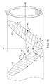
- FIG. 10A illustrates an exemplary perspective of a real-time georeferenced map generated during a sonde tracking process when steering along a specific track in 3-dimensional space, consistent with some embodiments of the present invention.
- FIG. 10B illustrates another exemplary perspective of a real-time georeferenced map generated during a sonde tracking process when steering along a specific track in 3-dimensional space, consistent with some embodiments of the present invention.
- FIG. 11A illustrates the calibration procedure for an exemplary sonde locating receiver when the sonde is placed at a known depth in the ground at an entry pit consistent with embodiments of the present invention.
- FIG. 11B illustrates the calibration procedure for an exemplary sonde locating receiver when the sonde is placed at an aboveground location consistent with some embodiments of the present invention.
- EM locators typically include a receiver and a transmitter, which may be a radiating underground conductor.
- a radiating underground conductor is a linear pipe or cable and the EM locator is configured to estimate the position of the underground pipe or cable.
- Sonde position estimation differs from the methods used for linear pipe or cable location, however, because the EM field emitted by the sonde is three dimensional and, accordingly, represented by magnetic dipole equations, which describe the decaying field strength of the EM field as the cube of the distance from the sonde. See e.g., Gard, “Magnetic Field Sensing in the Underground Construction Environment”, Sensors for Industry Conference, Houston, Tex., November 2002 (“Gard”).
- U.S. Pat. No. 7,009,399 provides for an EM locator that utilizes a 3-dimensional (3-D) receiver coil that reduces effects attributable to the “ghost” problem by calculating an EM field magnitude vector and corresponding EM field angles that unambiguously point to a sonde position.
- this “omnidirectional” detection method can lead to poor accuracy when the sonde is deep and the peak signal strength changes slowly over a broad area.
- this method also does not provide for independent estimates of the sonde orientation.
- Sonde orientation parameters e.g., roll, pitch, and yaw
- the locate point method utilizes two distinct points located at ground level where the EM field flux lines are vertical and converge to and from the poles of the sonde. These two distinct points are located on the axis of travel of the sonde transmitter behind and in front of the sonde's location. By determining the location of these two distinct points, the depth and position of the sonde may be determined by inference using the locate point method.
- Yaw angle i.e., “yaw” or “azimuth”
- pitch angle i.e., “pitch” or “inclination”
- the locate receiver uses the locally measured pitch to compute the depth and centerline position of the sonde.
- the locate point method requires knowledge of the position of the two distinct locate points as well as the locally measured transmitter pitch, the method belongs to a class of sonde locating solutions that requires a predefined geometrical relationship between the receiver and the transmitter, thus limiting its practical applicability. Further problems with the locate point method can occur when one or both of the locate points are physically inaccessible.
- locate point method in the context of underground directional boring applications include determining how to steer the drill head from a known location to a subsequent forward location.
- the locate point method typically utilizes known aboveground positions of the sonde locate receiver as a guide to steering the drill head to a specific forward location. As noted above, this steering requirement presents issues when certain aboveground positions are obstructed or otherwise inaccessible.
- Conventional solutions as provided in U.S. Pat. No. 6,250,402, do not allow for target positions other than the position represented by the distinct forward locate point. Even more contemporary solutions, such as those disclosed in U.S. Patent Publication No. 2007/0176603, still place constraints on the sonde movement as a relative function of the sonde's immediate position, pitch, and yaw, and are therefore sensitive to drift as offsets in these parameter estimates accumulate.
- Flux orientation locating methods operate by detecting a change in sign of the magnetic field at nulls in the detected field magnitudes via either deduction or direct wireline measurement of the received signal phase relative to the transmitter phase. Detecting this sign change helps to eliminate the slope ambiguities that occur as the receiver is traversed in the sonde field between the front and rear distinct locate points as well as in front of and behind these points to some degree.
- flux orientation locating methods also require locating the two distinct locate points and, like the aforementioned locate point method, are limited to a predefined geometrical relationship between the receiver and sonde transmitter.
- a complete description of the sonde orientation also requires roll information of the sonde about its cylindrical axis.
- Angular rotation of the drill head may be used to provide feedback to the operator for steering purposes, as with certain underground boring drill heads, a positive or negative roll of the sonde about its axis may be used to steer the sonde left or right.
- Conventional directional drilling systems often measure this roll information using a roll sensor integrated locally on the sonde capable of transmitting roll angle and pitch information to the surface using a telemetry process.
- Roll and pitch parameters measured locally at the sonde are problematic for a variety of reasons.
- harsh environmental conditions close to the drill head pose several issues in the context of local roll and pitch measurement.
- elevated temperatures and vibration present significant design challenges in achieving calibrated and stable local sensor measurements.
- Lower cost solid state roll and pitch sensors increase design complexities as temperate variations can directly affect their accuracy and reliability.
- locally measured roll and pitch data are often noisy due to high mechanical vibration forces experienced by the sonde/drill head and therefore require local filtering of the measured data prior to transmission to the surface. Such filtering can lead to latency or drift errors that bias estimates used for positioning in the locate point method.
- magnetic field distortion can bias any location method that relies on a fixed physical geometric model of the magnetic field shape to derive physical parameters. For example, eddy currents in the ground can distort the flux lines away from the ideal dipole shape, resulting in positioning errors for simple methods that rely on finding specific points in the field, as required by the locate point and flux orientation locate methods.
- Conventional systems are susceptible to such distortions and lack mechanisms for detecting when field distortion is present and when position estimates may have larger errors.
- mapping solutions of underground sondes conventionally provide georeferenced X-Y (e.g., latitude-longitude) positions and depths without any statement of accuracy. Because of potential field distortions, the accuracy of any particular estimate of sonde depth and centerline position can be biased when using physical models that are not adapted to local conditions.
- calibration of a conventional sonde locating system is typically based upon a one or two point measurement, either with the sonde exposed aboveground or buried at known depth (e.g., usually at the entry pit for the horizontal directional bore). Without increasing the calibration time, it is desirable to increase the number of calibration points, thereby reducing random bias, and to perform the calibration with the sonde fully within the ground so that effects related to ground conductivity and composition are taken into account.
- improvements over conventional methods are desirable in the measurement accuracy of sonde location and orientation.
- improvements derived from model-based precise location methods in the context of underground line locating may be utilized to improve the accuracy of sonde measurements.
- such methods are utilized in comparing a measured EM field at ground level in a minimization process to an EM field model for the transmitter being detected.
- Adaptation via nonlinear optimization may be used to tailor the state parameters in the model to the EM field measurements and the best set of state parameters for a given measurement set may be attributed with the estimated location of the transmitting sonde. Residual errors in the optimization process may be used to provide an indication of the confidence in the state parameter estimates.
- embodiments of the invention may utilize measurements of both magnitude and phase of the EM field emitted by the sonde transmitter. By measuring both the magnitude and phase, ambiguities in position deduction may be resolved such that the EM field can be measured at any location without knowledge of distinct locate points or the direction of the sonde axis, as is required by the locate point method discussed above. Accordingly, systems and methods consistent with embodiments of the invention do not require a predefined geometrical relationship between the locating receiver and the sonde transmitter. Moreover, knowledge of the precise location of locate points are also not required to generate a sonde position estimation.
- the locating receiver is configured to recover a phase reference that is synchronized with the EM signal transmitted by the sonde.
- the phase reference may be recovered through demodulation of the signal select reference.
- ⁇ verby both of which are assigned to Metrotech Corporation and are herein incorporated by reference in their entirety, are capable of providing an indication of the a detected EM signal's direction (e.g., phase) as well as its strength (e.g., magnitude).
- embodiments of the present invention may utilize signal select modulation, particularly in determining the direction of a measured EM signal, to in part resolve position ambiguities that are inherent in the previously described “ghost” problem.
- Signal select modulation may be used to deploy the transmitter and receivers independently without common clock synchronization, and still allow phase referenced measurements at the receiver.
- each individual measurement axis of the 3-D coil receiver may still exhibit some inherent measurement position ambiguity (e.g., ambiguity caused by a lack of knowledge of whether the receiver is in front of or behind the sonde) if only the magnitude of the signal is measured.
- the phase of the EM field measured at the ground surface emanating from an underground transmitting dipole e.g., a sonde
- the quadrature signals can be zero and the inphase component of the measured EM field can be negative.
- the quadrature signals may not be zero.
- the non-zero quadrature signal measurement may be an indication of signal interference from inductive and capacitive coupling of the sonde transmitter signal to other radiating sources.
- a measurable phase offset may be used as an indicator of EM field distortion and can be used to provide improved estimates of sonde's position and the expected error in that position.
- synchronized transmit and receive cycles using a tethered (e.g., wired) sonde or transmission of a pilot tone and pseudorandom training sequence in a similar method as digital subscriber line (DSL) modem systems may be utilized.
- DSL digital subscriber line
- Embodiments of the present invention may utilize various configurations of transmit and receive dipole antennas.
- a transmitter may include a single dipole antenna capable of emitting an EM field having an axis that is coincident with the longitude axis of the sonde.
- the sonde may transmit locally measured sonde pitch and roll information to the receiver over a telemetry link.
- the sonde locate receiver may include two 3-D coil clusters capable of measuring an EM field in three dimensions at two points in space (generally at ground level). Using the measured EM field, the locate receiver may estimate the position of the sonde and/or the yaw angle of the sonde from the reference (i.e., desired) path.
- the sonde transmitter may transmit EM fields in a single or in multiple dimensions.
- a sonde transmitter may transmit EM fields in two and/or three dimensions from the sonde.
- the sonde locate receiver may measure EM fields in a single or in multiple dimensions at one or more receiver 3-D EM coil cluster(s).
- Sonde position and orientation parameters may include a plurality of parameter states.
- three sonde position parameters may describe the position of the sonde in x, y, z space
- three sonde orientation parameters may describe the sonde's orientation, known as roll, pitch, and yaw.
- Sonde parameter states may be estimated using a model optimization method.
- one or more receiver 3-D EM coil clusters may be utilized to take redundant measurements which may be used to improve sonde position estimation confidence.
- geometric dimensions may be independently described by differing radiation models, and may conform to any EM field distribution including, for example, a dipole EM field distribution.
- the two axes orthogonal to the sonde radial axis may have EM flux lines that depend on the slot geometry of the drill string. Since a separate model can be defined for each dimension in the multi-dimensional transmitter, the optimization method may proceed in the same manner, with each dimension separately optimized against a best fitted model.
- FIG. 1 illustrates the aboveground use of a sonde locating receiver 100 consistent with some embodiments of the present invention to locate the position of an underground sonde 102 .
- the sonde illustrated in FIG. 1 includes a single transmitter capable of emitting an EM field 104 .
- a model-based precise locating method may be used to accurately locate and map sonde 102 (e.g., an underground dipole transmitter) in georeferenced (e.g., earth referenced) coordinates. Further, the method may be used to describe the sonde's orientation (e.g., roll, pitch, yaw) for directional drilling steering purposes.
- Sonde 102 may be integrated behind a drill head 106 at the end of a drill string 108 .
- sonde 102 may be located and tracked.
- the sonde locating receiver 100 illustrated in FIG. 1 is a cart-based receiver.
- Embodiments of a sonde location system consistent with the present invention may be integrated in hand-held devices, mounted on vehicles, or integrated in any device that can be moved relative to target sonde 102 .
- the forward direction of the sonde locate receiver 100 may be denoted as the z direction, in a translated plane coincident with z-axis 110 .
- the sonde 102 dipole axis may be the same z-axis.
- sonde 102 can have arbitrary orientations with respect to the cart receiver 100 (e.g., pitch denoted as ⁇ 114 , yaw denoted as ⁇ 116 , and roll denoted as ⁇ ).
- this “cart-based” coordinate frame may be translated into a georeferenced coordinate frame (e.g., an Earth-based coordinate frame) described by, for example, latitude, longitude, and elevation parameters.
- Angle ⁇ 124 shown in FIG. 1 , illustrates one parameter that may be utilized in the coordinate frame translation.
- parameters other than ⁇ 124 may be required to translate between coordinate frames. Translation between the cart-based coordinate frame and Earth-based coordinate frame may be achieved using techniques commonly implemented and well known in geographical surveying.
- cart-based locate receiver 100 may include cart frame 128 , display 130 , one or more wheels 132 , EM detector coils 122 , and locator receiver electronics 126 .
- locator receiver electronics 126 may include at least some of the components included illustrated in FIG. 2 and described in further detail below.
- EM detector coils 122 may be internally integrated within locator receiver electronics 126 .
- locator receiver electronics 126 may include systems for determining the location of cart-based location receiver including, for example, real-time kinematic (RTK) GPS, which may include GPS antenna 134 , odometers, gyroscopes, inertial sensors, accelerometers, digital level sensors, compasses, and/or precise survey grade location equipment (e.g., laser rangefinders, ultrasonic rangefinders, and/or on-board reflectors capable of integration with a laser theodolite total station system).
- the systems for determining the location of cart-based location receiver 100 may also provide confidence information related to the accuracy, of the estimated location of the cart 100 .
- the location of the cart 100 and any confidence information may be provided to a geographic information system (GIS) mapping platform, which in some embodiments, may be displayed to a user via display 130 .
- GIS geographic information system
- An underground target sonde 102 may be energized by an electric current from onboard transmitter electronics to emit EM field 104 .
- cart-based sonde locator 100 may include a pair of EM detector coils 122 mounted on each side of the cart frame 128 , and each EM detector coil 122 may include three EM coils configured to provide 3-dimensional electromagnetic field measurement information.
- 3-dimensional magnetometers may be used in lieu of and/or in addition to EM coils.
- EM detector coils 122 may be mounted on cart frame 128 within the wells of wheels 132 , providing the coils some protection as the cart traverses the locate path.
- cart-based sonde locator 100 may include any number of detector coils 122 positioned in other configurations.
- EM detector coils 122 can be performed as cart-based sonde locator 100 is traversed over target sonde 102 in a substantially parallel direction (i.e., substantially parallel with sonde 102 ), or in a substantially transverse direction (i.e., substantially transverse to the dipole axis of sonde 102 ).
- Other traversal paths may be utilized if the path of cart-based locate receiver 100 passes directly over sonde 102 and a sufficiently strong EM field 104 can be detected.
- Estimated position parameters of target sonde 102 may include depth, forward position, and horizontal offset of the receiver compared to the planned sonde track. This information may then be provided to a GIS mapping platform, which in some embodiments, may be displayed to a user via display 130 .
- the model EM field generated by a single hypothetical target sonde consistent with embodiments of the invention may have a nominal dipole field shape. In some embodiments, other model EM fields may be utilized depending on the mechanical configuration the transmitter coils in sonde 102 .
- the results of EM field 104 strength phase and amplitude measurements may be measured by EM detector coils 122 as well as location measurements for cart location systems may be provided to a model optimization module that takes into account that the complex EM field measurements were measured while traversing the target sonde in a substantially parallel or transverse direction.
- the sonde 102 detection process used by cart-based sonde locator 100 is similar to the previously discussed sonde detection methods that utilize a “walkover” technique, as described in the '383 patent, for electromagnetic field measurements and line (e.g., pipe or cable) location optimization modeling, the difference being that in the measuring sonde 102 location and orientation, measurements are taken as the EM detector coils 122 are moved along or across target sonde 102 and different field models are utilized. Accordingly, the geometrical relationship between sonde 102 and cart 100 necessary to properly locate sonde 102 may not be a strictly predefined condition.
- line e.g., pipe or cable
- an EM field from a candidate model may be compared with the measured EM field 104 and a model may be further optimized to one that best represents the measured EM field 104 which may then be used to provide an estimated position and orientation of sonde 102 .
- An error function can be formed using the mean square error of the final predicted field (e.g., the modeled field) after optimization, compared to the measured data. The results of this comparison may be used to determine confidence information that describes the accuracy of an estimated position of target sonde 102 and its estimated orientation parameters.
- the estimated location and orientation confidence information may be exported to the GIS system along with estimated target sonde 102 location and orientation parameters and displayed to a user via display 130 .
- cart 100 location confidence information provided by cart location determination systems may also be displayed to a user.
- georeferenced cart location confidence (e.g., mapping confidence) information may be combined with the estimated target sonde 102 location measurement confidence information to provide an overall confidence measurement for the estimated location of sonde 102 stated in terms of a chosen geographic coordinate system.
- the coordinate system utilized in locating sonde 102 may be “right handed”. That is, x is positive to the left of the direction of travel z, with y positive up from the origin, z positive forward from the original, and the sign of the angles defined by the “right hand rule”.
- the model EM field may be described as one measured at ground level from a 3-D (e.g., x, y, z) receiver coil cluster 122 wherein the orientation parameters of the hypothetical sonde (e.g., ⁇ , ⁇ , ⁇ ) are assumed to be zero.
- the model EM field, and the ideal measured EM field 104 absent any field distortion may be that of a multi-axis sonde transmitter 102 in any or all of 3 axes (e.g., x, y, z).
- An exemplary multi-axis sonde transmitter 102 consistent with embodiments of the present invention is illustrated in FIG. 3A .
- a multi-axis sonde transmitter 102 differs from conventional sonde transmitters which traditionally only have a single transmit, axis.
- Modeled and measured EM field strengths may be described in reference to both a transmitted signal orientation and a received signal orientation.
- field strength measurement/model h xy may describe a situation where the transmitted signal direction is in the x-axis plane and the received signal direction is in the y-axis plane.
- the field from constant current transmitters may be modeled according to the following:
- h xx A x ( 2 ⁇ x 2 - ( z 2 + y 2 ) ( x 2 + y 2 + z 2 ) 5 / 2 ( Equation ⁇ ⁇ 1 )
- h xz 3 ⁇ A x ⁇ xz ( x 2 + y 2 + z 2 ) 5 / 2 ( Equation ⁇ ⁇ 2 )
- h xy 3 ⁇ A x ⁇ yx ( x 2 + y 2 + z 2 ) 5 / 2 ( Equation ⁇ ⁇ 3 )
- h yx 3 ⁇ A y ⁇ xy ( x 2 + y 2 + z 2 ) 5 / 2 ( Equation ⁇ ⁇ ⁇ 4 )
- h yy A y ( 2 ⁇ y 2 - ( z 2 + y 2 ) ( x 2 + y 2 + z 2 ) 5 / 2 ( Equation ⁇ ⁇ 5 )
- the above referenced equations be used to represent both the magnitude and phase of the magnetic field strength of a selected transmitter axis (e.g., denoted by the first subscript x, y, or z) at a particular receiver coil axis (e.g., denoted by the second subscript x, y, or z).
- an AC excitation current applied to the transmitter coil of the sonde transmitter that may appear in the equations above. This current, however, may be lumped into transmitter specific constant A, as in some embodiments, the excitation current is kept constant by the sonde transmitter electronics.
- the constant A may be determined in a calibration step which is discussed in more detail below. Further, if the x and/or y sonde transmitters are not ideal dipole transmitters (e.g., due to the mechanical construction of the sonde), the above described model Equations 1-9 may vary but remain independent of other transmit directions.
- FIG. 2 illustrates a block diagram of sonde locating receiver electronics 126 consistent with some embodiments of the present invention.
- FIG. 2 illustrates embodiments of sonde locating receiver electronics 126 configured to measure a 3-D EM field 104 using two 3-D EM receiver coil clusters 122 (e.g., left and right 3-D EM coil clusters).
- sonde locate receiver 100 may be cart-based, particularly in high accuracy georeferenced coordinate locate applications.
- locate receiver 100 may include shaft encoder inputs 200 for one or more of the cart wheels 132 (e.g., left and right cart wheels) capable of precisely measuring cart travel distances over the ground.
- sonde locating receiver electronics 126 may include an analog input 202 (e.g., a 6-channel analog input) and an encoder input 204 (e.g., a 2-channel encoder input).
- Analog input 202 and encoder input 204 may provide digital-converted analog EM signals received from EM coils 122 and digital distance measurement information from encoders inputs 200 respectively to a digital signal processing (DSP) unit 206 .
- DSP digital signal processing
- DSP 206 may also be configured to receive cart orientation and location information from a 3-axis digital compass 208 , a 3-axis inertial measuring unit (IMU) 210 capable of measuring, for example, tilt and roll, which may be used to translate measurements taken with respect to the cart-based local coordinate frame to a georeferenced coordinate frame (e.g., an Earth-based coordinate frame). Further, DSP 206 may receive georeferenced cart location information from RTK-GPS receiver 212 . Alternatively or in addition, DSP 206 may receive geo-reference cart location information from other location systems including, for example, precise survey grade location equipment. DSP 206 may also be configured to implement the processing methods illustrated in FIGS. 5B and 5C . Further, in some embodiments, all processing in locate receiver 100 may be performed using DSP 206 .
- IMU 3-axis inertial measuring unit
- Sonde locating receiver electronics 126 may further include a field computer console and control unit 216 .
- Computer console and control 216 may be communicatively coupled with DSP 206 and/or RTK-GPS receiver 212 via USB or the like.
- computer console and control 216 may provide RTK-GPS receiver 212 with differential base corrections received from a wireless broadband interne system.
- computer console and control 216 may be coupled to display 130 and on-board drill rig telemetry 214 .
- computer console and control 216 may perform a model optimization process with the measured information to determine estimated sonde 102 location/orientation information and provide confidence information relating to the same.
- This information may then be transmitted to a drill rig telemetry unit 218 included in drill controller 136 by on-board drill rig telemetry 214 via wireless Bluetooth or the like, which may be used by a user of drill rig console and control 220 to steer sonde 102 to an arbitrary point along a predefined path independent of the measurement position of the sonde locating receiver.
- FIG. 3A illustrates a simplified exemplary 3-axis sonde transmitter 300 (e.g., sonde 102 in FIG. 1 ) with embedded electronics 302 and battery compartment 304 capable of emitting EM field 104 consistent with embodiments of the present invention.
- FIG. 3A illustrates an underground sonde transmitter 300 having up to three transmit axes 308 - 312 (e.g., x-axis, y-axis, z-axis).
- sonde 300 is capable of transmitting a 3-D dipole EM field.
- Battery compartment 304 may be configured to house batteries which power sonde electronics 302 .
- Sonde transmitter 300 may further include key 306 capable of locating the orientation of the sonde in the drill head carrier housing of an underground boring tool.
- FIG. 3B illustrates a block diagram of embedded electronics 302 included in an exemplary sonde transmitter 300 configured to drive one or more EM coils 122 at one or more modulated frequencies consistent with embodiments of the present invention.
- Sonde embedded electronics 302 includes a DSP unit 314 configured to generate a signal for each EM coil output channel and digital-to-analog converter (DAC) 316 configured to receive the digital signal provided by DSP 314 and generate corresponding analog signals for each of the one or more EM coil 122 channels.
- DSP 314 may provide DAC 316 with three digitally synthesized frequency signals.
- Each of the EM coil channels may include an output amplifier 322 and an analog filter 324 , which in some embodiments may be a low pass filter, and an EM transmitting coil 122 .
- DSP 314 may be configured to implement the previously described signal select algorithm on a separate carrier frequency for each active output axis (e.g., each of EM coil 122 channels).
- a programmable logic device may be used in lieu of or in addition to DSP 314 and DAC 316 .
- a direction digital synthesis block may be utilized.
- FIG. 4A illustrates another multi-axis sonde transmitter 400 with embedded electronics and battery consistent with some embodiments of the present invention.
- sonde transmitter illustrated in FIG. 4A is designed to operate inside a metal enclosure such as, for example, a sonde housing.
- sonde transmitter 400 may be configured to be an underground transmitter integrating a plurality of individual dipole transmitters, each of which may be configured to be orthogonal to the others.
- This design can operate inside a metal enclosure such as a sonde housing designed for horizontal direction drilling purposes and still radiate an AC-current induced magnetic field in desired direction(s). Only one transmitting axis is illustrated in FIG. 4A .
- At least two orthogonal transmit antennas are implemented to enable a ground based sonde locate receiver 100 to estimate all three sonde orientation angles (e.g., pitch, roll, and yaw). Particularly, if the sonde 400 is configured to transmit over two orthogonal antennas, neither one of the two transmitting antennas may need to be aligned with the cylindrical axis of the sonde 400 .
- At least one of the dipole transmitters may be aligned with the cylindrical axis of sonde 400 , which may allow for estimation of sonde 400 position and orientation during a drilling operation in which the sonde rotates. Roll angle may be estimated when sonde 400 is at rest using secondary dipole transmitters aligned at angles away from the cylindrical axis of the sonde.
- Embodiments of the sonde embedded electronics 302 illustrated in FIG. 3B may be utilized to induce a current in a secondary loop 404 illustrated in FIG. 4A , which in some embodiments may be constructed using a copper ring.
- embedded electronics 302 included in sonde 400 may couple an induced current from a primary coil to the secondary loop via torroid 406 (e.g., a ferrite torroid), thereby inducing a current in secondary loop 404 .
- sonde 400 may operate with minimal losses attributed to the sonde housing 402 by utilizing a secondary loop 404 that has a lower resistance than the sonde housing 402 .
- one or more slits 408 along the longitudinal axis of the sonde housing enclosure may be constructed to allow sufficient external emitted EM field strength by limiting the induced current in the pipe.
- FIG. 4B illustrates an exemplary 2-axis sonde transmitter 102 consistent with some embodiments of the present invention.
- 2-axis sonde transmitter 102 includes dipole axis 410 and 412 orientated orthogonally with respect to each other and both at 45° to the cylindrical axis of the sonde. It is noted that this dipole axis 410 - 412 orientation can still be applied to Equations 1-9, as orientation angles are calculated with respect to the sonde locate receiver 100 and the 45° pitch that results from this transmitter design can be removed numerically.
- dipole axes 410 - 412 may be driven utilizing signal select modulation, as described further below.
- dipole axis 410 may be driven, with signal select frequency F 1
- dipole axis 412 may be driven with frequency F 2
- both dipole axes 410 - 412 elements may driven together with frequency F 3 .
- all three frequencies can be active simultaneously, or to reduce power consumption of sonde 102
- frequency F 3 may only be active during active rotations of the drill rig.
- FIG. 4C illustrates a block diagram of an exemplary output stage included in embedded electronics of an exemplary sonde transmitter configured to drive a 2-axis sonde transmitter at three modulation frequencies consistent with some embodiments of the present invention.
- the output stage included in FIG. 4C may be utilized in embedded electronics 302 to drive two transmitter coils 420 L 1 and 422 L 2 .
- the output channels driving coils L 1 and L 2 may include a DAC 316 and an output amplifier stage 322 .
- DSP 314 may drive each output channels using signals which may be modulated according to one or more frequencies (e.g., f 1 , f 2 , and f 3 ).
- the current provided to coils L 1 and L 2 by output current transformers 420 and 422 respectively may vary accordingly to the one or more driving frequencies (e.g., f 1 , f 2 , and f 3 ).
- FIG. 4D illustrates a block diagram of an exemplary output stage included in embedded electronics of an exemplary sonde transmitter configured to utilize square waves to drive a 2-axis sonde transmitter consistent with some embodiments of the present invention.
- the embedded sonde output stage electronics illustrated in FIG. 4C may utilize square signal waves (e.g., F 1 , F 2 , and F 3 ) to generate EM fields emanating from dipole transmitter coils L 1 420 and L 2 422 (e.g., h 1 440 , h 2 442 , and h 3 444 illustrated in FIG. 4B ).
- the square signal waves may be generated by a programmable logic device (PLD) 446 included in embedded electronics 332 .
- this output stage design may minimize sonde 102 power consumption (e.g., increase sonde battery life).
- Output current transformer 420 which may be driven by drivers 428 and 430 , may mix square wave signals (e.g., F 1 and F 3 ) and induce current I 1 in transmitter coil L 1 .
- Output current transformer 422 which may be driven by drivers 430 and 432 , may mix square wave signals (e.g., F 2 and F 3 ) and induce current I 2 in transmitter coil L 2 .
- the induced output currents I 1 in coil L 1 and I 2 in coil L 2 may generate EM fields h 1 440 and h 2 442 , respectively, as illustrated in FIG. 4B .
- EM field h 3 444 may be generated, representing the vector sum of EM fields h 1 440 and h 2 442 , which in some embodiments may be aligned with the sonde longitude axis.
- FIG. 5A illustrates a spectrum plot 500 depicting the power spectra of three independent signal select modulated frequencies F 1 -F 3 configured to provide phase reference information generated by an exemplary three-axis sonde transmitter 102 .
- signal select modulation methods as described in the '414 patent and further described in the '383 patent, may be implemented using DSP 314 included in sonde embedded electronics 302 .
- FIG. 5A illustrates the use of three unique signal select modulation frequencies F 1 -F 3
- the choice of signal select modulation frequencies may be completely independent and can span the full underground locating bandwidth of approximately 10 Hz to 480 kHz. In certain applications with increased interference, lower frequencies spaced reasonably closely may be utilized. For applications requiring increased sensitivity and depth performance, higher frequencies may be utilized, such as, for example, 83 kHz.
- carrier frequency F 1 - 502 may represent the x-axis transmitter
- carrier frequency F 2 504 may represent the y-axis transmitter
- carrier frequency F 3 506 may represent the z-axis transmitter.
- signal select modulation may utilize very narrow bandwidths for transmission of phase reference information, such that the effective bandwidth used for locating information can be on the order of about 1-3 Hz per tone. Accordingly, the combined signal select based transmitter-receiver system may sustain little additional noise compared to conventional receivers which traditionally have roughly the same detection bandwidths.
- measurements of the resulting EM field 104 can be made by a compatible receiver on the ground for specific frequencies as predefined per axis.
- Signal select demodulation may occur at the receiver for each carrier frequency.
- signal select modulation frequencies may be selected so that the sidetones (e.g., 508 - 510 for carrier frequency F 1 502 ) do no overlap with sidetones or carriers utilized for other transmit axes.
- the EM field sensor at the receiver can include three orthogonal EM detector coils 122 . The signals received at EM detector coils 122 may be simultaneously processed to determine a measured EM field strength amplitude and phase information for one or more independent transmit directions.
- FIG. 5B illustrates a block diagram of an exemplary receiver channel 520 included in sonde locating receiver electronics 126 configured to receive EM field strength amplitude and phase measurements from an EM detector coil 122 and provide a corresponding digital signal, consistent with some embodiments of the present invention.
- a sonde locating receiver 100 may include a left and a right 3-D EM detector coil clusters 122 , each cluster including three orthogonally oriented EM detector coils.
- sonde locating receiver electronics 126 may receive six total measurement channels, one from each EM detector coil of the left and right 3-D EM detector coil clusters 122 , which may be provided to analog input 202 .
- FIG. 5B generally illustrates in more detailed an exemplary channel implementation included in analog input 202 for one input channel. Other input channels received by sonde locating receiver electronics 126 may be similar
- each input channel may include an analog-to-digital (ADC) converter 522 and a set of three nested phase-locked loop (PLL) blocks 524 - 528 .
- ADC analog-to-digital
- PLL phase-locked loop
- nested PLL blocks 524 - 528 may form the basis of a signal select dual nested PLL block for each of three signal select modulation frequencies F 1 502 , F 2 , 504 , and F 3 506 illustrated in FIG. 5A , emanating from a 3-axis dipole sonde transmitter 102 .
- Input channels may include a demodulator 530 for each of the three dual nested PLL blocks 524 - 528 .
- demodulator 530 may include a multiplier and lowpass filter capable of multiplying the input signal by the detected phase reference signal 532 .
- the demodulators 530 associated with the three dual nested PLL blocks 524 - 528 are capable of providing inphase and quadrature output signals computed for each transmit frequency (e.g., signal select modulation frequency), for each receiver coil cluster axis.
- 18 field strength values may be computed for a system that includes three transmit axes and three receive axes located on both the left and right side of a sonde locating receiver 100 .
- complex measurement value hL yx 534 may represent the measured and demodulated complex field strength from the EM receive coil oriented in the x-axis plane of the left 3-D EM coil cluster 122 of sonde locating receiver 100 emitted from the transmission coil oriented in the y-axis place of the 3-D sonde transmitter.
- the 18 field values hL xx , hL xy , hL xz , hL yx , etc. can represent both the magnitude and phase of the magnetic field strength of the selected transmitter axis at a particular receiver coil axis on the left side. Similar designations may be used for the field values received at the receiver coil axes in right side 3-D receiver coil cluster 122 (e.g. hR xy ).
- FIG. 5C illustrates a block diagram of another exemplary receiver design (e.g., a demodulator matrix) that may be included in sonde locating receiver electronics consistent with some embodiments of the present invention.
- demodulator matrix 542 illustrated in FIG. 5C may be implemented in conjunction with the receiver channel ADC signal 536 illustrated in FIG. 5B to allow for more accurate received sonde signal demodulation.
- the exemplary receiver channel 520 illustrated in FIG. 5B requires that the magnitude of the digital converted input signal 536 be sufficiently large in order to accurately measure an individual channel phase reference signal 532 . If the magnitude of input signal 536 is too low, the nested PLLs 524 - 528 may not phase lock and any measured phase reference 532 may be inaccurate.
- Exemplary demodulator matrix 542 mitigates the above-described limitations of single demodulator 530 .
- an alternative channel may be selected to serve as a phase reference signal.
- demodulator matrix 542 for a selected transmitter axis, such as the x-axis transmitter with signal select carrier frequency F 1 502 , digital converted input signals 536 , 538 , or 540 from one of the three receiver channels (e.g., one the receive channels associated with one of the EM coils included in EM coil cluster 122 ) may have sufficient magnitude such that the demodulated phase reference signal for that channel can serve as the PLL lock signal for all channels in the same coil cluster at the same carrier frequency (e.g., EM signals emitted from the same transmitter axis).
- a selected transmitter axis such as the x-axis transmitter with signal select carrier frequency F 1 502
- digital converted input signals 536 , 538 , or 540 from one of the three receiver channels may have sufficient magnitude such that the demodulated phase reference signal for that channel can serve as the PLL lock signal for all channels in the same coil cluster at the same carrier frequency (e.g., EM signals emitted from the same transmitter axis).
- the output of the set of three signals comprising output 552 or the like having the most stable phase reference may be determined.
- output signals may be denoted according to the respective receiver and/or transmitter axes associated with the channel.
- the last subscript in the signal hL xxy , et al may be utilized to denote the axis of the receiver used as the phase lock channel.
- a similar selection decision based on magnitude comparison may be performed for the other sets of three output signals 554 and/or 556 .
- the sonde locating receiver 100 measurement process may provide a set of 18 complex field strengths, each of which may be based on a stable phase reference.
- the signal processing embodied in the exemplary receiver designs illustrated in FIGS. 5B and 5C may, in some embodiments, be implemented using DSP 206 . Further, this signal processing may be utilize software-based implementations. In some embodiments, other implementations of the signal processing disclosed herein may be utilized (e.g., via programmable hardware architectures).
- FIG. 6 illustrates a process flow for a sonde locating receiver 100 consistent with some embodiments of the present invention.
- the measurement and demodulation process described above with respect to FIGS. 2 and 5 A- 5 C may be performed at step 602 .
- the amplitude and shape of EM field 104 and the modeled field used in optimization may be independent of signal frequency.
- the quadrature component of the signals hL xxy , et al can be discarded at step 604 , leaving the signed inphase component of the measured signals.
- the phase of the measured signals may be either 0° or ⁇ 180° and, therefore, can be used to indicate the EM signal direction.
- a simpler description of the system may be utilized that substitutes a set of 18 signed values.
- the measured signal select phase at the receiver may be utilized as a sensitive indicator of inductive and capacitive coupling effects, and the relative impact of such distortion on the measurement can be reflected in the magnitude of ⁇ , as is further described in the '383 patent.
- Equations 1-9 may be utilized to represent the ideal models of the expected EM field at the sonde locate receiver 100 as a function of the position of receiver 100 in the EM field 104 generated by sonde transmitter 102 . Utilizing these equations, a set of expected EM field models may be generated for one or more estimated sonde positions.
- sonde orientation parameters e.g., ⁇ , ⁇ , ⁇
- sonde orientation parameters may be presumed to converge to their actual values, allowing the measured EM field 104 to be rotated by the negated orientation angles and thus conform to Equations 1-9.
- a subscript L or R as well as a designator s to denote modeled values as opposed to measured values may be utilized. Accordingly, a hypothetical EM field generated by a transmitter coil oriented coincident with the y-axis plane at the sonde modeled at the location of an EM coil on the left EM coil cluster 122 oriented coincident with the x-axis plane may be denoted by hLs yx .
- a set of model parameter values and as well as measured parameter values including [x, y, z, ⁇ , ⁇ , ⁇ ] may be generated during the optimization process, represented by steps 608 - 612 , for each EM coil of a 3-D EM coil cluster 122 (e.g., a 3-D EM coil cluster for one side of a cart-based locate receiver having left and right 3-D EM coil clusters) respectively, with an assumption that sonde orientation parameters (e.g., ⁇ , ⁇ , ⁇ ) have zero values.
- sonde orientation parameters e.g., ⁇ , ⁇ , ⁇
- the optimization process described in steps 608 - 612 may proceed to determine a best fit expected EM field model to the measured EM field 104 , and the corresponding estimated sonde location associated with the selected best fit expected EM field model may be attributed with the location of the sonde 102 .
- a sonde locating receiver capable of computing 18 complex values per measurement point and a modeling process that can generate the expected 18 field values from a set of parameters a have been described.
- a nonlinear least squares optimization method may be utilized to determine a best fit expected EM field model to the measured EM field 104 , which in some embodiments may be the Levenberg-Marquardt optimization method.
- the above-described optimization method is similar to the optimization method described in the '383 patent in the context of a line-based “walkover locate” algorithm capable of utilizing a bleedover decoupling processing system to generate more accurate estimates of centerline, depth, and current of an underground utility line.
- the modeled EM field geometries represent cylindrical field strength distribution generated by a long continuous conductor.
- the walkover locate process described in the '383 patent may include repeated quadrature measurements of an EM field as a function of a transect distance (e.g., as the receiver moves transversely) above a target cable such as target line. Measured EM field data may be fit to an ideal EM model using a numerical optimization approach, and from the model the cable centerline, depth, and current estimates may be obtained.
- the optimization techniques described in the '383 patent may be adapted for a sonde-based walkover locate.
- the parameter set a may differ from those utilized in the '383 patent and the model EM field Equations 1-9 may be adapted to describe a dipole EM field distribution.
- signal processing modules included in receiver electronics 126 may be similar to those disclosed in the '383 patent in the context of a sonde locate receiver, including the “nested” dual digital PLLs 524 - 528 et al. utilized to demodulate amplitude and phase measurements of the measured EM field 104 illustrated in FIG. 5B .
- the determined best fit estimated sonde location parameters may be rotated and translated to a georeferenced coordinate frame from a cart based measurement coordinate frame at steps 614 - 618 .
- This coordinate rotation may be performed based on measured sonde orientation parameters associated with the measured EM field 104 as well as the estimated sonde orientation parameters associated with a sonde EM field orientation best fit model determined using a similar optimization process.
- Sonde location and orientation parameter estimates determined using the aforementioned optimization methods may be combined (step 616 ) and utilized to generate an updated sonde parameter vector (step 622 ) describing an estimated position and orientation of target sonde 102 .
- Differences between the best fit model EM field parameters and the measured EM field 104 parameters may be associated with an error value, which may be compared against a target error value at step 624 . If the error is within acceptable ranges, the process may proceed. However, if the error is outside acceptable ranges, the sonde position and orientation optimization processes (i.e., steps 608 - 618 ) may be repeated until the measured error is acceptable. Finally, the measurement error may be utilized at step 626 to provide confidence information related to measurement accuracy of one or more of estimated sonde position and orientation parameters [x, y, z, ⁇ , ⁇ , ⁇ ].
- An operator of sonde locate receiver 100 may perform a “walkover locate” over target sonde 102 at any angle with respect to the sonde's cylindrical axis for any distance.
- the above-described model fitting optimization process may provide estimated sonde position and orientation information regardless of whether the walkover path of the sonde locate receiver 100 is transverse (e.g., across the desired sonde path), along the sonde path, or parallel to any oblique angle in between.
- the geometrical description of the system may describe EM receiver coil 122 axes (x,y,z) as coincident with the sonde 102 (x,y,z) axes.
- deviations of the walkover path of the sonde locate receiver 100 from an orthogonal transect or a path having a direction substantially parallel to the target sonde cylindrical axis may be characterized as yaw angle (y) deviations.
- Step 1 Measurement ( 602 - 604 ): Collect the following sets of quadrature measurements (e.g., I, Q components at each measurement distance increment) relative to the demodulated phase reference (i.e., step 602 ):
- Step 2 Optimization ( 608 - 612 ): Using the signed in-phase component of the field strength, the non-linear optimization process may be performed to estimate a parameter vector [x, y, z, ⁇ , ⁇ , ⁇ ] three separate times for each measurement axis in sequence using:
- Step 3 Coordinate Rotation ( 614 - 618 ): Utilizing each of the parameter sets [x, y, z, ⁇ , ⁇ , ⁇ ] resulting from the optimization in steps a, b, and c of Step 2 :
- Step 4 Results ( 620 - 622 ): Two estimates of each orientation parameter ( ⁇ , ⁇ , ⁇ ) may be acquired from the following three optimization steps:
- Step 5 Confidence ( 626 ):
- the error in the final estimated target sonde 102 location and orientation parameter set may be estimated based on a comparison between the best fit model target sonde EM field and the measured EM field 104 data. From this comparison, the difference between the best fit model EM field and the measured EM field data may be used to generate confidence information related to the accuracy of the estimated EM field parameters. In some embodiments, this confidence information may be represented as a 1 ⁇ or 2 ⁇ confidence vector for the parameter set utilizing the methods described in U.S. Pat. No. 7,356,421 by Thorkell Gudmundsson, Johan D. ⁇ verby, Stevan Polak, James W. Waite, and Niklas Lindstrom (the '421 patent), which is assigned to Metrotech Corporation and herein incorporated by reference in its entirety.
- Similar steps may be utilized for both the sonde locate receiver's 100 left and right 3-D EM detector coil clusters 122 .
- a single 3-D coil cluster 122 may be utilized in the above-describe process to identify the position and orientation of a target sonde 102 .
- Such embodiments may utilize at least a two axis sonde EM field transmitter.
- two 3-D receiver coil clusters 102 may be utilized to determine sonde 102 position information and pitch and roll measurements may be obtained locally at sonde 102 through conventional methods.
- a unique parameter vector solution may not exist, even when two receiver coil clusters are used.
- sign changes that occur in the field may not be unambiguously detected. Accordingly, including phase measurements in the optimization process may allow for more accurate sonde position parameter estimation.
- a radiating target sonde 102 can induce an interference signal into other conductive media and objects. Eddy currents are one example of this undesirable coupling effect. Further, the target sonde 102 EM signal can in some circumstances re-radiate from any metallic object underground including utility lines that are in the vicinity of the radiating sonde 102 (e.g., signal bleedover). These signals, being in exactly the same frequency band as the transmitted sonde locating signal, can destructively cause interference at the point of receiver measurement on the ground.
- Embodiments of the invention may include a signal processing structure for refining models to account for the phase transfer function occurring between sonde transmitter 102 and locator 100 attributed to these interference effects, as are generally described in the '421 patent.
- Confidence bounds for both the target sonde 102 centerline and depth estimates can be similarly determined based on errors that result from the model optimization process due to interference and distortion (e.g., based on the differences between the best fit EM field model and the measured EM field 104 ).
- the methods described above help to ensure that estimated EM field parameters are more accurate over an entire walkthrough and help to minimize measurement error caused by field distortions.
- phase error term can be modeled as a function of location (e.g., reference to an x, y, z coordinate frame) and phase from each of the three demodulated EM receiver coils included in an 3-D EM receiver coil 122 , with the result that the model estimation of the parameter set ⁇ is less biased by bleedover coupling.
- FIGS. 7A-7C illustrates exemplary measured and modeled EM fields at the x-axis, y-axis, and z-axis receiver coils respectively of a 3-axis EM receiver coil cluster generated by a sonde having a transmitter oriented coincident to the x-axis coordinate plane.
- the measurement information presented in FIGS. 7A-7C illustrate an exemplary measurement set taken during a locate receiver 100 walkover across the path of the sonde.
- the measured EM field 104 is depicted as a solid line and the optimized best fit model EM field is depicted as a dashed line.
- Six other sets of measured and optimized EM field vectors representing measured y and z axes transmit outputs may be generated which exhibit similar behavior.
- nine measurement vectors may be used to estimate the optimized sonde location parameters.
- the following information can be obtained:
- the measurement accuracy requirement on sonde pitch may be more stringent than the measurement accuracy for sonde pitch due to certain utility installations (e.g., water, sewer, to maintain correct drainage or pressure), with close tolerances on the slope of the bored path.
- the target precision for the filtered pitch value may be on the order of 0.1°.
- a reduction in the 1 ⁇ error bound of the pitch estimate is possible by including more measurement points in the optimization. By lengthening the walkover distance and/or slowing the walkover speed so that more points are collected per unit time, larger position measurement diversity can be attained.
- in-place averaging (e.g., when the cart is stationary) may be utilized to reduce noise in the field measurements. That being said, the optimization process may be most accurate when field measurements are collected across a wider walkover transect within the measurable field over a high density of measurement points
- Sonde location and orientation estimation may typically be performed when the sonde is at rest (e.g., while another segment is added to the drill string 108 of an underground boring machine).
- the walkover process and, subsequent optimization pinpoint may be used to precisely estimate location of sonde 102 and its orientation.
- embodiments of the present invention allow for measurement of target sonde 102 position and orientation with no prerequisite knowledge of the geometrical relationship between the receiver 100 and sonde dipole transmitter 102 if the EM field 104 emanating from sonde 104 is detectable and if the signal select phase reference can still be demodulated from the measured field strengths.
- the position and orientation of sonde 102 at any point can be accurately estimated and placed in an Earth-based coordinate frame.
- Sonde tracking may be distinguished from sonde locating in that the precise sonde position may be previously estimated using the sonde location method while the sonde is stationary. As directional drilling resumes, target sonde 102 may move to a new position, ideally along a planned path. Utilizing sonde locating receiver 100 , steering information may be provided to a drill controller 136 operator so that the targeted sonde 102 position can be controlled to within acceptable tolerances.
- FIG. 8A illustrates the use of a sonde locating receiver 100 in steering sonde 102 consistent with some embodiments of the present invention. Particular, the FIG. 8A illustrates sonde steering from a two-dimensional perspective. In some situations, an operator may wish to steer target sonde 102 along a predefined drill path plan 820 . In some embodiments, a discrete representation of the place can be established on a 3-D map included in, for example, a GIS mapping platform, that may utilize any designated coordinate system. In some embodiments, the predefined drill path plan 820 may be downloaded to receiver 100 prior to commencing a drilling operation.
- a corrective drill path plan 822 may be required to bring the drill head (e.g., sonde 102 ) back into alignment with predefined drill path plan 820 .
- sonde 102 e.g., drill head
- Sonde receiver 100 may calculate a corrective drill path plan 822 to bring sonde 102 back into alignment with predefined drill path plan 820 at point B 826 .
- this calculated corrective drill path plan 822 may be conditioned on known limits on total curvature of the drill string and/or heading change limitations of the drill head.
- Corrective drill path 822 may be presented to the drill rig operator on console 220 as a corrective target path. While illustrated as a 2-D vector in FIG. 8A , corrective path 822 may be a 3-D vector calculated to provide a corrective path between two points in 3-D space.
- Equations 1-9 may be utilized to calculate expected magnetic field strengths to be observed by sonde receiver 100 at a known fixed position at each increment in sonde 102 position over corrective path 822 using the state estimates for the known sonde orientation angles to rotate the expected fields to align with the cart locator 100 local coordinate frame.
- 18 complex values (or 9 values if one 3-D receiver cluster 122 is utilized) generated by such calculations based on incremental sonde positions over corrective path 822 may be formed at each increment in position to generate a set of target models for the sonde's position as it moves between position A 824 to rejoin the desired drill path at 826 .
- FIG. 8B illustrates the use of a sonde locator for performing real-time georeferenced tracking of the sonde while in motion, consistent with some embodiments of the present invention.
- the process illustrated in FIG. 8B may employ an Extended Kalman tracking filter 806 to maintain georeferenced estimates of sonde 102 position as it moves along intended path 820 .
- an iterative Kalman process may be utilized to estimate incremental movement of the sonde from an established position.
- the Kalman method may be used to iteratively update estimates of physical parameters derived from sensor measurements by comparing those estimates to a reference parameter set derived from an a priori dynamic model.
- the Extended Kalman filter may be used for non-linear processes (e.g., processes from which sensor measurements are not linearly related to changes in the underlying model parameters). See e.g., Kalman Filtering, 2 nd edition, Grewal and Andrews, Wiley, 2001 (“Grewal”).
- corrective drill path 822 may be viewed as a nominal trajectory from which state vector changes can be viewed as approximately linear perturbations.
- this estimation process may be summarized in the four steps described below:
- Step 1 (steps 802 in FIG. 8B ):
- State vector X and process noise vector V may be defined as follows:
- X k [ x ⁇ ( k ) y ⁇ ( k ) z ⁇ ( k ) ⁇ ⁇ ( k ) ⁇ ⁇ ( k ) ]
- V k [ v x ⁇ ( k ) v y ⁇ ( k ) v z ⁇ ( k ) v ⁇ ⁇ ( k ) v ⁇ ⁇ ( k ) ] ( Equation ⁇ ⁇ 10 )
- x(k), y(k), z(k) denote the known receiver position in the sonde 102 coordinate system
- ⁇ (k), ⁇ (k) denote the known sonde pitch and yaw
- k may denote an incrementing integer.
- sonde roll angle ⁇ (k) may in some embodiments be ignored.
- an operator of the drill controller 136 may impart force inputs (e.g., noise) to the drilling system that create sonde 102 position and orientation changes.
- sonde position and orientation changes attributable to noise at each time interval may lumped into noise terms, denoted as ⁇ x (k), ⁇ y (k), ⁇ z (k), ⁇ ⁇ (k), ⁇ ⁇ (k), with a corresponding correlation matrix Q based, for example, on the physical constraints of the drill string flex and heading change limitations.
- Matrix Q describes the correlations between all pairs of data sets of V k .
- a measurement equation matrix may be H(x(k), y(k), z(k), ⁇ (k), ⁇ (k)) may be defined using the previously described walkover optimization (steps 810 and 804 ).
- a coordinate system transformation between the sonde coordinate system and the receiver coordinate system accounting for orientation of the sonde 102 , with the exception of roll, may be determined by a direction cosine matrix denoted as T( ⁇ (k), ⁇ (k)).
- T direction cosine matrix
- a theoretical measurement from a 3-D coil cluster 122 at the receiver position [x(k), y(k), z(k)] due to a single z-axis sonde 102 transmitter can be modeled according to Equation 12:
- Equation ⁇ ⁇ 14 W is a measurement noise vector with a correlation matrix R which describes the correlations between all pairs of data sets of W. Further, the notation provided in Equation 14 is defined such that h x 1 describes the x-axis coil measurement of the left receiver on the cart.
- Step 3 A matrix of linear approximation equations C k for a change in the field measurements H about a current trajectory may be constructed according to Equation 15.
- C k ⁇ H ⁇ ( k , X ) ⁇ X ⁇
- X X ⁇ ⁇ ( k / Y k - 1 ) ( Equation ⁇ ⁇ 15 ) wherein the ijth entry of C k is equal to the partial derivative of the ith component of C k with respect to the jth component of X.
- Equation 16 Equation 16 wherein initial conditions, ⁇ circumflex over (X) ⁇ 0/0 , denote the previous position and sonde orientation estimation when sonde is at rest at point a known point (e.g., A 824 ), and P 0/0 denotes the a correlation matrix resulting from the optimization confidence estimation.
- the Extended Kalman tracking filter may provides update of the state vector at each update interval in real-time as the sonde is moving from a known point to a subsequent rest position. In some embodiments, this update interval may be at a rate of five updates per second. In further, in some embodiments, for every estimation step, an updated georeferenced position may be computed by rotation and translation of the cart frame into an earth-based frame, so that the placement of the sonde can be constantly reviewed in the selected local spatial coordinates at an operator's discretion (steps 812 , 814 , 816 ).
- FIG. 9 is an exemplary sonde tracking display used in conjunction with a cart based sonde locating system 100 , when the sonde 102 is actively moving down a drill path, consistent with some embodiments of the present invention.
- the display illustrated in FIG. 9 is from an underground perspective behind the sonde looking forward.
- the sonde 102 may be represented in the figure by a dark circle 900 located in the middle of the central graph.
- the current 1 ⁇ confidence interval on the sonde vertical and horizontal position may be represented by the shaded rectangle 902 around the sonde 900 .
- each grid division may be fixed at 50 cm vertically and 20 cm horizontally. Any appropriate grid spacing, however, may be utilized.
- the display illustrated in FIG. 9 is used to monitor the sonde 102 position relative to the locator cart 100 platform, and to view current estimates of the sonde position and orientation (x, y, z, ⁇ , ⁇ , ⁇ ).
- the wheels 132 of the locate receiver cart 100 may be represented schematically by icons 904 , which by color and “ ⁇ ” labels may indicate varying degrees of field distortion detected when the signal select phase angle increases away from a nominal 0°. With the wheels 132 as a reference, the relative placement of the underground sonde 900 can be easily referenced by simple inspection.
- a further clarifying display element 924 may be used to show the off-axis distance (e.g., the distance away from the center of the cart) in, for example, centimeters, and the direction to steer the cart such that the sonde is directly underground.
- Depth indication 908 may denote the belowground distance of the sonde.
- Yaw angle indication 906 may describe the deviation of the path of the sonde in a level plane from the locator cart 100 direction path.
- Course indication 916 may represent the heading of the cart with respect to true North.
- Speed indication 914 may indicate the relative speed of the sonde 102 compared to the locator cart 100 (which also may be stationary or moving).
- the GPS fix quality of the locator cart may be indicated by indicator 918 .
- “AdVanceRTK” indicates a high quality RTK-GPS positioning solution is available, commonly with less than a 2 cm error in map position ( 1 ⁇ confidence).
- Indication 920 may show the number of GPS satellite vehicles (SV) in view, as well as the number used in determining the geo-reference position of the cart locate receiver 100 .
- bar graph 922 may provide a quick summary of the cart based sonde locating system 100 accuracy in terms of locate error (LOC), GPS subsystem error, as well as overall positioning error (MAP).
- LOC locate error
- MAP overall positioning error
- Overall map error is typically less than or equal to the GPS error, since the cart may implement embedded dead-reckoning algorithms that utilize a 3-D digital compass, a 3-D inertial measurement unit, and odometers to maintain map precision in areas where the GPS signal is lost.
- dead reckoning methods are described in U.S. Pat. No. 7,120,564, by Gordon Pacey (the '564 patent), U.S. Pat. No. 7,113,124, by James W. Waite, and U.S. Divisional patent application Ser. No. 11/193,100, by James W. Waite and Ruwan Welaratna, all of which are assigned to Metrotech Corporation and herein incorporated by reference in their entireties.
- Pitch indication 910 and roll indication 912 may represent estimates of the target sonde 100 orientation.
- the estimated roll value (if measured using optimization and an x-axis or y-axis transmitter) may only be accurate when the sonde is stopped and the drill rig stationary. While locator cart 100 platform tilt and roll values are not included in the display illustrated in FIG. 9 , these values may be measured and accounted for in translating the cart-based sonde 102 location and orientation measurements to a Earth-based coordinate frame.
- FIGS. 10A and 10B illustrate exemplary perspectives of a real-time georeferenced maps generated during a sonde tracking process when steering along a specific track in 3-D space, consistent with some embodiments of the present invention.
- FIG. 10A illustrates a bird's eye view of both the locator cart 100 track and the underground sonde 102 as both the target sonde 102 and the locator cart 100 progressively move from one end of a drilling operation (starting at the west side) to a terminus 80 m to the east.
- the locator cart 100 may be moved several times between places of rest 1000 .
- Linear position scale 1002 included in FIG. 10A represents 1 meter in both the north (e.g., vertical) axis and 1 meter in the east (e.g., horizontal) axis, and may be used to describe the side-to-side deviation of the cart from the sonde track.
- the off-axis horizontal deviation of the exemplary cart 100 shown in the figure to the observed sonde position is approximately one meter across an 80 meter drill plan.
- FIG. 10A may also include an indication showing the deviation of the observed sonde track from a predefined drill plan (e.g., 822 ).
- the Kalman tracking filter may provide live updates on the map of the sonde position (x,y,z) and a partial orientation ( ⁇ , ⁇ ).
- walkover data may be collected in accordance with the methods described above in the context of sonde location.
- the cart also rests 1000 and optimization and parameter estimation processes may be performed.
- the Kalman tracking filter states may be updated with both updated parameter estimates and their standard deviations.
- an updated optimal drill path 822 may be calculated and displayed to an operator of console 220 .
- the drill rig operator may also be presented with new position, roll, and pitch estimations.
- Local data-logging of estimated position and orientation results generated by the sonde locating receiver 100 may be utilized to facilitate GIS system export of the entire 3-D drill track after the drill job is completed.
- the above-described “leapfrog process” of sonde locating (e.g., using walkover optimization) and sonde tracking (e.g., using Kalman filtering) may occur successively until the sonde 102 reaches an intended destination at the terminus of the drill path.
- a perspective view of the drill track may be available as a display choice, as shown in FIGS. 10A and 10B .
- the two higher modulation frequencies may be utilized to carry low bandwidth temperature and battery voltage information.
- Analog levels for both temperature and voltage may be measured locally on the sonde 102 . Between designated lower and upper limits, the measured value may be mapped to a frequency in the range 562 (e.g., voltage) and 564 (e.g., temperature). Utilizing these carrier frequencies may change the signal select carrier frequency value and thus may be communicated to the locate receiver 100 .
- the receiver 100 may utilize a constant estimate of carrier frequency through the numerically controlled oscillator that exists for each PLL ( 524 - 528 ), and thus can perform reverse mapping of frequency to temperature or voltage, as is required.
- a typical range for the carrier intervals 562 and 564 is ⁇ 0.25% of the carrier frequency.
- the first frequency F 1 502 of the x-axis transmitter may be kept fixed and be used as a reference frequency. All battery and temperature measurements may be referenced to this frequency, thereby ensuring that sonde 102 frequency drifts due to environmental changes can be tracked and removed from the equations for the measured voltage and temperature. In this manner, the computation of the temperature and battery status may be automatically compensated for any frequency drifts in the sonde transmitter 102 .
- the higher two frequencies F 2 504 and F 3 506 for the y-axis and z-axis transmitters can be separated from F 1 502 by a progressive fixed increments 558 ⁇ f 2 and 560 ⁇ f 3 . Denoting f C as the system clock of the sonde and f TA as the combined temperature and aging crystal drift, frequencies F 1 , 502 , F 2 504 , and F 3 506 may be expressed as follows:
- Embodiments of the invention allow information to be wirelessly sent from the sonde locating receiver 100 to the drill rig controller 136 (e.g., as illustrated FIGS. 1 and 2 ). Standard local computer protocols like Bluetooth, WiFi, and the like may be implemented to achieve this information transfer. Further, a remote display included on the drill rig controller 136 can provide a simple map of sonde position and orientation compared to the an optimal planned track (e.g., 822 ), which in some embodiments may be similar to the maps included in FIGS. 10A and 10B .
- FIG. 11A illustrates the calibration procedure for an exemplary sonde locating receiver 100 when the sonde 102 is placed at a known depth 1106 in the ground at an entry pit 1100 consistent with embodiments of the present invention.
- In-situ (e.g., on-site or in ground) calibration of the sonde locating system 100 may be accomplished with the sonde transmitter placed in the drill string 108 at a position behind the drill head 106 .
- a transverse (e.g., 90° to the direction of the drill string) walkover measurement (denoted by direction 1102 ) of the known depth d 1106 may be performed across the midsection of the buried sonde at the edge of the pit 1100 .
- Field measurements 1104 may be collected in accordance with the methods described herein.
- the depth 1106 may be physically measured with a tape measure or the like, and the physically measured depth value d 1106 may be entered into a calibration dialog at the user console/display 130 .
- the sonde locating receiver 100 may simultaneously measure the transverse position as well as recording field strength from all 3 axes, using one or both 3-D EM coil modules 122 .
- the z-axis intercepts of the walkover for the EM coil modules 122 on both left and right sides may be determined to within a few centimeters accuracy. With the sonde 102 correctly positioned horizontally, the sonde orientation angles may also be approximately zero.
- the calibration parameter vector b may be adapted until the minimum mean squared error is sufficiently low.
- the calibration of locate receiver 100 may terminate and the constant A may be stored for use by locate receiver 100 in new locate runs for which the depth 1106 is an unknown.
- the limits on the possible values of the orientation can be constrained to small angles (e.g., ⁇ , ⁇ , ⁇ may be small) such as, for example, the calibration configuration illustrated in FIG. 11A .
- the constant A may only be utilized on a particular site if current is maintained at a constant value through each sonde transmitter 102 coil for both the calibration and all subsequent locating operations, regardless of battery level. Accordingly, power supply circuit 320 illustrated in FIG. 3B may be adapted to maintain constant transmitter 102 coil current levels.
- FIG. 11B illustrates the calibration procedure for an exemplary sonde locating receiver when the sonde is placed at an aboveground location consistent with some embodiments of the present invention.
- the calibration procedure illustrated in FIG. 11B may be utilized when it is not possible to perform an in-situ calibration with the sonde transmitter 102 in the ground. Such situations may arise, for example, if an entry pit 1100 does not exist as is the case when the drill track begins on a slope.
- cart-based sonde locating receiver 100 may be placed alongside drill string 108 at separation distance x 1112 from sonde transmitter 102 .
- the depth of the sonde referenced to the receiver coil cluster center may be measured as d 1110 .
- d 1110 may represent the height differential between the center of 3-D EM coil clusters 122 and the center of sonde transmitter 102 .
- the value d may be the only absolutely known quantity during calibration, since the user may push the cart 100 as a somewhat oblique angle to the sonde 102 and thus the distance x 1112 may not be a constant.
- the oblique angle between the cart 100 direction 1108 and the longitude axis of the sonde transmitter may be denoted as yaw ⁇ , which can be estimated along with the factor A using the aforementioned calibration process.
- Cart 100 may be used to perform a walkover locate alongside drill string 108 starting at some arbitrary distance behind sonde 102 and finishing at a distance ahead of the sonde 102 .
- the estimated location and depth of target sonde 102 may be determined using the above described techniques within a cart-based coordinate frame (e.g., rather than a sonde-based coordinate system utilized in Equations 1-9).
- a cart-based coordinate frame e.g., rather than a sonde-based coordinate system utilized in Equations 1-9.
- locator receiver electronics 116 e.g., gyroscopes, accelerometers, internal sensors, and/or digital level sensors
- the position of the cart 100 within the cart-based coordinate frame may be determined.
- systems for determining the location of cart-based location receiver 100 included within locator receiver electronics 116 may be used to determine the position of the cart 100 within an earth coordinate frame (e.g., a georeferenced coordinate frame).
- an earth coordinate frame e.g., a georeferenced coordinate frame.
- the estimated location and depth of target sonde 102 is determined in reference to the cart-based coordinate frame and may be translated into an estimated location and depth of target sonde 102 within an earth coordinate frame.
- variations in the position of the cart 100 may be accounted for in determining the estimated parameters of target sonde 102 within the earth based coordinate frame, which may then be exported to a GIS mapping platform and displayed to a user via display 130 .
- a drill plan (e.g., a planned drilling path) may be defined in an earth-coordinate frame, representing the desired path of the drill head in three dimensions.
- the location of the target sonde 102 may be translated into the same earth-coordinate frame, and compared to the drill plan which may be pre-loaded into an online map like similar to that displayed in FIGS. 10A and 10B .
- the actual path e.g., the measured path
Abstract
Description
{right arrow over (a)}=[x,y,z,θ,φ,γ]
wherein,
-
- x 118,
y 120, andz 110 have origins located at the center ofsonde 102; - z is the forward position of the locate
receiver 100 with respect to thesonde 102, in the level direction of the desired path of travel. The z-axis 110 may generally be in the same plane as the local definition of mean sea level (MSL), but can differ by the tilt and roll of the cart with respect to the gravitational vector. The z-axis may be coincident with the dipole axis ofsonde 102 when the sonde yaw or pitch are both zero; - x is the off-axis (e.g., side) position of the receiver relative to the z-axis;
- y is the vertical position of the receiver with respect to
sonde 102, and may be substantially aligned with a radial vector from the center of the Earth (e.g., the gravitational vector). Because the tilt and roll of the cart can vary with respect to the gravitational vector, a coordinate translation may be performed to relate y to the depth ofsonde 102; - θ 116 is the pitch angle of
sonde 102 about the x-axis; - φ is the roll angle of the
sonde 102 about the dipole axis; and -
γ 114 is the yaw angle ofsonde 102 about the-y axis, referenced to the coordinate plane z.
- x 118,
wherein Ax, Ay, Az are transmitter specific parameters.
-
- a. [hxxhxyhxz]—3-D field measurements at the sonde locate
receiver 100 on the ground from the x-direction transmit coil ofsonde 102; - b. [hyx hyy hyz]—3-D field measurements at the sonde locate
receiver 100 on the ground from the y-direction transmit coil ofsonde 102; - c. [hzx hzy hzz]—3-D field measurements at the sonde locate
receiver 100 on the ground from the z-direction transmit coil ofsonde 102; and - d. Discard the quadrature components of the field values (step 604). The resulting in-phase component may be described as a signed version of the measured
EM field 104 strength.
- a. [hxxhxyhxz]—3-D field measurements at the sonde locate
-
- a. Re[hxx hxy hxz] demodulated from frequency F1;
- b. Re[hyx, hyy hyz] demodulated from frequency F2; and
- c. Re[hzx hzy hzz] demodulated from frequency F3.
-
- a. Compute the model-based estimated field (e.g., compute the model-based field from each of the three parameter sets), calculating field values hsxx, hsxy, hsxz, hsyx, hsyy, hsyz, hszx, hszy, and hszz;
- b. Rotate the measurement field values Re[hxx hxy hxz], Re[hyx hyy hyz], and Re[hzx hzy hzz] by negated versions of optimized pitch, roll, and yaw angles (θ, φ, γ);
- c. Form an error matrix by subtracting the rotated and measured field values from the model values (e.g., for the entire walkover);
- d.
Repeat Step 2 andStep 3 until the error converges to less than a defined threshold; - e. For each iteration, compare the measured field to the adapted model field equation set which assume no pitch, roll, or yaw; and
- f. Over the course of the orientation optimization, pitch, roll, and yaw angles (θ, φ, γ) converge to their expect values as the error in the computer field is minimized compared to the measured field.
-
- a. roll φ and yaw γ from Step 2 a;
- b. pitch θ and roll φ from Step 2 b; and
- c. pitch θ and yaw γ from Step 2 c.
The two estimates of orientation angles (θ, φ, γ) may be averaged together. The position of the sonde (e.g., in reference to the x, y, z coordinate frame) may be averaged from the three step optimization results, the inputs of which may depend on the predominant direction of the walkover (e.g., transverse or alongside the sonde) and, in some embodiments, utilize only two of the three transmitted EM field axes.
-
- The sonde is at depth 76 cm;
- The walkover transect crossed the z-axis at 45 cm at 1.09 meters into the walkover;
- The 1σ position error (depth, centerline, and offset) are 1 cm each; and
- The estimated pitch, roll, and yaw angles of the sonde are 1.0°, 3.6°, and 7.2° respectively, each with a 1σ error of less than 0.3°.
wherein, x(k), y(k), z(k) denote the known receiver position in the
X k+1 =X k +V k (Equation 11)
Y k =H(k,X k)+W (Equation 13)
wherein
and W is a measurement noise vector with a correlation matrix R which describes the correlations between all pairs of data sets of W. Further, the notation provided in Equation 14 is defined such that hx 1 describes the x-axis coil measurement of the left receiver on the cart.
wherein the ijth entry of Ck is equal to the partial derivative of the ith component of Ck with respect to the jth component of X.
G k =P k/k−1 ·C k T ·[C k ·P k/k−1 ·C k T +R] −1
αk =Y k −H({circumflex over (X)} k/k−1)
{circumflex over (X)} k/k ={circumflex over (X)} k/k−1 +G k·αk
{circumflex over (X)} k+1/k ={circumflex over (X)} k/k
P k/k=(I−G k ·C k)·P k/k−1
P k+1/k =P k/k +Q
k=1, 2, 3, . . . (Equation 16)
wherein initial conditions, {circumflex over (X)}0/0, denote the previous position and sonde orientation estimation when sonde is at rest at point a known point (e.g., A 824), and P0/0 denotes the a correlation matrix resulting from the optimization confidence estimation.
wherein R is the division factor to bring the system clock to the nominal signal select center frequency, V is the battery voltage, T is the sonde temperature, and k1, k2 are physical scale factors to scale the values to a
Remote Monitoring of the Sonde Receiver at the Drill Rig Controller
Claims (15)
Priority Applications (1)
| Application Number | Priority Date | Filing Date | Title |
|---|---|---|---|
| US13/477,909 US9158024B2 (en) | 2008-12-05 | 2012-05-22 | System for determining a precise location and orientation of a concealed dipole transmitter |
Applications Claiming Priority (2)
| Application Number | Priority Date | Filing Date | Title |
|---|---|---|---|
| US12/315,696 US8188745B2 (en) | 2008-12-05 | 2008-12-05 | Precise location and orientation of a concealed dipole transmitter |
| US13/477,909 US9158024B2 (en) | 2008-12-05 | 2012-05-22 | System for determining a precise location and orientation of a concealed dipole transmitter |
Related Parent Applications (1)
| Application Number | Title | Priority Date | Filing Date |
|---|---|---|---|
| US12/315,696 Division US8188745B2 (en) | 2008-12-05 | 2008-12-05 | Precise location and orientation of a concealed dipole transmitter |
Publications (2)
| Publication Number | Publication Date |
|---|---|
| US20120232800A1 US20120232800A1 (en) | 2012-09-13 |
| US9158024B2 true US9158024B2 (en) | 2015-10-13 |
Family
ID=42230359
Family Applications (2)
| Application Number | Title | Priority Date | Filing Date |
|---|---|---|---|
| US12/315,696 Active 2030-10-25 US8188745B2 (en) | 2008-12-05 | 2008-12-05 | Precise location and orientation of a concealed dipole transmitter |
| US13/477,909 Active 2030-08-31 US9158024B2 (en) | 2008-12-05 | 2012-05-22 | System for determining a precise location and orientation of a concealed dipole transmitter |
Family Applications Before (1)
| Application Number | Title | Priority Date | Filing Date |
|---|---|---|---|
| US12/315,696 Active 2030-10-25 US8188745B2 (en) | 2008-12-05 | 2008-12-05 | Precise location and orientation of a concealed dipole transmitter |
Country Status (2)
| Country | Link |
|---|---|
| US (2) | US8188745B2 (en) |
| WO (1) | WO2010065675A1 (en) |
Cited By (5)
| Publication number | Priority date | Publication date | Assignee | Title |
|---|---|---|---|---|
| US20140012505A1 (en) * | 2011-03-31 | 2014-01-09 | Laurentian University Of Sudbury | Multi-component electromagnetic prospecting apparatus and method of use thereof |
| US20150077120A1 (en) * | 2013-07-15 | 2015-03-19 | SeeScan, Inc. | Utility locator transmitter devices, systems, and methods with dockable apparatus |
| CN105467455A (en) * | 2015-11-20 | 2016-04-06 | 北京瑞芯谷科技有限公司 | Method for searching underground facility by using underground electronic identifier precisely |
| US10222465B2 (en) | 2015-12-29 | 2019-03-05 | Geophysical Survey Systems, Inc. | Magnetic field detector and ground-penetrating radar device with merged display |
| US20210215000A1 (en) * | 2020-01-14 | 2021-07-15 | Underground Magnetics, Inc. | Accomodating pitch instability in horizontal directional drilling |
Families Citing this family (53)
| Publication number | Priority date | Publication date | Assignee | Title |
|---|---|---|---|---|
| CN101598016B (en) * | 2009-04-16 | 2013-03-27 | 宁波金地电子有限公司 | Depth multi-point correction method for horizontal positioning drill guide instrument |
| US8729901B2 (en) | 2009-07-06 | 2014-05-20 | Merlin Technology, Inc. | Measurement device and associated method for use in frequency selection for inground transmission |
| EP2513666B1 (en) * | 2009-12-18 | 2015-02-18 | L-3 Communications Cyterra Corporation | Moving entity detection |
| US9151822B2 (en) * | 2009-12-31 | 2015-10-06 | Optimal Ranging, Inc. | Precise positioning using a distributed sensor network |
| EP2519839A4 (en) * | 2009-12-31 | 2018-03-28 | Optimal Ranging, Inc. | Precise positioning using a distributed sensor network |
| US8816689B2 (en) * | 2011-05-17 | 2014-08-26 | Saudi Arabian Oil Company | Apparatus and method for multi-component wellbore electric field Measurements using capacitive sensors |
| EP2723983B1 (en) * | 2011-06-21 | 2018-04-11 | Vermeer Manufacturing Company | Horizontal directional drilling system including sonde position detection using global positioning systems |
| FR2977968B1 (en) * | 2011-07-12 | 2014-09-19 | Soletanche Freyssinet | METHOD FOR REPRESENTING THE POSSIBLE MOVEMENTS OF A STRUCTURE FOR AN ORDINARY TYPE APPARATUS |
| US20130054075A1 (en) * | 2011-08-22 | 2013-02-28 | Deere And Company | Location Control System for Feature Placement |
| US9172225B2 (en) * | 2011-09-22 | 2015-10-27 | Labor Saving Systems, Ltd. | Induction-based reference point locator |
| US11193767B1 (en) * | 2012-02-15 | 2021-12-07 | Seescan, Inc | Smart paint stick devices and methods |
| US10809408B1 (en) * | 2012-03-06 | 2020-10-20 | SeeScan, Inc. | Dual sensed locating systems and methods |
| US9411067B2 (en) * | 2012-03-26 | 2016-08-09 | SeeScan, Inc. | Ground-tracking systems and apparatus |
| EP2831642A2 (en) * | 2012-03-26 | 2015-02-04 | Mark Olsson | Ground tracking systems and apparatus |
| US9671233B2 (en) * | 2012-11-08 | 2017-06-06 | Uber Technologies, Inc. | Dynamically providing position information of a transit object to a computing device |
| EP2752680B1 (en) * | 2013-01-04 | 2016-05-11 | Ortovox Sportartikel GmbH | Search system and method for searching for a buried person |
| US9500464B2 (en) | 2013-03-12 | 2016-11-22 | Adidas Ag | Methods of determining performance information for individuals and sports objects |
| US20140278838A1 (en) | 2013-03-14 | 2014-09-18 | Uber Technologies, Inc. | Determining an amount for a toll based on location data points provided by a computing device |
| BR112015032628A2 (en) * | 2013-07-29 | 2017-07-25 | Landmark Graphics Corp | methods for displaying data for a preferred well on a mobile device and for reconfiguring a system on a computer, and non-transient program-carrying device |
| JP6153493B2 (en) * | 2014-04-25 | 2017-06-28 | ヤマハ発動機株式会社 | Roll angle estimation device and transport equipment |
| US20190004122A1 (en) * | 2014-04-25 | 2019-01-03 | Purdue Research Foundation | Wireless position sensing using magnetic field of single transmitter |
| US10101408B2 (en) * | 2014-04-25 | 2018-10-16 | Purdue Research Foundation | Wireless position sensing using magnetic field of single transmitter |
| US10424036B2 (en) | 2014-06-02 | 2019-09-24 | Uber Technologies, Inc. | Maintaining data for use with a transport service during connectivity loss between systems |
| US9928613B2 (en) * | 2014-07-01 | 2018-03-27 | SeeScan, Inc. | Ground tracking apparatus, systems, and methods |
| JP7136558B2 (en) | 2015-03-05 | 2022-09-13 | マジック リープ, インコーポレイテッド | Systems and methods for augmented reality |
| US10838207B2 (en) * | 2015-03-05 | 2020-11-17 | Magic Leap, Inc. | Systems and methods for augmented reality |
| US10180734B2 (en) | 2015-03-05 | 2019-01-15 | Magic Leap, Inc. | Systems and methods for augmented reality |
| AR104370A1 (en) * | 2015-04-13 | 2017-07-19 | Leica Geosystems Pty Ltd | MAGNETOMETRIC COMPENSATION |
| US10527412B2 (en) * | 2015-10-06 | 2020-01-07 | Bridger Photonics, Inc. | Gas-mapping 3D imager measurement techniques and method of data processing |
| US10366183B2 (en) * | 2015-12-01 | 2019-07-30 | The United States Of America As Represented By The Secretary Of The Army | System for modeling intelligent sensor selection and placement |
| WO2017096396A1 (en) | 2015-12-04 | 2017-06-08 | Magic Leap, Inc. | Relocalization systems and methods |
| US10809410B2 (en) * | 2016-06-09 | 2020-10-20 | Optimal Ranging, Inc. | Method and apparatus for simultaneous inductive excitation and locating of utilities |
| US10725191B2 (en) * | 2016-06-09 | 2020-07-28 | Optimal Ranging, Inc. | Method and apparatus for simultaneous inductive excitation and locating of utilities |
| US10649211B2 (en) | 2016-08-02 | 2020-05-12 | Magic Leap, Inc. | Fixed-distance virtual and augmented reality systems and methods |
| US10812936B2 (en) | 2017-01-23 | 2020-10-20 | Magic Leap, Inc. | Localization determination for mixed reality systems |
| KR102594063B1 (en) | 2017-03-17 | 2023-10-24 | 매직 립, 인코포레이티드 | Mixed reality system with color virtual content warping and method of generating virtual content using same |
| IL303275B1 (en) | 2017-03-17 | 2024-04-01 | Magic Leap Inc | Mixed reality system with multi-source virtual content compositing and method of generating virtual content using same |
| AU2018236457B2 (en) | 2017-03-17 | 2021-04-29 | Magic Leap, Inc. | Mixed reality system with virtual content warping and method of generating virtual content using same |
| BR112019025970A2 (en) | 2017-06-27 | 2020-06-30 | Halliburton Energy Services, Inc. | modular downhole profiling system and method |
| US10378338B2 (en) | 2017-06-28 | 2019-08-13 | Merlin Technology, Inc. | Advanced passive interference management in directional drilling system, apparatus and methods |
| US11604280B2 (en) | 2017-10-02 | 2023-03-14 | Bridger Photonics, Inc. | Processing temporal segments of laser chirps and examples of use in FMCW LiDAR methods and apparatuses |
| US11592563B2 (en) | 2017-10-17 | 2023-02-28 | Bridger Photonics, Inc. | Apparatuses and methods for a rotating optical reflector |
| WO2019099567A1 (en) | 2017-11-14 | 2019-05-23 | Bridger Photonics, Inc. | Apparatuses and methods for anomalous gas concentration detection |
| CN108375801B (en) * | 2018-02-07 | 2019-07-19 | 吉林大学 | Ground Nuclear Magnetic Resonance movable type three-component magnetic surveying device and magnetic survey method |
| CN108445484B (en) * | 2018-03-19 | 2020-07-14 | 广州市天驰测绘技术有限公司 | Integrated inversion detection all-in-one machine for underground pipelines |
| CN112513712B (en) | 2018-07-23 | 2023-05-09 | 奇跃公司 | Mixed reality system with virtual content warping and method of generating virtual content using the same |
| US11397266B2 (en) * | 2018-08-29 | 2022-07-26 | Subsite, Llc | GPS assisted walkover locating system and method |
| US11474262B2 (en) * | 2019-05-22 | 2022-10-18 | Metrotech Corporation | Underground line locator system with real time kinematic and global satellite positioning |
| CN112713876B (en) * | 2020-12-16 | 2023-12-05 | 南京大学 | Kalman filter-based data processing method suitable for ACCT |
| WO2023049398A1 (en) * | 2021-09-23 | 2023-03-30 | Michael Young | Pilot bore profile logger |
| CN114562934A (en) * | 2022-01-13 | 2022-05-31 | 浙江交工集团股份有限公司 | Be applicable to steel bridge floor EA-10 thickness check out test set |
| WO2024035346A1 (en) * | 2022-08-10 | 2024-02-15 | Orica International Pte Ltd | System, apparatus and/or process |
| CN116184482B (en) * | 2023-03-02 | 2023-07-07 | 中国人民解放军火箭军工程大学 | Helium-3-based neutron multiple self-adaptive measurement device and measurement method |
Citations (19)
| Publication number | Priority date | Publication date | Assignee | Title |
|---|---|---|---|---|
| US5260659A (en) | 1989-02-13 | 1993-11-09 | Radiodetection Limited | Method and apparatus for tracing conductors using an alternating signal having two components related in frequency and phase |
| US5892360A (en) | 1995-10-21 | 1999-04-06 | Institut Dr. Forster Prufgeratebau Gmbh & Co. Kg | Probe carrier for detecting mines or other foreign objects which are close to the ground surface |
| US6065219A (en) | 1998-06-26 | 2000-05-23 | Dresser Industries, Inc. | Method and apparatus for determining the shape of an earth borehole and the motion of a tool within the borehole |
| US6250402B1 (en) | 1997-04-16 | 2001-06-26 | Digital Control Incorporated | Establishing positions of locating field detectors and path mappings in underground boring tool applications |
| US6710708B2 (en) | 1999-02-05 | 2004-03-23 | Schrader-Bridgeport International, Inc. | Method and apparatus for a remote tire pressure monitoring system |
| US6725161B1 (en) * | 2001-04-26 | 2004-04-20 | Applied Minds, Inc. | Method for locating and identifying underground structures with horizontal borehole to surface tomography |
| US20060036376A1 (en) * | 2004-07-29 | 2006-02-16 | Thorkell Gudmundsson | Precise location of buried metallic pipes and cables in the presence of signal distortion |
| US7009399B2 (en) | 2002-10-09 | 2006-03-07 | Deepsea Power & Light | Omnidirectional sonde and line locator |
| US20060055584A1 (en) | 2003-11-25 | 2006-03-16 | Waite James W | Sensor fusion for model-based detection in pipe and cable locator systems |
| US7049820B2 (en) | 1996-03-14 | 2006-05-23 | Merlin Technology, Inc. | Boring technique using locate point measurements for boring tool depth prediction |
| US7057383B2 (en) | 2004-05-06 | 2006-06-06 | Metrotech Corporation, Inc. | Method for decoupling interference due to bleedover in metallic pipe and cable locators |
| US7062414B2 (en) | 2003-07-18 | 2006-06-13 | Metrotech Corporation | Method and apparatus for digital detection of electromagnetic signal strength and signal direction in metallic pipes and cables |
| US7113124B2 (en) | 2003-11-25 | 2006-09-26 | Metrotech Corporation, Inc. | Centerline and depth locating method for non-metallic buried utility lines |
| US7120564B2 (en) | 2003-04-03 | 2006-10-10 | Metrotech Corporation | Buried line locator with integral position sensing |
| US7154273B2 (en) | 1991-03-01 | 2006-12-26 | Merlin Technology, Inc. | Flux orientation locating in a drilling system |
| US20070085698A1 (en) | 2005-10-14 | 2007-04-19 | Royle John M | Enhanced sonde recognition |
| US20070176603A1 (en) | 2001-11-20 | 2007-08-02 | Brune Guenter W | Boring Tool Tracking/Guiding System and Method with Unconstrained Target Location Geometry |
| US7443154B1 (en) | 2003-10-04 | 2008-10-28 | Seektech, Inc. | Multi-sensor mapping omnidirectional sonde and line locator |
| US20090128156A1 (en) | 2007-05-18 | 2009-05-21 | Metrotech Corporation, Inc. | Enhanced precise location |
-
2008
- 2008-12-05 US US12/315,696 patent/US8188745B2/en active Active
-
2009
- 2009-12-02 WO PCT/US2009/066460 patent/WO2010065675A1/en active Application Filing
-
2012
- 2012-05-22 US US13/477,909 patent/US9158024B2/en active Active
Patent Citations (21)
| Publication number | Priority date | Publication date | Assignee | Title |
|---|---|---|---|---|
| US5260659A (en) | 1989-02-13 | 1993-11-09 | Radiodetection Limited | Method and apparatus for tracing conductors using an alternating signal having two components related in frequency and phase |
| US7154273B2 (en) | 1991-03-01 | 2006-12-26 | Merlin Technology, Inc. | Flux orientation locating in a drilling system |
| US5892360A (en) | 1995-10-21 | 1999-04-06 | Institut Dr. Forster Prufgeratebau Gmbh & Co. Kg | Probe carrier for detecting mines or other foreign objects which are close to the ground surface |
| US7049820B2 (en) | 1996-03-14 | 2006-05-23 | Merlin Technology, Inc. | Boring technique using locate point measurements for boring tool depth prediction |
| US6250402B1 (en) | 1997-04-16 | 2001-06-26 | Digital Control Incorporated | Establishing positions of locating field detectors and path mappings in underground boring tool applications |
| US6065219A (en) | 1998-06-26 | 2000-05-23 | Dresser Industries, Inc. | Method and apparatus for determining the shape of an earth borehole and the motion of a tool within the borehole |
| US6710708B2 (en) | 1999-02-05 | 2004-03-23 | Schrader-Bridgeport International, Inc. | Method and apparatus for a remote tire pressure monitoring system |
| US6725161B1 (en) * | 2001-04-26 | 2004-04-20 | Applied Minds, Inc. | Method for locating and identifying underground structures with horizontal borehole to surface tomography |
| US20070176603A1 (en) | 2001-11-20 | 2007-08-02 | Brune Guenter W | Boring Tool Tracking/Guiding System and Method with Unconstrained Target Location Geometry |
| US7009399B2 (en) | 2002-10-09 | 2006-03-07 | Deepsea Power & Light | Omnidirectional sonde and line locator |
| US7120564B2 (en) | 2003-04-03 | 2006-10-10 | Metrotech Corporation | Buried line locator with integral position sensing |
| US7062414B2 (en) | 2003-07-18 | 2006-06-13 | Metrotech Corporation | Method and apparatus for digital detection of electromagnetic signal strength and signal direction in metallic pipes and cables |
| US7443154B1 (en) | 2003-10-04 | 2008-10-28 | Seektech, Inc. | Multi-sensor mapping omnidirectional sonde and line locator |
| US20060055584A1 (en) | 2003-11-25 | 2006-03-16 | Waite James W | Sensor fusion for model-based detection in pipe and cable locator systems |
| US7113124B2 (en) | 2003-11-25 | 2006-09-26 | Metrotech Corporation, Inc. | Centerline and depth locating method for non-metallic buried utility lines |
| US7834801B2 (en) | 2003-11-25 | 2010-11-16 | Metrotech Corporation, Inc. | Sensor fusion for model-based detection in pipe and cable locator systems |
| US7057383B2 (en) | 2004-05-06 | 2006-06-06 | Metrotech Corporation, Inc. | Method for decoupling interference due to bleedover in metallic pipe and cable locators |
| US7356421B2 (en) | 2004-07-29 | 2008-04-08 | Metrotech Corporation, Inc. | Precise location of buried metallic pipes and cables in the presence of signal distortion |
| US20060036376A1 (en) * | 2004-07-29 | 2006-02-16 | Thorkell Gudmundsson | Precise location of buried metallic pipes and cables in the presence of signal distortion |
| US20070085698A1 (en) | 2005-10-14 | 2007-04-19 | Royle John M | Enhanced sonde recognition |
| US20090128156A1 (en) | 2007-05-18 | 2009-05-21 | Metrotech Corporation, Inc. | Enhanced precise location |
Non-Patent Citations (5)
| Title |
|---|
| J.E. Mercer, "Walk-over Locating Technology", No-Dig 2000 Conference, Perth, Australia, 2000. |
| M.F. Gard, "Magnetic Field Sensing in the Underground Construction Environment", Sensors for Industry Conference, Houston, Texas, Nov. 19-21, 2002. |
| M.S. Grewal et al., Kalman Filtering: Theory and Practice Using MATLAB, Second Edition, John Wiley & Sons, Inc., 2001. |
| PCT International Preliminary Report on Patentability and the Written Opinion mailed Jun. 16, 2011, in related International Application No. PCT/US2009/066460. |
| PCT International Search Report and the Written Opinion mailed Apr. 8, 2010, in related International Application No. PCT/US2009/066460. |
Cited By (7)
| Publication number | Priority date | Publication date | Assignee | Title |
|---|---|---|---|---|
| US20140012505A1 (en) * | 2011-03-31 | 2014-01-09 | Laurentian University Of Sudbury | Multi-component electromagnetic prospecting apparatus and method of use thereof |
| US20150077120A1 (en) * | 2013-07-15 | 2015-03-19 | SeeScan, Inc. | Utility locator transmitter devices, systems, and methods with dockable apparatus |
| US9891337B2 (en) * | 2013-07-15 | 2018-02-13 | SeeScan, Inc. | Utility locator transmitter devices, systems, and methods with dockable apparatus |
| US10754053B1 (en) * | 2013-07-15 | 2020-08-25 | SeeScan, Inc. | Utility locator transmitter devices, systems, and methods with dockable apparatus |
| CN105467455A (en) * | 2015-11-20 | 2016-04-06 | 北京瑞芯谷科技有限公司 | Method for searching underground facility by using underground electronic identifier precisely |
| US10222465B2 (en) | 2015-12-29 | 2019-03-05 | Geophysical Survey Systems, Inc. | Magnetic field detector and ground-penetrating radar device with merged display |
| US20210215000A1 (en) * | 2020-01-14 | 2021-07-15 | Underground Magnetics, Inc. | Accomodating pitch instability in horizontal directional drilling |
Also Published As
| Publication number | Publication date |
|---|---|
| US8188745B2 (en) | 2012-05-29 |
| US20120232800A1 (en) | 2012-09-13 |
| US20100141261A1 (en) | 2010-06-10 |
| WO2010065675A1 (en) | 2010-06-10 |
Similar Documents
| Publication | Publication Date | Title |
|---|---|---|
| US9158024B2 (en) | System for determining a precise location and orientation of a concealed dipole transmitter | |
| US20200165912A1 (en) | Advanced steering tool system, method and apparatus | |
| US9151822B2 (en) | Precise positioning using a distributed sensor network | |
| US8072220B2 (en) | Positioning, detection and communication system and method | |
| US7686099B2 (en) | Downhole positioning system | |
| US6212476B1 (en) | Apparatus to measure the earth's local gravity and magnetic field in conjunction with global positioning attitude determining | |
| US20100127708A1 (en) | Resistivity Logging with Reduced Dip Artifacts | |
| US10107090B2 (en) | Advanced underground homing system, apparatus and method | |
| US9297249B2 (en) | Method for improving wellbore survey accuracy and placement | |
| CN106050223B (en) | A kind of omnidirectional's magnetostatic field relief well is with boring localization method and positioning system | |
| EP2256291A1 (en) | Method and apparatus for initialization of a wellbore survey tool | |
| US9182513B1 (en) | Determining beacon location using magnetic field shape measurements | |
| CN105765165A (en) | Downhole gradiometric ranging utilizing transmitters & receivers having magnetic dipoles | |
| US20130116970A1 (en) | Beacon-based geolocation using a low frequency electromagnetic field | |
| US6543550B2 (en) | Long range electronic guidance system for locating a discrete in-ground boring device | |
| WO2012091726A1 (en) | Precise positioning using a distributed sensor network | |
| CA2893361C (en) | Determination of initial tool orientation | |
| MX2012002693A (en) | Method and apparatus for initialization of a wellbore survey tool via a remote reference source. | |
| JP7308294B2 (en) | Precision line positioner, how to accurately determine the position of underground lines | |
| US11397266B2 (en) | GPS assisted walkover locating system and method | |
| US20220018244A1 (en) | Downhole Ranging Using 3D Magnetic Field and 3D Gradient Field Measurements | |
| Mercer | Walk-over locating technology | |
| EP2519839A1 (en) | Precise positioning using a distributed sensor network | |
| BRPI0507909B1 (en) | POSITIONING METHOD HOLE BELOW |
Legal Events
| Date | Code | Title | Description |
|---|---|---|---|
| AS | Assignment |
Owner name: METROTECH CORPORATION INC., CALIFORNIA Free format text: ASSIGNMENT OF ASSIGNORS INTEREST;ASSIGNORS:OVERBY, JOHAN;WAITE, JAMES W.;GARGOV, DIMITAR;AND OTHERS;REEL/FRAME:036508/0493 Effective date: 20090209 |
|
| STCF | Information on status: patent grant |
Free format text: PATENTED CASE |
|
| MAFP | Maintenance fee payment |
Free format text: PAYMENT OF MAINTENANCE FEE, 4TH YR, SMALL ENTITY (ORIGINAL EVENT CODE: M2551); ENTITY STATUS OF PATENT OWNER: SMALL ENTITY Year of fee payment: 4 |
|
| AS | Assignment |
Owner name: WELLS FARGO BANK, NATIONAL ASSOCIATION, CALIFORNIA Free format text: PATENT SECURITY AGREEMENT;ASSIGNORS:METROTECH CORPORATION D/B/A VIVAX-METROTECH CORPORATION;VXMT CORPORATION;REEL/FRAME:049456/0508 Effective date: 20180605 |
|
| AS | Assignment |
Owner name: METROTECH CORPORATION, CALIFORNIA Free format text: RELEASE BY SECURED PARTY;ASSIGNOR:WELLS FARGO BANK, NATIONAL ASSOCIATION;REEL/FRAME:061867/0944 Effective date: 20221118 Owner name: JPMORGAN CHASE BANK, N.A., ILLINOIS Free format text: SECURITY INTEREST;ASSIGNOR:METROTECH CORPORATION;REEL/FRAME:061867/0970 Effective date: 20221118 |
|
| MAFP | Maintenance fee payment |
Free format text: PAYMENT OF MAINTENANCE FEE, 8TH YR, SMALL ENTITY (ORIGINAL EVENT CODE: M2552); ENTITY STATUS OF PATENT OWNER: SMALL ENTITY Year of fee payment: 8 |