US9112751B1 - Distributed bandwidth control in a communication network - Google Patents
Distributed bandwidth control in a communication network Download PDFInfo
- Publication number
- US9112751B1 US9112751B1 US13/019,765 US201113019765A US9112751B1 US 9112751 B1 US9112751 B1 US 9112751B1 US 201113019765 A US201113019765 A US 201113019765A US 9112751 B1 US9112751 B1 US 9112751B1
- Authority
- US
- United States
- Prior art keywords
- transmission
- dbc
- transmission cost
- pending
- previous
- Prior art date
- Legal status (The legal status is an assumption and is not a legal conclusion. Google has not performed a legal analysis and makes no representation as to the accuracy of the status listed.)
- Expired - Fee Related, expires
Links
Images


Classifications
-
- H—ELECTRICITY
- H04—ELECTRIC COMMUNICATION TECHNIQUE
- H04L—TRANSMISSION OF DIGITAL INFORMATION, e.g. TELEGRAPHIC COMMUNICATION
- H04L67/00—Network arrangements or protocols for supporting network services or applications
- H04L67/14—Session management
-
- H—ELECTRICITY
- H04—ELECTRIC COMMUNICATION TECHNIQUE
- H04L—TRANSMISSION OF DIGITAL INFORMATION, e.g. TELEGRAPHIC COMMUNICATION
- H04L43/00—Arrangements for monitoring or testing data switching networks
- H04L43/08—Monitoring or testing based on specific metrics, e.g. QoS, energy consumption or environmental parameters
- H04L43/0852—Delays
-
- H04L29/08576—
-
- H—ELECTRICITY
- H04—ELECTRIC COMMUNICATION TECHNIQUE
- H04L—TRANSMISSION OF DIGITAL INFORMATION, e.g. TELEGRAPHIC COMMUNICATION
- H04L41/00—Arrangements for maintenance, administration or management of data switching networks, e.g. of packet switching networks
- H04L41/08—Configuration management of networks or network elements
- H04L41/0896—Bandwidth or capacity management, i.e. automatically increasing or decreasing capacities
-
- H—ELECTRICITY
- H04—ELECTRIC COMMUNICATION TECHNIQUE
- H04L—TRANSMISSION OF DIGITAL INFORMATION, e.g. TELEGRAPHIC COMMUNICATION
- H04L43/00—Arrangements for monitoring or testing data switching networks
- H04L43/08—Monitoring or testing based on specific metrics, e.g. QoS, energy consumption or environmental parameters
- H04L43/0876—Network utilisation, e.g. volume of load or congestion level
- H04L43/0882—Utilisation of link capacity
-
- H—ELECTRICITY
- H04—ELECTRIC COMMUNICATION TECHNIQUE
- H04L—TRANSMISSION OF DIGITAL INFORMATION, e.g. TELEGRAPHIC COMMUNICATION
- H04L47/00—Traffic control in data switching networks
- H04L47/10—Flow control; Congestion control
- H04L47/22—Traffic shaping
Definitions
- Embodiments of the inventive subject matter generally relate to the field of communications systems, and, more particularly, to a distributed bandwidth control mechanism in a communication network.
- Communication networks can share a common communication medium and network devices in each of the communication networks can have different capabilities and requirements.
- each unit e.g., a home
- MDU multi-dwelling unit
- each of the powerline communication networks can communicate via a common powerline communication medium.
- Various communication medium access control techniques can be implemented for regulating the amount of communication medium resources that can be consumed by the network devices of each of the communication networks.
- Some examples include centrally controlled mechanisms (e.g., time division multiple access (TDMA), and frequency division multiple access (FDMA), etc.), token-passing approaches (e.g., token bus, token ring, IEEE 803.4, IEEE 802.5, etc.), carrier sense multiple access (CSMA), traffic shaping mechanisms (e.g., token bucket, leaky bucket), etc.
- TDMA time division multiple access
- FDMA frequency division multiple access
- token-passing approaches e.g., token bus, token ring, IEEE 803.4, IEEE 802.5, etc.
- CSMA carrier sense multiple access
- traffic shaping mechanisms e.g., token bucket, leaky bucket
- a first network device of a plurality of network devices of a predefined class of network devices of a communication network determines a total transmission cost associated with one or more transmissions associated with the plurality of network devices of the predefined class of network devices.
- a threshold transmission cost that is indicative of a maximum transmission cost that is allocated for transmissions associated with the predefined class of network devices of the communication network is determined at the first network device. Transmissions of the first network device are limited based, at least in part, on the threshold transmission cost and the total transmission cost associated with the one or more transmissions associated with the plurality of network devices of the predefined class of network devices.
- FIG. 1 is an example block diagram illustrating a distributed bandwidth control mechanism
- FIG. 2 is a flow diagram illustrating example operations for implementing a distributed bandwidth control mechanism
- FIG. 3A is a conceptual diagram illustrating an example embodiment of a time-interval based DBC protocol
- FIG. 3B is a conceptual diagram illustrating an example embodiment of a bin-based DBC protocol
- FIG. 4 is an example sequence diagram illustrating transmission of packets using the DBC protocol
- FIG. 5 is a flow diagram illustrating example operations of a delay-based distributed bandwidth control protocol
- FIG. 6 is a flow diagram illustrating example operations of a second embodiment of the delay-based distributed bandwidth control protocol
- FIG. 7 is a flow diagram illustrating example operations for counteracting network device starvation
- FIG. 8 is an example conceptual diagram illustrating a centralized bandwidth control mechanism for a class of bandwidth-controlled devices.
- FIG. 9 is a block diagram of one embodiment of an electronic device including a mechanism for distributed bandwidth control in a communication network.
- DBC Distributed Bandwidth Control
- WLAN wireless local area network
- Ethernet Ethernet networks
- well-known instruction instances, protocols, structures, and techniques have not been shown in detail in order not to obfuscate the description.
- powerline devices of different device classes can share the powerline communication medium.
- a first class of powerline devices e.g., HomePlug® devices
- a second class of powerline devices e.g., Green PHY devices
- HomePlug devices may be capable of high-speed transmission (5-150 Mbps) and may typically control the powerline communication medium for a significant amount of time for effective communication.
- Green PHY devices may utilize a relatively low aggregate bandwidth (256 Kbps).
- communications of the HomePlug devices have a higher priority as compared to communications of the Green PHY devices.
- the communications of the Green PHY devices should not ideally interfere (or prevent) the communications of the HomePlug devices.
- the HomePlug devices ideally should be allocated a larger percentage of the resources of the powerline communication medium.
- network devices that belong to a particular device class can be configured to implement a distributed bandwidth control (DBC) protocol that enables the network devices of the particular device class (“DBC devices”) to limit the total amount of resources they consume.
- DBC devices can independently track the cost (e.g., transmission time) associated with their respective transmissions and can also track the cost associated with transmissions initiated by other DBC devices on the communication medium. Based on the cost of previous transmissions from all the DBC devices in a predetermined time interval, a DBC device can determine when/whether to initiate a new DBC transmission. For example, the total bandwidth allocated for communication by the DBC devices may be limited to 7%.
- the DBC devices may be able to initiate DBC transmissions with a total transmission time of 2.1 ms every 30 ms.
- a DBC device can evaluate the DBC transmissions previously initiated by other DBC devices and can prevent initiating the pending DBC transmission (e.g., until a next 30 ms time interval) if the sum of the transmission time of the previous DBC transmissions plus the transmission time of the pending DBC transmission would be greater than 7% of a predefined time period (e.g., greater than 2.1 ms of a 30 ms time interval).
- the DBC device can initiate the pending DBC transmission regardless of the cost.
- the DBC device can cause all the DBC devices on the communication medium to delay corresponding subsequent DBC transmissions for a delay time interval determined based, at least in part, on a transmission time of the initiated DBC transmission.
- the DBC devices can ensure that the network resources (e.g., bandwidth, transmission time, etc.) consumed by the DBC transmissions (e.g., in a predetermined time interval) are in accordance with a corresponding resource consumption threshold (e.g., a threshold bandwidth utilization, a threshold transmission time, etc.) allocated for DBC device communication.
- a resource consumption threshold e.g., a threshold bandwidth utilization, a threshold transmission time, etc.
- FIG. 1 is an example block diagram illustrating a distributed bandwidth control mechanism.
- FIG. 1 depicts distributed bandwidth control (DBC) powerline devices 102 , 104 , and 108 and a non-DBC powerline device 106 .
- the DBC powerline devices 102 , 104 , and 108 and the non-DBC powerline device 106 comprise a powerline communication (PLC) network 100 supported by a PLC medium 120 .
- the DBC powerline device 102 comprises a transceiver unit 110 and a bandwidth control unit 114 .
- the DBC powerline devices 104 and 108 can also include a transceiver unit and bandwidth control unit (as shown for DBC powerline device 102 ).
- the DBC powerline devices 102 , 104 , and 108 can be Green PHY (GP) devices that have low data rate and low bandwidth requirements.
- the non-DBC powerline device 106 can be a HomePlug device (e.g., HP1, HPAV, etc.) that has high data rate and high bandwidth requirements. It is noted, however, that the PLC network may comprise any number of DBC powerline devices and non-DBC powerline devices.
- the transceiver unit 110 detects one or more DBC packets within a predetermined time interval on the PLC medium 120 .
- the DBC powerline device 102 can monitor protocol data units (PDUs) or packets transmitted via the PLC medium 120 within the PLC network 100 .
- the transceiver unit 110 may detect all transmissions on the PLC medium 120 including transmissions from the other DBC powerline devices (e.g., devices 104 and 108 ) and transmissions from one or more non-DBC powerline devices (e.g., device 106 ).
- the DBC powerline device 102 can determine whether the detected packet was transmitted by a DBC powerline device or by a non-DBC powerline device of the PLC network 100 . In one implementation, the DBC powerline device 102 can determine whether another DBC powerline device transmitted the detected packet based on a source address of the detected packet. For example, the DBC powerline device 102 can read a source address field in a header of the detected packet. The DBC powerline device 102 can access a pre-configured list of addresses associated with all the DBC powerline devices within the PLC network 100 and can determine whether the source address matches one of the addresses in the pre-configured list of addresses.
- the DBC powerline device 102 can determine that another DBC powerline device transmitted the detected packet.
- the packets transmitted by the DBC powerline devices 102 , 104 , and 108 can comprise one or more special fields to distinguish the packets transmitted by the DBC powerline devices (“DBC packets”) from packets transmitted by the non-DBC powerline devices.
- DBC packets the packets transmitted by the DBC powerline devices
- the DBC powerline device 102 can determine whether the detected packet comprises the one or more special fields. If so, the DBC powerline device 102 can classify the detected packet as a DBC packet.
- the DBC powerline device 102 can read a value of a device identification field from the detected packet.
- the device identification field comprising a first predetermined value can indicate that the detected packet is a DBC packet, while the device identification field comprising a second predetermined value can indicate that the detected packet is not a DBC packet.
- the DBC powerline device 102 can keep track of the one or more DBC packets detected within a predetermined time interval. As will be described below, a cost associated with the one or more DBC packets detected within the predetermined time interval can be used to determine whether (and how many) subsequent pending DBC packets can be transmitted.
- the bandwidth control unit 114 determines a cost associated with the one or more DBC packets detected at stage A.
- the bandwidth control unit 114 can determine the cost associated with each DBC packet as a transmission time associated the DBC packet. For example, the bandwidth control unit 114 can determine that two DBC packets were detected in the predetermined time interval. The bandwidth control unit 114 may determine that one of the DBC packets had a transmission time of 2 ms and that the other DBC packet had a transmission time of 3 ms. Accordingly, the bandwidth control unit 114 can determine that the cost associated with the DBC packets detected in the predetermined time interval is 5 ms.
- the bandwidth control unit 114 can determine the cost of the DBC packet as a weighted combination of one or more attributes of the DBC packet. For example, attributes such as priority, type, duration of transmission, transmission rate, total payload size, etc. can used to evaluate the cost associated with each of the DBC packets.
- the bandwidth control unit 114 can keep track of the attributes associated with the one or more DBC packets detected within the predetermined time interval and can accordingly calculate the cost associated with the one or more DBC packets as needed.
- the bandwidth control unit 114 can pre-calculate and store the cost associated with the one or more DBC packets. The bandwidth control unit 114 can update the stored cost as a new DBC packet is detected and/or as the predetermined time interval is shifted ahead in time.
- the bandwidth control unit 114 determines whether to transmit a pending DBC packet (generated by the DBC powerline device 102 ) by calculating a cumulative DBC cost based on a cost of the pending DBC packet and the cost of the one or more detected DBC packets within the predetermined time interval. In one implementation, the bandwidth control unit 114 can calculate the cost of the pending DBC packet after the pending DBC packet is generated. In another implementation, the bandwidth control unit 114 can calculate the cost of the pending DBC packet based on a transmit data rate, a length of the pending DBC packet, and other transmission parameters.
- the bandwidth control unit 114 can estimate the transmission time of the pending DBC packet (e.g., based on a transmit data rate, length of the pending DBC packet, etc.) and can use the estimated transmission time as the cost of the pending DBC packet. In another implementation, the bandwidth control unit 114 can calculate the cost of the pending DBC packet based on one or more attributes of the pending DBC packet. The bandwidth control unit 114 can then add the cost of the pending DBC packet to the cost of the one or more detected DBC packets in the predetermined time interval (calculated at stage B) to yield the cumulative DBC cost. As will be described with reference to stages D1 and D2, the bandwidth control unit 114 can determine whether to transmit the pending DBC packet via the PLC medium 120 based on the cumulative DBC cost.
- the bandwidth control unit 114 causes the transceiver unit 110 to transmit the pending DBC packet if the cumulative DBC cost is in accordance with a threshold cost allocated for DBC device communication.
- the threshold cost allocated for DBC device communication can be a predefined maximum bandwidth utilization associated with the PLC medium 120 that is allocated for DBC powerline devices.
- the predetermined maximum bandwidth utilization of the PLC medium 120 by DBC powerline devices 102 , 104 , and 108 may be 7%.
- the bandwidth control unit 114 can determine a threshold transmission cost based on the predefined maximum bandwidth utilization. Thus, if the predetermined time interval is Xms, the threshold transmission cost allocated for DBC device communication can be 0.07Xms.
- the bandwidth control unit 114 can compare the cumulative DBC cost (calculated at stage C) with the threshold cost allocated for DBC device communication to determine whether transmitting the pending DBC packet will cause the threshold cost to be exceeded. For example, if the predetermined time interval is 100 ms and the predetermined maximum bandwidth utilization is 7%, the threshold transmission cost allocated for DBC device communication is 7 ms. In this example, if the transmission cost of the DBC packets detected in the 100 ms time interval is 4 ms, and the transmission cost associated with the pending DBC packet is 2 ms, the bandwidth control unit 114 can determine that transmitting the pending DBC packet will not violate the threshold transmission cost allocated for DBC device communication. Thus, the bandwidth control unit 114 can cause the transceiver unit 110 to transmit the pending DBC packet to a destination DBC powerline device via the PLC medium 120 .
- the bandwidth control unit 114 determines not to transmit the pending DBC packet if the cumulative DBC cost is not in accordance with the threshold cost allocated for DBC device communication. For example, if the predetermined time interval is 100 ms and the predetermined maximum bandwidth utilization is 7%, the threshold transmission cost allocated for DBC device communication is 7 ms. In this example, if the transmission cost of the DBC packets detected in the 100 ms time interval is 6 ms, and the transmission cost associated with the pending DBC packet is 3 ms, the bandwidth control unit 114 can determine that transmitting the pending DBC packet will violate the threshold transmission cost allocated for DBC device communication.
- the bandwidth control unit 114 can determine that the DBC powerline device 102 should not be permitted to contend for the PLC medium 120 .
- the bandwidth control unit 114 can cause the transceiver unit 110 to halt all transmissions in an attempt to reduce the cumulative cost by the passage of time (i.e., as DBC packets whose cost contributed to the cumulative cost fall outside the predetermined time interval and become too old to be considered as part of the cumulative cost).
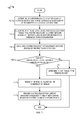
- FIG. 2 is a flow diagram (“flow”) 200 illustrating example operations for implementing a distributed bandwidth control mechanism. The flow begins at the block 202 .
- a network device of a first class of network devices it is determined at a network device of a first class of network devices to transmit a pending packet via a communication medium.
- the DBC powerline device 102 can determine to transmit a pending DBC packet via the PLC medium 120 .
- the flow continues at block 204 .
- a transmission cost associated with the pending packet is determined.
- the bandwidth control unit 114 can analyze the pending DBC packet and can determine the transmission cost associated with the pending DBC packet.
- the bandwidth control unit 114 can determine a transmission time associated with the pending DBC packet to determine the transmission cost.
- the bandwidth control unit 114 may determine the transmission cost by determining a weighted combination of one or more attributes (e.g., priority, type, duration of transmission, transmission rate, total payload size, bandwidth utilization, etc.) of the pending DBC packet. It is noted that various other techniques can be implemented for determining the transmission cost associated with the pending DBC packet.
- the transmission cost associated with the pending DBC packet may be a pre-determined value assigned to the pending DBC packet depending on the type of the packet, the priority of the packet, and/or other attributes. For example, high priority DBC packets may be assigned a cost of “1”, other DBC packets may be assigned a cost of “2”, etc.
- the flow continues at block 206 .
- one or more packets previously transmitted by one or more network devices of the first class of network devices during a predetermined time interval are determined.
- the determined one or more packets previously transmitted during the predetermined time interval can include packets transmitted by the first network device and also packets transmitted by other network devices of the first class of network devices coupled to the communication medium.
- the bandwidth control unit 114 can identify one or more DBC packets previously transmitted by the DBC powerline devices 102 , 104 , and 108 (and other DBC powerline devices on the PLC medium 120 within the PLC network 100 ) during the predetermined time interval.
- the predetermined time interval may be an interval of time that precedes a current time instant.
- the predetermined time interval can be predefined based on device and/or protocol implementations and specifications.
- the predetermined time interval may be selected to be large enough to enable DBC powerline devices to perform a plurality of transmissions during the predetermined time interval (e.g., considering the minimum or average size or duration of DBC device transmissions).
- the predetermined time interval may be selected based on a maximum size or duration of DBC device transmissions.
- the predetermined time interval may be selected to be equal to (or a multiple of) a beacon interval of the DBC powerline device 102 .
- the predetermined time interval could be specified in terms of a length of time (e.g., Xms), as described with reference to FIG. 3A .
- the predetermined time interval could be indicated in terms of a number of bins where each bin corresponds to a subset of the predetermined time interval, as described with reference to FIG. 3B .
- the bandwidth control unit 114 can determine the one or more DBC packets previously transmitted during the predetermined time interval by detecting each DBC packet (transmitted by any of the DBC devices 102 , 104 , and 108 ) and by storing an indication of a transmission cost associated with the detected DBC packet. The flow continues at block 208 .
- the transmission cost corresponding to the one or more packets previously transmitted by network devices of the first class of network devices during the predetermined time interval (“previous transmission cost”) is determined.
- the bandwidth control unit 114 can determine the previous transmission cost associated with the one or more detected DBC packets transmitted by the DBC powerline devices 102 , 104 , and 108 during the predetermined time interval.
- the bandwidth control unit 114 can determine the previous transmission cost by aggregating a transmission time associated with each of the detected DBC packets previously transmitted within the predetermined time interval.
- the bandwidth control unit 114 can take into consideration one or more parameters of the detected DBC packets (e.g., a length of the packet, a transmission rate, a transmit time, bandwidth utilization, etc.) when calculating the previous transmission cost.
- the bandwidth control unit 114 can read a pre-calculated (or pre-assigned) transmission cost associated with the one or more detected DBC packets previously transmitted within the predetermined time interval. For example, the bandwidth control unit 114 can detect a DBC packet on the PLC medium 120 , calculate the transmission cost of the detected DBC packet, and accordingly update the previous transmission cost.
- the DBC powerline device 102 may, itself, calculate the transmission cost associated with each of the detected DBC packets as the DBC packets are detected.
- the bandwidth control unit 114 may read a cost field in a header of a detected DBC packet to determine the transmission cost of the detected DBC packet (calculated by the DBC powerline device that transmitted the detected DBC packet). The flow continues at block 210 .
- a cumulative transmission cost is determined based on the transmission cost associated with transmissions during the predetermined time interval and the transmission cost associated with the pending packet. For example, the bandwidth control unit 114 can sum the previous transmission cost associated with the one or more DBC packets detected during the predetermined time interval (determined at block 208 ) with the transmission cost associated with the pending DBC packet (determined at block 204 ) to yield the cumulative transmission cost. In some implementations, the bandwidth control unit 114 could calculate a weighted sum of the previous transmission cost associated with the one or more DBC packets detected during the predetermined time interval and the transmission cost associated with the pending DBC packet.
- the bandwidth control unit 114 can determine whether the pending DBC packet should be transmitted via the PLC medium 120 . In some implementations, if the DBC powerline device 102 comprises more than one pending DBC packet to be transmitted, the bandwidth control unit 114 can calculate a combined cumulative transmission cost comprising the transmission costs associated with all the pending DBC packets and can determine if all the pending DBC packets can be transmitted. In another implementation, the bandwidth control unit 114 can select one or more of the pending DBC packets to be transmitted based on the priority of the packets, the transmission cost associated with each of the pending DBC packets, available bandwidth for DBC communication, etc. The flow continues at block 212 .
- the bandwidth control unit 114 can determine whether the cumulative transmission cost is greater than the threshold transmission cost allocated for DBC device communication.
- the threshold transmission cost can be determined based on a predefined maximum bandwidth utilization associated with the PLC medium 120 that is allocated for DBC communications. For example, it may be determined that the DBC powerline devices 102 , 104 , and 108 should utilize only 7% of the communication bandwidth of the PLC medium 120 . In this example, if the predetermined time interval is 50 ms, the threshold transmission cost may be 7% of 50 ms (i.e., 3.5 ms).
- the threshold transmission cost allocated for DBC device communication may be calculated as a weighted combination of one or more threshold communication attributes.
- the threshold transmission cost allocated for DBC device communication can be a weighted combination of the threshold time allocated for DBC device communication, the threshold bandwidth utilization allocated for DBC device communication, the maximum DBC packet size, etc. If it is determined that the cumulative transmission cost is less than the threshold transmission cost, the flow continues at block 214 . Otherwise, the flow continues at block 216 .
- the first network device of the first class of network devices transmits the pending packet via the communication medium.
- the transceiver unit 110 can transmit (based on an indication from the bandwidth control unit 114 ) the pending DBC packet via the PLC medium 120 .
- the flow 200 moves from block 212 to block 214 on determining that the threshold transmission cost allocated for DBC device communication will not be exceeded if the pending DBC packet is transmitted.
- the DBC powerline device 102 that generated the pending DBC packet can then contend for the PLC medium 120 (e.g., with the non-DBC powerline device 106 , with other DBC powerline devices 104 , 108 , etc.) and can transmit the pending DBC packet on gaining control of the PLC medium 120 . From block 214 , the flow ends.
- the first network device of the first class of network devices determines to not transmit the pending packet.
- the flow 200 moves from block 212 to block 216 on determining that the threshold transmission cost allocated for DBC device communication will be exceeded if the pending DBC packet is transmitted.
- the bandwidth control unit 114 can determine that the pending DBC packet generated by the DBC powerline device 102 should not be transmitted.
- the bandwidth control unit 114 can cause the transceiver unit 110 to not transmit any subsequent DBC packets until a predetermined wait time interval is elapsed and/or until sufficient bandwidth is available for transmission of the DBC packets.
- the bandwidth control unit 114 can cause the transceiver unit 110 and the DBC powerline device 102 to delay subsequent transmissions until the cumulative transmission cost is reduced by the passage of time.
- FIG. 4 further illustrates DBC powerline devices determining whether to transmit DBC packets based on utilization of bandwidth allocated for DBC device communication. From block 216 , the flow ends.
- FIG. 3A is a conceptual diagram illustrating an example embodiment of a time-interval based DBC protocol, which can be implemented in the PLC network 100 described above with references to FIGS. 1-2 .
- FIG. 3A depicts DBC packets transmitted via the PLC medium 120 (by the DBC devices 102 , 104 , and 108 of the PLC network 100 ) and the transmission cost associated with each of the DBC packets.
- a DBC packet with transmission cost C1 302 is detected on the PLC medium 120 .
- a DBC packet with transmission cost C2 304 is detected at time instant 314
- a DBC packet with transmission cost C3 306 is detected at time instant 316
- a DBC packet with transmission cost Cn 308 is detected at time instant 318 .
- Each of the DBC powerline devices 102 , 104 , and 108 can store information about the time instant at which various packets were detected on the PLC medium 120 and the transmission cost associated with each of the detected DBC packets (for their own transmissions and for transmissions from other DBC powerline devices).
- the predetermined time interval 310 across which the transmission cost of previously transmitted DBC packets is analyzed comprises the time instants 314 , 316 , and 318 .
- the DBC powerline device 102 may determine to transmit a pending DBC packet with transmission cost C p 312 .
- the DBC powerline device 102 e.g., the bandwidth control unit 114
- the DBC powerline device 102 can use the stored information to determine the transmission cost of all the DBC packets transmitted within the predetermined time interval 310 .
- FIG. 3B is a conceptual diagram illustrating an example embodiment of a bin-based DBC protocol, which can be implemented in the PLC network 100 described above with references to FIGS. 1-2 .
- Bins 352 , 354 , 356 , 358 , and 360 constitute the predetermined time interval 310 at current time instant 366 .
- the current time instant 366 falls within current bin 362 .
- each DBC powerline device 102 , 104 , and 108 can maintain a timer to determine bin boundaries.
- the bin boundaries can indicate time instants at which the current bin expires and a new current bin starts. For example, when the bin interval 364 is 5 ms, each DBC powerline device 102 , 104 , and 108 can maintain a 5 ms timer.
- the DBC powerline device can switch to a new current bin at each 5 ms interval, as will be described below.
- each of the DBC powerline devices 102 , 104 , and 108 can track the number of DBC packets transmitted in each of the previous N bins and the number of DBC packets transmitted in the current bin.
- Each DBC powerline device 102 , 104 , and 108 can also maintain a buffer (e.g., a circular buffer) to store the total transmission cost of the DBC packets transmitted/detected in each bin that comprises the predetermined time interval 310 and to store the transmission cost associated with the current bin.
- a buffer e.g., a circular buffer
- each of the DBC powerline devices 102 , 104 , and 108 can store (in the buffer) a transmission cost associated with the previous five bins 352 , 354 , 356 , 358 , and 360 and a transmission cost associated with the current bin 362 .
- the transmission cost associated with each of the previous five bins 352 , 354 , 356 , 358 , and 360 can be accessed from a data structure (or may be calculated on the fly). For example, if three DBC packets were detected in the bin 352 , the transmission cost associated with bin 352 may be a combined transmission cost of the three DBC packets detected during the time interval that corresponds to the bin 352 .
- the transmission costs associated with the previous five bins 352 , 354 , 356 , 358 , and 360 can be summed together to determine the previous transmission cost (S) associated with the DBC packets transmitted during the predetermined time interval 310 .
- the previous transmission cost S and the transmission cost associated with the current bin 362 can be analyzed to determine whether pending DBC packets can be transmitted at the current time instant 366 .
- the sum S calculated above, the transmission cost of the current bin 362 , and the transmission cost of the pending DBC packet can be added to yield the cumulative transmission cost.
- the cumulative transmission cost can be compared against the threshold transmission cost allocated for DBC device communication.
- the maximum bandwidth utilization of the PLC medium 120 allocated for DBC device communication may be 7%. If transmission time is used as a cost function and the predetermined time interval is 30 ms, the DBC powerline devices may cumulatively transmit for only 7% of the 30 ms time interval (i.e., the time interval comprising 5 previous bins and the current bin) or 2.1 ms. If the cumulative transmission cost is greater than the threshold transmission cost, the DBC powerline device 102 can wait until the cumulative transmission cost is no greater than the threshold transmission cost.
- a reference associated with each DBC packet can be used to determine the bin to which the DBC packet should be assigned.
- the transmission cost of the DBC packet can be added to the transmission cost associated with the bin to which the DBC packet is assigned.
- a bin boundary 368 is reached the transmission cost associated with the oldest bin is subtracted from the previous transmission cost S, and the transmission cost associated with the current bin is added to the previous transmission cost S.
- the predetermined time interval 310 is shifted ahead by 5 ms.
- the bin 352 is no longer part of the predetermined time interval 310 and, therefore, should not be considered in determining whether a pending DBC packet can be transmitted.
- the transmission cost associated with the bin 352 can be subtracted from the previous transmission cost S, and the transmission cost associated with the bin 362 can be added to the previous transmission cost S to yield a new value of the previous transmission cost (S′).
- Bin 370 can then be designated as the current bin, the transmission cost associated with the current bin 370 can be initialized to zero, and the transmission cost associated with the current bin 370 can be updated as DBC packets are transmitted/detected in the 5 ms time interval that corresponds to the current bin 370 .
- the bin boundaries maintained by each of the DBC powerline devices 102 , 104 , and 108 may be synchronized. In other implementations, however, the bin boundaries maintained by the DBC powerline devices 102 , 104 , and 108 need not be synchronized. It is also noted that the bin size and the number of bins over which transmission costs associated with the DBC packet are combined may be static or dynamic and may be determined by the requirements of the system in which they are used. In one example, the DBC powerline devices 102 , 104 , and 108 may maintain relatively large sized bins to minimize processing. In another example, the DBC powerline devices 102 , 104 , and 108 may combine DBC packet costs over a small number of bins to minimize storage and computation overhead.
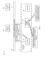
- FIG. 4 is an example sequence diagram illustrating transmission of packets using a distributed bandwidth control protocol.
- FIG. 4 depicts two DBC devices 402 and 412 .
- the DBC devices 402 and 412 can be Green PHY powerline devices or other suitable devices configured for distributed bandwidth control.
- the DBC device 402 maintains a timer (not shown) that indicates logical bin boundaries 408 A- 408 J.
- the DBC device 412 also maintains a timer that indicates its logical bin boundaries 418 A- 418 J.
- the DBC devices 402 and 412 maintain the same bin interval (i.e., the length of the bins maintained at the DBC devices 402 and 412 is the same), the bin boundaries are not synchronized.
- the bin boundaries maintained the DBC device 412 lag the bin boundaries maintained by the DBC device 402 by a fixed delay.
- the DBC device 402 generates and transmits a DBC packet 404 without any delay.
- the DBC packet 404 is transmitted within a first bin bounded by bin boundaries 408 A and 408 B.
- the DBC device 402 can transmit the DBC packet 404 without any delay because the bandwidth allocated for DBC device communication is not exhausted and transmitting the DBC packet 404 will not cause the consumed bandwidth to exceed the bandwidth allocated for DBC device communication.
- the DBC devices 402 and 412 store information regarding bandwidth utilization and the transmitted DBC packet 404 .
- the DBC devices 402 and 412 can store a transmission cost associated with the DBC packet 404 , a current medium utilization, and/or the bandwidth available for subsequent DBC communication.
- the DBC device 412 generates and transmits a DBC packet 414 without any delay because the allocated bandwidth for DBC device communication is not exhausted.
- the DBC packet 414 is transmitted within a third bin (of the DBC device 412 ) bounded by bin boundaries 418 C and 418 D.
- the DBC device 412 can determine whether transmitting the DBC packet 414 will cause the consumed bandwidth to exceed the predefined maximum bandwidth utilization allocated for DBC device communication based on stored bandwidth utilization information (determined at stage B).
- the DBC device 412 transmits the DBC packet 414 without any delay on determining that the bandwidth allocated for DBC device communication is not exhausted and that transmitting the DBC packet 414 will not cause the consumed bandwidth to exceed the allocated bandwidth.
- the DBC devices 402 and 412 can update the information regarding bandwidth utilization and can store information regarding the transmitted DBC packet 414 .
- the DBC devices 402 and 412 determine that bandwidth allocated for DBC device communication is exhausted. For example, the DBC devices 402 and 412 can determine that the transmission time associated with the DBC packet 404 and 414 is equal to (or almost equal to) the threshold transmission time allocated for DBC device communication.
- the DBC device 402 generates a DBC packet 406 but transmission of the DBC packet 406 is delayed until bandwidth is available. Because the DBC device 402 generates the DBC packet 406 after it is determined that the bandwidth allocated for DBC device communication is exhausted, the DBC device 402 cannot transmit the DBC packet 406 without violating DBC protocol constraints (e.g., threshold transmission time allocated for DBC device communication, maximum bandwidth utilization allocated for DBC device communication, etc.). The DBC device 402 can temporarily suspend transmission of the DBC packet 406 and can wait until sufficient bandwidth is available for transmitting the DBC packet 406 to ensure that the consumed bandwidth does not exceed the bandwidth allocated for DBC device communication.
- DBC protocol constraints e.g., threshold transmission time allocated for DBC device communication, maximum bandwidth utilization allocated for DBC device communication, etc.
- the DBC device 412 receives the DBC packet 406 transmitted by the DBC device 402 .
- the DBC device 402 determines that sufficient bandwidth is available for transmitting the DBC packet 406 to the DBC device 412 . Consequently, the DBC device 402 transmits the previously delayed DBC packet 406 .
- the DBC device 412 receives (and subsequently processes) the DBC packet 406 .
- the techniques for distributed bandwidth control can be implemented using a “pay in arrears” approach.
- the “pay in arrears” approach can enable DBC devices to compete equally (or on a priority basis) regardless of the cost of the pending DBC packet and then forbid further transmission until a delay period has elapsed.
- FIG. 5 is a flow diagram 500 illustrating example operations of a delay-based distributed bandwidth control protocol.
- the flow 500 begins at block 502 .
- a network device of a first class of network devices it is determined, at a network device of a first class of network devices, to transmit a pending packet via a communication medium.
- the DBC powerline device 102 can determine to transmit a pending DBC packet via the PLC medium 120 .
- the flow continues at block 504 .
- a transmission cost associated with the pending packet is determined.
- the bandwidth control unit 114 can analyze the pending DBC packet and can determine the transmission cost associated with the pending DBC packet.
- the bandwidth control unit 114 can use any suitable cost function to calculate the transmission cost associated with the pending DBC packet.
- the cost function may be a transmission duration of the pending DBC packet.
- the cost function may be a weighted combination of one or more attributes (e.g., priority, type, duration of transmission, transmission rate, total payload size) of the pending DBC packet.
- a pre-determined cost e.g., a cost of “2” may be assigned to the pending DBC packet (e.g., by an application that generated the DBC packet).
- the flow continues at block 506 .
- the network device transmits the pending packet via the communication medium.
- the transceiver unit 110 can transmit (based on an indication from the bandwidth control unit 114 ) the pending DBC packet via the PLC medium 120 .
- the bandwidth control unit 114 may not analyze the transmission cost associated with the pending DBC packet and the cost of previously transmitted DBC packets (as described above with reference to FIGS. 1-4 ) to determine whether to transmit the pending DBC packet.
- the DBC powerline device 102 can contend for the PLC medium 120 with the non-DBC powerline device 106 , with other DBC powerline devices 104 , 108 , etc. On gaining control of the PLC medium 120 , the DBC powerline device 102 can transmit the pending DBC packet.
- the flow continues at block 508 .
- a delay period associated with the transmitted packet is calculated based on the transmission cost associated with the packet.
- the bandwidth control unit 114 can calculate the delay period associated with the DBC packet (transmitted at block 506 ) based on the transmission cost associated with the DBC packet.
- the bandwidth control unit 114 can calculate the delay period (R) for the transmitted DBC packet based on the transmission cost (C) associated with the DBC packet (calculated at block 504 ).
- the bandwidth control unit 114 can calculate the delay period for the transmitted DBC packet so that the transmitted DBC packet consumes no more than a maximum fractional bandwidth utilization allocated for DBC device communication (F) over a time period (T) that is associated with the transmission cost (C).
- the bandwidth control unit 114 can first calculate the time period T over which to analyze DBC transmissions for maintaining the maximum fractional bandwidth utilization allocated for DBC device communication F.
- the time period T can be calculated so that the transmission cost C (i.e., the transmission time of the DBC packet) is a fraction F of the time period T.
- the maximum fractional bandwidth utilization for DBC communication is 0.07 (i.e., a 7% bandwidth utilization allocated for DBC communication)
- the time period can be calculated to be 10 ms (i.e., 700 microseconds/0.07).
- the delay period R can be calculated by subtracting the transmission cost C from the time period T.
- the delay period R associated with the DBC packet can be computed to be 9.3 ms (i.e., 10 ms-700 microseconds).
- Eq. 1a and Eq. 1b can be combined to yield Eq. 2, which depicts the delay period R associated with the DBC packet as a function of the maximum fractional bandwidth utilization allocated for DBC device communication F and the transmission cost C associated with the DBC packet.
- the flow continues at block 510 .
- the network device determines to not transmit additional packets for at least the calculated delay period.
- the bandwidth control unit 114 can indicate that additional DBC packets should not be transmitted for at least the calculated delay period.
- the DBC powerline device 102 can wait for a time period of 9.3 ms before attempting to transmit another pending DBC packet. Waiting for the delay period after transmitting (or detecting) the DBC packet can enable the DBC powerline devices 102 , 104 , and 108 to maintain the threshold transmission cost allocated for DBC device communication without analyzing previous DBC transmissions (as described above with reference to FIGS. 2-4 ). From block 510 , the flow ends.
- the DBC powerline devices 102 , 104 , and 108 need not wait for the delay period after each DBC packet is transmitted before transmitting the next DBC packet. Instead, the DBC powerline devices 102 , 104 , and 108 can wait for a cumulative delay period after successively transmitting multiple DBC packets, as will be described with reference to FIG. 6 .
- FIG. 6 is a flow diagram 600 illustrating example operations of a second embodiment of the delay-based distributed bandwidth control protocol.
- the flow 600 begins at block 602 .
- a network device of a first class of network devices it is determined, at a network device of a first class of network devices, to transmit a pending packet via a communication medium.
- the DBC powerline device 102 can determine to transmit a pending DBC packet via the PLC medium 120 .
- the flow continues at block 604 .
- a transmission cost associated with the pending packet is determined. As described above with reference to FIG. 5 , in one example, the bandwidth control unit 114 can determine the transmission cost associated with the pending DBC packet. The flow continues at block 606 .
- the network device transmits the pending packet via the communication medium.
- the transceiver unit 110 can transmit the pending DBC packet via the PLC medium 120 .
- the bandwidth control unit 114 may not analyze the transmission cost associated with the pending DBC packet and the cost of previously transmitted DBC packets (as described above with reference to FIGS. 1-4 ) to determine whether to transmit the pending DBC packet.
- the DBC powerline device 102 can contend for the PLC medium 120 and can transmit the pending DBC packet on gaining control of the PLC medium 120 .
- the flow continues at block 608 .
- a delay period associated with the transmitted packet is calculated based on the transmission cost associated with the packet.
- the bandwidth control unit 114 can calculate the delay period associated with the transmitted DBC packet based on the transmission cost associated with the DBC packet.
- the delay period associated with the DBC packet can be calculated in accordance with Eq. 2. In other implementations, any suitable techniques can be employed for calculating the delay period associated with the DBC packet. The flow continues at block 610 .
- a cumulative delay period is calculated based on the delay period associated with the transmitted packet and unfulfilled delay periods associated with packets previously transmitted by network devices of the first class of network devices.
- the bandwidth control unit 114 can calculate the cumulative delay period based on the delay period associated with the DBC packet (transmitted at block 606 ) and unfulfilled delay periods associated with previously transmitted DBC packets.
- the bandwidth control unit 114 can keep track of DBC packets that were transmitted by the DBC powerline device 102 and by the other DBC powerline devices 104 and 108 .
- the bandwidth control unit 114 can also keep track of delay periods (that were not observed or unfulfilled delay periods) associated with the transmitted/detected DBC packets.
- the bandwidth control unit 114 can update the cumulative delay period. This can enable the DBC powerline devices 102 , 104 , and 108 to transmit multiple DBC packets without waiting for a delay period after each transmission (as described above in FIG. 5 ). Instead, in accordance with the operations described with reference to FIG. 6 , the maximum bandwidth utilization allocated for DBC device communication (e.g., 7%) can still be achieved by observing the cumulative delay period as will be described below. The flow continues at block 612 .
- the bandwidth control unit 114 can compare the cumulative delay period against the threshold delay period.
- the threshold delay period can be calculated based on a threshold transmission duration allocated for DBC device communication or based on a threshold bandwidth utilization allocated for DBC device communication.
- the threshold delay period can be calculated using any suitable techniques, while ensuring that the PLC medium 120 is not dominated by the DBC device communication for an excessive period of time. If it is determined that the cumulative delay period is less than threshold delay period, the DBC powerline device 102 can continue to transmit additional DBC packets without observing the delay period and the flow ends. However, if it is determined that the cumulative delay period is not less than threshold delay period, the flow continues at block 614 .
- the network device determines to not transmit additional packets for at least the cumulative delay period. From block 614 , the flow ends.
- the DBC powerline device 102 can determine whether to transmit the pending DBC packet based on comparing the cumulative delay period against the threshold delay period. For example, the DBC powerline device 102 can calculate the delay period associated with the pending DBC packet. The DBC powerline device 102 can then calculate the cumulative delay period based on the unfulfilled delay periods associated with previously transmitted DBC packets and based on the delay period associated with the pending DBC packet. The DBC powerline device 102 can compare the cumulative delay period against the threshold delay period.
- the DBC powerline device 102 can determine not to transmit the pending DBC packet and to instead observe the unfulfilled delay periods associated with previously transmitted DBC packets. If the cumulative delay period does not exceed the threshold delay period, the DBC powerline device 102 can determine to transmit the pending DBC packet.
- FIG. 5 and FIG. 6 describe the DBC powerline device 102 that transmitted the DBC packet (at block 506 and at block 606 ) determining to not transmit subsequent DBC packets for at least the calculated delay period, embodiments are not so limited.
- all other DBC powerline devices 104 and 108 on the PLC medium 120 can execute operations described with reference to blocks 508 and 510 of FIG. 5 (and blocks 608 - 614 of FIG. 6 ) to determine the delay period associated with the transmitted DBC packet(s).
- the DBC powerline devices 104 and 108 could detect the DBC packet transmitted by the DBC powerline device 102 .
- the DBC powerline devices 104 and 108 can determine the cost associated with the detected DBC packet and can calculate the delay period associated with the detected DBC packet. All the DBC powerline devices 102 , 104 and 106 can then prevent transmission of DBC packets for the calculated delay period.
- a hidden node scenario may arise on the PLC medium 120 (or other communication medium, where network devices implement the DBC protocol).
- a first network device and a second network device may not detect each other (i.e., may be “hidden” from each other).
- a third network device may detect both the first network device and the second network device.
- the first network device and the second network device may alternate transmissions so that they adhere to the DBC protocol constraints (e.g., by limiting transmissions to a threshold transmission time or a threshold bandwidth utilization).
- the third network device detects the first and the second network devices, the third network device may not be able to transmit a DBC packet without violating the DBC protocol constraints.
- the third network device may be starved by the first network device and the second network device.
- the starved network device may transmit pending DBC packets irrespective of the DBC protocol constraints in some situations.
- FIG. 7 is a flow diagram 700 illustrating example operations for counteracting network device starvation.
- the flow 700 begins at block 702 .
- a pending packet is scheduled to be transmitted via a communication medium.
- the DBC powerline device 102 can determine that a pending DBC packet is scheduled to be transmitted via the PLC medium 120 .
- the flow continues at block 704 .
- the bandwidth control unit 114 can determine that the DBC powerline device 102 was prevented from transmitting the pending DBC packet by other DBC powerline devices 104 and 108 for at least the threshold starvation duration.
- the bandwidth control unit 114 can start a timer to record the time for which the DBC powerline device 102 is prevented from transmitting the pending DBC packet.
- the bandwidth control unit 114 can also determine whether the DBC powerline device 102 was prevented from transmitting the pending DBC packet because the DBC powerline device could not contend for the PLC medium 120 .
- the threshold starvation duration may be dependent on one or more of a priority of the pending DBC packet, a transmission cost of the pending DBC packet, a number of DBC powerline devices on the PLC medium 120 , amount of non-DBC traffic, a threshold transmission cost allocated for DBC communication, a maximum allowable transmission cost allocated for DBC communication (if different from the threshold transmission cost), and/or other criteria.
- the bandwidth control unit 114 can determine whether the pending DBC packet was starved for a first threshold starvation duration. If the if the pending DBC packet has a low priority, the bandwidth control unit 114 can determine whether the pending DBC packet was starved for a second threshold starvation duration. The flow continues at block 706 .
- a current bandwidth utilization by network devices of the first class of network devices is calculated (“current bandwidth utilization”).
- the bandwidth control unit 114 can calculate the current bandwidth utilization of the PLC medium 120 by DBC powerline devices based on knowledge of the DBC packets detected during a predetermined time interval. As described above with reference to FIGS. 2-4 , the bandwidth control unit 114 can calculate an aggregate DBC transmission time for which DBC packets were transmitted (e.g., by all the DBC powerline devices 102 , 104 , and 108 ) in the predetermined time interval.
- the bandwidth control unit 114 may determine that the current bandwidth utilization by DBC powerline devices is 10%. The flow continues at block 708 .
- the bandwidth control unit 114 can determine whether the current bandwidth utilization of the PLC medium 120 by DBC communication is greater than the maximum bandwidth utilization allocated for DBC device communication.
- the maximum bandwidth utilization for DBC device communication may be pre-allocated and may depend on the number of non-DBC powerline devices on the PLC medium 120 , the priority of non-DBC transmissions relative to the priority of the DBC device communication, etc. For example, if Green PHY powerline devices are configured for distributed bandwidth control, the DBC Green PHY powerline devices may be configured for a maximum bandwidth utilization of 15%.
- the bandwidth control unit 110 can determine that the current bandwidth utilization (e.g., 10%) is less than the maximum bandwidth utilization allocated for DBC device communication (e.g., 15%).
- the maximum bandwidth utilization can be greater than the threshold bandwidth utilization described above with reference to FIGS. 1-6 .
- the threshold bandwidth utilization can be a fraction of the maximum bandwidth utilization.
- the threshold bandwidth utilization that DBC powerline devices use to determine whether to transmit a pending DBC packet may be approximately 50% of the maximum bandwidth utilization (e.g., 7% threshold bandwidth utilization).
- the threshold bandwidth utilization may be equal to the maximum bandwidth utilization. If it is determined that the current bandwidth utilization is greater than the maximum bandwidth utilization allocated for communication by network devices of the first class of network devices, the flow continues at block 710 . Otherwise, the flow continues at block 714 .
- the network device transmits the pending packet via the communication medium.
- the transceiver unit 110 can transmit (based on an indication from the bandwidth control unit 114 ) the pending DBC packet via the PLC medium 120 .
- the DBC powerline device 102 may have been waiting to transmit a pending DBC packet with cost C, may have been starved by the other DBC powerline devices 104 and 108 (for at least the threshold starvation duration), and may calculate a current bandwidth utilization by all DBC powerline devices (L) that is less than the maximum bandwidth utilization (U).
- the DBC powerline device 102 may be permitted to transmit the pending DBC packet of cost C, even though transmitting the pending DBC packet may exceed other threshold costs (e.g., threshold bandwidth utilization, threshold transmission time) allocated for DBC device communication.
- threshold costs e.g., threshold bandwidth utilization, threshold transmission time
- U maximum bandwidth utilization
- a notification of the current bandwidth utilization is provided to the other network devices of the first class of network device.
- the DBC powerline device 102 can provide the notification of the current bandwidth utilization by all the DBC powerline devices to the DBC powerline devices 104 and 108 .
- the hidden DBC powerline devices 104 and 108 may observe only 1 ⁇ 2 the bandwidth utilization observed by the DBC powerline device 102 .
- the DBC powerline device 102 may transmit information to the DBC powerline devices 104 and 108 as a measure of the effective number of hidden DBC powerline devices or as a measure of how oversubscribed the communication medium appears to be to the DBC powerline device 102 .
- the DBC powerline device 102 may provide an indication of the number of hidden DBC powerline devices observed, a number of hidden device clusters (e.g., groups of DBC powerline devices) observed, the current bandwidth utilization, the time interval for which the DBC powerline device 102 has been waiting to transmit the pending DBC packet, and/or other information.
- each of the DBC powerline devices 102 , 104 , and 108 can transmit an indication of the observed bandwidth utilization to the other DBC powerline devices, so that each of the DBC powerline devices can construct a network map and be aware of all the DBC powerline devices.
- the DBC powerline device 102 may indicate a bandwidth utilization of 14%
- the DBC powerline device 104 may indicate a bandwidth utilization of 7%
- the DBC powerline device 108 may indicate a bandwidth utilization of 7%.
- the DBC powerline devices 104 and 108 can identify a hidden node scenario and can accordingly throttle their transmissions.
- the DBC powerline device 102 can determine that the DBC powerline devices 104 and 108 are hidden from each other and can direct the DBC powerline devices 104 and 108 to reduce their transmissions.
- the DBC powerline devices 104 and 108 can scale their transmissions to account for the hidden DBC powerline devices. For example, using the bin-based DBC protocol described in FIGS. 2-4 , the DBC powerline device 102 may calculate a 5 ms bandwidth utilization by DBC powerline devices per 30 ms (i.e., 17% bandwidth utilization), when the threshold bandwidth utilization should be 2 ms per 30 ms (i.e., 7% bandwidth utilization).
- the network device determines to not transmit the pending packet.
- the bandwidth control unit 114 can determine to not transmit the pending DBC packet.
- the flow 700 moves from block 708 to block 714 on determining that the DBC powerline device 102 was starved by the other DBC powerline devices 104 and 108 for the threshold starvation duration and that the current bandwidth utilization exceeded the maximum bandwidth utilization allocated for DBC device communication.
- the DBC powerline device 102 may not transmit the pending DBC packet, the DBC powerline device 102 may provide an indication of the current bandwidth utilization to the other DBC powerline device 104 and 108 (as described above in block 712 ). From block 714 , the flow ends.
- the DBC powerline device 102 may not transmit the notification of the current bandwidth utilization to the other DBC powerline devices 104 and 108 . Instead, the other DBC powerline devices 104 and 108 may detect the DBC packet transmitted by the DBC powerline device 102 and may automatically decrease their transmissions to comply with DBC protocol constraints (e.g., the threshold transmission time, the threshold bandwidth utilization, etc.). In some implementations, the DBC powerline device 102 may be limited in how often it can execute the operations described with reference to FIG. 7 . For example, if the threshold starvation duration is 500 ms, the DBC powerline device 102 may only be allowed to transmit DBC packets (irrespective of DBC protocol constraints) once every 10 seconds.
- DBC protocol constraints e.g., the threshold transmission time, the threshold bandwidth utilization, etc.
- the bandwidth control unit 114 may determine whether the DBC powerline device 102 should be permitted to transmit the pending DBC packet. Permission to transmit the pending DBC packet irrespective of the DBC protocol constraints may depend on the number of non-DBC powerline devices on the PLC medium 120 , whether the non-DBC powerline devices are currently communicating via the PLC medium 120 , and the current bandwidth utilization of the PLC medium 120 by the non-DBC powerline devices.
- the bandwidth control unit 114 may periodically determine whether the DBC powerline device 102 is in a hidden node scenario and/or whether the DBC powerline device 102 is being starved by the other DBC powerline devices 104 and 108 . If the bandwidth control unit 114 determines that the DBC powerline device 102 is being starved, the bandwidth control unit 114 can determine (as described with reference to FIG. 7 ) whether to transmit pending DBC packets irrespective of the DBC protocol constraints.
- the bandwidth control unit 114 may wait until the threshold starvation duration is exceeded and may continue to determine whether the pending DBC packet can be transmitted.
- the bandwidth control unit 114 can execute operations described with reference to FIG. 2 to determine whether the DBC powerline device 102 can transmit the pending DBC packet.
- FIG. 8 is an example conceptual diagram illustrating a centralized bandwidth control mechanism for a class of bandwidth-controlled devices.
- FIG. 8 depicts a PLC network 800 comprising non-DBC powerline devices 802 and 804 , DBC powerline devices 806 and 808 , and a bandwidth control coordinator (BCC) 810 .
- the non-DBC powerline devices 802 and 804 , the DBC powerline devices 806 and 808 , and the bandwidth control coordinator 810 communicate via the PLC medium 120 .
- the DBC powerline devices 806 and 808 are organized into a logical group (i.e., a DBC logical network 812 ) along with the bandwidth control coordinator 810 .
- a logical group i.e., a DBC logical network 812
- the bandwidth control coordinator 810 can comprise greater communication capabilities as compared to the DBC powerline devices 806 and 806 .
- the bandwidth control coordinator 810 can also provide security keys, assign device identifiers, and coordinate communications of the DBC powerline devices 806 and 808 .
- the bandwidth control coordinator 810 detects beacons from the non-DBC powerline devices 802 and 804 and calculates a time interval during which the DBC powerline devices 806 and 808 can communicate.
- the bandwidth control coordinator 810 can determine access control allocation information (e.g., time intervals during which non-DBC transmissions are scheduled) from the beacons transmitted by the non-DBC powerline devices 802 and 804 . Based on the access control allocation information, the bandwidth control coordinator 810 can determine time intervals during which the non-DBC powerline devices will not be communicating.
- the bandwidth control coordinator 810 can determine the time intervals during which the DBC powerline devices 806 and 808 may be permitted to transmit (“DBC communication time interval”) without interfering with the non-DBC powerline devices 802 and 804 .
- DBC communication time interval the time intervals during which the DBC powerline devices 806 and 808 may be permitted to transmit
- the bandwidth control coordinator 810 may be conservative in calculating the DBC communication time intervals.
- the bandwidth control coordinator 810 could negotiate with other bandwidth control coordinators associated with other DBC logical networks to determine the DBC communication time intervals for the DBC logical network 812 .
- the bandwidth control coordinator 810 can also take the transmission time and bandwidth allocated for DBC device communication into consideration to enable maximum utilization of the bandwidth allocated for DBC device communication. In some implementations, while calculating the DBC communication time intervals, the bandwidth control coordinator 810 can determine whether the DBC powerline devices waited for a restricted time interval (e.g., time interval not allocated for DBC communication) to end before transmitting the DBC packet. If so, the time interval that the DBC powerline devices spent waiting can be deducted from the delay period to be observed by the DBC powerline devices after DBC packet transmission.
- a restricted time interval e.g., time interval not allocated for DBC communication
- the bandwidth control coordinator 810 transmits a BCC beacon to the DBC powerline devices 806 and 808 to indicate the DBC communication time intervals.
- the DBC communication time intervals can indicate one or more time periods during which the DBC powerline devices 806 and 808 can transmit DBC packets without interfering with the non-DBC powerline devices 802 and 804 , and with other communication networks.
- the BCC beacon can also comprise other network management information (e.g., to enable the DBC powerline devices to synchronize their local clocks to a Network Time Base (NTB)).
- NTB Network Time Base
- the bandwidth control coordinator 810 can periodically transmit BCC beacons to provide the DBC powerline devices 806 and 808 with the network management information and updated DBC communication time intervals.
- the bandwidth control coordinator 810 may transmit the BCC beacons infrequently (e.g., when information is available) and not in accordance with a predetermined beacon interval.
- the DBC powerline device 806 transmits a pending DBC packet based, in part, on the DBC communication time intervals indicated in the BCC beacon.
- FIGS. 1-8 are examples meant to aid in understanding embodiments and should not be used to limit embodiments or limit scope of the claims. Embodiments may perform additional operations, fewer operations, operations in a different order, operations in parallel, and some operations differently.
- the DBC protocol may be executed only when transmissions from non-DBC devices are detected.
- the DBC devices may execute the DBC protocol irrespective of whether the non-DBC devices are detected.
- a DBC device that detects a non-DBC device may transmit a control message to other DBC devices to identify the detected non-DBC device and to indicate that the DBC protocol should be executed.
- FIG. 1 describes operations for distributed bandwidth control being implemented by powerline communication devices for managing bandwidth utilization in a powerline communication medium
- various other wired and wireless network devices could implement the operations described above.
- legacy WLAN devices could implement the operations described with reference to FIG. 1 to give non-legacy WLAN devices more time on the wireless communication medium.
- a class of any suitable communication devices that are required to limit their consumption of communication medium resources to provide a higher percentage of the communication medium resources to another class of communication devices can be configured to implement the DBC protocol.
- a source DBC powerline device 102 that has just transmitted a DBC packet may be required to wait longer to transmit another DBC packet as compared to other DBC powerline devices 104 and 108 that have not recently transmitted a DBC packet. This can ensure that the source DBC powerline device 102 does not dominate the PLC medium 120 for an extended period of time.
- the source DBC powerline device 102 may be required to wait an additional K bins or to analyze DBC transmissions over a longer time period to determine if the source DBC powerline device 102 can transmit another pending DBC packet (after transmitting a first pending DBC packet).
- the source DBC powerline device 102 may be required to wait for a longer delay period as compared to the other DBC powerline devices 104 and 108 . If multiple DBC packets can be transmitted before a cumulative delay period begins, then each source DBC powerline device 102 that transmitted prior to the cumulative delay period may be required to wait for an additional delay period proportional to the number of DBC packets transmitted.
- some types of DBC packets may be assigned a transmission cost of “0” or may not be taken into consideration when calculating the cumulative transmission cost (or current bandwidth utilization).
- beacon messages transmitted for communication network management may not be taken into consideration while executing the DBC protocol.
- the beacon messages may be transmitted irrespective of whether the DBC protocol constraints will be violated by the transmission of the beacon messages.
- the DBC devices may be permitted to transmit DBC packets irrespective of the threshold transmission cost (or the threshold bandwidth utilization) if there are no non-DBC devices on the communication medium or if the non-DBC devices are currently not transmitting.
- the DBC packets may always be assigned the lowest priority to enable the DBC devices to use excess bandwidth available, while ensuring that transmitting the DBC packets will not limit the bandwidth available for transmitting non-DBC packets.
- an adaptive DBC protocol may be implemented and the bandwidth allocated for DBC device communication may be increased if the bandwidth utilized by the non-DBC powerline devices falls below a minimum threshold.
- the bandwidth allocated for DBC communication may be decreased if the bandwidth utilized by the DBC powerline devices falls below a minimum threshold and/or if the bandwidth utilized by the non-DBC powerline devices exceeds a maximum threshold.
- the DBC powerline devices may transmit their DBC packets even when the allocated bandwidth for DBC communication is exceeded with a less aggressive back-off mechanism to enable non-DBC powerline devices to easily gain control of the communication medium.
- FIG. 7 describes operations for circumventing a hidden node scenario comprising only DBC devices
- a hidden node scenario can result in the DBC devices consuming more than the threshold bandwidth allocated for DBC device communication. For example, if a non-DBC device is flanked by two DBC devices that are hidden from each other, then each of the DBC devices may consume the threshold bandwidth allocated for DBC device communication resulting in an effective bandwidth consumption that is twice the threshold bandwidth allocated for DBC device DBC communication.
- Such a scenario may be overcome by enabling communication between the DBC devices and the non-DBC devices.
- the non-DBC device may transmit a message to request the DBC devices to reduce their bandwidth utilization by 1 ⁇ 2.
- the non-DBC device can transmit an indication of bandwidth utilization by the DBC devices.
- starved devices either DBC or non-DBC devices
- FIG. 8 describes the bandwidth control coordinator 810 managing the DBC logical network 812 comprising only DBC powerline devices 806 and 808 , embodiments are not so limited.
- the DBC powerline devices 806 and 808 and the non-DBC powerline devices 802 and 804 may be part of a common logical network managed by the bandwidth control coordinator 810 .
- the bandwidth control coordinator 810 may be either a DBC powerline device or a non-DBC powerline device.
- the bandwidth control coordinator 810 may restrict the DBC powerline devices 806 and 808 to communicating within DBC communication intervals and may restrict the non-DBC powerline devices 802 and 804 to communicating during non-DBC communication intervals.
- the bandwidth control coordinator 810 may permit the DBC powerline devices 806 and 808 to contend for the PLC medium 120 during certain carrier sense medium access (CSMA) intervals, and preclude the DBC powerline devices 806 and 808 from contending for the PLC medium 120 during time division multiple access (TDMA) intervals.
- CSMA carrier sense medium access
- TDMA time division multiple access
- Embodiments may take the form of an entirely hardware embodiment, an entirely software embodiment (including firmware, resident software, micro-code, etc.) or an embodiment combining software and hardware aspects that may all generally be referred to herein as a “circuit,” “module” or “system.”
- embodiments of the inventive subject matter may take the form of a computer program product embodied in any tangible medium of expression having computer usable program code embodied in the medium.
- the described embodiments may be provided as a computer program product, or software, that may include a machine-readable medium having stored thereon instructions, which may be used to program a computer system (or other electronic device(s)) to perform a process according to embodiments, whether presently described or not, since every conceivable variation is not enumerated herein.
- a machine-readable medium includes any mechanism for storing or transmitting information in a form (e.g., software, processing application) readable by a machine (e.g., a computer).
- a machine-readable medium may be a non-transitory machine-readable storage medium, or a transitory machine-readable signal medium.
- a machine-readable storage medium may include, for example, but is not limited to, magnetic storage medium (e.g., floppy diskette); optical storage medium (e.g., CD-ROM); magneto-optical storage medium; read only memory (ROM); random access memory (RAM); erasable programmable memory (e.g., EPROM and EEPROM); flash memory; or other types of tangible medium suitable for storing electronic instructions.
- a machine-readable signal medium may include a propagated data signal with computer readable program code embodied therein, for example, an electrical, optical, acoustical, or other form of propagated signal (e.g., carrier waves, infrared signals, digital signals, etc.).
- Program code embodied on a machine-readable medium may be transmitted using any suitable medium, including, but not limited to, wireline, wireless, optical fiber cable, RF, or other communications medium.
- Computer program code for carrying out operations of the embodiments may be written in any combination of one or more programming languages, including an object oriented programming language such as Java, Smalltalk, C++ or the like and conventional procedural programming languages, such as the “C” programming language or similar programming languages.
- the program code may execute entirely on a user's computer, partly on the user's computer, as a stand-alone software package, partly on the user's computer and partly on a remote computer or entirely on the remote computer or server.
- the remote computer may be connected to the user's computer through any type of network, including a local area network (LAN), a personal area network (PAN), or a wide area network (WAN), or the connection may be made to an external computer (for example, through the Internet using an Internet Service Provider).
- LAN local area network
- PAN personal area network
- WAN wide area network
- Internet Service Provider for example, AT&T, MCI, Sprint, EarthLink, MSN, GTE, etc.
- FIG. 9 is a block diagram of one embodiment of an electronic device 900 including a mechanism for distributed bandwidth control in a communication network.
- the electronic device 900 can be a powerline communication device configured for distributed bandwidth control.
- the electronic device 900 can be any suitable wired communication device (e.g., an Ethernet device) or wireless communication device (e.g., a WLAN device) configured for distributed bandwidth control.
- the electronic device 900 may be a laptop, a personal computer (PC), a netbook, a mobile phone, a personal digital assistant (PDA), a printer, or other suitable electronic system configured to communicate with other communication devices and to implement a distributed bandwidth control protocol.
- PC personal computer
- PDA personal digital assistant
- the electronic device 900 includes a processor unit 902 (possibly including multiple processors, multiple cores, multiple nodes, and/or implementing multi-threading, etc.).
- the electronic device 900 includes a memory unit 906 .
- the memory unit 906 may be system memory (e.g., one or more of cache, SRAM, DRAM, zero capacitor RAM, Twin Transistor RAM, eDRAM, EDO RAM, DDR RAM, EEPROM, NRAM, RRAM, SONOS, PRAM, etc.) or any one or more of the above already described possible realizations of machine-readable media.
- the electronic device 900 also includes a bus 910 (e.g., PCI, ISA, PCI-Express, HyperTransport®, InfiniBand®, NuBus, AHB, AXI, etc.), and network interfaces 904 that include at least one of a wireless network interface (e.g., a WLAN interface, a Bluetooth® interface, a WiMAX interface, a ZigBee® interface, a Wireless USB interface, etc.) and a wired network interface (e.g., an Ethernet interface, a powerline communication interface, etc.).
- a wireless network interface e.g., a WLAN interface, a Bluetooth® interface, a WiMAX interface, a ZigBee® interface, a Wireless USB interface, etc.
- a wired network interface e.g., an Ethernet interface, a powerline communication interface, etc.
- the electronic device 900 also includes a communication unit 908 .
- the communication unit 908 comprises a transceiver 912 and a bandwidth control unit 914 .
- the communication unit 908 can determine whether to transmit a pending packet based on a transmission cost of the pending packet, a threshold cost allocated for distributed bandwidth control (DBC) devices, and transmission costs of packets transmitted by other DBC devices in a predetermined time interval, as described above with reference to FIGS. 1-7 .
- Any one of these functionalities may be partially (or entirely) implemented in hardware and/or on the processor unit 902 .
- the functionality may be implemented with an application specific integrated circuit, in logic implemented in the processor unit 902 , in a co-processor on a peripheral device or card, etc.
- realizations may include fewer or additional components not illustrated in FIG. 9 (e.g., video cards, audio cards, additional network interfaces, peripheral devices, etc.).
- the processor unit 902 , the memory unit 906 , and the network interfaces 904 are coupled to the bus 910 . Although illustrated as being coupled to the bus 910 , the memory unit 906 may be coupled to the processor unit 902 .
Abstract
Description
C=F*T Eq. 1a
T=C+R Eq. 1b
Claims (31)
Priority Applications (1)
| Application Number | Priority Date | Filing Date | Title |
|---|---|---|---|
| US13/019,765 US9112751B1 (en) | 2010-02-02 | 2011-02-02 | Distributed bandwidth control in a communication network |
Applications Claiming Priority (2)
| Application Number | Priority Date | Filing Date | Title |
|---|---|---|---|
| US30066010P | 2010-02-02 | 2010-02-02 | |
| US13/019,765 US9112751B1 (en) | 2010-02-02 | 2011-02-02 | Distributed bandwidth control in a communication network |
Publications (1)
| Publication Number | Publication Date |
|---|---|
| US9112751B1 true US9112751B1 (en) | 2015-08-18 |
Family
ID=53397258
Family Applications (2)
| Application Number | Title | Priority Date | Filing Date |
|---|---|---|---|
| US13/019,765 Expired - Fee Related US9112751B1 (en) | 2010-02-02 | 2011-02-02 | Distributed bandwidth control in a communication network |
| US13/019,775 Expired - Fee Related US9065668B1 (en) | 2010-02-02 | 2011-02-02 | Distributed bandwidth control in a communication network |
Family Applications After (1)
| Application Number | Title | Priority Date | Filing Date |
|---|---|---|---|
| US13/019,775 Expired - Fee Related US9065668B1 (en) | 2010-02-02 | 2011-02-02 | Distributed bandwidth control in a communication network |
Country Status (1)
| Country | Link |
|---|---|
| US (2) | US9112751B1 (en) |
Cited By (1)
| Publication number | Priority date | Publication date | Assignee | Title |
|---|---|---|---|---|
| US20170019817A1 (en) * | 2012-12-14 | 2017-01-19 | Huawei Technologies Co., Ltd. | Service Provisioning Using Abstracted Network Resource Requirements |
Families Citing this family (1)
| Publication number | Priority date | Publication date | Assignee | Title |
|---|---|---|---|---|
| JP6969454B2 (en) * | 2018-03-13 | 2021-11-24 | オムロン株式会社 | Control device, control method, and control program |
Citations (17)
| Publication number | Priority date | Publication date | Assignee | Title |
|---|---|---|---|---|
| US5175537A (en) | 1990-03-29 | 1992-12-29 | Micro Technology, Inc. | Method and apparatus for scheduling access to a CSMA communication medium |
| US6085216A (en) * | 1997-12-31 | 2000-07-04 | Xerox Corporation | Method and system for efficiently allocating resources for solving computationally hard problems |
| US20010055311A1 (en) | 2000-04-07 | 2001-12-27 | Trachewsky Jason Alexander | Method of determining a collision between a plurality of transmitting stations in a frame-based communications network |
| US20030067940A1 (en) * | 1998-12-31 | 2003-04-10 | Phil Edholm | End node pacing for qos and bandwidth management |
| US20040030797A1 (en) * | 2002-08-12 | 2004-02-12 | Cuneyt Akinlar | Quality of service management in network gateways |
| US20070153916A1 (en) * | 2005-12-30 | 2007-07-05 | Sharp Laboratories Of America, Inc. | Wireless video transmission system |
| US20090096592A1 (en) * | 2007-10-12 | 2009-04-16 | Alpha Networks Inc. | Power line adapter and method of controlling power line adapter operated in power-saving mode |
| US20090290491A1 (en) * | 2008-05-22 | 2009-11-26 | Microsoft Corporation | End-Host Based Network Management System |
| US20100046555A1 (en) * | 2004-03-04 | 2010-02-25 | Verizon Corporate Services Group Inc. | Method and apparatus for information dissemination |
| US20100183104A1 (en) | 2006-02-27 | 2010-07-22 | Cohda Wireless Pty. Ltd | Method and System for Communication in a Wireless Network |
| US20110019563A1 (en) * | 2009-06-12 | 2011-01-27 | Clara Serrano Solsona | Scheduling Traffic in a Communication Channel |
| US20110202910A1 (en) * | 2010-02-15 | 2011-08-18 | General Electric Company | Low cost and flexible energy management system |
| US20120106342A1 (en) | 2010-11-02 | 2012-05-03 | Qualcomm Incorporated | Systems and methods for communicating in a network |
| US20120155260A1 (en) | 2010-12-17 | 2012-06-21 | Cisco Technology Inc. | Dynamic Synchronized Scheduling in a Computer Network |
| US20120275307A1 (en) * | 2008-09-11 | 2012-11-01 | Juniper Networks, Inc. | Methods and apparatus for flow-controllable multi-staged queues |
| US20130077549A1 (en) * | 2007-04-04 | 2013-03-28 | Marvell World Trade Ltd. | Integrated circuit and method with pre-beacon activation time adjustment |
| US8447541B2 (en) * | 2009-01-26 | 2013-05-21 | Geneva Cleantech Inc. | Energy usage monitoring with remote display and automatic detection of appliance including graphical user interface |
-
2011
- 2011-02-02 US US13/019,765 patent/US9112751B1/en not_active Expired - Fee Related
- 2011-02-02 US US13/019,775 patent/US9065668B1/en not_active Expired - Fee Related
Patent Citations (17)
| Publication number | Priority date | Publication date | Assignee | Title |
|---|---|---|---|---|
| US5175537A (en) | 1990-03-29 | 1992-12-29 | Micro Technology, Inc. | Method and apparatus for scheduling access to a CSMA communication medium |
| US6085216A (en) * | 1997-12-31 | 2000-07-04 | Xerox Corporation | Method and system for efficiently allocating resources for solving computationally hard problems |
| US20030067940A1 (en) * | 1998-12-31 | 2003-04-10 | Phil Edholm | End node pacing for qos and bandwidth management |
| US20010055311A1 (en) | 2000-04-07 | 2001-12-27 | Trachewsky Jason Alexander | Method of determining a collision between a plurality of transmitting stations in a frame-based communications network |
| US20040030797A1 (en) * | 2002-08-12 | 2004-02-12 | Cuneyt Akinlar | Quality of service management in network gateways |
| US20100046555A1 (en) * | 2004-03-04 | 2010-02-25 | Verizon Corporate Services Group Inc. | Method and apparatus for information dissemination |
| US20070153916A1 (en) * | 2005-12-30 | 2007-07-05 | Sharp Laboratories Of America, Inc. | Wireless video transmission system |
| US20100183104A1 (en) | 2006-02-27 | 2010-07-22 | Cohda Wireless Pty. Ltd | Method and System for Communication in a Wireless Network |
| US20130077549A1 (en) * | 2007-04-04 | 2013-03-28 | Marvell World Trade Ltd. | Integrated circuit and method with pre-beacon activation time adjustment |
| US20090096592A1 (en) * | 2007-10-12 | 2009-04-16 | Alpha Networks Inc. | Power line adapter and method of controlling power line adapter operated in power-saving mode |
| US20090290491A1 (en) * | 2008-05-22 | 2009-11-26 | Microsoft Corporation | End-Host Based Network Management System |
| US20120275307A1 (en) * | 2008-09-11 | 2012-11-01 | Juniper Networks, Inc. | Methods and apparatus for flow-controllable multi-staged queues |
| US8447541B2 (en) * | 2009-01-26 | 2013-05-21 | Geneva Cleantech Inc. | Energy usage monitoring with remote display and automatic detection of appliance including graphical user interface |
| US20110019563A1 (en) * | 2009-06-12 | 2011-01-27 | Clara Serrano Solsona | Scheduling Traffic in a Communication Channel |
| US20110202910A1 (en) * | 2010-02-15 | 2011-08-18 | General Electric Company | Low cost and flexible energy management system |
| US20120106342A1 (en) | 2010-11-02 | 2012-05-03 | Qualcomm Incorporated | Systems and methods for communicating in a network |
| US20120155260A1 (en) | 2010-12-17 | 2012-06-21 | Cisco Technology Inc. | Dynamic Synchronized Scheduling in a Computer Network |
Non-Patent Citations (3)
| Title |
|---|
| "U.S. Appl. No. 13/019,775 Final Office Action", Dec. 22, 2014, 34 Pages. |
| "U.S. Appl. No. 13/019,775 Office Action", Jun. 20, 2014, 10 pages. |
| Co-Pending U.S. Appl. No. 13/019,775, filed Feb. 2, 2011, 49 pages. |
Cited By (2)
| Publication number | Priority date | Publication date | Assignee | Title |
|---|---|---|---|---|
| US20170019817A1 (en) * | 2012-12-14 | 2017-01-19 | Huawei Technologies Co., Ltd. | Service Provisioning Using Abstracted Network Resource Requirements |
| US11071020B2 (en) * | 2012-12-14 | 2021-07-20 | Huawei Technologies Co., Ltd. | Service provisioning using abstracted network resource requirements |
Also Published As
| Publication number | Publication date |
|---|---|
| US9065668B1 (en) | 2015-06-23 |
Similar Documents
| Publication | Publication Date | Title |
|---|---|---|
| Logeshwaran et al. | L‐RUBI: An efficient load‐based resource utilization algorithm for bi‐partite scatternet in wireless personal area networks | |
| Farag et al. | A delay-bounded MAC protocol for mission-and time-critical applications in industrial wireless sensor networks | |
| CN101193054B (en) | A method and system for data transmission and node devices and coordination device | |
| US9380577B2 (en) | Method and device for collaborative data communication in a radio network | |
| US20120236716A1 (en) | Profile-based quality of service for wireless communication systems | |
| CN101682553A (en) | Communication terminal device and communication control method | |
| US20100195548A1 (en) | Network assisted power management | |
| US10194374B2 (en) | Network join method and network device using the network join method | |
| KR100807529B1 (en) | Method for real-time transmission of wireless fieldbus | |
| JP2008543116A (en) | Power line communication system | |
| US20150092639A1 (en) | Indicating a busy period in a wireless network | |
| KR100813884B1 (en) | Method of accessing media based on probability supporting priority and computer-readable medium having thereon program performing function embodying the same | |
| CN104469855A (en) | Method and device for selecting time slot resources | |
| Pullmann et al. | A new planning-based collision-prevention mechanism in long-range IoT networks | |
| CN101795228A (en) | Bandwidth adjusting method of user and equipment thereof | |
| US9112751B1 (en) | Distributed bandwidth control in a communication network | |
| Semprebom et al. | (m, k)-firm pattern spinning to improve the GTS allocation of periodic messages in IEEE 802.15. 4 networks | |
| Kim et al. | Scheduling of wireless control networks based on IEEE 802.15. 4 networks: Mixed traffic environment | |
| CN105792287B (en) | The protection time slot self-adjusted block and method of evaluating performance of wireless body area network | |
| US8855693B2 (en) | Method and apparatus for controlling wireless devices | |
| JP2009130751A (en) | Resource reservation apparatus, system, and method | |
| Franchino et al. | A power-aware MAC layer protocol for real-time communication in wireless embedded systems | |
| CN105592562A (en) | Asynchronous multi-channel industrial wireless network scheduling method for emergency data | |
| Bhandari et al. | Study on improving the network life time maximazation for wireless sensor network using cross layer approach | |
| Mishra et al. | On scheduling guaranteed time slots for time sensitive transactions in IEEE 802.15. 4 networks |
Legal Events
| Date | Code | Title | Description |
|---|---|---|---|
| AS | Assignment |
Owner name: ATHEROS COMMUNICATIONS, INC., CALIFORNIA Free format text: ASSIGNMENT OF ASSIGNORS INTEREST;ASSIGNORS:KATAR, SRINIVAS;YONGE, LAWRENCE W., III;ZYREN, JAMES G.;SIGNING DATES FROM 20110202 TO 20110411;REEL/FRAME:026124/0373 |
|
| AS | Assignment |
Owner name: QUALCOMM, INCORPORATED, CALIFORNIA Free format text: MERGER;ASSIGNOR:ATHEROS COMMUNICATIONS, INC.;REEL/FRAME:026763/0770 Effective date: 20110524 |
|
| AS | Assignment |
Owner name: QUALCOMM ATHEROS, INC., CALIFORNIA Free format text: CORRECTIVE ASSIGNMENT TO CORRECT THE RECEIVING PARTY PREVIOUSLY RECORDED ON REEL 026763 FRAME 0770. ASSIGNOR(S) HEREBY CONFIRMS THE MERGER;ASSIGNOR:ATHEROS COMMUNICATIONS, INC.;REEL/FRAME:026770/0064 Effective date: 20110524 |
|
| AS | Assignment |
Owner name: QUALCOMM INCORPORATED, CALIFORNIA Free format text: ASSIGNMENT OF ASSIGNORS INTEREST;ASSIGNOR:QUALCOMM ATHEROS, INC.;REEL/FRAME:029394/0660 Effective date: 20121022 |
|
| STCF | Information on status: patent grant |
Free format text: PATENTED CASE |
|
| FEPP | Fee payment procedure |
Free format text: MAINTENANCE FEE REMINDER MAILED (ORIGINAL EVENT CODE: REM.); ENTITY STATUS OF PATENT OWNER: LARGE ENTITY |
|
| LAPS | Lapse for failure to pay maintenance fees |
Free format text: PATENT EXPIRED FOR FAILURE TO PAY MAINTENANCE FEES (ORIGINAL EVENT CODE: EXP.); ENTITY STATUS OF PATENT OWNER: LARGE ENTITY |
|
| STCH | Information on status: patent discontinuation |
Free format text: PATENT EXPIRED DUE TO NONPAYMENT OF MAINTENANCE FEES UNDER 37 CFR 1.362 |
|
| FP | Lapsed due to failure to pay maintenance fee |
Effective date: 20190818 |