US9019234B2 - Non-screen capacitive touch surface for bookmarking an electronic personal display - Google Patents
Non-screen capacitive touch surface for bookmarking an electronic personal display Download PDFInfo
- Publication number
- US9019234B2 US9019234B2 US14/015,739 US201314015739A US9019234B2 US 9019234 B2 US9019234 B2 US 9019234B2 US 201314015739 A US201314015739 A US 201314015739A US 9019234 B2 US9019234 B2 US 9019234B2
- Authority
- US
- United States
- Prior art keywords
- capacitive touch
- ereader
- pinch
- personal display
- electronic personal
- Prior art date
- Legal status (The legal status is an assumption and is not a legal conclusion. Google has not performed a legal analysis and makes no representation as to the accuracy of the status listed.)
- Active, expires
Links
Images


Classifications
-
- G—PHYSICS
- G06—COMPUTING; CALCULATING OR COUNTING
- G06F—ELECTRIC DIGITAL DATA PROCESSING
- G06F3/00—Input arrangements for transferring data to be processed into a form capable of being handled by the computer; Output arrangements for transferring data from processing unit to output unit, e.g. interface arrangements
- G06F3/01—Input arrangements or combined input and output arrangements for interaction between user and computer
- G06F3/048—Interaction techniques based on graphical user interfaces [GUI]
- G06F3/0487—Interaction techniques based on graphical user interfaces [GUI] using specific features provided by the input device, e.g. functions controlled by the rotation of a mouse with dual sensing arrangements, or of the nature of the input device, e.g. tap gestures based on pressure sensed by a digitiser
- G06F3/0488—Interaction techniques based on graphical user interfaces [GUI] using specific features provided by the input device, e.g. functions controlled by the rotation of a mouse with dual sensing arrangements, or of the nature of the input device, e.g. tap gestures based on pressure sensed by a digitiser using a touch-screen or digitiser, e.g. input of commands through traced gestures
- G06F3/04883—Interaction techniques based on graphical user interfaces [GUI] using specific features provided by the input device, e.g. functions controlled by the rotation of a mouse with dual sensing arrangements, or of the nature of the input device, e.g. tap gestures based on pressure sensed by a digitiser using a touch-screen or digitiser, e.g. input of commands through traced gestures for inputting data by handwriting, e.g. gesture or text
-
- G—PHYSICS
- G06—COMPUTING; CALCULATING OR COUNTING
- G06F—ELECTRIC DIGITAL DATA PROCESSING
- G06F3/00—Input arrangements for transferring data to be processed into a form capable of being handled by the computer; Output arrangements for transferring data from processing unit to output unit, e.g. interface arrangements
- G06F3/01—Input arrangements or combined input and output arrangements for interaction between user and computer
- G06F3/03—Arrangements for converting the position or the displacement of a member into a coded form
- G06F3/041—Digitisers, e.g. for touch screens or touch pads, characterised by the transducing means
- G06F3/044—Digitisers, e.g. for touch screens or touch pads, characterised by the transducing means by capacitive means
- G06F3/0443—Digitisers, e.g. for touch screens or touch pads, characterised by the transducing means by capacitive means using a single layer of sensing electrodes
-
- G—PHYSICS
- G06—COMPUTING; CALCULATING OR COUNTING
- G06F—ELECTRIC DIGITAL DATA PROCESSING
- G06F2203/00—Indexing scheme relating to G06F3/00 - G06F3/048
- G06F2203/033—Indexing scheme relating to G06F3/033
- G06F2203/0339—Touch strips, e.g. orthogonal touch strips to control cursor movement or scrolling; single touch strip to adjust parameter or to implement a row of soft keys
-
- G—PHYSICS
- G06—COMPUTING; CALCULATING OR COUNTING
- G06F—ELECTRIC DIGITAL DATA PROCESSING
- G06F2203/00—Indexing scheme relating to G06F3/00 - G06F3/048
- G06F2203/048—Indexing scheme relating to G06F3/048
- G06F2203/04808—Several contacts: gestures triggering a specific function, e.g. scrolling, zooming, right-click, when the user establishes several contacts with the surface simultaneously; e.g. using several fingers or a combination of fingers and pen
Definitions
- FIG. 1A shows a front perspective view of an electronic reader (eReader), in accordance with various embodiments.
- FIG. 1B shows a rear perspective view of the eReader of FIG. 1A , in accordance with various embodiments.
- FIG. 2A shows a cross-section of the eReader of FIG. 1A along with a detail view of a portion of the display of the eReader, in accordance with various embodiments.
- FIG. 3 shows a cutaway view of an eReader illustrating one example of a touch sensor, in accordance with an embodiment.
- FIG. 4 shows an example computing system which may be included as a component of an eReader, according to various embodiments.
- FIG. 5 shows a block diagram of a capacitive touch surface bookmarking system for an electronic personal display, in accordance with an embodiment.
- FIG. 6 illustrates a flow diagram of a method for utilizing a non-screen capacitive touch surface for bookmarking an electronic personal display, according to various embodiments.
- the electronic computing device/system manipulates and transforms data represented as physical (electronic) quantities within the circuits, electronic registers, memories, logic, and/or components and the like of the electronic computing device/system into other data similarly represented as physical quantities within the electronic computing device/system or other electronic computing devices/systems.
- the housing of the electronic personal display includes capacitive touch sensors.
- the electronic personal display monitors the capacitive touch sensors for a pinch and slide type contact. When the device is appropriately “pinched” and the pinch is then slid along the capacitive touch sensors, a bookmarking action is performed. In general, a “pinch” occurs when the device is concurrently touched from at least two overlapping non-planar points.
- One example of a concurrent touching that occurs from at least two overlapping non-planner points would be the touching of a front side surface at a point approximately 1 inch down from the top of the device and, at the same time, a touching of a back side surface at a point approximately 1 inch down from the top of the device.
- the touches are concurrent because they occur at the same time, they are overlapping because they both occur at a point approximately 1 inch down from the top of the device, and they are non-planner because they occur on two different planes (e.g., the front surface plane and the back surface plane).
- the “slide” occurs when the “pinch” is drug along a portion of the capacitive touch sensors in a pre-determined direction for a pre-defined distance.
- the bookmarking trigger is based on capacitive touch sensor interaction and possibly a predetermined pattern of motion contemporaneous with maintaining the touch contact with the touch-sensitive surface, an actual physical button, an actual physical button is not required on the electronic personal display. By removing any buttons on the device, a greater robustness with regard to dust, fluid contaminants and the like can be achieved.
- the electronic personal display is an eReader.
- Discussion will begin with description of an example eReader and various components that may be included in some embodiments of an eReader. Various display and touch sensing technologies that may be utilized with some embodiments of an eReader will then be described. An example computing system, which may be included as a component of an eReader, will then be described. Operation of an example eReader and several of its components will then be described in more detail in conjunction with a description of an example method of utilizing a non-screen capacitive touch surface for bookmarking an electronic personal display.
- FIG. 1A shows a front perspective view of an eReader 100 , in accordance with various embodiments.
- eReader 100 is one example of an electronic personal display.
- an eReader is discussed specifically herein for purposes of example, concepts discussed are equally applicable to other types of electronic personal displays such as, but not limited to, mobile digital devices/tablet computers and/or multimedia smart phones.
- eReader 100 includes a display 120 , a housing 110 , and some form of on/off switch 130 .
- eReader 100 may further include one or more of: speakers 150 ( 150 - 1 and 150 - 2 depicted), microphone 160 , digital camera 170 , 3D motion sensor 175 and removable storage media slot 180 .
- Section lines depict a region and direction of a section A-A which is shown in greater detail in FIG. 2A .
- Housing 110 forms an external shell in which display 120 is situated and which houses electronics and other components that are included in an embodiment of eReader 100 .
- a front surface 111 , a bottom surface 112 , and a right side surface 113 are visible.
- housing 110 may be formed of a plurality of joined or inter-coupled portions.
- Housing 110 may be formed of a variety of materials such as plastics, metals, or combinations of different materials.
- Display 120 has an outer surface 121 (sometimes referred to as a bezel) through which a user may view digital contents such as alphanumeric characters and/or graphic images that are displayed on display 120 .
- Display 120 may be any one of a number of types of displays including, but not limited to: a liquid crystal display, a light emitting diode display, a plasma display, a bistable display or other display suitable for creating graphic images and alphanumeric characters recognizable to a user.
- On/off switch 130 is utilized to power on/power off eReader 100 .
- On/off switch 130 may be a slide switch (as depicted), button switch, toggle switch, touch sensitive switch, or other switch suitable for receiving user input to power on/power off eReader 100 .
- Speaker(s) 150 when included, operates to emit audible sounds from eReader 100 .
- a speaker 150 may reproduce sounds from a digital file stored on or being processed by eReader 100 and/or may emit other sounds as directed by a processor of eReader 100 .
- Microphone 160 when included, operates to receive audible sounds from the environment proximate eReader 100 . Some examples of sounds that may be received by microphone 160 include voice, music, and/or ambient noise in the area proximate eReader 100 . Sounds received by microphone 160 may be recorded to a digital memory of eReader 100 and/or processed by a processor of eReader 100 .
- Digital camera 170 when included, operates to receive images from the environment proximate eReader 100 .
- Some examples of images that may be received by digital camera 170 include an image of the face of a user operating eReader 100 and/or an image of the environment in the field of view of digital camera 170 .
- Images received by digital camera 170 may be still or moving and may be recorded to a digital memory of eReader 100 and/or processed by a processor of eReader 100 .
- Removable storage media slot 180 when included, operates to removably couple with and interface to an inserted item of removable storage media, such as a non-volatile memory card (e.g., MultiMediaCard (“MMC”), a secure digital (“SD”) card, or the like).
- MMC MultiMediaCard
- SD secure digital
- Digital content for play by eReader 100 and/or instructions for eReader 100 may be stored on removable storage media inserted into removable storage media slot 180 . Additionally or alternatively, eReader 100 may record or store information on removable storage media inserted into removable storage media slot 180 .
- FIG. 1B shows a rear perspective view of eReader 100 of FIG. 1A , in accordance with various embodiments.
- a rear surface 115 of the non-display side of the housing 110 of eReader 100 is visible.
- a left side surface 114 of housing 110 is also visible in FIG. 1B .
- housing 110 also includes a top surface which is not visible in either FIG. 1A or FIG. 1B .
- FIG. 2A shows a cross-section A-A of eReader 100 along with a detail view 220 of a portion of display 120 , in accordance with various embodiments.
- a plurality of touch sensors 230 are visible and illustrated in block diagram form. It should be appreciated that a variety of touch sensing technologies may be utilized to form touch sensors 230 that are included in embodiments of eReader 100 ; these include, but are not limited to: resistive touch sensors; capacitive touch sensors (using self and/or mutual capacitance); inductive touch sensors; and infrared touch sensors.
- resistive touch sensing responds to pressure applied to a touched surface and is implemented using a patterned sensor design on, within, or beneath display 120 , rear surface 115 , and/or other surface of housing 110 .
- inductive touch sensing requires the use of a stylus and are implemented with a patterned electrode array disposed on, within, or beneath display 120 , rear surface 115 , and/or other surface of housing 110
- capacitive touch sensing utilizes a patterned electrode array disposed on, within, or beneath display 120 , rear surface 115 , and/or other surface of housing 110 ; and the patterned electrodes sense changes in capacitance caused by the proximity or contact by an input object.
- infrared touch sensing operates to sense an input object breaking one or more infrared beams that are projected over a surface such as outer surface 121 , rear surface 115 , and/or other surface of housing 110 .
- a touch sensor 230 Once an input object interaction is detected by a touch sensor 230 , it is interpreted either by a special purpose processor (e.g., an application specific integrated circuit (ASIC)) that is coupled with the touch sensor 230 and the interpretation is passed to a processor of eReader 100 , or a processor of eReader is used to directly operate and/or interpret input object interactions received from a touch sensor 230 .
- ASIC application specific integrated circuit
- patterned sensors and/or electrodes may be formed of optically transparent material such as very thin wires or a material such as indium tin oxide (ITO).
- one or more touch sensors 230 may be included in eReader 100 in order to receive user input from input object such 201 such as styli or human digits.
- input object such as styli or human digits.
- user input from one or more fingers such as finger 201 - 1 may be detected by touch sensor 230 - 1 and interpreted.
- Such user input may be used to interact with graphical content displayed on display 120 and/or to provide other input through various gestures (e.g., tapping, swiping, pinching digits together on outer surface 121 , spreading digits apart on outer surface 121 , or other gestures).
- various gestures e.g., tapping, swiping, pinching digits together on outer surface 121 , spreading digits apart on outer surface 121 , or other gestures.
- the touch sensitivity is also capable of directional discrimination as well as extent of motion.
- the gesture may be interpreted based on directionality and length or time that contact is maintained during the gesture action.
- a touch sensor 230 - 2 may be disposed proximate rear surface 115 of housing 110 in order to receive user input from one or more input objects 201 , such as human digit 201 - 2 . In this manner, user input may be received across all or a portion of the rear surface 115 in response to proximity or touch contact with rear surface 115 by one or more user input objects 201 . In some embodiments, where both front ( 230 - 1 ) and rear ( 230 - 2 ) touch sensors are included, a user input may be received and interpreted from a combination of input object interactions with both the front and rear touch sensors.
- a left side touch sensor 230 - 3 and/or a right side touch sensor 230 - 4 when included, may be disposed proximate the respective left and/or right side surfaces ( 113 , 114 ) of housing 110 in order to receive user input from one or more input objects 201 .
- user input may be received across all or a portion of the left side surface 113 and/or all or a portion of the right side surface 114 of housing 110 in response to proximity or touch contact with the respective surfaces by or more user input objects 201 .
- a left side touch sensor 230 - 3 and/or a right side touch sensor 230 - 4 may be a continuation of a front touch sensor 230 - 1 or a rear touch sensor 230 - 2 which is extended so as to facilitate receipt proximity/touch user input from one or more sides of housing 110 .
- one or more touch sensors 230 may be similarly included and situated in order to facilitate receipt of user input from proximity or touch contact by one or more user input objects 201 with one or more portions of the bottom 112 and/or top surfaces of housing 110 .
- a detail view 220 is show of display 120 , according to some embodiments.
- Detail 220 depicts a portion of a bistable electronic ink that is used, in some embodiments, when display 120 is a bistable display.
- a bistable display is utilized in eReader 100 as it presents a paper and ink like image and/or because it is a reflective display rather than an emissive display and thus can present a persistent image on display 120 even when power is not supplied to display 120 .
- a bistable display comprises electronic ink the form of millions of tiny optically clear capsules 223 that are filled with an optically clear fluid 224 in which positively charged white pigment particles 225 and negatively charged black pigment particles 226 are suspended.
- the capsules 223 are disposed between bottom electrode 222 and a transparent top electrode 221 .
- a transparent/optically clear protective surface is often disposed over the top of top electrode 221 and, when included, this additional transparent surface forms outer surface 121 of display 120 and forms a touch surface for receiving touch inputs.
- one or more intervening transparent/optically clear layers may be disposed between top electrode 221 and top electrode 221 .
- one or more of these intervening layers may include a patterned sensor and/or electrodes for touch sensor 230 - 1 .
- FIG. 2B shows a front perspective view of an eReader with a pinch and slide type of contact, in accordance with various embodiments.
- FIG. 2B includes an eReader 100 such as described in FIG. 1A .
- FIG. 2B includes a pinch type contact similar to that shown in FIG. 2A as represented by digits 201 - 1 and 201 - 2 .
- hand 251 - 1 is also shown for purposes of clarity.
- a direction of the sliding motion 261 is also shown.
- the hand 251 - 1 is shown as a right hand and the pinch is shown between the thumb and forefinger, either hand may be utilized to perform the maneuver. In addition, any combination of the fingers and/or thumb may be utilized to perform the pinch. Moreover, although the pinch and slide of FIG. 2B is shown occurring on the right front and rear sides of eReader 100 , the pinch and slide may be predefined or user adjustable to any of the sides of eReader 100 including, front right, left, rear, top and bottom.
- the pinch may occur on a first side of eReader 100 and then the slide may be defined as occurring around a corner of eReader 100 .
- the user may pinch the top right front surface 111 and the top right rear surface 115 of eReader 100 and then slide the pinch along the top, around the corner and along either the right or left side of front surface 111 and rear surface 115 of eReader 100 .
- the pinch may be between to perpendicular surfaces.
- digit 201 - 1 may contact right side surface 113 while digit 201 - 2 may contact rear surface 115 .
- the bookmarking gesture would consist of a perpendicular pinch followed by a slide along the two perpendicular surfaces.
- FIG. 3 shows a cutaway view of an eReader illustrating one example of a touch sensor 230 , in accordance with an embodiment.
- a portion of display 120 has been removed such that a portion of underlying top sensor 230 - 1 is visible.
- top touch sensor 230 - 1 is illustrated as an x-y grid of sensor electrodes which may be used to perform various techniques of capacitive sensing.
- sensor electrodes 331 ( 331 - 0 , 331 - 1 , 331 - 2 , and 331 - 3 visible) are arrayed along a first axis
- sensor electrodes 332 ( 332 - 0 , 332 - 1 , 332 - 2 , and 332 - 3 visible) are arrayed along a second axis that is approximately perpendicular to the first axis.
- a dielectric layer (not illustrated) is disposed between all or portions of sensor electrodes 331 and 332 to prevent shorting.
- FIG. 3 has been provided an example only, that a variety of other patterns may be similarly utilized, and some of these patterns may only utilize sensor electrodes disposed in a single layer. Additionally, while the example of FIG. 3 illustrates top sensor 230 - 1 as being disposed beneath display 120 , in other embodiments, portions of touch sensor 230 - 1 may be transparent and disposed either above display 120 or integrated with display 120 .
- a first profile of any input object contacting outer surface 121 can be formed, and then a second profile of any input object contacting outer surface 121 can be formed on an orthogonal axis by performing absolute/self-capacitive sensing on sensor electrodes 332 .
- These capacitive profiles can be processed to determine an occurrence and/or location of a user input with made by means of an input object 201 contacting or proximate outer surface 121 .
- a capacitive image can be formed of any input object contacting outer surface 121 .
- This capacitive image can be processed to determine occurrence and/or location of user input made by means of an input object contacting or proximate outer surface 121 .
- mutual capacitive sensing is regarded as a better technique for detecting multiple simultaneous input objects in contact with a surface such as outer surface 121
- absolute capacitive sensing is regarded as a better technique for proximity sensing of objects which are near but not necessarily in contact with a surface such as outer surface 121 .
- capacitive sensing and/or another touch sensing technique may be used to sense touch input across all or a portion of the rear surface 115 of eReader 100 , and/or any other surface(s) of housing 110 .
- FIG. 4 shows an example computing system 400 which may be included as a component of an eReader, according to various embodiments and with which or upon which various embodiments described herein may operate.
- FIG. 4 illustrates one example of a type of computer (computer system 400 ) that can be used in accordance with or to implement various embodiments of an eReader, such as eReader 100 , which are discussed herein. It is appreciated that computer system 400 of FIG. 4 is only an example and that embodiments as described herein can operate on or within a number of different computer systems.
- System 400 of FIG. 4 includes an address/data bus 404 for communicating information, and a processor 406 A coupled to bus 404 for processing information and instructions. As depicted in FIG. 4 , system 400 is also well suited to a multi-processor environment in which a plurality of processors 406 A, 406 B, and 406 C are present. Processors 406 A, 406 B, and 406 C may be any of various types of microprocessors. For example, in some multi-processor embodiments, one of the multiple processors may be a touch sensing processor and/or one of the processors may be a display processor. Conversely, system 400 is also well suited to having a single processor such as, for example, processor 406 A.
- System 400 also includes data storage features such as a computer usable volatile memory 408 , e.g., random access memory (RAM), coupled to bus 404 for storing information and instructions for processors 406 A, 406 B, and 406 C.
- System 400 also includes computer usable non-volatile memory 410 , e.g., read only memory (ROM), coupled to bus 404 for storing static information and instructions for processors 406 A, 406 B, and 406 C.
- a data storage unit 412 e.g., a magnetic or optical disk and disk drive
- Computer system 400 of FIG. 4 is well adapted to having peripheral computer-readable storage media 402 such as, for example, a floppy disk, a compact disc, digital versatile disc, universal serial bus “flash” drive, removable memory card, and the like coupled thereto.
- computer-readable storage media 402 may be coupled with computer system 400 (e.g., to bus 404 ) by insertion into removable a storage media slot, such as removable storage media slot 180 depicted in FIGS. 1A and 1B .
- System 400 also includes or couples with display 120 for visibly displaying information such as alphanumeric text and graphic images.
- system 400 also includes or couples with one or more optional touch sensors 230 for communicating information, cursor control, gesture input, command selection, and/or other user input to processor 406 A or one or more of the processors in a multi-processor embodiment.
- system 400 also includes or couples with one or more optional speakers 150 for emitting audio output.
- system 400 also includes or couples with an optional microphone 160 for receiving/capturing audio inputs.
- system 400 also includes or couples with an optional digital camera 170 for receiving/capturing digital images as an input.
- Optional touch sensor(s) 230 allows a user of computer system 400 (e.g., a user of an eReader of which computer system 400 is a part) to dynamically signal the movement of a visible symbol (cursor) on display 120 and indicate user selections of selectable items displayed on display 120 .
- a cursor control device and/or user input device may also be included to provide input to computer system 400 , a variety of these include: trackballs, keypads, directional keys, and the like.
- System 400 is also well suited to having a cursor directed or user input received by other means such as, for example, voice commands received via microphone 160 .
- System 400 also includes an input/output (I/O) device 420 for coupling system 400 with external entities.
- I/O input/output
- I/O device 420 is a modem for enabling wired communications or modem and radio for enabling wireless communications between system 400 and an external device and/or external network such as, but not limited to, the Internet.
- I/O device 120 may include a short-range wireless radio such as a Bluetooth® radio, Wi-Fi radio (e.g., a radio compliant with Institute of Electrical and Electronics Engineers' (IEEE) 802.11 standards), or the like.
- IEEE Institute of Electrical and Electronics Engineers'
- an operating system 422 applications 424 , modules 426 , and/or data 428 are shown as typically residing in one or some combination of computer usable volatile memory 408 (e.g., RAM), computer usable non-volatile memory 410 (e.g., ROM), and data storage unit 412 .
- computer usable volatile memory 408 e.g., RAM
- computer usable non-volatile memory 410 e.g., ROM
- data storage unit 412 data storage unit 412 .
- all or portions of various embodiments described herein are stored, for example, as an application 424 and/or module 426 in memory locations within RAM 408 , ROM 410 , computer-readable storage media within data storage unit 412 , peripheral computer-readable storage media 402 , and/or other tangible computer readable storage media.
- FIG. 5 a block diagram of a capacitive touch housing bookmarker 500 for an electronic personal display is shown in accordance with an embodiment.
- One example of an electronic personal display is an electronic reader (eReader).
- capacitive touch housing bookmarker 500 includes a capacitive touch sensing surface 230 on at least two non-planar portions of housing 110 of the electronic personal display, a monitoring module 510 and an operation module 530 that provides an action 555 .
- a capacitive touch sensing surface 230 on at least two non-planar portions of housing 110 of the electronic personal display includes a monitoring module 510 and an operation module 530 that provides an action 555 .
- the components are shown as distinct objects in the present discussion, it is appreciated that the operations of one or more of the components may be combined into a single module.
- the actions performed by a single module described herein could also be broken up into actions performed by a number of different modules or performed by a different module altogether. The present breakdown of assigned actions and distinct modules are merely provided herein for purposes of clarity.
- capacitive touch sensing surface 230 is located on an at least one edge of housing 110 . In another embodiment, capacitive touch sensing surface 230 is located on at least a rear surface 115 of housing 110 . In yet another embodiment, capacitive touch sensing surface 230 covers the entire housing 110 . In general, the capabilities and characteristics of capacitive touch sensing surface 230 on at least two non-planar portions of a housing 110 of the electronic personal display are described in detail herein in the discussion of FIGS. 1-3 . As such, for purposes of clarity, instead of repeating the discussion provided in respect to FIGS. 1-3 , the discussion of FIGS. 1-3 is incorporated by reference in its entirety herein.
- monitoring module 510 monitors output from capacitive touch sensing surface 230 . For example, when a touch 503 , such as by finger 201 - 1 , occurs a signal is output from the capacitive touch sensing surface 230 in the area that was touched. Monitoring module 520 monitor the capacitive touch sensing surface 230 on at least two non-planar portions of a housing 110 and correlates the gesture with a bookmarking action to be performed by the electronic personal display. In general, the gesture-action correlation may be factory set, user adjustable, user selectable, or the like. Once a gesture-action correlation is determined, monitoring module 510 provides an input to operation module 530 to initiate the requested action. Operation module 530 then initiates the action 555 .
- the pinch and slide type contact may be a factory defined gesture or a user definable metric.
- the pinch type contact is noted by correlating contact from at least two non-planar points.
- the contact may be a perpendicular contact or a contact between to generally opposite sides.
- a pinch type contact is similar to that shown in FIGS. 2A and 2B .
- the slide 261 is shown in FIG. 2B by 201 - 2 and 201 - 2 of hand 251 - 1 being drawn along the two generally opposite points.
- slide 261 may be along the entire length of the surfaces. In another embodiment, slide 261 may be performed along a substantial length of the surfaces.
- slide 261 may be any distance that is less than a certain length.
- slide 261 may be any distance less than 25% of the length of the side.
- the length of slide 261 and/or the location of the initial pinch location may be user adjustable.
- the “add a bookmark” gesture is defined as: overlapping contact that includes a touch on the top right front surface 111 and the top right rear surface 115 (e.g., with reference to FIG. 1B , the portion of rear surface 115 which is directly behind the pinched portion of front surface 111 ) and then slide 261 along at least a portion of the top right front surface 11 and the top right rear surface 115 .
- monitoring module 510 receives the signals from capacitive touch sensing surface 230 , monitoring module 510 will determine that a pinch contact that includes a touch on the top right front surface 111 and the top right rear surface 115 along with a maintained pinch that is “slid” along at least a portion of the surfaces 111 and 115 has occurred.
- Monitoring module 510 will correlate the gesture with the action “add a bookmark” and signal operation module 530 to perform the action “add a bookmark”.
- the “add a bookmark” gesture is defined as: overlapping perpendicular contact that includes a touch on the top of right front surface 111 and the top of right side surface 113 and then slide 261 occurs along at least a portion of right front surface 111 and right side surface 113 .
- monitoring module 510 receives the signals from capacitive touch sensing surface 230 , monitoring module 510 will determine that a pinch contact that includes a touch on the top right front surface 111 and the top right surface 113 along with a slide 261 along at least a portion of the surfaces 111 and 113 has occurred.
- Monitoring module 510 will correlate the gesture with the action “add a bookmark” and signal operation module 530 to perform the action “add a bookmark”.
- monitoring module 510 receives signals from capacitive touch sensing surface 230 that indicate non-overlapping contact including a touch on the top right front surface 111 and the top right rear surface 115 has occurred. Monitoring module 510 will determine that the non-overlapping gesture is associated with no bookmarking action. As such, monitoring module 510 will not signal operation module 530 and no action will be performed.
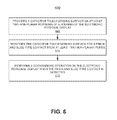
- FIG. 6 illustrates a flow diagram 600 of a method of utilizing a non-screen capacitive touch surface for bookmarking an electronic personal display according to various embodiments.
- the electronic personal display is an electronic reader (eReader). Elements of flow diagram 600 are described below, with reference to elements of one or more of FIGS. 1-5 .
- one embodiment provides a capacitive touch sensing surface on at least two non-planar portions of a housing 110 of the electronic personal display.
- the capacitive touch surface may be, but is not limited to, a grid of conductive lines, a coat of metal, a flexible printed circuit grid and the like.
- the capacitive touch sensing surface may utilize directional sensitivity to provide touch-based gesture capabilities.
- housing 110 of the electronic personal display includes one or more capacitive touch sensing surface(s)
- screen 120 may not necessarily be a capacitive touch sensing surface. Instead, each touch or gesture that would normally be performed on the screen would instead be performed on the housing. In so doing, screen manufacturing costs may be reduced. Additionally, by moving the capacitive touch sensing surface away from the screen, the screen would not be subject to as much touching, swiping, tapping and the like and would provide a cleaner reading surface.
- the screen of the electronic personal display may have a capacitive touch sensing surface.
- one embodiment monitors the capacitive touch sensing surface for a pinch and slide type contact from at least two non-planar points.
- the non-planar points may be generally orthogonal points such as front surface 111 and side surface 113 / 114 or side surface 113 / 114 and rear surface 115 , or generally opposite points such as, front surface 111 and rear surface 115 or left surface 114 and right surface 113 .
- no hard buttons are required for the electronic personal display. That is, there is no need for a hard button on eReader 100 since the capacitive touch sensing surface of the housing 110 is monitored for pinch and slide type gestures. In so doing, a greater robustness with regard to dust, fluid contaminants, sand and the like can be achieved. In other words, by removing the hard buttons there is there are fewer openings through which sand, debris or water can enter the device. Moreover, robustness of the electronic personal display is enhanced since there is no hard button to get gummed up, stuck, spilled on, broken, dropped, dirty, dusty and the like. In an embodiment where no power-up hard button is included, on off switch 130 of FIGS. 1A , 1 B, and 3 is replaced by a smooth surface of housing 110 and a touch sensing surface is used to perform the functions of on/off switch 130 .
- one embodiment performs an operation on the electronic personal display when the pinch and slide type contact is detected.
- the location of the pinch and slide type contact may also be utilized to determine the type of bookmarking operation to be performed.
- the location of the pinch and slide type contact may be, but is not limited to, a top corner, a top edge, a side, a bottom corner, a bottom edge or the like.
- the bookmarking operation may be, but is not limited to, adding a bookmark, removing a bookmark and invocation of a bookmark.
- the pinch and slide location and associated bookmarking action may be factory defined or user adjustable.
- the user may correlate a defined contact type with a defined operation to be performed by the electronic personal display.
- the add bookmark command has been defined as overlapping contact occurring on at least two generally oppositely areas.
- the overlapping contact includes a touch on the top right front surface 111 and the top right rear surface 115 (with reference to FIG. 1A ).
- the pinch and slide is similar to the dog-earing that is sometimes performed to mark a page in a printed book.
- the return to last bookmarked location command has been defined as overlapping contact including a touch on the top left front surface 111 and the top left rear surface 115 .
- the gesture is reviewed by monitoring module 510 and the add bookmark command is recognized.
- the add bookmark command is then passed from monitoring module 510 to operation module 530 which performs the add bookmark action 555 .
Landscapes
- Engineering & Computer Science (AREA)
- General Engineering & Computer Science (AREA)
- Theoretical Computer Science (AREA)
- Human Computer Interaction (AREA)
- Physics & Mathematics (AREA)
- General Physics & Mathematics (AREA)
- Position Input By Displaying (AREA)
Abstract
Description
Claims (21)
Priority Applications (1)
| Application Number | Priority Date | Filing Date | Title |
|---|---|---|---|
| US14/015,739 US9019234B2 (en) | 2013-08-30 | 2013-08-30 | Non-screen capacitive touch surface for bookmarking an electronic personal display |
Applications Claiming Priority (1)
| Application Number | Priority Date | Filing Date | Title |
|---|---|---|---|
| US14/015,739 US9019234B2 (en) | 2013-08-30 | 2013-08-30 | Non-screen capacitive touch surface for bookmarking an electronic personal display |
Publications (2)
| Publication Number | Publication Date |
|---|---|
| US20150062055A1 US20150062055A1 (en) | 2015-03-05 |
| US9019234B2 true US9019234B2 (en) | 2015-04-28 |
Family
ID=52582513
Family Applications (1)
| Application Number | Title | Priority Date | Filing Date |
|---|---|---|---|
| US14/015,739 Active 2033-11-06 US9019234B2 (en) | 2013-08-30 | 2013-08-30 | Non-screen capacitive touch surface for bookmarking an electronic personal display |
Country Status (1)
| Country | Link |
|---|---|
| US (1) | US9019234B2 (en) |
Citations (4)
| Publication number | Priority date | Publication date | Assignee | Title |
|---|---|---|---|---|
| US20110209089A1 (en) * | 2010-02-25 | 2011-08-25 | Hinckley Kenneth P | Multi-screen object-hold and page-change gesture |
| US20110209102A1 (en) * | 2010-02-25 | 2011-08-25 | Microsoft Corporation | Multi-screen dual tap gesture |
| US20130169545A1 (en) * | 2011-12-29 | 2013-07-04 | Research In Motion Corporation | Cooperative displays |
| US20130300668A1 (en) * | 2012-01-17 | 2013-11-14 | Microsoft Corporation | Grip-Based Device Adaptations |
-
2013
- 2013-08-30 US US14/015,739 patent/US9019234B2/en active Active
Patent Citations (4)
| Publication number | Priority date | Publication date | Assignee | Title |
|---|---|---|---|---|
| US20110209089A1 (en) * | 2010-02-25 | 2011-08-25 | Hinckley Kenneth P | Multi-screen object-hold and page-change gesture |
| US20110209102A1 (en) * | 2010-02-25 | 2011-08-25 | Microsoft Corporation | Multi-screen dual tap gesture |
| US20130169545A1 (en) * | 2011-12-29 | 2013-07-04 | Research In Motion Corporation | Cooperative displays |
| US20130300668A1 (en) * | 2012-01-17 | 2013-11-14 | Microsoft Corporation | Grip-Based Device Adaptations |
Also Published As
| Publication number | Publication date |
|---|---|
| US20150062055A1 (en) | 2015-03-05 |
Similar Documents
| Publication | Publication Date | Title |
|---|---|---|
| US10296136B2 (en) | Touch-sensitive button with two levels | |
| US10031604B2 (en) | Control method of virtual touchpad and terminal performing the same | |
| TWI514229B (en) | Graphics editing method and electronic device using the same | |
| US20130154999A1 (en) | Multi-Surface Touch Sensor Device With User Action Detection | |
| US10838539B2 (en) | Touch display device, touch driving circuit, and touch sensing method | |
| US20130154955A1 (en) | Multi-Surface Touch Sensor Device With Mode of Operation Selection | |
| KR101317290B1 (en) | Portable electronic device and method of controlling same | |
| KR20140092059A (en) | Method for controlling portable device equipped with flexible display and portable device thereof | |
| US20150091841A1 (en) | Multi-part gesture for operating an electronic personal display | |
| US20150002449A1 (en) | Capacitive touch surface for powering-up an electronic personal display | |
| CN103631518A (en) | Mobile terminal and display control method for the same | |
| EP3343341A1 (en) | Touch input method through edge screen, and electronic device | |
| CN104777957A (en) | Display method and electronic equipment | |
| US10042445B1 (en) | Adaptive display of user interface elements based on proximity sensing | |
| US20150277581A1 (en) | Movement of an electronic personal display to perform a page turning operation | |
| US8947378B2 (en) | Portable electronic apparatus and touch sensing method | |
| US20150062056A1 (en) | 3d gesture recognition for operating an electronic personal display | |
| KR101865300B1 (en) | Method for controlling behavior of character in touch input device | |
| US20150002450A1 (en) | Non-screen capacitive touch surface for operating an electronic personal display | |
| US9761217B2 (en) | Reducing ambient noise distraction with an electronic personal display | |
| US20110119579A1 (en) | Method of turning over three-dimensional graphic object by use of touch sensitive input device | |
| KR20140029096A (en) | Method and terminal for displaying a plurality of pages | |
| US9019234B2 (en) | Non-screen capacitive touch surface for bookmarking an electronic personal display | |
| US20120242616A1 (en) | Information processing apparatus, information processing method, and program | |
| US9785313B2 (en) | Providing a distraction free reading mode with an electronic personal display |
Legal Events
| Date | Code | Title | Description |
|---|---|---|---|
| AS | Assignment |
Owner name: KOBO INCORPORATED, CANADA Free format text: ASSIGNMENT OF ASSIGNORS INTEREST;ASSIGNORS:LEWIS, DAMIAN;SOOD, RYAN;SIGNING DATES FROM 20130829 TO 20130830;REEL/FRAME:031121/0434 |
|
| STCF | Information on status: patent grant |
Free format text: PATENTED CASE |
|
| AS | Assignment |
Owner name: RAKUTEN KOBO INC., CANADA Free format text: CHANGE OF NAME;ASSIGNOR:KOBO INC.;REEL/FRAME:037753/0780 Effective date: 20140610 |
|
| FEPP | Fee payment procedure |
Free format text: MAINTENANCE FEE REMINDER MAILED (ORIGINAL EVENT CODE: REM.); ENTITY STATUS OF PATENT OWNER: LARGE ENTITY |
|
| FEPP | Fee payment procedure |
Free format text: SURCHARGE FOR LATE PAYMENT, LARGE ENTITY (ORIGINAL EVENT CODE: M1554); ENTITY STATUS OF PATENT OWNER: LARGE ENTITY |
|
| MAFP | Maintenance fee payment |
Free format text: PAYMENT OF MAINTENANCE FEE, 4TH YEAR, LARGE ENTITY (ORIGINAL EVENT CODE: M1551); ENTITY STATUS OF PATENT OWNER: LARGE ENTITY Year of fee payment: 4 |
|
| MAFP | Maintenance fee payment |
Free format text: PAYMENT OF MAINTENANCE FEE, 8TH YEAR, LARGE ENTITY (ORIGINAL EVENT CODE: M1552); ENTITY STATUS OF PATENT OWNER: LARGE ENTITY Year of fee payment: 8 |