US9014777B2 - Detachable biological signal measuring pad and biological signal measuring apparatus using the same - Google Patents

Detachable biological signal measuring pad and biological signal measuring apparatus using the same Download PDF

Info

Publication number
US9014777B2
US9014777B2 US13/810,094 US201113810094A US9014777B2 US 9014777 B2 US9014777 B2 US 9014777B2 US 201113810094 A US201113810094 A US 201113810094A US 9014777 B2 US9014777 B2 US 9014777B2
Authority
US
United States
Prior art keywords
pad
module chip
biological signal
electrode
signal measuring
Prior art date
Legal status (The legal status is an assumption and is not a legal conclusion. Google has not performed a legal analysis and makes no representation as to the accuracy of the status listed.)
Expired - Fee Related, expires
Application number
US13/810,094
Other versions
US20130116534A1 (en
Inventor
Sung Hun Woo
Current Assignee (The listed assignees may be inaccurate. Google has not performed a legal analysis and makes no representation or warranty as to the accuracy of the list.)
UMEDIX CORP Ltd
Original Assignee
UMEDIX CORP Ltd
Priority date (The priority date is an assumption and is not a legal conclusion. Google has not performed a legal analysis and makes no representation as to the accuracy of the date listed.)
Filing date
Publication date
Priority claimed from KR1020100071180A external-priority patent/KR101198377B1/en
Priority claimed from KR1020100071181A external-priority patent/KR101094198B1/en
Application filed by UMEDIX CORP Ltd filed Critical UMEDIX CORP Ltd
Assigned to UMEDIX CORPORATION LIMITED reassignment UMEDIX CORPORATION LIMITED ASSIGNMENT OF ASSIGNORS INTEREST (SEE DOCUMENT FOR DETAILS). Assignors: WOO, SUNG HUN
Publication of US20130116534A1 publication Critical patent/US20130116534A1/en
Application granted granted Critical
Publication of US9014777B2 publication Critical patent/US9014777B2/en
Expired - Fee Related legal-status Critical Current
Adjusted expiration legal-status Critical

Links

Images

Classifications

    • AHUMAN NECESSITIES
    • A61MEDICAL OR VETERINARY SCIENCE; HYGIENE
    • A61BDIAGNOSIS; SURGERY; IDENTIFICATION
    • A61B5/00Measuring for diagnostic purposes; Identification of persons
    • A61B5/68Arrangements of detecting, measuring or recording means, e.g. sensors, in relation to patient
    • A61B5/6801Arrangements of detecting, measuring or recording means, e.g. sensors, in relation to patient specially adapted to be attached to or worn on the body surface
    • A61B5/683Means for maintaining contact with the body
    • A61B5/6832Means for maintaining contact with the body using adhesives
    • A61B5/6833Adhesive patches
    • AHUMAN NECESSITIES
    • A61MEDICAL OR VETERINARY SCIENCE; HYGIENE
    • A61BDIAGNOSIS; SURGERY; IDENTIFICATION
    • A61B5/00Measuring for diagnostic purposes; Identification of persons
    • A61B5/0002Remote monitoring of patients using telemetry, e.g. transmission of vital signals via a communication network
    • A61B5/0015Remote monitoring of patients using telemetry, e.g. transmission of vital signals via a communication network characterised by features of the telemetry system
    • A61B5/0022Monitoring a patient using a global network, e.g. telephone networks, internet
    • AHUMAN NECESSITIES
    • A61MEDICAL OR VETERINARY SCIENCE; HYGIENE
    • A61BDIAGNOSIS; SURGERY; IDENTIFICATION
    • A61B5/00Measuring for diagnostic purposes; Identification of persons
    • A61B5/01Measuring temperature of body parts ; Diagnostic temperature sensing, e.g. for malignant or inflamed tissue
    • AHUMAN NECESSITIES
    • A61MEDICAL OR VETERINARY SCIENCE; HYGIENE
    • A61BDIAGNOSIS; SURGERY; IDENTIFICATION
    • A61B5/00Measuring for diagnostic purposes; Identification of persons
    • A61B5/02Detecting, measuring or recording pulse, heart rate, blood pressure or blood flow; Combined pulse/heart-rate/blood pressure determination; Evaluating a cardiovascular condition not otherwise provided for, e.g. using combinations of techniques provided for in this group with electrocardiography or electroauscultation; Heart catheters for measuring blood pressure
    • A61B5/0205Simultaneously evaluating both cardiovascular conditions and different types of body conditions, e.g. heart and respiratory condition
    • A61B5/02055Simultaneously evaluating both cardiovascular condition and temperature
    • AHUMAN NECESSITIES
    • A61MEDICAL OR VETERINARY SCIENCE; HYGIENE
    • A61BDIAGNOSIS; SURGERY; IDENTIFICATION
    • A61B5/00Measuring for diagnostic purposes; Identification of persons
    • A61B5/02Detecting, measuring or recording pulse, heart rate, blood pressure or blood flow; Combined pulse/heart-rate/blood pressure determination; Evaluating a cardiovascular condition not otherwise provided for, e.g. using combinations of techniques provided for in this group with electrocardiography or electroauscultation; Heart catheters for measuring blood pressure
    • A61B5/024Detecting, measuring or recording pulse rate or heart rate
    • A61B5/02438Detecting, measuring or recording pulse rate or heart rate with portable devices, e.g. worn by the patient
    • AHUMAN NECESSITIES
    • A61MEDICAL OR VETERINARY SCIENCE; HYGIENE
    • A61BDIAGNOSIS; SURGERY; IDENTIFICATION
    • A61B5/00Measuring for diagnostic purposes; Identification of persons
    • A61B5/02Detecting, measuring or recording pulse, heart rate, blood pressure or blood flow; Combined pulse/heart-rate/blood pressure determination; Evaluating a cardiovascular condition not otherwise provided for, e.g. using combinations of techniques provided for in this group with electrocardiography or electroauscultation; Heart catheters for measuring blood pressure
    • A61B5/024Detecting, measuring or recording pulse rate or heart rate
    • A61B5/0245Detecting, measuring or recording pulse rate or heart rate by using sensing means generating electric signals, i.e. ECG signals
    • A61B5/04
    • A61B5/04087
    • A61B5/0478
    • A61B5/0492
    • AHUMAN NECESSITIES
    • A61MEDICAL OR VETERINARY SCIENCE; HYGIENE
    • A61BDIAGNOSIS; SURGERY; IDENTIFICATION
    • A61B5/00Measuring for diagnostic purposes; Identification of persons
    • A61B5/145Measuring characteristics of blood in vivo, e.g. gas concentration, pH value; Measuring characteristics of body fluids or tissues, e.g. interstitial fluid, cerebral tissue
    • A61B5/14532Measuring characteristics of blood in vivo, e.g. gas concentration, pH value; Measuring characteristics of body fluids or tissues, e.g. interstitial fluid, cerebral tissue for measuring glucose, e.g. by tissue impedance measurement
    • AHUMAN NECESSITIES
    • A61MEDICAL OR VETERINARY SCIENCE; HYGIENE
    • A61BDIAGNOSIS; SURGERY; IDENTIFICATION
    • A61B5/00Measuring for diagnostic purposes; Identification of persons
    • A61B5/24Detecting, measuring or recording bioelectric or biomagnetic signals of the body or parts thereof
    • A61B5/25Bioelectric electrodes therefor
    • A61B5/251Means for maintaining electrode contact with the body
    • A61B5/257Means for maintaining electrode contact with the body using adhesive means, e.g. adhesive pads or tapes
    • A61B5/259Means for maintaining electrode contact with the body using adhesive means, e.g. adhesive pads or tapes using conductive adhesive means, e.g. gels
    • AHUMAN NECESSITIES
    • A61MEDICAL OR VETERINARY SCIENCE; HYGIENE
    • A61BDIAGNOSIS; SURGERY; IDENTIFICATION
    • A61B5/00Measuring for diagnostic purposes; Identification of persons
    • A61B5/24Detecting, measuring or recording bioelectric or biomagnetic signals of the body or parts thereof
    • A61B5/25Bioelectric electrodes therefor
    • A61B5/279Bioelectric electrodes therefor specially adapted for particular uses
    • A61B5/291Bioelectric electrodes therefor specially adapted for particular uses for electroencephalography [EEG]
    • AHUMAN NECESSITIES
    • A61MEDICAL OR VETERINARY SCIENCE; HYGIENE
    • A61BDIAGNOSIS; SURGERY; IDENTIFICATION
    • A61B5/00Measuring for diagnostic purposes; Identification of persons
    • A61B5/24Detecting, measuring or recording bioelectric or biomagnetic signals of the body or parts thereof
    • A61B5/25Bioelectric electrodes therefor
    • A61B5/279Bioelectric electrodes therefor specially adapted for particular uses
    • A61B5/296Bioelectric electrodes therefor specially adapted for particular uses for electromyography [EMG]
    • AHUMAN NECESSITIES
    • A61MEDICAL OR VETERINARY SCIENCE; HYGIENE
    • A61BDIAGNOSIS; SURGERY; IDENTIFICATION
    • A61B5/00Measuring for diagnostic purposes; Identification of persons
    • A61B5/72Signal processing specially adapted for physiological signals or for diagnostic purposes
    • A61B5/7203Signal processing specially adapted for physiological signals or for diagnostic purposes for noise prevention, reduction or removal
    • AHUMAN NECESSITIES
    • A61MEDICAL OR VETERINARY SCIENCE; HYGIENE
    • A61BDIAGNOSIS; SURGERY; IDENTIFICATION
    • A61B5/00Measuring for diagnostic purposes; Identification of persons
    • A61B5/72Signal processing specially adapted for physiological signals or for diagnostic purposes
    • A61B5/7225Details of analog processing, e.g. isolation amplifier, gain or sensitivity adjustment, filtering, baseline or drift compensation

Definitions

  • the present invention relates to a detachable biological signal measuring pad and a biological signal measuring apparatus using the same, and more particularly, to a detachable biological signal measuring pad that may greatly improve portability and ease of use, and a biological signal measuring apparatus using the same.
  • the present invention is directed to a detachable biological signal measuring pad which may be more easily portable and improve utilization of measured results, and a biological signal measuring apparatus using the same.
  • a detachable biological signal measuring pad including: an adhesive pad main body detachably adhered to a body; a biological signal detecting electrode provided on an adhesive surface of the main body adhered to the body; and a module chip including a memory card mounted on the main body so as to be connected with the electrode and storing biological signals measured in the electrode, and provided on a surface opposite to the adhesive surface.
  • a biological signal measuring apparatus including: a detachable biological signal measuring pad including an adhesive pad main body detachably adhered to a body, a biological signal detecting electrode provided on an adhesive surface of the main body adhered to the body, and a module chip including a memory card mounted on the main body so as to be connected with the electrode and storing biological signals measured in the electrode; and an analysis device receiving and analyzing the biological signals stored in the memory card.
  • a detachable biological signal measuring pad including: a pad main body detachably adhered to a body; a biological signal detecting electrode provided on an adhesive surface of the main body adhered to the body; a card module chip including a memory card for storing the biological signals measured in the electrode and a power supply unit for supplying power mounted therein, and provided on a surface opposite to the adhesive surface so as to be physically connected with the electrode; a connecting pad provided between the electrode of the main body and the card module chip, and including a connecting means for physically connecting the module chip and the electrode, the connecting means including a connecting pin protruding from the card module chip and a plug groove connected with the electrode and formed on the connecting pad so as to receive the connecting pin; and a sensing module provided on the connecting pad so as to be electrically connected with the plug groove of the connecting means, and including a sensing unit for amplifying the biological signals from the electrode transmitted through the plug groove and removing noise.
  • a biological signal measuring apparatus including: a system-on-chip biological signal measuring pad including a card module chip in which a memory card is mounted; and an analysis device receiving and analyzing the biological signals stored in the memory card, wherein the system-on-chip biological signal measuring pad includes an adhesive pad main body detachably adhered to a body, a biological signal detecting electrode provided on an adhesive surface of the main body adhered to the body, a card module chip including a memory card for storing the biological signals measured in the electrode and a power supply unit for supplying power mounted therein, and provided on a surface opposite to the adhesive surface so as to be physically connected with the electrode, and a connecting pad provided between the electrode of the main body and the card module chip, and including a connecting means for physically connecting the card module chip and the electrode and a sensing module chip provided on the connecting pad so as to be electrically connected with a plug groove, wherein the connecting means includes a connecting pin protruding from the card module chip and the plug groove formed on
  • the detachable biological signal measuring pad may be easily carried by a user, and therefore the health status of the user may be conveniently measured anytime and anywhere.
  • the detachable biological signal measuring pad may be communicated with the analysis device by loading the detachable memory card in the analysis device or using wireless communication, and therefore the measured results are rapidly utilized. As a result, rapid measuring and utilization of the biological signals are achieved to thereby realize a healthy society.
  • the detachable biological signal measuring pad the sensing module chip and the card module chip are separately implemented, and therefore the detachable biological signal measuring pad may be attached and detached according to a variety of applications.
  • the size of the detachable biological signal measuring pad may be further reduced, and power consumption may be further reduced.
  • the detachable biological signal measuring pad may be replaced in accordance with a variety of biological signals such as ECG waveforms, EEG waveforms, EMG waveforms, pulse waveforms, body temperature, blood sugar, and the like, and simultaneously measure the above-described biological signals.
  • FIG. 1 is a drawing showing a configuration of a biological signal measuring apparatus including a detachable biological signal measuring pad according to a first embodiment of the present invention
  • FIG. 2 is an exploded perspective view showing the detachable biological signal measuring pad shown in FIG. 1 ;
  • FIG. 3 is a cross-sectional view showing a coupling state of FIG. 2 ;
  • FIG. 4 is a drawing showing an internal configuration of a module chip of the detachable biological signal measuring pad shown in FIG. 2 ;
  • FIG. 5 is a drawing showing a configuration of a biological signal measuring apparatus including a detachable biological signal measuring pad according to a second embodiment of the present invention
  • FIG. 6 is an exploded perspective view showing the detachable biological signal measuring pad shown in FIG. 5 ;
  • FIGS. 7 and 8 are cross-sectional views showing a coupling state of FIG. 6 ;
  • FIG. 9 is a drawing showing an internal configuration of a card module chip of the detachable biological signal measuring pad shown in FIG. 6 ;
  • FIG. 10 is a drawing showing an internal configuration of a sensing module chip of the detachable biological signal measuring pad shown in FIG. 6 .
  • FIG. 1 is a drawing schematically showing a system configuration of a biological signal measuring apparatus according to a first embodiment of the present invention.
  • the biological signal measuring apparatus according to the present invention includes a detachable biological signal measuring pad 100 that may be attached and detached to and from a user's body such as a wrist 1 , like a band-aid, and an analysis device 10 that receives and analyzes biological signals measured in the measuring pad 100 .
  • biological signals such as a pulse or body temperature may be measured and recorded in a memory card 111 mounted in the pad 100 , the recorded information may be analyzed which is transmitted to a mobile phone 12 or a dedicated terminal 13 such as a computer 11 of a medical institution or a smart phone, and then the analyzed information may be provided to the user as useful information.
  • the measuring pad 100 may be attached to the chest or the head, as necessary, and the measured biological signals encompass electrocardiogram (ECG) waveforms, electro-encephalogram (EEG) waveforms, electromyogram (EMG) waveforms, pulse waveforms, a body temperature, a blood sugar, and the like.
  • ECG electrocardiogram
  • EEG electro-encephalogram
  • EMG electromyogram
  • pulse waveforms a body temperature, a blood sugar, and the like.
  • a user attaches the biological signal measuring pad 100 to an appropriate body region so as to measure biological signals, as necessary, while carrying the biological signal measuring pad 100 like a band-aid, and transmits the measured biological signals to the analysis device 10 to check his/her own health status and required measures.
  • a method of transmitting the biological signals to the analysis device 10 both a method in which the memory card 111 mounted on the measuring pad 100 is pulled and directly inserted into card slots 11 a , 12 a , and 13 a of the analysis device 10 to thereby load measured data, and a method in which the biological signals are transmitted to the communication modules 11 b , 12 b , and 13 b of the analysis device 10 in a wireless manner using a personal area network (PAN), may be used.
  • PAN personal area network
  • FIGS. 2 and 3 are drawings respectively showing an exploded state and a coupling state of a structure of the biological signal measuring pad 100
  • FIG. 4 is a drawing showing an internal structure of the module chip 110 that is a core component.
  • the biological signal measuring pad 100 includes an adhesive pad main body 130 capable of attaching to skin, a module chip 110 in which a memory card 111 and a battery 112 a are detachably inserted through a slot 110 c , and a connecting pad 120 interposed between the pad main body 130 and the module chip 110 .
  • a bottom surface of the pad main body 130 is an adhesive surface attached to skin, and a pair of electrodes 140 for measuring biological signals is mounted on the adhesive surface. That is, when attaching the measuring pad 100 to skin, the pair of electrodes 140 are brought into contact with the skin, and receive biological signals such as a pulse or body temperature as electrical signals. Next, the pair of electrodes 140 are connected with a connecting pin 110 a of the module chip 110 through a connecting means provided in a connecting pad 120 . Accordingly, the biological signals received through the electrode 140 are transmitted to the module chip through the connecting pin 110 a . A process of processing signals in the module chip 110 will be described below with reference to FIG. 4 .
  • a reference numeral 121 indicates a plug groove composed of the connecting means for connecting the electrode 140 and the module chip 110 together with the connecting pin 110 a . That is, the connecting pin 110 a of the module chip 110 is connected to the electrode 140 provided on the pad main body 130 through the plug groove 121 of the connecting pad 120 .
  • adhesive members 110 b and 122 adhered to each other are provided above the connecting pad 120 and below the module chip 110 . Obviously, a binding force through forcible coupling between the connecting pin 110 a and the electrode 140 is maintained, but the adhesive members 110 b and 122 more firmly fix the module chip 110 .
  • the pad main body 130 and the connecting pad 120 are coupled with each other through an adhesive.
  • the module chip 110 includes a sensing unit 114 that amplifies the biological signals from the electrode 140 and removes noise, a microcomputer unit 113 that controls the module chip 110 by processing the biological signals input from the sensing unit 114 and storing the processed biological signals in the memory card 111 , and a power supply unit 112 that supplies power to the module chip 110 .
  • the memory card 111 and the battery 112 a are attached and detached to and from the module chip 110 through the slot 110 c , the battery 112 a inserted into the module chip 110 is mounted in the power supply unit 112 , and the memory card 111 is mounted so as to be connected with the microcomputer unit 113 .
  • the microcomputer unit 113 includes an AD converter 113 a for converting the biological signals received through the sensing unit 114 from analog signals to digital signals, a data memory 113 b for storing the biological signals converted into the digital signals, and a program memory 113 c for storing a program controlling the module chip 110 . Accordingly, the analog biological signals received from the sensing unit 114 in accordance with the program stored in the program memory 113 c are converted into digital signals through the AD converter 113 a , stored in the data memory 113 b , transmitted to the memory card 111 , and then stored in the memory unit 111 a .
  • the memory card 111 includes a memory unit 111 a for storing the measured digital signals, a communication unit 111 c for transmitting the stored biological signals to the outside, and an internal control unit for controlling storage and transmission in accordance with a control of the module chip 110 .
  • the internal control unit 111 b may compress or encrypt data.
  • the communication unit 111 c may include zigbee, Bluetooth, WiFi, or the like, as PAN. Accordingly, the biological signal data stored in the memory unit 111 a may be transmitted by communicating with the communication modules 11 b , 12 b , and 13 b of the analysis device 10 through the communication unit 111 c as described above.
  • the biological signal data may be transmitted in such a manner that the memory card 111 itself is pulled out from the module chip 110 , and then is loaded which is inserted into the card slots 11 a , 12 a , and 13 a of the analysis device 10 .
  • the biological signal measuring apparatus described as above may be utilized as follows.
  • a user attaches the biological signal measuring pad 100 to an appropriate body region when wishing to measure his own health status while carrying the biological signal measuring pad 100 .
  • a case in which a user attaches the pad 100 to his own wrist 1 to measure a pulse waveform is assumed.
  • the memory card 111 for data storage and communication and the battery 112 a that is a power source should be mounted in the module chip 110 .
  • a conductive gel may be attached to the electrode 140 .
  • analog biological signals such as pulse waveforms are measured through the electrode 140 , and the measured analog biological signals are transmitted to the module chip 110 through the connecting pin 110 a connected with the electrode 140 .
  • the analog signals transmitted into the module chip 110 are amplified in the sensing unit 114 , converted into digital signals in the AD converter 113 a , and then stored in the data memory 113 b and the memory unit 111 a of the memory card 111 .
  • data may be transmitted in such a manner that the communication unit 111 c is connected with the communication modules 11 a , 12 a , and 13 a of the analysis device 10 in a wireless manner.
  • a transmission button may be provided on one side of the module chip 110 , and the internal control unit 111 b operates the communication unit 111 c to thereby initiate wireless communication when a corresponding button is pushed by a user.
  • a user pulls the memory card 111 out from the module chip 110 , and directly mounts the memory card 111 in the analysis device 10 to thereby transmit data.
  • the analysis device 10 analyzes the transmitted biological signals, and informs diagnostic results suitable for the analyzed signals.
  • the analysis device 10 informs a corresponding diagnostic result as normal, and when the pulse waveform is in an abnormal range such as bradycardia or pyknocardia, the analysis device 10 informs required measures such as recommending diagnosis of a corresponding health status and consultation with experts, or the like. Then, the user may well manage his health status by appropriately performing corresponding measures.
  • a user may conveniently measure his own health status anytime and anywhere, and communicate with the analysis device by loading the detachable memory card in the analysis device or using wireless communication, and therefore the measured results are rapidly utilized.
  • rapid measuring and utilization of the biological signals are achieved to thereby realize a healthy society.
  • FIG. 5 is a drawing schematically showing a system configuration of a biological signal measuring apparatus according to a second embodiment of the present invention.
  • the biological signal measuring apparatus of the present invention includes a detachable biological signal measuring pad 200 that is detachably adhered to a user's body such as a wrist 1 like a band-aid, and an analysis device 10 that receives and analyzes the biological signals measured in the measuring pad 200 . That is, when the biological signal measuring pad 200 is attached to a user's skin, biological signals such as a pulse or a body temperature are measured and recorded in the memory card 211 mounted in the pad 200 , the recorded information is analyzed which is transmitted to a computer 11 of the medical institution, a mobile phone such as a smart phone, or a dedicated terminal 13 , and then transmitted to the user as useful information.
  • the measuring pad 200 may be attached to the chest or the head, as necessary, and the measured biological signals encompass ECG waveforms, EEG waveforms, EMG waveforms, pulse waveforms, a body temperature, a blood sugar, and the like.
  • a user attaches the biological signal measuring pad 200 to an appropriate body region so as to measure biological signals, as necessary, while carrying the biological signal measuring pad 200 like a band-aid, and transmits the measured biological signals to the analysis device 10 to check his own health status and required measures.
  • both a method in which the memory card 211 mounted on the measuring pad 200 is pulled and directly inserted into card slots 11 a , 12 a , and 13 a of the analysis device 10 to thereby load measured data, and a method in which the biological signals are transmitted to the communication modules 11 b , 12 b , and 13 b of the analysis device 10 in a wireless manner using PAN, may be used.
  • FIG. 6 is a drawing showing an exploded state of a structure of the biological signal measuring pad 200
  • FIGS. 7 and 8 are drawings respectively showing a coupling state of the biological signal measuring pad 200
  • FIGS. 9 and 10 are drawings respectively showing an internal structure of a card module chip 210 and a sensing module 250 which are core components.
  • the biological signal measuring pad 200 includes an adhesive pad main body 230 capable of attaching to skin, a module chip 210 in which a memory card 211 and a battery 212 a are detachably inserted through a slot 210 c , a connecting pad 220 interposed between the adhesive pad main body 230 and the card module chip 210 , and a sensing module 250 provided on the connecting pad 220 .
  • a bottom surface of the pad main body 230 is an adhesive surface attached to skin, and a pair of electrodes 240 for measuring biological signals is mounted on the adhesive surface. That is, when attaching the measuring pad 200 to the skin, the pair of electrodes 240 are brought into contact with the skin, and receive biological signals such as a pulse or a body temperature as electrical signals. Next, the pair of electrodes 240 are physically coupled with a connecting pin 210 a of the module chip 210 through a connecting means provided in a connecting pad 220 . Accordingly, the biological signals received through the electrode 240 are transmitted to the module chip through the connecting pin 210 a .
  • a reference numeral 221 indicates a plug groove constituting the connecting means for connecting the electrode 240 and the module chip 210 together with the connecting pin 210 a . That is, the connecting pin 210 a of the module chip 210 is connected to the electrode 240 provided on the pad main body 230 through the plug grove 221 of the connecting pad 220 . Accordingly, the card module chip 210 and the connecting pad 220 are physically coupled with the electrode 240 . In addition, the plug grooves 221 of the connecting pad 220 are electrically connected with the sensing module 250 provided on the connecting pad 220 through a wire 251 . Accordingly, biological signals received through the electrode 240 are transmitted to the sensing module 250 through the connecting pin 210 a . The pad main body 230 and the connecting pad 220 are coupled with each other using an adhesive. A configuration of the card module chip 210 and a signal processing process in the sensing module chip 250 will be described below with reference to FIGS. 9 and 10 .
  • the connecting pad may further include a signal connection means for electrically connecting the sensing module chip 250 and the card module chip 210 .
  • a reference numeral 223 indicates a signal connection groove constituting the signal connection means for physically connecting to the sensing module 250 and the connecting pad 220 and electrically connecting to the card module chip 210 , together with the signal connection pin 210 b . That is, the signal connection pin 210 b of the card module chip 210 is connected to the sensing module 250 provided on the connecting pad 220 through the signal connection groove 223 of the connecting pad 220 . Accordingly, the card module chip 210 and the sensing module 250 are electrically connected with each other.
  • the card module chip 210 includes a memory card 211 for storing biological signals which are detected from the electrode 240 and amplified in the sensing module 250 , and whose noise is removed, and a power supply unit 212 for supplying power.
  • the memory card 211 and the battery 212 a are detachably inserted in the card module chip 210 through the slot 210 c
  • the battery 212 a inserted in the card module chip 210 is mounted on the power supply unit 212
  • power is supplied to the sensing module 250 through a wire 252 .
  • the memory card 211 receives biological signals from the sensing module 250 .
  • the memory card 211 includes a memory unit 211 a for storing measured digital biological signals, a communication unit 211 c for transmitting the stored biological signals to the outside, and an internal control unit 211 b for controlling storage and transmission in accordance with a control of the card module chip 210 .
  • the internal control unit 211 b may compress or encrypt data.
  • the communication unit 211 c may include zigbee, Bluetooth, WiFi, or the like, as PAN. Accordingly, the biological signal data stored in the memory unit 211 a may be transmitted by communicating with the communication modules 11 b , 12 b , and 13 b of the analysis device 10 through the communication unit 211 c as described above.
  • the biological signal data may be transmitted in such a manner that the memory card 211 itself is pulled out from the module chip 210 , and then is loaded which is inserted into the card slots 11 a , 12 a , and 13 a of the analysis device 10 .
  • the sensing module chip 250 includes a sensing unit 255 for amplifying biological signals from the electrode 240 and removing noise, and a microcomputer unit 254 for controlling the sensing module chip 250 by processing the biological signals input from the sensing unit 255 and storing the processed signals in the memory card 211 of the card module chip 210 .
  • the microcomputer unit 254 includes an AD converter 254 a for converting biological signals received through the sensing unit 255 from analog signals to digital signals, a data memory 254 b for storing the biological signals converted into the digital signals, and a program memory 254 c for storing a program controlling the card module chip 210 .
  • analog biological signals received from the sensing unit 255 in accordance with a program stored in the program memory 254 c are converted into digital signals through the AD converter 254 a , stored in the data memory 254 b , transmitted to the memory card 211 of the card module chip 210 , and then stored in the memory unit 211 a.
  • the biological signal measuring apparatus described as above may be utilized as follows.
  • a user attaches the biological signal measuring pad 200 to an appropriate body region when wishing to measure his own health status while carrying the biological signal measuring pad 200 .
  • a variety of types of pads 200 used in ECG waveforms, EEG waveforms, EMG waveforms, pulse waveforms, a body temperature, a blood sugar, and the like, may be attached according to applications of the pad 200 .
  • a case in which a user attaches the pad 100 to his own wrist 1 to measure a pulse waveform is assumed.
  • the memory card 211 for data storage and communication and the battery 212 a that is a power source should be mounted in the module chip 210 .
  • a conductive gel may be attached to the electrode 240 before attaching the pad 200 to the body.
  • analog biological signals such as pulse waveforms are measured through the electrode 240 , and the measured analog biological signals are transmitted to the sensing module chip 250 through the connecting pin 210 a connected with the electrode 240 .
  • the analog signals transmitted into the module chip 250 are amplified in the sensing unit 255 , converted into digital signals in the AD converter 254 a , and then stored in the data memory 254 b and the memory unit 211 a of the memory card 211 of the card module chip 210 .
  • data may be transmitted in such a manner that the communication unit 211 c is connected with the communication modules 11 a , 12 a , and 13 a of the analysis device 10 in a wireless manner.
  • a transmission button may be provided on one side of the card module chip 210 , and the internal control unit 211 b operates the communication unit 211 c to thereby initiate wireless communication when a corresponding button is pushed by a user.
  • a user pulls the memory card 211 out from the module chip 210 , and directly mounts the memory card 211 in the analysis device 10 to thereby transmit data.
  • the analysis device 10 analyzes the transmitted biological signals, and informs diagnostic results suitable for the analyzed signals.
  • the analysis device 10 informs a corresponding diagnostic result as normal, and when the pulse waveform is in an abnormal range such as bradycardia or pyknocardia, the analysis device 10 informs required measures such as recommending diagnosis of a corresponding health status and consultation with experts, or the like. Then, the user may well manage his health status by appropriately performing corresponding measures.
  • a user may conveniently measure his own health status anytime and anywhere, and communicate with the analysis device by loading the detachable memory card in the analysis device or using wireless communication, and therefore the measured results are rapidly utilized.
  • rapid measuring and utilization of the biological signals are achieved to thereby realize a healthy society.
  • the memory card and the power supply unit may be attached and detached to and from the card module chip, and the sensing unit may be mounted in the sensing module chip.
  • the sensing unit may be manufactured so as to have only its own unique sensing function. Therefore, sizes of the card module chip and the sensing module chip may be reduced, and only one sensing function is driven to thereby reduce power consumption. By the reduction in size and power consumption, the detachable biological signal measuring pad according to the present invention may be more easily carried.
  • the detachable biological signal measuring pad including two electrodes has been described.
  • the present invention may be implemented in the detachable biological signal measuring pad having one or at least three electrodes.
  • Each electrode may be used for different types of measuring biological signals.
  • the connecting means may include at least three wires
  • the electrode may be connected to the sensing module chip without being connected to the card module chip
  • the power supply unit and the memory card of the card module chip may be connected only to the sensing module chip without being connected to the electrode.
  • the module chip may be directly connected to the analysis device to thereby transmit data from the built-in memory to the analysis device.
  • the transducer may be electrically connected to the electrode, and fixed in the pad main body.
  • the transducer may be a blood sugar sensor for transmitting electrical signals corresponding to blood sugar values to the electrode.
  • the blood sugar sensor may include a microneedle array for forming a fine hole in the skin, and a blood sugar analysis unit for forming electrical signals corresponding to a blood sugar value from blood transmitted through the microneedle array.

Abstract

Disclosed is a detachable biological signal measuring pad that may conveniently measure biological signals such as a pulse or body temperature. The biological signal measuring pad includes an adhesive pad main body detachably adhered to a body, a biological signal detecting electrode provided on an adhesive surface of the main body adhered to the body, and a module chip including a memory card mounted on the main body so as to be connected with the electrode and storing biological signals measured in the electrode, and provided on a surface opposite to the adhesive surface.

Description

CROSS REFERENCE TO PRIOR APPLICATIONS
This application is a National Stage Patent Application of PCT International Patent Application No. PCT/KR2011/005437 (filed on Jul. 22, 2011) under 35 U.S.C. §371, which claims priority to Korean Patent Application Nos. 10-2010-0071180 (filed on Jul. 23, 2010) and 10-2010-0071181 (filed on Jul. 23, 2010), which are all hereby incorporated by reference in their entirety.
TECHNICAL FIELD
The present invention relates to a detachable biological signal measuring pad and a biological signal measuring apparatus using the same, and more particularly, to a detachable biological signal measuring pad that may greatly improve portability and ease of use, and a biological signal measuring apparatus using the same.
BACKGROUND ART
With the advent of the well-being age in recent years, concern about health is gradually growing, and especially early identification and management of the health status of individuals has been known as the most important issue to maintain a healthy life. In particular, well monitoring of biological signals from the body such as pulse or body temperature with respect to health care groups such as the elderly or the chronically ill, is to prevent misfortune such as rapid degradation of the quality of life, and therefore the importance of good understanding of one's health status has been further emphasized. However, as society is gradually aging and population of the elderly is increasing, the number of the chronically ill is increasing due to the westernization of eating habits, whereas an environment to identify and manage biological signals associated with the health of the individuals has not been significantly improved. That is, the number of persons of the health care group whose health status needs to be particularly well-managed is increasing, but an environment to frequently measure the health status of each individual is not actually established. Typically, because a person who wishes to identify their health status has to use examination equipment provided from a medical institution, it is difficult to frequently identify his/her health status, and therefore persons of the health care group having severe ups and downs in their health status have low efficiency. In recent years, home inspection equipment capable of measuring biological signals at home such as an electrocardiogram has been released, but is generally too big and heavy to move, and only measured results are obtainable, and therefore, it is difficult for a user to directly determine which action he/she should take from the measured results unless the user goes again to a medical facility to enquire and seek advice. Accordingly, there is a demand for a new type of system for measuring biological signals that may be more easily portable, and improve utilization of measured results.
DISCLOSURE Technical Problem
The present invention is directed to a detachable biological signal measuring pad which may be more easily portable and improve utilization of measured results, and a biological signal measuring apparatus using the same.
Technical Solution
According to an aspect of the present invention, there is provided a detachable biological signal measuring pad, including: an adhesive pad main body detachably adhered to a body; a biological signal detecting electrode provided on an adhesive surface of the main body adhered to the body; and a module chip including a memory card mounted on the main body so as to be connected with the electrode and storing biological signals measured in the electrode, and provided on a surface opposite to the adhesive surface.
According to another aspect of the present invention, there is provided a biological signal measuring apparatus including: a detachable biological signal measuring pad including an adhesive pad main body detachably adhered to a body, a biological signal detecting electrode provided on an adhesive surface of the main body adhered to the body, and a module chip including a memory card mounted on the main body so as to be connected with the electrode and storing biological signals measured in the electrode; and an analysis device receiving and analyzing the biological signals stored in the memory card.
According to still another aspect of the present invention, there is provided a detachable biological signal measuring pad including: a pad main body detachably adhered to a body; a biological signal detecting electrode provided on an adhesive surface of the main body adhered to the body; a card module chip including a memory card for storing the biological signals measured in the electrode and a power supply unit for supplying power mounted therein, and provided on a surface opposite to the adhesive surface so as to be physically connected with the electrode; a connecting pad provided between the electrode of the main body and the card module chip, and including a connecting means for physically connecting the module chip and the electrode, the connecting means including a connecting pin protruding from the card module chip and a plug groove connected with the electrode and formed on the connecting pad so as to receive the connecting pin; and a sensing module provided on the connecting pad so as to be electrically connected with the plug groove of the connecting means, and including a sensing unit for amplifying the biological signals from the electrode transmitted through the plug groove and removing noise.
According to yet another aspect of the present invention, there is provided a biological signal measuring apparatus including: a system-on-chip biological signal measuring pad including a card module chip in which a memory card is mounted; and an analysis device receiving and analyzing the biological signals stored in the memory card, wherein the system-on-chip biological signal measuring pad includes an adhesive pad main body detachably adhered to a body, a biological signal detecting electrode provided on an adhesive surface of the main body adhered to the body, a card module chip including a memory card for storing the biological signals measured in the electrode and a power supply unit for supplying power mounted therein, and provided on a surface opposite to the adhesive surface so as to be physically connected with the electrode, and a connecting pad provided between the electrode of the main body and the card module chip, and including a connecting means for physically connecting the card module chip and the electrode and a sensing module chip provided on the connecting pad so as to be electrically connected with a plug groove, wherein the connecting means includes a connecting pin protruding from the card module chip and the plug groove formed on the connecting pad so as to receive the connecting pin, and wherein the sensing module chip includes a sensing unit for amplifying the biological signals from the electrode transmitted through the plug groove and removing noise.
Advantageous Effects
As described above, according to the embodiments of the present invention, the detachable biological signal measuring pad may be easily carried by a user, and therefore the health status of the user may be conveniently measured anytime and anywhere. In addition, the detachable biological signal measuring pad may be communicated with the analysis device by loading the detachable memory card in the analysis device or using wireless communication, and therefore the measured results are rapidly utilized. As a result, rapid measuring and utilization of the biological signals are achieved to thereby realize a healthy society.
In addition, in the detachable biological signal measuring pad, the sensing module chip and the card module chip are separately implemented, and therefore the detachable biological signal measuring pad may be attached and detached according to a variety of applications. As a result, the size of the detachable biological signal measuring pad may be further reduced, and power consumption may be further reduced. In particular, the detachable biological signal measuring pad may be replaced in accordance with a variety of biological signals such as ECG waveforms, EEG waveforms, EMG waveforms, pulse waveforms, body temperature, blood sugar, and the like, and simultaneously measure the above-described biological signals.
DESCRIPTION OF DRAWINGS
FIG. 1 is a drawing showing a configuration of a biological signal measuring apparatus including a detachable biological signal measuring pad according to a first embodiment of the present invention;
FIG. 2 is an exploded perspective view showing the detachable biological signal measuring pad shown in FIG. 1;
FIG. 3 is a cross-sectional view showing a coupling state of FIG. 2;
FIG. 4 is a drawing showing an internal configuration of a module chip of the detachable biological signal measuring pad shown in FIG. 2;
FIG. 5 is a drawing showing a configuration of a biological signal measuring apparatus including a detachable biological signal measuring pad according to a second embodiment of the present invention;
FIG. 6 is an exploded perspective view showing the detachable biological signal measuring pad shown in FIG. 5;
FIGS. 7 and 8 are cross-sectional views showing a coupling state of FIG. 6;
FIG. 9 is a drawing showing an internal configuration of a card module chip of the detachable biological signal measuring pad shown in FIG. 6; and
FIG. 10 is a drawing showing an internal configuration of a sensing module chip of the detachable biological signal measuring pad shown in FIG. 6.
MODE FOR INVENTION
Exemplary embodiments of the present invention will be described in detail below with reference to the accompanying drawings. While the present invention is shown and described in connection with exemplary embodiments thereof, it will be apparent to those skilled in the art that various modifications can be made without departing from the spirit and scope of the invention.
Hereinafter, preferred embodiments of the present invention will be described in detail with reference to the accompanying drawings.
FIG. 1 is a drawing schematically showing a system configuration of a biological signal measuring apparatus according to a first embodiment of the present invention. As shown in FIG. 1, the biological signal measuring apparatus according to the present invention includes a detachable biological signal measuring pad 100 that may be attached and detached to and from a user's body such as a wrist 1, like a band-aid, and an analysis device 10 that receives and analyzes biological signals measured in the measuring pad 100. That is, when the biological signal measuring pad 100 is attached to a user's skin, biological signals such as a pulse or body temperature may be measured and recorded in a memory card 111 mounted in the pad 100, the recorded information may be analyzed which is transmitted to a mobile phone 12 or a dedicated terminal 13 such as a computer 11 of a medical institution or a smart phone, and then the analyzed information may be provided to the user as useful information. Here, as an example, a case in which the measuring pad 100 is attached to the wrist 1 has been described, but the measuring pad 100 may be attached to the chest or the head, as necessary, and the measured biological signals encompass electrocardiogram (ECG) waveforms, electro-encephalogram (EEG) waveforms, electromyogram (EMG) waveforms, pulse waveforms, a body temperature, a blood sugar, and the like.
Accordingly, a user attaches the biological signal measuring pad 100 to an appropriate body region so as to measure biological signals, as necessary, while carrying the biological signal measuring pad 100 like a band-aid, and transmits the measured biological signals to the analysis device 10 to check his/her own health status and required measures. As a method of transmitting the biological signals to the analysis device 10, both a method in which the memory card 111 mounted on the measuring pad 100 is pulled and directly inserted into card slots 11 a, 12 a, and 13 a of the analysis device 10 to thereby load measured data, and a method in which the biological signals are transmitted to the communication modules 11 b, 12 b, and 13 b of the analysis device 10 in a wireless manner using a personal area network (PAN), may be used.
Hereinafter, the biological signal measuring pad 100 according to an embodiment of the present invention which is configured so as to implement the above-described function will be described in detail. FIGS. 2 and 3 are drawings respectively showing an exploded state and a coupling state of a structure of the biological signal measuring pad 100, and FIG. 4 is a drawing showing an internal structure of the module chip 110 that is a core component.
First, referring to FIGS. 2 and 3, the biological signal measuring pad 100 includes an adhesive pad main body 130 capable of attaching to skin, a module chip 110 in which a memory card 111 and a battery 112 a are detachably inserted through a slot 110 c, and a connecting pad 120 interposed between the pad main body 130 and the module chip 110.
A bottom surface of the pad main body 130 is an adhesive surface attached to skin, and a pair of electrodes 140 for measuring biological signals is mounted on the adhesive surface. That is, when attaching the measuring pad 100 to skin, the pair of electrodes 140 are brought into contact with the skin, and receive biological signals such as a pulse or body temperature as electrical signals. Next, the pair of electrodes 140 are connected with a connecting pin 110 a of the module chip 110 through a connecting means provided in a connecting pad 120. Accordingly, the biological signals received through the electrode 140 are transmitted to the module chip through the connecting pin 110 a. A process of processing signals in the module chip 110 will be described below with reference to FIG. 4. A reference numeral 121 indicates a plug groove composed of the connecting means for connecting the electrode 140 and the module chip 110 together with the connecting pin 110 a. That is, the connecting pin 110 a of the module chip 110 is connected to the electrode 140 provided on the pad main body 130 through the plug groove 121 of the connecting pad 120. Preferably, adhesive members 110 b and 122 adhered to each other are provided above the connecting pad 120 and below the module chip 110. Obviously, a binding force through forcible coupling between the connecting pin 110 a and the electrode 140 is maintained, but the adhesive members 110 b and 122 more firmly fix the module chip 110. The pad main body 130 and the connecting pad 120 are coupled with each other through an adhesive.
Next, an internal configuration of the module chip 110 will be described with reference to FIG. 4.
As shown in FIG. 4, the module chip 110 includes a sensing unit 114 that amplifies the biological signals from the electrode 140 and removes noise, a microcomputer unit 113 that controls the module chip 110 by processing the biological signals input from the sensing unit 114 and storing the processed biological signals in the memory card 111, and a power supply unit 112 that supplies power to the module chip 110. As described in FIG. 2, the memory card 111 and the battery 112 a are attached and detached to and from the module chip 110 through the slot 110 c, the battery 112 a inserted into the module chip 110 is mounted in the power supply unit 112, and the memory card 111 is mounted so as to be connected with the microcomputer unit 113. The microcomputer unit 113 includes an AD converter 113 a for converting the biological signals received through the sensing unit 114 from analog signals to digital signals, a data memory 113 b for storing the biological signals converted into the digital signals, and a program memory 113 c for storing a program controlling the module chip 110. Accordingly, the analog biological signals received from the sensing unit 114 in accordance with the program stored in the program memory 113 c are converted into digital signals through the AD converter 113 a, stored in the data memory 113 b, transmitted to the memory card 111, and then stored in the memory unit 111 a. The memory card 111 includes a memory unit 111 a for storing the measured digital signals, a communication unit 111 c for transmitting the stored biological signals to the outside, and an internal control unit for controlling storage and transmission in accordance with a control of the module chip 110. The internal control unit 111 b may compress or encrypt data. The communication unit 111 c may include zigbee, Bluetooth, WiFi, or the like, as PAN. Accordingly, the biological signal data stored in the memory unit 111 a may be transmitted by communicating with the communication modules 11 b, 12 b, and 13 b of the analysis device 10 through the communication unit 111 c as described above. Alternatively, the biological signal data may be transmitted in such a manner that the memory card 111 itself is pulled out from the module chip 110, and then is loaded which is inserted into the card slots 11 a, 12 a, and 13 a of the analysis device 10.
The biological signal measuring apparatus described as above may be utilized as follows.
As shown in FIG. 1, a user attaches the biological signal measuring pad 100 to an appropriate body region when wishing to measure his own health status while carrying the biological signal measuring pad 100. Here, a case in which a user attaches the pad 100 to his own wrist 1 to measure a pulse waveform is assumed. Obviously, in this instance, the memory card 111 for data storage and communication and the battery 112 a that is a power source, should be mounted in the module chip 110. Before attaching the pad 100 to the body, a conductive gel may be attached to the electrode 140. In this manner, when attaching the pad 100 to the wrist 1, analog biological signals such as pulse waveforms are measured through the electrode 140, and the measured analog biological signals are transmitted to the module chip 110 through the connecting pin 110 a connected with the electrode 140. The analog signals transmitted into the module chip 110 are amplified in the sensing unit 114, converted into digital signals in the AD converter 113 a, and then stored in the data memory 113 b and the memory unit 111 a of the memory card 111. In this state, when the user wishes to check analyzed results by immediately transmitting the measured biological signals to the analysis device 10, data may be transmitted in such a manner that the communication unit 111 c is connected with the communication modules 11 a, 12 a, and 13 a of the analysis device 10 in a wireless manner. Although not shown in the drawings, a transmission button may be provided on one side of the module chip 110, and the internal control unit 111 b operates the communication unit 111 c to thereby initiate wireless communication when a corresponding button is pushed by a user. Alternatively, a user pulls the memory card 111 out from the module chip 110, and directly mounts the memory card 111 in the analysis device 10 to thereby transmit data.
The analysis device 10 analyzes the transmitted biological signals, and informs diagnostic results suitable for the analyzed signals. When the pulse waveform measured by the user is in a normal range, the analysis device 10 informs a corresponding diagnostic result as normal, and when the pulse waveform is in an abnormal range such as bradycardia or pyknocardia, the analysis device 10 informs required measures such as recommending diagnosis of a corresponding health status and consultation with experts, or the like. Then, the user may well manage his health status by appropriately performing corresponding measures.
Therefore, by utilizing the detachable biological signal measuring pad and apparatus, a user may conveniently measure his own health status anytime and anywhere, and communicate with the analysis device by loading the detachable memory card in the analysis device or using wireless communication, and therefore the measured results are rapidly utilized. As a result, rapid measuring and utilization of the biological signals are achieved to thereby realize a healthy society.
FIG. 5 is a drawing schematically showing a system configuration of a biological signal measuring apparatus according to a second embodiment of the present invention.
As shown in FIG. 5, the biological signal measuring apparatus of the present invention includes a detachable biological signal measuring pad 200 that is detachably adhered to a user's body such as a wrist 1 like a band-aid, and an analysis device 10 that receives and analyzes the biological signals measured in the measuring pad 200. That is, when the biological signal measuring pad 200 is attached to a user's skin, biological signals such as a pulse or a body temperature are measured and recorded in the memory card 211 mounted in the pad 200, the recorded information is analyzed which is transmitted to a computer 11 of the medical institution, a mobile phone such as a smart phone, or a dedicated terminal 13, and then transmitted to the user as useful information. Here, as an example, a case in which the measuring pad 200 is attached to the wrist 1 has been described, but the measuring pad 200 may be attached to the chest or the head, as necessary, and the measured biological signals encompass ECG waveforms, EEG waveforms, EMG waveforms, pulse waveforms, a body temperature, a blood sugar, and the like.
Accordingly, a user attaches the biological signal measuring pad 200 to an appropriate body region so as to measure biological signals, as necessary, while carrying the biological signal measuring pad 200 like a band-aid, and transmits the measured biological signals to the analysis device 10 to check his own health status and required measures.
As a method of transmitting the biological signals to the analysis device 10, both a method in which the memory card 211 mounted on the measuring pad 200 is pulled and directly inserted into card slots 11 a, 12 a, and 13 a of the analysis device 10 to thereby load measured data, and a method in which the biological signals are transmitted to the communication modules 11 b, 12 b, and 13 b of the analysis device 10 in a wireless manner using PAN, may be used.
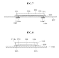
Hereinafter, the biological signal measuring pad 200 according to an embodiment of the present invention which is configured so as to implement the above-described function will be described in detail. FIG. 6 is a drawing showing an exploded state of a structure of the biological signal measuring pad 200, and FIGS. 7 and 8 are drawings respectively showing a coupling state of the biological signal measuring pad 200. FIGS. 9 and 10 are drawings respectively showing an internal structure of a card module chip 210 and a sensing module 250 which are core components.
First, referring to FIGS. 6 to 8, the biological signal measuring pad 200 includes an adhesive pad main body 230 capable of attaching to skin, a module chip 210 in which a memory card 211 and a battery 212 a are detachably inserted through a slot 210 c, a connecting pad 220 interposed between the adhesive pad main body 230 and the card module chip 210, and a sensing module 250 provided on the connecting pad 220.
In the drawings, a bottom surface of the pad main body 230 is an adhesive surface attached to skin, and a pair of electrodes 240 for measuring biological signals is mounted on the adhesive surface. That is, when attaching the measuring pad 200 to the skin, the pair of electrodes 240 are brought into contact with the skin, and receive biological signals such as a pulse or a body temperature as electrical signals. Next, the pair of electrodes 240 are physically coupled with a connecting pin 210 a of the module chip 210 through a connecting means provided in a connecting pad 220. Accordingly, the biological signals received through the electrode 240 are transmitted to the module chip through the connecting pin 210 a. A reference numeral 221 indicates a plug groove constituting the connecting means for connecting the electrode 240 and the module chip 210 together with the connecting pin 210 a. That is, the connecting pin 210 a of the module chip 210 is connected to the electrode 240 provided on the pad main body 230 through the plug grove 221 of the connecting pad 220. Accordingly, the card module chip 210 and the connecting pad 220 are physically coupled with the electrode 240. In addition, the plug grooves 221 of the connecting pad 220 are electrically connected with the sensing module 250 provided on the connecting pad 220 through a wire 251. Accordingly, biological signals received through the electrode 240 are transmitted to the sensing module 250 through the connecting pin 210 a. The pad main body 230 and the connecting pad 220 are coupled with each other using an adhesive. A configuration of the card module chip 210 and a signal processing process in the sensing module chip 250 will be described below with reference to FIGS. 9 and 10.
Preferably, the connecting pad may further include a signal connection means for electrically connecting the sensing module chip 250 and the card module chip 210. A reference numeral 223 indicates a signal connection groove constituting the signal connection means for physically connecting to the sensing module 250 and the connecting pad 220 and electrically connecting to the card module chip 210, together with the signal connection pin 210 b. That is, the signal connection pin 210 b of the card module chip 210 is connected to the sensing module 250 provided on the connecting pad 220 through the signal connection groove 223 of the connecting pad 220. Accordingly, the card module chip 210 and the sensing module 250 are electrically connected with each other.
Next, an internal configuration of the card module chip 210 will be described with reference to FIG. 9. As shown in FIG. 9, the card module chip 210 includes a memory card 211 for storing biological signals which are detected from the electrode 240 and amplified in the sensing module 250, and whose noise is removed, and a power supply unit 212 for supplying power. As described in FIG. 6, the memory card 211 and the battery 212 a are detachably inserted in the card module chip 210 through the slot 210 c, the battery 212 a inserted in the card module chip 210 is mounted on the power supply unit 212, and power is supplied to the sensing module 250 through a wire 252. The memory card 211 receives biological signals from the sensing module 250. The memory card 211 includes a memory unit 211 a for storing measured digital biological signals, a communication unit 211 c for transmitting the stored biological signals to the outside, and an internal control unit 211 b for controlling storage and transmission in accordance with a control of the card module chip 210. The internal control unit 211 b may compress or encrypt data. The communication unit 211 c may include zigbee, Bluetooth, WiFi, or the like, as PAN. Accordingly, the biological signal data stored in the memory unit 211 a may be transmitted by communicating with the communication modules 11 b, 12 b, and 13 b of the analysis device 10 through the communication unit 211 c as described above. Alternatively, the biological signal data may be transmitted in such a manner that the memory card 211 itself is pulled out from the module chip 210, and then is loaded which is inserted into the card slots 11 a, 12 a, and 13 a of the analysis device 10.
Next, an internal configuration of the sensing module chip 250 will be described with reference to FIG. 10. As shown in FIG. 10, the sensing module chip 250 includes a sensing unit 255 for amplifying biological signals from the electrode 240 and removing noise, and a microcomputer unit 254 for controlling the sensing module chip 250 by processing the biological signals input from the sensing unit 255 and storing the processed signals in the memory card 211 of the card module chip 210. The microcomputer unit 254 includes an AD converter 254 a for converting biological signals received through the sensing unit 255 from analog signals to digital signals, a data memory 254 b for storing the biological signals converted into the digital signals, and a program memory 254 c for storing a program controlling the card module chip 210. Accordingly, analog biological signals received from the sensing unit 255 in accordance with a program stored in the program memory 254 c are converted into digital signals through the AD converter 254 a, stored in the data memory 254 b, transmitted to the memory card 211 of the card module chip 210, and then stored in the memory unit 211 a.
The biological signal measuring apparatus described as above may be utilized as follows.
First, as shown in FIG. 5, a user attaches the biological signal measuring pad 200 to an appropriate body region when wishing to measure his own health status while carrying the biological signal measuring pad 200. A variety of types of pads 200 used in ECG waveforms, EEG waveforms, EMG waveforms, pulse waveforms, a body temperature, a blood sugar, and the like, may be attached according to applications of the pad 200. Here, a case in which a user attaches the pad 100 to his own wrist 1 to measure a pulse waveform is assumed. Obviously, in this instance, the memory card 211 for data storage and communication and the battery 212 a that is a power source should be mounted in the module chip 210. Before attaching the pad 200 to the body, a conductive gel may be attached to the electrode 240. In this manner, when attaching the pad 200 to the wrist 1, analog biological signals such as pulse waveforms are measured through the electrode 240, and the measured analog biological signals are transmitted to the sensing module chip 250 through the connecting pin 210 a connected with the electrode 240. The analog signals transmitted into the module chip 250 are amplified in the sensing unit 255, converted into digital signals in the AD converter 254 a, and then stored in the data memory 254 b and the memory unit 211 a of the memory card 211 of the card module chip 210. In this state, when the user wishes to check analyzed results by immediately transmitting the measured biological signals to the analysis device 10, data may be transmitted in such a manner that the communication unit 211 c is connected with the communication modules 11 a, 12 a, and 13 a of the analysis device 10 in a wireless manner. Although not shown in the drawings, a transmission button may be provided on one side of the card module chip 210, and the internal control unit 211 b operates the communication unit 211 c to thereby initiate wireless communication when a corresponding button is pushed by a user. Alternatively, a user pulls the memory card 211 out from the module chip 210, and directly mounts the memory card 211 in the analysis device 10 to thereby transmit data.
The analysis device 10 analyzes the transmitted biological signals, and informs diagnostic results suitable for the analyzed signals. When the pulse waveform measured by the user is in a normal range, the analysis device 10 informs a corresponding diagnostic result as normal, and when the pulse waveform is in an abnormal range such as bradycardia or pyknocardia, the analysis device 10 informs required measures such as recommending diagnosis of a corresponding health status and consultation with experts, or the like. Then, the user may well manage his health status by appropriately performing corresponding measures.
Therefore, by utilizing the detachable biological signal measuring pad and apparatus, a user may conveniently measure his own health status anytime and anywhere, and communicate with the analysis device by loading the detachable memory card in the analysis device or using wireless communication, and therefore the measured results are rapidly utilized. As a result, rapid measuring and utilization of the biological signals are achieved to thereby realize a healthy society.
Meanwhile, in the biological signal measuring pad according to the second embodiment of the present invention, it should be noted that the memory card and the power supply unit may be attached and detached to and from the card module chip, and the sensing unit may be mounted in the sensing module chip. In this manner, when the sensing unit is mounted in separate module chips, a user may select a sensing unit having a sensing function with respect to his suspected disease. That is, the sensing unit may be manufactured so as to have only its own unique sensing function. Therefore, sizes of the card module chip and the sensing module chip may be reduced, and only one sensing function is driven to thereby reduce power consumption. By the reduction in size and power consumption, the detachable biological signal measuring pad according to the present invention may be more easily carried.
The present invention has been described with reference to the embodiments shown in the drawings, but this is merely an example, and it will be apparent to those skilled in the art that various modifications can be made to the above-described exemplary embodiments of the present invention without departing from the spirit or scope of the invention.
For example, in the present specification, the detachable biological signal measuring pad including two electrodes has been described. However, the present invention may be implemented in the detachable biological signal measuring pad having one or at least three electrodes. Each electrode may be used for different types of measuring biological signals.
In addition, in the present specification, an example in which the connecting means and the signal connection means are separately implemented has been described, but an integrated type of the connecting means and the signal connection means may be implemented. For example, the connecting means may include at least three wires, the electrode may be connected to the sensing module chip without being connected to the card module chip, and the power supply unit and the memory card of the card module chip may be connected only to the sensing module chip without being connected to the electrode.
In addition, in the present specification, an example in which the memory card is detachable has been described, but a built-in memory incapable of being attached and detached may be used instead of the memory card. In this case, the module chip may be directly connected to the analysis device to thereby transmit data from the built-in memory to the analysis device.
In addition, in the present specification, an example in which the electrode directly contacts the skin has been described, but a transducer for converting chemical or physical values into electrical signals may be provided between the electrode and the skin. The transducer may be electrically connected to the electrode, and fixed in the pad main body. As an example, the transducer may be a blood sugar sensor for transmitting electrical signals corresponding to blood sugar values to the electrode. In this case, the blood sugar sensor may include a microneedle array for forming a fine hole in the skin, and a blood sugar analysis unit for forming electrical signals corresponding to a blood sugar value from blood transmitted through the microneedle array.
It will be apparent to those skilled in the art that various modifications can be made to the above-described exemplary embodiments of the present invention without departing from the spirit or scope of the invention. Thus, it is intended that the present invention covers all such modifications provided they come within the scope of the appended claims and their equivalents.

Claims (9)

The invention claimed is:
1. A detachable biological signal measuring pad, comprising:
an adhesive pad main body for detachably adhering to a human body;
a biological signal detecting electrode provided on an adhesive surface of the main body and detecting a biological signal generated from the human body;
a module chip including a memory card, and mounted on the main body so as to be connected with the electrode, and storing biological signals measured in the electrode, and provided on a surface of the main body opposite to the adhesive surface, the module chip further including a connecting pin protruding from the module chip; and
a connecting pad provided between the electrode of the main body and the module chip, and having a plug groove through which the connecting pin penetrates the connecting pad to make a direct electrical connection with the electrode,
wherein the connecting pin is directly connected to the electrode, and the module chip is forcibly coupled to the electrode by the connecting pin,
wherein the connecting pad further comprises a first adhesive member disposed on a first side of the connecting pad to couple the connecting pad with the module chip,
wherein the main body and the connecting pad are coupled with each other by an adhesive.
2. The detachable biological signal measuring pad of claim 1, further comprising a second adhesive member provided below the module chip to couple the module chip with the connecting pad.
3. The detachable biological signal measuring pad of claim 1, wherein the memory card is detachably coupled to the module chip.
4. The detachable biological signal measuring pad of claim 3, wherein the memory card includes a memory unit for storing the measured biological signals, a communication unit for transmitting the stored biological signals to the outside, and an internal control unit for controlling storage and transmission in accordance with a control of the module chip.
5. The detachable biological signal measuring pad of claim 1, wherein the module chip includes a sensing unit for amplifying the biological signals from the electrode and removing noise, a microcomputer unit for controlling the module chip by processing the biological signals input from the sensing unit to store the processed biological signals in the memory card, and a power supply unit for supplying power to the module chip.
6. The detachable biological signal measuring pad of claim 5, wherein the microcomputer unit includes an AD converter for converting analog signals input from the sensing unit into digital signals, a data memory for storing biological signals converted into the digital signals, and a program memory for storing a program controlling the module chip.
7. A biological signal measuring apparatus comprising:
a detachable biological signal measuring pad including an adhesive pad main body for detachably adhering to a human body, a biological signal detecting electrode provided on an adhesive surface of the main body and detecting a biological signal generated by the human body, and a module chip including a memory card, and mounted on the main body so as to be connected with the electrode and storing biological signals measured in the electrode; and
an analysis device receiving and analyzing the biological signals stored in the memory card,
wherein the module chip further includes a connecting pin protruding from the module chip,
wherein the detachable biological signal measuring pad further comprises:
a connecting pad provided between the electrode of the main body and the module chip, and having a plug groove through which the connecting pin penetrates the connecting pad to make a direct electrical connection with the electrode,
wherein the connecting pin is directly connected to the electrode, and the module chip is forcibly coupled to the electrode by the connecting pin,
wherein the connecting pad further comprises a first adhesive member disposed on a first side of the connecting pad to couple the connecting pad with the module chip,
wherein the main body and the connecting pad are coupled with each other by an adhesive.
8. The biological signal measuring apparatus of claim 7, wherein the analysis device includes any one of a terminal for the memory card, a mobile phone, and a computer which has a card slot through which the memory card separable from the module chip is able to be inserted.
9. The biological signal measuring apparatus of claim 8, wherein a communication module capable of communicating with the memory card in a wireless manner is provided in the analysis device.
US13/810,094 2010-07-23 2011-07-22 Detachable biological signal measuring pad and biological signal measuring apparatus using the same Expired - Fee Related US9014777B2 (en)

Applications Claiming Priority (5)

Application Number Priority Date Filing Date Title
KR1020100071180A KR101198377B1 (en) 2010-07-23 2010-07-23 Attachable and detachable biological signal measuring pad and biological signal measuring apparatus using the same
KR1020100071181A KR101094198B1 (en) 2010-07-23 2010-07-23 System on chip biological signal measuring pad and biological signal measuring apparatus using the same
KR10-2010-0071180 2010-07-23
KR10-2010-0071181 2010-07-23
PCT/KR2011/005437 WO2012011780A2 (en) 2010-07-23 2011-07-22 Attachable and detachable biological signal measuring pad and biological signal measuring apparatus using the same

Related Parent Applications (1)

Application Number Title Priority Date Filing Date
PCT/KR2011/005437 A-371-Of-International WO2012011780A2 (en) 2010-07-23 2011-07-22 Attachable and detachable biological signal measuring pad and biological signal measuring apparatus using the same

Related Child Applications (1)

Application Number Title Priority Date Filing Date
US14/614,468 Division US9192337B2 (en) 2010-07-23 2015-02-05 Detachable biological signal measuring pad and biological signal measuring apparatus using the same

Publications (2)

Publication Number Publication Date
US20130116534A1 US20130116534A1 (en) 2013-05-09
US9014777B2 true US9014777B2 (en) 2015-04-21

Family

ID=45497325

Family Applications (2)

Application Number Title Priority Date Filing Date
US13/810,094 Expired - Fee Related US9014777B2 (en) 2010-07-23 2011-07-22 Detachable biological signal measuring pad and biological signal measuring apparatus using the same
US14/614,468 Expired - Fee Related US9192337B2 (en) 2010-07-23 2015-02-05 Detachable biological signal measuring pad and biological signal measuring apparatus using the same

Family Applications After (1)

Application Number Title Priority Date Filing Date
US14/614,468 Expired - Fee Related US9192337B2 (en) 2010-07-23 2015-02-05 Detachable biological signal measuring pad and biological signal measuring apparatus using the same

Country Status (3)

Country Link
US (2) US9014777B2 (en)
CN (1) CN103025233B (en)
WO (1) WO2012011780A2 (en)

Cited By (6)

* Cited by examiner, † Cited by third party
Publication number Priority date Publication date Assignee Title
US9955887B2 (en) 2014-10-31 2018-05-01 Irhythm Technologies, Inc. Wearable monitor
US10271754B2 (en) 2013-01-24 2019-04-30 Irhythm Technologies, Inc. Physiological monitoring device
US10405799B2 (en) 2010-05-12 2019-09-10 Irhythm Technologies, Inc. Device features and design elements for long-term adhesion
US11083371B1 (en) 2020-02-12 2021-08-10 Irhythm Technologies, Inc. Methods and systems for processing data via an executable file on a monitor to reduce the dimensionality of the data and encrypting the data being transmitted over the wireless network
US11246523B1 (en) 2020-08-06 2022-02-15 Irhythm Technologies, Inc. Wearable device with conductive traces and insulator
US11350865B2 (en) 2020-08-06 2022-06-07 Irhythm Technologies, Inc. Wearable device with bridge portion

Families Citing this family (44)

* Cited by examiner, † Cited by third party
Publication number Priority date Publication date Assignee Title
CA2973994C (en) 2010-05-21 2019-05-21 Medicomp, Inc. Method of determining optimum electrode vector length between two sensing connectors of a cardiac monitor
US9585584B2 (en) 2010-05-21 2017-03-07 Medicomp, Inc. Physiological signal monitor with retractable wires
US9277864B2 (en) * 2012-05-24 2016-03-08 Vital Connect, Inc. Modular wearable sensor device
US10413251B2 (en) 2012-10-07 2019-09-17 Rhythm Diagnostic Systems, Inc. Wearable cardiac monitor
USD850626S1 (en) * 2013-03-15 2019-06-04 Rhythm Diagnostic Systems, Inc. Health monitoring apparatuses
US10610159B2 (en) 2012-10-07 2020-04-07 Rhythm Diagnostic Systems, Inc. Health monitoring systems and methods
US10244949B2 (en) 2012-10-07 2019-04-02 Rhythm Diagnostic Systems, Inc. Health monitoring systems and methods
US10772522B2 (en) * 2013-03-12 2020-09-15 Vital Connect, Inc. Disposable biometric patch device
US9636017B2 (en) * 2013-03-13 2017-05-02 DePuy Synthes Products, Inc. Telemetric docking station
CN103405228B (en) * 2013-08-21 2015-12-23 中国科学院自动化研究所 A kind of portable cardiac and surface myoelectric measuring device
CN103462601B (en) * 2013-09-24 2016-06-15 深圳先进技术研究院 Electrode for medical service pastes and preparation method thereof
USD744109S1 (en) * 2013-09-25 2015-11-24 Kabushiki Kaisha Toshiba Biomedical signal recorder with a radio function
US20150094559A1 (en) * 2013-09-27 2015-04-02 Covidien Lp Modular physiological sensing patch
CN103462603A (en) * 2013-10-11 2013-12-25 杰升生物科技(上海)有限公司 Attached type electrocardiogram recorder
USD734012S1 (en) * 2014-04-09 2015-07-14 Schawbel Technologies Llc Insole
JP2017520358A (en) * 2014-05-29 2017-07-27 ニューロヴァース・インコーポレイテッド Physiological signal detection and analysis system and apparatus
DE102014008684B4 (en) * 2014-06-13 2020-06-18 Personal Medsystems Gmbh SMART ELECTRODE
WO2016010983A1 (en) * 2014-07-15 2016-01-21 Avery Dennison Corporation Health patch
AU2015296139B2 (en) * 2014-08-01 2019-11-07 Lifelens Technologies, Llc Modular physiologic monitoring systems, kits, and methods
US10575741B2 (en) 2014-08-18 2020-03-03 Samsung Electronics Co., Ltd Wearable biometric information measurement device
TW201611778A (en) * 2014-09-25 2016-04-01 Sigknow Biomedical Corp Ltd Device for long term sensing and recording electrocardiogram
JP6214786B2 (en) * 2014-10-27 2017-10-18 深▲せん▼市光聚通訊技術開発有限公司Shenzhen Waveguider Optical Telecom Technology Inc. Continuous blood glucose collection device and main body
WO2016106647A1 (en) * 2014-12-31 2016-07-07 北京大学深圳研究生院 Affixable body surface electric signal collecting device and mounting method therefor
CN104523252B (en) * 2015-01-04 2018-06-22 深圳市长桑技术有限公司 A kind of mobile health service method and system, mobile terminal
US20170347895A1 (en) 2015-01-04 2017-12-07 Vita-Course Technologies Co.,Ltd System and method for health monitoring
CN204515353U (en) 2015-03-31 2015-07-29 深圳市长桑技术有限公司 A kind of intelligent watch
CN104586422B (en) * 2015-02-13 2017-03-08 清华大学 Many physiological acousticies parameter acquisition system
WO2016154894A1 (en) * 2015-03-31 2016-10-06 深圳迈瑞生物医疗电子股份有限公司 Skin surface temperature probe and body temperature monitor device and surface temperature monitor probe
JP6507254B2 (en) * 2015-09-11 2019-04-24 フクダ電子株式会社 Biological information measuring device
TWI669094B (en) * 2016-02-01 2019-08-21 英屬開曼群島商路提科技股份有限公司 Physiological monitoring device and system
CN106510696A (en) * 2016-12-22 2017-03-22 蓝色传感(北京)科技有限公司 Active noise control digital electrode collecting system and collecting method thereof
US20190059757A1 (en) * 2017-08-31 2019-02-28 Medicomp, Inc. Pendant physiological signal monitor and associated systems and methods
JP6949638B2 (en) * 2017-09-15 2021-10-13 オムロンヘルスケア株式会社 Pulse wave measurement unit and pulse wave measurement device
USD888715S1 (en) * 2018-01-05 2020-06-30 Peloton Interactive, Inc. Cap for an electronic device
USD864396S1 (en) * 2018-07-03 2019-10-22 Simplex Quantum Inc. Electrocardiograph measuring device
USD868974S1 (en) * 2018-07-23 2019-12-03 Alivecor, Inc. Mobile ECG sensor
WO2021041961A1 (en) 2019-08-28 2021-03-04 Rhythm Diagnostic Systems, Inc. Vital signs or health monitoring systems and methods
USD937418S1 (en) * 2019-10-07 2021-11-30 Wahoo Fitness L.L.C. Heart rate monitor
US10878959B1 (en) * 2019-10-25 2020-12-29 Anexa Labs Llc Electronic device for monitoring health metrics
US11402265B2 (en) 2019-11-05 2022-08-02 Texas Instruments Incorporated Apparatus for integrated offset voltage for photodiode current amplifier
USD935617S1 (en) * 2019-12-24 2021-11-09 Etrog Systems Ltd. Belt for a medical monitor
US11263883B2 (en) * 2020-04-16 2022-03-01 Texas Instruments Incorporated System-on-chip for smoke alarm
CN111568611B (en) * 2020-05-27 2023-11-28 北京市春立正达医疗器械股份有限公司 Gap measuring pad, knee joint pressure detection device and use method
US11156965B1 (en) 2020-10-23 2021-10-26 Anexa Labs Llc Latching mechanism for securing two objects

Citations (15)

* Cited by examiner, † Cited by third party
Publication number Priority date Publication date Assignee Title
GB2149918A (en) * 1983-11-03 1985-06-19 John Anderson Sudden infant death syndrome monitor
US5511553A (en) * 1989-02-15 1996-04-30 Segalowitz; Jacob Device-system and method for monitoring multiple physiological parameters (MMPP) continuously and simultaneously
US6117077A (en) * 1999-01-22 2000-09-12 Del Mar Medical Systems, Llc Long-term, ambulatory physiological recorder
US6238338B1 (en) * 1999-07-19 2001-05-29 Altec, Inc. Biosignal monitoring system and method
US6643541B2 (en) * 2001-12-07 2003-11-04 Motorola, Inc Wireless electromyography sensor and system
JP2004529709A (en) 2001-05-03 2004-09-30 テルズート・テクノロジーズ・インコーポレーテッド Medical wireless monitoring device and system
US6856832B1 (en) * 1997-12-25 2005-02-15 Nihon Kohden Corporation Biological signal detection apparatus Holter electrocardiograph and communication system of biological signals
US20050131288A1 (en) * 2003-08-15 2005-06-16 Turner Christopher T. Flexible, patient-worn, integrated, self-contained sensor systems for the acquisition and monitoring of physiologic data
JP2007209428A (en) 2006-02-08 2007-08-23 Matsushita Electric Ind Co Ltd Instrument and system for measuring biological information
US20070208232A1 (en) 2006-03-03 2007-09-06 Physiowave Inc. Physiologic monitoring initialization systems and methods
JP2007296266A (en) 2006-05-08 2007-11-15 Physio Trace Kk Biosensor device
EP2000085A2 (en) 2007-06-07 2008-12-10 Politecnico di Milano Portable electrocardiographic apparatus
CN101534706A (en) 2006-11-01 2009-09-16 韦尔奇阿林公司 Body worn physiological sensor device having a disposable electrode module
US8214009B2 (en) * 2005-10-20 2012-07-03 Samsung Electronics Co., Ltd. Electrode for living body and device for detecting living signal
US8332009B2 (en) * 2007-05-18 2012-12-11 Intelesens Limited Sensors

Patent Citations (16)

* Cited by examiner, † Cited by third party
Publication number Priority date Publication date Assignee Title
GB2149918A (en) * 1983-11-03 1985-06-19 John Anderson Sudden infant death syndrome monitor
US5511553A (en) * 1989-02-15 1996-04-30 Segalowitz; Jacob Device-system and method for monitoring multiple physiological parameters (MMPP) continuously and simultaneously
US6856832B1 (en) * 1997-12-25 2005-02-15 Nihon Kohden Corporation Biological signal detection apparatus Holter electrocardiograph and communication system of biological signals
US6117077A (en) * 1999-01-22 2000-09-12 Del Mar Medical Systems, Llc Long-term, ambulatory physiological recorder
US6238338B1 (en) * 1999-07-19 2001-05-29 Altec, Inc. Biosignal monitoring system and method
US20060155183A1 (en) 2001-05-03 2006-07-13 Kroecker Stephan V Wireless medical monitoring apparatus and system
JP2004529709A (en) 2001-05-03 2004-09-30 テルズート・テクノロジーズ・インコーポレーテッド Medical wireless monitoring device and system
US6643541B2 (en) * 2001-12-07 2003-11-04 Motorola, Inc Wireless electromyography sensor and system
US20050131288A1 (en) * 2003-08-15 2005-06-16 Turner Christopher T. Flexible, patient-worn, integrated, self-contained sensor systems for the acquisition and monitoring of physiologic data
US8214009B2 (en) * 2005-10-20 2012-07-03 Samsung Electronics Co., Ltd. Electrode for living body and device for detecting living signal
JP2007209428A (en) 2006-02-08 2007-08-23 Matsushita Electric Ind Co Ltd Instrument and system for measuring biological information
US20070208232A1 (en) 2006-03-03 2007-09-06 Physiowave Inc. Physiologic monitoring initialization systems and methods
JP2007296266A (en) 2006-05-08 2007-11-15 Physio Trace Kk Biosensor device
CN101534706A (en) 2006-11-01 2009-09-16 韦尔奇阿林公司 Body worn physiological sensor device having a disposable electrode module
US8332009B2 (en) * 2007-05-18 2012-12-11 Intelesens Limited Sensors
EP2000085A2 (en) 2007-06-07 2008-12-10 Politecnico di Milano Portable electrocardiographic apparatus

Cited By (32)

* Cited by examiner, † Cited by third party
Publication number Priority date Publication date Assignee Title
US11141091B2 (en) 2010-05-12 2021-10-12 Irhythm Technologies, Inc. Device features and design elements for long-term adhesion
US10405799B2 (en) 2010-05-12 2019-09-10 Irhythm Technologies, Inc. Device features and design elements for long-term adhesion
US10517500B2 (en) 2010-05-12 2019-12-31 Irhythm Technologies, Inc. Device features and design elements for long-term adhesion
US11051738B2 (en) 2013-01-24 2021-07-06 Irhythm Technologies, Inc. Physiological monitoring device
US11627902B2 (en) 2013-01-24 2023-04-18 Irhythm Technologies, Inc. Physiological monitoring device
US10271754B2 (en) 2013-01-24 2019-04-30 Irhythm Technologies, Inc. Physiological monitoring device
US10555683B2 (en) 2013-01-24 2020-02-11 Irhythm Technologies, Inc. Physiological monitoring device
US11289197B1 (en) 2014-10-31 2022-03-29 Irhythm Technologies, Inc. Wearable monitor
US9955887B2 (en) 2014-10-31 2018-05-01 Irhythm Technologies, Inc. Wearable monitor
US10667712B2 (en) 2014-10-31 2020-06-02 Irhythm Technologies, Inc. Wearable monitor
US11756684B2 (en) 2014-10-31 2023-09-12 Irhythm Technologies, Inc. Wearable monitor
US10299691B2 (en) 2014-10-31 2019-05-28 Irhythm Technologies, Inc. Wearable monitor with arrhythmia burden evaluation
US10098559B2 (en) 2014-10-31 2018-10-16 Irhythm Technologies, Inc. Wearable monitor with arrhythmia burden evaluation
US11605458B2 (en) 2014-10-31 2023-03-14 Irhythm Technologies, Inc Wearable monitor
US10813565B2 (en) 2014-10-31 2020-10-27 Irhythm Technologies, Inc. Wearable monitor
US11253185B2 (en) 2020-02-12 2022-02-22 Irhythm Technologies, Inc. Methods and systems for processing data via an executable file on a monitor to reduce the dimensionality of the data and encrypting the data being transmitted over the wireless network
US11083371B1 (en) 2020-02-12 2021-08-10 Irhythm Technologies, Inc. Methods and systems for processing data via an executable file on a monitor to reduce the dimensionality of the data and encrypting the data being transmitted over the wireless network
US11925469B2 (en) 2020-02-12 2024-03-12 Irhythm Technologies, Inc. Non-invasive cardiac monitor and methods of using recorded cardiac data to infer a physiological characteristic of a patient
US11253186B2 (en) 2020-02-12 2022-02-22 Irhythm Technologies, Inc. Methods and systems for processing data via an executable file on a monitor to reduce the dimensionality of the data and encrypting the data being transmitted over the wireless network
US11246524B2 (en) 2020-02-12 2022-02-15 Irhythm Technologies, Inc. Non-invasive cardiac monitor and methods of using recorded cardiac data to infer a physiological characteristic of a patient
US11375941B2 (en) 2020-02-12 2022-07-05 Irhythm Technologies, Inc. Methods and systems for processing data via an executable file on a monitor to reduce the dimensionality of the data and encrypting the data being transmitted over the wireless network
US11382555B2 (en) 2020-02-12 2022-07-12 Irhythm Technologies, Inc. Non-invasive cardiac monitor and methods of using recorded cardiac data to infer a physiological characteristic of a patient
US11497432B2 (en) 2020-02-12 2022-11-15 Irhythm Technologies, Inc. Methods and systems for processing data via an executable file on a monitor to reduce the dimensionality of the data and encrypting the data being transmitted over the wireless
US11399760B2 (en) 2020-08-06 2022-08-02 Irhythm Technologies, Inc. Wearable device with conductive traces and insulator
US11504041B2 (en) 2020-08-06 2022-11-22 Irhythm Technologies, Inc. Electrical components for physiological monitoring device
US11589792B1 (en) 2020-08-06 2023-02-28 Irhythm Technologies, Inc. Wearable device with bridge portion
US11246523B1 (en) 2020-08-06 2022-02-15 Irhythm Technologies, Inc. Wearable device with conductive traces and insulator
US11350864B2 (en) 2020-08-06 2022-06-07 Irhythm Technologies, Inc. Adhesive physiological monitoring device
US11350865B2 (en) 2020-08-06 2022-06-07 Irhythm Technologies, Inc. Wearable device with bridge portion
US11751789B2 (en) 2020-08-06 2023-09-12 Irhythm Technologies, Inc. Wearable device with conductive traces and insulator
US11806150B2 (en) 2020-08-06 2023-11-07 Irhythm Technologies, Inc. Wearable device with bridge portion
US11337632B2 (en) 2020-08-06 2022-05-24 Irhythm Technologies, Inc. Electrical components for physiological monitoring device

Also Published As

Publication number Publication date
US20130116534A1 (en) 2013-05-09
US20150150506A1 (en) 2015-06-04
WO2012011780A2 (en) 2012-01-26
CN103025233A (en) 2013-04-03
US9192337B2 (en) 2015-11-24
WO2012011780A3 (en) 2012-05-24
CN103025233B (en) 2016-08-17

Similar Documents

Publication Publication Date Title
US9192337B2 (en) Detachable biological signal measuring pad and biological signal measuring apparatus using the same
US11937946B2 (en) Wearable cardiac monitor
US20210212564A1 (en) Head Harness & Wireless EEG Monitoring System
CN105286909B (en) A kind of wearable heart sound and ecg characteristics information collection and monitoring system
CN106913330B (en) Wearable wireless 12-channel electrocardiogram system
KR101706546B1 (en) Personal biosensor accessory attachment
US20110009729A1 (en) Apparatus for measuring physiological signals
US20070027388A1 (en) Patch-type physiological monitoring apparatus, system and network
EP3207871B1 (en) Continuous glucose collecting apparatus
CN101873824B (en) Physiological homecare system
US20150073285A1 (en) Universal ecg electrode module for smartphone
KR101094198B1 (en) System on chip biological signal measuring pad and biological signal measuring apparatus using the same
AU2014290501A1 (en) Medical data acquisition systems and methods for monitoring and diagnosis
TWM452747U (en) Multifunctional physiological monitoring device
WO2015035251A1 (en) Universal ecg electrode module for smartphone
KR101198377B1 (en) Attachable and detachable biological signal measuring pad and biological signal measuring apparatus using the same
Gargiulo et al. Wearable dry sensors with bluetooth connection for use in remote patient monitoring systems
CN104173041A (en) Portable electrocardiogram monitoring system
CN202211690U (en) Rapid electrocardiograph
CN220001797U (en) Digital stethoscope system based on piezoelectric film
US20130109984A1 (en) Biological information measuring band with a rechargeable ability
JP2021528201A (en) Electrode extension assembly for portable ECG and PCG sensor devices
KR20160065465A (en) Integrated Amplifier sensing apparatus for sensing biological signal
WO2015085524A1 (en) Mobile terminal and method for electrocardio-detection
KR20040107884A (en) telemetric device for monitoring autonomic nervous activity

Legal Events

Date Code Title Description
AS Assignment

Owner name: UMEDIX CORPORATION LIMITED, KOREA, REPUBLIC OF

Free format text: ASSIGNMENT OF ASSIGNORS INTEREST;ASSIGNOR:WOO, SUNG HUN;REEL/FRAME:029623/0653

Effective date: 20130103

STCF Information on status: patent grant

Free format text: PATENTED CASE

MAFP Maintenance fee payment

Free format text: PAYMENT OF MAINTENANCE FEE, 4TH YR, SMALL ENTITY (ORIGINAL EVENT CODE: M2551); ENTITY STATUS OF PATENT OWNER: SMALL ENTITY

Year of fee payment: 4

FEPP Fee payment procedure

Free format text: MAINTENANCE FEE REMINDER MAILED (ORIGINAL EVENT CODE: REM.); ENTITY STATUS OF PATENT OWNER: SMALL ENTITY

LAPS Lapse for failure to pay maintenance fees

Free format text: PATENT EXPIRED FOR FAILURE TO PAY MAINTENANCE FEES (ORIGINAL EVENT CODE: EXP.); ENTITY STATUS OF PATENT OWNER: SMALL ENTITY

STCH Information on status: patent discontinuation

Free format text: PATENT EXPIRED DUE TO NONPAYMENT OF MAINTENANCE FEES UNDER 37 CFR 1.362

FP Lapsed due to failure to pay maintenance fee

Effective date: 20230421