RELATED APPLICATION DATA
This application claims priority of U.S. Provisional Application No. 60/910,236 filed on Apr. 5, 2007, which is incorporated herein by reference in its entirety.
FIELD OF THE INVENTION
The present invention relates to an application guide and, more particularly, to a guide tube fixation device for fixing a guide tube in the area of the spinal cord, the use of such a guide tube fixation device for guiding a needle or cannula, and a method for positioning such a guide tube fixation device at a structure, such as a vertebra.
BACKGROUND OF THE INVENTION
Typical vertebral column surgical procedures include vertebral fusion, insertion of implants such as pedicle screws, discography, percutaneous disectomy, or the like. These procedures typically require a large invasive operation that exposes the patient to a high risk of infection, excessive trauma, blood or fluid loss, post operative pain, scaring, and lengthy recovery time.
Some difficulties relating to surgery on the vertebral column include, for example, micro-movement of the vertebral column and of vertebral bodies to each other (which may be a risk for injuring extremely delicate nerve tissue or the spinal cord). Another difficulty encountered in vertebral column surgical procedures is the limited operating room space available to the surgeon. Such space limitations are typically due to relatively large support equipment, such as C-arm X-ray devices, that are in the operating room and used during such procedures. Furthermore, the patient and operating room staff are sometimes exposed to large doses of radiation because these procedures require repeated X-raying and/or fluoroscopy of the surgical site to enable the surgeon to view the position of surgical tools or implants relative to non-visible body parts.
If injuries of the spinal cord are treated, drugs should be delivered as precise and accurate as possible. For example Cordaneurin® from NEURAXO Biopharmaceuticals GmbH can be applied to provoke recovery of sensory and motor function of the spinal nerves, which has been already successfully demonstrated in pre-clinical studies.
U.S. Pat. No. 6,837,892 B2 discloses a miniature surgical robot and a method for using such robot, wherein the miniature surgical robot can be directly attached to a bone of a patient. Two-dimensional X-ray images of the robot on the bone can be registered, for example, with three-dimensional CT images of the bone. This locates the robot precisely on the bone of the patient. The robot then can be directed to pre-operatively determined positions based on a plan devised by the surgeon. The robot then can move to the requested surgical site, and a sleeve can be aligned according to the plan such that the surgeon can insert a surgical tool (e.g., a screwdriver, drill bit, or Kirschner wire) into the sleeve. Via the sleeve, the tool can be aligned with the area so as to conduct the operation percutaneously or in traditional open procedures.
SUMMARY OF THE INVENTION
A guide tube fixation device is provided for attaching or fixing a guide tube at a structure, preferably a body structure or a bone, such as a vertebra, to deliver a substance to a preferably predefined site or location in the area of the spinal cord. The guide tube fixation device includes an attachment element, such as a clamping element or a device having a movable holding element to tense the device against the structure (see, e.g., U.S. Pat. No. 6,719,757 B2 for its teaching regarding moveable spikes). The guide tube fixation device also includes a joint, such as, for example, a ball joint, attached to the attachment element and a guide tube holding device attached to the joint. The guide tube holding device can include, for example, a guide way or hole to hold or guide a guide tube. A cannula or a needle, such as a spinal needle, as for example the PAJUNK 24Gx150 mm, can be inserted into or otherwise guided by the guide tube to the desired site or location. Alternatively, a substance itself can be placed within the guide tube (e.g., without using a needle so that the guide tube itself acts as a needle or cannula). Preferably the guide tube fixation device and particularly the guide tube itself are used for the guidance of one or more thin flexible needles so as to enable precise drug delivery directly to a lesion of the spinal cord, wherein the lesion of the spinal cord can be displayed on a navigation screen superposed to data, such as CT data or MR data, of a patient.
To provide the possibility to perform a navigated drug delivery, preferably one or more navigation elements, such as passive or active markers or a reference star comprising at least three reflective markers, can be attached to the guide tube.
The guide tube fixation device also can be used as described in the above application to guide a needle or cannula, such as a spinal needle or a thin and flexible cannula, to a desired location, such as a lesion of the spinal cord.
A system for guiding medical objects includes a guide tube fixation device as set forth herein and an Instrument Calibration Matrix. The Instrument Calibration Matrix includes navigation elements, such as reflective markers, attached thereto and further comprises calibration points or calibration areas, such as drilled holes having different diameters. A tip of a guide tube can be pointed at or inserted into the calibration points/areas to calibrate the guide tube, which can include one or more attached navigation elements such as a reference star.
A method for positioning a guide tube fixation device at a structure, such as a vertebra or spinous process of a vertebra is also provided. An attachment element, such as a clamping element, can be attached to the structure and the guide tube then can be calibrated, for example, by using the Instrument Calibration Matrix described herein. Alternatively, a pre-calibrated guide tube, which can be identified, for example, by a specific arrangement of markers attached to the guide tube, can be used. Thereafter the calibrated or pre-calibrated guide tube can be connected or attached to the clamping element, and the front or distal end of the guide tube can be navigated (e.g., by using the navigation elements attached to the guide tube) to a desired location, such as a lesion or a point having a predefined distance from the lesion.
Preferably, the body structure containing the area to which the distal end of the guide tube (the navigated portion of the guide tube) is to be placed is examined before attaching the clamping element to the body structure. For example, an MR or a CT scan of the body structure and/or the surrounding area can be used to provide data regarding the shape and size of the structure, and this data can be used for navigating the guide tube and particularly a frontal or distal tip of the guide tube to the desired location.
An injury of the spinal cord can be diagnosed, for example, with MR imaging and can be determined and displayed on a navigation system using, for example, iPlan spine®, which is the trade name for a spinal software planning application sold by BrainLAB AG. In the spinal planning software, the injury can be defined and outlined in MR images. The MR data set can be merged to CT images of the spinal cord and the outlined lesion can be transferred to the CT-scan. The software also may enable direct navigation in MR images. The trajectory for the needle, for example, can be previously defined in the software or can be defined intra-operatively. It is also possible that the MR images are directly registered (Fluoro to MRI registration) with the outlined lesion.
The application guide for the spinal needle can be directly attached to a spinal vertebra or spinous process from the posterior near an identified lesion of the spinal cord. After the registration of the patient's CT data set, as for example a region-based surface matching of the patient's CT data set, dorsal fixation and laminectomy at the region of the spinal lesion, the guide tube of the application guide can be manually placed at the predefined spinal lesion under navigational control and can be fixed at the intended position at the posterior or proximal side or end of the guide tube. Afterwards a spinal needle for drug delivery can be inserted through the guide tube and a drug, such as Cordaneurin®, can be applied to the lesion of the spinal cord over a specified period of time, as for example for about 10 to 15 minutes.
It is preferred that the guide tube, once navigated with its distal tip to the desired location, can be fixed or attached in the desired position to have a defined and fixed relationship with respect to the structure. This can be done, for example, by a joint or joint element that can be adjusted or locked by a screw such that the fixed positional relation between the distal tip of the guiding tube and the structure can be established. Now a needle or cannula can be inserted into the guide tube and can be guided therein so that the tip of the needle (e.g., a spinal needle) exits the distal opening of the guide tube to deliver a substance to a desired location.
The spinal needle can be connected to a holding element that can include an adapter element (or the holding element itself may be the adapter element) so as to enable the needle to be connected to a source of the drug to be delivered. This holding element can limit the insertion of the spinal needle into the guide tube, for example, by abutting at an insertion opening of the guide tube. In the fully inserted position of the spinal needle, the spinal needle can be fixed or attached to the guide tube, for example, by using a fixation element, such as a fixation flap. After the spinal needle has been inserted into and fixed on the guide tube (the distal tip of which was navigated to the desired location), the injection or infusion of a desired substance, such as Cordaneurin®, can be performed.
Thus, the method and apparatus provide an accurate and stable placement and guidance of a specified thin, long and flexible spinal injection needle to a specific area of the lesion. The lesion at the spinal cord can be accurately determined on MR images and can be displayed on a navigation system wherein an MRI data set is superposed on a CT data set of the patient. A software package sold by BrainLAB AG under the trade name VectorVision® spine may be used in conjunction with the method and apparatus.
Since the application guide can be directly placed to the vertebra nearest to the lesion of the spinal cord, any patient movements can be compensated for and it can be assured that the drug is accurately injected to the intended area during a specified period of time. This eliminates the need for any other placement of the thin and flexible needle, which would lead to a less stable and less accurate application drug delivery.
The apparatus and method can be used in connection with planning software to define a distribution pattern of the injected substance(s), such as drugs, cultured cells, stem cells, genetic repair cells, etc.
Although the invention is described with reference to the spinal cord, a substance can be injected or infused to other anatomical regions of the spine and elsewhere, such as for example disc repair with cultured disc cells into the disc.
BRIEF DESCRIPTION OF THE DRAWINGS
The forgoing and other features of the invention are hereinafter discussed with reference to the drawings.
FIG. 1 illustrates an exemplary guide tube fixation device in accordance with the invention.
FIG. 2 is an enlarged view of a guide tube and a marker device.
FIG. 3 is a cross sectional view of an exemplary fixation clamp and ball joint unit in accordance with the invention.
FIG. 4A is a cross sectional view of an exemplary a guide tube and spinal needle.
FIG. 4B is an enlarged view of a portion of the device shown in FIG. 4A.
FIG. 5 illustrates another exemplary guide tube fixation device in accordance with the invention.
FIG. 6 is an exemplary Instrument Calibration Matrix for calibration of the guide tube.
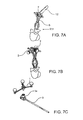
FIGS. 7A-7H illustrate an exemplary method of using the guide tube fixation device in accordance with the invention.
FIG. 8 is a screen shot of an exemplary navigation system used to navigate the guide tube or needle.
DETAILED DESCRIPTION
FIG. 1 shows the elements of an exemplary guide tube fixation device in accordance with the invention. A fixation clamp 6 includes two clamp jaws 6 a and 6 b and a centrical threaded rod to tension the jaws 6 a and 6 b. The clamp 6 also includes a sphere 7 to be used as a ball joint sphere, on which a ball joint unit 2 is attached so as to enable adjustment of a distal tip 3 b of the guide tube 3 and, thus, of a spinal needle 5 guided by the guide tube 3. The guide tube 3 can be inserted through a hole of the ball joint unit 2 and can include a connecting element 3 a for attaching a reference star 1 (e.g., the connecting element 3 a can include an instrument adapter star having for example a StarLink interface). A spinal needle 5 can be guided through the guide tube 3 until the distal tip 5 a of the spinal needle 5 exits the distal or frontal end 3 b of the guide tube 3. A position of the spinal needle 5 can be fixed to the guide tube 3 by means of a fixation flap 4.
FIG. 2 shows an enlarged view of the guide tube 3 having the universal toothed StarLink interface 3 a for attachment of the corresponding instrument adapter star 1. This can be used for manual calibration of the guide tube 3 in combination with the Instrument Calibration Matrix 8 shown in FIG. 6. Alternatively, the guide tube 3 can have a star with different geometry that is rigidly fixed relative to the guide tube 3, so that the guide tube can be used as a pre-calibrated instrument.
FIG. 3 shows in a cross sectional view the fixation clamp 6 and the ball joint unit 2. The fixation clamp 6 has a corresponding sphere 7 for the ball joint interface. The ball joint unit 2 has two corresponding clamps or brackets 2 a and 2 b for fixation to the sphere 7. The ball joint unit 2 enables the guide tube fixation device to be adjusted in multiple three-dimensional degrees of freedom so as to sufficiently and exactly adjust the guide tube 3 to the intended lesion of the spinal cord. After adjustment, the ball joint unit 2 can be rigidly fixed using the fixation device 2 c (e.g., a screw fastener or the like). For proper fixation, a wrench, screw driver, or other tool can be used to manipulate the fixation device 2 c so as to provide sufficient force to fix the ball joint relative to the fixation clamp 6.
Operatively coupled to the fixation device 2 c are a spring 2 d and washer 2 e. The spring and washer can facilitate attachment of the ball joint unit 2 to the sphere 7. For example, the spring 2 d exerts a force on the brackets 2 a and 2 b, which in turn exert a force on the sphere 7. Thus, even though the fixation device 2 c may not create sufficient force to prevent movement of the ball joint unit 2 relative to the sphere 7 (or possible insufficient force to hold the ball joint unit to the sphere), the spring 2 d creates a predetermined force that at least maintains the brackets 2 a and 2 b in contact with the sphere 7. This predetermined force prevents or minimizes the likelihood that the ball joint unit 2 will detach from the sphere 7 before the fixation device 2 c can provide significant holding force. In general, various principles can be feasible for the ball joint design.
The guide tube 3 can be inserted into an opening 2 f of the ball joint unit 2 and fixed in place via clamp 2 g. This enables the position of the guide tube to be fixed relative to the ball joint unit 2.
FIG. 4A shows in a cross sectional view the guide tube 3 and the spinal needle 5, wherein the detail X is shown in an enlarged view in FIG. 4B. After navigated adjustment, the guide tube 3 can be fixated using the fixation device 2 c of the ball joint unit 2. However, other fixation principles are also possible.
The length and the inner core diameter of the guide tube 3 can be exactly aligned for use in combination with a specified spinal needle, such as the PAJUNK 24Gx150 mm. The spinal needle 5 is thereafter inserted into the guide tube 3 until the end stop 3 c prevents further inward movement. Due to the aligned length, it is guaranteed that the tip 5 a of the spinal needle 5 extends out of the guide tube 5 by a predefined length (e.g., 12 mm) at the tip 3 b of the guide tube 3. This length is estimated to provide and achieve a sufficient penetration depth for injection into the lesion as well as to enable sufficient stability during use with less bending of the thin needle tip.
The spinal needle 5 is precisely guided within the core hole 3 d of the guide tube 3, which has a diameter that is within a predetermined tolerance of the spinal needle diameter. For secure fixation of the spinal needle 5 after insertion into the guide tube 3, the guide tube 3 includes slot 3 e for use with the fixation flap 4. The fixation flap 4 can be inserted into the slot 3 e so as to interface with the spinal needle 5 and prevent the needle 5 from being pushed backwards during the application and drug delivery. It is noted that the tip 3 b of the guide tube 3 can have rounded edges so as to minimize the likelihood of injury to the dura or outer surfaces of the spinal cord if accidentally touched during the navigated placement.
FIG. 5 shows another exemplary guide tube fixation device in accordance with the invention. In the embodiment of FIG. 5, the application guide is rigidly fixated to a Schanz-screw or a pedicle screw 10, which is inserted into the pedicle and used for the spinal stabilisation. The shown 1-pin fixation principle is described in U.S. Pat. No. 6,719,757, which is hereby incorporated by reference in its entirety.
Before starting the drug injection, a spinal fixation at the area of the spinal lesion can be performed using standard spinal implant systems, such as polyaxial pedicle screws and rods. Thus, it is also possible to rigidly attach the application guide to a single rod or as a “bridge-design” clamping to opposing rods attached to the structure, such as the vertebra.
FIG. 6 shows an embodiment of an Instrument Calibration Matrix 8 comprising three reflective marker spheres 8 a-8 c attached thereto. Holes or bores 8 d of respective different diameters are provided in the Instrument Calibration Matrix 8, wherein the frontal or distal tip 3 b of the guide tube 3 can be inserted into the bores 8 d to calibrate the guide tube 3 (which has the reference star 1 attached thereto).
FIGS. 7A to 7H show an exemplary method for positioning a guide tube fixation device at a structure (e.g., spinous process of a vertebra) in accordance with the invention. FIG. 8 is a screen shot of an exemplary navigation system that can be used to navigate the guide tube 3 and/or needle 5.
If, for example, there is a spinal fracture at T10, a navigated or standard dorsal fixation with a spine reference X-clamp attached to T9 or T11 can be performed. The spine reference clamp can be attached preferably to a level closer to the camera, for example T11, and a registration can be performed, preferably a region based surface matching of T10. Afterwards, a Laminectomy can be done at T10. The lesion or injury of the spinal cord at T10, for example, can be displayed on an image output device. Further, and if desired, the lesion or injury can be outlined using a software application and displayed as an overlaid structure on the CT-data used in the Navigation System.
The application guide clamp can be tightly fixed on the spinous process of opposing vertebra T9 or T11 via the spine reference X-clamp, wherein a tool 12 can be used to establish sufficient holding force at the X-clamp. Afterwards, the ball joint connector 2 can be attached to the sphere 7 at the clamp, as shown in FIG. 7B. The star link adapter array 1 can be attached to the guide tube adapter 3 a as shown in FIG. 7C, and then manually calibrated with the Instrument Calibration Matrix 8.
A virtual tool tip extension of known pre-defined length (e.g., 12 mm) of the protruding needle tip can be manually adjusted in software so that the real tip position of the later inserted needle 5 can be correctly displayed. Thereafter, the guide tube adapter 3 a can be adjusted with the ball-joint unit 2 under navigational control, so that the extended tip displayed on the navigation screen is in the lesion or injury region of the spinal cord as planned. After the correct position has been found, all fixation screws A and B are properly tightened to fix the position of the guide tube 3 as shown in FIG. 7E. Thereafter, as shown in FIG. 7F, the spinal injection needle 5 can be inserted into the guide tube adapter 3 a.
As shown in FIG. 7G, the needle flap 4 is attached into the slot of the guide tube adapter 3 a in order to properly fixate the spinal injection needle 5. Thereafter, as shown in FIG. 7H, the flexible injection tube for the drug to be delivered is attached to a proximal luer-connector of the spinal injection needle 5 so that the drug can be applied and injected to the lesion or injury at the spinal cord.
Although the invention has been shown and described with respect to a certain preferred embodiment or embodiments, it is obvious that equivalent alterations and modifications will occur to others skilled in the art upon the reading and understanding of this specification and the annexed drawings. In particular regard to the various functions performed by the above described elements (components, assemblies, devices, compositions, etc.), the terms (including a reference to a “means”) used to describe such elements are intended to correspond, unless otherwise indicated, to any element which performs the specified function of the described element (i.e., that is functionally equivalent), even though not structurally equivalent to the disclosed structure which performs the function in the herein illustrated exemplary embodiment or embodiments of the invention. In addition, while a particular feature of the invention may have been described above with respect to only one or more of several illustrated embodiments, such feature may be combined with one or more other features of the other embodiments, as may be desired and advantageous for any given or particular application.