US8992618B2 - Intervertebral prosthesis or disk prosthesis - Google Patents
Intervertebral prosthesis or disk prosthesis Download PDFInfo
- Publication number
- US8992618B2 US8992618B2 US11/587,723 US58772304A US8992618B2 US 8992618 B2 US8992618 B2 US 8992618B2 US 58772304 A US58772304 A US 58772304A US 8992618 B2 US8992618 B2 US 8992618B2
- Authority
- US
- United States
- Prior art keywords
- osteocementum
- implant
- flowable
- intervertebral
- sectional area
- Prior art date
- Legal status (The legal status is an assumption and is not a legal conclusion. Google has not performed a legal analysis and makes no representation as to the accuracy of the status listed.)
- Active, expires
Links
Images


Classifications
-
- A—HUMAN NECESSITIES
- A61—MEDICAL OR VETERINARY SCIENCE; HYGIENE
- A61F—FILTERS IMPLANTABLE INTO BLOOD VESSELS; PROSTHESES; DEVICES PROVIDING PATENCY TO, OR PREVENTING COLLAPSING OF, TUBULAR STRUCTURES OF THE BODY, e.g. STENTS; ORTHOPAEDIC, NURSING OR CONTRACEPTIVE DEVICES; FOMENTATION; TREATMENT OR PROTECTION OF EYES OR EARS; BANDAGES, DRESSINGS OR ABSORBENT PADS; FIRST-AID KITS
- A61F2/00—Filters implantable into blood vessels; Prostheses, i.e. artificial substitutes or replacements for parts of the body; Appliances for connecting them with the body; Devices providing patency to, or preventing collapsing of, tubular structures of the body, e.g. stents
- A61F2/02—Prostheses implantable into the body
- A61F2/30—Joints
- A61F2/44—Joints for the spine, e.g. vertebrae, spinal discs
- A61F2/4455—Joints for the spine, e.g. vertebrae, spinal discs for the fusion of spinal bodies, e.g. intervertebral fusion of adjacent spinal bodies, e.g. fusion cages
- A61F2/447—Joints for the spine, e.g. vertebrae, spinal discs for the fusion of spinal bodies, e.g. intervertebral fusion of adjacent spinal bodies, e.g. fusion cages substantially parallelepipedal, e.g. having a rectangular or trapezoidal cross-section
-
- A—HUMAN NECESSITIES
- A61—MEDICAL OR VETERINARY SCIENCE; HYGIENE
- A61F—FILTERS IMPLANTABLE INTO BLOOD VESSELS; PROSTHESES; DEVICES PROVIDING PATENCY TO, OR PREVENTING COLLAPSING OF, TUBULAR STRUCTURES OF THE BODY, e.g. STENTS; ORTHOPAEDIC, NURSING OR CONTRACEPTIVE DEVICES; FOMENTATION; TREATMENT OR PROTECTION OF EYES OR EARS; BANDAGES, DRESSINGS OR ABSORBENT PADS; FIRST-AID KITS
- A61F2/00—Filters implantable into blood vessels; Prostheses, i.e. artificial substitutes or replacements for parts of the body; Appliances for connecting them with the body; Devices providing patency to, or preventing collapsing of, tubular structures of the body, e.g. stents
- A61F2/02—Prostheses implantable into the body
- A61F2/30—Joints
- A61F2/30767—Special external or bone-contacting surface, e.g. coating for improving bone ingrowth
- A61F2/30771—Special external or bone-contacting surface, e.g. coating for improving bone ingrowth applied in original prostheses, e.g. holes or grooves
-
- A—HUMAN NECESSITIES
- A61—MEDICAL OR VETERINARY SCIENCE; HYGIENE
- A61F—FILTERS IMPLANTABLE INTO BLOOD VESSELS; PROSTHESES; DEVICES PROVIDING PATENCY TO, OR PREVENTING COLLAPSING OF, TUBULAR STRUCTURES OF THE BODY, e.g. STENTS; ORTHOPAEDIC, NURSING OR CONTRACEPTIVE DEVICES; FOMENTATION; TREATMENT OR PROTECTION OF EYES OR EARS; BANDAGES, DRESSINGS OR ABSORBENT PADS; FIRST-AID KITS
- A61F2/00—Filters implantable into blood vessels; Prostheses, i.e. artificial substitutes or replacements for parts of the body; Appliances for connecting them with the body; Devices providing patency to, or preventing collapsing of, tubular structures of the body, e.g. stents
- A61F2/02—Prostheses implantable into the body
- A61F2/30—Joints
- A61F2/44—Joints for the spine, e.g. vertebrae, spinal discs
- A61F2/441—Joints for the spine, e.g. vertebrae, spinal discs made of inflatable pockets or chambers filled with fluid, e.g. with hydrogel
-
- A—HUMAN NECESSITIES
- A61—MEDICAL OR VETERINARY SCIENCE; HYGIENE
- A61F—FILTERS IMPLANTABLE INTO BLOOD VESSELS; PROSTHESES; DEVICES PROVIDING PATENCY TO, OR PREVENTING COLLAPSING OF, TUBULAR STRUCTURES OF THE BODY, e.g. STENTS; ORTHOPAEDIC, NURSING OR CONTRACEPTIVE DEVICES; FOMENTATION; TREATMENT OR PROTECTION OF EYES OR EARS; BANDAGES, DRESSINGS OR ABSORBENT PADS; FIRST-AID KITS
- A61F2/00—Filters implantable into blood vessels; Prostheses, i.e. artificial substitutes or replacements for parts of the body; Appliances for connecting them with the body; Devices providing patency to, or preventing collapsing of, tubular structures of the body, e.g. stents
- A61F2/02—Prostheses implantable into the body
- A61F2/30—Joints
- A61F2/44—Joints for the spine, e.g. vertebrae, spinal discs
- A61F2/442—Intervertebral or spinal discs, e.g. resilient
-
- A—HUMAN NECESSITIES
- A61—MEDICAL OR VETERINARY SCIENCE; HYGIENE
- A61F—FILTERS IMPLANTABLE INTO BLOOD VESSELS; PROSTHESES; DEVICES PROVIDING PATENCY TO, OR PREVENTING COLLAPSING OF, TUBULAR STRUCTURES OF THE BODY, e.g. STENTS; ORTHOPAEDIC, NURSING OR CONTRACEPTIVE DEVICES; FOMENTATION; TREATMENT OR PROTECTION OF EYES OR EARS; BANDAGES, DRESSINGS OR ABSORBENT PADS; FIRST-AID KITS
- A61F2/00—Filters implantable into blood vessels; Prostheses, i.e. artificial substitutes or replacements for parts of the body; Appliances for connecting them with the body; Devices providing patency to, or preventing collapsing of, tubular structures of the body, e.g. stents
- A61F2/02—Prostheses implantable into the body
- A61F2/30—Joints
- A61F2/44—Joints for the spine, e.g. vertebrae, spinal discs
- A61F2/4455—Joints for the spine, e.g. vertebrae, spinal discs for the fusion of spinal bodies, e.g. intervertebral fusion of adjacent spinal bodies, e.g. fusion cages
- A61F2/446—Joints for the spine, e.g. vertebrae, spinal discs for the fusion of spinal bodies, e.g. intervertebral fusion of adjacent spinal bodies, e.g. fusion cages having a circular or elliptical cross-section substantially parallel to the axis of the spine, e.g. cylinders or frustocones
-
- A—HUMAN NECESSITIES
- A61—MEDICAL OR VETERINARY SCIENCE; HYGIENE
- A61F—FILTERS IMPLANTABLE INTO BLOOD VESSELS; PROSTHESES; DEVICES PROVIDING PATENCY TO, OR PREVENTING COLLAPSING OF, TUBULAR STRUCTURES OF THE BODY, e.g. STENTS; ORTHOPAEDIC, NURSING OR CONTRACEPTIVE DEVICES; FOMENTATION; TREATMENT OR PROTECTION OF EYES OR EARS; BANDAGES, DRESSINGS OR ABSORBENT PADS; FIRST-AID KITS
- A61F2/00—Filters implantable into blood vessels; Prostheses, i.e. artificial substitutes or replacements for parts of the body; Appliances for connecting them with the body; Devices providing patency to, or preventing collapsing of, tubular structures of the body, e.g. stents
- A61F2/02—Prostheses implantable into the body
- A61F2/30—Joints
- A61F2/46—Special tools or methods for implanting or extracting artificial joints, accessories, bone grafts or substitutes, or particular adaptations therefor
-
- A—HUMAN NECESSITIES
- A61—MEDICAL OR VETERINARY SCIENCE; HYGIENE
- A61F—FILTERS IMPLANTABLE INTO BLOOD VESSELS; PROSTHESES; DEVICES PROVIDING PATENCY TO, OR PREVENTING COLLAPSING OF, TUBULAR STRUCTURES OF THE BODY, e.g. STENTS; ORTHOPAEDIC, NURSING OR CONTRACEPTIVE DEVICES; FOMENTATION; TREATMENT OR PROTECTION OF EYES OR EARS; BANDAGES, DRESSINGS OR ABSORBENT PADS; FIRST-AID KITS
- A61F2/00—Filters implantable into blood vessels; Prostheses, i.e. artificial substitutes or replacements for parts of the body; Appliances for connecting them with the body; Devices providing patency to, or preventing collapsing of, tubular structures of the body, e.g. stents
- A61F2/02—Prostheses implantable into the body
- A61F2/30—Joints
- A61F2002/30001—Additional features of subject-matter classified in A61F2/28, A61F2/30 and subgroups thereof
- A61F2002/30316—The prosthesis having different structural features at different locations within the same prosthesis; Connections between prosthetic parts; Special structural features of bone or joint prostheses not otherwise provided for
- A61F2002/30535—Special structural features of bone or joint prostheses not otherwise provided for
- A61F2002/30593—Special structural features of bone or joint prostheses not otherwise provided for hollow
-
- A—HUMAN NECESSITIES
- A61—MEDICAL OR VETERINARY SCIENCE; HYGIENE
- A61F—FILTERS IMPLANTABLE INTO BLOOD VESSELS; PROSTHESES; DEVICES PROVIDING PATENCY TO, OR PREVENTING COLLAPSING OF, TUBULAR STRUCTURES OF THE BODY, e.g. STENTS; ORTHOPAEDIC, NURSING OR CONTRACEPTIVE DEVICES; FOMENTATION; TREATMENT OR PROTECTION OF EYES OR EARS; BANDAGES, DRESSINGS OR ABSORBENT PADS; FIRST-AID KITS
- A61F2/00—Filters implantable into blood vessels; Prostheses, i.e. artificial substitutes or replacements for parts of the body; Appliances for connecting them with the body; Devices providing patency to, or preventing collapsing of, tubular structures of the body, e.g. stents
- A61F2/02—Prostheses implantable into the body
- A61F2/30—Joints
- A61F2/30767—Special external or bone-contacting surface, e.g. coating for improving bone ingrowth
- A61F2/30771—Special external or bone-contacting surface, e.g. coating for improving bone ingrowth applied in original prostheses, e.g. holes or grooves
- A61F2002/30772—Apertures or holes, e.g. of circular cross section
- A61F2002/30777—Oblong apertures
-
- A—HUMAN NECESSITIES
- A61—MEDICAL OR VETERINARY SCIENCE; HYGIENE
- A61F—FILTERS IMPLANTABLE INTO BLOOD VESSELS; PROSTHESES; DEVICES PROVIDING PATENCY TO, OR PREVENTING COLLAPSING OF, TUBULAR STRUCTURES OF THE BODY, e.g. STENTS; ORTHOPAEDIC, NURSING OR CONTRACEPTIVE DEVICES; FOMENTATION; TREATMENT OR PROTECTION OF EYES OR EARS; BANDAGES, DRESSINGS OR ABSORBENT PADS; FIRST-AID KITS
- A61F2/00—Filters implantable into blood vessels; Prostheses, i.e. artificial substitutes or replacements for parts of the body; Appliances for connecting them with the body; Devices providing patency to, or preventing collapsing of, tubular structures of the body, e.g. stents
- A61F2/02—Prostheses implantable into the body
- A61F2/30—Joints
- A61F2/30767—Special external or bone-contacting surface, e.g. coating for improving bone ingrowth
- A61F2/30771—Special external or bone-contacting surface, e.g. coating for improving bone ingrowth applied in original prostheses, e.g. holes or grooves
- A61F2002/30772—Apertures or holes, e.g. of circular cross section
- A61F2002/30784—Plurality of holes
- A61F2002/30785—Plurality of holes parallel
-
- A—HUMAN NECESSITIES
- A61—MEDICAL OR VETERINARY SCIENCE; HYGIENE
- A61F—FILTERS IMPLANTABLE INTO BLOOD VESSELS; PROSTHESES; DEVICES PROVIDING PATENCY TO, OR PREVENTING COLLAPSING OF, TUBULAR STRUCTURES OF THE BODY, e.g. STENTS; ORTHOPAEDIC, NURSING OR CONTRACEPTIVE DEVICES; FOMENTATION; TREATMENT OR PROTECTION OF EYES OR EARS; BANDAGES, DRESSINGS OR ABSORBENT PADS; FIRST-AID KITS
- A61F2/00—Filters implantable into blood vessels; Prostheses, i.e. artificial substitutes or replacements for parts of the body; Appliances for connecting them with the body; Devices providing patency to, or preventing collapsing of, tubular structures of the body, e.g. stents
- A61F2/02—Prostheses implantable into the body
- A61F2/30—Joints
- A61F2/30767—Special external or bone-contacting surface, e.g. coating for improving bone ingrowth
- A61F2/30771—Special external or bone-contacting surface, e.g. coating for improving bone ingrowth applied in original prostheses, e.g. holes or grooves
- A61F2002/30772—Apertures or holes, e.g. of circular cross section
- A61F2002/30784—Plurality of holes
- A61F2002/30789—Plurality of holes perpendicular with respect to each other
-
- A—HUMAN NECESSITIES
- A61—MEDICAL OR VETERINARY SCIENCE; HYGIENE
- A61F—FILTERS IMPLANTABLE INTO BLOOD VESSELS; PROSTHESES; DEVICES PROVIDING PATENCY TO, OR PREVENTING COLLAPSING OF, TUBULAR STRUCTURES OF THE BODY, e.g. STENTS; ORTHOPAEDIC, NURSING OR CONTRACEPTIVE DEVICES; FOMENTATION; TREATMENT OR PROTECTION OF EYES OR EARS; BANDAGES, DRESSINGS OR ABSORBENT PADS; FIRST-AID KITS
- A61F2/00—Filters implantable into blood vessels; Prostheses, i.e. artificial substitutes or replacements for parts of the body; Appliances for connecting them with the body; Devices providing patency to, or preventing collapsing of, tubular structures of the body, e.g. stents
- A61F2/02—Prostheses implantable into the body
- A61F2/30—Joints
- A61F2/30767—Special external or bone-contacting surface, e.g. coating for improving bone ingrowth
- A61F2/30771—Special external or bone-contacting surface, e.g. coating for improving bone ingrowth applied in original prostheses, e.g. holes or grooves
- A61F2002/30841—Sharp anchoring protrusions for impaction into the bone, e.g. sharp pins, spikes
-
- A61F2002/4475—
-
- A—HUMAN NECESSITIES
- A61—MEDICAL OR VETERINARY SCIENCE; HYGIENE
- A61F—FILTERS IMPLANTABLE INTO BLOOD VESSELS; PROSTHESES; DEVICES PROVIDING PATENCY TO, OR PREVENTING COLLAPSING OF, TUBULAR STRUCTURES OF THE BODY, e.g. STENTS; ORTHOPAEDIC, NURSING OR CONTRACEPTIVE DEVICES; FOMENTATION; TREATMENT OR PROTECTION OF EYES OR EARS; BANDAGES, DRESSINGS OR ABSORBENT PADS; FIRST-AID KITS
- A61F2/00—Filters implantable into blood vessels; Prostheses, i.e. artificial substitutes or replacements for parts of the body; Appliances for connecting them with the body; Devices providing patency to, or preventing collapsing of, tubular structures of the body, e.g. stents
- A61F2/02—Prostheses implantable into the body
- A61F2/30—Joints
- A61F2/44—Joints for the spine, e.g. vertebrae, spinal discs
- A61F2002/448—Joints for the spine, e.g. vertebrae, spinal discs comprising multiple adjacent spinal implants within the same intervertebral space or within the same vertebra, e.g. comprising two adjacent spinal implants
-
- A—HUMAN NECESSITIES
- A61—MEDICAL OR VETERINARY SCIENCE; HYGIENE
- A61F—FILTERS IMPLANTABLE INTO BLOOD VESSELS; PROSTHESES; DEVICES PROVIDING PATENCY TO, OR PREVENTING COLLAPSING OF, TUBULAR STRUCTURES OF THE BODY, e.g. STENTS; ORTHOPAEDIC, NURSING OR CONTRACEPTIVE DEVICES; FOMENTATION; TREATMENT OR PROTECTION OF EYES OR EARS; BANDAGES, DRESSINGS OR ABSORBENT PADS; FIRST-AID KITS
- A61F2/00—Filters implantable into blood vessels; Prostheses, i.e. artificial substitutes or replacements for parts of the body; Appliances for connecting them with the body; Devices providing patency to, or preventing collapsing of, tubular structures of the body, e.g. stents
- A61F2/02—Prostheses implantable into the body
- A61F2/30—Joints
- A61F2/46—Special tools or methods for implanting or extracting artificial joints, accessories, bone grafts or substitutes, or particular adaptations therefor
- A61F2002/4631—Special tools or methods for implanting or extracting artificial joints, accessories, bone grafts or substitutes, or particular adaptations therefor the prosthesis being specially adapted for being cemented
-
- A—HUMAN NECESSITIES
- A61—MEDICAL OR VETERINARY SCIENCE; HYGIENE
- A61F—FILTERS IMPLANTABLE INTO BLOOD VESSELS; PROSTHESES; DEVICES PROVIDING PATENCY TO, OR PREVENTING COLLAPSING OF, TUBULAR STRUCTURES OF THE BODY, e.g. STENTS; ORTHOPAEDIC, NURSING OR CONTRACEPTIVE DEVICES; FOMENTATION; TREATMENT OR PROTECTION OF EYES OR EARS; BANDAGES, DRESSINGS OR ABSORBENT PADS; FIRST-AID KITS
- A61F2310/00—Prostheses classified in A61F2/28 or A61F2/30 - A61F2/44 being constructed from or coated with a particular material
- A61F2310/00005—The prosthesis being constructed from a particular material
- A61F2310/00353—Bone cement, e.g. polymethylmethacrylate or PMMA
Definitions
- the invention relates to an intervertebral prosthesis or disk prosthesis that has a front side, a rear side, an upper side, a right side and a left side.
- the upper side may be suitable for resting against the baseplate of an intervertebral body and the lower side may be suitable for resting on the baseplate of an intervertebral body.
- the invention may also include a cavity suitable for accommodating a flowable hydraulic osteocementurn. There may he an inlet opening into the cavity and several outlet openings emerging from the front side.
- the intervertebral or disk prosthesis is especially for arthrodesis surgery by means of dorsal access PLIF (posterior lumbar interbody fusion), TLIF (transforaminal lumbar interbody fusion), ELIF (extraforaminal lumbar interbody fusion), ALIF (anterior lumbar interbody fusion) and ACIF (anterior cervical interbody fusion).
- the objective of this surgical technique is the treatment of a degenerated or otherwise diseased intervertebral disk.
- the surgeon looks for access to the intervertebral disk through a centrally placed skin incision. Subsequently, he exposes the rear region of the movement segments, especially the laminae and the pedicle entry points.
- the surgeon aims past the nerve roots and the medullary space in the direction of the discased intervertebral disk.
- intervertebral spaces supplied with the known intervertebral implants, therefore frequently do not attain complete arthrodesis, that is, they end in a pseudoarthrosis.
- the situation is much the same also with cage-like intervertebral implants for the cervical spine, as well as for those, which were inserted through ventral entrances.
- Such intervertebral spaces are not stable mechanically, as would have been expected from a stiffening. The consequences then may be recurring pain with subsequent revision surgery.
- the surgeon uses autologous bone material, which he obtains from the resected parts of the vertebral body or by means of an additional intervention in the crest of the ilium. Since dorsal accesses to the intervertebral disk space are very narrow, the applying of bone material is made difficult. The surgeon is unable to ensure that the whole of the intervertebral space is filled with autologous bone material. There is therefore the danger that empty spaces will result which, on the one hand, permits migration of the implant. On the other hand, the spaces, not filled with autologous bone material, are filled by a soft, fibrous tissue.
- the amount of osteocementum K L , emerging through S L is either larger or smaller than the amount of osteocementum K R emerging through S R ; or the amount of osteocementum K H , emerging through S H , is larger or smaller than the amount of osteocementum K V emerging through S V .
- the outlet openings are dimensioned so that, when flowable osteocementum is supplied through the inlet opening into the cavity, the amount of osteocementum K L emerging through S L is either larger or smaller than the amount of osteocementum K R emerging through S R or the amount of osteocementum K H , emerging through S H , is larger or smaller than the amount of osteocementum K V , emerging through S V .
- the invention permits the intervertebral space to be filled with synthetic bone material (osteocementum) after the cage-like intervertebral prosthesis or disk prosthesis has been placed.
- the implant is secured by the emergence and subsequent curing of the flowable, hydraulic osteocementum. Due to the asymmetric arrangement of the outlet openings in the implant, the osteocementum can be spread selectively.
- the inventive prosthesis furthermore has the advantage that it makes superfluous the additional removal of bone at the crest of the iliac, which can cause long enduring pain.
- the inlet opening is provided in the front side of the prosthesis and the cavity extends from the inlet opening in the direction of the rear side.
- the inlet opening is disposed in the left all right side of the prosthesis and the cavity extends from the inlet opening in the direction of the opposite right or left side.
- the cross section of the cavity decreases at least on a partial section as the distance from the inlet opening increases. Due to the tapering of the cavity, the liquid cement mixture flows more easily through the side openings of the implant.
- the wall of the implant in the opening opposite the injection point has a shearing-off edge, so that the liquid cement mixture is diverted.
- the cavity tapers, at least on a partial section, either in wedge-shaped or conical fashion.
- the upper and lower sides converge in the direction of the front side at least on a partial section.
- the prosthesis is filled at least partially with a cured hydraulic osteocementum, which extends at least partially beyond the outlet opening.
- the implant may consist of two intervertebral prostheses, which are disposed next to one another, the right side of the intervertebral prosthesis disposed on the left being oriented in the direction of the left side of the intervertebral prosthesis disposed on the right.
- the condition S L >S R applies and for the intervertebral prosthesis on the right, the condition S R >S L .
- intervertebral prosthesis may be varied in many ways, for example, by using flat, concave, convex or also spherical side walls.
- Calcium phosphate cements which, after the two components are mixed, may be injected in liquid form into the implant and are subsequently cured hydraulically, are suitable as flowable hydraulic osteocementum.
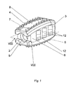
- FIG. 1 shows a perspective view of an inventive, lens-shaped intervertebral implant
- FIG. 2 shows a longitudinal section through the intervertebral implant of FIG. 1 along the central plane VIII-VIII,
- FIG. 3 shows a side view from the right of the intervertebral implant of FIG. 1 ,
- FIG. 4 shows a side view from the left of the intervertebral implant of FIG. 1 .
- FIG. 5 shows a perspective view of an inventive intervertebral prosthesis, which is secured by means of cured osteocementum,
- FIG. 6 shows a plan view of the intervertebral prosthesis of FIG. 5 .
- FIG. 7 shows a perspective view of a variation of the embodiment, using two intervertebral implants, the osteocementum securing the implant in their position relative to one another as well as to prevent migrating apart,
- FIG. 8 shows a plan view of the two intervertebral implants of FIG. 7 .
- FIG. 9 shows a front view of a variation of the embodiments, in which the perforated intervertebral implant has a rectangular cross section and
- FIG. 10 shows a front view of a variation of the embodiment, in which the perforated intervertebral implant has a circular ring-shaped cross section.
- the intervertebral prosthesis 1 shown in FIGS. 1 and 2 , consists of a rectangular hollow body and has a front side 2 , a rear side 3 , an upper side 4 suitable for positioning against the baseplate of a vertebral body, a lower side 5 suitable for positioning against the baseplate of a vertebral body, a right side 6 , a left side 7 , a cavity 8 suitable for accommodating a flowable, hydraulic osteocementum, an inlet opening 9 into the cavity 8 and several outlet openings 10 ; 11 ; 12 ; 13 from the cavity 8 .
- the upper side 4 and the lower side 5 converge toward the front side 2 as well as toward the rear side 3 , so that a lens-like configuration of the intervertebral prosthesis results.
- the cross section of the cavity 8 decreases in the shape of a cone as the distance from the inlet opening 9 increases.
- FIGS. 5 and 6 show how the osteocementum 20 , emerging from the right side 6 and the left side 7 of the intervertebral prosthesis 1 , is distributed. Because the sum S L of the cross sectional areas of the outlet openings 13 emerging on the left side 7 is larger, the amount of osteocementum 20 , emerging on the left side 7 and curing, is also larger than that emerging on the right side 6 and curing.
- FIGS. 7 and 8 show a further embodiment, which consists of two inventive intervertebral prosthesis 1 , which are disposed next to one another.
- the two intervertebral prostheses are positioned in such a manner, that the right side 6 of the intervertebral prosthesis 1 , which is disposed on the left, is oriented in the direction of the left side 7 of the intervertebral prosthesis 1 , which is disposed on the right.
- S L >S R applies
- the reverse applies namely S R >S L .
- FIG. 9 shows a variation of the embodiment of an inventive intervertebral implant 1 , which has a rectangular cross section and from which a larger amount of osteocementum 40 has emerged on the right side than on the left side.
- FIG. 10 shows a further variation of an embodiment of an intervertebral prosthesis 1 , which has a circular cross section and for which the amount of osteocementum 40 emerging on the right side through the outlet openings 12 is larger than that emerging on the left side through outlet openings 13 .
Abstract
Description
Claims (12)
Applications Claiming Priority (1)
| Application Number | Priority Date | Filing Date | Title |
|---|---|---|---|
| PCT/CH2004/000250 WO2005102226A1 (en) | 2004-04-26 | 2004-04-26 | Intervertebral prosthesis or disk prosthesis |
Related Parent Applications (1)
| Application Number | Title | Priority Date | Filing Date |
|---|---|---|---|
| PCT/CH2004/000250 A-371-Of-International WO2005102226A1 (en) | 2004-04-26 | 2004-04-26 | Intervertebral prosthesis or disk prosthesis |
Related Child Applications (1)
| Application Number | Title | Priority Date | Filing Date |
|---|---|---|---|
| US14/638,196 Continuation US9700432B2 (en) | 2004-04-26 | 2015-03-04 | Intervertebral prosthesis or disk prosthesis |
Publications (2)
| Publication Number | Publication Date |
|---|---|
| US20080133015A1 US20080133015A1 (en) | 2008-06-05 |
| US8992618B2 true US8992618B2 (en) | 2015-03-31 |
Family
ID=34957380
Family Applications (6)
| Application Number | Title | Priority Date | Filing Date |
|---|---|---|---|
| US11/587,723 Active 2030-06-01 US8992618B2 (en) | 2004-04-26 | 2004-04-26 | Intervertebral prosthesis or disk prosthesis |
| US14/638,196 Active 2024-06-24 US9700432B2 (en) | 2004-04-26 | 2015-03-04 | Intervertebral prosthesis or disk prosthesis |
| US14/692,878 Active US9408719B2 (en) | 2004-04-26 | 2015-04-22 | Intervertebral prosthesis or disk prosthesis |
| US15/623,707 Active US10085851B2 (en) | 2004-04-26 | 2017-06-15 | Intervertebral prosthesis or disk prosthesis |
| US15/805,224 Active 2024-11-04 US10653532B2 (en) | 2004-04-26 | 2017-11-07 | Intervertebral prosthesis or disk prosthesis |
| US16/106,727 Active US10646353B2 (en) | 2004-04-26 | 2018-08-21 | Intervertebral prosthesis or disk prosthesis |
Family Applications After (5)
| Application Number | Title | Priority Date | Filing Date |
|---|---|---|---|
| US14/638,196 Active 2024-06-24 US9700432B2 (en) | 2004-04-26 | 2015-03-04 | Intervertebral prosthesis or disk prosthesis |
| US14/692,878 Active US9408719B2 (en) | 2004-04-26 | 2015-04-22 | Intervertebral prosthesis or disk prosthesis |
| US15/623,707 Active US10085851B2 (en) | 2004-04-26 | 2017-06-15 | Intervertebral prosthesis or disk prosthesis |
| US15/805,224 Active 2024-11-04 US10653532B2 (en) | 2004-04-26 | 2017-11-07 | Intervertebral prosthesis or disk prosthesis |
| US16/106,727 Active US10646353B2 (en) | 2004-04-26 | 2018-08-21 | Intervertebral prosthesis or disk prosthesis |
Country Status (3)
| Country | Link |
|---|---|
| US (6) | US8992618B2 (en) |
| EP (1) | EP1740129B1 (en) |
| WO (1) | WO2005102226A1 (en) |
Cited By (2)
| Publication number | Priority date | Publication date | Assignee | Title |
|---|---|---|---|---|
| US20150173913A1 (en) * | 2004-04-26 | 2015-06-25 | DePuy Synthes Products, Inc. | Intervertebral Prosthesis or Disk Prosthesis |
| US9445918B1 (en) | 2012-10-22 | 2016-09-20 | Nuvasive, Inc. | Expandable spinal fusion implants and related instruments and methods |
Families Citing this family (16)
| Publication number | Priority date | Publication date | Assignee | Title |
|---|---|---|---|---|
| DK1713421T3 (en) | 2004-02-13 | 2011-03-21 | Franz Jun Copf | Intervertebral implant for spinal dystrophy of the lumbar spine |
| EP2083760B1 (en) | 2006-10-16 | 2014-01-15 | Pioneer Surgical Technology, Inc. | FUSION DEVICE and SYSTEMS |
| WO2008102021A1 (en) * | 2007-02-22 | 2008-08-28 | Vortek Gestora De Patrimonios, S.R.L. | Improvements in a intervertebral disc prothesis |
| ES2340832B1 (en) * | 2007-02-22 | 2011-05-11 | Vortek Gestora De Patrimonios, S.R.L. | IMPROVEMENTS IN AN INTERVERTEBRAL DISK PROTESIS. |
| EP2547292B1 (en) | 2010-03-16 | 2019-04-24 | Pinnacle Spine Group, LLC | Ntervertebral implants and graft delivery systems |
| US9220535B2 (en) * | 2010-10-26 | 2015-12-29 | Christian Röbling | Process for introducing a stabilizing element into a vertebral column |
| DE102011000377A1 (en) | 2011-01-27 | 2012-08-02 | Aesculap Ag | Vertebral cage implant has through-hole or recess that is formed along height direction, and is provided with inhomogeneous cross-section along longitudinal direction |
| DE202011000203U1 (en) | 2011-01-27 | 2011-03-24 | Aesculap Ag | Implant of swirl cage type |
| US9198765B1 (en) | 2011-10-31 | 2015-12-01 | Nuvasive, Inc. | Expandable spinal fusion implants and related methods |
| US9380932B1 (en) | 2011-11-02 | 2016-07-05 | Pinnacle Spine Group, Llc | Retractor devices for minimally invasive access to the spine |
| US10070970B2 (en) * | 2013-03-14 | 2018-09-11 | Pinnacle Spine Group, Llc | Interbody implants and graft delivery systems |
| FR3058043B1 (en) * | 2016-10-27 | 2020-11-13 | Ldr Medical | EXPANDABLE INTERSOMATIC CAGE |
| FR3058044A1 (en) * | 2016-10-27 | 2018-05-04 | Ldr Medical | EXPANDABLE INTERSOMATIC CAGE |
| JP2020533070A (en) | 2017-09-08 | 2020-11-19 | パイオニア サージカル テクノロジー インコーポレイテッド | Intervertebral implants, instruments, and methods |
| USD907771S1 (en) | 2017-10-09 | 2021-01-12 | Pioneer Surgical Technology, Inc. | Intervertebral implant |
| JP7406744B1 (en) * | 2022-12-23 | 2023-12-28 | 佐々木寛二 | Titanium spinal cage used for posterior interbody fusion surgery |
Citations (43)
| Publication number | Priority date | Publication date | Assignee | Title |
|---|---|---|---|---|
| US4338925A (en) | 1979-12-20 | 1982-07-13 | Jo Miller | Pressure injection of bone cement apparatus and method |
| US4405249A (en) | 1980-03-28 | 1983-09-20 | National Research Development Corporation | Dispensing apparatus and method |
| US4736738A (en) | 1984-07-09 | 1988-04-12 | Matej Lipovsek | Instrument kit and procedure for performing posterior lumbar interbody fusion |
| US5214987A (en) | 1992-04-14 | 1993-06-01 | Fenton Sr John J | Screw fastener and driving tool |
| US5571189A (en) | 1994-05-20 | 1996-11-05 | Kuslich; Stephen D. | Expandable fabric implant for stabilizing the spinal motion segment |
| WO1997023174A1 (en) | 1995-12-21 | 1997-07-03 | Colorado | Interbody-type intervertebral implant |
| WO1997037619A1 (en) | 1996-04-10 | 1997-10-16 | Synthes Ag Chur | Intervertebral implant |
| US5697932A (en) | 1994-11-09 | 1997-12-16 | Osteonics Corp. | Bone graft delivery system and method |
| US5888224A (en) | 1993-09-21 | 1999-03-30 | Synthesis (U.S.A.) | Implant for intervertebral space |
| US6039761A (en) * | 1997-02-12 | 2000-03-21 | Li Medical Technologies, Inc. | Intervertebral spacer and tool and method for emplacement thereof |
| US6048343A (en) | 1999-06-02 | 2000-04-11 | Mathis; John M. | Bone screw system |
| US6059829A (en) * | 1995-03-08 | 2000-05-09 | Synthese | Intervertebral implant |
| US6110179A (en) | 1998-03-02 | 2000-08-29 | Benoist Girard Sas | Prosthesis inserter |
| US6123705A (en) * | 1988-06-13 | 2000-09-26 | Sdgi Holdings, Inc. | Interbody spinal fusion implants |
| US20010005796A1 (en) | 1995-03-27 | 2001-06-28 | Thomas Zdeblick | Methods and instruments for interbody fusion |
| WO2001056513A1 (en) | 2000-02-04 | 2001-08-09 | Michelson Gary K | Expandable push-in interbody spinal fusion implant |
| US20010032018A1 (en) | 2000-04-07 | 2001-10-18 | Salvatore Castro | Apparatus for fusing adjacent bone structures |
| US20020058947A1 (en) | 2000-02-28 | 2002-05-16 | Stephen Hochschuler | Method and apparatus for treating a vertebral body |
| US20020082700A1 (en) * | 1997-06-03 | 2002-06-27 | Bianchi John R. | Open intervertebral spacer |
| US20020092871A1 (en) | 2001-01-12 | 2002-07-18 | Rickard Thomas A. | Bone cement delivery apparatus and hand-held fluent material dispensing apparatus |
| FR2820630A1 (en) | 2001-02-15 | 2002-08-16 | Karim Benazzouz | Bone cement feed for surgery has screw fitting into bone and with connections to cement feed injector |
| US20020147497A1 (en) | 2001-04-06 | 2002-10-10 | Integrated Vascular Systems, Inc. | Methods for treating spinal discs |
| WO2002078514A2 (en) | 2001-04-02 | 2002-10-10 | Michelson Gary K | Contoured spinal fusion implants |
| US6485517B1 (en) * | 1999-05-05 | 2002-11-26 | Gary K. Michelson | Nested interbody spinal fusion implants |
| US20030036762A1 (en) | 2001-08-20 | 2003-02-20 | Kerr Sean H. | Threaded syringe for delivery of a bone substitute material |
| US20030100950A1 (en) * | 2000-03-22 | 2003-05-29 | Olivier Moret | Cage-type intervertebral implant |
| FR2836373A1 (en) * | 2002-02-26 | 2003-08-29 | Materiel Orthopedique En Abreg | Intersomatic implant for two vertebrae fusion in damage of disc separating between them, has two parts with former oriented in posterior-anterior direction of spine and latter perpendicular to former and connected by transition portion |
| US6645213B2 (en) | 1997-08-13 | 2003-11-11 | Kyphon Inc. | Systems and methods for injecting flowable materials into bones |
| US6676664B1 (en) | 1999-08-05 | 2004-01-13 | Grupo Grifols, S.A. | Device for metering hardenable mass for vertebroplastia and other similar bone treatments |
| US20040010260A1 (en) | 1998-08-14 | 2004-01-15 | Kyphon Inc. | Systems and methods for placing materials into bone |
| US20040030389A1 (en) * | 2002-06-27 | 2004-02-12 | Ferree Bret A. | Artificial disc replacements with deployable fixation components |
| US6726722B2 (en) * | 2000-10-24 | 2004-04-27 | Howmedica Osteonics Corp. | Threaded apparatus for fusing adjacent bone structure |
| US20040186572A1 (en) * | 2002-12-19 | 2004-09-23 | Co-Linge Ag | Pair of lumbar interbody implants and method of fusing together adjoining vertebrae bodies |
| US20050070900A1 (en) * | 2003-09-30 | 2005-03-31 | Depuy Acromed, Inc. | Vertebral fusion device and method for using same |
| US20050149192A1 (en) * | 2003-11-20 | 2005-07-07 | St. Francis Medical Technologies, Inc. | Intervertebral body fusion cage with keels and implantation method |
| US6923810B1 (en) * | 1988-06-13 | 2005-08-02 | Gary Karlin Michelson | Frusto-conical interbody spinal fusion implants |
| US20050261781A1 (en) * | 2004-04-15 | 2005-11-24 | Sennett Andrew R | Cement-directing orthopedic implants |
| US7156877B2 (en) | 2001-06-29 | 2007-01-02 | The Regents Of The University Of California | Biodegradable/bioactive nucleus pulposus implant and method for treating degenerated intervertebral discs |
| US20070161962A1 (en) * | 2006-01-09 | 2007-07-12 | Edie Jason A | Device and method for moving fill material to an implant |
| US7316689B2 (en) | 2003-04-23 | 2008-01-08 | The Cleveland Clinic Foundation | Apparatus for depositing bone grafting material |
| US20080071284A1 (en) | 2004-04-26 | 2008-03-20 | Beat Lechmann | Device for Manipulating and Supplying Hollow or Intervertebral or Disk Prosthesis With Flowable Osteocementum |
| US7361193B2 (en) * | 1999-10-21 | 2008-04-22 | Warsaw Orthopedic, Inc. | Devices and techniques for a posterior lateral disc space approach |
| US7655027B2 (en) | 2001-02-04 | 2010-02-02 | Warsaw Orthopedic, Inc. | Method for inserting and deploying an expandable interbody spinal fusion implant |
Family Cites Families (35)
| Publication number | Priority date | Publication date | Assignee | Title |
|---|---|---|---|---|
| GB8620937D0 (en) | 1986-08-29 | 1986-10-08 | Shepperd J A N | Spinal implant |
| CA1333209C (en) | 1988-06-28 | 1994-11-29 | Gary Karlin Michelson | Artificial spinal fusion implants |
| US5123926A (en) | 1991-02-22 | 1992-06-23 | Madhavan Pisharodi | Artificial spinal prosthesis |
| US5425772A (en) | 1993-09-20 | 1995-06-20 | Brantigan; John W. | Prosthetic implant for intervertebral spinal fusion |
| US5397364A (en) | 1993-10-12 | 1995-03-14 | Danek Medical, Inc. | Anterior interbody fusion device |
| US5665122A (en) | 1995-01-31 | 1997-09-09 | Kambin; Parviz | Expandable intervertebral cage and surgical method |
| US5782919A (en) * | 1995-03-27 | 1998-07-21 | Sdgi Holdings, Inc. | Interbody fusion device and method for restoration of normal spinal anatomy |
| WO1997031517A2 (en) * | 1995-03-27 | 1997-08-28 | Sdgi Holdings, Inc. | Spinal fusion implants and tools for insertion and revision |
| US20050165483A1 (en) * | 2004-01-27 | 2005-07-28 | Ray Eddie F.Iii | Bone grafts |
| DE19710392C1 (en) | 1997-03-13 | 1999-07-01 | Haehnel Michael | Slipped disc implant comprises an extensible, hinged or wound body |
| US5910315A (en) | 1997-07-18 | 1999-06-08 | Stevenson; Sharon | Allograft tissue material for filling spinal fusion cages or related surgical spaces |
| DE19807236C2 (en) | 1998-02-20 | 2000-06-21 | Biedermann Motech Gmbh | Intervertebral implant |
| AU764981B2 (en) * | 1999-01-11 | 2003-09-04 | Warsaw Orthopedic, Inc. | Intervertebral spacers with side wall accessible interior cavity |
| FR2794362B1 (en) | 1999-06-02 | 2001-09-21 | Henry Graf | INTERVERTEBRAL IMPLANT AND POSITIONING ASSEMBLY OF SUCH AN IMPLANT |
| US20020029082A1 (en) * | 2000-08-29 | 2002-03-07 | Muhanna Nabil L. | Vertebral spacer and method of use |
| US20020169507A1 (en) * | 2000-12-14 | 2002-11-14 | David Malone | Interbody spine fusion cage |
| US6595998B2 (en) | 2001-03-08 | 2003-07-22 | Spinewave, Inc. | Tissue distraction device |
| US7128760B2 (en) * | 2001-03-27 | 2006-10-31 | Warsaw Orthopedic, Inc. | Radially expanding interbody spinal fusion implants, instrumentation, and methods of insertion |
| AU2002336694A1 (en) * | 2001-11-01 | 2003-05-12 | Lawrence M. Boyd | Devices and methods for the restoration of a spinal disc |
| JP4125234B2 (en) * | 2001-11-01 | 2008-07-30 | スパイン・ウェイブ・インコーポレーテッド | Apparatus and method for pretreatment of endplates between discs |
| DE10248171A1 (en) * | 2002-10-16 | 2004-05-13 | Advanced Medical Technologies Ag | Implant for placement between vertebrae of the spine |
| US6723126B1 (en) | 2002-11-01 | 2004-04-20 | Sdgi Holdings, Inc. | Laterally expandable cage |
| US7500991B2 (en) * | 2002-12-31 | 2009-03-10 | Depuy Acromed, Inc. | Banana cage |
| WO2005055869A2 (en) * | 2003-12-02 | 2005-06-23 | Alphatec Manufacturing, Inc. | Vertebral body replacement cage assembly |
| US7217291B2 (en) | 2003-12-08 | 2007-05-15 | St. Francis Medical Technologies, Inc. | System and method for replacing degenerated spinal disks |
| US7850733B2 (en) | 2004-02-10 | 2010-12-14 | Atlas Spine, Inc. | PLIF opposing wedge ramp |
| EP1740129B1 (en) | 2004-04-26 | 2020-03-25 | Synthes GmbH | Intervertebral prosthesis or disk prosthesis |
| US7703727B2 (en) | 2004-07-21 | 2010-04-27 | Selness Jerry N | Universal adjustable spacer assembly |
| US7799081B2 (en) | 2004-09-14 | 2010-09-21 | Aeolin, Llc | System and method for spinal fusion |
| US20060122701A1 (en) | 2004-11-23 | 2006-06-08 | Kiester P D | Posterior lumbar interbody fusion expandable cage with lordosis and method of deploying the same |
| EP1863415A4 (en) | 2005-03-31 | 2012-04-04 | Life Spine Inc | Expandable spinal interbody and intravertebral body devices |
| DE602006011762D1 (en) | 2006-11-23 | 2010-03-04 | Biedermann Motech Gmbh | Expandable intervertebral implant |
| US8105382B2 (en) | 2006-12-07 | 2012-01-31 | Interventional Spine, Inc. | Intervertebral implant |
| US8262666B2 (en) | 2007-04-27 | 2012-09-11 | Atlas Spine, Inc. | Implantable distractor |
| US8267939B2 (en) | 2008-02-28 | 2012-09-18 | Stryker Spine | Tool for implanting expandable intervertebral implant |
-
2004
- 2004-04-26 EP EP04729392.3A patent/EP1740129B1/en active Active
- 2004-04-26 WO PCT/CH2004/000250 patent/WO2005102226A1/en active Application Filing
- 2004-04-26 US US11/587,723 patent/US8992618B2/en active Active
-
2015
- 2015-03-04 US US14/638,196 patent/US9700432B2/en active Active
- 2015-04-22 US US14/692,878 patent/US9408719B2/en active Active
-
2017
- 2017-06-15 US US15/623,707 patent/US10085851B2/en active Active
- 2017-11-07 US US15/805,224 patent/US10653532B2/en active Active
-
2018
- 2018-08-21 US US16/106,727 patent/US10646353B2/en active Active
Patent Citations (46)
| Publication number | Priority date | Publication date | Assignee | Title |
|---|---|---|---|---|
| US4338925A (en) | 1979-12-20 | 1982-07-13 | Jo Miller | Pressure injection of bone cement apparatus and method |
| US4405249A (en) | 1980-03-28 | 1983-09-20 | National Research Development Corporation | Dispensing apparatus and method |
| US4736738A (en) | 1984-07-09 | 1988-04-12 | Matej Lipovsek | Instrument kit and procedure for performing posterior lumbar interbody fusion |
| US6123705A (en) * | 1988-06-13 | 2000-09-26 | Sdgi Holdings, Inc. | Interbody spinal fusion implants |
| US6923810B1 (en) * | 1988-06-13 | 2005-08-02 | Gary Karlin Michelson | Frusto-conical interbody spinal fusion implants |
| US5214987A (en) | 1992-04-14 | 1993-06-01 | Fenton Sr John J | Screw fastener and driving tool |
| US5888224A (en) | 1993-09-21 | 1999-03-30 | Synthesis (U.S.A.) | Implant for intervertebral space |
| US5571189A (en) | 1994-05-20 | 1996-11-05 | Kuslich; Stephen D. | Expandable fabric implant for stabilizing the spinal motion segment |
| US5697932A (en) | 1994-11-09 | 1997-12-16 | Osteonics Corp. | Bone graft delivery system and method |
| US6059829A (en) * | 1995-03-08 | 2000-05-09 | Synthese | Intervertebral implant |
| US20010005796A1 (en) | 1995-03-27 | 2001-06-28 | Thomas Zdeblick | Methods and instruments for interbody fusion |
| WO1997023174A1 (en) | 1995-12-21 | 1997-07-03 | Colorado | Interbody-type intervertebral implant |
| WO1997037619A1 (en) | 1996-04-10 | 1997-10-16 | Synthes Ag Chur | Intervertebral implant |
| US6039761A (en) * | 1997-02-12 | 2000-03-21 | Li Medical Technologies, Inc. | Intervertebral spacer and tool and method for emplacement thereof |
| US20020082700A1 (en) * | 1997-06-03 | 2002-06-27 | Bianchi John R. | Open intervertebral spacer |
| US6645213B2 (en) | 1997-08-13 | 2003-11-11 | Kyphon Inc. | Systems and methods for injecting flowable materials into bones |
| US6110179A (en) | 1998-03-02 | 2000-08-29 | Benoist Girard Sas | Prosthesis inserter |
| US20040010260A1 (en) | 1998-08-14 | 2004-01-15 | Kyphon Inc. | Systems and methods for placing materials into bone |
| US20050038513A1 (en) * | 1999-05-05 | 2005-02-17 | Michelson Gary K. | Apparatus for inserting nested interbody spinal fusion implants |
| US7637954B2 (en) * | 1999-05-05 | 2009-12-29 | Warsaw Orthopedic, Inc. | Apparatus for inserting nested interbody spinal fusion implants |
| US6485517B1 (en) * | 1999-05-05 | 2002-11-26 | Gary K. Michelson | Nested interbody spinal fusion implants |
| US6048343A (en) | 1999-06-02 | 2000-04-11 | Mathis; John M. | Bone screw system |
| US6676664B1 (en) | 1999-08-05 | 2004-01-13 | Grupo Grifols, S.A. | Device for metering hardenable mass for vertebroplastia and other similar bone treatments |
| US7361193B2 (en) * | 1999-10-21 | 2008-04-22 | Warsaw Orthopedic, Inc. | Devices and techniques for a posterior lateral disc space approach |
| WO2001056513A1 (en) | 2000-02-04 | 2001-08-09 | Michelson Gary K | Expandable push-in interbody spinal fusion implant |
| US20020058947A1 (en) | 2000-02-28 | 2002-05-16 | Stephen Hochschuler | Method and apparatus for treating a vertebral body |
| US20030100950A1 (en) * | 2000-03-22 | 2003-05-29 | Olivier Moret | Cage-type intervertebral implant |
| US20010032018A1 (en) | 2000-04-07 | 2001-10-18 | Salvatore Castro | Apparatus for fusing adjacent bone structures |
| US6726722B2 (en) * | 2000-10-24 | 2004-04-27 | Howmedica Osteonics Corp. | Threaded apparatus for fusing adjacent bone structure |
| US20020092871A1 (en) | 2001-01-12 | 2002-07-18 | Rickard Thomas A. | Bone cement delivery apparatus and hand-held fluent material dispensing apparatus |
| US7655027B2 (en) | 2001-02-04 | 2010-02-02 | Warsaw Orthopedic, Inc. | Method for inserting and deploying an expandable interbody spinal fusion implant |
| FR2820630A1 (en) | 2001-02-15 | 2002-08-16 | Karim Benazzouz | Bone cement feed for surgery has screw fitting into bone and with connections to cement feed injector |
| WO2002078514A2 (en) | 2001-04-02 | 2002-10-10 | Michelson Gary K | Contoured spinal fusion implants |
| US20020147497A1 (en) | 2001-04-06 | 2002-10-10 | Integrated Vascular Systems, Inc. | Methods for treating spinal discs |
| US7156877B2 (en) | 2001-06-29 | 2007-01-02 | The Regents Of The University Of California | Biodegradable/bioactive nucleus pulposus implant and method for treating degenerated intervertebral discs |
| US20030036762A1 (en) | 2001-08-20 | 2003-02-20 | Kerr Sean H. | Threaded syringe for delivery of a bone substitute material |
| US20050119747A1 (en) * | 2002-02-26 | 2005-06-02 | Sdgi Holdings, Inc. | Connectable interbody implant |
| FR2836373A1 (en) * | 2002-02-26 | 2003-08-29 | Materiel Orthopedique En Abreg | Intersomatic implant for two vertebrae fusion in damage of disc separating between them, has two parts with former oriented in posterior-anterior direction of spine and latter perpendicular to former and connected by transition portion |
| US20040030389A1 (en) * | 2002-06-27 | 2004-02-12 | Ferree Bret A. | Artificial disc replacements with deployable fixation components |
| US20040186572A1 (en) * | 2002-12-19 | 2004-09-23 | Co-Linge Ag | Pair of lumbar interbody implants and method of fusing together adjoining vertebrae bodies |
| US7316689B2 (en) | 2003-04-23 | 2008-01-08 | The Cleveland Clinic Foundation | Apparatus for depositing bone grafting material |
| US20050070900A1 (en) * | 2003-09-30 | 2005-03-31 | Depuy Acromed, Inc. | Vertebral fusion device and method for using same |
| US20050149192A1 (en) * | 2003-11-20 | 2005-07-07 | St. Francis Medical Technologies, Inc. | Intervertebral body fusion cage with keels and implantation method |
| US20050261781A1 (en) * | 2004-04-15 | 2005-11-24 | Sennett Andrew R | Cement-directing orthopedic implants |
| US20080071284A1 (en) | 2004-04-26 | 2008-03-20 | Beat Lechmann | Device for Manipulating and Supplying Hollow or Intervertebral or Disk Prosthesis With Flowable Osteocementum |
| US20070161962A1 (en) * | 2006-01-09 | 2007-07-12 | Edie Jason A | Device and method for moving fill material to an implant |
Non-Patent Citations (6)
| Title |
|---|
| U.S. Appl. No. 11/587,722-Amendment in Response to Non Final Office Action. |
| U.S. Appl. No. 11/587,722—Amendment in Response to Non Final Office Action. |
| U.S. Appl. No. 11/587,722-Final Office Action Dated Jan. 25, 2010. |
| U.S. Appl. No. 11/587,722—Final Office Action Dated Jan. 25, 2010. |
| U.S. Appl. No. 11/587,722-Non Final Office Action Dated Jun. 23, 2009. |
| U.S. Appl. No. 11/587,722—Non Final Office Action Dated Jun. 23, 2009. |
Cited By (9)
| Publication number | Priority date | Publication date | Assignee | Title |
|---|---|---|---|---|
| US20150173913A1 (en) * | 2004-04-26 | 2015-06-25 | DePuy Synthes Products, Inc. | Intervertebral Prosthesis or Disk Prosthesis |
| US9408719B2 (en) | 2004-04-26 | 2016-08-09 | DePuy Synthes Products, Inc. | Intervertebral prosthesis or disk prosthesis |
| US9700432B2 (en) * | 2004-04-26 | 2017-07-11 | DePuy Synthes Products, Inc. | Intervertebral prosthesis or disk prosthesis |
| US10085851B2 (en) | 2004-04-26 | 2018-10-02 | DePuy Synthes Products, Inc. | Intervertebral prosthesis or disk prosthesis |
| US10646353B2 (en) | 2004-04-26 | 2020-05-12 | DePuy Synthes Products, Inc. | Intervertebral prosthesis or disk prosthesis |
| US10653532B2 (en) | 2004-04-26 | 2020-05-19 | DePuy Synthes Products, Inc. | Intervertebral prosthesis or disk prosthesis |
| US9445918B1 (en) | 2012-10-22 | 2016-09-20 | Nuvasive, Inc. | Expandable spinal fusion implants and related instruments and methods |
| US10350084B1 (en) | 2012-10-22 | 2019-07-16 | Nuvasive, Inc. | Expandable spinal fusion implant, related instruments and methods |
| US11399954B2 (en) | 2012-10-22 | 2022-08-02 | Nuvasive, Inc. | Expandable spinal fusion implant, related instruments and methods |
Also Published As
| Publication number | Publication date |
|---|---|
| US20150223943A1 (en) | 2015-08-13 |
| US20190099277A1 (en) | 2019-04-04 |
| EP1740129B1 (en) | 2020-03-25 |
| US10646353B2 (en) | 2020-05-12 |
| EP1740129A1 (en) | 2007-01-10 |
| US20170281362A1 (en) | 2017-10-05 |
| US9408719B2 (en) | 2016-08-09 |
| US20150173913A1 (en) | 2015-06-25 |
| US10085851B2 (en) | 2018-10-02 |
| US20080133015A1 (en) | 2008-06-05 |
| US10653532B2 (en) | 2020-05-19 |
| US9700432B2 (en) | 2017-07-11 |
| US20180055653A1 (en) | 2018-03-01 |
| WO2005102226A1 (en) | 2005-11-03 |
Similar Documents
| Publication | Publication Date | Title |
|---|---|---|
| US10646353B2 (en) | Intervertebral prosthesis or disk prosthesis | |
| US20220387189A1 (en) | Spinal implant device | |
| US7837732B2 (en) | Intervertebral body fusion cage with keels and implantation methods | |
| AU697259B2 (en) | Threaded tapered interbody spinal fusion implants having arcuate portions | |
| US6458159B1 (en) | Disc prosthesis | |
| US5861041A (en) | Intervertebral disk prosthesis and method of making the same | |
| US6923810B1 (en) | Frusto-conical interbody spinal fusion implants | |
| US20050149192A1 (en) | Intervertebral body fusion cage with keels and implantation method | |
| US20080161927A1 (en) | Intervertebral Implant with Porous Portions | |
| WO1998044877A9 (en) | Intervertebral disk prosthesis and method of making the same | |
| US20100179658A1 (en) | Vertebral Body Cage | |
| US20190008655A1 (en) | Spinal Cage Having Directed Apertures | |
| US8192493B2 (en) | Prosthesis for bridging a vertebral body | |
| US20080269902A1 (en) | Cervical implant | |
| US9839524B2 (en) | Modified, pliable, and compressible cortical bone for spinal fusions and other skeletal transplants | |
| CA2385489A1 (en) | Improved disc prosthesis | |
| US20060247789A1 (en) | Method and device for stabilization of prosthetic devices |
Legal Events
| Date | Code | Title | Description |
|---|---|---|---|
| AS | Assignment |
Owner name: SYNTHES GMBH, SWITZERLAND Free format text: ASSIGNMENT OF ASSIGNORS INTEREST;ASSIGNORS:LECHMANN, BEAT;FRIGG, ROBERT;BUERKI, ROGER;SIGNING DATES FROM 20080331 TO 20080410;REEL/FRAME:021192/0579 Owner name: SYNTHES (U.S.A.), PENNSYLVANIA Free format text: ASSIGNMENT OF ASSIGNORS INTEREST;ASSIGNOR:SYNTHES GMBH;REEL/FRAME:021192/0620 Effective date: 20080424 Owner name: SYNTHES GMBH, SWITZERLAND Free format text: ASSIGNMENT OF ASSIGNORS INTEREST;ASSIGNORS:LECHMANN, BEAT;FRIGG, ROBERT;BUERKI, ROGER;REEL/FRAME:021192/0579;SIGNING DATES FROM 20080331 TO 20080410 |
|
| AS | Assignment |
Owner name: SYNTHES USA, LLC, PENNSYLVANIA Free format text: CHANGE OF NAME;ASSIGNOR:SYNTHES (U.S.A.);REEL/FRAME:022826/0140 Effective date: 20081223 Owner name: SYNTHES USA, LLC,PENNSYLVANIA Free format text: CHANGE OF NAME;ASSIGNOR:SYNTHES (U.S.A.);REEL/FRAME:022826/0140 Effective date: 20081223 |
|
| AS | Assignment |
Owner name: DEPUY SYNTHES PRODUCTS, LLC, MASSACHUSETTS Free format text: CHANGE OF NAME;ASSIGNOR:HAND INNOVATIONS LLC;REEL/FRAME:030359/0036 Effective date: 20121231 Owner name: HAND INNOVATIONS LLC, FLORIDA Free format text: ASSIGNMENT OF ASSIGNORS INTEREST;ASSIGNOR:DEPUY SPINE, LLC;REEL/FRAME:030359/0001 Effective date: 20121230 Owner name: DEPUY SPINE, LLC, MASSACHUSETTS Free format text: ASSIGNMENT OF ASSIGNORS INTEREST;ASSIGNOR:SYNTHES USA, LLC;REEL/FRAME:030358/0945 Effective date: 20121230 |
|
| AS | Assignment |
Owner name: DEPUY SYNTHES PRODUCTS, INC., MASSACHUSETTS Free format text: CHANGE OF NAME;ASSIGNOR:DEPUY SYNTHES PRODUCTS, LLC;REEL/FRAME:035074/0647 Effective date: 20141219 |
|
| STCF | Information on status: patent grant |
Free format text: PATENTED CASE |
|
| AS | Assignment |
Owner name: HAND INNOVATIONS LLC, FLORIDA Free format text: CORRECTIVE ASSIGNMENT TO CORRECT THE INCORRECT APPL. NO. 13/486,591 PREVIOUSLY RECORDED AT REEL: 030359 FRAME: 0001. ASSIGNOR(S) HEREBY CONFIRMS THE ASSIGNMENT;ASSIGNOR:DEPUY SPINE, LLC;REEL/FRAME:042621/0565 Effective date: 20121230 |
|
| AS | Assignment |
Owner name: DEPUY SPINE, LLC, MASSACHUSETTS Free format text: CORRECTIVE ASSIGNMENT TO CORRECT THE INCORRECT APPLICATION NO. US 13/486,591 PREVIOUSLY RECORDED ON REEL 030358 FRAME 0945. ASSIGNOR(S) HEREBY CONFIRMS THE ASSIGNMENT;ASSIGNOR:SYNTHES USA, LLC;REEL/FRAME:042687/0849 Effective date: 20121230 |
|
| MAFP | Maintenance fee payment |
Free format text: PAYMENT OF MAINTENANCE FEE, 4TH YEAR, LARGE ENTITY (ORIGINAL EVENT CODE: M1551); ENTITY STATUS OF PATENT OWNER: LARGE ENTITY Year of fee payment: 4 |
|
| MAFP | Maintenance fee payment |
Free format text: PAYMENT OF MAINTENANCE FEE, 8TH YEAR, LARGE ENTITY (ORIGINAL EVENT CODE: M1552); ENTITY STATUS OF PATENT OWNER: LARGE ENTITY Year of fee payment: 8 |