US8976873B2 - Apparatus and method for performing error concealment of inter-coded video frames - Google Patents
Apparatus and method for performing error concealment of inter-coded video frames Download PDFInfo
- Publication number
- US8976873B2 US8976873B2 US12/954,341 US95434110A US8976873B2 US 8976873 B2 US8976873 B2 US 8976873B2 US 95434110 A US95434110 A US 95434110A US 8976873 B2 US8976873 B2 US 8976873B2
- Authority
- US
- United States
- Prior art keywords
- region
- image
- motion vector
- regions
- level
- Prior art date
- Legal status (The legal status is an assumption and is not a legal conclusion. Google has not performed a legal analysis and makes no representation as to the accuracy of the status listed.)
- Expired - Fee Related, expires
Links
Images


Classifications
-
- H—ELECTRICITY
- H04—ELECTRIC COMMUNICATION TECHNIQUE
- H04N—PICTORIAL COMMUNICATION, e.g. TELEVISION
- H04N19/00—Methods or arrangements for coding, decoding, compressing or decompressing digital video signals
- H04N19/10—Methods or arrangements for coding, decoding, compressing or decompressing digital video signals using adaptive coding
- H04N19/134—Methods or arrangements for coding, decoding, compressing or decompressing digital video signals using adaptive coding characterised by the element, parameter or criterion affecting or controlling the adaptive coding
- H04N19/136—Incoming video signal characteristics or properties
- H04N19/137—Motion inside a coding unit, e.g. average field, frame or block difference
- H04N19/139—Analysis of motion vectors, e.g. their magnitude, direction, variance or reliability
-
- H04N7/68—
-
- H—ELECTRICITY
- H04—ELECTRIC COMMUNICATION TECHNIQUE
- H04N—PICTORIAL COMMUNICATION, e.g. TELEVISION
- H04N19/00—Methods or arrangements for coding, decoding, compressing or decompressing digital video signals
- H04N19/10—Methods or arrangements for coding, decoding, compressing or decompressing digital video signals using adaptive coding
- H04N19/102—Methods or arrangements for coding, decoding, compressing or decompressing digital video signals using adaptive coding characterised by the element, parameter or selection affected or controlled by the adaptive coding
- H04N19/117—Filters, e.g. for pre-processing or post-processing
-
- H—ELECTRICITY
- H04—ELECTRIC COMMUNICATION TECHNIQUE
- H04N—PICTORIAL COMMUNICATION, e.g. TELEVISION
- H04N19/00—Methods or arrangements for coding, decoding, compressing or decompressing digital video signals
- H04N19/10—Methods or arrangements for coding, decoding, compressing or decompressing digital video signals using adaptive coding
- H04N19/134—Methods or arrangements for coding, decoding, compressing or decompressing digital video signals using adaptive coding characterised by the element, parameter or criterion affecting or controlling the adaptive coding
- H04N19/146—Data rate or code amount at the encoder output
- H04N19/147—Data rate or code amount at the encoder output according to rate distortion criteria
-
- H—ELECTRICITY
- H04—ELECTRIC COMMUNICATION TECHNIQUE
- H04N—PICTORIAL COMMUNICATION, e.g. TELEVISION
- H04N19/00—Methods or arrangements for coding, decoding, compressing or decompressing digital video signals
- H04N19/10—Methods or arrangements for coding, decoding, compressing or decompressing digital video signals using adaptive coding
- H04N19/169—Methods or arrangements for coding, decoding, compressing or decompressing digital video signals using adaptive coding characterised by the coding unit, i.e. the structural portion or semantic portion of the video signal being the object or the subject of the adaptive coding
- H04N19/17—Methods or arrangements for coding, decoding, compressing or decompressing digital video signals using adaptive coding characterised by the coding unit, i.e. the structural portion or semantic portion of the video signal being the object or the subject of the adaptive coding the unit being an image region, e.g. an object
- H04N19/176—Methods or arrangements for coding, decoding, compressing or decompressing digital video signals using adaptive coding characterised by the coding unit, i.e. the structural portion or semantic portion of the video signal being the object or the subject of the adaptive coding the unit being an image region, e.g. an object the region being a block, e.g. a macroblock
-
- H—ELECTRICITY
- H04—ELECTRIC COMMUNICATION TECHNIQUE
- H04N—PICTORIAL COMMUNICATION, e.g. TELEVISION
- H04N19/00—Methods or arrangements for coding, decoding, compressing or decompressing digital video signals
- H04N19/10—Methods or arrangements for coding, decoding, compressing or decompressing digital video signals using adaptive coding
- H04N19/189—Methods or arrangements for coding, decoding, compressing or decompressing digital video signals using adaptive coding characterised by the adaptation method, adaptation tool or adaptation type used for the adaptive coding
- H04N19/192—Methods or arrangements for coding, decoding, compressing or decompressing digital video signals using adaptive coding characterised by the adaptation method, adaptation tool or adaptation type used for the adaptive coding the adaptation method, adaptation tool or adaptation type being iterative or recursive
-
- H—ELECTRICITY
- H04—ELECTRIC COMMUNICATION TECHNIQUE
- H04N—PICTORIAL COMMUNICATION, e.g. TELEVISION
- H04N19/00—Methods or arrangements for coding, decoding, compressing or decompressing digital video signals
- H04N19/85—Methods or arrangements for coding, decoding, compressing or decompressing digital video signals using pre-processing or post-processing specially adapted for video compression
- H04N19/89—Methods or arrangements for coding, decoding, compressing or decompressing digital video signals using pre-processing or post-processing specially adapted for video compression involving methods or arrangements for detection of transmission errors at the decoder
- H04N19/895—Methods or arrangements for coding, decoding, compressing or decompressing digital video signals using pre-processing or post-processing specially adapted for video compression involving methods or arrangements for detection of transmission errors at the decoder in combination with error concealment
-
- H04N7/26058—
-
- H04N7/26138—
-
- H04N7/26154—
-
- H04N7/26244—
-
- H04N7/26319—
Definitions
- An embodiment relates to an apparatus operable to recover lost slices of video frames.
- an embodiment relates to determining a best replacement block taking into account the continuity at the block boundaries as well as the smoothness of the motion field.
- Video coding standards such as the H.264/AVC, propose several solutions for mitigating the problem of packet losses for transmissions over unreliable channels.
- a corrupted frame is decoded and a list of the corrupted macroblocks in the frame is created.
- the temporal correlation between subsequent frames is high. Therefore, some techniques use information from past and future reference frames to recover the pixels of the lost macroblocks in the current frame.
- the typical procedure consists of replacing each block of pixels, within the corrupted region, with a block, or a combination of blocks, from the reference frames, pointed to by an appropriately calculated motion vector.
- the JVT concealment algorithm is included in the reference implementation of the H.264/AVC standard, the reference implementation including the reference JM decoder developed by the JVT committee (Joint Video Team of ISO/IEC MPEG and ITU-T VCEG).
- This algorithm subdivides each 16 ⁇ 16 lost macroblock into four 8 ⁇ 8 sub-blocks.
- a candidate set of motion vectors is constructed, which includes the motion vectors computed from those of the received adjacent macroblocks, and the null motion vector, corresponding to no motion.
- the motion vector associated with each adjacent 8 ⁇ 8 block is simply copied or extrapolated from the motion information of the macroblock that contains it, depending on its coding mode. All the motion vectors in the candidate set are tested.
- the missing macroblock is replaced by the one in the reference frame that minimizes the boundary matching error (BME), defined as the sum of absolute differences (SAD) between the boundary pixels of the candidate macroblock in the reference frame, and the boundary pixels of the blocks surrounding the lost one.
- BME boundary matching error
- the best candidate sub-block for replacing the missing one is chosen on the basis of a measure of the luminance distortion across the boundary between the candidate macro-block and the correctly received sub-block(s) adjacent to the missing macroblock.
- This solution may provide acceptable results only if the metric is calculated along a relatively long border and may require that the macroblock is subdivided in 8 ⁇ 8 or 16 ⁇ 16 pixels sub-blocks. Therefore such a method may not be capable of reliably reconstructing small details and fine movements.
- this method does not take into account the motion characteristics of the area surrounding the lost macroblock.
- each macroblock is subdivided into 8 ⁇ 8 blocks and the best motion vector is found by minimizing a metric defined as the weighted sum of the SAD between pixels q i of the candidate macroblock and the pixels r i,h and r i,v of horizontally and vertically adjacent blocks, respectively.
- a metric defined as the weighted sum of the SAD between pixels q i of the candidate macroblock and the pixels r i,h and r i,v of horizontally and vertically adjacent blocks, respectively.
- this reference selects the replacement sub-block by calculating the luminance distortion across an 8-pixel border.
- the method considers the sub-blocks in the reference frame pointed at by several motion vectors of macroblocks surrounding the lost macroblock, the motion information of the area including the lost macroblock is not used in the selection procedure of the best replacement candidate.
- the collocation motion vector of the lost macroblock in the previous frame is the base motion vector.
- a side match function is evaluated between the known valid pixels and the motion-compensated ones.
- the motion vector with minimum side matching distortion is selected as the concealed motion vector for the lost macroblock.
- the above-described method chooses the candidate motion vectors by considering the information contained in correctly received motion vectors in the reference frame, this solution also provides acceptable results only if the metric is calculated along a relatively long border, and requires that the macroblock is subdivided in 8 ⁇ 8 or 16 ⁇ 16 pixel sub-blocks. Therefore such a method may not be capable of reliably reconstructing small details and fine movements. Moreover, as in the previous methods, the choice of the best replacement candidate is done only considering the luminance distortion, thereby not taking into account the motion characteristics of the area surrounding the lost macroblock.
- the methods described in the above-cited references perform a boundary matching on a 4 ⁇ 4 pixels sub-block.
- the best candidate replacement sub-block is chosen among a limited number of sub-blocks in the reference frame, i.e. the sub-block pointed at by the interpolated motion vectors.
- the choice of the best replacement candidate is done only considering the luminance distortion, thereby not taking into account the motion characteristics of the area surrounding the lost macroblock.
- the predictor motion vectors are generated by interpolating the motion vectors surrounding the lost macroblock.
- the predictors are generated in a static manner and the techniques give good results only if the motion is only reliably described by the interpolated predictors. There may be, however, no possibility to estimate the quality of the generated predictors.
- the methods described above only produce satisfactory reconstructions in a limited number of video sequences, such as the conventional “Foreman” sequence.
- This method chooses the replacement sub-block among all the sub-block pointed at by motion vectors in a search window in the reference frame.
- the macroblock is subdivided into 8 ⁇ 8 or 16 ⁇ 16 sub-blocks. Consequently, this method may not be capable of reliably reconstructing small details and fine movements.
- this method may not take into account the motion characteristics of the area surrounding the lost macroblock.
- all the methods described above select the replacement sub-block based only on the boundary distortion between the area in the candidate sub-blocks in the reference frame and the area including the missing block in a current frame.
- this methods may fail in reconstructing, in a reliable manner, a lost block in case of fast or non-homogeneous movements.
- it may be desirable to reconstruct in a reliable manner lost sub-blocks, even in the case of fast or irregular movements, while controlling the computation load to enable error concealment in real time decoding schemes.
- an embodiment is provided of a system capable of performing error concealment which improves the quality of reconstructed video frames also in the case of areas coding fast or irregular movements and/or in presence of fine details moving along the picture.
- An embodiment recovers missing pixels by performing a search procedure in the reference frames, in order to determine the best block according to a specified metric.
- the search procedure is performed based on information included in available motion vectors of correctly received or previously recovered sub-blocks surrounding a lost block. Correctly received or recovered sub-blocks will be addressed in the following as available sub-blocks.
- the choice of the replacement sub-block among the candidate sub-blocks in the reference frame is performed by using a metric that takes into account continuity at the block boundaries as well as the smoothness of the motion field.
- an error concealment apparatus for performing error concealment of a current block in a video frame.
- the current block is subdivided in a plurality of sub-blocks and the error concealment apparatus comprises a selection unit adapted to determine a set of candidate motion vectors based on predictor motion vectors of available sub-blocks surrounding the current block, wherein the available sub-blocks are correctly received or recovered sub-blocks. Further, for each sub-block of the current block a matching unit selects, among the candidate motion vectors, a replacement motion vector that minimizes a cost function.
- the cost function is defined as a sum of a constraint term based on the distance of a candidate motion vector from a reference motion vector and a measure of the distortion between a candidate sub-block in the reference frame pointed to by the candidate motion vector and a correctly received or previously recovered sub-block adjacent the sub-block in the current block.
- the reference motion vector is based on a combination of the selected predictor motion vectors.
- An embodiment of a method for performing error concealment of a current block in a video frame is provided.
- the block is subdivided into a plurality of sub-blocks and the error concealment method comprises the step of determining, at a selection unit, a set of candidate motion vectors based on predictor motion vectors of available sub-blocks surrounding the current block.
- the available sub-blocks are correctly received or recovered sub-blocks.
- a matching unit selects a replacement motion vector, among the candidate motion vectors that minimize a cost function.
- the cost function is defined as a sum of a constraint term based on the distance of a candidate motion vector from a reference motion vector and a measure of the distortion between a candidate sub-block in the reference frame pointed to by the candidate motion vector and a correctly received or previously recovered sub-block adjacent the sub-block in the current block, said reference motion vector being based on a combination of the selected predictor motion vectors.
- the cost function defined in an embodiment considers, besides the luminance distortion, also the relation between the motion vector of the candidate sub-block and the motion vectors of a correctly received sub-block in the area comprising the lost block.
- the replacement macroblock is chosen taking into account motion characteristics of the correctly received block surrounding the lost block. Therefore, the replacement sub-block may both minimize the boundary luminance distortion and assure the continuity of the motion field of the area including the lost block.
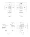
- FIG. 1 is a schematic drawing illustrating an apparatus for performing error concealment according to an embodiment.
- FIG. 2 is a schematic drawing illustrating an apparatus for performing error concealment according to a further embodiment
- FIG. 3 is a schematic drawing illustrating a decoding system including the apparatus for performing error concealment according to an embodiment
- FIG. 4 is a flow chart illustrating the steps of a method for performing concealment of a block in a video frame according to an embodiment
- FIG. 5 is a flow chart illustrating a method for performing error concealment of a block in a video frame according to a further embodiment
- FIG. 6 is a flow chart describing additional steps which may be used in a method for performing error concealment of a block in a video frame according to an embodiment
- FIG. 7 is a schematic drawing illustrating a selection scheme for predictor motion vectors in a frame including a corrupted block according to an embodiment
- FIG. 8 is a schematic drawing illustrating an example of search window according to an embodiment
- FIGS. 9 and 10 are schematic drawings illustrating possible recovery order schemes for sub-blocks of a corrupted frame according to an embodiment
- FIG. 11 is a schematic drawing illustrating the computation of a boundary matching metric according to an embodiment
- FIG. 12 is a schematic drawing illustrating the computation of a boundary matching metric according to another embodiment
- FIGS. 13-18 are plots comparing results obtained by a method and apparatus according to an embodiment with results obtained using standard techniques
- FIGS. 19-20 are schematic drawings illustrating the effect on the correction performed with a method and apparatus according to an embodiment
- FIG. 21 is a schematic drawing illustrating the computation of a boundary matching metric according to a conventional technique.
- macroblock and “block” are used with the same meaning and with the term “sub-block” is indicated the constituting parts of a macroblock.
- An embodiment is based on the observation that commonly used error concealment methods are based on schemes for selecting a correctly received block to be used for replacing a missing block, which are not capable of reliably reconstructing small details and fine movements. Moreover, although some known reconstruction schemes use a fine subdivision of the lost block, they do not consider motion characteristics of the area surrounding the lost block. Finally, even if some methods, such as interpolative techniques on 4 ⁇ 4 blocks, take into account the motion vectors for determining the best replacement for a lost block, they consider the motion characteristics in a static manner and thus do not allow using the motion vectors that better predict the motion of the sequence. The known methods may, therefore, produce reconstructed images, which appear as highly fragmented.
- an apparatus for performing error concealment is adapted to reconstruct a lost block by using sub-blocks of a reference frame, which minimize a cost function that takes into account a constraint term based on the distance of a candidate motion vector of a correctly received block adjacent the lost block from a reference motion vector, and a measure of the distortion between a candidate sub-block pointed at by the candidate motion vector and the block surrounding the lost block.
- the reference motion vector is defined by a combination of motion vectors corresponding to correctly received sub-blocks surrounding the lost block.
- An embodiment of the cost function defined above allows determining a replacement block which takes into account not only the smoothness of the recovered area across the borders between different blocks by minimizing the luminance distortion, but also allows choosing the block corresponding to a motion vector that more closely reflects the motion characteristics of the blocks surrounding the missing one.
- an embodiment defines a criterion that not only allows reducing the distortion between a candidate sub-block and correctly received sub-blocks surrounding the lost block, but also increases the coherency of the motion vectors belonging to said blocks.
- FIG. 1 illustrates an error concealment apparatus 100 according to an embodiment.
- the error concealment apparatus 100 may receive a corrupted frame including one or more lost blocks. If more than one macroblock is missing from the corrupted frame, the missing macroblock(s) may be recovered starting from the outer regions of the video frames and converging towards the center, according to what is done in the JVT scheme. As an example, the missing block may correspond to a macroblock of 16 pixels and may be divided into 16 4 ⁇ 4 sub-blocks. However, the present disclosure is not limited to such a solution and may as well work on macroblocks subdivided into four 8 ⁇ 8 blocks, or two 8 ⁇ 16 or 16 ⁇ 8 blocks, etc.
- a selection unit 120 is adapted to gather or select the motion vectors of correctly received or previously recovered blocks that surround the lost macroblock. Depending on the coding scheme used for the frame, the selection unit 120 may find one correctly received motion vector for each adjacent block or it may find a motion vector for each sub-block constituting the correctly received block. The motion vector may be included as information coded in each block/sub-block in the corrupted frame currently decoded. The motion vectors coded in correctly received blocks are indicated herein with the terms predictor motion vectors or predictors. An example of a selection scheme for predictor motion vectors will be described with more details with reference to FIG. 7 .
- the selection unit 120 further determines, based on the selected predictor motion vectors, a list of candidate motion vectors, which may be used for determining the best replacement motion vector.
- the determined list of candidate motion vectors is output into a fetching unit 130 adapted to access one or more correctly received frames.
- determining is meant, here and in the following, any operation aiming at obtaining a set of motion vectors which may be used for finding a replacement for a lost sub-blocks. Determining candidate vectors may, for instance, include selecting at least one vector among a set of available motion vectors or generating at least one vector based on available information.
- motion vectors may be included as motion information in each decoded sub-block and the list of candidate motion vectors may include all the motion vectors whose components lie within the maximum and minimum components among the predictor motion vectors.
- the candidate motion vectors may be generated based on the predictor motion vectors, i.e. by combining them, or may be generated using interpolative techniques.
- the aforementioned frames which will be referred to as “reference frames” throughout the application may include frames temporally preceding the corrupted frame or frames temporally following the corrupted frame.
- these frames are normally used for coding an actual frame as a difference with respect to the preceding/following one and therefore are also available to the error concealing apparatus.
- the fetching unit 130 can therefore fetch in a reference frame a plurality of correctly received sub-blocks pointed at by the generated candidate motion vectors.
- a matching unit 140 is adapted to receive as input the generated motion vectors and the sub-blocks in the reference frame pointed at by the generated motion vectors.
- Each pair of replacement candidate sub-block and motion vector is then inserted in a suitable cost function, which will be evaluated for each pair of candidate motion vector and candidate sub-block in order to determine the candidate pair that is more suitable for replacing the missing sub-block.
- an important task of an embodiment of the selection unit 120 is determining the candidate motion vectors. Once the candidate motion vectors are known, the choice of a candidate sub-block in the reference frame is univocal.
- the error concealment apparatus 100 includes a fetching unit 130 , the task performed by this unit may be as well performed by the selection unit 120 .
- the constraint term in the cost function may be defined as a norm of the difference between the candidate motion vector and the reference motion vector.
- the reference motion vector may be defined as the average of the selected predictor motion vectors.
- average of the predictor motion vectors here and throughout the application is meant any one of an arithmetic mean of the components of the vectors, a geometric or quadratic mean of the components of the selected predictor motion vectors or a median or geometric median, etc.
- the constraint term appearing in the cost function may also be multiplied by a weighting factor.
- the matching unit 140 may be further adapted to determine the weighting factor in an optimal manner.
- the value of the weighting factor, which minimizes the distortion may fall in the range of 0.02 to 0.3. This value may be, however, derived experimentally, and may depend on the decoded frame and the testing conditions, such as resolution and the like. More precisely, the optimal weighting factor may be estimated by pretending that a few correctly received blocks are instead lost. At this point, one may perform the recovery procedure for different values of the weighting factor and determine the value that minimizes the reconstruction distortion between two correctly received sub-blocks.
- the measure of the distortion between the replacement sub-block and a correctly received sub-block adjacent to the current block is an outer boundary matching algorithm metric (OBMA).
- OBMA outer boundary matching algorithm metric
- the outer boundary matching algorithm may be defined as the sum of absolute differences between the outer boundary pixels of the candidate sub-block and the boundary pixels of the sub-block adjacent to the lost one.
- the outer boundary matching algorithm may alternatively be evaluated on a two pixel thick boundary.
- the selection unit 120 may be further adapted to generate in the reference frame a search window, which is defined so as to include the prediction motion vectors.
- the selection unit 120 will subsequently generate as candidate motion vectors all the motion vectors pointing within the defined search window. In the application, this concept is expressed by saying that the candidate motion vectors are generated in the search window.
- the dimensions of the search window may be reduced to predefined dimensions.
- the selection unit 120 may center the reduced search window on the average predictor motion vector. Accordingly, the apparatus may still be capable of performing error concealment in real time without deteriorating the performance of the apparatus.
- the selection unit 120 may be adapted to define in the reference frame a search window centered on the average motion vector.
- the selection unit 120 may alternatively generate candidate motion vectors pointing within a plurality of search windows, each search window being centered on a predictor motion vector.
- the selection unit 120 may be set so that if the components of two or more predictor motion vectors differ less than a predefined threshold, only one search window for all said predictor motion vectors will be defined. This allows reducing the computational load required for determining the candidate motion vectors without deteriorating the quality of the replacement procedure.
- the matching unit 140 may determine a replacement motion vector.
- said replacement motion vector may be fed back into the selection unit 120 .
- the selection unit 120 may define in the reference frame a refinement search window of a predefined size and centered on the replacement motion vector and generate refined candidate motion vectors within the refinement search window.
- the matching unit 140 may at this point select, among the refined candidate motion vectors, a refined replacement motion vector that minimizes the cost function computed at a higher pixel resolution. This procedure, may be repeated for instance at 1 ⁇ 2 pixel precision and at 1 ⁇ 4 pixel precision.
- the predefined size may be chosen so as to define a refinement search window smaller than the starting reference window. An example of the refinement procedure is discussed with further details with reference to FIG. 8 .
- An advantage of an embodiment is that the search procedures at higher pixel resolution may be performed on windows of a predefined size which is smaller than the size of the starting window.
- the refinement window may be, for instance, a 2 ⁇ 2 pixel window. Obtaining reliable results performing a refined search in a small refinement window may be possible because the refinement search window is centered on the replacement vector. Indeed, once a candidate for a replacement motion vector has been selected, it is expected that the motion vector that produces the best results lies in a relatively small area around the selected replacement vector. Since the area to be searched is now reduced, it may be possible to perform a higher pixel search without requiring high computational power.
- FIG. 2 shows an alternative embodiment of an error concealment apparatus 101 .
- the error concealment apparatus 101 includes further to all the elements described with reference to FIG. 1 also a scan order decision unit 110 capable of determining the recovery order of the sub-blocks of the lost block.
- the list of corrupted blocks is input into the scan order decision section 110 which selects the recovery order using an adaptive procedure. More precisely, the sub-blocks surrounded by the highest number of correctly received sub-blocks will be recovered first. Once one sub-block is recovered, it is included in the list of correctly received sub-blocks.
- An embodiment of the adaptive recovery procedure will be more clearly explained with reference to FIGS. 9 and 10 .
- FIG. 3 shows an embodiment of a decoding apparatus for decoding video frames including the error concealment apparatus 100 or 101 according to an embodiment.
- the decoding system 200 further includes a first memory 210 adapted to store at least one reference frame and a second memory 220 to store the current frame (eventually corrupted).
- the decoding system 200 may further include a decoding unit 230 configured to decode received frames and to feed correctly decoded reference frames into the memory 210 . Further, the decoding unit 230 may also be configured to extract from the correctly received reference frames, a reference motion vector's field.
- the reference motion vector field includes the predictor motion vectors, which may be fed from the memory 210 to the selection unit 120 .
- the extraction of the predictor motion vectors is carried out in the decoding unit 230 and the selection unit 120 only needs to select the predictor motion vectors associated with the block currently concealed.
- the selection unit 120 may also be configured to perform the extraction of the predictor motion vectors for a current block to be concealed.
- the decoding system 200 includes a first and a second memory 210 , 220 , it may be possible to configure the decoding system 200 so as to have only a memory adapted to store both the reference frames and the current frame, wherein for current frame is intended the frame on which error concealment is performed.
- FIG. 4 is a flow chart describing an embodiment of a method for performing error concealment of a block in a video frame.
- the block is subdivided into a plurality of sub-blocks.
- predictor motion vectors of available sub-blocks, i.e. correctly received or successfully recovered sub-blocks, surrounding a current block are selected.
- FIG. 7 An embodiment of a scheme describing how the predictor motion vectors or simply predictors may be selected is shown in FIG. 7 . Although described in relation to FIG. 4 , this scheme is general and may as well be used in other embodiments.
- the predictor motion vectors are all the available motion vectors of the sub-blocks surrounding the corrupted block in the current frame (the central block in the figure).
- the example in FIG. 7 illustrates a block composed of 16 4 ⁇ 4 sub-blocks and, in this case, the predictor motion vectors will be the available motion vectors of the 20 sub-blocks adjacent to the borders of the corrupted block including the sub-blocks at the edges.
- the blocks on the top, bottom and left of the lost block are correctly received, while the block at its right is corrupted.
- the correctly received sub-blocks are 16 and therefore the number of predictors will be at most 16. This number may be reduced if two or more sub-blocks have the same motion vector.
- the set of predictor motion vectors may include all the motion vectors of these sub-blocks.
- the motion vectors of the 20 sub-blocks it may also be possible to consider the zero motion vector and the average of the available motion vectors in the sub-blocks surrounding the lost block, i.e. the average predictor motion vector.
- a 4 ⁇ 4 sub-block adjacent to the lost block may inherit the motion vector of a larger block that contains it. In this case sub-blocks belonging to the same block will have the same motion vector.
- step 320 candidate motion vectors are determined based on the selected predictor motion vectors.
- the candidate motion vectors may be determined once for the current block or, alternatively may be generated for each sub-block of the current block.
- the selection of predictors and the generation of the candidate motion vectors may be performed by a selecting unit as the one described with reference to FIGS. 1 to 3 .
- step S 330 for each sub-block of the current block, a replacement motion vector among the candidate motion vectors is selected so as to minimize a cost function. Step 330 may be performed by a matching unit as described with reference to FIGS. 1 to 3 .
- An embodiment of the cost function is a sum of two terms and is evaluated for each candidate motion vector.
- the cost function is a sum of a constraint term based on the distance of a candidate motion vector from a reference motion vector.
- the second term of the cost function is a measure of the distortion between a candidate sub-block in the reference frame pointed to by the candidate motion vector for which the cost function is evaluated and a correctly received or previously concealed sub-block adjacent to said sub-block in the current block.
- the reference motion vector is obtained by a combination of the selected predictor motion vectors.
- FIG. 5 is a flow chart describing a method according to a further embodiment. Steps S 410 to S 430 correspond to steps S 310 to S 330 described with reference to FIG. 4 . In addition, in step S 401 it is determined the recovery order of the sub-blocks of the missing block. This step will be described with more details with reference to FIGS. 9 and 10 . Although the flow chart of FIG. 4 includes step 401 , and a suitable choice of the recovery order may improve the performance of the method and the quality of the reconstruction, an embodiment of the error concealment method may omit this step, which is optional.
- step S 440 it is determined whether the replacement motion vector was determined by evaluating the cost function at a maximum predefined pixel precision.
- the maximum pixel precision may be defined depending on the coding scheme and on the motion characteristics of the area surrounding the missing block. In an embodiment, for maximum precision, it is intended that the search of the replacement motion vector is performed with a resolution of 1 ⁇ 4 pixel precision or more. More precisely, an embodiment determines at a first step a replacement motion vector by evaluating the cost function at a predetermined pixel precision. If said pixel precision does not coincide with the maximum pixel precision, the search is refined by increasing the pixel precision and performing step S 420 and S 430 again. In conclusion, steps S 420 to S 450 are repeated until the desired precision is reached. The precision may be incremented by a factor of, for example, 1 ⁇ 2 at each repetition. However, the incrementing step may be different depending on the application.
- FIG. 6 depicts a flow chart describing in further detail an embodiment of how the candidate motion vectors are generated in step S 420 .
- Step S 510 in FIG. 5 decides whether a replacement motion vector has already been selected. If the answer is NO, the control passes to step S 530 .
- step S 530 it is decided whether the method is a fast search method and in the affirmative case steps S 531 and S 532 are performed.
- the steps S 530 to S 532 summarize an embodiment of the fast search method. This embodiment is based on the idea of starting from a motion vector and performing the search of the replacement motion vector by determining candidate motion vectors around the selected starting vector. Once a local minimum for a particular cost function is found, then the same analysis is performed around said local minimum. The process goes on until convergence, i.e. until no better solutions can be found.
- step S 531 the set of prediction motion vectors selected in step S 410 is considered.
- the number of predictor motion vectors is eventually reduced. More precisely, it may occur that starting from two predictor motion vectors whose components differs less than a predetermined threshold value, the search of the best replacement motion vector converges to the same vector.
- the predictor motion vectors selected in step S 410 are redundant and, for efficiency purposes, may be eliminated from the list. Consequently, the list of predictor motion vectors is chosen so as to include only vectors whose distance from the other motion vectors in the list is larger than a certain threshold.
- a threshold value d min may be fixed so that when the difference of both components of two predictor motion vectors is larger than said threshold value d min , the two vectors are included in the list. Otherwise, one of the two vectors is excluded.
- the threshold value may be optimally determined based on the requested precision.
- a search window of a predefined size is defined in the reference frame.
- a set of candidate motion vectors pointing within the defined search windows is created at step S 570 and subsequently the replacement motion vector is selected as described already with reference to steps S 420 to S 415 .
- FIG. 8 schematically illustrates a search window which may be defined in step S 532 .
- a search window of 2 ⁇ 2 pixels centered on the predictor motion vector may be defined.
- a local minimum of the cost function is determined and a new window of 2 ⁇ 2 pixels centered on the determined local minimum is defined.
- the process is iterated until the value of the cost function evaluated on the vectors belonging to the new window decreases. Otherwise, if the predictor motion vectors in the new window cause the cost function to increase, the process is stopped and the replacement motion vector among the ones previously tried, which produces the smallest value of the cost function, is chosen as the best motion vector for the window.
- the process may also be stopped if the distance between the selected replacement motion vector and the starting prediction motion vector exceed a certain threshold value.
- each sub-block may include a list of all the vectors already tested. In this manner, if two subsequently defined windows include the same vector, one of these may be skipped, thereby increasing the performance of the method.
- the search window is a 2 ⁇ 2 pixel window, it is understood that one may also choose a smaller or bigger window according to the coding scheme and the precision required.
- An advantage of the embodiment described in steps S 530 to S 532 and S 570 ( FIG. 6 ) with respect to other methods is that for a search window of predefined dimensions, the maximum number of analyses to be performed increases in a linear manner with the maximum set distance between the predictor and the search window, while other methods tends to perform a number of analyses that grows quadratically with the size of the search window.
- Step S 540 summarizes the idea of a full search scheme.
- the full search scheme is based on the idea that if correctly received blocks surrounding the lost block have different motion vectors, a search method based on the choice of one among these motion vector will privilege only one among the described movement. In particular, the metric will choose the motion vector describing the movement that minimizes the distortion in the luminance.
- discarding already received motion vectors for performing the search may lead to finding a non-optimal replacement sub-block. In order to obviate this drawback, an embodiment described in FIG.
- the search window may either be defined through the coordinates of its edges (the top left corner and bottom right corner), or through the range within which the motion vector is varied in order to find the luminance sub-blocks to be tested.
- the window may include areas of the reference frame that do not correlate with the lost block in the current frame. This effect is increased if the error concealment is performed on a block subdivided in sub-blocks including few pixels. As an example, if the missing block is sub-divided into 16 sub-blocks of 4 ⁇ 4 pixels, it may occur that the method chooses a replacement sub-block, which is not correlated with the lost sub-block, but has a similar border.
- window dimensions may be chosen according to the format of the video frames. More precisely, a search window suitable for a QCIF format (176 ⁇ 144) may not be suitable for a CIF format (352 ⁇ 288).
- an embodiment adaptively defines the search window based on the motion characteristics within the correctly received blocks adjacent to the lost block. Accordingly, if the motion is uniform and homogeneous, the search windows may be rather small, whereas if the motion is irregular, the search window may be larger.
- the search window is determined based on the motion vectors of correctly received sub-blocks surrounding the lost block.
- step S 540 it is determined whether the number of available motion vectors surrounding the lost block is larger than a certain threshold number. In case the number of predictor motion vectors is smaller than a predefined threshold number, a search window defined based on the predictor motion vectors is not considered reliable and the control passes to step S 541 .
- the threshold number may be 4. However, this threshold may vary from case to case.
- step S 541 is executed. Accordingly, the available predictors are averaged so as to obtain an average predictor motion vector and a search window of a predefined dimension centered on the average motion vector is defined in the reference frame.
- the search window may be a 4 ⁇ 4 pixels window. However, depending on the format of the video frames, the dimensions of the search window may be extended or reduced.
- a set of candidate motion vectors pointing within the defined search windows is created at step S 570 and subsequently the steps S 430 to S 450 described with reference to FIG. 5 are executed in order to select the best candidate for a replacement motion vector.
- the search window of predefined dimensions may be centered on the null vector.
- step S 550 is executed.
- a search window is defined, which will then be used for determining the replacement motion vector of each sub-block in the current lost block.
- the search window may be centered on the zero motion vector or on the average predictor motion vector and subsequently the motion vectors of the correctly received sub-blocks surrounding the lost macroblock are chosen. As already described with reference to FIG. 7 , the selected predictor motion vectors may be at most 20.
- the search window in the reference frame will be defined by the set ⁇ min v x i , . . . , max v x i ⁇ min v y i , .
- step S 560 the window dimensions are analyzed and, if said dimensions exceed a predefined window threshold value, the dimensions of the search window are reduced.
- the threshold number for the predictors may be set to 4. However, this number may be adapted to the particular coding scheme and to the precision required.
- This step may be useful if a lost block belongs to a frame whose motion characteristics are irregular.
- the search window defined in the reference frame in step S 550 may be rather large.
- the window threshold is set as the maximum window size, which may be used in real time applications, the method may still be used in real time.
- the search window may be, for instance, reduced to the maximum allowed dimensions for performing real time decoding or may be reduced to a predefined search window according to the used coding scheme.
- the search window in the reference frame may be centered on the average predictor motion vector. In this manner, the search window will define the area in the reference frame, which will most likely include the best replacement motion vector.
- step S 561 The reduction of the window dimensions is performed in step S 561 .
- step S 570 a set of candidate motion vectors is generated in the previously defined search window in the reference frame.
- step S 560 it is determined that the dimensions of the window defined in step S 550 do not exceed the window threshold, step S 570 is performed in order to generate candidate motion vectors in the search window defined in step S 550 .
- the method proceeds then with steps S 430 to S 450 in FIG. 5 .
- steps S 560 and S 561 when the search window is made smaller, it may happen that the new motion vector is excluded from the search window. This may happen especially during recovering of sub-blocks close to the border of the frame.
- a search window centered on the zero motion vector is opened and the cost function is evaluated on motion vectors generated to said search window.
- the cost function may be evaluated only taking into account the luminance distortion between a candidate sub-block in the reference frame and a correctly received sub-block adjacent to the sub-block to be replaced.
- steps S 510 to S 570 where all included in a single flow chart, it is clear that an embodiment does not necessarily require all the steps, and a error concealment apparatus may also be configured to perform only a subset of the steps described in FIG. 6 .
- FIGS. 9 and 10 schematically describe the order in which the sub-blocks are recovered within the missing block. This task may be performed by the scan order decision section 110 . Alternatively, it may be performed directly in the selection unit 120 .
- the lost block has been sub-divided in 16 sub-blocks of 4 ⁇ 4 pixels.
- another choice for the subdivision may be chosen based on the nature of the video sequence and on the used coding scheme.
- the choice of subdividing the missing block in 4 ⁇ 4 sub-blocks may allow following in a reliable manner complex movements.
- Subdividing the block into 16 sub-blocks may require defining an efficient recovery order for the sub-blocks. It may be important to maximize the number of correctly received or already recovered pixels adjacent to the sub-block being actually recovered.
- the recovery order of the sub-blocks may vary depending on the location of the correctly received blocks surrounding the missing one, and, therefore, it is possible to adapt it based on the context of the area surrounding the missing block.
- the recovery order may be decided based on the 16 sub-blocks adjacent to the sub-blocks defining the borders of the missing block or edge sub-blocks. Accordingly, the edge sub-blocks in the missing block are recovered starting from the sub-blocks that have a higher number of adjacent correctly received pixels. The recovery then proceeds from the edges of the missing macroblock to the internal sub-blocks of the missing macroblock.
- FIG. 9 illustrates a situation, wherein the top and bottom blocks are correctly received while the right block is corrupted.
- the left block was previously recovered in this procedure.
- the previously recovered macroblocks are considered to have the same importance as correctly received macroblocks.
- the top left and bottom left sub-blocks of the block to be recovered both have two recovered/correctly received adjacent sub-blocks.
- the top left sub-block may be recovered first followed by the bottom left sub-block.
- the bottom left sub-block may be recovered first followed by the top left sub-block. Once the first two blocks are recovered, they may be considered as correctly received in the recovery procedure.
- the sub-block below the top left block will now have two adjacent recovered sub-blocks as well as the sub-block immediately above the bottom left sub-block. Therefore, these two blocks will be recovered as next starting from top and going towards the bottom.
- the newly recovered sub-block within the missing macroblock will be subsequently used in order to determine which sub-block has to be recovered next.
- the sub-blocks of the missing macroblock will be recovered from left to right within the block and from the borders to the center within the columns in an alternate manner.
- another scheme may also be applied for deciding the recovery order sub-blocks surrounded by the same number of correctly received pixels.
- FIG. 10 illustrates a different situation in which only the blocks at the bottom and on the left of a missing macroblock are correctly received/recovered, while the blocks at the top and on the right are not yet received.
- the sub-block at the bottom left edge may be recovered first followed by the sub-block above the bottom left block.
- the distortion caused by the replacement may be calculated according to several designs and algorithms. Moreover, each of the algorithms calculating the distortion may be evaluated on a border of one or more pixels.
- a first choice for the metric in the cost function may be the boundary-matching algorithm (BMA).
- BMA boundary-matching algorithm
- ⁇ tilde over (Y) ⁇ p′ i is the luminance value of the candidate replacement sub-block in the reference frame
- Y q i is the luminance value of the correctly received sub-block adjacent the sub-block to be recovered in the lost block.
- This metric may allow choosing the sub-block that maximizes the smoothness of the border between two blocks, thereby avoiding big luminance discontinuities across the borders.
- a problem that may occur using this metric is that if the metric is calculated on 4 ⁇ 4 sub-blocks, the distortion may be evaluated only on 8 pixels. Consequently, the metric may select as a best replacement sub-block, the sub-block having a border similar to the border of the correctly received sub-block adjacent to the missing one. In this manner, the replacement block is chosen according to the border characteristics. This behavior however, may lead to bad results if applied to an area crossed by oblique edges.
- an overlapping BMA (OBMA) metric may be used.
- the distortion is evaluated taking into account only one side of the border between the lost block and the correctly received block in the reference frame.
- OBMA overlapping BMA
- a sum of the absolute differences is evaluated between the luminance values of the boundary pixels outside the candidate replacement sub-block and the boundary pixels outside the sub-block to be recovered. Accordingly, the metric is given by:
- ⁇ tilde over (Y) ⁇ p′′ i is the luminance value of the pixels outside the boundary of the candidate replacement sub-block in the reference frame
- Y q i is the luminance value of the correctly received sub-block adjacent the sub-block to be recovered in the lost block.
- this technique may favor replacement sub-blocks that assure a better continuity among correctly received sub-blocks. In other words, this embodiment chooses as a replacement the sub-block in the reference frame, which has the same contour of pixel of the missing sub-block.
- this metric further allow deciding the number of border pixels on which the distortion is evaluated. This may allow increasing the pixels used for determining the replacement sub-block. On the other hand, using a large number of border pixels may increase the possibility of including pixels in the evaluation that do not correlate with the sub-block to be recovered. Experimental comparison between sub-blocks recovered using a one-pixel border and a two-pixel border showed that the selection carried out by evaluating the metric on a two-pixel border gave better results.
- the IN-IN metric with extrapolation Another example of a metric that may be used in the algorithm is the IN-IN metric with extrapolation.
- the aim of this metric is to avoid the polarization phenomenon that leads to a deterioration of the border which may occur if the BMA metrics is used.
- the external and internal areas of a sub-block to be replaced are compared, giving more importance to the comparisons between overlapping areas.
- the IN-IN metric compares internal areas. In other words, a sum of the absolute difference between the pixels on the internal border of the candidate sub-block and the pixels on the internal border of the lost sub-block is evaluated.
- the internal borders of the lost sub-block do not include any luminance values, these values will be extrapolated.
- Y T ( x,y ) Y ( x,y ⁇ 1)+[ Y ( x,y ⁇ 1) ⁇ Y ( x,y ⁇ 2)] (3.1)
- Y B ( x,y ) Y ( x,y+ 1)+[ Y ( x,y+ 1) ⁇ Y ( x,y+ 2)] (3.2)
- Y L ( x,y ) Y ( x ⁇ 1 ,y )+[ Y ( x ⁇ 1 ,y ) ⁇ Y ( x ⁇ 2 ,y )] (3.3)′
- Y R ( x,y ) Y ( x+ 1 ,y )+[ Y ( x+ 1 ,y ) ⁇ Y ( x+ 2 ,y )] (3.4)
- FIG. 12 illustrates an example of the IN-IN metric, wherein the values in the lost block were recovered based on the luminance values of a 2-pixels border of correctly received sub-blocks surrounding the lost block.
- the cost function is given by a sum of a metric for calculating the luminance distortion and a constraint term taking into account the distance between the candidate motion vector currently analyzed and a reference vector obtained by calculating the average of the available predictor motion vectors of correctly received sub-blocks surrounding the lost macroblock.
- the second term forces a choice of the sub-blocks pointed to by the motion vector which is closer to the average predictor. In this manner, it may be possible also use in the selection process of the best replacement candidate information relating to motion characteristics of the blocks.
- the first term on the right hand side of equation (4) is the metrics, which gives a measure of the distortion between a candidate sub-block in the reference frame and a correctly received sub-block adjacent the sub-block in the currently decoded block.
- the second term on the right hand side of equation (4) is the constraint term representing the distance of a candidate motion vector from a reference motion vector.
- the distance of the candidate motion vector from the average predictor is calculated as a quadratic norm, any other expression indicating a relative position between the candidate vectors and the average predictor may be used.
- the term ⁇ is a weighting factor, whose optimal value may be determined experimentally based on the video sequence currently decoded.
- the OBMA metric may be calculated on a two pixels border.
- FIGS. 13 and 14 show an example of the gain that may be achieved by adding the constraint term as a function of lambda as described in equation (4).
- PSDa peak signal-to-noise ratio
- the weighted constraint term may allow improving the quality of reconstructed video frames
- an embodiment of the algorithm has been proven to be robust with respect to variations of ⁇ within a certain predefined range.
- the value of ⁇ is not critical for the performance of the algorithm if said value is chosen within a predefined range, which may be determined experimentally.
- the best result is obtained for a value of ⁇ of approximately 0.02, any value in the interval between 0.02-0.3 may be used without substantially affecting the reconstruction quality of the video frame.
- FIG. 14 shows a plot of the same quantities as plotted in FIG. 13 for a different video sequence (“mobile” sequence).
- the value of ⁇ for which the best results are obtained is higher and is around 0.2.
- deviations from the best possible result are within a range of 0.4 dB for values of ⁇ comprised between 0.02 and 0.3.
- any value in the interval between 0.02-0.3 may be used without substantially affecting the reconstruction quality of the video frame.
- each sub-block adjacent to the lost block may include a vector referring to a previous frame and a vector referring to a following frame.
- an embodiment of the method defines for each sub-block a backward window and a forward window. All the steps described with reference to FIGS. 4 to 6 may be performed in both reference frames. Accordingly, an embodiment of the method minimizes a cost function defined in the backward window and a cost function defined in the forward window.
- the matching section will decide whether to select the motion vector in the backward window or the motion vector in the forward window. This choice may, for instance, be done by choosing the best predictor that gives the smallest value among the cost functions calculated in the backward and forward frame.
- FIGS. 19 and 20 are schematic drawings showing the reconstruction of a corrupted block using a standard method and a method according to an embodiment.
- IDR frame reference frame
- P-frame predictive coded frame
- FIG. 19 shows a simple example, wherein a block is missing in the center of the frame.
- the IDR frame is the correctly received frame, while the P-frame is to be corrected.
- a standard method that subdivides the missing block into sub-blocks including more than four pixels per side may not be able to correctly recover the image, which may then appear fragmented as is evident from the bottom left and right picture of FIG. 19 .
- the P-frame is obtained by translating the previous frame (reference frame) to the right by d. Also in this case, we consider a missing block in the P frame and all the blocks surrounding the missing blocks are included with a given motion vector pointing to an area in the reference frame to the left of the missing block.
- the reconstructed frame below the reference frame was obtained by performing a standard full search algorithm on a search window of a predefined size centered on the zero vector. In this case, the search window covers the area in a range [ ⁇ d/2, d/2] and will therefore not include the vector d, thereby producing a fragmented, reconstructed image.
- the search window includes the vector d, and therefore, leads to the result depicted in the bottom left frame.
- a further embodiment relates to the implementation of the above-described various embodiments using hardware and software. It is recognized that various embodiments may be implemented or performed using computing devices (processors).
- a computing device or processor may, for example, be a general-purpose processor, digital-signal processor, etc. Various embodiments may also be performed or embodied by a combination of these devices. Further, various embodiments may also be implemented by software modules, which are executed by a processor or directly in hardware. Also a combination of software modules and hardware implementation may be possible.
- the software modules may be stored on any kind of computer-readable storage media, for example, RAM, IPROM, EPROM, flash memory registers, hard disk, etc.
- an embodiment relates to performing error concealment of a corrupted block in a video frame, which is capable of performing a real time reconstruction of corrupted blocks which allows to precisely recover small details and fine movements
- an embodiment of an error concealment apparatus and method selects a replacement block by taking into account the luminance distortion and the motion characteristics of the video sequence. The latter is represented by the distance of the motion vectors chosen as candidate replacements and the average value of the motion vectors of the blocks surrounding the missing block in the current frame.
- a system such as a computer or video system may include a video decoder incorporating an embodiment of a lost-block recapture technique as described above. Components of the system may be disposed on a same or respective integrated-circuit dies.
Abstract
Description
where {tilde over (Y)}p′
where {tilde over (Y)}p″
Y T(x,y)=Y(x,y−1)+[Y(x,y−1)−Y(x,y−2)] (3.1)
Y B(x,y)=Y(x,y+1)+[Y(x,y+1)−Y(x,y+2)] (3.2)
Y L(x,y)=Y(x−1,y)+[Y(x−1,y)−Y(x−2,y)] (3.3)′
Y R(x,y)=Y(x+1,y)+[Y(x+1,y)−Y(x+2,y)] (3.4)
where YT, YB, YL and YR are the extrapolated luminance values on each side of a sub-block in the lost block. Since following this embodiment, pixels at the edges of sub-blocks are extrapolated twice, the two values will be combined so as to obtain a mean value.
cos t MV =D OBMA +λ∥{right arrow over (v)} i−
wherein {tilde over ({right arrow over (v)})} is an average predictor obtained by averaging the components of all the available predictors for the lost block and {right arrow over (v)}i is the i-th candidate motion vector. The first term on the right hand side of equation (4) is the metrics, which gives a measure of the distortion between a candidate sub-block in the reference frame and a correctly received sub-block adjacent the sub-block in the currently decoded block. The second term on the right hand side of equation (4) is the constraint term representing the distance of a candidate motion vector from a reference motion vector. Although in equation (4) the distance of the candidate motion vector from the average predictor is calculated as a quadratic norm, any other expression indicating a relative position between the candidate vectors and the average predictor may be used. The term λ is a weighting factor, whose optimal value may be determined experimentally based on the video sequence currently decoded. Moreover, the OBMA metric may be calculated on a two pixels border.
Claims (38)
Priority Applications (1)
| Application Number | Priority Date | Filing Date | Title |
|---|---|---|---|
| US12/954,341 US8976873B2 (en) | 2010-11-24 | 2010-11-24 | Apparatus and method for performing error concealment of inter-coded video frames |
Applications Claiming Priority (1)
| Application Number | Priority Date | Filing Date | Title |
|---|---|---|---|
| US12/954,341 US8976873B2 (en) | 2010-11-24 | 2010-11-24 | Apparatus and method for performing error concealment of inter-coded video frames |
Publications (2)
| Publication Number | Publication Date |
|---|---|
| US20120128071A1 US20120128071A1 (en) | 2012-05-24 |
| US8976873B2 true US8976873B2 (en) | 2015-03-10 |
Family
ID=46064360
Family Applications (1)
| Application Number | Title | Priority Date | Filing Date |
|---|---|---|---|
| US12/954,341 Expired - Fee Related US8976873B2 (en) | 2010-11-24 | 2010-11-24 | Apparatus and method for performing error concealment of inter-coded video frames |
Country Status (1)
| Country | Link |
|---|---|
| US (1) | US8976873B2 (en) |
Cited By (2)
| Publication number | Priority date | Publication date | Assignee | Title |
|---|---|---|---|---|
| CN110291790A (en) * | 2017-04-07 | 2019-09-27 | 华为技术有限公司 | Motion vector (MV) constraint and transformation constraint in Video coding |
| US10536723B2 (en) * | 2016-09-08 | 2020-01-14 | Applied Research, LLC | Method and system for high performance video signal enhancement |
Families Citing this family (29)
| Publication number | Priority date | Publication date | Assignee | Title |
|---|---|---|---|---|
| JP5091994B2 (en) * | 2010-09-02 | 2012-12-05 | 株式会社東芝 | Motion vector detection device |
| GB2487200A (en) | 2011-01-12 | 2012-07-18 | Canon Kk | Video encoding and decoding with improved error resilience |
| ES2621231T3 (en) | 2011-04-12 | 2017-07-03 | Sun Patent Trust | Motion video coding method, motion video coding apparatus, motion video decoding method, motion video decoding apparatus and motion video coding / decoding apparatus |
| PL2717575T3 (en) | 2011-05-27 | 2019-03-29 | Sun Patent Trust | Image decoding method and image decoding device |
| US9485518B2 (en) | 2011-05-27 | 2016-11-01 | Sun Patent Trust | Decoding method and apparatus with candidate motion vectors |
| JP5937589B2 (en) | 2011-05-31 | 2016-06-22 | パナソニック インテレクチュアル プロパティ コーポレーション オブ アメリカPanasonic Intellectual Property Corporation of America | Moving picture decoding method and moving picture decoding apparatus |
| GB2491589B (en) * | 2011-06-06 | 2015-12-16 | Canon Kk | Method and device for encoding a sequence of images and method and device for decoding a sequence of image |
| EP2728878B1 (en) | 2011-06-30 | 2020-02-19 | Sun Patent Trust | Image decoding method, image encoding method, image decoding device, image encoding device, and image encoding/decoding device |
| CN106131572B (en) * | 2011-07-06 | 2019-04-16 | Sk 普兰尼特有限公司 | The picture coding device, motion estimation device and method of movement are estimated at high speed |
| GB2493210B (en) * | 2011-07-29 | 2014-04-23 | Canon Kk | Method and device for error concealment in motion estimation of video data |
| GB2493212B (en) * | 2011-07-29 | 2015-03-11 | Canon Kk | Method and device for error concealment in motion estimation of video data |
| MX341415B (en) | 2011-08-03 | 2016-08-19 | Panasonic Ip Corp America | Video encoding method, video encoding apparatus, video decoding method, video decoding apparatus, and video encoding/decoding apparatus. |
| CA2850595C (en) | 2011-10-19 | 2020-09-08 | Panasonic Corporation | Picture coding method, picture coding apparatus, picture decoding method, and picture decoding apparatus |
| GB2497915B (en) | 2011-10-25 | 2015-09-09 | Skype | Estimating quality of a video signal |
| GB2513090B (en) | 2013-01-28 | 2019-12-11 | Microsoft Technology Licensing Llc | Conditional concealment of lost video data |
| US10158889B2 (en) * | 2015-01-31 | 2018-12-18 | Intel Corporation | Replaying old packets for concealing video decoding errors and video decoding latency adjustment based on wireless link conditions |
| CN105791879B (en) * | 2016-03-04 | 2019-04-05 | 广东顺德中山大学卡内基梅隆大学国际联合研究院 | The compensation motion vector method and system of lost blocks in video code flow error concealing |
| KR20180021998A (en) * | 2016-08-23 | 2018-03-06 | 삼성전자주식회사 | Apparatus, data propcessing module and method for receiving video image |
| JP7260562B2 (en) * | 2018-01-29 | 2023-04-18 | ヴィド スケール インコーポレイテッド | Low complexity frame rate up conversion |
| CN111788829B (en) * | 2018-02-28 | 2022-02-08 | 三星电子株式会社 | Encoding method and device, and decoding method and device |
| WO2019191890A1 (en) * | 2018-04-02 | 2019-10-10 | 深圳市大疆创新科技有限公司 | Image processing method and image processing device |
| WO2019192301A1 (en) * | 2018-04-02 | 2019-10-10 | 深圳市大疆创新科技有限公司 | Method and apparatus for processing video image |
| KR102605638B1 (en) * | 2018-06-07 | 2023-11-22 | 베이징 바이트댄스 네트워크 테크놀로지 컴퍼니, 리미티드 | Partial Cost Calculation |
| TWI719519B (en) | 2018-07-02 | 2021-02-21 | 大陸商北京字節跳動網絡技術有限公司 | Block size restrictions for dmvr |
| WO2020098647A1 (en) * | 2018-11-12 | 2020-05-22 | Beijing Bytedance Network Technology Co., Ltd. | Bandwidth control methods for affine prediction |
| EP3915259A4 (en) | 2019-03-06 | 2022-03-30 | Beijing Bytedance Network Technology Co., Ltd. | Usage of converted uni-prediction candidate |
| WO2020247761A1 (en) * | 2019-06-07 | 2020-12-10 | Beijing Dajia Internet Information Technology Co., Ltd. | Sub-block temporal motion vector prediction for video coding |
| CN110856048B (en) * | 2019-11-21 | 2021-10-08 | 北京达佳互联信息技术有限公司 | Video repair method, device, equipment and storage medium |
| US11140416B1 (en) * | 2020-03-26 | 2021-10-05 | Tencent America LLC | Method and apparatus for temporal smoothing for video |
Citations (10)
| Publication number | Priority date | Publication date | Assignee | Title |
|---|---|---|---|---|
| US5737022A (en) * | 1993-02-26 | 1998-04-07 | Kabushiki Kaisha Toshiba | Motion picture error concealment using simplified motion compensation |
| US6512795B1 (en) * | 1997-09-12 | 2003-01-28 | Unisearch Limited | Error concealment for video services |
| US6590934B1 (en) * | 1998-08-20 | 2003-07-08 | Lg Electronics Inc. | Error concealment method |
| US20050141622A1 (en) * | 2003-12-24 | 2005-06-30 | Lg Electronics Inc. | Apparatus and method for recovering lost block of image processing system |
| US20060013320A1 (en) * | 2004-07-15 | 2006-01-19 | Oguz Seyfullah H | Methods and apparatus for spatial error concealment |
| US20070147506A1 (en) * | 2005-12-28 | 2007-06-28 | Samsung Electronics Co., Ltd. | Motion estimator and motion estimating method |
| US7324698B2 (en) * | 2003-11-20 | 2008-01-29 | Mitsubishi Electric Research Laboratories, Inc. | Error resilient encoding method for inter-frames of compressed videos |
| US20100118970A1 (en) * | 2004-12-22 | 2010-05-13 | Qualcomm Incorporated | Temporal error concealment for video communications |
| US20100290530A1 (en) * | 2009-05-14 | 2010-11-18 | Qualcomm Incorporated | Motion vector processing |
| US8165210B2 (en) * | 2007-12-17 | 2012-04-24 | Vixs Systems, Inc. | Video codec with shared interpolation filter and method for use therewith |
-
2010
- 2010-11-24 US US12/954,341 patent/US8976873B2/en not_active Expired - Fee Related
Patent Citations (10)
| Publication number | Priority date | Publication date | Assignee | Title |
|---|---|---|---|---|
| US5737022A (en) * | 1993-02-26 | 1998-04-07 | Kabushiki Kaisha Toshiba | Motion picture error concealment using simplified motion compensation |
| US6512795B1 (en) * | 1997-09-12 | 2003-01-28 | Unisearch Limited | Error concealment for video services |
| US6590934B1 (en) * | 1998-08-20 | 2003-07-08 | Lg Electronics Inc. | Error concealment method |
| US7324698B2 (en) * | 2003-11-20 | 2008-01-29 | Mitsubishi Electric Research Laboratories, Inc. | Error resilient encoding method for inter-frames of compressed videos |
| US20050141622A1 (en) * | 2003-12-24 | 2005-06-30 | Lg Electronics Inc. | Apparatus and method for recovering lost block of image processing system |
| US20060013320A1 (en) * | 2004-07-15 | 2006-01-19 | Oguz Seyfullah H | Methods and apparatus for spatial error concealment |
| US20100118970A1 (en) * | 2004-12-22 | 2010-05-13 | Qualcomm Incorporated | Temporal error concealment for video communications |
| US20070147506A1 (en) * | 2005-12-28 | 2007-06-28 | Samsung Electronics Co., Ltd. | Motion estimator and motion estimating method |
| US8165210B2 (en) * | 2007-12-17 | 2012-04-24 | Vixs Systems, Inc. | Video codec with shared interpolation filter and method for use therewith |
| US20100290530A1 (en) * | 2009-05-14 | 2010-11-18 | Qualcomm Incorporated | Motion vector processing |
Non-Patent Citations (6)
| Title |
|---|
| Jinghong Zheng and Lap-Pui Chau, Brief Papers, "A Motion Vector Recovery Algorithm for Digital Video Using Lagrange Interpolation", IEEE Transactions on Broadcasting, vol. 49, No. 4, Dec. 2003, pp. 383-389. |
| Jinghong Zheng, Lap-Pui Chau,"A temporal error concealment algorithm for H.264 using lagrange interpolation," published in IEEE International Symposium on Circuits and Systems, pp. 133-136, 2004. |
| Mei-Juan Chen, Wen-Wei Liao and Ming-Chieh Chi, "Robust Temporal Error Concealment for H.264 Video Decoder," in International Conference on Consumer Electronics, pp. 383-384, Jan. 2006. |
| Ming-Chieh Chi, Mei-Juan Chen, Jia-Hwa Liu and Ching-Ting Hsu, "High Performance Error Concealment Algorithm by Motion Vector Refinement for MPEG-4 Video," in IEEE International symposium on Circuits and Systems, vol. 3, pp. 2895-2898, May 2005. |
| Yanling Xu and Yuanhua Zhou, "Adaptive Temporal Error Concealment Scheme for H.264/AVC Video Decoder," IEEE Transactions on Consumer Electronics, vol. 54, No. 4, pp. 1846-1851, Nov. 2008. |
| Yanling Xu and Yuanhua Zhou, "H.264 Video Communication Based Refined Error Concealment Schemes," IEEE Transactions on Consumer Electronics, vol. 50, No. 4, Nov. 2004, pp. 1135-1141. |
Cited By (3)
| Publication number | Priority date | Publication date | Assignee | Title |
|---|---|---|---|---|
| US10536723B2 (en) * | 2016-09-08 | 2020-01-14 | Applied Research, LLC | Method and system for high performance video signal enhancement |
| CN110291790A (en) * | 2017-04-07 | 2019-09-27 | 华为技术有限公司 | Motion vector (MV) constraint and transformation constraint in Video coding |
| CN110291790B (en) * | 2017-04-07 | 2022-03-11 | 华为技术有限公司 | Motion Vector (MV) and transform constraints in video coding |
Also Published As
| Publication number | Publication date |
|---|---|
| US20120128071A1 (en) | 2012-05-24 |
Similar Documents
| Publication | Publication Date | Title |
|---|---|---|
| US8976873B2 (en) | Apparatus and method for performing error concealment of inter-coded video frames | |
| US8369405B2 (en) | Method and apparatus for motion compensated frame rate up conversion for block-based low bit rate video | |
| US8345763B2 (en) | Motion compensation method and integrated circuit utilizing the same | |
| JP6352173B2 (en) | Preprocessor method and apparatus | |
| KR102376069B1 (en) | Error tolerance and parallel processing for decoder-side motion vector derivation | |
| US20100322314A1 (en) | Method for temporal error concealment | |
| KR101388902B1 (en) | Techniques for motion estimation | |
| KR20000014401A (en) | Method for hiding an error | |
| JP2009532741A6 (en) | Preprocessor method and apparatus | |
| US20230042575A1 (en) | Methods and systems for estimating motion in multimedia pictures | |
| EP1719347A1 (en) | Error concealment technique using weighted prediction | |
| US20110135006A1 (en) | Moving image encoding device and moving image decoding device | |
| US20220217397A1 (en) | Video Processing Methods and Apparatuses of Determining Motion Vectors for Storage in Video Coding Systems | |
| KR101138922B1 (en) | Apparatus and method for upconverting frame rates of decoded video frames | |
| Huang et al. | Motion vector processing based on residual energy information for motion compensated frame interpolation | |
| JP4624308B2 (en) | Moving picture decoding apparatus and moving picture decoding method | |
| Midya et al. | Switchable video error concealment using encoder driven scene transition detection and edge preserving SEC | |
| Patel et al. | Hybrid spatio-temporal error concealment technique for image/video transmission | |
| Zhao et al. | Frame rate up-conversion based on edge information | |
| Zhao et al. | A highly effective error concealment method for whole frame loss | |
| JP4222274B2 (en) | Encoding mode selection device and encoding mode selection program | |
| US20220272375A1 (en) | Overlapped block motion compensation for inter prediction | |
| JP2012105179A (en) | Image decoder | |
| Hänsel et al. | Improved adaptive temporal inter-/extrapolation schemes for distributed video coding | |
| Borchert et al. | Improving motion compensated extrapolation for distributed video coding |
Legal Events
| Date | Code | Title | Description |
|---|---|---|---|
| AS | Assignment |
Owner name: STMICROELECTRONICS S.R.L., ITALY Free format text: ASSIGNMENT OF ASSIGNORS INTEREST;ASSIGNORS:CELETTO, LUCA;GENNARI, GIANLUCA;CARGNELUTTI, MANUEL;SIGNING DATES FROM 20101109 TO 20101116;REEL/FRAME:025421/0336 |
|
| STCF | Information on status: patent grant |
Free format text: PATENTED CASE |
|
| MAFP | Maintenance fee payment |
Free format text: PAYMENT OF MAINTENANCE FEE, 4TH YEAR, LARGE ENTITY (ORIGINAL EVENT CODE: M1551); ENTITY STATUS OF PATENT OWNER: LARGE ENTITY Year of fee payment: 4 |
|
| FEPP | Fee payment procedure |
Free format text: MAINTENANCE FEE REMINDER MAILED (ORIGINAL EVENT CODE: REM.); ENTITY STATUS OF PATENT OWNER: LARGE ENTITY |
|
| LAPS | Lapse for failure to pay maintenance fees |
Free format text: PATENT EXPIRED FOR FAILURE TO PAY MAINTENANCE FEES (ORIGINAL EVENT CODE: EXP.); ENTITY STATUS OF PATENT OWNER: LARGE ENTITY |
|
| STCH | Information on status: patent discontinuation |
Free format text: PATENT EXPIRED DUE TO NONPAYMENT OF MAINTENANCE FEES UNDER 37 CFR 1.362 |
|
| FP | Lapsed due to failure to pay maintenance fee |
Effective date: 20230310 |