US8947027B2 - High efficiency roller shade and method for setting artificial stops - Google Patents
High efficiency roller shade and method for setting artificial stops Download PDFInfo
- Publication number
- US8947027B2 US8947027B2 US14/018,823 US201314018823A US8947027B2 US 8947027 B2 US8947027 B2 US 8947027B2 US 201314018823 A US201314018823 A US 201314018823A US 8947027 B2 US8947027 B2 US 8947027B2
- Authority
- US
- United States
- Prior art keywords
- shade
- gear motor
- tube
- motor
- motorized roller
- Prior art date
- Legal status (The legal status is an assumption and is not a legal conclusion. Google has not performed a legal analysis and makes no representation as to the accuracy of the status listed.)
- Active
Links
- 238000000034 method Methods 0.000 title claims description 34
- 238000006073 displacement reaction Methods 0.000 claims description 37
- 230000033001 locomotion Effects 0.000 claims description 30
- 230000008878 coupling Effects 0.000 claims description 9
- 238000010168 coupling process Methods 0.000 claims description 9
- 238000005859 coupling reaction Methods 0.000 claims description 9
- 230000005405 multipole Effects 0.000 claims description 5
- 230000003287 optical effect Effects 0.000 claims description 4
- 210000004128 D cell Anatomy 0.000 description 7
- 241000269799 Perca fluviatilis Species 0.000 description 7
- 230000000295 complement effect Effects 0.000 description 7
- 230000005355 Hall effect Effects 0.000 description 4
- 235000014676 Phragmites communis Nutrition 0.000 description 4
- 239000000853 adhesive Substances 0.000 description 4
- 230000001070 adhesive effect Effects 0.000 description 4
- 210000003195 fascia Anatomy 0.000 description 4
- 230000006870 function Effects 0.000 description 4
- 238000009434 installation Methods 0.000 description 4
- 230000007246 mechanism Effects 0.000 description 4
- 230000008901 benefit Effects 0.000 description 3
- 238000010276 construction Methods 0.000 description 3
- 239000004744 fabric Substances 0.000 description 3
- 239000000463 material Substances 0.000 description 3
- 238000005096 rolling process Methods 0.000 description 3
- PXHVJJICTQNCMI-UHFFFAOYSA-N Nickel Chemical compound [Ni] PXHVJJICTQNCMI-UHFFFAOYSA-N 0.000 description 2
- 230000004913 activation Effects 0.000 description 2
- XAGFODPZIPBFFR-UHFFFAOYSA-N aluminium Chemical compound [Al] XAGFODPZIPBFFR-UHFFFAOYSA-N 0.000 description 2
- 229910052782 aluminium Inorganic materials 0.000 description 2
- 238000004364 calculation method Methods 0.000 description 2
- 210000004027 cell Anatomy 0.000 description 2
- 238000005538 encapsulation Methods 0.000 description 2
- 230000006698 induction Effects 0.000 description 2
- 238000007689 inspection Methods 0.000 description 2
- 238000012986 modification Methods 0.000 description 2
- 230000004048 modification Effects 0.000 description 2
- 230000008439 repair process Effects 0.000 description 2
- 230000004044 response Effects 0.000 description 2
- 238000013519 translation Methods 0.000 description 2
- 230000014616 translation Effects 0.000 description 2
- 210000003771 C cell Anatomy 0.000 description 1
- 241001481828 Glyptocephalus cynoglossus Species 0.000 description 1
- WHXSMMKQMYFTQS-UHFFFAOYSA-N Lithium Chemical compound [Li] WHXSMMKQMYFTQS-UHFFFAOYSA-N 0.000 description 1
- 229910000831 Steel Inorganic materials 0.000 description 1
- HCHKCACWOHOZIP-UHFFFAOYSA-N Zinc Chemical compound [Zn] HCHKCACWOHOZIP-UHFFFAOYSA-N 0.000 description 1
- 239000002253 acid Substances 0.000 description 1
- 238000013459 approach Methods 0.000 description 1
- 230000000712 assembly Effects 0.000 description 1
- 238000000429 assembly Methods 0.000 description 1
- 230000005540 biological transmission Effects 0.000 description 1
- 238000004891 communication Methods 0.000 description 1
- 238000004590 computer program Methods 0.000 description 1
- 239000000356 contaminant Substances 0.000 description 1
- 239000000428 dust Substances 0.000 description 1
- 230000000694 effects Effects 0.000 description 1
- 239000011888 foil Substances 0.000 description 1
- 229910052744 lithium Inorganic materials 0.000 description 1
- 238000012544 monitoring process Methods 0.000 description 1
- 229910052759 nickel Inorganic materials 0.000 description 1
- 230000002093 peripheral effect Effects 0.000 description 1
- 230000008569 process Effects 0.000 description 1
- 238000012545 processing Methods 0.000 description 1
- 230000009467 reduction Effects 0.000 description 1
- 210000002325 somatostatin-secreting cell Anatomy 0.000 description 1
- 125000006850 spacer group Chemical group 0.000 description 1
- 239000010959 steel Substances 0.000 description 1
- 230000001960 triggered effect Effects 0.000 description 1
- 239000011701 zinc Substances 0.000 description 1
- 229910052725 zinc Inorganic materials 0.000 description 1
Images


Classifications
-
- E—FIXED CONSTRUCTIONS
- E06—DOORS, WINDOWS, SHUTTERS, OR ROLLER BLINDS IN GENERAL; LADDERS
- E06B—FIXED OR MOVABLE CLOSURES FOR OPENINGS IN BUILDINGS, VEHICLES, FENCES OR LIKE ENCLOSURES IN GENERAL, e.g. DOORS, WINDOWS, BLINDS, GATES
- E06B9/00—Screening or protective devices for wall or similar openings, with or without operating or securing mechanisms; Closures of similar construction
- E06B9/56—Operating, guiding or securing devices or arrangements for roll-type closures; Spring drums; Tape drums; Counterweighting arrangements therefor
- E06B9/68—Operating devices or mechanisms, e.g. with electric drive
- E06B9/72—Operating devices or mechanisms, e.g. with electric drive comprising an electric motor positioned inside the roller
-
- E—FIXED CONSTRUCTIONS
- E06—DOORS, WINDOWS, SHUTTERS, OR ROLLER BLINDS IN GENERAL; LADDERS
- E06B—FIXED OR MOVABLE CLOSURES FOR OPENINGS IN BUILDINGS, VEHICLES, FENCES OR LIKE ENCLOSURES IN GENERAL, e.g. DOORS, WINDOWS, BLINDS, GATES
- E06B9/00—Screening or protective devices for wall or similar openings, with or without operating or securing mechanisms; Closures of similar construction
- E06B9/24—Screens or other constructions affording protection against light, especially against sunshine; Similar screens for privacy or appearance; Slat blinds
- E06B9/40—Roller blinds
- E06B9/42—Parts or details of roller blinds, e.g. suspension devices, blind boxes
- E06B9/44—Rollers therefor; Fastening roller blinds to rollers
-
- E—FIXED CONSTRUCTIONS
- E06—DOORS, WINDOWS, SHUTTERS, OR ROLLER BLINDS IN GENERAL; LADDERS
- E06B—FIXED OR MOVABLE CLOSURES FOR OPENINGS IN BUILDINGS, VEHICLES, FENCES OR LIKE ENCLOSURES IN GENERAL, e.g. DOORS, WINDOWS, BLINDS, GATES
- E06B9/00—Screening or protective devices for wall or similar openings, with or without operating or securing mechanisms; Closures of similar construction
- E06B9/56—Operating, guiding or securing devices or arrangements for roll-type closures; Spring drums; Tape drums; Counterweighting arrangements therefor
- E06B9/60—Spring drums operated only by closure members
-
- E—FIXED CONSTRUCTIONS
- E06—DOORS, WINDOWS, SHUTTERS, OR ROLLER BLINDS IN GENERAL; LADDERS
- E06B—FIXED OR MOVABLE CLOSURES FOR OPENINGS IN BUILDINGS, VEHICLES, FENCES OR LIKE ENCLOSURES IN GENERAL, e.g. DOORS, WINDOWS, BLINDS, GATES
- E06B9/00—Screening or protective devices for wall or similar openings, with or without operating or securing mechanisms; Closures of similar construction
- E06B9/56—Operating, guiding or securing devices or arrangements for roll-type closures; Spring drums; Tape drums; Counterweighting arrangements therefor
- E06B9/62—Counterweighting arrangements
-
- E—FIXED CONSTRUCTIONS
- E06—DOORS, WINDOWS, SHUTTERS, OR ROLLER BLINDS IN GENERAL; LADDERS
- E06B—FIXED OR MOVABLE CLOSURES FOR OPENINGS IN BUILDINGS, VEHICLES, FENCES OR LIKE ENCLOSURES IN GENERAL, e.g. DOORS, WINDOWS, BLINDS, GATES
- E06B9/00—Screening or protective devices for wall or similar openings, with or without operating or securing mechanisms; Closures of similar construction
- E06B9/56—Operating, guiding or securing devices or arrangements for roll-type closures; Spring drums; Tape drums; Counterweighting arrangements therefor
- E06B9/68—Operating devices or mechanisms, e.g. with electric drive
- E06B9/74—Operating devices or mechanisms, e.g. with electric drive adapted for selective electrical or manual operation
-
- G—PHYSICS
- G08—SIGNALLING
- G08C—TRANSMISSION SYSTEMS FOR MEASURED VALUES, CONTROL OR SIMILAR SIGNALS
- G08C17/00—Arrangements for transmitting signals characterised by the use of a wireless electrical link
- G08C17/02—Arrangements for transmitting signals characterised by the use of a wireless electrical link using a radio link
-
- G—PHYSICS
- G08—SIGNALLING
- G08C—TRANSMISSION SYSTEMS FOR MEASURED VALUES, CONTROL OR SIMILAR SIGNALS
- G08C23/00—Non-electrical signal transmission systems, e.g. optical systems
- G08C23/04—Non-electrical signal transmission systems, e.g. optical systems using light waves, e.g. infrared
-
- H—ELECTRICITY
- H02—GENERATION; CONVERSION OR DISTRIBUTION OF ELECTRIC POWER
- H02P—CONTROL OR REGULATION OF ELECTRIC MOTORS, ELECTRIC GENERATORS OR DYNAMO-ELECTRIC CONVERTERS; CONTROLLING TRANSFORMERS, REACTORS OR CHOKE COILS
- H02P1/00—Arrangements for starting electric motors or dynamo-electric converters
- H02P1/02—Details
- H02P1/04—Means for controlling progress of starting sequence in dependence upon time or upon current, speed, or other motor parameter
- H02P1/06—Manually-operated multi-position starters
-
- H—ELECTRICITY
- H02—GENERATION; CONVERSION OR DISTRIBUTION OF ELECTRIC POWER
- H02P—CONTROL OR REGULATION OF ELECTRIC MOTORS, ELECTRIC GENERATORS OR DYNAMO-ELECTRIC CONVERTERS; CONTROLLING TRANSFORMERS, REACTORS OR CHOKE COILS
- H02P3/00—Arrangements for stopping or slowing electric motors, generators, or dynamo-electric converters
- H02P3/06—Arrangements for stopping or slowing electric motors, generators, or dynamo-electric converters for stopping or slowing an individual dynamo-electric motor or dynamo-electric converter
- H02P3/08—Arrangements for stopping or slowing electric motors, generators, or dynamo-electric converters for stopping or slowing an individual dynamo-electric motor or dynamo-electric converter for stopping or slowing a dc motor
-
- E—FIXED CONSTRUCTIONS
- E06—DOORS, WINDOWS, SHUTTERS, OR ROLLER BLINDS IN GENERAL; LADDERS
- E06B—FIXED OR MOVABLE CLOSURES FOR OPENINGS IN BUILDINGS, VEHICLES, FENCES OR LIKE ENCLOSURES IN GENERAL, e.g. DOORS, WINDOWS, BLINDS, GATES
- E06B9/00—Screening or protective devices for wall or similar openings, with or without operating or securing mechanisms; Closures of similar construction
- E06B9/56—Operating, guiding or securing devices or arrangements for roll-type closures; Spring drums; Tape drums; Counterweighting arrangements therefor
- E06B9/68—Operating devices or mechanisms, e.g. with electric drive
- E06B2009/6809—Control
- E06B2009/6818—Control using sensors
- E06B2009/6845—Control using sensors sensing position
-
- E—FIXED CONSTRUCTIONS
- E06—DOORS, WINDOWS, SHUTTERS, OR ROLLER BLINDS IN GENERAL; LADDERS
- E06B—FIXED OR MOVABLE CLOSURES FOR OPENINGS IN BUILDINGS, VEHICLES, FENCES OR LIKE ENCLOSURES IN GENERAL, e.g. DOORS, WINDOWS, BLINDS, GATES
- E06B9/00—Screening or protective devices for wall or similar openings, with or without operating or securing mechanisms; Closures of similar construction
- E06B9/56—Operating, guiding or securing devices or arrangements for roll-type closures; Spring drums; Tape drums; Counterweighting arrangements therefor
- E06B9/68—Operating devices or mechanisms, e.g. with electric drive
- E06B2009/6809—Control
- E06B2009/6872—Control using counters to determine shutter position
- E06B2009/6881—Mechanical counters
-
- E—FIXED CONSTRUCTIONS
- E06—DOORS, WINDOWS, SHUTTERS, OR ROLLER BLINDS IN GENERAL; LADDERS
- E06B—FIXED OR MOVABLE CLOSURES FOR OPENINGS IN BUILDINGS, VEHICLES, FENCES OR LIKE ENCLOSURES IN GENERAL, e.g. DOORS, WINDOWS, BLINDS, GATES
- E06B9/00—Screening or protective devices for wall or similar openings, with or without operating or securing mechanisms; Closures of similar construction
- E06B9/56—Operating, guiding or securing devices or arrangements for roll-type closures; Spring drums; Tape drums; Counterweighting arrangements therefor
- E06B9/68—Operating devices or mechanisms, e.g. with electric drive
- E06B9/72—Operating devices or mechanisms, e.g. with electric drive comprising an electric motor positioned inside the roller
- E06B2009/725—Operating devices or mechanisms, e.g. with electric drive comprising an electric motor positioned inside the roller with epicyclic or planetary gear train
-
- G—PHYSICS
- G08—SIGNALLING
- G08C—TRANSMISSION SYSTEMS FOR MEASURED VALUES, CONTROL OR SIMILAR SIGNALS
- G08C2201/00—Transmission systems of control signals via wireless link
- G08C2201/50—Receiving or transmitting feedback, e.g. replies, status updates, acknowledgements, from the controlled devices
- G08C2201/51—Remote controlling of devices based on replies, status thereof
Definitions
- the present invention relates to a motorized shade. Specifically, the present invention relates to a high-efficiency roller shade having operational limits without employing hard stops or limit switches.
- roller shade A common window covering during the 19.sup.th century, a roller shade is simply a rectangular panel of fabric, or other material, that is attached to a cylindrical, rotating tube.
- the shade tube is mounted near the header of the window such that the shade rolls up upon itself as the shade tube rotates in one direction, and rolls down to cover the a desired portion of the window when the shade tube is rotated in the opposite direction.
- a control system mounted at one end of the shade tube, can secure the shade at one or more positions along the extent of its travel, regardless of the direction of rotation of the shade tube.
- Simple mechanical control systems include ratchet-and-pawl mechanisms, friction brakes, clutches, etc.
- ratchet-and-pawl and friction brake mechanisms require the lower edge of the shade to be manipulated by the user, while clutch mechanisms include a control chain that is manipulated by the user.
- motorization of the roller shade was accomplished, quite simply, by replacing the simple, mechanical control system with an electric motor that is directly coupled to the shade tube.
- the motor may be located inside or outside the shade tube, is fixed to the roller shade support and is connected to a simple switch, or, in more sophisticated applications, to a radio frequency (RF) or infrared (IR) transceiver, that controls the activation of the motor and the rotation of the shade tube.
- RF radio frequency
- IR infrared
- motorized roller shades provide power, such as 120 VAC, 220/230 VAC 50/60 Hz, etc., to the motor and control electronics from the facility in which the motorized roller shade is installed.
- Recently-developed battery-powered roller shades provide installation flexibility by removing the requirement to connect the motor and control electronics to facility power.
- the batteries for these roller shades are typically mounted within, above, or adjacent to the shade mounting bracket, headrail or fascia.
- these battery-powered systems suffer from many drawbacks, including, for example, high levels of self-generated noise, inadequate battery life, inadequate or nonexistent counterbalancing capability, inadequate or nonexistent manual operation capability, inconvenient installation requirements, and the like.
- Embodiments of the present invention advantageously provide a motorized roller shade that includes a shade tube, a motor/controller unit and a power supply unit.
- the motor/controller unit is disposed within the shade tube, and includes a bearing, rotatably coupled to a support shaft, and a DC gear motor.
- the output shaft of the DC gear motor is coupled to the support shaft such that the output shaft and the support shaft do not rotate when the support shaft is attached to the mounting bracket.
- an internal motor/controller unit for a motorized roller shade that includes a bearing rotatably coupled to a support shaft, a DC gear motor and a DC gear motor mount that is attachable to the inner surface of the shade tube.
- the output shaft of the DC gear motor is coupled to the support shaft such that the output shaft and the support shaft do not rotate when the support shaft is attached to the mounting bracket.
- an internal power supply unit for a motorized roller shade that includes a battery tube, an outer end cap and an inner end cap.
- the outer end cap includes a bearing that is rotatably coupled to a support shaft that is attachable to a mounting bracket.
- the outer and inner end caps are attachable to the inner surface of the shade tube.
- a method of setting the operational limits of a motorized shade or blind having a travel path comprising the steps of: translating or moving the motorized shade or blind to a first position within the travel path to create a first artificial stop; translating or moving the motorized shade or blind to a second position within the travel path to create a second artificial stop; and translating or moving the motorized shade or blind to a third position within the travel path to create a third artificial stop, wherein the motorized roller shade comprises: a counter; and a microprocessor, wherein the counter and the microprocessor are each configured to count a number of revolutions of the shade or blind to each of the first artificial stop, the second artificial stop and the third artificial stop.
- FIGS. 1A and 1B depict complementary isometric views of a motorized roller shade assembly, in accordance with embodiments of the present invention.
- FIGS. 2A and 2B depict complementary isometric views of a motorized roller shade assembly, in accordance with embodiments of the present invention.
- FIG. 3 depicts an exploded, isometric view of the motorized roller shade assembly depicted in FIG. 2B .
- FIG. 4 depicts an isometric view of a motorized tube assembly, according to one embodiment of the present invention.
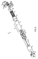
- FIG. 5 depicts a partially-exploded, isometric view of the motorized tube assembly depicted in FIG. 4 .
- FIG. 6 depicts an exploded, isometric view of the motor/controller unit depicted in FIG. 5 .
- FIGS. 7A and 7B depict exploded, isometric views of a motor/controller unit according to an alternative embodiment of the present invention.
- FIGS. 7C , 7 D and 7 E depict isometric views of a motor/controller unit according to another alternative embodiment of the present invention.
- FIG. 8A depicts an exploded, isometric view of the power supply unit depicted in FIGS. 4 and 5 .
- FIGS. 8B and 8C depict an exploded, isometric view of a power supply unit according to an alternative embodiment of the present invention.
- FIGS. 9A and 9B depict exploded, isometric views of a power supply unit according to an alternative embodiment of the present invention.
- FIG. 10 presents a front view of a motorized roller shade, according to an embodiment of the present invention.
- FIG. 11 presents a sectional view along the longitudinal axis of the motorized roller shade depicted in FIG. 10 .
- FIG. 12 presents a front view of a motorized roller shade, according to an embodiment of the present invention.
- FIG. 13 presents a sectional view along the longitudinal axis of the motorized roller shade depicted in FIG. 12 .
- FIG. 14 presents a front view of a motorized roller shade, according to an embodiment of the present invention.
- FIG. 15 presents a sectional view along the longitudinal axis of the motorized roller shade depicted in FIG. 14 .
- FIG. 16 presents an isometric view of a motorized roller shade assembly in accordance with the embodiments depicted in FIGS. 10-15 .
- FIG. 17 presents a method 400 for controlling a motorized roller shade 20 , according to an embodiment of the present invention.
- FIGS. 18 to 25 present operational flow charts illustrating various preferred embodiments of the present invention.
- FIG. 26 is a plan view of a window with a roller shade assembly in accordance with an embodiment of the present invention wherein the shade assembly is deployed in a first position.
- FIG. 27 is a plan view of the window and roller shade assembly depicted in FIG. 26 wherein the roller shade assembly is deployed in a second or closed position.
- FIG. 28 is a plan view of the window or roller shade assembly depicted in FIGS. 26 and 27 wherein the shade assembly is deployed to third or open position.
- FIG. 29 is a perspective or cutaway view of a roller shade assembly illustrating the
- FIG. 30 in an enlarged perspective view of the roller shade assembly depicted in FIG. 29 .
- shade as used herein describes any flexible material, such as a shade, a curtain, a screen, etc., that can be deployed from, and retrieved onto, a storage tube.
- Embodiments of the present invention provide a remote controlled motorized roller shade in which the batteries, DC gear motor, control circuitry are entirely contained within a shade tube that is supported by bearings. Two support shafts are attached to respective mounting brackets, and the bearings rotatably couple the shade tube to each support shaft.
- the output shaft of the DC gear motor is fixed to one of the support shafts, while the DC gear motor housing is mechanically coupled to the shade tube. Accordingly, operation of the DC gear motor causes the motor housing to rotate about the fixed DC gear motor output shaft, which causes the shade tube to rotate about the fixed DC gear motor output shaft as well. Because these embodiments do not require external wiring for power or control, great flexibility in mounting, and re-mounting, the motorized roller shade is provided.
- Encapsulation of the motorization and control components within the shade tube greatly increases the number of duty cycles provided by a single set of batteries and provides a highly efficient roller shade. Additionally, encapsulation advantageously prevents dust and other contaminants from entering the electronics and the drive components.
- the batteries may be mounted outside of the shade tube, and power may be provided to the components located within the shade tube using commutator or slip rings, induction techniques, and the like.
- the external batteries may be replaced by any external source of DC power, such as, for example, an AC/DC power converter, a solar cell, etc.
- FIGS. 1A and 1B depict complementary isometric views of a motorized roller shade assembly 10 having a reverse payout, in accordance with embodiments of the present invention.
- FIGS. 2A and 2B depict complementary isometric views of a motorized roller shade assembly 10 having a standard payout, in accordance with embodiments of the present invention, while FIG. 3 depicts an exploded, isometric view of the motorized roller shade assembly 10 depicted in FIG. 2B .
- motorized roller shade 20 is mounted near the top portion of a window, door, etc., using mounting brackets 5 and 7 .
- motorized roller shade 20 is mounted near the top portion of the window using mounting brackets 15 and 17 , which also support fascia 12 .
- fascia end caps 14 and 16 attach to fascia 12 to conceal motorized roller shade 20 , as well as mounting brackets 15 and 17 .
- motorized roller shade 20 includes a shade 22 and a motorized tube assembly 30 .
- motorized roller shade 20 also includes a bottom bar 28 attached to the bottom of shade 22 .
- bottom bar 28 provides an end-of-travel stop, while in an alternative embodiment, end-of-travel stops 24 and 26 may be provided.
- all of the components necessary to power and control the operation of the motorized roller shade 20 are advantageously located within motorized tube assembly 30 .
- FIGS. 4 and 5 depict isometric views of motorized tube assembly 30 , according to one embodiment of the present invention.
- Motorized tube assembly 30 includes a shade tube 32 , motor/controller unit 40 and battery tube unit 80 .
- the top of shade 22 is attached to the outer surface of shade tube 32 , while motor/controller unit 40 and battery tube unit 80 are located within an inner cavity defined by the inner surface of shade tube 32 .
- FIG. 6 depicts an exploded, isometric view of the motor/controller unit 40 depicted in FIG. 5 .
- the motor/controller unit 40 includes an electrical power connector 42 , a circuit board housing 44 , a DC gear motor 55 that includes a DC motor 50 and an integral motor gear reducing assembly 52 , a mount 54 for the DC gear motor 55 , and a bearing housing 58 .
- the electrical power connector 42 includes a terminal 41 that couples to the power supply unit 80 , and power cables 43 that connect to the circuit board(s) located within the circuit board housing 44 .
- Terminal 41 includes positive and negative connectors that mate with cooperating positive and negative connectors of power supply unit 80 , such as, for example, plug connectors, blade connectors, a coaxial connector, etc. In a preferred embodiment, the positive and negative connectors do not have a preferred orientation.
- the electrical power connector 42 is mechanically coupled to the inner surface of the shade tube 32 using a press fit, an interference fit, a friction fit, a key, adhesive, etc.
- the circuit board housing 44 includes an end cap 45 and a housing body 46 within which at least one circuit board 47 is mounted. In the depicted embodiment, two circuit boards 47 are mounted within the circuit board housing 44 in an orthogonal relationship. Circuit boards 47 generally include all of the supporting circuitry and electronic components necessary to sense and control the operation of the motor 50 , manage and/or condition the power provided by the power supply unit 80 , etc., including, for example, a controller or microcontroller, memory, a wireless receiver, etc.
- the microcontroller is an Microchip 8-bit microcontroller, such as the PIC18F25K20, while the wireless receiver is a Micrel QwikRadio.®. receiver, such as the MICRF219.
- the microcontroller may be coupled to the wireless receiver using a local processor bus, a serial bus, a serial peripheral interface, etc.
- the wireless receiver and microcontroller may be integrated into a single chip, such as, for example, the Zensys ZW0201 Z-Wave Single Chip, etc.
- the antenna for the wireless receiver may mounted to the circuit board or located, generally, inside the circuit board housing 44 .
- the antenna may be located outside the circuit board housing 44 , including, for example, the outer surface of the circuit board housing 44 , the inner surface of the shade tube 32 , the outer surface of the shade tube 32 , the bearing housing 58 , etc.
- the circuit board housing 44 may be mechanically coupled to the inner surface of the shade tube 32 using, for example, a press fit, an interference fit, a friction fit, a key, adhesive, etc.
- a wireless transmitter is also provided, and information relating to the status, performance, etc., of the motorized roller shade 20 may be transmitted periodically to a wireless diagnostic device, or, preferably, in response to a specific query from the wireless diagnostic device.
- the wireless transmitter is a Micrel QwikRadio.®. transmitter, such as the MICRF102.
- a wireless transceiver in which the wireless transmitter and receiver are combined into a single component, may also be included, and in one embodiment, the wireless transceiver is a Micrel RadioWire.®. transceiver, such as the MICRF506.
- the wireless transceiver and microcontroller may be integrated into a single module, such as, for example, the Zensys ZM3102 Z-Wave Module, etc.
- the functionality of the microcontroller, as it relates to the operation of the motorized roller shade 20 is discussed in more detail below.
- the shade tube 32 includes one or more slots to facilitate the transmission of wireless signal energy to the wireless receiver, and from the wireless transmitter, if so equipped.
- the slot may be advantageously matched to the wavelength of the signal.
- the slot is 1 ⁇ 8′′ wide and 21 ⁇ 2′′ long; other dimensions are also contemplated.
- the DC motor 50 is electrically connected to the circuit board 47 , and has an output shaft that is connected to the input shaft of the motor gear reducing assembly 52 .
- the DC motor 50 may also be mechanically coupled to the circuit board housing body 46 using, for example, a press fit, an interference fit, a friction fit, a key, adhesive, mechanical fasteners, etc.
- DC motor 50 and motor gear reducing assembly 52 are provided as a single mechanical package, such as the DC gear motors manufactured by Buhler Motor Inc.
- DC gear motor 55 includes a 24V DC motor and a two-stage planetary gear system with a 40:1 ratio, such as, for example, Buhler DC Gear Motor 1.61.077.423, and is supplied with an average battery voltage of 9.6V.sub.avg provided by an eight D-cell battery stack.
- Buhler DC Gear Motor 1.61.077.423 is supplied with an average battery voltage of 9.6V.sub.avg provided by an eight D-cell battery stack.
- this preferred embodiment offers particular advantages over many alternatives, including, for example, embodiments that include smaller average battery voltages, smaller battery sizes, 12V DC motors, three-stage planetary gear systems, etc.
- the 24V DC gear motor 55 draws a current of about 0.1 A when supplied with a battery voltage of 9.6V.sub.avg.
- a 12V DC gear motor with a similar gear system such as, e.g., Baler DC Gear Motor 1.61.077.413, will draw a current of about 0.2 A when supplied with a battery voltage of 4.8V.sub.avg.
- the 24V DC gear motor supplied with 9.6V.sub.avg advantageously draws about 50% less current than the 12V DC gear motor supplied with 4.8V.sub.avg while producing the same power output.
- the rated voltage of the DC gear motor is much greater than the voltage produced by the batteries, by a factor of two or more, for example, causing the DC motor to operate at a reduced speed and torque rating, which advantageously eliminates undesirable higher frequency noise and draws lower current from the batteries, thereby improving battery life.
- applying a lower-than-rated voltage to the DC gear motor causes the motor to run at a lower-than-rated speed to produce quieter operation and longer battery life as compared to a DC gear motor running at its rated voltage, which draws similar amperage while producing lower run cycle times to produce equivalent mechanical power.
- the 24V DC gear motor running at lower voltages, enhances the cycle life of the battery operated roller shade by about 20% when compared to a 12V DC gear motor using the same battery capacity.
- Alkaline, zinc and lead acid batteries may provide better performance than lithium or nickel batteries, for example.
- four D-cell batteries produce an average battery voltage of about 4.8V.sub.avg
- eight D-cell batteries produce an average battery voltage of about 9.6V.sub.avg
- embodiments that include an eight D-cell battery stack advantageously provide twice as much battery capacity than those embodiments that include a four D-cell battery stack.
- smaller battery sizes such as, e.g., C-cell, AA-cell, etc., offer less capacity than D-cells.
- supplying a 12V DC gear motor with 9.6V.sub.avg increases the motor operating speed, which requires a higher gear ratio in order to provide the same output speed as the 24V DC gear motor discussed above.
- the motor operating speed of the 24V DC gear motor will be about 50% of the motor operating speed of the 12V DC gear motor.
- the higher gear ratio typically requires an additional planetary gear stage, which reduces motor efficiency, increases generated noise, reduces backdrive performance and may require a more complex motor controller. Consequently, those embodiments that include a 24V DC gear motor supplied with 9.6V.sub.avg offer higher efficiencies and less generated noise.
- the shaft 51 of DC motor 50 protrudes into the circuit board housing 44 , and a multi-pole magnet 49 is attached to the end of the motor shaft 51 .
- a magnetic encoder (not shown for clarity) is mounted on the circuit board 47 to sense the rotation of the multi-pole magnet 49 , and outputs a pulse for each pole of the multi-pole magnet 49 that moves past the encoder.
- the multi-pole magnet 49 has eight poles and the gear reducing assembly 52 has a gear ratio of 30:1, so that the magnetic encoder outputs 240 pulses for each revolution of the shade tube 32 .
- the controller advantageously counts these pulses to determine the operational and positional characteristics of the shade, curtain, etc.
- Other types of encoders may also be used, such as optical encoders, mechanical encoders, etc.
- the number of pulses output by the encoder may be associated with a linear displacement of the shade 22 by a distance/pulse conversion factor or a pulse/distance conversion factor.
- this conversion factor is constant regardless of the position of shade 22 .
- the distance/pulse conversion factor is about 0.02 inches/pulse, while the pulse/distance conversion factor is about 48 pulses/inch.
- the outer diameter of the fully-wrapped shade 22 may be used in the calculation.
- the outer diameter of the wrapped shade 22 depends upon the thickness of the shade material.
- the outer diameter of the wrapped shade 22 may be as small as 1.8 inches or as large as 2.5 inches.
- the distance/pulse conversion factor is about 0.03 inches/pulse, while the pulse/distance conversion factor is about 30 pulses/inch.
- any diameter between these two extremes i.e., the outer diameter of the shade tube 32 and the outer diameter of the wrapped shade 22 , may be used. These approximations generate an error between the calculated linear displacement of the shade and the true linear displacement of the shade, so an average or intermediate diameter may preferably reduce the error.
- the conversion factor may be a function of the position of the shade 22 , so that the conversion factor depends upon the calculated linear displacement of the shade 22 .
- the position of the shade 22 is determined and controlled based on the number of pulses that have been detected from a known position of shade 22 . While the open position is preferred, the closed position may also be used as the known position. In order to determine the full range of motion of shade 22 , for example, the shade may be electrically moved to the open position, an accumulated pulse counter may be reset and the shade 22 may then be moved to the closed position, manually and/or electrically. The total number of accumulated pulses represents the limit of travel for the shade, and any desirable intermediate positions may be calculated based on this number.
- an 8 foot shade that moves from the open position to the closed position may generate 3840 pulses, and various intermediate positions of the shade 22 can be advantageously determined, such as, 25% open, 50% open, 75% open, etc. Quite simply, the number of pulses between the open position and the 75% open position would be 960, the number of pulses between the open position and the 50% open position would be 1920, and so on. Controlled movement between these predetermined positions is based on the accumulated pulse count. For example, at the 50% open position, this 8 foot shade would have an accumulated pulse count of 1920, and controlled movement to the 75% open position would require an increase in the accumulated pulse count to 2880.
- movement of the shade 22 is determined and controlled based on accumulating the number of pulses detected since the shade 22 was deployed in the known position.
- An average number of pulses/inch may be calculated based on the total number of pulses and the length of shade 22 , and an approximate linear displacement of the shade 22 can be calculated based on the number of pulses accumulated over a given time period.
- the average number of pulses/inch is 40, so movement of the shade 22 about 2 inches would generate about 80 pulses.
- Positional errors are advantageously eliminated by resetting the accumulated pulse counter to zero whenever the shade 22 is moved to the known position.
- a mount 54 supports the DC gear motor 55 , and may be mechanically coupled to the inner surface of the shade tube 32 .
- the outer surface of the mount 54 and the inner surface of the shade tube 32 are smooth, and the mechanical coupling is a press fit, an interference fit, a friction fit, etc.
- the outer surface of the mount 54 includes several raised longitudinal protrusions that mate with cooperating longitudinal recesses in the inner surface of the shade tube 32 .
- the mechanical coupling is keyed; a combination of these methods is also contemplated. If the frictional resistance is small enough, the motor/controller unit 40 may be removed from the shade tube 32 for inspection or repair; in other embodiments, the motor/controller unit 40 may be permanently secured within the shade tube 32 using adhesives, etc.
- the circuit board housing 44 and the mount 54 may be mechanically coupled to the inner surface of the shade tube 32 . Accordingly, at least three different embodiments are contemplated by the present invention. In one embodiment, the circuit board housing 44 and the mount 54 are both mechanically coupled to the inner surface of the shade tube 32 . In another embodiment, only the circuit board housing 44 is mechanically coupled to the inner surface of the shade tube 32 . In a further embodiment, only the mount 54 is mechanically coupled to the inner surface of the shade tube 32 .
- the output shaft of the DC gear motor 55 is fixed to the support shaft 60 , either directly (not shown for clarity) or through an intermediate shaft 62 .
- support shaft 60 is attached to a mounting bracket that prevents the support shaft 60 from rotating. Because (a) the output shaft of the DC gear motor 55 is coupled to the support shaft 60 which is fixed to the mounting bracket, and (b) the DC gear motor 55 is mechanically-coupled to the shade tube, operation of the DC gear motor 55 causes the DC gear motor 55 to rotate about the fixed output shaft, which causes the shade tube 32 to rotate about the fixed output shaft as well.
- Bearing housing 58 includes one or more bearings 64 that are rotatably coupled to the support shaft 60 .
- bearing housing 58 includes two rolling element bearings, such as, for example, spherical ball bearings; each outer race is attached to the bearing housing 58 , while each inner race is attached to the support shaft 60 .
- two ball bearings are spaced about 3 ⁇ 8′′ apart giving a total support land of about 0.8′′ or 20 mm; in an alternative embodiment, the intra-bearing spacing is about twice the diameter of support shaft 60 .
- Other types of low-friction bearings are also contemplated by the present invention.
- the motor/controller unit 40 may also include counterbalancing.
- motor/controller unit 40 includes a fixed perch 56 attached to intermediate shaft 62 .
- mount 54 functions as a rotating perch
- a counterbalance spring 63 (not shown in FIG. 5 for clarity; shown in FIG. 6 ) is attached to the rotating perch 54 and the fixed perch 56 .
- the intermediate shaft 62 may be hexagonal in shape to facilitate mounting of the fixed perch 56 . Preloading the counterbalance spring advantageously improves the performance of the motorized roller shade 20 .
- FIGS. 7A and 7B depict exploded, isometric views of a motor/controller unit 40 according to an alternative embodiment of the present invention.
- housing 67 contains the major components of the motor/controller unit 40 , including DC gear motor 55 (e.g., DC motor 50 and motor gear reducing assembly 52 ), one or more circuit boards 47 with the supporting circuitry and electronic components described above, and at least one bearing 64 .
- the output shaft 53 of the DC gear motor 55 is fixedly-attached to the support shaft 60 , while the inner race of bearing 64 is rotatably-attached support shaft 60 .
- at least one power spring 65 is disposed within housing 67 , and is rotatably-attached to support shaft 60 .
- Housing 67 may be formed from two complementary sections, fixed or removably joined by one or more screws, rivets, etc.
- FIGS. 7C , 7 D and 7 E depict isometric views of a motor/controller unit 40 according to another alternative embodiment of the present invention.
- housing 68 contains the DC gear motor 55 (e.g., DC motor 50 and motor gear reducing assembly 52 ), one or more circuit boards 47 with the supporting circuitry and electronic components described above, while housing 69 includes at least one bearing 64 .
- Housings 68 and 69 may be attachable to one another, either removably or permanently.
- the output shaft 53 of the DC gear motor 55 is fixedly-attached to the support shaft 60 , while the inner race of bearing 64 is rotatably-attached support shaft 60 .
- At least one power spring 65 is disposed within housing 69 , and is rotatably-attached to support shaft 60 . While the depicted embodiment includes two power springs 65 , three (or more) power springs 65 may be used, depending on the counterbalance force required, the available space within shade tube 32 , etc. Housings 68 and 69 may be formed from two complementary sections, fixed or removably joined by one or more screws, rivets, etc.
- FIG. 8A depicts an exploded, isometric view of the power supply unit 80 depicted in FIGS. 4 and 5 .
- the power supply unit 80 includes a battery tube 82 , an outer end cap 86 , and a inner end cap 84 .
- the outer end cap 86 includes one or more bearings 90 that are rotatably coupled to a support shaft 88 .
- outer end cap 86 includes two low-friction rolling element bearings, such as, for example, spherical ball bearings, separated by a spacer 91 ; each outer race is attached to the outer end cap 86 , while each inner race is attached to the support shaft 88 .
- Other types of low-friction bearings are also contemplated by the present invention.
- bearings 86 are simply bearing surfaces, preferably low-friction bearing surfaces, while in another alternative embodiment, support shaft 88 is fixedly attached to the outer end cap 86 , and the external shade support bracket provides the bearing surface for the support shaft 88 .
- the outer end cap 86 is removable and the inner cap 84 is fixed.
- the inner end cap 84 may be removable and the outer end cap 86 may be fixed, both end caps may be removable, etc.
- the removable end cap(s) may be threaded, slotted, etc.
- the outer end cap 86 also includes a positive terminal that is coupled to the battery tube 82 .
- the inner end cap 84 includes a positive terminal coupled to the battery tube 82 , and a negative terminal coupled to a conduction spring 85 .
- the positive terminal of the outer end cap 86 is electrically coupled to the positive terminal of one of the batteries in the battery stack 92
- the negative terminal of the inner end cap 84 is electrically coupled to the negative terminal of another one of the batteries in the battery stack 92 .
- the positive and negative terminals may be reversed, so that the conduction spring 85 contacts the positive terminal of one of the batteries in the battery stack 92 , etc.
- the outer end cap 86 and the inner end cap 84 are mechanically coupled to the inner surface of the shade tube 32 .
- the outer surface of the mount 84 and the inner surface of the shade tube 32 are smooth, and the mechanical coupling is a press fit, an interference fit, a friction fit, etc.
- the outer surface of the mount 84 includes several raised longitudinal protrusions that mate with cooperating longitudinal recesses in the inner surface of the shade tube 32 .
- the mechanical coupling is keyed; a combination of these methods is also contemplated.
- the frictional resistance should be small enough such that the power supply unit 80 can be removed from the shade tube 32 for inspection, repair and battery replacement.
- the battery stack 92 includes eight D-cell batteries connected in series to produce an average battery stack voltage of 9.6V.sub.avg.
- Other battery sizes, as well as other DC power sources disposable within battery tube 82 are also contemplated by the present invention.
- the electrical connector 42 is fitted within the inner cavity of shade tube 32 to a predetermined location; power cables 43 has a length sufficient to permit the remaining sections of the motor/controller unit 40 to remain outside the shade tube 32 until the electrical connector 42 is properly seated.
- the remaining sections of the motor/controller unit 40 are then fitted within the inner cavity of shade tube 32 , such that the bearing housing 58 is approximately flush with the end of the shade tube 32 .
- the power supply unit 80 is then inserted into the opposite end until the positive and negative terminals of the inner end cap 84 engage the terminal 41 of the electrical connector 42 .
- the outer end cap 86 should be approximately flush with end of the shade tube 32 .
- the outer end cap 86 is mechanically coupled to the inner surface of the shade tube 32 using a press fit, interference fit, an interference member, such as O-ring 89 , etc., while the inner end cap 81 is not mechanically coupled to the inner surface of the shade tube 32 .
- the shade tube 32 functions as the battery tube 82 , and the battery stack 92 is simply inserted directly into shade tube 32 until one end of the battery stack 92 abuts the inner end cap 84 .
- the positive terminal of the outer end cap 86 is coupled to the positive terminal of the inner end cap 84 using a wire, foil strip, trace, etc.
- the positive and negative terminals may be reversed, so that the respective negative terminals are coupled.
- the batteries may be mounted outside of the shade tube, and power may be provided to the components located within the shade tube using commutator or slip rings, induction techniques, and the like.
- the external batteries may be replaced by any external source of DC power, such as, for example, an AC/DC power converter, a solar cell, etc.
- FIGS. 9A and 9B depict exploded, isometric views of a power supply unit according to an alternative embodiment of the present invention.
- power supply unit 80 includes a housing 95 with one or more bearings 90 that are rotatably coupled to a support shaft 88 , a power coupling 93 to receive power from an external power source, and positive and negative terminals to engage the electrical connector 42 .
- Power cables 97 (shown in phantom for clarity) extend from the power coupling 93 , through a hollow central portion of support shaft 88 , to an external DC power source.
- housing 95 includes two low-friction rolling element bearings 90 , such as, for example, spherical ball bearings; each outer race is attached to the housing 95 , while each inner race is attached to the support shaft 88 .
- low-friction rolling element bearings 90 such as, for example, spherical ball bearings
- Housing 95 may be formed from two complementary sections, fixed or removably joined by one or more screws, rivets, etc.
- the support shafts 88 are slidingly-attached to the inner race of ball bearings 90 so that the support shafts 88 may be displaced along the rotational axis of the shade tube 32 .
- This adjustability advantageously allows an installer to precisely attach the end of the support shafts 88 to the respective mounting bracket by adjusting the length of the exposed portion of the support shafts 88 .
- outer end cap 86 and housing 95 may provide approximately 0.5′′ of longitudinal movement for the support shafts 88 .
- mounting brackets 5 , 7 , 15 and 17 are embossed so that the protruding portion of the mounting bracket will only contact the inner race of bearings 64 and 90 and will not rub against the edge of the shade or the shade tube 32 if the motorized roller shade 20 is installed incorrectly.
- the bearings may accommodate up to 0.125′′ of misalignment due to installation errors without a significant reduction in battery life.
- the microcontroller receives control signals from a wired remote control. These control signals may be provided to the microcontroller in various ways, including, for example, over power cables 97 , over additional signal lines that are accommodated by power coupling 93 , over additional signal lines that are accommodated by a control signal coupling (not shown in FIGS. 9 A,B for clarity), etc.
- FIGS. 10-16 Various additional embodiments of the present invention are presented in FIGS. 10-16 .
- FIGS. 10 and 11 depict an alternative embodiment of the present invention without counterbalancing;
- FIG. 10 presents a front view of a motorized roller shade 120
- FIG. 11 presents a sectional view along the longitudinal axis of the motorized roller shade 120 .
- the output shaft of the DC gear motor 150 is attached to the support shaft 160 , and an intermediate shaft is not included.
- FIGS. 12 and 13 depict an alternative embodiment of the present invention with counterbalancing;
- FIG. 12 presents a front view of a motorized roller shade 220
- FIG. 13 presents a sectional view along the longitudinal axis of the motorized roller shade 220 .
- FIGS. 14 and 15 depict an alternative embodiment of the present invention with counterbalancing;
- FIG. 14 presents a front view of a motorized roller shade 320
- FIG. 15 presents a sectional view along the longitudinal axis of the motorized roller shade 320 .
- the output shaft of the DC gear motor 350 is attached to the intermediate shaft 362 .
- a power spring 390 couples the intermediate shaft 362 to the inner surface of the shade tube 332 .
- FIG. 16 presents an isometric view of a motorized roller shade assemblies 120 , 220 , 320 in accordance with the embodiments depicted in FIGS. 10-15 .
- Motorized roller shade 20 may be controlled manually and/or remotely using a wireless or wired remote control.
- the microcontroller executes instructions stored in memory that sense and control the motion of DC gear motor 55 , decode and execute commands received from the remote control, monitor the power supply voltage, etc. More than one remote control may be used with a single motorized roller shade 20 , and a single remote control may be used with more than one motorized roller shade 20 .
- FIG. 17 presents a method 400 for controlling a motorized roller shade 20 , according to an embodiment of the present invention.
- method 400 includes a manual control portion 402 and a remote control portion 404 .
- method 400 includes the manual control portion 402
- method 400 includes the remote control portion 404
- method 400 includes both the manual control portion 402 and the remote control portion 404 .
- a manual movement of the shade 22 is detected ( 410 ), a displacement associated with the manual movement is determined ( 420 ), and, if the displacement is less than a maximum displacement, the shade 22 is moved ( 430 ) to a different position by rotating the shade tube 32 using the DC gear motor 55 .
- the microcontroller detects a manual downward movement of the shade 22 by monitoring a reed switch, while in an alternative embodiment, the microcontroller simply monitors the encoder.
- the microcontroller begins to count the encoder pulses generated by the rotation of the shade tube 32 relative to the fixed motor shaft 51 .
- the encoder pulses cease, the downward movement has stopped, and the displacement of the shade 22 is determined and then compared to a maximum displacement.
- the shade displacement is simply the total number of encoder pulses received by the microcontroller, and the maximum displacement is a predetermined number of encoder pulses.
- the microcontroller converts the encoder pulses to a linear distance, and then compares the calculated linear distance to a maximum displacement, such as 2 inches.
- the maximum number of encoder pulses is 80, which may represent approximately 2 inches of linear shade movement in certain embodiments. If the total number of encoder pulses received by the microcontroller is greater than or equal to 80, then the microcontroller does not energize the DC gear motor 55 and the shade 22 simply remains at the new position. On the other hand, if the total number of encoder pulses received by the microcontroller is less than 80, then the microcontroller moves the shade 22 to a different position by energizing the DC gear motor 55 to rotate the shade tube 32 . After the microcontroller determines that the shade 22 has reached the different position, the DC gear motor 55 is de-energized.
- the microcontroller maintains the current position of the shade 22 by accumulating the number of encoder pulses since the shade 22 was deployed in the known position.
- the known (e.g., open) position has an accumulated pulse count of 0, and the various intermediate positions each have an associated accumulated pulse count, such as 960, 1920, etc.
- the microcontroller increments the accumulated pulse counter, and when the shade 22 moves in the upward direction, the microcontroller decrements the accumulated pulse counter.
- Each pulse received from the encoder increments or decrements the accumulated pulse counter by one count.
- the microcontroller may convert each pulse count to a linear distance, and perform these calculations in units of inches, millimeters, etc.
- limited manual downward movement of the shade 22 causes the microcontroller to move the shade to a position located directly above the current position, such as 25% open, 50% open, 75% open, 100% open, etc.
- a position located directly above the current position such as 25% open, 50% open, 75% open, 100% open, etc.
- Each of these predetermined positions has an associated accumulated pulse count, and the microcontroller determines that the shade 22 has reached the different position by comparing the value in the accumulated pulse counter to the accumulated pulse count of the predetermined position; when the accumulated pulse counter equals the predetermined position accumulated pulse count, the shade 22 has reached the different position.
- ⁇ ⁇ ⁇ ⁇ ⁇ ⁇ ⁇ ⁇ ⁇ ⁇ ⁇ ⁇ ⁇ ⁇ ⁇ ⁇ ⁇ ⁇ ⁇ ⁇ ⁇ ⁇ ⁇ ⁇ ⁇ ⁇ ⁇ ⁇ ⁇ ⁇ ⁇ ⁇ ⁇ ⁇ ⁇ ⁇ ⁇ ⁇ ⁇ ⁇ ⁇ ⁇ ⁇ ⁇ ⁇ ⁇ ⁇ ⁇ ⁇ ⁇ ⁇ ⁇ ⁇ ⁇ ⁇ ⁇ ⁇ ⁇ ⁇ ⁇ ⁇ ⁇ ⁇ ⁇ ⁇ ⁇ ⁇ ⁇ ⁇ ⁇ ⁇ ⁇ ⁇ ⁇ ⁇ ⁇ ⁇ ⁇ ⁇ ⁇ ⁇ ⁇ ⁇ ⁇ ⁇ ⁇ ⁇ ⁇ ⁇ ⁇ ⁇ ⁇ ⁇ ⁇ ⁇ ⁇ ⁇ ⁇ ⁇ ⁇ ⁇ ⁇ ⁇ ⁇ ⁇ ⁇ ⁇ ⁇ ⁇ ⁇ ⁇ ⁇ ⁇ ⁇ ⁇ ⁇ ⁇ ⁇ ⁇ ⁇ ⁇ ⁇ ⁇ ⁇ ⁇ ⁇
- Manual upward movement of the shade 22 may be detected and measured using an encoder that senses direction as well as rotation, such as, for example, an incremental rotary encoder, a relative rotary encoder, a quadrature encoder, etc.
- limited upward movement of the shade 22 causes the microcontroller to move the shade to a position located above the current position, etc.
- a command is received ( 440 ) from a remote control, and the shade 22 is moved ( 450 ) to a position associated with the command.
- the remote control is a wireless transmitter that has several shade position buttons that are associated with various commands to move the shade 22 to different positions.
- the buttons activate switches that may be electro-mechanical, such as, for example, momentary contact switches, etc, electrical, such as, for example, a touch pad, a touch screen, etc.
- the wireless transmitter sends a message to the motorized roller shade 20 that includes a transmitter identifier and a command associated with the activated button.
- the remote control is pre-programmed such that each shade position button will command the shade to move to a predetermined position.
- remote control functionality may be embodied within a computer program, and this program may be advantageously hosted on a wireless device, such as an iPhone.
- the wireless device may communicate directly with the motorized roller shade 20 , or through an intermediate gateway, bridge, router, base station, etc.
- the motorized roller shade 20 includes a wireless receiver that receives, decodes and sends the message to the microcontroller for further processing.
- the message may be stored within the wireless transmitter and then sent to the microcontroller immediately after decoding, or the message may be sent to the microcontroller periodically, e.g., upon request by the microcontroller, etc.
- One preferred wireless protocol is the Z-Wave Protocol, although other wireless communication protocols are contemplated by the present invention.
- the microcontroller interprets the command and sends an appropriate control signal to the DC gear motor 55 to move the shade in accordance with the command.
- the DC gear motor 55 and shade tube 32 rotate together, which either extends or retracts the shade 22 .
- the message may be validated prior to moving the shade, and the command may be used during programming to set a predetermined deployment of the shade.
- the microcontroller decrements the accumulated pulse counter by one count every time a pulse is received from the encoder, and when the accumulated pulse counter reaches 1920, the microcontroller de-energizes the DC gear motor 55 , which stops the shade 22 at the 50% open position. In one embodiment, if a different command is received while the shade 22 is moving, the microcontroller may stop the movement of the shade 22 .
- the microcontroller may de-energize the DC gear motor 55 to stop the movement of the shade 22 .
- the microcontroller may de-energize the DC gear motor 55 to stop the movement of the shade 22 .
- Other permutations are also contemplated by the present invention, such as moving the shade 22 to the predetermined position associated with the second command, etc.
- a command to move the shade to the 100% open position resets the accumulated pulse counter to 0, and the microcontroller de-energizes the DC gear motor 55 when the encoder pulses cease.
- an end-of-travel stop such as bottom bar 28 , stops 24 and 26 , and the like, engage corresponding structure on the mounting brackets when the shade 22 has been retracted to the 100% open position. This physical engagement stops the rotation of the shade tube 32 and stalls the DC gear motor 55 .
- the microcontroller senses that the encoder has stopped sending pulses, e.g., for one second, and de-energizes the DC gear motor 55 .
- the microcontroller may check an end-of-travel pulse count in order to prevent the shade 22 from extending past a preset limit.
- the movement of the shade 22 may simply be determined using relative pulse counts. For example, if the current position of the shade 22 is 100% open, and a command to move the shade 22 to the 50% open position is received, the microcontroller may simply energize the DC gear motor 55 until a certain number of pulses have been received, by the microcontroller, from the encoder. In other words, the pulse count associated with predetermined position is relative to the predetermined position located directly above or below, rather than the known position.
- FIGS. 20 to 24 For the preferred embodiment, programming a motorized roller shade 20 to accept commands from a particular remote control depicted in FIGS. 18 and 25 , while programming or teaching the motorized roller shade 20 to deploy and retract the shade 22 to various preset or predetermined positions, such as open, closed, 25% open, 50% open, 75% open, etc., is depicted in FIGS. 20 to 24 .
- Other programming methodologies are also contemplated by the present invention.
- a brake may be applied to the motorized roller shade 20 to stop the movement of the shade 22 , as well as to prevent undesirable rotation or drift after the shade 22 has been moved to a new position.
- the microcontroller connects the positive terminal of the DC gear motor 55 to the negative terminal of DC gear motor 55 , using one or more electro-mechanical switches, power FETS, MOSFETS, etc., to apply the brake.
- the positive and negative terminals of the DC gear motor 55 may be connected to ground, which may advantageously draw negligible current. In a negative ground system, the negative terminal of the DC gear motor 55 is already connected to ground, so the microcontroller only needs to connect the positive terminal of the DC gear motor 55 to ground. Conversely, in a positive ground system, the positive terminal of the DC gear motor 55 is already connected to ground, so the microcontroller only needs to connect the negative terminal of the DC gear motor 55 to ground.
- any rotation of the shade tube 32 will cause the DC gear motor 55 to generate a voltage, or counter electromotive force, which is fed back into the DC gear motor 55 to produce a dynamic braking effect.
- Other braking mechanisms are also contemplated by the present invention, such as friction brakes, electro-mechanical brakes, electro-magnetic brakes, permanent-magnet single-face brakes, etc.
- the microcontroller releases the brake after a manual movement of the shade 22 is detected, as well as prior to energizing the DC gear motor 55 to move the shade 22 .
- the positive or negative terminal of the DC gear motor 55 is connected to ground to apply the maximum amount of braking force and bring the shade 22 to a complete stop.
- the microcontroller then connects the positive and negative terminals of the DC gear motor 55 together via a low-value resistor, using an additional MOSFET, for example, to apply a reduced amount of braking force to the shade 22 , which prevents the shade 22 from drifting but allows the user to tug the shade 22 over long displacements without significant resistance.
- the brake is not released after the manual movement of the shade is detected in order to provide a small amount of resistance during the manual movement.
- FIGS. 18 to 25 present operational flow charts illustrating preferred embodiments of the present invention.
- the functionality illustrated therein is implemented, generally, as instructions executed by the microcontroller.
- FIG. 18 depicts a Main Loop 500 that includes a manual control operational flow path, a remote control operational flow path, and a combined operational flow path.
- Main Loop 500 exits to various subroutines, including subroutine “TugMove” 600 ( FIG. 19 ), subroutine “Move25” 700 ( FIG. 20 ), subroutine “Move50” 800 ( FIG. 21 ), subroutine “Move75” 900 ( FIG. 22 ), subroutine “MoveUp” 1000 ( FIG. 23 ), subroutine “MoveDown” 1100 ( FIG. 24 ), which return control to Main Loop 500 .
- Subroutine “Power-Up” 1200 ( FIG. 25 ) is executed upon power up, and then exits to Main Loop 500 .
- the shade tube 32 is an aluminum tube having an outer diameter of 1.750 inches and a wall thickness of 0.062 inches.
- Bearings 64 and 90 each include two steel ball bearings, 30 mm OD.times.10 mm ID.times.9 mm wide, that are spaced 0.250′′ apart. In other words, a total of four ball bearings, two at each end of the motorized roller shade 20 , are provided.
- the DC gear motor 55 is a Buhler DC gear motor 1.61.077.423, as discussed above.
- the battery tube 82 accommodates 6 to 8 D-cell alkaline batteries, and supplies voltages ranges from 6 V to 12 V, depending on the number of batteries, shelf life, cycles of the shade tube assembly, etc.
- the shade 22 is a flexible fabric that is 34 inches wide, 60 inches long, 0.030 inches thick and weighs 0.100 lbs/sq. ft, such as, for example, Phifer Q89 Wicker/Brownstone.
- An aluminum circularly-shaped curtain bar 28 having a diameter of 0.5 inches, is attached to the shade 22 to provide taughtness as well as an end-of-travel stop.
- the counterbalance spring 63 is a clock spring that provides 1.0 to 1.5 in-lb of counterbalance torque to the shade 22 after it has reached 58 inches of downward displacement.
- the current drawn by the Buihler DC gear motor ranges between 0.06 and 0.12 amps, depending on friction.
- FIGS. 26-28 a schematic view of a window, generally designated 1200 is illustrated, wherein the window 1200 has a blind or shade assembly 1202 mounted thereto having a shade or blind 1204 .
- the blind or shade assembly 1202 has the shade or blind 1024 deployed in a first position whereas FIG. 27 depicts the shade or blind assembly 1202 wherein the shade or blind 1204 is fully deployed to the closed position, covering the window 1200 .
- FIG. 28 depicts the shade or blind assembly 1202 wherein the shade or blind 1204 is in a third, fully open position.
- FIGS. 29 and 30 The aforementioned figures and corresponding positions will be discussed further in connection with FIGS. 29 and 30 .
- the roller shade or blind assembly 1202 is depicted in accordance with the embodiments of the present invention described herein.
- the roller or shade assembly 1202 includes a motor (not shown) having an output shaft 1206 extending therefrom.
- a Hall Effect magnet wheel 1208 is mounted to said output shaft 1206 .
- the roller shade or blind assembly 1202 also comprises a Hall Effect sensor as part of a printed circuit board 1210 .
- the roller shade or blind assembly 1202 may employ a chopper wheel wherein an optical encoder is mounted to the printed circuit board 1210 instead of the above-discussed Hall Effect magnet wheel and sensor.
- the roller shade or blind assembly 1202 may alternatively employ a magnetic reed witch or a potentiometer.
- the roller shade or blind assembly 1202 includes a microprocessor (not shown) as previously discussed, which is mounted to a second printed circuit board 1212 .
- the microprocessor is electrically connected to the power supply and the first printed circuit board 1210 .
- the shade or blind 1204 will be able to move or translate to a predetermined position.
- One preferred distance is about 12 inches (30.5 cm) but it can be any desired distance/position in the path of travel of the shade or blind 1204 , for example as illustrated in FIG. 26 .
- the aforementioned translations of the shade or blind 1204 may be automatic from a time out command after energizing the power supply or a manual movement of the shade or blind 1204 , such as a tug, or a depression of a button on a remote transmitter.
- control unit may proceed to time out and translate of move the shade or blind 1204 to a third or fully open position as depicted in FIG. 28 .
- the aforementioned last movement or translation is typically automatic by means of a countdown timer but alternatively could be initiated by a transmitter or a short tug on the shade or blind 1204 .
- the described setup would likely be performed each time the power supply is energized and in said embodiment, may occur automatically if for some reason the Hall Effect sensor 1210 lost count causing a hard stop.
- the upper limit hard stop as previously mentioned, at the top of the roller shade travel is utilized to re-sync the encoder count by detecting the upper travel limit.
- the use of “absolute encoders” is permitted as well as “non-absolute encoders” which must be recalibrated or re-synced to an encoder zero position as desired, in this case the hard stop at the top. Over time, an encoder might become slightly out of sync with the actual shade position causing the shade assembly to not function correctly or as desired. This described occurrence can easily happen when the reed switch is falsely triggered by the encoder magnet rocking or oscillating due to motor and fabric and spring working against each other at some position of travel.
- the number of cycles is an arbitrary number and can be any desired or needed value.
- the aforementioned syncing process is preferred as it is undesireable to take an energy hit by stalling the motor every time the blind or shade 1204 is retracted all the way and it is undesirable to introduce noise. e.g., clank, etc., by having the bottom bar of the blind or shade, for example, hit the hard stop every time the blind or shade 1204 is refracted.
- the end user may use a lower starting position for the blind or shade 1204 as one of the intermediate positions. So, for instance, if the end user were to tug on the blind or shade 1204 to propel it to the top, the end user may alternatively stop at an intermediate position to allow for the blind or shade 1204 to be more easily accessible. Since the intermediate positions are programmable, an end user may set the upper height to whatever “artificial top” desired or preferred.
Abstract
Description
Claims (24)
Priority Applications (5)
| Application Number | Priority Date | Filing Date | Title |
|---|---|---|---|
| US14/018,823 US8947027B2 (en) | 2010-02-23 | 2013-09-05 | High efficiency roller shade and method for setting artificial stops |
| US14/072,975 US9152032B2 (en) | 2010-02-23 | 2013-11-06 | High efficiency motorized roller screen and method of operation |
| US14/562,946 US9410369B2 (en) | 2010-02-23 | 2014-12-08 | High efficiency roller shade and method for setting artificial stops |
| US15/203,293 US9725948B2 (en) | 2010-02-23 | 2016-07-06 | High efficiency roller shade and method for setting artificial stops |
| US15/633,895 US10246938B2 (en) | 2010-02-23 | 2017-06-27 | High efficiency roller shade and method for setting artificial stops |
Applications Claiming Priority (3)
| Application Number | Priority Date | Filing Date | Title |
|---|---|---|---|
| US12/711,193 US8368328B2 (en) | 2010-02-23 | 2010-02-23 | Method for operating a motorized roller shade |
| US13/653,451 US8575872B2 (en) | 2010-02-23 | 2012-10-17 | High efficiency roller shade and method for setting artificial stops |
| US14/018,823 US8947027B2 (en) | 2010-02-23 | 2013-09-05 | High efficiency roller shade and method for setting artificial stops |
Related Parent Applications (1)
| Application Number | Title | Priority Date | Filing Date |
|---|---|---|---|
| US13/653,451 Continuation US8575872B2 (en) | 2010-02-23 | 2012-10-17 | High efficiency roller shade and method for setting artificial stops |
Related Child Applications (2)
| Application Number | Title | Priority Date | Filing Date |
|---|---|---|---|
| US14/072,975 Continuation-In-Part US9152032B2 (en) | 2010-02-23 | 2013-11-06 | High efficiency motorized roller screen and method of operation |
| US14/562,946 Continuation US9410369B2 (en) | 2010-02-23 | 2014-12-08 | High efficiency roller shade and method for setting artificial stops |
Publications (2)
| Publication Number | Publication Date |
|---|---|
| US20140008027A1 US20140008027A1 (en) | 2014-01-09 |
| US8947027B2 true US8947027B2 (en) | 2015-02-03 |
Family
ID=48135418
Family Applications (5)
| Application Number | Title | Priority Date | Filing Date |
|---|---|---|---|
| US13/653,451 Expired - Fee Related US8575872B2 (en) | 2010-02-23 | 2012-10-17 | High efficiency roller shade and method for setting artificial stops |
| US14/018,823 Active US8947027B2 (en) | 2010-02-23 | 2013-09-05 | High efficiency roller shade and method for setting artificial stops |
| US14/562,946 Active 2030-05-22 US9410369B2 (en) | 2010-02-23 | 2014-12-08 | High efficiency roller shade and method for setting artificial stops |
| US15/203,293 Expired - Fee Related US9725948B2 (en) | 2010-02-23 | 2016-07-06 | High efficiency roller shade and method for setting artificial stops |
| US15/633,895 Active US10246938B2 (en) | 2010-02-23 | 2017-06-27 | High efficiency roller shade and method for setting artificial stops |
Family Applications Before (1)
| Application Number | Title | Priority Date | Filing Date |
|---|---|---|---|
| US13/653,451 Expired - Fee Related US8575872B2 (en) | 2010-02-23 | 2012-10-17 | High efficiency roller shade and method for setting artificial stops |
Family Applications After (3)
| Application Number | Title | Priority Date | Filing Date |
|---|---|---|---|
| US14/562,946 Active 2030-05-22 US9410369B2 (en) | 2010-02-23 | 2014-12-08 | High efficiency roller shade and method for setting artificial stops |
| US15/203,293 Expired - Fee Related US9725948B2 (en) | 2010-02-23 | 2016-07-06 | High efficiency roller shade and method for setting artificial stops |
| US15/633,895 Active US10246938B2 (en) | 2010-02-23 | 2017-06-27 | High efficiency roller shade and method for setting artificial stops |
Country Status (1)
| Country | Link |
|---|---|
| US (5) | US8575872B2 (en) |
Cited By (21)
| Publication number | Priority date | Publication date | Assignee | Title |
|---|---|---|---|---|
| US9334688B2 (en) | 2011-10-03 | 2016-05-10 | Hunter Douglas Inc. | Control of architectural opening coverings |
| US9644424B2 (en) | 2015-10-12 | 2017-05-09 | Crestron Electronics, Inc. | Touch hem bar control |
| US9702189B2 (en) * | 2015-10-01 | 2017-07-11 | Calendar Enterprises Co., Ltd. | Energy saving apparatus for electric roller shutter |
| US9790739B2 (en) | 2010-05-28 | 2017-10-17 | Hunter Douglas Inc. | Architectural opening coverings powered by rotary motors |
| US20180106100A1 (en) * | 2016-10-19 | 2018-04-19 | Hunter Douglas, Inc. | Dual mode architectural structure covering |
| US20180305979A1 (en) * | 2017-04-19 | 2018-10-25 | Tti (Macao Commercial Offshore) Limited | Motorized window covering having powered modules |
| US10221622B2 (en) | 2015-09-08 | 2019-03-05 | Crestron Electronics, Inc. | Roller shade with a pretensioned spring and method for pretensioning the spring |
| US10227821B2 (en) * | 2015-12-15 | 2019-03-12 | Vkr Holding A/S | Electrically and manually adjustable screening device and method for screening a window |
| US10590701B2 (en) | 2013-03-14 | 2020-03-17 | Hunter Douglas Inc. | Methods and apparatus to control an architectural opening covering assembly |
| US10648232B2 (en) | 2012-10-03 | 2020-05-12 | Hunter Douglas Inc. | Methods and apparatus to control an architectural opening covering assembly |
| US10676989B2 (en) | 2016-02-19 | 2020-06-09 | Hunter Douglas Inc. | Motor assembly for an architectural covering |
| US10684542B2 (en) | 2017-05-16 | 2020-06-16 | Draper, Inc. | Projection screen system |
| US10738530B2 (en) | 2018-01-16 | 2020-08-11 | Crestron Electronics, Inc. | Motor pretensioned roller shade |
| US10851587B2 (en) | 2016-10-19 | 2020-12-01 | Hunter Douglas Inc. | Motor assemblies for architectural coverings |
| US10941615B2 (en) | 2009-01-14 | 2021-03-09 | Hunter Douglas, Inc. | Noise dampening motor drive system for retractable covering for architectural openings |
| US11002071B2 (en) | 2018-03-29 | 2021-05-11 | Crestron Electronics, Inc. | Architectural roller shade housing with adjustable battery compartment |
| US11072976B2 (en) | 2017-02-06 | 2021-07-27 | Hunter Douglas, Inc. | Methods and apparatus to reduce noise in motor assemblies |
| US11111907B1 (en) | 2018-05-13 | 2021-09-07 | Tpe Midstream Llc | Fluid transfer and depressurization system |
| US11396772B2 (en) | 2019-12-10 | 2022-07-26 | Crestron Electronics, Inc. | Obstacle and pulling detection in a clutch based roller shade |
| US11486198B2 (en) | 2019-04-19 | 2022-11-01 | Hunter Douglas Inc. | Motor assemblies for architectural coverings |
| US11591850B2 (en) | 2019-11-01 | 2023-02-28 | Crestron Electronics, Inc. | Capacitive touch fabric and system and method for shade control via the capacitive touch fabric |
Families Citing this family (36)
| Publication number | Priority date | Publication date | Assignee | Title |
|---|---|---|---|---|
| US8919419B2 (en) * | 2008-12-04 | 2014-12-30 | Qmotion Incorporated | Counterbalanced motorized shade roll system and method |
| US8659246B2 (en) | 2010-02-23 | 2014-02-25 | Homerun Holdings Corporation | High efficiency roller shade |
| US8575872B2 (en) | 2010-02-23 | 2013-11-05 | Homerun Holdings Corporation | High efficiency roller shade and method for setting artificial stops |
| US9194179B2 (en) | 2010-02-23 | 2015-11-24 | Qmotion Incorporated | Motorized shade with the transmission wire passing through the support shaft |
| US9249623B2 (en) | 2010-02-23 | 2016-02-02 | Qmotion Incorporated | Low-power architectural covering |
| FR2992142B1 (en) * | 2012-06-13 | 2014-07-11 | Somfy Sas | ELEMENT FOR SUPPORTING A BATTERY IN A WINDOW TUBE OF A DOMOTIC SCREEN |
| US10934773B2 (en) | 2012-06-13 | 2021-03-02 | Somfy Activites Sa | Motorized manoeuvring device intended to manoeuvre a moving windable fabric screen of a window or projection screen cover device |
| FR2992114B1 (en) | 2012-06-13 | 2016-08-19 | Somfy Sas | MOTORIZED MANEUVER DEVICE FOR MANEUVERING A MOBILE SCREEN WITH A WINDABLE CANVAS OF A WINDOW COVER OR PROJECTION SCREEN DEVICE. |
| US20130333848A1 (en) * | 2012-06-15 | 2013-12-19 | Homerun Holdings Corporation | Motorized roller shade configured for larger shade applications |
| US8739854B2 (en) * | 2012-07-02 | 2014-06-03 | Qmotion Incorporated | Pre-assembled and pre-tensioned shade with indexing gear tensioner |
| WO2014169093A1 (en) | 2013-04-11 | 2014-10-16 | Qmotion Incorporated | Motorized drapery apparatus, system and method of use |
| US20140076505A1 (en) | 2012-09-17 | 2014-03-20 | Homerun Holdings Corporation | Method and apparatus for linked horizontal drapery panels having varying characteristics to be moved independently by a common drive system |
| US9534587B2 (en) * | 2013-11-15 | 2017-01-03 | Inteva Products, Llc | Backdrive assembly with a variable preload |
| US9801486B2 (en) | 2014-05-19 | 2017-10-31 | Current Products Corp. | Crossover bracket for drapery |
| EP3018283B1 (en) * | 2014-11-10 | 2017-01-11 | Dante Postacchini | Supporting and motorized actuation device of rolling shutters |
| CN105672860A (en) * | 2014-11-17 | 2016-06-15 | 郑立铭 | Dimming roller shutter |
| WO2016131081A1 (en) * | 2015-02-19 | 2016-08-25 | Rollease Acmeda Pty Ltd | Limiter assembly for a blind |
| US20180283100A1 (en) * | 2015-06-15 | 2018-10-04 | David R. Hall | Retractable privacy system and method |
| US10166413B1 (en) * | 2016-07-13 | 2019-01-01 | Bailout Systems, Llc | Controlled descent safety systems and methods |
| FR3059699B1 (en) | 2016-12-07 | 2019-05-17 | Somfy Sas | SUSPENSION MEMBER, ELECTROMECHANICAL ACTUATOR COMPRISING SUCH SUSPENSION MEMBER AND SOLAR CLOSURE OR PROTECTION PLANT COMPRISING SUCH SUSPENSION OR ELECTROMECHANICAL ACTUATOR |
| US10378276B2 (en) * | 2017-03-02 | 2019-08-13 | Bandalux Industrial, S.A. | Fastening system for a decorative valance of a roller blind and a decorative valance of a curtain provided with a fastening system |
| US20180310745A1 (en) * | 2017-04-28 | 2018-11-01 | Lutron Electronics Co., Inc. | Window treatment mounting bracket |
| CN107409871B (en) * | 2017-06-14 | 2018-06-12 | 淮阴师范学院 | A kind of ornamental plant shade |
| IT201700090501A1 (en) * | 2017-08-04 | 2019-02-04 | Teleco Automation Srl | CONTROL DEVICE FOR THE LIGHTS OF A MOTORIZED ROLLER BLINK |
| US20200284093A1 (en) * | 2018-01-16 | 2020-09-10 | Crestron Electronics, Inc. | System and method for reducing friction in a counterbalancing spring of a roller shade |
| US11234549B2 (en) | 2018-01-26 | 2022-02-01 | Current Products Corp. | Grommet drapery system |
| US11744393B2 (en) | 2018-01-26 | 2023-09-05 | Current Products Corp. | Tabbed drapery system |
| FR3084691B1 (en) * | 2018-07-31 | 2021-04-23 | Somfy Activites Sa | SCREEN DRIVE SYSTEM AND CLOSING OR SOLAR PROTECTION INSTALLATION INCLUDING SUCH A SYSTEM |
| US11933681B2 (en) | 2018-09-21 | 2024-03-19 | Carnegie Mellon University | Force sensor |
| US11457763B2 (en) | 2019-01-18 | 2022-10-04 | Current Products Corp. | Stabilized rotating drapery rod ring system |
| CN110060458B (en) * | 2019-04-26 | 2021-03-16 | 安徽中科智能感知产业技术研究院有限责任公司 | Can realize fixed environmental data acquisition of farmland modularization device of rapid Assembly |
| WO2021011324A1 (en) * | 2019-07-12 | 2021-01-21 | Lutron Technology Company Llc | Motorized roller shade having a smart hembar and methods of operating said motorized roller shade and |
| FR3105287B1 (en) * | 2019-12-23 | 2023-04-14 | Somfy Activites Sa | Electromechanical actuator for driving a closing or solar protection screen, closing or solar protection installation comprising such an actuator and method for sizing a compensation spring for a range of blinds each integrating such an actuator |
| MX2022015176A (en) * | 2020-06-03 | 2023-02-23 | Lutron Tech Co Llc | Motor shaft stabilizer. |
| US11314159B2 (en) * | 2020-06-08 | 2022-04-26 | Draper, Inc. | Projection screen system and method for mounting the same |
| JP2023533619A (en) | 2020-07-02 | 2023-08-03 | スプリングス ウィンドウ ファッションズ,エルエルシー | roll shade assembly |
Citations (92)
| Publication number | Priority date | Publication date | Assignee | Title |
|---|---|---|---|---|
| US3631659A (en) | 1969-06-18 | 1972-01-04 | Philips Corp | Lawn mower |
| US3853166A (en) | 1971-05-27 | 1974-12-10 | W Wrono | Slatted shade assembly having storm bar means |
| US3930738A (en) | 1974-11-05 | 1976-01-06 | Swiss Aluminium Ltd. | Adjustable window frame anchor clip |
| US4096903A (en) | 1974-07-05 | 1978-06-27 | Ringle Iii John | Power drive for a venetian blind |
| US4160348A (en) | 1977-11-16 | 1979-07-10 | Minnesota Mining And Manufacturing Company | Interior storm window construction |
| US4171845A (en) | 1978-04-17 | 1979-10-23 | Hirsch Bertram H | Window shade apparatus for a vehicle |
| US4223714A (en) | 1976-08-20 | 1980-09-23 | Joel Berman | Window shade roller assembly |
| US4399855A (en) | 1982-02-05 | 1983-08-23 | Graber Industries, Inc. | Roll type closure assembly for a window |
| US4427050A (en) | 1982-07-26 | 1984-01-24 | Clopay Corporation | Window shade clutch assembly |
| USRE31793E (en) | 1976-08-20 | 1985-01-08 | Joel Berman | Window shade roller assembly |
| US4495978A (en) | 1981-12-10 | 1985-01-29 | Carroll Frank E | Insulating shutter panels for building openings |
| US4572467A (en) | 1984-03-27 | 1986-02-25 | Regis Farrell | Roller shade mounting bracket |
| US4731965A (en) | 1987-02-19 | 1988-03-22 | Jensen Brian A | Adjustable shim |
| US4766941A (en) | 1986-06-09 | 1988-08-30 | Sytron Corporation | Window shade with selectively variable shading characteristics |
| US4807686A (en) | 1987-02-25 | 1989-02-28 | Comfortex Corporation | Shade system |
| US4831509A (en) | 1986-04-16 | 1989-05-16 | Byrne & Davidson Doors (N.S.W.)Pty. Limited | Door operation control apparatus |
| US4865107A (en) | 1987-08-10 | 1989-09-12 | Marcel Dube | Double-glazed window apparatus with insulating shade |
| US4956588A (en) | 1989-12-21 | 1990-09-11 | Nien Ming | Attachable hand-operated/automatic dual usage venetian blind controller |
| US4979582A (en) | 1983-08-24 | 1990-12-25 | Forster Lloyd M | Self-propelled roller drive unit |
| US5054605A (en) | 1990-03-29 | 1991-10-08 | Bavis Edward F | Flexible drive conveyor system |
| US5123079A (en) | 1986-03-10 | 1992-06-16 | Minolta Camera Kabushiki Kaisha | DC motor and controlling system therefor |
| US5133330A (en) | 1991-07-03 | 1992-07-28 | Sharp John C | Relief pitcher |
| US5133399A (en) | 1990-12-17 | 1992-07-28 | Hiller Jeffrey H | Apparatus by which horizontal and vertical blinds, pleated shades, drapes and the like may be balanced for "no load" operation |
| US5271446A (en) | 1993-03-02 | 1993-12-21 | Hwang Chyi Ming | Multi-purpose automatically rewindable sun-shade |
| US5278480A (en) | 1992-10-26 | 1994-01-11 | Stanley Home Automation | Door opener control with adaptive limits and method therefor |
| US5419010A (en) | 1993-05-03 | 1995-05-30 | Wayne-Dalton Corp. | Compact counterbalancing system for sectional doors |
| US5434487A (en) | 1993-05-20 | 1995-07-18 | General Motors Corporation | Vehicle door manual to power move |
| US5445209A (en) | 1993-06-04 | 1995-08-29 | Lichy; Dale M. | Guide system for vertically moveable flexible door |
| US5462105A (en) | 1992-08-07 | 1995-10-31 | Supernak; Janusz | Adjustments for window shades |
| US5467808A (en) | 1993-01-14 | 1995-11-21 | Eclipse Blinds Limited | Blind or curtain suspension system |
| US5482100A (en) | 1994-04-06 | 1996-01-09 | Newell Operating Company | Cordless, balanced venetian blind or shade with consistent variable force spring motor |
| US5509239A (en) | 1994-10-24 | 1996-04-23 | Duraframe Window Shutter Systems, Inc. | Storm shutter window frame system |
| US5547008A (en) | 1995-02-02 | 1996-08-20 | Sullivan; Kenneth J. | Mini blind and vertical blind actuator |
| US5566736A (en) | 1995-11-13 | 1996-10-22 | Crider; Grant W. | Sealable curtain |
| US5655342A (en) | 1994-12-06 | 1997-08-12 | Idematech International Inc. | Shimming device for level adjustment and anchoring of window frame in a wall opening |
| US5655343A (en) | 1996-07-09 | 1997-08-12 | Fred Seals Construction, Inc. | Apparatus and method for an adjustable shim for doors and windows |
| US5714855A (en) | 1993-06-11 | 1998-02-03 | Harmonic Design, Inc. | Head rail-mounted actuator for window coverings |
| US5729103A (en) | 1993-06-11 | 1998-03-17 | Harmonic Design, Inc. | Head rail-mounted actuator for window coverings |
| US5785105A (en) | 1995-11-13 | 1998-07-28 | Crider; Grant W. | Sealable curtain |
| US5793174A (en) | 1996-09-06 | 1998-08-11 | Hunter Douglas Inc. | Electrically powered window covering assembly |
| US5813447A (en) | 1996-07-29 | 1998-09-29 | Lysyj; Phillip A. | Cordless cellular and pleated shade |
| USRE36058E (en) | 1993-08-20 | 1999-01-26 | Ingalls Engineering Company, Inc. | Multi-element wheel alignment shim assembly, and method of use |
| US5889377A (en) | 1996-08-27 | 1999-03-30 | Mao; Kai Ming | Drapery actuator |
| US5905442A (en) | 1996-02-07 | 1999-05-18 | Lutron Electronics Co., Inc. | Method and apparatus for controlling and determining the status of electrical devices from remote locations |
| US5929580A (en) | 1997-08-05 | 1999-07-27 | Wayne-Dalton Corp. | System and related methods for detecting an obstruction in the path of a garage door controlled by an open-loop operator |
| US6020829A (en) | 1996-04-24 | 2000-02-01 | Marantec Antriebs-Und Steuerungstechnik Gmbh & Co. Produktions Kg | Multiple remote control system |
| US6055885A (en) | 1997-09-16 | 2000-05-02 | Shea; Chung-Shien | Door operator with detachable electric motor |
| US6060852A (en) | 1993-06-11 | 2000-05-09 | Harmonic Design, Inc. | Head rail-mounted actuator for window covering |
| US6069465A (en) | 1997-10-31 | 2000-05-30 | Hunter Douglas International N.V. | Group control system for light regulating devices |
| US6082433A (en) | 1997-11-21 | 2000-07-04 | Overhead Door Corporation | Control system and method for roll-up door |
| US6125907A (en) | 1998-11-18 | 2000-10-03 | Sanwa Shutter Corporation | Electrically-driven closure apparatus for building |
| US6144177A (en) | 1996-08-27 | 2000-11-07 | Mao; Kai Ming | Drapery actuator |
| US6201364B1 (en) | 1996-12-27 | 2001-03-13 | Lutron Electronics Company, Inc. | Motorized window shade system |
| US6212221B1 (en) | 1997-03-14 | 2001-04-03 | Brother Kogyo Kabushiki Kaisha | Communication apparatus |
| US6286579B1 (en) | 1998-11-05 | 2001-09-11 | Douglas Gottschalk | Retractable storm shade system |
| US6369530B2 (en) | 1996-09-06 | 2002-04-09 | Hunter Douglas Inc. | Battery-powered wireless remote-control motorized window covering assembly having controller components |
| US6376832B1 (en) | 1999-02-17 | 2002-04-23 | The Chamberlain Group, Inc. | Method and apparatus for determining a position of a movable barrier |
| US6489169B1 (en) | 1998-07-14 | 2002-12-03 | Bayer Corporation | Automatic handler for feeding containers into and out of an analytical instrument |
| US20020190678A1 (en) | 2001-05-03 | 2002-12-19 | Huber Daniel A. | Control and motorization system |
| US6497267B1 (en) | 2000-04-07 | 2002-12-24 | Lutron Electronics Co., Inc. | Motorized window shade with ultraquiet motor drive and ESD protection |
| US6550733B1 (en) | 1999-02-12 | 2003-04-22 | Vkr Holding A/S | Supporting means for a screening device |
| US6606072B1 (en) | 2000-07-06 | 2003-08-12 | Stata Labs, Llc | Antenna design using a slot architecture for global positioning system (GPS) applications |
| US6708750B2 (en) | 2000-02-24 | 2004-03-23 | Techno Patenten B.V. | Control and motorization system |
| US6733413B2 (en) | 2001-06-26 | 2004-05-11 | Somfy | Drive device for manually driving a blind comprising an epicyclic reduction gearbox |
| US20040169116A1 (en) | 2001-07-13 | 2004-09-02 | Nogare Pietro Dalle | Universal support for rolling up curtains |
| US6870338B2 (en) | 2002-02-01 | 2005-03-22 | Harmonic Design, Inc. | Magnetic encoder for powered window covering |
| US20050205217A1 (en) | 2003-08-20 | 2005-09-22 | Hunter Douglas Inc. | Retractable shade with collapsible vanes |
| US20050206334A1 (en) | 2004-03-16 | 2005-09-22 | Harmonic Design, Inc. | Internally suspended motor for powered window covering |
| US20050211391A1 (en) | 2002-04-03 | 2005-09-29 | Overhead Door Corporation | Rollup door with direct connected drive motor unit |
| US6959748B2 (en) | 2002-12-06 | 2005-11-01 | Wayne-Dalton Corp. | Apparatus for covering an opening in a building |
| US6967565B2 (en) | 2003-06-27 | 2005-11-22 | Hx Lifespace, Inc. | Building automation system |
| US20060000936A1 (en) | 2004-07-01 | 2006-01-05 | Caamano Ramon A | Systems and methods for controlling spooling of linear material |
| US20060086874A1 (en) | 2004-10-26 | 2006-04-27 | Somfy Systems, Inc. | Anti-vibration bracket for tubular motor |
| US7137530B2 (en) | 2000-05-23 | 2006-11-21 | Munroe Chirnomas | Method and apparatus for positioning an article handling device |
| US20070060214A1 (en) | 2005-09-14 | 2007-03-15 | Cheng-Hsin Sung | Portable electronic device |
| US7193502B2 (en) | 2004-03-06 | 2007-03-20 | Wayne-Dalton Corp. | Operating system and methods for seeding a random serial number for radio frequency control of a barrier operator's accessories |
| US7240716B2 (en) | 2003-10-23 | 2007-07-10 | Lutron Electronics Co., Inc. | System for coupling roller shade tubes |
| US7259485B2 (en) | 2003-05-23 | 2007-08-21 | Somfy Sas | Magnetic brake for window covering powered by DC motor |
| US7281561B2 (en) | 2004-06-07 | 2007-10-16 | Donald Anderson | Multi-layered film window system |
| US20070261801A1 (en) | 2006-05-12 | 2007-11-15 | Mullet Willis J | Assembly to lock a storm curtain adjacent to an opening in a building |
| US7299848B2 (en) | 2005-04-12 | 2007-11-27 | Smoke Guard, Inc. | Closure member control systems, including door control systems for barrier housings, and associated methods |
| US7346016B2 (en) | 2002-01-03 | 2008-03-18 | Homecontrol A/S | Method and system for transmission of signals to nodes in a system |
| US7356041B2 (en) | 2002-01-03 | 2008-04-08 | Vkr Holding A/S | Method and system for transmitting signals using frequency hopping |
| US20080128097A1 (en) | 2006-11-02 | 2008-06-05 | Fu-Lai Yu | Suspension system for a cordless window covering |
| US7389806B2 (en) | 2005-02-24 | 2008-06-24 | Lawrence Kates | Motorized window shade system |
| US7438111B2 (en) | 2006-06-09 | 2008-10-21 | Wayne-Dalton Corp. | Storm curtain with counterbalance system and drive component protection |
| US20090127369A1 (en) | 2007-11-20 | 2009-05-21 | Mullet Willis J | System for leveling a protective window covering |
| US7599612B2 (en) | 2006-05-23 | 2009-10-06 | Lutron Electronics Co., Inc. | Method of calibrating a motorized roller shade |
| US7719215B2 (en) | 2006-08-28 | 2010-05-18 | Hunter Douglas Inc. | System and method for controlling motorized window coverings |
| US7723939B2 (en) | 2006-05-23 | 2010-05-25 | Lutron Electronics Co., Inc. | Radio-frequency controlled motorized roller shade |
| US7923948B2 (en) | 2008-01-09 | 2011-04-12 | Somfy Sas | Method for adjusting the residual light gap between slats of a motorized venetian blind |
| US8125167B1 (en) | 2008-10-03 | 2012-02-28 | Homerun Holdings Corporation | Motorized barrier adjustment apparatus and method |
Family Cites Families (253)
| Publication number | Priority date | Publication date | Assignee | Title |
|---|---|---|---|---|
| US330579A (en) | 1885-11-17 | grimm | ||
| US504970A (en) | 1893-09-12 | Necticut | ||
| US179319A (en) | 1876-06-27 | Improvement in window-shade rollers | ||
| US481733A (en) | 1892-08-30 | perkins | ||
| US953657A (en) | 1909-11-20 | 1910-03-29 | Walter Stephen Aldhouse | Socket for retaining the spindles or pins at the end of rollers. |
| US978246A (en) | 1910-03-04 | 1910-12-13 | Louis F Weiher | Window-shade support. |
| US1298716A (en) | 1918-10-16 | 1919-04-01 | George A Hoover | Spring-mounting. |
| US1575695A (en) | 1924-05-14 | 1926-03-09 | Victor Talking Machine Co | Spring motor |
| US1746458A (en) | 1927-07-25 | 1930-02-11 | Bollinger Edward | Curtain-operating mechanism for automobiles |
| US1853704A (en) | 1931-04-06 | 1932-04-12 | Mark A Standow | Electric shade and awning control |
| US2060676A (en) | 1935-05-21 | 1936-11-10 | Rolscreen Co | Roller spring adjusting means |
| US2188824A (en) | 1938-04-08 | 1940-01-30 | Wylie A Mason | Top spinning device |
| US2280358A (en) | 1939-08-09 | 1942-04-21 | Tietig Chester | Window shade or the like |
| US2243780A (en) | 1940-01-02 | 1941-05-27 | Emmett B Thigpen | Spring mounting |
| US2341217A (en) | 1941-07-31 | 1944-02-08 | John B Holtzclaw | Adjustable curtain rod holder |
| US2955817A (en) | 1958-10-10 | 1960-10-11 | Gen Motors Corp | Window regulator mechanism |
| US3292453A (en) | 1964-05-08 | 1966-12-20 | Werner Recknagel | Litho printing machine |
| US3298197A (en) | 1964-09-29 | 1967-01-17 | Roth Leo | Readily disengageable coupling |
| USRE29047E (en) | 1973-03-22 | 1976-11-23 | Union Carbide Corporation | Push button switching module for flashlights |
| US4294313A (en) | 1973-08-01 | 1981-10-13 | Otis Engineering Corporation | Kickover tool |
| US4009745A (en) | 1975-05-02 | 1977-03-01 | Breneman, Inc. | Window shade support roller and method of assembling |
| US3964296A (en) | 1975-06-03 | 1976-06-22 | Terrance Matzuk | Integrated ultrasonic scanning apparatus |
| US4102242A (en) | 1975-08-04 | 1978-07-25 | O. F. Mossberg & Sons, Inc. | Autoloading gas-operated firearm |
| US4022105A (en) | 1975-09-03 | 1977-05-10 | The United States Of America As Represented By The Secretary Of The Army | Automatic weapon firing mechanism |
| US4047441A (en) | 1976-02-02 | 1977-09-13 | The Boeing Company | Mechanical counterbalance assembly |
| US4114187A (en) | 1976-11-05 | 1978-09-12 | Alan Kurt Uke | Diver's flashlight |
| US4101899A (en) | 1976-12-08 | 1978-07-18 | The United States Of America As Represented By The Secretary Of The Army | Compact low-profile electrically small vhf antenna |
| US4237956A (en) | 1978-09-12 | 1980-12-09 | Overhead Door Corporation | Solar heated door |
| US4290070A (en) | 1979-05-09 | 1981-09-15 | Osamu Tanaka | Magnetic loop antenna with diamagnetic properties |
| JPS56123783A (en) | 1980-02-29 | 1981-09-29 | Nippon Denso Co Ltd | Control unit for load driving |
| FR2480846A1 (en) | 1980-04-18 | 1981-10-23 | Carpano & Pons | DRIVE DEVICE, FOR ROLL BLINDS, ROLLING SHUTTERS, OR THE LIKE |
| US4364202A (en) | 1980-07-30 | 1982-12-21 | Barnes Group Inc. | Vehicle window operating mechanism |
| DE3231684A1 (en) | 1982-08-26 | 1984-03-01 | Baumeister & Ostler, 7307 Aichwald | Electrically actuable window blind |
| US4554762A (en) | 1983-03-07 | 1985-11-26 | Anderson Robert W | Electrically powered sun blind |
| US4476416A (en) | 1983-05-02 | 1984-10-09 | General Motors Corporation | Power window control for motor vehicle window |
| DE3337740A1 (en) | 1983-10-18 | 1985-04-25 | Clauss Markisen, 7311 Bissingen | AWNING WITH FRONT-SIDED BRACKET OF THE AWNING BOX |
| US4527223A (en) | 1984-05-18 | 1985-07-02 | Mag Instrument, Inc. | Flashlight |
| JPS61106887A (en) | 1984-06-28 | 1986-05-24 | 兼松株式会社 | Remote control apparatus for opening and closing blind |
| US4656565A (en) | 1984-09-06 | 1987-04-07 | Mag Instrument, Inc. | Flashlight |
| US4577263A (en) | 1984-09-06 | 1986-03-18 | Anthony Maglica | Miniature flashlight |
| US4575662A (en) | 1984-11-26 | 1986-03-11 | General Motors Corporation | Vehicle power window control circuit |
| US4562387A (en) | 1984-11-26 | 1985-12-31 | General Motors Corporation | Vehicle power window control |
| DK158054C (en) | 1985-01-10 | 1990-08-20 | Rasmussen Kann Ind As | ELECTRIC DRIVER ARRANGEMENT FOR PERSIENNE |
| US4584707A (en) | 1985-01-22 | 1986-04-22 | Dataproducts New England, Inc. | Cordless communications system |
| US4678975A (en) | 1986-01-06 | 1987-07-07 | Ford Motor Company | Motor control circuit for motor driven power windows |
| US4825133A (en) | 1986-08-05 | 1989-04-25 | Oki Electric Industry Co., Ltd. | Electromechanical actuator control system |
| US4680682A (en) | 1986-09-08 | 1987-07-14 | Parker David H | Waterproof flashlight |
| US4683975A (en) | 1986-09-30 | 1987-08-04 | General Motors Corporation | Vehicle power window control |
| US4768733A (en) | 1986-11-21 | 1988-09-06 | Trw Vehicle Safety Systems Inc. | Seat belt retractor |
| US5440289A (en) | 1986-12-12 | 1995-08-08 | Riordan; Dennis E. | Combined alarm system and window covering assembly |
| US4848823A (en) | 1987-10-13 | 1989-07-18 | Entretec, Inc. | Remote control power-assisted vehicle cover |
| US4911381A (en) | 1987-12-28 | 1990-03-27 | Simula, Inc. | Energy-absorbing leg assembly for aircraft passenger seats |
| US4962337A (en) | 1988-03-31 | 1990-10-09 | Eaton Corporation | Express window lift motor shutdown |
| NL8802303A (en) | 1988-09-16 | 1990-04-17 | Schoen Siegfried Joachim | ELECTRO-MOTOR-DRIVEN SUN PROTECTION. |
| SE500651C2 (en) | 1989-01-20 | 1994-08-01 | Ambient Energy Design | Device for controlling the drive motor of window blinds or awnings |
| US4951730A (en) | 1989-07-26 | 1990-08-28 | Hsu Chi Hsueh | Window blind system |
| FR2654229B1 (en) | 1989-11-03 | 1996-08-09 | Simu | METHOD AND DEVICE FOR MOVING AN OCCULTATION ELEMENT TO ADJUSTABLE STABLE POSITIONS AND INSTALLATION USING THE SAME. |
| FR2666842B1 (en) | 1990-09-17 | 1992-11-20 | Somfy | WINDING DEVICE WITH TUBULAR MOTOR FOR BLINDS, ROLLER SHUTTERS OR THE LIKE. |
| FR2673232B1 (en) | 1991-02-22 | 1993-06-11 | Somfy | VENETIAN BLIND. |
| US5313216A (en) | 1991-05-03 | 1994-05-17 | Georgia Tech Research Corporation | Multioctave microstrip antenna |
| US5453752A (en) | 1991-05-03 | 1995-09-26 | Georgia Tech Research Corporation | Compact broadband microstrip antenna |
| US5070927A (en) | 1991-06-27 | 1991-12-10 | Chen Cheng Hsiung | Roller assembly for a window blind |
| US6850252B1 (en) | 1999-10-05 | 2005-02-01 | Steven M. Hoffberg | Intelligent electronic appliance system and method |
| US5552769A (en) | 1992-02-05 | 1996-09-03 | Riordan; Dennis E. | Combined alarm system and window covering assembly |
| JP3154109B2 (en) | 1992-03-16 | 2001-04-09 | 株式会社ケーヒン | Fuel increase device for multiple carburetor |
| US5274499A (en) | 1992-09-04 | 1993-12-28 | Draper Shade & Screen Co., Inc. | Battery operated projection screen with spring assisted roller and replaceable fascia |
| US5432689A (en) | 1993-01-13 | 1995-07-11 | Streamlight, Inc. | Flashlight and recharging system therefor |
| US5444339A (en) | 1993-06-11 | 1995-08-22 | Harmonic Design, Inc. | Mini-blind actuator |
| US5391967A (en) | 1993-06-11 | 1995-02-21 | Harmonic Design Inc. | Head rail-mounted mini-blind actuator |
| US5495153A (en) | 1993-06-11 | 1996-02-27 | Harmonic Design, Inc. | Head rail-mounted mini-blind actuator for vertical blinds and pleated shades |
| US5517094A (en) | 1993-07-20 | 1996-05-14 | Harmonic Design, Inc. | Head rail-mounted mini-blind actuator |
| US5413161A (en) | 1993-09-09 | 1995-05-09 | Corazzini; Warren | Solar powered window shade |
| US5531257A (en) | 1994-04-06 | 1996-07-02 | Newell Operating Company | Cordless, balanced window covering |
| JP3322773B2 (en) | 1994-07-06 | 2002-09-09 | エヌエスケー・オートリブ株式会社 | Seat belt retractor with pretensioner |
| US5572101A (en) | 1994-12-02 | 1996-11-05 | Ford Motor Company | Programmable one-touch-down power window |
| GB9504135D0 (en) | 1995-03-01 | 1995-04-19 | Powerplus Systems Ltd | Shutters and motor drives therefor |
| US5701063A (en) | 1995-04-05 | 1997-12-23 | Ford Global Technologies, Inc. | Obstruction-sensing system for a movable member |
| US5647421A (en) | 1995-06-06 | 1997-07-15 | Hunter Douglas Inc. | Dual shape assembly |
| US5760558A (en) | 1995-07-24 | 1998-06-02 | Popat; Pradeep P. | Solar-powered, wireless, retrofittable, automatic controller for venetian blinds and similar window converings |
| US6127977A (en) | 1996-11-08 | 2000-10-03 | Cohen; Nathan | Microstrip patch antenna with fractal structure |
| US6452553B1 (en) | 1995-08-09 | 2002-09-17 | Fractal Antenna Systems, Inc. | Fractal antennas and fractal resonators |
| US6104349A (en) | 1995-08-09 | 2000-08-15 | Cohen; Nathan | Tuning fractal antennas and fractal resonators |
| US5734353A (en) | 1995-08-14 | 1998-03-31 | Vortekx P.C. | Contrawound toroidal helical antenna |
| GB2306294B (en) | 1995-10-23 | 1999-09-15 | Tensator Ltd | Improvements in or relating to a seat belt retractor |
| JP3118685B2 (en) | 1995-11-20 | 2000-12-18 | ヤンマー農機株式会社 | Combine threshing equipment |
| JP3358018B2 (en) | 1995-12-28 | 2002-12-16 | 三和シヤッター工業株式会社 | Electric shutter device for construction |
| US6003584A (en) | 1996-02-08 | 1999-12-21 | Weinreich; Steve | Mechanism for constant balance |
| WO1997035642A1 (en) | 1996-03-26 | 1997-10-02 | Obayashi Corporation | Walk-through type waterproof screen apparatus |
| GB9611605D0 (en) | 1996-06-04 | 1996-08-07 | Alliedsignal Ltd | Seat belt mechanism |
| JP3276855B2 (en) | 1996-08-02 | 2002-04-22 | 株式会社ニチベイ | Electric roll screen |
| US5880532A (en) | 1996-09-20 | 1999-03-09 | Estate Of Robert Stopher | Wind-up power source with spring motor and vehicle incorporating same |
| US5731675A (en) | 1996-12-10 | 1998-03-24 | Trw Inc. | Adjustable motor control circuit for power windows |
| AU723320B2 (en) | 1996-12-24 | 2000-08-24 | Eveready Battery Company Inc. | In-line dry cell cartridge or housing |
| US6303248B1 (en) | 1997-06-10 | 2001-10-16 | Roland K. Peterson | Solderless battery pack |
| US6648050B1 (en) | 1997-11-04 | 2003-11-18 | Andrew J. Toti | Spring drive system and window cover |
| EP1045954B1 (en) | 1997-11-04 | 2005-08-03 | Andrew Joe Toti | Flat spring drive system and window cover |
| AU1699499A (en) | 1997-11-17 | 1999-06-07 | Lifestyle Technologies | Universal power supply |
| EP0922831B1 (en) | 1997-12-12 | 2004-08-04 | Hunter Douglas Industries B.V. | Abdeckung für Gebäudeöffnung mit einer Vorrichtung zum Aufwickeln |
| DE29722936U1 (en) | 1997-12-18 | 1998-03-05 | Rademacher Wilhelm | Belt winder for a blackout device |
| US6062290A (en) | 1998-02-27 | 2000-05-16 | Harmonic Design, Inc. | Photocell mounting apparatus for vertical blinds |
| JPH11336453A (en) | 1998-05-28 | 1999-12-07 | Tostem Corp | Shutter |
| CA2275671C (en) | 1998-06-18 | 2005-09-20 | Frederik G. Nijs | Bracket system for motorized and crank operated shades |
| US6299115B1 (en) | 1998-06-22 | 2001-10-09 | Hunter Douglas Inc. | Remote control operating system and support structure for a retractable covering for an architectural opening |
| US6891838B1 (en) | 1998-06-22 | 2005-05-10 | Statsignal Ipc, Llc | System and method for monitoring and controlling residential devices |
| US6166653A (en) | 1998-08-13 | 2000-12-26 | Motorola Inc | System for address initialization of generic nodes in a distributed command and control system and method therefor |
| JP3897909B2 (en) | 1998-08-18 | 2007-03-28 | 株式会社ハアーモニー | Stop control device for electric shutter |
| TW392783U (en) | 1998-08-27 | 2000-06-01 | Hu Yu Min | Electric curtain with learning ability |
| US6109819A (en) | 1998-10-28 | 2000-08-29 | Modular Systems, Inc. | Fastener clip for joint structure |
| JP3980777B2 (en) | 1998-11-02 | 2007-09-26 | 株式会社東海理化電機製作所 | Webbing take-up device |
| US6116320A (en) | 1999-01-09 | 2000-09-12 | Barker Holding Company, Llc | Automatic window shade system |
| US6382294B1 (en) | 1999-01-11 | 2002-05-07 | Hunter Douglas Inc. | System for holding batteries in a headrail for powered coverings for architectural openings |
| US6371192B1 (en) | 1999-01-11 | 2002-04-16 | Hunter Douglas Inc. | Headrail, including a trap door for accessing batteries for powered coverings for architectual openings |
| US6446693B1 (en) | 1999-01-11 | 2002-09-10 | Hunter Douglas Inc. | Headrail and control system for powered coverings for architectural openings |
| US6516858B1 (en) | 1999-01-11 | 2003-02-11 | Hunter Douglas | Headrail including a detachable battery holder for powered coverings for architectural openings |
| FR2790031B1 (en) | 1999-02-19 | 2001-05-04 | Wagon Automotive Snc | ROLLER BLIND WITH IMPROVED FIXING OF THE BLIND SPRING, AND CORRESPONDING PLUG |
| GB2347124B (en) | 1999-02-26 | 2003-02-05 | Takata Corp | Pre-tensioner |
| US6536503B1 (en) | 1999-03-23 | 2003-03-25 | Hunter Douglas Inc. | Modular transport system for coverings for architectural openings |
| US6116323A (en) | 1999-06-14 | 2000-09-12 | Huang; Shien-Te | Dual function dragging device for curtain |
| US6817399B2 (en) | 1999-09-29 | 2004-11-16 | Mechoshade Systems, Inc. | Apparatus and method for assembling sheet material mounting device components |
| DE19953200A1 (en) | 1999-11-05 | 2001-05-10 | Valeo Auto Electric Gmbh | Tubular motor |
| US6148894A (en) | 2000-01-31 | 2000-11-21 | Judkins; Ren | Headrail having reversible modular controls |
| AU4463201A (en) | 2000-03-29 | 2001-10-08 | Seiko Epson Corporation | Antenna for high-frequency radio, high-frequency radio device and high-frequencyradio device of watch type |
| US6651720B1 (en) | 2000-04-05 | 2003-11-25 | Disilvestro Earnest | Dual panel window shade apparatus |
| US6980092B2 (en) | 2000-04-06 | 2005-12-27 | Gentex Corporation | Vehicle rearview mirror assembly incorporating a communication system |
| ITMI20000738A1 (en) | 2000-04-06 | 2001-10-06 | Paolo Astengo | CONTROL DEVICE WITH THREE-PHASE ELECTRIC MOTOR FOR ROLLING-UP ELEMENTS |
| EP1297380B1 (en) | 2000-05-04 | 2008-11-26 | Schott Donnelly LLC | Method of making an electrochromic panel |
| US6338377B1 (en) | 2000-06-05 | 2002-01-15 | Harmonic Design, Incorporated | Skylight assembly with head rail-mounted actuator |
| US6666251B2 (en) | 2001-01-31 | 2003-12-23 | Doris M. Ikle | Energy saving window shade system |
| US6915171B2 (en) | 2001-04-26 | 2005-07-05 | Visteon Global Technologies, Inc. | Automatic procedure for locating actuator addresses on a bus system |
| FR2825498B1 (en) | 2001-06-01 | 2003-09-26 | Somfy | RADIO FREQUENCY DRIVE DEVICE |
| CA2352620A1 (en) | 2001-07-06 | 2003-01-06 | Pierre-Louis Foucault | Anti-back drive chain hoist |
| US6469666B1 (en) | 2001-10-10 | 2002-10-22 | The United States Of America As Represented By The Secretary Of The Navy | Digital antenna goniometer and method |
| NL1019492C2 (en) | 2001-12-05 | 2003-06-13 | Holding Nutsbedrijf Westland N | Device for rolling up / unrolling a cloth. |
| FR2833362B1 (en) | 2001-12-10 | 2004-02-20 | Somfy | END OF STROKE LEARNING METHOD AND DEVICE FOR IMPLEMENTING THE METHOD |
| US7088965B1 (en) | 2002-01-08 | 2006-08-08 | Sprint Spectrum L.P. | Fractal antenna system and method for improved wireless telecommunications |
| US20030145956A1 (en) | 2002-02-01 | 2003-08-07 | Domel Douglas R. | Operating signal system and method for controlling a motorized window covering |
| US20030145957A1 (en) | 2002-02-01 | 2003-08-07 | Domel Douglas R. | Low power, high resolution position encoder for motorized window covering |
| TW505190U (en) | 2002-03-07 | 2002-10-01 | Ind Tech Res Inst | Screw transmission mechanism for a motor-driven blind |
| AU2003220458A1 (en) | 2002-03-20 | 2003-10-08 | Rollease Inc. | Semi-cordless unbalanced spring driven blind system and methods for adjusting and making same |
| US6935401B2 (en) | 2002-03-21 | 2005-08-30 | Rollease, Inc. | Universal brackets for roller shade |
| FR2837865B1 (en) | 2002-03-28 | 2005-07-29 | Simu | MANUFACTURING MECHANISM AND CLOSURE OR SOLAR PROTECTION INSTALLATION INCORPORATING SUCH A DEVICE |
| US7686061B2 (en) | 2002-04-24 | 2010-03-30 | Overhead Door Corporation | Winding assembly for door counterbalance system |
| DE20306578U1 (en) | 2002-04-30 | 2003-07-03 | Vkr Holding As Soeborg | Drive arrangement for an electrically operated window blind device |
| FR2839561B1 (en) | 2002-05-13 | 2004-07-30 | Somfy | METHOD FOR LEARNING THE LIMIT SWITCHES OF A SHUTTER ACTUATOR |
| US6879122B1 (en) | 2002-07-08 | 2005-04-12 | Linear Corporation | Garage door control system and method of operation |
| ITMI20021798A1 (en) | 2002-08-07 | 2004-02-08 | Jolly Motor Internat S P A | COMMAND DEVICE WITH INTERCHANGEABLE ELECTRONIC BOARD FOR ROLLING SHUTTER ELEMENTS SUCH AS ROLLING SHUTTERS, SHUTTERS, CURTAINS AND SO ON. |
| US6756754B2 (en) | 2002-10-01 | 2004-06-29 | Siemens Vdo Automotive Inc. | Integrated one touch up and down windowlift motor with direct sense for anti-pinch |
| FR2845838B1 (en) | 2002-10-10 | 2005-02-04 | Somfy Sas | ELECTRIC ACTUATOR COMPRISING A CONTINUOUS CURRENT MOTOR |
| US7066699B2 (en) | 2002-12-16 | 2006-06-27 | Siemens Westinghouse Power Corporation | Tensioning apparatus and method |
| US6971202B2 (en) | 2003-01-27 | 2005-12-06 | Terrence Bender | Gas operated action for auto-loading firearms |
| US7337824B2 (en) | 2003-02-19 | 2008-03-04 | Masonite International Corporation | Magnetic tilt and raise/lower mechanisms for a venetian blind |
| SE523599C2 (en) | 2003-02-20 | 2004-05-04 | Goeran Karlsson | Remote control operated winding device for e.g. roller blinds, has motor, comprises remote control receiver and drive source integrated into winding roll |
| US6873461B1 (en) | 2003-02-25 | 2005-03-29 | Draper, Inc. | Case for roller-operated screen system |
| US6983783B2 (en) | 2003-06-10 | 2006-01-10 | Lutron Electronics Co., Inc. | Motorized shade control system |
| US7380582B1 (en) | 2003-04-09 | 2008-06-03 | Hunter Douglas Inc. | Mounting arrangement for coverings for architectural openings |
| CN1778017B (en) | 2003-04-24 | 2011-09-07 | 旭硝子株式会社 | Antenna device |
| TW200503651A (en) | 2003-07-18 | 2005-02-01 | Fu-Mei Fun | Buffer device for roller blinds |
| JP2005120760A (en) | 2003-10-17 | 2005-05-12 | Bunka Shutter Co Ltd | Control device for opening/closing body |
| US20060272782A1 (en) | 2003-10-23 | 2006-12-07 | Lutron Electronics Co., Inc. | System for coupling roller shade tubes |
| CN2646364Y (en) | 2003-10-24 | 2004-10-06 | 亿丰综合工业股份有限公司 | Double layer roller shutter with front and rear curtain piece keeping level and close |
| US7173516B2 (en) | 2004-02-06 | 2007-02-06 | Wayne-Dalton Corp. | Operating system for a motorized barrier operator |
| TWM255694U (en) | 2004-02-23 | 2005-01-21 | Nien Made Entpr Co Ltd | Adjustment device for reel of curtain |
| US20050189080A1 (en) | 2004-02-26 | 2005-09-01 | Wayne-Dalton Corp. | Tensioning tool for a counterbalance system for sectional doors |
| DE102004012166A1 (en) | 2004-03-09 | 2005-10-06 | Takata Corp. | pretensioners |
| JP4571427B2 (en) | 2004-04-01 | 2010-10-27 | 株式会社東海理化電機製作所 | Webbing take-up device |
| CA2562973A1 (en) | 2004-04-01 | 2005-10-20 | Kabushiki Kaisha Tokai-Rika-Denki-Seisakusho | Webbing winder |
| US7367160B2 (en) | 2004-04-21 | 2008-05-06 | Wayne-Dalton Corp. | Door operator system |
| US7417397B2 (en) | 2004-05-06 | 2008-08-26 | Mechoshade Systems, Inc. | Automated shade control method and system |
| US7129657B2 (en) | 2004-06-07 | 2006-10-31 | Somfy Sas | Single track brush-based position encoder for rotating shaft |
| US20080053628A1 (en) | 2004-06-07 | 2008-03-06 | Donald Anderson | Multi-layered film window system |
| EP1617515B1 (en) | 2004-07-13 | 2007-09-19 | TDK Corporation | PxM antenna for high-power, broadband applications |
| TWM260213U (en) | 2004-08-06 | 2005-04-01 | Ching Feng Home Fashions Co | Structure of curtain which can replace each other |
| US8220520B2 (en) | 2004-09-17 | 2012-07-17 | Stephen Lukos | Spring biased slide arrangement for anti-bow roller tube |
| US7126302B2 (en) | 2004-10-05 | 2006-10-24 | Gerrit Jan Vrielink | Modular motor converter for window covering systems |
| EP1809849B1 (en) | 2004-10-22 | 2016-12-07 | Damorgold Pty Ltd | Connector for a blind assembly |
| US7296607B2 (en) | 2004-10-27 | 2007-11-20 | Overhead Door Corporation | Side mount counterbalance system for upward acting door |
| GB2420659B (en) | 2004-11-25 | 2006-10-11 | Simon Richard Daniel | Collapsible rechargeable battery assembly with integral connector |
| US7517609B2 (en) | 2004-12-06 | 2009-04-14 | Li-Ming Cheng | Battery compartment arrangement for remote control blind |
| US7057360B1 (en) | 2004-12-13 | 2006-06-06 | Mu-Chuan Hsu | Motor assembly for folding/unfolding foldable screen |
| US7717156B2 (en) | 2004-12-28 | 2010-05-18 | Barnes Group Inc. | Device for creating an adjustable angular force |
| CN100422002C (en) | 2005-01-20 | 2008-10-01 | 株式会社东海理化电机制作所 | Webbing take-up device |
| EP1893841B1 (en) | 2005-03-29 | 2012-06-13 | Faber A/S | A device for fine adjustment of roller blinds |
| US20060232233A1 (en) | 2005-04-01 | 2006-10-19 | Adams Jason O | Drive assembly for a motorized roller tube system |
| US20060232234A1 (en) | 2005-04-01 | 2006-10-19 | Newman Robert C Jr | Motorized roller tube system having dual-mode operation |
| KR101039189B1 (en) | 2005-05-19 | 2011-06-03 | 오토리브 디벨로프먼트 에이비 | Seat belt device |
| TWI312591B (en) | 2005-05-27 | 2009-07-21 | Ind Tech Res Inst | Vertical complementarily fractal antenna |
| JP4725205B2 (en) | 2005-06-14 | 2011-07-13 | 日産自動車株式会社 | Vehicle door control device and control method |
| KR100754441B1 (en) | 2005-07-05 | 2007-09-03 | (주)한국윈텍 | a multi-shade apparatus |
| DE102005033275B4 (en) | 2005-07-15 | 2009-09-10 | Webasto Ag | Winding shaft for a roller blind device |
| EP1752606B1 (en) | 2005-08-09 | 2007-11-14 | Alcatel Lucent | Drive unit for objects to be wound on to and off a tube |
| JP2009513093A (en) | 2005-10-19 | 2009-03-26 | ソムフィ ソシエテ パ アクシオンス シンプリフィエ | How to control a roller blind actuator |
| US7518326B2 (en) | 2006-01-20 | 2009-04-14 | Albany International Corp. | Wireless communication system for a roll-up door |
| JP4685674B2 (en) | 2006-03-20 | 2011-05-18 | 株式会社東海理化電機製作所 | Webbing take-up device |
| US7625151B2 (en) | 2006-04-26 | 2009-12-01 | Mechoshade Systems, Inc. | System and method for an adjustable connector |
| US7832453B2 (en) | 2006-08-09 | 2010-11-16 | Ke-Min Lin | Adjusting structure of a curtain for adjusting the angle of curtain blade |
| KR101356670B1 (en) | 2006-09-01 | 2014-02-03 | 헌터 더글라스 인더스트리즈 비.브이. | Operating and mounting system for a window covering |
| US20090277593A1 (en) | 2008-05-09 | 2009-11-12 | Stewart Grant W | Acoustic window shade |
| CN200959524Y (en) | 2006-09-30 | 2007-10-10 | 刘永华 | DC gate comprehensive controller |
| US20080121353A1 (en) | 2006-11-16 | 2008-05-29 | Detmer Brandon J | Manual roller shade having clutch mechanism, chain guide and universal mounting |
| JP4740831B2 (en) | 2006-12-19 | 2011-08-03 | 新生精機株式会社 | Remote control light receiving structure of electric roll screen for blinds |
| CA2612828C (en) | 2006-12-21 | 2016-01-12 | Hunter Douglas Industries B.V. | Adjustable drive coupling for adjacent architectural coverings |
| AU2008210887B2 (en) | 2007-01-29 | 2014-01-23 | Hunter Douglas, Inc. | Control system for architectural coverings with reversible drive and single operating element |
| JP2008195085A (en) | 2007-02-08 | 2008-08-28 | Tokai Rika Co Ltd | Webbing winding device |
| FR2913132B1 (en) | 2007-02-22 | 2010-05-21 | Somfy Sas | RADIO CONTROL DEVICE, ELECTRIC ACTUATOR AND DOMOTIC INSTALLATION COMPRISING SUCH A DEVICE |
| JP2008213600A (en) | 2007-03-01 | 2008-09-18 | Tokai Rika Co Ltd | Webbing take-up device |
| US7806159B2 (en) | 2007-03-20 | 2010-10-05 | Newell Window Furnishings, Inc. | Flexible window covering |
| US20080230192A1 (en) | 2007-03-21 | 2008-09-25 | Tapestries, Ltd. | Television covered by a tapestry |
| US7737653B2 (en) | 2007-04-17 | 2010-06-15 | Lutron Electronics Co., Inc. | Method of controlling a motorized window treatment |
| EP2167776B1 (en) | 2007-06-07 | 2010-09-08 | VKR Holding A/S | Winding shaft with tubular drive and electronic motion sensor |
| FR2918186B1 (en) | 2007-06-27 | 2009-10-23 | Somfy Sas | METHOD FOR CONFIGURING A SYSTEM FOR DRIVING A CLOSURE SCREEN, SOLAR PROTECTION OR PROJECTION. |
| US7857030B2 (en) | 2007-07-10 | 2010-12-28 | Li-Ming Cheng | Window covering switchable to manual operation and electrical operation and a clutch thereof |
| US20090139668A1 (en) | 2007-12-03 | 2009-06-04 | Bradley Lomas Electrolok Ltd. | Fire curtain system |
| US7854419B2 (en) | 2007-12-14 | 2010-12-21 | Philip Ng | Adjustable mounting bracket for roller blind |
| KR100939704B1 (en) | 2008-01-03 | 2010-02-01 | (주) 모토텍 | Fractals Antenna for Cars |
| CA2723437A1 (en) | 2008-04-04 | 2009-10-08 | Cedar Ridge Research, Llc | Techniques for producing an electrical pulse |
| FR2930093A1 (en) | 2008-04-10 | 2009-10-16 | Somfy Sas | TRANSMITTER TYPE DEVICE AND / OR RECEIVER OF RADIO SIGNALS |
| US20090283225A1 (en) | 2008-05-15 | 2009-11-19 | Timothy Luger | Apparatus, System, and Method for Combining a Retractable Shade with a Drapery Rod |
| US20090308543A1 (en) | 2008-06-13 | 2009-12-17 | Lawrence Kates | Motorized window shade system and mount |
| US8193742B2 (en) | 2008-07-22 | 2012-06-05 | Hunter Douglas Inc. | Programmable motor for window coverings |
| US8016016B2 (en) | 2008-11-07 | 2011-09-13 | Mechoshade Systems, Inc. | Trough shade system and method |
| US8371358B1 (en) | 2008-12-04 | 2013-02-12 | Homerun Holdings Corp | Removable battery system and method |
| US8919419B2 (en) | 2008-12-04 | 2014-12-30 | Qmotion Incorporated | Counterbalanced motorized shade roll system and method |
| KR20110102887A (en) | 2008-12-21 | 2011-09-19 | 레어드 테크놀러지스 에이비 | Antenna assemblies for use with portable communications devices |
| US8122932B2 (en) | 2009-01-21 | 2012-02-28 | Rollease, Inc. | Multi-section window dressing with coupling clutch |
| NZ575464A (en) | 2009-03-10 | 2010-07-30 | Holmes Solutions Ltd | Improvements in and relating to braking mechanisms |
| CA2699032A1 (en) | 2009-04-03 | 2010-10-03 | Louver-Lite Limited | Shim |
| FR2945091B1 (en) | 2009-04-30 | 2011-05-13 | Somfy Sas | DEVICE FOR VISCOELASTIC TRANSMISSION OF A ACTUATOR OF A SHUTTER |
| US20110005694A1 (en) | 2009-07-07 | 2011-01-13 | Philip Ng | Adjustable Spring Assist for Window Coverings and Awnings |
| US8659246B2 (en) | 2010-02-23 | 2014-02-25 | Homerun Holdings Corporation | High efficiency roller shade |
| US8575872B2 (en) | 2010-02-23 | 2013-11-05 | Homerun Holdings Corporation | High efficiency roller shade and method for setting artificial stops |
| US8368328B2 (en) | 2010-02-23 | 2013-02-05 | Homerun Holdings Corporation | Method for operating a motorized roller shade |
| US8299734B2 (en) | 2010-02-23 | 2012-10-30 | Homerun Holdings Corporation | High efficiency roller shade |
| US8800633B2 (en) | 2010-05-04 | 2014-08-12 | Qmotion Incorporated | Anti-reversible power spring apparatus and method |
| US8807196B2 (en) | 2010-05-04 | 2014-08-19 | Qmotion Incorporated | Modular anti-reversible power spring apparatus and method |
| KR101023033B1 (en) | 2010-07-20 | 2011-03-24 | (주)한국윈텍 | Dual roll blind |
| US20120043029A1 (en) | 2010-08-20 | 2012-02-23 | Gaskill Robert D | Dual Panel Window Shade Apparatus with Improved Bottom Weight Bar and Rail |
| US8820388B2 (en) | 2010-10-18 | 2014-09-02 | Qmotion Incorporated | Motorizable shade system and method |
| US8939190B2 (en) | 2010-10-18 | 2015-01-27 | QMotion Limited | Motorizable tilt shade system and method |
| US8550142B2 (en) | 2010-10-21 | 2013-10-08 | Robert D. Gaskill | Vertical hung window shade assembly with roll up and side shifting dual panel or panels |
| US8968900B2 (en) | 2011-03-01 | 2015-03-03 | Qmotion Incorporated | Flexible sleeve battery holder apparatus and method |
| US8726969B2 (en) | 2011-03-04 | 2014-05-20 | Owen Lin | Multi-function shade assembly and method |
| US9810020B2 (en) | 2011-03-11 | 2017-11-07 | Lutron Electronics Co., Inc. | Motorized window treatment |
| EP2683903B1 (en) | 2011-03-11 | 2018-04-18 | Lutron Electronics Co., Inc. | Motorized window treatment |
| WO2012125418A1 (en) | 2011-03-11 | 2012-09-20 | Lutron Electronics Co., Inc. | Method of controlling a motorized window treatment to save energy |
| US8302655B2 (en) | 2011-03-16 | 2012-11-06 | Macauto Industrial Co., Ltd. | Spring drive device for a sunshade assembly |
| EP2520983A1 (en) | 2011-05-03 | 2012-11-07 | Nivarox-FAR S.A. | Barrel comprising resilient energy accumulation means |
| US9004142B2 (en) | 2011-05-16 | 2015-04-14 | Maxxmar Inc. | Blind assembly with two blind head rail |
| US9062493B2 (en) | 2011-05-16 | 2015-06-23 | Maxxmar Inc. | Blind assembly with two blind head rail |
| US20130068398A1 (en) | 2011-09-19 | 2013-03-21 | Norman Wills | Enclosure for Roller Blinds or the Like |
| US8960260B2 (en) | 2011-11-01 | 2015-02-24 | Homerun Holdings Corporation | Motorized roller shade or blind having an antenna and antenna cable connection |
| US8723455B2 (en) | 2012-04-25 | 2014-05-13 | Homerun Holdings Corporation | Quick change battery arrangement for motorized shade |
| US20140055061A1 (en) | 2012-08-24 | 2014-02-27 | Lutron Electronics Co., Inc. | Battery Powered Control Device For Driving A Load With A Pulse Width Modulated Signal |
| US20150013920A1 (en) | 2013-07-09 | 2015-01-15 | Qmotion Incorporated | Battery powered venetian and roman shade system and methods of use |
-
2012
- 2012-10-17 US US13/653,451 patent/US8575872B2/en not_active Expired - Fee Related
-
2013
- 2013-09-05 US US14/018,823 patent/US8947027B2/en active Active
-
2014
- 2014-12-08 US US14/562,946 patent/US9410369B2/en active Active
-
2016
- 2016-07-06 US US15/203,293 patent/US9725948B2/en not_active Expired - Fee Related
-
2017
- 2017-06-27 US US15/633,895 patent/US10246938B2/en active Active
Patent Citations (102)
| Publication number | Priority date | Publication date | Assignee | Title |
|---|---|---|---|---|
| US3631659A (en) | 1969-06-18 | 1972-01-04 | Philips Corp | Lawn mower |
| US3853166A (en) | 1971-05-27 | 1974-12-10 | W Wrono | Slatted shade assembly having storm bar means |
| US4096903A (en) | 1974-07-05 | 1978-06-27 | Ringle Iii John | Power drive for a venetian blind |
| US3930738A (en) | 1974-11-05 | 1976-01-06 | Swiss Aluminium Ltd. | Adjustable window frame anchor clip |
| US4223714A (en) | 1976-08-20 | 1980-09-23 | Joel Berman | Window shade roller assembly |
| USRE31793E (en) | 1976-08-20 | 1985-01-08 | Joel Berman | Window shade roller assembly |
| US4160348A (en) | 1977-11-16 | 1979-07-10 | Minnesota Mining And Manufacturing Company | Interior storm window construction |
| US4171845A (en) | 1978-04-17 | 1979-10-23 | Hirsch Bertram H | Window shade apparatus for a vehicle |
| US4495978A (en) | 1981-12-10 | 1985-01-29 | Carroll Frank E | Insulating shutter panels for building openings |
| US4399855A (en) | 1982-02-05 | 1983-08-23 | Graber Industries, Inc. | Roll type closure assembly for a window |
| US4427050A (en) | 1982-07-26 | 1984-01-24 | Clopay Corporation | Window shade clutch assembly |
| US4979582A (en) | 1983-08-24 | 1990-12-25 | Forster Lloyd M | Self-propelled roller drive unit |
| US4572467A (en) | 1984-03-27 | 1986-02-25 | Regis Farrell | Roller shade mounting bracket |
| US5123079A (en) | 1986-03-10 | 1992-06-16 | Minolta Camera Kabushiki Kaisha | DC motor and controlling system therefor |
| US4831509A (en) | 1986-04-16 | 1989-05-16 | Byrne & Davidson Doors (N.S.W.)Pty. Limited | Door operation control apparatus |
| US4766941A (en) | 1986-06-09 | 1988-08-30 | Sytron Corporation | Window shade with selectively variable shading characteristics |
| US4731965A (en) | 1987-02-19 | 1988-03-22 | Jensen Brian A | Adjustable shim |
| US4807686A (en) | 1987-02-25 | 1989-02-28 | Comfortex Corporation | Shade system |
| US4865107A (en) | 1987-08-10 | 1989-09-12 | Marcel Dube | Double-glazed window apparatus with insulating shade |
| US4956588A (en) | 1989-12-21 | 1990-09-11 | Nien Ming | Attachable hand-operated/automatic dual usage venetian blind controller |
| US5054605A (en) | 1990-03-29 | 1991-10-08 | Bavis Edward F | Flexible drive conveyor system |
| US5133399A (en) | 1990-12-17 | 1992-07-28 | Hiller Jeffrey H | Apparatus by which horizontal and vertical blinds, pleated shades, drapes and the like may be balanced for "no load" operation |
| US5133330A (en) | 1991-07-03 | 1992-07-28 | Sharp John C | Relief pitcher |
| US5462105A (en) | 1992-08-07 | 1995-10-31 | Supernak; Janusz | Adjustments for window shades |
| US5278480A (en) | 1992-10-26 | 1994-01-11 | Stanley Home Automation | Door opener control with adaptive limits and method therefor |
| US5467808A (en) | 1993-01-14 | 1995-11-21 | Eclipse Blinds Limited | Blind or curtain suspension system |
| US5271446A (en) | 1993-03-02 | 1993-12-21 | Hwang Chyi Ming | Multi-purpose automatically rewindable sun-shade |
| US5419010A (en) | 1993-05-03 | 1995-05-30 | Wayne-Dalton Corp. | Compact counterbalancing system for sectional doors |
| US5434487A (en) | 1993-05-20 | 1995-07-18 | General Motors Corporation | Vehicle door manual to power move |
| US5445209A (en) | 1993-06-04 | 1995-08-29 | Lichy; Dale M. | Guide system for vertically moveable flexible door |
| US6060852A (en) | 1993-06-11 | 2000-05-09 | Harmonic Design, Inc. | Head rail-mounted actuator for window covering |
| US6433498B1 (en) | 1993-06-11 | 2002-08-13 | Harmonic Design, Inc. | Head rail-mounted actuator for window coverings |
| US5714855A (en) | 1993-06-11 | 1998-02-03 | Harmonic Design, Inc. | Head rail-mounted actuator for window coverings |
| US5729103A (en) | 1993-06-11 | 1998-03-17 | Harmonic Design, Inc. | Head rail-mounted actuator for window coverings |
| US5907227A (en) | 1993-06-11 | 1999-05-25 | Harmonic Design, Inc. | Head rail-mounted actuator for window coverings |
| US6850017B1 (en) | 1993-06-11 | 2005-02-01 | Harmonic Design, Inc. | Head rail-mounted actuator for window coverings |
| USRE36058E (en) | 1993-08-20 | 1999-01-26 | Ingalls Engineering Company, Inc. | Multi-element wheel alignment shim assembly, and method of use |
| US5482100A (en) | 1994-04-06 | 1996-01-09 | Newell Operating Company | Cordless, balanced venetian blind or shade with consistent variable force spring motor |
| US5509239A (en) | 1994-10-24 | 1996-04-23 | Duraframe Window Shutter Systems, Inc. | Storm shutter window frame system |
| US5655342A (en) | 1994-12-06 | 1997-08-12 | Idematech International Inc. | Shimming device for level adjustment and anchoring of window frame in a wall opening |
| US5547008A (en) | 1995-02-02 | 1996-08-20 | Sullivan; Kenneth J. | Mini blind and vertical blind actuator |
| US5785105A (en) | 1995-11-13 | 1998-07-28 | Crider; Grant W. | Sealable curtain |
| US5752557A (en) | 1995-11-13 | 1998-05-19 | Hired-Hand Manufacturing, Inc. | Sealable curtain |
| US5960847A (en) | 1995-11-13 | 1999-10-05 | Hired Hand Manufacturing, Inc. | Sealable curtain |
| US5566736A (en) | 1995-11-13 | 1996-10-22 | Crider; Grant W. | Sealable curtain |
| US5883480A (en) | 1995-11-15 | 1999-03-16 | Harmonic Desing, Inc. | Window covering with head rail-mounted actuator |
| US5905442A (en) | 1996-02-07 | 1999-05-18 | Lutron Electronics Co., Inc. | Method and apparatus for controlling and determining the status of electrical devices from remote locations |
| US6020829A (en) | 1996-04-24 | 2000-02-01 | Marantec Antriebs-Und Steuerungstechnik Gmbh & Co. Produktions Kg | Multiple remote control system |
| US5655343A (en) | 1996-07-09 | 1997-08-12 | Fred Seals Construction, Inc. | Apparatus and method for an adjustable shim for doors and windows |
| US5813447A (en) | 1996-07-29 | 1998-09-29 | Lysyj; Phillip A. | Cordless cellular and pleated shade |
| US5889377A (en) | 1996-08-27 | 1999-03-30 | Mao; Kai Ming | Drapery actuator |
| US6144177A (en) | 1996-08-27 | 2000-11-07 | Mao; Kai Ming | Drapery actuator |
| US5990646A (en) | 1996-09-06 | 1999-11-23 | Hunter Douglas Inc. | Remotely-controlled battery powered-window covering having power saving receiver |
| US6181089B1 (en) | 1996-09-06 | 2001-01-30 | Hunter Douglas Inc. | Remotely-controlled battery-powered window covering having light and position sensors |
| US6259218B1 (en) | 1996-09-06 | 2001-07-10 | Hunter Douglas Inc. | Battery-powered wireless remote-control motorized window covering assembly having a microprocessor controller |
| US5793174A (en) | 1996-09-06 | 1998-08-11 | Hunter Douglas Inc. | Electrically powered window covering assembly |
| US6369530B2 (en) | 1996-09-06 | 2002-04-09 | Hunter Douglas Inc. | Battery-powered wireless remote-control motorized window covering assembly having controller components |
| US6201364B1 (en) | 1996-12-27 | 2001-03-13 | Lutron Electronics Company, Inc. | Motorized window shade system |
| US6212221B1 (en) | 1997-03-14 | 2001-04-03 | Brother Kogyo Kabushiki Kaisha | Communication apparatus |
| US5929580A (en) | 1997-08-05 | 1999-07-27 | Wayne-Dalton Corp. | System and related methods for detecting an obstruction in the path of a garage door controlled by an open-loop operator |
| US6055885A (en) | 1997-09-16 | 2000-05-02 | Shea; Chung-Shien | Door operator with detachable electric motor |
| US6069465A (en) | 1997-10-31 | 2000-05-30 | Hunter Douglas International N.V. | Group control system for light regulating devices |
| US6082433A (en) | 1997-11-21 | 2000-07-04 | Overhead Door Corporation | Control system and method for roll-up door |
| US6489169B1 (en) | 1998-07-14 | 2002-12-03 | Bayer Corporation | Automatic handler for feeding containers into and out of an analytical instrument |
| US6286579B1 (en) | 1998-11-05 | 2001-09-11 | Douglas Gottschalk | Retractable storm shade system |
| US6125907A (en) | 1998-11-18 | 2000-10-03 | Sanwa Shutter Corporation | Electrically-driven closure apparatus for building |
| US6550733B1 (en) | 1999-02-12 | 2003-04-22 | Vkr Holding A/S | Supporting means for a screening device |
| US6376832B1 (en) | 1999-02-17 | 2002-04-23 | The Chamberlain Group, Inc. | Method and apparatus for determining a position of a movable barrier |
| US6708750B2 (en) | 2000-02-24 | 2004-03-23 | Techno Patenten B.V. | Control and motorization system |
| US6497267B1 (en) | 2000-04-07 | 2002-12-24 | Lutron Electronics Co., Inc. | Motorized window shade with ultraquiet motor drive and ESD protection |
| US7137530B2 (en) | 2000-05-23 | 2006-11-21 | Munroe Chirnomas | Method and apparatus for positioning an article handling device |
| US6606072B1 (en) | 2000-07-06 | 2003-08-12 | Stata Labs, Llc | Antenna design using a slot architecture for global positioning system (GPS) applications |
| US20020190678A1 (en) | 2001-05-03 | 2002-12-19 | Huber Daniel A. | Control and motorization system |
| US6733413B2 (en) | 2001-06-26 | 2004-05-11 | Somfy | Drive device for manually driving a blind comprising an epicyclic reduction gearbox |
| US20040169116A1 (en) | 2001-07-13 | 2004-09-02 | Nogare Pietro Dalle | Universal support for rolling up curtains |
| US7356041B2 (en) | 2002-01-03 | 2008-04-08 | Vkr Holding A/S | Method and system for transmitting signals using frequency hopping |
| US7346016B2 (en) | 2002-01-03 | 2008-03-18 | Homecontrol A/S | Method and system for transmission of signals to nodes in a system |
| US6870338B2 (en) | 2002-02-01 | 2005-03-22 | Harmonic Design, Inc. | Magnetic encoder for powered window covering |
| US20050211391A1 (en) | 2002-04-03 | 2005-09-29 | Overhead Door Corporation | Rollup door with direct connected drive motor unit |
| US6959748B2 (en) | 2002-12-06 | 2005-11-01 | Wayne-Dalton Corp. | Apparatus for covering an opening in a building |
| US7259485B2 (en) | 2003-05-23 | 2007-08-21 | Somfy Sas | Magnetic brake for window covering powered by DC motor |
| US6967565B2 (en) | 2003-06-27 | 2005-11-22 | Hx Lifespace, Inc. | Building automation system |
| US20050205217A1 (en) | 2003-08-20 | 2005-09-22 | Hunter Douglas Inc. | Retractable shade with collapsible vanes |
| US7240716B2 (en) | 2003-10-23 | 2007-07-10 | Lutron Electronics Co., Inc. | System for coupling roller shade tubes |
| US7193502B2 (en) | 2004-03-06 | 2007-03-20 | Wayne-Dalton Corp. | Operating system and methods for seeding a random serial number for radio frequency control of a barrier operator's accessories |
| US6979962B2 (en) | 2004-03-16 | 2005-12-27 | Somfy Sas | Internally suspended motor for powered window covering |
| US20050206334A1 (en) | 2004-03-16 | 2005-09-22 | Harmonic Design, Inc. | Internally suspended motor for powered window covering |
| US7281561B2 (en) | 2004-06-07 | 2007-10-16 | Donald Anderson | Multi-layered film window system |
| US20060000936A1 (en) | 2004-07-01 | 2006-01-05 | Caamano Ramon A | Systems and methods for controlling spooling of linear material |
| US20060086874A1 (en) | 2004-10-26 | 2006-04-27 | Somfy Systems, Inc. | Anti-vibration bracket for tubular motor |
| US7389806B2 (en) | 2005-02-24 | 2008-06-24 | Lawrence Kates | Motorized window shade system |
| US7299848B2 (en) | 2005-04-12 | 2007-11-27 | Smoke Guard, Inc. | Closure member control systems, including door control systems for barrier housings, and associated methods |
| US20070060214A1 (en) | 2005-09-14 | 2007-03-15 | Cheng-Hsin Sung | Portable electronic device |
| US20070261801A1 (en) | 2006-05-12 | 2007-11-15 | Mullet Willis J | Assembly to lock a storm curtain adjacent to an opening in a building |
| US7599612B2 (en) | 2006-05-23 | 2009-10-06 | Lutron Electronics Co., Inc. | Method of calibrating a motorized roller shade |
| US7723939B2 (en) | 2006-05-23 | 2010-05-25 | Lutron Electronics Co., Inc. | Radio-frequency controlled motorized roller shade |
| US7438111B2 (en) | 2006-06-09 | 2008-10-21 | Wayne-Dalton Corp. | Storm curtain with counterbalance system and drive component protection |
| US7719215B2 (en) | 2006-08-28 | 2010-05-18 | Hunter Douglas Inc. | System and method for controlling motorized window coverings |
| US20080128097A1 (en) | 2006-11-02 | 2008-06-05 | Fu-Lai Yu | Suspension system for a cordless window covering |
| US20090127369A1 (en) | 2007-11-20 | 2009-05-21 | Mullet Willis J | System for leveling a protective window covering |
| US7923948B2 (en) | 2008-01-09 | 2011-04-12 | Somfy Sas | Method for adjusting the residual light gap between slats of a motorized venetian blind |
| US8125167B1 (en) | 2008-10-03 | 2012-02-28 | Homerun Holdings Corporation | Motorized barrier adjustment apparatus and method |
Cited By (33)
| Publication number | Priority date | Publication date | Assignee | Title |
|---|---|---|---|---|
| US10941615B2 (en) | 2009-01-14 | 2021-03-09 | Hunter Douglas, Inc. | Noise dampening motor drive system for retractable covering for architectural openings |
| US9790739B2 (en) | 2010-05-28 | 2017-10-17 | Hunter Douglas Inc. | Architectural opening coverings powered by rotary motors |
| US10718159B2 (en) | 2010-05-28 | 2020-07-21 | Hunter Douglas Inc. | Architectural opening coverings powered by rotary motors |
| US10273751B2 (en) | 2011-10-03 | 2019-04-30 | Hunter Douglas Inc. | Methods and apparatus to control architectural opening covering assemblies |
| US10975619B2 (en) | 2011-10-03 | 2021-04-13 | Hunter Douglas Inc. | Methods and apparatus to control architectural opening covering assemblies |
| US9765568B2 (en) | 2011-10-03 | 2017-09-19 | Hunter Douglas Inc. | Methods and apparatus to control architectural opening covering assemblies |
| US9334688B2 (en) | 2011-10-03 | 2016-05-10 | Hunter Douglas Inc. | Control of architectural opening coverings |
| US10202802B2 (en) | 2011-10-03 | 2019-02-12 | Hunter Douglas Inc. | Control of architectural opening coverings |
| US10648232B2 (en) | 2012-10-03 | 2020-05-12 | Hunter Douglas Inc. | Methods and apparatus to control an architectural opening covering assembly |
| US10590701B2 (en) | 2013-03-14 | 2020-03-17 | Hunter Douglas Inc. | Methods and apparatus to control an architectural opening covering assembly |
| US11377905B2 (en) | 2013-03-14 | 2022-07-05 | Hunter Douglas Inc. | Methods and apparatus to control an architectural opening covering assembly |
| US10221622B2 (en) | 2015-09-08 | 2019-03-05 | Crestron Electronics, Inc. | Roller shade with a pretensioned spring and method for pretensioning the spring |
| US9702189B2 (en) * | 2015-10-01 | 2017-07-11 | Calendar Enterprises Co., Ltd. | Energy saving apparatus for electric roller shutter |
| US10352097B2 (en) * | 2015-10-12 | 2019-07-16 | Crestron Electronics, Inc. | Touch hem bar control |
| US9644424B2 (en) | 2015-10-12 | 2017-05-09 | Crestron Electronics, Inc. | Touch hem bar control |
| US10227821B2 (en) * | 2015-12-15 | 2019-03-12 | Vkr Holding A/S | Electrically and manually adjustable screening device and method for screening a window |
| US10676989B2 (en) | 2016-02-19 | 2020-06-09 | Hunter Douglas Inc. | Motor assembly for an architectural covering |
| US11585152B2 (en) | 2016-02-19 | 2023-02-21 | Hunter Douglas Inc. | Motor assembly for an architectural covering |
| US10655384B2 (en) * | 2016-10-19 | 2020-05-19 | Hunter Douglas, Inc. | Dual mode architectural structure covering |
| US11834903B2 (en) | 2016-10-19 | 2023-12-05 | Hunter Douglas Inc. | Motor assemblies for architectural coverings |
| US10851587B2 (en) | 2016-10-19 | 2020-12-01 | Hunter Douglas Inc. | Motor assemblies for architectural coverings |
| US20180106100A1 (en) * | 2016-10-19 | 2018-04-19 | Hunter Douglas, Inc. | Dual mode architectural structure covering |
| US11072976B2 (en) | 2017-02-06 | 2021-07-27 | Hunter Douglas, Inc. | Methods and apparatus to reduce noise in motor assemblies |
| US10801260B2 (en) * | 2017-04-19 | 2020-10-13 | Tti (Macao Commercial Offshore) Limited | Motorized window covering having powered modules |
| US20180305979A1 (en) * | 2017-04-19 | 2018-10-25 | Tti (Macao Commercial Offshore) Limited | Motorized window covering having powered modules |
| US10684542B2 (en) | 2017-05-16 | 2020-06-16 | Draper, Inc. | Projection screen system |
| US10738530B2 (en) | 2018-01-16 | 2020-08-11 | Crestron Electronics, Inc. | Motor pretensioned roller shade |
| US11002071B2 (en) | 2018-03-29 | 2021-05-11 | Crestron Electronics, Inc. | Architectural roller shade housing with adjustable battery compartment |
| US11111907B1 (en) | 2018-05-13 | 2021-09-07 | Tpe Midstream Llc | Fluid transfer and depressurization system |
| US11859612B2 (en) | 2018-05-13 | 2024-01-02 | TPE Midstream, LLC | Fluid transfer and depressurization system |
| US11486198B2 (en) | 2019-04-19 | 2022-11-01 | Hunter Douglas Inc. | Motor assemblies for architectural coverings |
| US11591850B2 (en) | 2019-11-01 | 2023-02-28 | Crestron Electronics, Inc. | Capacitive touch fabric and system and method for shade control via the capacitive touch fabric |
| US11396772B2 (en) | 2019-12-10 | 2022-07-26 | Crestron Electronics, Inc. | Obstacle and pulling detection in a clutch based roller shade |
Also Published As
| Publication number | Publication date |
|---|---|
| US20160312530A1 (en) | 2016-10-27 |
| US9410369B2 (en) | 2016-08-09 |
| US20170292324A1 (en) | 2017-10-12 |
| US20150090409A1 (en) | 2015-04-02 |
| US9725948B2 (en) | 2017-08-08 |
| US8575872B2 (en) | 2013-11-05 |
| US20130099714A1 (en) | 2013-04-25 |
| US20140008027A1 (en) | 2014-01-09 |
| US10246938B2 (en) | 2019-04-02 |
Similar Documents
| Publication | Publication Date | Title |
|---|---|---|
| US10246938B2 (en) | High efficiency roller shade and method for setting artificial stops | |
| US9018868B2 (en) | High efficiency roller shade and method for setting artificial stops | |
| US8299734B2 (en) | High efficiency roller shade | |
| US8368328B2 (en) | Method for operating a motorized roller shade | |
| US9611690B2 (en) | High efficiency roller shade | |
| WO2014062504A1 (en) | High efficiency roller shade and method for setting artificial stops | |
| AU2014200269C1 (en) | High efficiency roller shade | |
| AU2016202932B2 (en) | High efficiency roller shade |
Legal Events
| Date | Code | Title | Description |
|---|---|---|---|
| AS | Assignment |
Owner name: HOMERUN HOLDINGS CORPORATION, FLORIDA Free format text: ASSIGNMENT OF ASSIGNORS INTEREST;ASSIGNORS:MULLET, WILLIS JAY;RODRIGUEZ, YAN;GARCIA, BEN L.;AND OTHERS;SIGNING DATES FROM 20130906 TO 20130926;REEL/FRAME:031685/0951 |
|
| AS | Assignment |
Owner name: QMOTION INCORPORATED, FLORIDA Free format text: CHANGE OF NAME;ASSIGNOR:HOMERUN HOLDINGS CORPORATION;REEL/FRAME:032158/0160 Effective date: 20130429 Owner name: Q-ADVANCED TECHNOLOGIES, INC., FLORIDA Free format text: ASSIGNMENT OF ASSIGNORS INTEREST;ASSIGNOR:QMOTION INCORPORATED;REEL/FRAME:032129/0399 Effective date: 20131227 |
|
| AS | Assignment |
Owner name: QMOTION INCORPORATED, FLORIDA Free format text: NUNC PRO TUNC ASSIGNMENT;ASSIGNOR:Q-ADVANCED TECHNOLOGIES, INC.;REEL/FRAME:032498/0165 Effective date: 20140321 |
|
| STCF | Information on status: patent grant |
Free format text: PATENTED CASE |
|
| AS | Assignment |
Owner name: THE WATT STOPPER, INC., CALIFORNIA Free format text: ASSIGNMENT OF ASSIGNORS INTEREST;ASSIGNOR:QMOTION INCORPORATED;REEL/FRAME:037608/0688 Effective date: 20151217 |
|
| FEPP | Fee payment procedure |
Free format text: ENTITY STATUS SET TO UNDISCOUNTED (ORIGINAL EVENT CODE: BIG.) |
|
| MAFP | Maintenance fee payment |
Free format text: PAYMENT OF MAINTENANCE FEE, 4TH YEAR, LARGE ENTITY (ORIGINAL EVENT CODE: M1551) Year of fee payment: 4 |
|
| MAFP | Maintenance fee payment |
Free format text: PAYMENT OF MAINTENANCE FEE, 8TH YEAR, LARGE ENTITY (ORIGINAL EVENT CODE: M1552); ENTITY STATUS OF PATENT OWNER: LARGE ENTITY Year of fee payment: 8 |