US8942918B2 - Multiple route pre-calculation and presentation for a vehicle navigation system - Google Patents
Multiple route pre-calculation and presentation for a vehicle navigation system Download PDFInfo
- Publication number
- US8942918B2 US8942918B2 US12/487,852 US48785209A US8942918B2 US 8942918 B2 US8942918 B2 US 8942918B2 US 48785209 A US48785209 A US 48785209A US 8942918 B2 US8942918 B2 US 8942918B2
- Authority
- US
- United States
- Prior art keywords
- route
- approaching
- metric
- decision point
- maneuver
- Prior art date
- Legal status (The legal status is an assumption and is not a legal conclusion. Google has not performed a legal analysis and makes no representation as to the accuracy of the status listed.)
- Active, expires
Links
Images


Classifications
-
- G—PHYSICS
- G01—MEASURING; TESTING
- G01C—MEASURING DISTANCES, LEVELS OR BEARINGS; SURVEYING; NAVIGATION; GYROSCOPIC INSTRUMENTS; PHOTOGRAMMETRY OR VIDEOGRAMMETRY
- G01C21/00—Navigation; Navigational instruments not provided for in groups G01C1/00 - G01C19/00
- G01C21/26—Navigation; Navigational instruments not provided for in groups G01C1/00 - G01C19/00 specially adapted for navigation in a road network
- G01C21/34—Route searching; Route guidance
- G01C21/3407—Route searching; Route guidance specially adapted for specific applications
- G01C21/3415—Dynamic re-routing, e.g. recalculating the route when the user deviates from calculated route or after detecting real-time traffic data or accidents
-
- G—PHYSICS
- G01—MEASURING; TESTING
- G01C—MEASURING DISTANCES, LEVELS OR BEARINGS; SURVEYING; NAVIGATION; GYROSCOPIC INSTRUMENTS; PHOTOGRAMMETRY OR VIDEOGRAMMETRY
- G01C21/00—Navigation; Navigational instruments not provided for in groups G01C1/00 - G01C19/00
- G01C21/26—Navigation; Navigational instruments not provided for in groups G01C1/00 - G01C19/00 specially adapted for navigation in a road network
- G01C21/34—Route searching; Route guidance
- G01C21/36—Input/output arrangements for on-board computers
- G01C21/3626—Details of the output of route guidance instructions
- G01C21/3632—Guidance using simplified or iconic instructions, e.g. using arrows
Definitions
- Embodiments of the subject matter described herein relate generally to vehicle navigation and route planning systems. More particularly, embodiments of the subject matter relate to a vehicle navigation system that pre-calculates alternate routes to a destination before the vehicle diverts from the currently calculated route.
- a vehicle navigation system generally provides navigation instructions, location data, and map information to the vehicle operator.
- Some existing vehicle navigation systems attempt to optimize a route based upon different factors. Route calculation is typically performed by examining a number of possible paths, and selecting the “best” path according to a number of optimization rules. For instance, the shortest possible route may be chosen to minimize the distance traveled or high-speed roads may be chosen to minimize travel time.
- Some advanced navigation systems utilize real-time traffic congestion data in an attempt to guide the vehicle away from traffic jams. After the optimization criteria have been selected, automated vehicle route guidance is typically performed in a two-step process: (1) a proposed route is calculated from a starting position of the vehicle to the desired destination; and (2) guidance instructions are presented to the vehicle operator as the vehicle traverses the proposed route.
- Existing vehicle navigation systems annunciate and/or display guidance instructions to the driver in advance of the next approaching intersection, transition, turnoff, or driving maneuver. For example, a system might display and audibly announce “Exit At Maynard Avenue” one or more times as the vehicle approaches that turnoff. However, the instruction “Exit At Maynard Avenue” in and of itself does not convey whether or not the driver “MAY exit,” or “SHOULD exit,” or “MUST exit” at Maynard Avenue. In this context, if Maynard Avenue is the last freeway exit for twenty miles, then the instruction ought to be treated as mandatory, important, or critical.
- a navigation method for instructing an operator of a vehicle.
- the method obtains a destination location, and generates a proposed route to the destination location.
- the proposed route is defined by one or more driver decision points and associated driving maneuvers.
- the method pre-calculates an alternate route between the approaching driver decision point and the destination location.
- the method saves the alternate route to obtain a saved alternate route for subsequent activation.
- Another navigation method for instructing an operator of a vehicle begins by generating a proposed route to a destination location.
- the method pre-calculates, before the vehicle reaches an approaching driver decision point of the proposed route, an alternate route between the approaching driver decision point and the destination location, wherein the alternate route is different than the proposed route.
- the proposed route is compared to the alternate route to obtain a route comparison, and the method continues by determining a difference metric value associated with the route comparison.
- the method presents, to the operator of the vehicle, indicia of the importance of a driving maneuver associated with the approaching driver decision point.
- the driving maneuver is recommended by the proposed route, and content of the indicia is influenced by the difference metric.
- a navigation system for instructing an operator of a vehicle.
- the system includes a navigation processor and a display element.
- the navigation processor is configured to obtain a destination location, and to generate a proposed route to the destination location.
- the proposed route is defined by one or more driver decision points and associated driving maneuvers.
- the display element is coupled to the navigation processor, and the display element is configured to render a graphical representation of at least one segment of the proposed route.
- the navigation processor pre-calculates an alternate route between the approaching driver decision point and the destination location.
- the navigation processor activates the alternate route when the vehicle diverts from the proposed route at the approaching driver decision point.
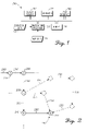
- FIG. 1 is a schematic representation of an embodiment of a vehicle navigation system
- FIG. 2 is a diagram of a proposed driving route and alternate route segments
- FIG. 3 is a flow chart that illustrates an embodiment of a multi-route navigation process
- FIG. 4 is a flow chart that illustrates an embodiment of a multi-route presentation process
- FIG. 5 is a schematic representation of an exemplary display generated by a vehicle navigation system.
- drivers When using a vehicle navigation system, drivers will sometimes deviate from a proposed route because they are aware of an alternate path, they do not like the proposed route, they want to take a side trip, or for some other reason.
- Traditionally when a driver deviates from a predetermined route calculated by a navigation system, the system will announce that it is recalculating the route in an attempt to direct the driver back to the original route.
- Drivers tend to disable voice prompts of a vehicle navigation system to avoid being annoyed by recalculation prompts and related guidance instructions.
- An embodiment of an electronic navigation system as described here can reduce or eliminate the bothersome experience associated with the recalculation of a proposed route, while still providing valuable driving instructions that lead to the desired destination.
- the system allows the driver to feel more in control by giving the driver alternatives at route nodes when appropriate, and by indicating to the driver when a given route segment really should be followed.
- Certain embodiments of the navigation system will calculate alternate routes corresponding to each node or driver decision point along an originally planned route. Thus, when the driver misses a planned maneuver or chooses to take an alternate path, the system can automatically and quickly switch to the appropriate pre-calculated alternate route without delay.
- This methodology provides useful alternate route information to the driver in a seamless manner and without forcing the driver back to the originally planned route.
- the system may also show the primary route and one or more alternative routes, along with acceptable paths of travel at each driver decision point, to give options to the driver rather than providing only one proposed route.
- the navigation system need not calculate all possible routes from a given driver decision point. Rather, the system could selectively calculate and store alternate routes that are realistic and practical. For example, the system might selectively process alternate routes that do not add a significant or unreasonable amount of driving time or mileage to the originally planned route. As another example, the system need not compute alternate routes that would generally lead the vehicle away from the intended destination.
- the vehicle navigation system could also calculate and process alternate routes in advance to determine the relative importance or criticality of approaching maneuvers.
- the system can indicate to the driver whether or not certain maneuvers are optional, highly recommended, mandatory, etc.
- one or more secondary routes are computed and analyzed to determine what might happen if the driver misses the recommended route instruction. If a secondary route will significantly or noticeably impact the desired route (e.g., it adds fifteen miles to the commute), then the system will notify the driver of the relative importance of the approaching maneuver. Such additional guidance will help the driver decide whether to focus on or casually follow a given driving instruction.
- the indication of relative importance can be conveyed to the driver in a variety of ways, including, without limitation: color coding; voice prompt authoritativeness; voice prompt timing; a time difference; a mileage difference; or the like. For example, if the vehicle is traveling on a highway and is supposed to exit before a bridge, then the system could inform the driver well in advance that the highway must be exited before the bridge, otherwise at least twenty minutes will be added to the drive time.
- FIG. 1 is a schematic representation of an embodiment of a navigation system 100 , which is suitably configured to instruct an operator.
- the system 100 is deployed onboard a host vehicle, such as an automobile.
- the system 100 may be implemented as part of an onboard vehicle navigation system, an onboard vehicle entertainment system, an onboard display system, an onboard vehicle instrumentation cluster, or the like.
- the system 100 may be implemented as a portable system or incorporated into a mobile device such as a mobile telephone, a personal digital assistant, a video game device, or the like.
- the illustrated embodiment of the system 100 includes, without limitation: a display element 102 ; at least one speaker 104 ; a user interface 106 ; a navigation processor 108 ; and a suitable amount of memory 110 .
- the various components of the system 100 are coupled together in a manner that facilitates the communication of data, instructions, control signals, and possibly other signals.
- the system 100 may include additional components configured to perform conventional functions that are unrelated to the subject matter described here.
- the navigation processor 108 is configured to perform or otherwise support the various operations and functions described herein.
- the navigation processor 108 may include one processor device or a plurality of cooperating processor devices.
- the navigation processor 108 may be implemented or performed with a general purpose processor, a content addressable memory, a digital signal processor, an application specific integrated circuit, a field programmable gate array, any suitable programmable logic device, discrete gate or transistor logic, discrete hardware components, or any combination designed to perform the functions described here.
- a processor device may be realized as a microprocessor, a controller, a microcontroller, or a state machine.
- a processor device may be implemented as a combination of computing devices, e.g., a combination of a digital signal processor and a microprocessor, a plurality of microprocessors, one or more microprocessors in conjunction with a digital signal processor core, or any other such configuration.
- the memory 110 accommodates the saving and storing of data, software program code, and other information used to support the operation of the system 100 .
- the memory 110 may be realized as RAM memory, flash memory, EPROM memory, EEPROM memory, registers, a hard disk, a removable disk, a CD-ROM, or any other form of storage medium known in the art.
- the memory 110 can be coupled to other elements of the system 100 to support the reading of information from, and the writing of information to, the memory 110 .
- the memory 110 is integral to the navigation processor 108 .
- the navigation processor 108 and the memory 110 may reside in an ASIC or be implemented with a system on a chip.
- the navigation processor 108 obtains location data 112 from an appropriate source that provides data indicative of the current vehicle location or position.
- the location data source is realized as an onboard GPS receiver/processor that derives the current geographic position of the vehicle from GPS data received by the vehicle in real-time or substantially real-time.
- the navigation processor 108 is also configured to obtain map data 114 from an appropriate source that provides data indicative of current cartographic, topological, location, road, and possibly other data useful to the system 100 .
- the map data 114 can represent locally stored, cached, downloaded, or accessible information, which can be processed by the navigation processor 108 .
- the map data source(s) may be realized as one or more hard disks, semiconductor memory devices, portable storage media, or the like.
- the map data source(s) may be realized as an onboard memory cache that temporarily stores the map data 114 that is downloaded from remote databases.
- the display element 102 , the speaker(s) 104 , and the user interface 106 may be configured in accordance with conventional vehicle navigation, information, or instrumentation systems to enable onboard interaction with the vehicle operator.
- the display element 102 may be a suitably configured LCD, plasma, CRT, OLED, or head-up display, which may or may not be utilized for other vehicle functions.
- an appropriate display driver of the system 100 can provide rendering control signals to the display element 102 to cause the display element 102 to render maps, proposed routes, roads, navigation direction arrows, and other graphical representations, elements, or indicia as necessary to support the function of the system 100 .
- the speaker(s) 104 may be devoted to the system 100 , may be realized as part of the audio system of the vehicle, or may be realized as part of another system or subsystem of the vehicle. Briefly, speaker(s) 104 may receive audio signals from the navigation processor 108 , where such audio signals convey navigation instructions, user prompts, warning signals, and other audible signals as necessary to support the function of the system 100 .
- User interface 106 is configured to allow the vehicle operator to enter data and/or control the functions and features of the system 100 .
- the operator can manipulate the user interface 106 to enter a starting location and a destination location for the vehicle, where the starting and destination locations are utilized by the system 100 for purposes of route planning. If the desired starting location corresponds to the current vehicle location, then the operator need not enter the starting location if the system 100 includes a source of current vehicle position information.
- the user interface 106 may be realized using any conventional device or structure, including, without limitation: a keyboard or keypad; a touch screen (which may be incorporated into the display element 102 ); a voice recognition system; a cursor control device; a joystick or knob; or the like.
- the system 100 can perform a number of navigation functions, operations, processes, and methods, which are described in more detail herein. Typically, the system 100 generates and presents guidance information and instructions associated with a proposed or default route to a destination. In addition, the system 100 generates at least one alternate or secondary route in advance such that the alternate route can be activated with little to no delay when needed.
- FIG. 2 is a diagram of a proposed driving route 200 and alternate route segments that lead to a destination location 202 .
- the proposed driving route 200 includes five segments, which are separated by nodes or driver decision points.
- the circles represent the different driver decision points.
- a “driver decision point” is any location, position, intersection, landmark, waypoint, street name, measure of distance, on-ramp/off-ramp, or the like, that might be used by the navigation system as a reference for providing route guidance.
- a driver decision point may be associated with one of more of the following instructions, without limitation: turn left or right; veer left or right; stay left or right; proceed straight; make a U-turn; exit or enter a road, highway, or freeway; stop; arrive at destination; or the like.
- the proposed driving route 200 is defined by five driver decision points (the numbered circles in FIG. 2 ). For this example, prior to the first driver decision point 204 the navigation system might announce (audibly and/or visually) an instruction to continue ahead or proceed straight on the current path. Alternatively, since no driving maneuver is required at the first driver decision point 204 , the navigation system could remain silent at this point.
- the second driver decision point 206 corresponds to an instruction to turn right
- the third driver decision point 208 is associated with an instruction to continue straight (or, in some embodiments, no instruction)
- the fourth driver decision point 210 corresponds to an instruction to turn left
- the fifth driver decision point 212 represents the destination location 202 .
- FIG. 2 also depicts two alternate routes that could be taken from the third driver decision point 208 . Either of these two alternate routes could result if the vehicle diverts from the original proposed driving route 200 . For this example, if the vehicle turns left at the third driver decision point 208 , then a first alternate route 220 may be taken. If, however, the vehicle makes a sharp left turn at the third driver decision point 208 , then a second alternate route 230 may be taken. As depicted in FIG. 2 , the first alternate route 220 results in some additional time and mileage relative to the proposed driving route 200 . On the other hand, the second alternate route 230 would result in a significant amount of additional time and mileage. Thus, the first alternate route 220 is preferred over the second alternate route 230 . As explained in more detail herein, certain embodiments of a navigation system might provide information prior to the third driver decision point 208 , such that the driver can decide how best to maneuver the vehicle at that point.
- FIG. 3 is a flow chart that illustrates an embodiment of a multi-route navigation process 300 .
- the process 300 may be performed by, for example, the navigation system 100 .
- the various tasks performed in connection with the process 300 may be performed by software, hardware, firmware, or any combination thereof.
- the following description of the process 300 may refer to elements mentioned above in connection with FIG. 1 .
- portions of the process 300 may be performed by different elements of the described system, e.g., the navigation processor, the memory element, the display element, or the like.
- the process 300 may include any number of additional or alternative tasks, the tasks shown in FIG. 3 need not be performed in the illustrated order, and the process 300 may be incorporated into a more comprehensive procedure or process having additional functionality not described in detail herein.
- one or more of the illustrated tasks may be omitted.
- the multi-route navigation process 300 represents one exemplary technique for pre-calculating and storing one or more alternate routes to a destination location.
- the process 300 may begin by obtaining a starting location and a destination location for the vehicle (task 302 ).
- the starting and destination locations may be utilized to determine one or more potential routes or potential route sections to be recommended for travel to the destination location.
- the process 300 generates a proposed route to the destination location (task 304 ).
- the proposed route generated during the task 304 can be defined by one or more driver decision points, along with their associated driving maneuvers. This proposed route can be saved for use as the default route.
- the process 300 may generate more than one proposed route for selection by the vehicle operator.
- the process 300 will provide navigation instructions corresponding to the currently active route to the vehicle operator in an ongoing manner, as is understood by those familiar with vehicle/portable navigation systems.
- the navigation instructions may be realized as graphical reminders, audible warnings or instructions, a printed map indicating the proposed route, or the like.
- a navigation system that executes the multi-route navigation process 300 pre-calculates at least one alternate route to the destination location (task 306 ). This pre-calculation occurs some time before the vehicle reaches an approaching driver decision point, e.g., the next driver decision point.
- the alternate route provides driving instructions and guidance between the approaching driver decision point and the destination location, and the alternate route is different than the corresponding portion of the proposed route.
- an alternate route for the next approaching driver decision point is pre-calculated when the vehicle is near, has passed, or has satisfied the driving maneuver for, the last driver decision point.
- an alternate route for an approaching driver decision point can be pre-calculated at any time before the vehicle reaches that point, for example, two or more driver decision points ahead of time.
- Pre-calculation of alternate routes considers one or more of the possible ways that the vehicle might divert from the currently active route at the approaching driver decision point. For instance, if the default route instructs the driver to veer left at a fork in the road, then the task 306 will pre-calculate one or more alternate routes that assume the vehicle instead veers right. As another example, if the default route instructs the driver to proceed straight at a four-way intersection, then the task 306 will pre-calculate at least one alternate route that assumes the vehicle turns right, at least one alternate route that assumes the vehicle turns left, and possibly at least one alternate route that assumes the vehicle makes a U-turn. In practice, the task 306 need not completely re-calculate the route to the destination location. Rather, the task 306 could merely re-calculate a path that brings the vehicle back to a driver decision point that is included in the original proposed route.
- the multi-route navigation process 300 can save the alternate route(s) for subsequent activation (task 308 ).
- alternate routes can be stored for quick and virtually immediate activation if necessary.
- Such pre-calculation and saving of alternate routes enhances the user experience of the navigation system, and reduces or eliminates delay that is normally associated with on-the-fly dynamic route recalculation.
- the multi-route navigation process 300 need not pre-calculate each and every possible alternate route to the destination location.
- the process 300 could implement a filtering or selection scheme that limits pre-calculation of alternate routes to a manageable, reasonable, and realistic number, and/or that limits pre-calculation of alternate routes to those that result in less impact on the commute.
- the process 300 could compare a plurality of potential routes to the proposed route, and select or prioritize the potential routes in a manner that is influenced by the comparison.
- selectivity or priority may be influenced by any appropriate metric that indicates a difference between the originally planned route and an alternate route.
- a difference metric could be a metric such as, without limitation: a distance metric; a travel time metric; a traffic congestion metric; a fuel consumption metric; an energy consumption metric; a vehicle emissions metric; a road condition metric; a sightseeing metric; an undesirable area metric; a services (restaurants, hotels, gas, etc.) metric; a preferred route metric; a metric related to past user behavior at the driver decision point; or any combination thereof.
- a potential route might be selected for consideration if its respective difference metric satisfies a threshold criteria.
- the process may favor alternate routes that add less than a threshold amount of time to the originally planned route and/or alternate routes that add less than a threshold distance to the originally planned route.
- the process may disregard alternate routes that might lead the vehicle onto single lane roads.
- the multi-route navigation process 300 pre-calculates and saves one or more alternate routes, an alternate route need not be activated or executed until needed.
- the navigation system can save and update alternate routes until it detects that the vehicle has diverted from its currently designated route. This allows the system to quickly switch to a different route without having to compute the new route on the fly.
- the exemplary embodiment described here pre-calculates and updates its alternate routes when the vehicle is near a driver decision point.
- the navigation system pre-calculates one or more alternate routes for the next approaching driver decision point after the vehicle passes the immediately preceding driver decision point.
- the navigation system pre-calculates at least one alternate route for the next driver decision point.
- the illustrated embodiment of the process 300 detects when the vehicle is near, at, or past a driver decision point (query task 310 ). If so, then the process 300 will also check whether the vehicle has diverted from the proposed route at that driver decision point (query task 312 ). In practice, query task 312 checks whether the vehicle has performed the predetermined and designated driving maneuver associated with the current driver decision point.
- the process 300 detects that the vehicle has diverted from the proposed route, then the navigation system activates a saved alternate route (task 314 ). Thereafter, the navigation system continues with the currently activated route (task 316 ). Moreover, since query task 310 has detected that the vehicle is near, at, or past a driver decision point, the process 300 precalculates at least one updated alternate route (task 318 ). This updating will be associated with the next approaching driver decision point, resulting in one or more potential alternate routes that might be taken by the vehicle at that next point. After pre-calculating the updated alternate route(s), the process 300 may return to task 308 to save those route(s).
- query task 312 determines that the currently activated route was followed, then the process 300 leads to task 312 and continues as described above. Thus, the current route remains active, and the process 300 proceeds to pre-calculate the next possible alternate routes.
- the multi-route navigation process 300 may continue in this manner until the vehicle reaches the destination location, and any number of alternate routes may be pre-calculated in a dynamic manner as the vehicle drives to the destination location.
- FIG. 4 is a flow chart that illustrates an embodiment of a multi-route presentation process 400 .
- the process 400 may be performed by, for example, the navigation system 100 .
- the various tasks performed in connection with the process 400 may be performed by software, hardware, firmware, or any combination thereof.
- the following description of the process 400 may refer to elements mentioned above in connection with FIG. 1 and FIG. 3 .
- portions of the process 400 may be performed by different elements of the described system, e.g., the navigation processor, the memory element, the display element, or the like.
- process 400 may include any number of additional or alternative tasks, the tasks shown in FIG. 4 need not be performed in the illustrated order, and the process 400 may be incorporated into a more comprehensive procedure or process having additional functionality not described in detail herein.
- the process 400 may be combined with the process 300 , or the two processes may be executed in parallel.
- one or more of the illustrated tasks may be omitted.
- the multi-route presentation process 400 assumes that one or more alternate routes (corresponding to the next approaching driver decision point) have been pre-calculated and saved, as explained above. For simplicity and ease of description, this embodiment of the process 400 assumes that one alternate route has been pre-calculated and saved. Accordingly, the process 400 begins by comparing the proposed route to the alternate route (task 402 ). The resulting route comparison can be used to determine one or more applicable difference metric values (task 404 ) that indicate some practical difference between the two routes.
- the difference metric used here may be related to or otherwise associated with any of the following, without limitation: driving distance; travel time; traffic congestion; fuel consumption or economy; energy consumption or economy; vehicle emissions; road condition; sightseeing content; the preference or status of the area; available services (restaurants, hotels, gas, etc.); the preference or status of the route; past user behavior at the driver decision point; or any combination thereof.
- the process 400 displays at least one segment or section of the proposed route in one way, and displays at least one segment or section of the alternate route in a different way, to visually distinguish the proposed route from the alternate route.
- the proposed route may be rendered using first visually distinguishable characteristics and the alternate route may be rendered using second visually distinguishable characteristics (task 406 ).
- the different visually distinguishable characteristics may correspond to any of the following characteristics, individually or in any combination thereof: different colors; different brightness; different transparency levels; different translucency levels; different line patterns; different line thickness; different shapes; different sizes; different flicker patterns; different focus levels; different sharpness levels; different clarity levels; different texturing; different shadowing; varying animations that might depict the relative time/speed of the alternate route; or the like.
- FIG. 5 is a schematic representation of an exemplary display 500 generated by a vehicle navigation system.
- the display 500 is a simplified depiction of a segment of a proposed route 502 , along with a segment of a first alternate route 504 and a segment of a second alternate route 506 .
- the proposed route 502 calls for the vehicle to continue straight through an intersection 508 .
- the first alternate route 504 assumes that the vehicle turns left at the intersection 508
- the second alternate route 506 assumes that the vehicle turns right at the intersection 508 .
- FIG. 5 schematically depicts three different visually distinguishable characteristics for the proposed route 502 (e.g., a first color, such as green or white), the first alternate route 504 (e.g., a second color represented by the cross hatching, such as red), and the second alternate route 506 (e.g., a third color represented by the stippling, such as amber).
- the first alternate route 504 may be displayed in red as an indication that it is not a preferred or desirable route.
- the second alternate route 506 may be displayed in amber as an indication that it is an appropriate or acceptable route.
- the multi-route presentation process 400 may also present (display or announce) to the operator of the vehicle some indicia of the difference metric associated with the alternate route under consideration (task 408 ).
- different visually distinguishable characteristics as described above
- visible indicia text, labels, icons, or the like
- FIG. 5 depicts one possible implementation that employs text boxes that contain one or more difference metric values for the alternate routes.
- the first alternate route 504 is displayed with a text box 510 that includes an indication of the estimated additional driving distance (forty miles) and the estimated additional driving time (two hours) that will be experienced if the vehicle is diverted to the first alternate route 504 along the way to the destination location.
- the second alternate route 506 is displayed with a text box 512 that includes an indication of the estimated additional driving distance (five miles) and the estimated additional driving time (fifteen minutes) that will be experienced if the vehicle is diverted to the second alternate route 506 along the way to the destination location.
- the calculated difference metric is analyzed and compared to a threshold value (query task 410 ).
- the threshold value might correspond to a tolerable or acceptable amount of inconvenience, additional time, additional distance, etc., and the threshold value could be selected or configured by the user.
- This threshold value is used by the navigation system to determine the relative importance, criticality, desirability, or priority of the upcoming driving maneuver that is associated with the approaching driver decision point.
- the threshold value may be defined to be a predetermined distance (such as ten miles), a predetermined amount of time (such as thirty minutes), a predetermined measure of fuel consumption (such as a gallon of gasoline), or the like.
- the threshold value may contemplate any appropriate criteria, including a combination of different criteria.
- the threshold value may contemplate travel time, distance, and/or fuel efficiency.
- the embodiment depicted in FIG. 5 assumes that a lower difference metric value is preferred over a higher difference metric value. In other embodiments, of course, the opposite may hold (depending upon the particular metric used).
- the multi-route presentation process 400 presents indicia of an approaching “low importance” or “optional” or “low priority” driving maneuver (task 412 ).
- the process 400 presents indicia of an approaching “high importance” or “mandatory” or “high priority” driving maneuver (task 414 ).
- the content of the indicia (whether displayed and/or announced) will be responsive to, or otherwise influenced by, the calculated difference metric value.
- this example relates to an embodiment having two different priority or importance levels, the number of priorities or levels need not be limited to only two. In this regard, a navigation system and the process 400 could be suitably configured to support three (low/intermediate/high) or more priorities.
- the navigation system can indicate the importance or criticality of a recommended driving maneuver in any number of ways.
- the system may render route segments using visually distinguishable characteristics that are coded to indicate the importance of a driving maneuver (see FIG. 5 ).
- that alternate route segment may be colored red to indicate that it should be avoided.
- the difference metric value or values themselves may be presented (see FIG. 5 ) so that the driver can appreciate the actual impact an alternate route might have on the commute.
- graphical icons or symbols could be used to indicate the importance of a given driving maneuver.
- the proposed route 502 is identified using a simple arrow 520 .
- the first alternate route 504 is identified using a visibly distinguishable arrow 522 that indicates an undesirable route.
- the second alternate route 506 is identified using yet another type of arrow 524 that indicate an acceptable route.
- the importance, criticality, or nature of an approaching driving maneuver could also be indicated with a different annunciation or display scheme. For example, if the next driver decision point (and its corresponding driving maneuver) has little or no acceptable alternate routes associated therewith, then the process 400 could provide an appropriate warning well in advance, display or announce that the next driving maneuver should be treated as mandatory, and/or present the associated driving instruction in an assertive or authoritative tone. In contrast, if all of the possible alternate routes associated with the next driver decision point are acceptable (e.g., none of them would add significant time or distance to the commute), then the process 400 need not take any special action, it may display or announce that the next driving maneuver can be treated as optional, and/or present the associated driving instruction in a less assertive or less authoritative tone.
- the frequency of announcements and/or the amount of lead time given before the upcoming driver decision point may be influenced by the relative importance of the next driving maneuver.
- the driver may be reminded more often and with plenty of lead time.
- the assertiveness of the navigation system could vary depending upon the relative importance of the maneuver.
- important maneuvers could preempt certain system applications/tasks to inform the user of the approaching maneuver, while relatively unimportant maneuvers might have no preemptive impact.
- the navigation system could employ different animated turn indications and/or driving instructions, or employ different voice prompt volume levels in a modulated manner that is influenced by the relative importance of the approaching maneuver.
Abstract
Description
Claims (20)
Priority Applications (2)
| Application Number | Priority Date | Filing Date | Title |
|---|---|---|---|
| US12/487,852 US8942918B2 (en) | 2009-06-19 | 2009-06-19 | Multiple route pre-calculation and presentation for a vehicle navigation system |
| DE102010023942.9A DE102010023942B4 (en) | 2009-06-19 | 2010-06-16 | Navigation system and method for instructing an operator of a vehicle |
Applications Claiming Priority (1)
| Application Number | Priority Date | Filing Date | Title |
|---|---|---|---|
| US12/487,852 US8942918B2 (en) | 2009-06-19 | 2009-06-19 | Multiple route pre-calculation and presentation for a vehicle navigation system |
Publications (2)
| Publication Number | Publication Date |
|---|---|
| US20100324817A1 US20100324817A1 (en) | 2010-12-23 |
| US8942918B2 true US8942918B2 (en) | 2015-01-27 |
Family
ID=43355025
Family Applications (1)
| Application Number | Title | Priority Date | Filing Date |
|---|---|---|---|
| US12/487,852 Active 2033-01-10 US8942918B2 (en) | 2009-06-19 | 2009-06-19 | Multiple route pre-calculation and presentation for a vehicle navigation system |
Country Status (2)
| Country | Link |
|---|---|
| US (1) | US8942918B2 (en) |
| DE (1) | DE102010023942B4 (en) |
Cited By (3)
| Publication number | Priority date | Publication date | Assignee | Title |
|---|---|---|---|---|
| US10769953B1 (en) | 2019-06-11 | 2020-09-08 | Toyota Motor North America, Inc. | Vehicle-to-vehicle sensor data sharing |
| US11099016B2 (en) | 2019-03-29 | 2021-08-24 | Naver Corporation | System and method for generating pedestrian tours |
| US11315427B2 (en) | 2019-06-11 | 2022-04-26 | Toyota Motor North America, Inc. | Vehicle-to-vehicle sensor data sharing |
Families Citing this family (42)
| Publication number | Priority date | Publication date | Assignee | Title |
|---|---|---|---|---|
| EP2382444A1 (en) * | 2008-12-22 | 2011-11-02 | Tele Atlas North America, Inc. | Methods, devices and map databases for green routing |
| GB2475486B (en) * | 2009-11-18 | 2012-01-25 | Vodafone Plc | Method for identifying a candidate part of a map to be updated |
| JP4864149B2 (en) * | 2010-02-23 | 2012-02-01 | 本田技研工業株式会社 | Navigation server and navigation system |
| DE102010035373A1 (en) * | 2010-08-25 | 2012-03-01 | Elektrobit Automotive Gmbh | Technology for screen-based route manipulation |
| US8704669B2 (en) | 2010-11-08 | 2014-04-22 | Ford Global Technologies, Llc | Vehicle system reaction to medical conditions |
| US9122775B2 (en) | 2011-01-03 | 2015-09-01 | Ford Global Technologies, Llc | Medical data acquisition and provision |
| US9449514B2 (en) * | 2011-05-18 | 2016-09-20 | Ford Global Technologies, Llc | Methods and apparatus for adaptive vehicle response to air quality states |
| KR20140014262A (en) | 2011-06-03 | 2014-02-05 | 애플 인크. | Devices and methods for comparing and selecting alternative navigation routes |
| US8706397B2 (en) * | 2011-07-11 | 2014-04-22 | Harman International Industries, Incorporated | System and method for determining an optimal route using aggregated route information |
| US9361271B2 (en) * | 2011-09-27 | 2016-06-07 | Wipro Limited | Systems and methods to enable eco-driving |
| US20130103300A1 (en) * | 2011-10-25 | 2013-04-25 | Nokia Corporation | Method and apparatus for predicting a travel time and destination before traveling |
| KR101288323B1 (en) | 2011-12-16 | 2013-07-23 | 에스케이플래닛 주식회사 | Multi route providing navigation apparatus and method thereof |
| US8855925B2 (en) * | 2012-01-20 | 2014-10-07 | GM Global Technology Operations LLC | Adaptable navigation device |
| EP2626846B1 (en) * | 2012-02-08 | 2014-05-14 | Skobbler GmbH | System and method for warning a driver of a vehicle about traffic situations |
| US10156455B2 (en) | 2012-06-05 | 2018-12-18 | Apple Inc. | Context-aware voice guidance |
| US9997069B2 (en) | 2012-06-05 | 2018-06-12 | Apple Inc. | Context-aware voice guidance |
| US9886794B2 (en) | 2012-06-05 | 2018-02-06 | Apple Inc. | Problem reporting in maps |
| US8983778B2 (en) | 2012-06-05 | 2015-03-17 | Apple Inc. | Generation of intersection information by a mapping service |
| US10176633B2 (en) | 2012-06-05 | 2019-01-08 | Apple Inc. | Integrated mapping and navigation application |
| US9418672B2 (en) | 2012-06-05 | 2016-08-16 | Apple Inc. | Navigation application with adaptive instruction text |
| US8965696B2 (en) | 2012-06-05 | 2015-02-24 | Apple Inc. | Providing navigation instructions while operating navigation application in background |
| US9482296B2 (en) | 2012-06-05 | 2016-11-01 | Apple Inc. | Rendering road signs during navigation |
| US11935190B2 (en) | 2012-06-10 | 2024-03-19 | Apple Inc. | Representing traffic along a route |
| US9171464B2 (en) | 2012-06-10 | 2015-10-27 | Apple Inc. | Encoded representation of route data |
| US10817968B2 (en) * | 2013-08-20 | 2020-10-27 | Intelligent Imaging Systems, Inc. | Vehicle traffic and vehicle related transaction control system |
| US9970775B2 (en) * | 2013-11-21 | 2018-05-15 | Red Hat Israel, Ltd. | Determining alternative route by navigation system |
| US10113879B2 (en) | 2014-03-03 | 2018-10-30 | Apple Inc. | Hierarchy of tools for navigation |
| US9513132B2 (en) * | 2014-08-21 | 2016-12-06 | Here Global B.V. | Measuring quality in optimal navigation routes by navigation systems |
| CN107003141B (en) * | 2014-10-20 | 2020-07-07 | 通腾导航技术股份有限公司 | Alternative routes |
| US9222795B1 (en) * | 2014-10-22 | 2015-12-29 | Volkswagen Ag | Apparatus, system and method for detour guidance in a navigation system |
| JP2016090273A (en) * | 2014-10-30 | 2016-05-23 | パイオニア株式会社 | Information processing system, information processing method, and information processing program |
| DE102016220945A1 (en) * | 2015-11-06 | 2017-05-11 | Ford Global Technologies, Llc | Method and device for supporting a maneuvering process of a motor vehicle |
| DE102017207243A1 (en) * | 2017-04-28 | 2018-10-31 | Continental Automotive Gmbh | Method and device for generating dynamic indications about a change of a route guidance |
| US10495471B2 (en) * | 2017-05-09 | 2019-12-03 | Uber Technologies, Inc. | Destination changes in autonomous vehicles |
| JP6939234B2 (en) * | 2017-08-14 | 2021-09-22 | 株式会社Jvcケンウッド | Guidance device, guidance method, and guidance program |
| US10591309B2 (en) * | 2017-10-12 | 2020-03-17 | International Business Machines Corporation | Autonomous vehicle-based guided tour rule selection |
| US10711488B2 (en) * | 2018-06-05 | 2020-07-14 | Isac Tabib | Electric door lock controller and monitoring system and method of use |
| US11462101B2 (en) | 2019-11-18 | 2022-10-04 | International Business Machines Corporation | Non-essential autonomous vehicle rerouting |
| IT202000023227A1 (en) * | 2020-10-01 | 2022-04-01 | Laura Quinale | METHOD AND DEVICE FOR DETERMINING A ROUTE |
| DE102022112169A1 (en) | 2022-05-16 | 2023-11-16 | Bayerische Motoren Werke Aktiengesellschaft | Method for providing a set of decision points during a trip with a vehicle from a backend server to the vehicle, computer-readable medium, system and vehicle |
| DE102022112167A1 (en) | 2022-05-16 | 2023-11-16 | Bayerische Motoren Werke Aktiengesellschaft | Method for querying predicted routes from a backend server by a vehicle, computer-readable medium, system, and vehicle |
| DE102022112170A1 (en) | 2022-05-16 | 2023-11-16 | Bayerische Motoren Werke Aktiengesellschaft | Method for providing navigation data while driving a vehicle from a backend server to the vehicle, computer-readable medium, system and vehicle |
Citations (18)
| Publication number | Priority date | Publication date | Assignee | Title |
|---|---|---|---|---|
| US5220507A (en) * | 1990-11-08 | 1993-06-15 | Motorola, Inc. | Land vehicle multiple navigation route apparatus |
| US5508930A (en) * | 1991-12-23 | 1996-04-16 | Motorola, Inc. | Vehicle navigation apparatus with new route replanning apparatus |
| US5659476A (en) * | 1994-12-22 | 1997-08-19 | Motorola Inc. | Land vehicle navigation apparatus and method for planning a recovery route |
| EP0803852A1 (en) | 1996-04-23 | 1997-10-29 | Mannesmann VDO AG | Method and device to guide a vehicle |
| US5699056A (en) * | 1994-12-28 | 1997-12-16 | Omron Corporation | Traffic information system |
| US5742922A (en) * | 1996-02-12 | 1998-04-21 | Hyundai Motor Company | Vehicle navigation system and method for selecting a route according to fuel consumption |
| DE19748077A1 (en) | 1996-11-01 | 1998-05-20 | Alpine Electronics Inc | Automobile route navigation system |
| US5774827A (en) * | 1996-04-03 | 1998-06-30 | Motorola Inc. | Commuter route selection system |
| US6163751A (en) * | 1996-10-26 | 2000-12-19 | Mannesmann Vdo Ag | Navigation system for a vehicle |
| US6256577B1 (en) * | 1999-09-17 | 2001-07-03 | Intel Corporation | Using predictive traffic modeling |
| US20020052689A1 (en) * | 2000-10-31 | 2002-05-02 | Atsushi Yamashita | Navigation apparatus |
| EP1271104A2 (en) | 2001-06-29 | 2003-01-02 | Robert Bosch Gmbh | Vehicle navigation method |
| US6546337B2 (en) * | 2001-08-22 | 2003-04-08 | Matsushita Electric Industrial Co., Ltd. | Method of integrating subscriber based traffic navigation and hospitality data with a global positioning system |
| US6701250B1 (en) * | 1998-12-21 | 2004-03-02 | Robert Bosch Gmbh | Method of directing a driver of a vehicle from at least one starting point to at least one destination |
| WO2005005928A1 (en) | 2003-07-10 | 2005-01-20 | Robert Bosch Gmbh | Method for route navigation in motor vehicles and corresponding navigation device |
| EP1722196A1 (en) | 2005-05-09 | 2006-11-15 | Siemens Aktiengesellschaft | Method for calculating a route in a navigation system |
| DE102006057427A1 (en) | 2006-12-06 | 2008-06-12 | Robert Bosch Gmbh | Route guidance method and arrangement for carrying out such and a corresponding computer program and a corresponding processor-readable storage medium |
| DE102007017174A1 (en) | 2007-04-12 | 2008-10-16 | Bayerische Motoren Werke Aktiengesellschaft | Car navigation system |
Family Cites Families (1)
| Publication number | Priority date | Publication date | Assignee | Title |
|---|---|---|---|---|
| US5291412A (en) * | 1992-03-24 | 1994-03-01 | Zexel Corporation | Navigation system |
-
2009
- 2009-06-19 US US12/487,852 patent/US8942918B2/en active Active
-
2010
- 2010-06-16 DE DE102010023942.9A patent/DE102010023942B4/en active Active
Patent Citations (24)
| Publication number | Priority date | Publication date | Assignee | Title |
|---|---|---|---|---|
| US5220507A (en) * | 1990-11-08 | 1993-06-15 | Motorola, Inc. | Land vehicle multiple navigation route apparatus |
| US5508930A (en) * | 1991-12-23 | 1996-04-16 | Motorola, Inc. | Vehicle navigation apparatus with new route replanning apparatus |
| US5659476A (en) * | 1994-12-22 | 1997-08-19 | Motorola Inc. | Land vehicle navigation apparatus and method for planning a recovery route |
| US5699056A (en) * | 1994-12-28 | 1997-12-16 | Omron Corporation | Traffic information system |
| US5742922A (en) * | 1996-02-12 | 1998-04-21 | Hyundai Motor Company | Vehicle navigation system and method for selecting a route according to fuel consumption |
| US5774827A (en) * | 1996-04-03 | 1998-06-30 | Motorola Inc. | Commuter route selection system |
| EP0803852A1 (en) | 1996-04-23 | 1997-10-29 | Mannesmann VDO AG | Method and device to guide a vehicle |
| DE19616071A1 (en) | 1996-04-23 | 1997-10-30 | Vdo Schindling | Method and device for guiding a vehicle |
| US6163751A (en) * | 1996-10-26 | 2000-12-19 | Mannesmann Vdo Ag | Navigation system for a vehicle |
| DE19748077A1 (en) | 1996-11-01 | 1998-05-20 | Alpine Electronics Inc | Automobile route navigation system |
| US6701250B1 (en) * | 1998-12-21 | 2004-03-02 | Robert Bosch Gmbh | Method of directing a driver of a vehicle from at least one starting point to at least one destination |
| US6256577B1 (en) * | 1999-09-17 | 2001-07-03 | Intel Corporation | Using predictive traffic modeling |
| US20020052689A1 (en) * | 2000-10-31 | 2002-05-02 | Atsushi Yamashita | Navigation apparatus |
| EP1271104A2 (en) | 2001-06-29 | 2003-01-02 | Robert Bosch Gmbh | Vehicle navigation method |
| DE10131432A1 (en) | 2001-06-29 | 2003-01-09 | Bosch Gmbh Robert | Method for navigating a vehicle |
| US6546337B2 (en) * | 2001-08-22 | 2003-04-08 | Matsushita Electric Industrial Co., Ltd. | Method of integrating subscriber based traffic navigation and hospitality data with a global positioning system |
| WO2005005928A1 (en) | 2003-07-10 | 2005-01-20 | Robert Bosch Gmbh | Method for route navigation in motor vehicles and corresponding navigation device |
| DE10331155A1 (en) | 2003-07-10 | 2005-01-27 | Robert Bosch Gmbh | Method for route navigation in motor vehicles and navigation device for this purpose |
| EP1722196A1 (en) | 2005-05-09 | 2006-11-15 | Siemens Aktiengesellschaft | Method for calculating a route in a navigation system |
| DE102005021271B3 (en) | 2005-05-09 | 2006-12-07 | Siemens Ag | Method for calculating a route in a navigation system |
| DE102006057427A1 (en) | 2006-12-06 | 2008-06-12 | Robert Bosch Gmbh | Route guidance method and arrangement for carrying out such and a corresponding computer program and a corresponding processor-readable storage medium |
| US20100138146A1 (en) | 2006-12-06 | 2010-06-03 | Wilhelm Vogt | Routing method, routing arrangement, corresponding computer program, and processor-readable storage medium |
| DE102007017174A1 (en) | 2007-04-12 | 2008-10-16 | Bayerische Motoren Werke Aktiengesellschaft | Car navigation system |
| US20100094540A1 (en) | 2007-04-12 | 2010-04-15 | Bayerische Motoren Werke Aktiengesellschaft | Motor Vehicle Navigation System |
Non-Patent Citations (1)
| Title |
|---|
| German Office Action, dated Aug. 31, 2011, for German Patent Application No. 10 2010 023 942.9. |
Cited By (5)
| Publication number | Priority date | Publication date | Assignee | Title |
|---|---|---|---|---|
| US11099016B2 (en) | 2019-03-29 | 2021-08-24 | Naver Corporation | System and method for generating pedestrian tours |
| US10769953B1 (en) | 2019-06-11 | 2020-09-08 | Toyota Motor North America, Inc. | Vehicle-to-vehicle sensor data sharing |
| US11315427B2 (en) | 2019-06-11 | 2022-04-26 | Toyota Motor North America, Inc. | Vehicle-to-vehicle sensor data sharing |
| US11710406B2 (en) | 2019-06-11 | 2023-07-25 | Toyota Motor North America, Inc. | Vehicle-to-vehicle sensor data sharing |
| US11961401B2 (en) | 2019-06-11 | 2024-04-16 | Toyota Motor North America, Inc. | Vehicle-to-vehicle sensor data sharing |
Also Published As
| Publication number | Publication date |
|---|---|
| US20100324817A1 (en) | 2010-12-23 |
| DE102010023942A1 (en) | 2011-02-24 |
| DE102010023942B4 (en) | 2018-01-25 |
Similar Documents
| Publication | Publication Date | Title |
|---|---|---|
| US8942918B2 (en) | Multiple route pre-calculation and presentation for a vehicle navigation system | |
| US8260550B2 (en) | Presentation of navigation instructions using variable levels of detail | |
| EP1086358B1 (en) | Navigation system | |
| US8280630B2 (en) | Navigation device | |
| US20100324818A1 (en) | Presentation of navigation instructions using variable content, context and/or formatting | |
| US20050055157A1 (en) | Navigation system having means for determining a route with optimized consumption | |
| WO1992021937A1 (en) | Navigation apparatus and navigation method | |
| JP2007024833A (en) | On-vehicle navigation apparatus | |
| US8340900B2 (en) | Navigation device and alerting method thereof | |
| CN101458093B (en) | Navigation apparatus | |
| JPH08271268A (en) | Demonstration method of navigation apparatus | |
| US20090177388A1 (en) | Method For Operating A Navigation System | |
| JP2000266553A (en) | On-vehicle navigator | |
| JP4926848B2 (en) | Navigation device and route guidance method | |
| JP2010223695A (en) | Navigation system | |
| JP2008241474A (en) | Navigation system and control method therefor | |
| JP2007298338A (en) | Navigation system | |
| JP5845881B2 (en) | Evaluation display system, method and program | |
| JP2004294301A (en) | Method of screen display and program for making computer perform the method | |
| JP2008157894A (en) | Drive support device | |
| JP4295153B2 (en) | Navigation device and driver guidance method | |
| JP2007322305A (en) | Navigation apparatus | |
| JP4329502B2 (en) | Navigation device, navigation program, and storage medium | |
| KR101046411B1 (en) | Vehicle navigation device and its screen display method | |
| JP4987667B2 (en) | Navigation device, method and program |
Legal Events
| Date | Code | Title | Description |
|---|---|---|---|
| AS | Assignment |
Owner name: GM GLOBAL TECHNOLOGY OPERATIONS, INC., MICHIGAN Free format text: ASSIGNMENT OF ASSIGNORS INTEREST;ASSIGNORS:HANSEN, CODY R.;GELLATLY, ANDREW W.;WEISS, JOHN P.;AND OTHERS;REEL/FRAME:022849/0437 Effective date: 20090615 |
|
| AS | Assignment |
Owner name: UNITED STATES DEPARTMENT OF THE TREASURY, DISTRICT Free format text: SECURITY AGREEMENT;ASSIGNOR:GM GLOBAL TECHNOLOGY OPERATIONS, INC.;REEL/FRAME:023201/0118 Effective date: 20090710 |
|
| AS | Assignment |
Owner name: UAW RETIREE MEDICAL BENEFITS TRUST, MICHIGAN Free format text: SECURITY AGREEMENT;ASSIGNOR:GM GLOBAL TECHNOLOGY OPERATIONS, INC.;REEL/FRAME:023162/0048 Effective date: 20090710 |
|
| AS | Assignment |
Owner name: GM GLOBAL TECHNOLOGY OPERATIONS, INC., MICHIGAN Free format text: RELEASE BY SECURED PARTY;ASSIGNOR:UNITED STATES DEPARTMENT OF THE TREASURY;REEL/FRAME:025246/0056 Effective date: 20100420 |
|
| AS | Assignment |
Owner name: GM GLOBAL TECHNOLOGY OPERATIONS, INC., MICHIGAN Free format text: RELEASE BY SECURED PARTY;ASSIGNOR:UAW RETIREE MEDICAL BENEFITS TRUST;REEL/FRAME:025315/0091 Effective date: 20101026 |
|
| AS | Assignment |
Owner name: WILMINGTON TRUST COMPANY, DELAWARE Free format text: SECURITY AGREEMENT;ASSIGNOR:GM GLOBAL TECHNOLOGY OPERATIONS, INC.;REEL/FRAME:025324/0555 Effective date: 20101027 |
|
| AS | Assignment |
Owner name: GM GLOBAL TECHNOLOGY OPERATIONS LLC, MICHIGAN Free format text: CHANGE OF NAME;ASSIGNOR:GM GLOBAL TECHNOLOGY OPERATIONS, INC.;REEL/FRAME:025781/0299 Effective date: 20101202 |
|
| FEPP | Fee payment procedure |
Free format text: PAYOR NUMBER ASSIGNED (ORIGINAL EVENT CODE: ASPN); ENTITY STATUS OF PATENT OWNER: LARGE ENTITY |
|
| AS | Assignment |
Owner name: GM GLOBAL TECHNOLOGY OPERATIONS LLC, MICHIGAN Free format text: RELEASE BY SECURED PARTY;ASSIGNOR:WILMINGTON TRUST COMPANY;REEL/FRAME:034185/0789 Effective date: 20141017 |
|
| STCF | Information on status: patent grant |
Free format text: PATENTED CASE |
|
| MAFP | Maintenance fee payment |
Free format text: PAYMENT OF MAINTENANCE FEE, 4TH YEAR, LARGE ENTITY (ORIGINAL EVENT CODE: M1551) Year of fee payment: 4 |
|
| MAFP | Maintenance fee payment |
Free format text: PAYMENT OF MAINTENANCE FEE, 8TH YEAR, LARGE ENTITY (ORIGINAL EVENT CODE: M1552); ENTITY STATUS OF PATENT OWNER: LARGE ENTITY Year of fee payment: 8 |