US8930833B2 - Method and apparatus to present an integrated process modeler - Google Patents
Method and apparatus to present an integrated process modeler Download PDFInfo
- Publication number
- US8930833B2 US8930833B2 US11/542,281 US54228106A US8930833B2 US 8930833 B2 US8930833 B2 US 8930833B2 US 54228106 A US54228106 A US 54228106A US 8930833 B2 US8930833 B2 US 8930833B2
- Authority
- US
- United States
- Prior art keywords
- instructions
- technical
- executable
- subset
- format
- Prior art date
- Legal status (The legal status is an assumption and is not a legal conclusion. Google has not performed a legal analysis and makes no representation as to the accuracy of the status listed.)
- Active, expires
Links
Images


Classifications
-
- G—PHYSICS
- G06—COMPUTING; CALCULATING OR COUNTING
- G06Q—INFORMATION AND COMMUNICATION TECHNOLOGY [ICT] SPECIALLY ADAPTED FOR ADMINISTRATIVE, COMMERCIAL, FINANCIAL, MANAGERIAL OR SUPERVISORY PURPOSES; SYSTEMS OR METHODS SPECIALLY ADAPTED FOR ADMINISTRATIVE, COMMERCIAL, FINANCIAL, MANAGERIAL OR SUPERVISORY PURPOSES, NOT OTHERWISE PROVIDED FOR
- G06Q10/00—Administration; Management
- G06Q10/06—Resources, workflows, human or project management; Enterprise or organisation planning; Enterprise or organisation modelling
- G06Q10/067—Enterprise or organisation modelling
-
- G—PHYSICS
- G06—COMPUTING; CALCULATING OR COUNTING
- G06Q—INFORMATION AND COMMUNICATION TECHNOLOGY [ICT] SPECIALLY ADAPTED FOR ADMINISTRATIVE, COMMERCIAL, FINANCIAL, MANAGERIAL OR SUPERVISORY PURPOSES; SYSTEMS OR METHODS SPECIALLY ADAPTED FOR ADMINISTRATIVE, COMMERCIAL, FINANCIAL, MANAGERIAL OR SUPERVISORY PURPOSES, NOT OTHERWISE PROVIDED FOR
- G06Q10/00—Administration; Management
-
- G—PHYSICS
- G06—COMPUTING; CALCULATING OR COUNTING
- G06F—ELECTRIC DIGITAL DATA PROCESSING
- G06F3/00—Input arrangements for transferring data to be processed into a form capable of being handled by the computer; Output arrangements for transferring data from processing unit to output unit, e.g. interface arrangements
- G06F3/01—Input arrangements or combined input and output arrangements for interaction between user and computer
- G06F3/048—Interaction techniques based on graphical user interfaces [GUI]
- G06F3/0484—Interaction techniques based on graphical user interfaces [GUI] for the control of specific functions or operations, e.g. selecting or manipulating an object, an image or a displayed text element, setting a parameter value or selecting a range
- G06F3/04842—Selection of displayed objects or displayed text elements
-
- G—PHYSICS
- G06—COMPUTING; CALCULATING OR COUNTING
- G06Q—INFORMATION AND COMMUNICATION TECHNOLOGY [ICT] SPECIALLY ADAPTED FOR ADMINISTRATIVE, COMMERCIAL, FINANCIAL, MANAGERIAL OR SUPERVISORY PURPOSES; SYSTEMS OR METHODS SPECIALLY ADAPTED FOR ADMINISTRATIVE, COMMERCIAL, FINANCIAL, MANAGERIAL OR SUPERVISORY PURPOSES, NOT OTHERWISE PROVIDED FOR
- G06Q10/00—Administration; Management
- G06Q10/10—Office automation; Time management
Landscapes
- Engineering & Computer Science (AREA)
- Business, Economics & Management (AREA)
- Strategic Management (AREA)
- Human Resources & Organizations (AREA)
- Entrepreneurship & Innovation (AREA)
- Theoretical Computer Science (AREA)
- Economics (AREA)
- Physics & Mathematics (AREA)
- General Physics & Mathematics (AREA)
- Operations Research (AREA)
- General Business, Economics & Management (AREA)
- Tourism & Hospitality (AREA)
- Quality & Reliability (AREA)
- Marketing (AREA)
- General Engineering & Computer Science (AREA)
- Game Theory and Decision Science (AREA)
- Educational Administration (AREA)
- Development Economics (AREA)
- Data Mining & Analysis (AREA)
- Human Computer Interaction (AREA)
- Management, Administration, Business Operations System, And Electronic Commerce (AREA)
- Stored Programmes (AREA)
Abstract
A method and apparatus for an integrated process modeler is described. The modeler comprises a non-technical interface to permit design of a business process by a non-technical use and a technical interface to implement substeps of the process to automate technical aspects of the process by a technical user, using the same process modeler. The resulting process designed to be used by non-technical employees, to automatically lead the non-technical employees through the business process.
Description
This application is a continuation of U.S. application Ser. No. 10/334,922, which is now U.S. Pat. No. 7,117,449 B1, entitled “A Method And Apparatus To Present An Integrated Process Modeler,” issued on Oct. 3, 2006, and naming Issac Stephen Levin, Jon Rexford Degenhardt, Atul Suklikar and Peter A. Thorson as inventors. This application is incorporated by reference herein, in its entirety and for all purposes
The present invention relates to modeling, and more particularly to modeling a complex process.
In general, processes followed within an organization's ecosystem are described in various forms in most enterprise environments. This type of modeling is becoming increasingly important, as companies attempt to create uniform processes across the enterprise.
For example, a business analyst may create a process flow for a business process using tools such as Visio and iGrafx. However, in order to automate such processes, a different tool must be used, such as BizTalk, or similar tools.
Transferring such a process is, however, difficult. The business analyst must explain to a developer what each of the steps of the process mean. Then, the developer creates an automated process, which may be used by other employees to actually follow the process sketched out by the business analyst. This process is lengthy and complex, and miscommunication creates rework, thereby delaying implementation.
Additionally, best practices may be provided to corporations. These best practices are automated processes that may be followed for various actions. However, these processes may not match perfectly with the requirements of the customer, and in general are difficult to modify.
A method and apparatus for an integrated process modeler is described. The modeler comprises a non-technical interface to permit design of a business process by a non-technical use and a technical interface to implement substeps of the process to automate technical aspects of the process by a technical user, using the same process modeler. The resulting process designed to be used by non-technical employees, to automatically lead the non-technical employees through the business process.
The present invention is illustrated by way of example, and not by way of limitation, in the figures of the accompanying drawings and in which like reference numerals refer to similar elements and in which:
A method and apparatus for an integrated process modeler is described. The process modeler provides a single tool for designing, debugging and deploying an end-to-end business process. A business process, in this context is a structured series of documented activities organized to achieve a specific business objective. The structure of a particular business process may vary by company, as there are multiple practices for executing any specific objective. Business processes, which can be comprised of multiple sub-processes, are graphically represented in flow diagrams and can span third-party applications. An end-to-end business process is a major business process for the company, one that may span multiple divisions or organizations within as well as outside the company's legal boundaries. An end-to-end business process also can involve interaction with multiple interconnected computer systems executing either autonomously or with end users. The end-to-end business process is typically a long running process occurring over hours, days, weeks or months rather than minutes or seconds. The present system permits the design of such an end-to-end business process, as well as the simpler basic business processes.
By using an end-to-end business process, the modeler spans multiple process types (e.g. enterprise, Siebel, Integration, task), as well as multiple roles (e.g. business analyst, developer), and allows for seamless transition between these components.
The process modeler is capable of designing process flows involving user interaction (e.g. the create call list task). The user interaction design includes the design of a user interface, as well as process steps that require waiting for particular types of inputs from particular users. For one embodiment, both the non-technical and technical user can design these user interaction flows. The process modeler includes the ability to create user interaction as well as integration with other applications.
For one embodiment, user identification logic 110 uses the login and group association of the user to identify the user type. For another embodiment, the user may select his or her preferred interface. For another embodiment, each user that has access to the modeler 100 may be specified to the user identification logic 110. Thus, in addition to selecting the user interface, user identification logic 110 may provide security functions. This prevents unauthorized users from altering any processes, or creating new and incorrect processes.
The business analyst interface 130, as noted above, permits a business analyst or equivalent individual to create a process. This interface 130 may also be referred to as the “editor” since it permits the user to edit or create a process. The term “business analyst” refers to an individual who is empowered to create processes for use by the corporation. In general, such a person need not be an engineer or programmer, and will therefore be referred to as a non-technical user. However, a business analyst may, of course, be a programmer technically knowledgeable. The term “non-technical user” is simply used to define the fact that the business analyst need not know programming in order to create or edit processes.
This process is designed to automate certain procedures inside or outside the company. The process may, for example, be the process of fulfilling a trade request. This example will be used throughout the present specification. However, it is to be understood that any procedures may be automated.
The modeler 100, for one embodiment, provides access to a library of best practice processes 135. Best practice processes are pre-defined processes. For one embodiment, a company such as Siebel provides a plurality of predefined best practice processes to its clients. These clients can then use the business analyst interface 130 to customize and change the best practice processes, or may choose to adopt the best practice processes as-is. The library 135 is available to the business analyst interface 130. For one embodiment, in addition to being able to import entire best practice processes, the business analyst may pick subprocesses from the library 135. For example, a subprocess may be “confirm with supervisor.” A subprocess may have multiple steps in it. For example, confirming may include sending an email, waiting for a response, and if the proper response is received, noting the confirmation.
The drill-down logic 120 permits the business analyst to go from subprocess to steps. In general, the process is shown as a series of steps. Each step may have one or more steps, or sub-steps. The business analyst may use business analyst interface 130 to drill-down from process to subprocess, and from subprocess to atomic steps. The various user interfaces shown to the business analyst are described below.
Once the business analyst completes the design of the process, he or she checks it in using check-in logic 140. Checking in refers to the indication that the process is complete. Validation logic 145 verifies that the process meets certain basic criteria. For example, the validation logic 145 may verify that each element is connected to at least one other element. The validation logic 145 may also verify that there are no connectors that have no defined end-points. Furthermore, for one embodiment, validation logic 145 may verify that any “decision element” has two out-going connectors, one for each possible result. If the validation logic 145 determines that there are some errors, it passes the process back to the business analyst interface 130, alerting the business analyst to correct the indicated errors. For one embodiment, the validation logic 145 may flag any errors, or otherwise provide indication on what needs to be done.
If the validation logic 145 determines that there are no errors, it passes the process to the transfer and flagging logic 150.
The transfer and flagging logic 150 transfers the process to the collection of processes in progress 155. For one embodiment, processes which have not completed implementation are stored in a collection 155. This collection is accessible to developers, for implementation, and for one embodiment accessible to the business analyst for further editing. However, these processes in progress 155 are not available to the company in general, and may not be used.
The transfer and flagging logic 150 for one embodiment further flags the process. Flagging marks each element and/or each connector that requires work for implementation. For one embodiment, there are multiple types of flags, each flag indicating the type of work that needs to be done. For example, a flag may indicate that insufficient detail has been provided for executable meaning. Alternatively, a flag may indicate that a particular communication needs to be defined. For example, the business analyst may define an element as “contact supervisor” but may not provide the definition of how to accomplish this task. This flag is then used by the developer to work on the proper elements and connectors. This flagged version of the process is then stored in the collection 155.
The developer may, through developer interface 160 pick up a process in progress from the collection 155. The term “developer” is used for simplicity here. The “developer” may be any user who is able to create executable processes. In general, the developer is a technical user, such as a programmer. The developer interface 160 may also be referred to as the implementation interface 160 since it is used to implement the process into an executable process.
For one embodiment, processes may be assigned to a particular developer or team of developers for implementation. In that case, user identification logic 110 controls whether the developer may access/work on a particular process.
The developer 160 may edit the process to make it executable. Furthermore, developer may use drill-down logic 120 to see the elements and subprocesses that are used. For one embodiment, developer may further access the exiting processes or subprocesses defined in the library 135. This enables reuse of previously defined steps and subprocesses.
Once the developer completes the enabling of the process, the process is available for use. For one embodiment, a business analyst or supervisor must do a final approval. For one embodiment, a quality assurance team may further perform testing on the process. Once the process has been approved, it may be implemented within the corporation. This means the process is made available to various users. For one embodiment, such processes are further put into the library 135, to permit reuse of various steps within the process.
In this way, the present integrated process modeler 100 permits a business analyst to create a process, and allows the developer to make the process executable. The resulting process may be used throughout the company.
At block 220, the sequence determines whether the user selected a best practices process to edit. If so, the selected process is shown to the user, at block 225, and editing is enabled. For one embodiment, a high level diagram of the selected process is displayed. The user may then edit any of the steps of the process, or any of the subprocesses within the process. If the user did not select a best practices process, the sequence continues to block 230.
At block 230, the system permits the creation and editing of the various procedures and subprocesses embodied within the process. If no process was selected, the user may choose to create an entirely new process at this point. The user in this instance need not be a programmer or technical user. Rather, the user may be a business person or manager who knows what types of procedures are being used in the company.
At block 235, the sequence determines whether the user checked in the process. Checking in indicates that the user has completed editing the process, and the process may be handed off. For one embodiment, the user may indicate this by storing the process in a special location, such as the “to be enabled” directory. If the user has not yet checked in the process, the sequence returns to block 230, permitting further editing. Of course, the user may temporarily store an incomplete process, and access it at a later time.
If the user checked in the process, the sequence continues to block 240. At block 240, the sequence identifies and flags connectors and steps that are non-executable, or not sufficiently defined.
At block 245, the implementer, or technical user, is prompted to complete each flagged item. Note that the implementer generally checks out the process from the collection of processes in progress. The flags prompt the implementer to complete the process, and for one embodiment identify the type of work that needs to be done for completion.
At block 250, the sequence determines whether the user has checked in the process. For one embodiment, once the technical user completes the implementation, he or she checks the process back in. For one embodiment, in this instance checking in further includes performing quality assurance/testing on the process, and getting a final sign-off from an appropriate individual, such as a manager. If the process has not yet been checked in the sequence returns to block 245, permitting further edits.
If the process has been checked in, the sequence continues to block 255, where the completed process is made available to users. These users are, for example, the customer support people who use the process to provide consistent and complete customer support. For one embodiment, each process is targeted at a particular group of employees, and creates a consistent, complete, easy to train on, and simple to use process. The sequence then ends at block 260.
At block 315, the best practices processes are made available to the user. This library is accessible to the business analyst to permit tweaking of existing processes, creation of new processes based on existing processes, or simply to use steps or subprocesses from existing processes. By permitting such recycling, the creation of a new process is significantly simplified.
At block 320, the sequence determines whether the user selected a process to edit, and if so, at block 325, the selected process is displayed to the user. The selected process, for one embodiment, shows the high level process, and may include multiple subprocesses which may be reached by drilling down. The sequence then continues to block 330. If the user did not select a process to edit, the sequence continues directly to block 330.
At block 330, the user interface including executable shapes is displayed to the user. An exemplary embodiment of such a display is shown in FIG. 7 .
As can be seen in FIG. 7 , the toolbox 710 presents a set of processes and connectors. For one embodiment, the toolbox 710 further permits the creation of additional swim lanes. Swim lanes 720 provide a differentiation between various actors or various systems. In this role-based view, the swim lanes 720 define the actors such as customer, broker, accounting, etc. The business analyst may add additional swim lanes 720 using toolbox 710. As can be seen in FIG. 7 , the process 730 includes a starting point, a number of elements 740 and connectors 750 between the elements 740. As can be seen, the various types of functions or elements that may be added to the process have different shapes. For one embodiment, shape and color may be used to identify various types of functions.
At block 335, the user is permitted to select an existing subprocess or step from the existing list of subprocesses in the library of processes. This simplifies implementation, since the user can simply insert a fully functional process, instead of designing it anew. If the user did not select a subprocess for insertion, the sequence continues to block 355. Otherwise, the sequence continues to block 345.
At block 345, the subprocess including all of the substeps and elements is inserted in the indicated location. For one embodiment, there is a placeholder inserted by the user, to indicate the location where the subprocess should be inserted. Thus, the user first puts the placeholder in the proper location, and then selects the subprocess, which is inserted in the location of the placeholder.
At block 350, the user is prompted to make any connections needed to properly connect the inserted subprocess. Each process and step has one or more connections, to provide a flow of the process. An inserted subprocess will generally have at least one, and may have any number of connectors. The user is prompted to connect each of these connectors. For one embodiment, the connectors include a tag or flag indicating the type of connection being made. The sequence then continues to block 355.
At block 355, the user is permitted to edit one or more steps, connections, processes, subprocesses—or steps—in the process.
At block 360, the sequence determines whether the user selected to drill down. Drilling down shows the substeps/subprocesses that form a particular element in a process. If the user is drilling down, at block 365, the drill-down interface is shown, along with the substeps/subprocesses that form the element. FIGS. 8A and 8B illustrate two levels of drilling down.
Returning to FIG. 3 , if the user elects to drill-down the above described pages are displayed. The sequence then returns to block 355, permitting the user to edit the substeps/subprocesses. If the user did not choose to drill down, the sequence continues to block 370.
At block 370, the sequence determines whether the user has indicated that the editing is complete. The user, once satisfied with the process, can indicate that the editing is complete. If the user did not indicate this, the sequence continues to block 355, permitting the user to further edit/create steps. Of course, the user may at any time return to block 340, and select a subprocess to add. As is generally true in such flowcharts, the decision blocks are actually implemented as interrupts, and may occur at any time. Thus, the user may at any time choose to add a subprocess, choose to drill-down, or choose to indicate that the editing is complete.
If the user indicates that the editing is complete, the sequence continues to block 375. At block 375, the sequence determines whether all blocks are logically connected, e.g. all blocks have at least one connector attached to them, and all connectors are coupled to a block, e.g. there are no dangling connectors. For one embodiment, the system further verifies that the process is started and terminated properly. If any of these conditions is not met, the sequence continues to block 380, where the user is prompted to correct these errors. For one embodiment a flag or tag may indicate each of the errors that should be corrected. The sequence then returns to block 355, permitting the user to edit and correct the process.
If the blocks are properly connected and terminated, the sequence ends at block 385. For one embodiment, the process is sent to the flagging logic, described in FIG. 4 .
At block 420, the sequence determines whether there are elements that are not from a best practices process. The checked in process may be identical to a best practices process. In that instance, no implementation is needed, since the best practices process by definition is already implemented.
If there are no new elements, the sequence at block 425 determines whether any of the connections have been changed. Each process consists of a plurality of elements interconnected by connectors. If neither the elements nor the connectors have changed, no implementation is required. Thus, the sequence proceeds directly to block 460, and ends.
If either the elements, at block 420, or the connections at block 425, have changed, the sequence continues to block 430.
At block 430, the process as a whole is analyzed.
At block 435, the sequence determines whether there are any portions or logical steps missing. A business analyst may fail to think of steps such as error checking or data validation. If there are such steps missing, the sequence continues to block 440 to identify the missing elements and flag them for the developer. For one embodiment, a general note may be attached to the process, identifying the portions/logical steps that are missing. Alternatively, the sequence may add a flag at the location where such portions/logical steps are to be inserted. If there are no portions/steps missing, the sequence continues to block 445.
At block 445, a new step or connection that was added by the business analyst is identified. For one embodiment, the sequence walks through the entire process, step-by-step, to identify any new steps. For one embodiment, the sequence performs this walk-through at the lowest drill-down level.
At block 450, the sequence determines whether the step/connection require additional work. For one embodiment, the sequence identifies whether the step or connection is imported from an existing best practice process. If so, the sequence determines that no additional work is required. If the step/connection is newly created, it is identified, for one embodiment as requiring additional work. For another embodiment, the system may perform further analysis to determine whether the newly created connection/step requires work. For one embodiment, the system may attempt to execute the step to determine whether additional work is required. Alternative methods of identifying whether a particular step/connection is functional/implemented may be used. If the step requires work, at block 465, the step or connection is flagged. For one embodiment, the flag may specify the type of work required to implement the step/connection. For example, the flag may identify that the connection requires integration with an external service, such as a web service.
At block 455, the sequence determines whether there are any further steps/connections that should be analyzed. If there are further steps, the sequence returns to block 445, to identify the new step/connection. If there are no further steps, the flagging sequence is completed and the sequence ends at block 460.
At block 515, the flagged process is received from the system. For one embodiment, the developer may select a process for implementation. For one embodiment, a process may be assigned to a particular developer. For another embodiment, each process may have a priority stamp or similar indication of priority. Thus, the developer may be prompted to implement the most urgent or highest priority process. The developer, at block 515, checks out a process for implementation.
At block 520, a systems view of the process is displayed. FIG. 10A illustrates one embodiment of the systems view of the process, as shown to the developer. As can be seen, the swim lane labels change, to correspond to the Systems that handle each of the processes. For one embodiment, the process modeler automatically derives the technical interface display, where each swim lane identifies a system, through a transformation of the non-technical interface display, where each swim lane identifies an actor. This derivation process, for one embodiment, uses the functional blocks in the non-technical interface, which are flagged (by color, shape, etc.) identifying the system with which they are associated.
For one embodiment, the designer may set his or her preference on whether to display the portions of the flow that go through the integration server. For one embodiment, the system automatically generates the integration steps from the basic data provided by the business analyst. The system can automatically infer where an integration server is needed between two steps. For one embodiment, the system may further display synchronization steps. Synchronization steps indicate where the integration server synchronizes the data in various systems, to keep a consistent status.
For one embodiment, the “customer” swim lane may be differentiated to indicate that it is a different type of “system,” e.g. not one under the control of the designer. In this Figure, the “systems” are logical system types, rather than actual systems. In the alternative the actual system (e.g. server, Siebel system, SAP, etc.) may be indicated. Also note that the separate swim lanes do not necessarily indicate a particular instance of a system. For example, the CRM (Customer Relationship Management) system may be two separate systems, a Call Center and a Service Organization. The developer may, at his or her option, separate the CRM swim lane into multiple lanes. This type of logical separation into systems illustrates to the developer the system interface elements that will be required to implement the process defined by the business analyst.
The systems view of the process shows, in each swim lane, a different system. The systems may include: a Siebel system, a third party system, and external systems such as the Internet. The systems view provides for each step and connection an identification of which system performs the step/connection.
Returning to FIG. 5 , at block 525, the sequence determines whether any items need to be added. As noted above, the transfer/flagging sequence may have added one or more flags indicating that logical processes/steps are missing. Additionally, the developer may determine in reviewing the process that additional elements are needed. If so, at block 530, the developer is prompted to add additional elements. The additional elements may be error correction, checking, authentication, or any other required elements.
At block 535, the sequence permits the developer to add details and implement elements and connectors defined by the business analyst. The skill of implementing an element to perform an identified function or step is one known by developers. The present system assures that the function/step definition transfer between the business analyst and the developer is perfect.
At block 540, the sequence determines whether external services are used. External services are those provided by other software applications or by services accessible over a network, such as the Internet. If there are no external services being used by the process, the sequence terminates at block 555. Otherwise, the sequence continues to block 545.
At block 545, the integration sequence is enabled. The integration sequence permits a connection between the software application running the process and external services.
At block 550, the developer is prompted to define source, formats, and transforms to integrate the external source with the present process. The source defines the location and access mode for the external process. The format identifies the formats for addressing the external source, and the format in which data is received from the external source. And finally, the transform creates a transformation from the native format of the process to the format of the external source, and vice versa. Once each of these elements is defined, the developer then enables the communication with the external source, per the elements defined by the business analyst. The sequence then ends at block 555.
The above-described sequence implements the process defined by the business analyst. For one embodiment, a quality assurance (Q&A) procedure may validate the process as implemented by the developer. Furthermore, the business analyst may be given one or more opportunities to review the implemented process and verify it. Once the process is completely verified, it is made available to the employees who will use it. Furthermore, for one embodiment, the process is put into the library of processes that are available for use in building future processes.
The view of the enterprise process also differs between the business analyst and the developer. The business analyst sees a role-based view, in which each actor has a swim lane, and each element or subprocess is associated with an actor or actors. This permits the business analyst to clearly visualize who performs each action. The developer, on the other hand, sees the process from a system-based view. The system based view shows each system in a separate swim lane, and illustrates to the developer each connection between the systems that will have to be implemented.
There is additionally toolset differentiation between the developer and the business analyst. The business analyst's toolset is a simplified, easy to use toolset, with more abstraction and reduced complexity. The developer's toolset is a full toolset allowing modification of elements, and integration with external systems. Those systems may be external systems, or systems integrated with the software application providing the business process.
With respect to integration, the business analyst need not concern himself or herself with integration of external services. Rather, the business analyst may assume that all services are available, and can be accessed by the process. The developer, on the other hand, receives a full set of integration tools, to enable the integration of the process with external systems including the Internet.
As can be seen the integrated process modeler provides different interfaces for the business analyst and the developer. However, the use of a single process modeler provides significant advantages to both the business analyst and the developer, building a more efficient team to create and implement business processes.
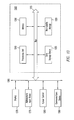
The business analyst's system, process designer 1210 is used to design new processes. There may be multiple process designers 1210 coupled to the system, although only one is shown here for simplicity. For one embodiment, the process designer 1210 may use a local copy of the process 1215 for editing. Alternatively, the process designer 1210 may access a sandbox 1255, over the network 1200, which provides a secure location to edit a process.
The best practice processes are available in a master process repository 155. The processes in the master process repository 155 are, for one embodiment, processes that were pre-created. For one embodiment, the best practice processes may further include processes created by business analysts that have been implemented. When the business analyst checks in a process, it is stored in the collection of processes in progress 135. These processes are waiting for implementation by the developer, on the developer's system 1220. The developer retrieves one or more processes from the collection 135, and implements them. The developer 1220 may have a local copy of the processes 1225 being edited, or may also use a separate sandbox 1255, connected to the Siebel system 1250.
For one embodiment, quality assurance system 1230 permits the testing of the implemented process. Once the developer, Q&A, and the business analyst all approve of a process, it can be made available by being placed into the available processes collection 1250. These available processes 1250 are used by process users 1260 throughout the company to automate certain processes, and to create uniformity of response throughout the corporation.
Note that although the above elements are described as “systems” they may be implemented on a single computer system. Alternatively, a single system may be distributed over multiple computers.
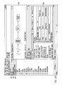
The data processing system illustrated in FIG. 13 includes a bus or other internal communication means 1315 for communicating information, and a processor 1310 coupled to the bus 1315 for processing information. The system further comprises a random access memory (RAM) or other volatile storage device 1350 (referred to as memory), coupled to bus 1315 for storing information and instructions to be executed by processor 1310. Main memory 1350 also may be used for storing temporary variables or other intermediate information during execution of instructions by processor 1310. The system also comprises a read only memory (ROM) and/or static storage device 1320 coupled to bus 1315 for storing static information and instructions for processor 1310, and a data storage device 1325 such as a magnetic disk or optical disk and its corresponding disk drive. Data storage device 1325 is coupled to bus 1315 for storing information and instructions.
The system may further be coupled to a display device 1370, such as a cathode ray tube (CRT) or a liquid crystal display (LCD) coupled to bus 1315 through bus 1365 for displaying information to a computer user. An alphanumeric input device 1375, including alphanumeric and other keys, may also be coupled to bus 1315 through bus 1365 for communicating information and command selections to processor 1310. An additional user input device is cursor control device 1380, such as a mouse, a trackball, stylus, or cursor direction keys coupled to bus 1315 through bus 1365 for communicating direction information and command selections to processor 1310, and for controlling cursor movement on display device 1370.
Another device, which may optionally be coupled to computer system 1300, is a communication device 1390 for accessing other nodes of a distributed system via a network. The communication device 1390 may include any of a number of commercially available networking peripheral devices such as those used for coupling to an Ethernet, token ring, Internet, or local or wide area network. The communication device 1390 may further be a null-modem connection, a wireless connection mechanism, or any other mechanism that provides connectivity between the computer system 1300 and the outside world. Note that any or all of the components of this system illustrated in FIG. 13 and associated hardware may be used in various embodiments of the present invention.
It will be appreciated by those of ordinary skill in the art that any configuration of the system may be used for various purposes according to the particular implementation. The control logic or software implementing the present invention can be stored in main memory 1350, mass storage device 1325, or other storage medium locally or remotely accessible to processor 1310.
It will be apparent to those of ordinary skill in the art that the system, method, and process described herein can be implemented as software stored in main memory 1350 or read only memory 1320 and executed by processor 1310. This control logic or software may also be resident on an article of manufacture comprising a computer readable medium having computer readable program code embodied therein and being readable by the mass storage device 1325 and for causing the processor 1310 to operate in accordance with the methods and teachings herein.
The present invention may also be embodied in a handheld or portable device containing a subset of the computer hardware components described above. For example, the handheld device may be configured to contain only the bus 1315, the processor 1310, and memory 1350 and/or 1325. The present invention may also be embodied in a special purpose appliance including a subset of the computer hardware components described above. For example, the appliance may include a processor 1310, a data storage device 1325, a bus 1315, and memory 1350, and only rudimentary communications mechanisms, such as a small touch-screen that permits the user to communicate in a basic manner with the device. In general, the more special-purpose the device is, the fewer of the elements need be present for the device to function. In some devices, communications with the user may be through a touch-based screen, or similar mechanism.
It will be appreciated by those of ordinary skill in the art that any configuration of the system may be used for various purposes according to the particular implementation. The control logic or software implementing the present invention can be stored on any machine-readable medium locally or remotely accessible to processor 1310. A machine-readable medium includes any mechanism for storing or transmitting information in a form readable by a machine (e.g. a computer). For example, a machine readable medium includes read-only memory (ROM), random access memory (RAM), magnetic disk storage media, optical storage media, flash memory devices, electrical, optical, acoustical or other forms of propagated signals (e.g. carrier waves, infrared signals, digital signals, etc.).
In the foregoing specification, the invention has been described with reference to specific exemplary embodiments thereof. It will, however, be evident that various modifications and changes may be made thereto without departing from the broader spirit and scope of the invention as set forth in the appended claims. The specification and drawings are, accordingly, to be regarded in an illustrative rather than a restrictive sense.
Claims (21)
1. A method comprising:
modeling a business process, wherein said modeling comprises
designing a process, wherein
said process represents a non-technical model of said business process,
said designing is performed using a non-technical user interface, and
said non-technical user interface is configured to permit design of said business process by a non-technical user, and
in response to an indication that said process is complete, transferring access to said process from said non-technical user interface to a technical user interface, wherein
said technical interface is configured to allow a technical user to implement said process, and
said transferring comprises
identifying an element, wherein
said element is an incompletely-defined element,
identifying a connector, wherein
said connector is an incompletely-defined connector,
said identifying of said element and said identifying of said connector permits completion of said incompletely-defined element and said incompletely-defined connector, and
configuring said technical user interface to be used to complete said incompletely-defined element and said incompletely-defined connector, and
implementing said process, wherein
said implementing implements said process as a technical model of said business process, and
said implementing is performed using said technical user interface.
2. The method of claim 1 , wherein said modeling further comprises:
editing said process, wherein
said editing is performed using said non-technical user interface.
3. The method of claim 2 , wherein
said process is an existing process.
4. The method of claim 3 , wherein said modeling further comprises:
selecting said existing process from a plurality of existing processes, wherein
a business process library comprises said existing processes.
5. The method of claim 1 , wherein said transferring comprises:
analyzing said process, wherein
said analyzing is performed in response to said process being checked-in from said non-technical user interface;
if a step is missing from said process, identifying said step as a missing step;
if said process comprises a new element, identifying said new element; and
if said process comprises a new connection, identifying said new connection.
6. The method of claim 5 , wherein said transferring further comprises:
if said missing step is identified, flagging said missing step;
if said new element is identified, flagging said new element; and
if said new connection is identified, flagging said new connection.
7. The method of claim 1 , wherein said implementing comprises:
displaying a systems view of said process;
determining whether an element needs to be added to said process; and
if said element needs to be added to said process, indicating said element needs to be added to said process.
8. The method of claim 1 , wherein said implementing comprises:
identifying an additional element, wherein
said additional element is a non-executable element;
identifying an additional connector, wherein
said additional connector is a non-executable connector; and
wherein
said identifying allows said non-executable element and said non-executable connector to be completed.
9. The method of claim 1 , wherein said modeling further comprises:
integrating said process with an external service.
10. The method of claim 9 , wherein said integrating comprises:
defining a source, wherein
said source defines a location of said external service, and
said source further defines an access mode for said external service;
defining a format, wherein
said format defines a first format for addressing said external service, and
said format further defines a second format to be used to transfer data from said external service; and
defining a transform, wherein
said transform defines a transformation between said first format and said second format.
11. The method of claim 1 , further comprising:
drilling down to a sub-process and to steps of the sub-process wherein
said drilling down enables displaying and editing the steps of the sub-process.
12. A non-transitory computer program product comprising:
a plurality of instructions, comprising
a first set of instructions, executable on a computer system, configured to model a business process, wherein
said first set of instructions comprise
a first subset of instructions, executable on said computer system, configured to design a process, wherein
said process represents a non-technical model of said business process,
said designing is performed using a non-technical user interface, and
said non-technical user interface is configured to permit design of said business process by a non-technical user, and
a second subset of instructions, executable on said computer system, configured to transfer access to said process from said non-technical user interface to a technical user interface, in response to an indication that said process is complete, wherein
said technical interface is configured to allow a technical user to implement said process, and
the transfer comprises
identifying an element, wherein
said element is an incompletely-defined element,
identifying a connector, wherein
said connector is an incompletely-defined connector, and
said identifying of said element and said identifying of said connector permits completion of said incompletely-defined element and said incompletely-defined connector, and
configuring the technical user interface to be used to complete said incompletely-defined element and said incompletely-defined connector, and
a third subset of instructions, executable on said computer system, configured to implement said process, wherein
said third set of instructions is configured to implement said process as a technical model of said business process, and
said implementing is performed using said technical user interface, and
a computer readable storage medium, wherein said instructions are encoded in said computer readable storage medium.
13. The non-transitory computer program product of claim 12 , wherein said further first set of instructions comprises:
a fourth subset of instructions, executable on said computer system, configured to edit said process, wherein
said editing is performed using said non-technical user interface, and
said process is an existing process; and
a fifth subset of instructions, executable on said computer system, configured to select said existing process from a plurality of existing processes, wherein a business process library comprises said existing processes.
14. The non-transitory computer program product of claim 12 , wherein said second subset of instructions comprises:
a first sub-subset of instructions, executable on said computer system, configured to analyzing said process, wherein
said first sub-subset of instructions are executed in response to said process being checked-in from said non-technical user interface;
a second sub-subset of instructions, executable on said computer system, configured to identify a step as a missing step, if said step is missing from said process;
a third sub-subset of instructions, executable on said computer system, configured to identify a new element, if said process comprises said new element; and
a fourth sub-subset of instructions, executable on said computer system, configured to identify a new connection, if said process comprises a new connection.
15. The non-transitory computer program product of claim 14 , wherein said second subset of instructions further comprises:
a fifth sub-subset of instructions, executable on said computer system, configured to flag said missing step, if said missing step is identified;
a sixth sub-subset of instructions, executable on said computer system, configured to flag said new element, if said new element is identified; and
a seventh sub-subset of instructions, executable on said computer system, configured to flag said new connection, if said new connection is identified.
16. The non-transitory computer program product of claim 12 , wherein said first set of instructions further comprises:
a fourth subset of instructions, executable on said computer system, configured to display a systems view of said process;
a fifth subset of instructions, executable on said computer system, configured to determine whether an element needs to be added to said process; and
a sixth subset of instructions, executable on said computer system, configured to indicate said element needs to be added to said process, if said element needs to be added to said process.
17. The non-transitory computer program product of claim 12 , wherein said first set of instructions further comprises:
a fourth subset of instructions, executable on said computer system, configured to integrate said process with an external service, wherein
said fourth subset of instructions comprises
a first sub-subset of instructions, executable on said computer system, configured to define a source, wherein
said source defines a location of said external service, and
said source further defines an access mode for said external service,
a second sub-subset of instructions, executable on said computer system, configured to define a format, wherein
said format defines a first format for addressing said external service, and
said format further defines a second format to be used to transfer data from said external service, and
a third sub-subset of instructions, executable on said computer system, configured to define a transform, wherein
said transform defines a transformation between said first format and said second format.
18. A computing system comprising:
a processor; and
a non-transitory computer-readable storage medium, wherein
said computer-readable storage medium and said processor are coupled to one another,
said computer-readable storage medium has instructions encoded therein, and
said instructions are configured to cause said processor to perform modeling of a business process by virtue of said instructions comprising
a non-technical interface module, wherein
said non-technical interface module is configured to be employed in designing a process,
said process represents a non-technical model of said business process, and
said non-technical interface module is configured to generate a non-technical user interface, and
said non-technical interface module is configured to permit design of said business process by a non-technical user, and
transfer and flagging logic, wherein
said transfer and flagging logic and said non-technical interface module are coupled to one another, and
said transfer and flagging logic is configured to transfer access to said process from said non-technical user interface to a technical user interface, in response to an indication that said process is complete, wherein
said technical interface is configured to allow a technical user to implement said process, and the transfer comprises
identifying an element, wherein
said element is an incompletely-defined element, identifying a connector, wherein
said connector is an incompletely-defined connector, and
wherein said identifying of said element and said identifying of said connector permits completion of said incompletely-defined element and said incompletely-defined connector, and
configuring the technical user interface to be used to complete said incompletely-defined element and said incompletely-defined connector, and
a technical interface module, wherein
said technical interface module and said transfer and flagging logic are coupled to one another,
said technical interface module is configured to implement said process as a technical model of said business process, and
said technical interface module is configured to generate said technical user interface.
19. The apparatus of claim 18 , wherein said instructions further comprise:
check-in logic, wherein
said check-in logic and said non-technical interface module are coupled to one another, and
said check-in logic is configured to generate said indication, upon said process being complete.
20. The apparatus of claim 19 , wherein said instructions further comprise:
validation logic, wherein
said validation logic is coupled to said check-in logic, said transfer and flagging logic, and said non-technical interface module, and
said validation logic is configured to analyze said process by virtue of being configured to determine
whether a step is missing from said process,
whether said process comprises a new element, and
whether said process comprises a new connection.
21. The apparatus of claim 18 , wherein said instructions further comprise:
integration logic, wherein
said integration logic and said technical interface module are coupled to one another, and
said integration logic is configured to integrate said process with an external service by virtual of being configured to
define a source, wherein
said source defines a location of said external service, and
said source further defines an access mode for said external service,
define a format, wherein
said format defines a first format for addressing said external service, and
said format further defines a second format to be used to transfer data from said external service, and
define a transform, wherein
said transform defines a transformation between said first format and said second format.
Priority Applications (2)
| Application Number | Priority Date | Filing Date | Title |
|---|---|---|---|
| US11/542,281 US8930833B2 (en) | 2002-12-31 | 2006-10-03 | Method and apparatus to present an integrated process modeler |
| US14/589,576 US20150127579A1 (en) | 2002-12-31 | 2015-01-05 | Method and apparatus to present an integrated process modeler |
Applications Claiming Priority (2)
| Application Number | Priority Date | Filing Date | Title |
|---|---|---|---|
| US10/334,922 US7117449B1 (en) | 2002-12-31 | 2002-12-31 | Method and apparatus to present an integrated process modeler |
| US11/542,281 US8930833B2 (en) | 2002-12-31 | 2006-10-03 | Method and apparatus to present an integrated process modeler |
Related Parent Applications (1)
| Application Number | Title | Priority Date | Filing Date |
|---|---|---|---|
| US10/334,922 Continuation US7117449B1 (en) | 2002-12-31 | 2002-12-31 | Method and apparatus to present an integrated process modeler |
Related Child Applications (1)
| Application Number | Title | Priority Date | Filing Date |
|---|---|---|---|
| US14/589,576 Continuation US20150127579A1 (en) | 2002-12-31 | 2015-01-05 | Method and apparatus to present an integrated process modeler |
Publications (2)
| Publication Number | Publication Date |
|---|---|
| US20070028179A1 US20070028179A1 (en) | 2007-02-01 |
| US8930833B2 true US8930833B2 (en) | 2015-01-06 |
Family
ID=37037426
Family Applications (3)
| Application Number | Title | Priority Date | Filing Date |
|---|---|---|---|
| US10/334,922 Expired - Lifetime US7117449B1 (en) | 2002-12-31 | 2002-12-31 | Method and apparatus to present an integrated process modeler |
| US11/542,281 Active 2027-07-02 US8930833B2 (en) | 2002-12-31 | 2006-10-03 | Method and apparatus to present an integrated process modeler |
| US14/589,576 Abandoned US20150127579A1 (en) | 2002-12-31 | 2015-01-05 | Method and apparatus to present an integrated process modeler |
Family Applications Before (1)
| Application Number | Title | Priority Date | Filing Date |
|---|---|---|---|
| US10/334,922 Expired - Lifetime US7117449B1 (en) | 2002-12-31 | 2002-12-31 | Method and apparatus to present an integrated process modeler |
Family Applications After (1)
| Application Number | Title | Priority Date | Filing Date |
|---|---|---|---|
| US14/589,576 Abandoned US20150127579A1 (en) | 2002-12-31 | 2015-01-05 | Method and apparatus to present an integrated process modeler |
Country Status (1)
| Country | Link |
|---|---|
| US (3) | US7117449B1 (en) |
Cited By (2)
| Publication number | Priority date | Publication date | Assignee | Title |
|---|---|---|---|---|
| US10838696B2 (en) | 2018-10-09 | 2020-11-17 | International Business Machines Corporation | Management of L-shaped swim lanes of variable heights and widths in a graphical editor used to represent multiple asynchronous process in the same view |
| US20210334714A1 (en) * | 2018-07-12 | 2021-10-28 | Nintex USA, Inc. | Business Designer |
Families Citing this family (66)
| Publication number | Priority date | Publication date | Assignee | Title |
|---|---|---|---|---|
| JP2002531890A (en) * | 1998-11-30 | 2002-09-24 | シーベル システムズ,インコーポレイティド | Development tools, methods and systems for client-server applications |
| US7051319B1 (en) * | 2001-03-27 | 2006-05-23 | Siebel Systems, Inc. | Method, system, and product for upgrading software objects using inherency |
| US7117449B1 (en) | 2002-12-31 | 2006-10-03 | Siebel Systems, Inc. | Method and apparatus to present an integrated process modeler |
| US7272818B2 (en) * | 2003-04-10 | 2007-09-18 | Microsoft Corporation | Creation of an object within an object hierarchy structure |
| US7496860B2 (en) * | 2004-06-30 | 2009-02-24 | United Technologies Corporation | Engineering standard work framework method and system |
| US8260755B2 (en) * | 2004-08-12 | 2012-09-04 | International Business Machines Corporation | Process-based documentation method and system |
| US20070240069A1 (en) * | 2006-04-11 | 2007-10-11 | Invensys Systems, Inc. | Appearance objects for configuring and graphically displaying programmed/configured process control |
| US8739068B2 (en) * | 2007-06-15 | 2014-05-27 | Microsoft Corporation | Dynamic user interface for in-diagram shape selection |
| US8762871B2 (en) * | 2008-02-03 | 2014-06-24 | Microsoft Corporation | Dynamic preview of diagram elements to be inserted into a diagram |
| US20120095585A1 (en) * | 2010-10-15 | 2012-04-19 | Invensys Systems Inc. | System and Method for Workflow Integration |
| US8745634B2 (en) | 2010-10-15 | 2014-06-03 | Invensys Systems, Inc. | System and method for integrated workflow scaling |
| US9411327B2 (en) | 2012-08-27 | 2016-08-09 | Johnson Controls Technology Company | Systems and methods for classifying data in building automation systems |
| US9996806B2 (en) * | 2012-09-27 | 2018-06-12 | International Business Machines Corporation | Modeling an enterprise |
| US9292263B2 (en) * | 2013-04-15 | 2016-03-22 | Massively Parallel Technologies, Inc. | System and method for embedding symbols within a visual representation of a software design to indicate completeness |
| GB2536513A (en) * | 2013-11-22 | 2016-09-21 | Hitachi Ltd | User interface generation system and generation method |
| JP6174825B2 (en) | 2015-01-16 | 2017-08-02 | 株式会社日立製作所 | Management system for creating services |
| US10534326B2 (en) | 2015-10-21 | 2020-01-14 | Johnson Controls Technology Company | Building automation system with integrated building information model |
| US11947785B2 (en) | 2016-01-22 | 2024-04-02 | Johnson Controls Technology Company | Building system with a building graph |
| US11268732B2 (en) | 2016-01-22 | 2022-03-08 | Johnson Controls Technology Company | Building energy management system with energy analytics |
| US11768004B2 (en) | 2016-03-31 | 2023-09-26 | Johnson Controls Tyco IP Holdings LLP | HVAC device registration in a distributed building management system |
| US10901373B2 (en) | 2017-06-15 | 2021-01-26 | Johnson Controls Technology Company | Building management system with artificial intelligence for unified agent based control of building subsystems |
| US10505756B2 (en) | 2017-02-10 | 2019-12-10 | Johnson Controls Technology Company | Building management system with space graphs |
| US10417451B2 (en) | 2017-09-27 | 2019-09-17 | Johnson Controls Technology Company | Building system with smart entity personal identifying information (PII) masking |
| US11774920B2 (en) | 2016-05-04 | 2023-10-03 | Johnson Controls Technology Company | Building system with user presentation composition based on building context |
| US11775261B2 (en) * | 2016-09-15 | 2023-10-03 | Oracle International Corporation | Dynamic process model palette |
| US10684033B2 (en) | 2017-01-06 | 2020-06-16 | Johnson Controls Technology Company | HVAC system with automated device pairing |
| US11900287B2 (en) | 2017-05-25 | 2024-02-13 | Johnson Controls Tyco IP Holdings LLP | Model predictive maintenance system with budgetary constraints |
| US11360447B2 (en) | 2017-02-10 | 2022-06-14 | Johnson Controls Technology Company | Building smart entity system with agent based communication and control |
| US20190361412A1 (en) | 2017-02-10 | 2019-11-28 | Johnson Controls Technology Company | Building smart entity system with agent based data ingestion and entity creation using time series data |
| US10515098B2 (en) | 2017-02-10 | 2019-12-24 | Johnson Controls Technology Company | Building management smart entity creation and maintenance using time series data |
| US11764991B2 (en) | 2017-02-10 | 2023-09-19 | Johnson Controls Technology Company | Building management system with identity management |
| US10169486B2 (en) | 2017-02-10 | 2019-01-01 | Johnson Controls Technology Company | Building management system with timeseries processing |
| WO2018175912A1 (en) | 2017-03-24 | 2018-09-27 | Johnson Controls Technology Company | Building management system with dynamic channel communication |
| US11327737B2 (en) | 2017-04-21 | 2022-05-10 | Johnson Controls Tyco IP Holdings LLP | Building management system with cloud management of gateway configurations |
| US20180324051A1 (en) * | 2017-05-05 | 2018-11-08 | Servicenow, Inc. | User interface for automated flows within a cloud based developmental platform |
| US10788229B2 (en) | 2017-05-10 | 2020-09-29 | Johnson Controls Technology Company | Building management system with a distributed blockchain database |
| US11022947B2 (en) | 2017-06-07 | 2021-06-01 | Johnson Controls Technology Company | Building energy optimization system with economic load demand response (ELDR) optimization and ELDR user interfaces |
| WO2019018304A1 (en) | 2017-07-17 | 2019-01-24 | Johnson Controls Technology Company | Systems and methods for agent based building simulation for optimal control |
| EP3655824A1 (en) | 2017-07-21 | 2020-05-27 | Johnson Controls Technology Company | Building management system with dynamic work order generation with adaptive diagnostic task details |
| US20190034066A1 (en) | 2017-07-27 | 2019-01-31 | Johnson Controls Technology Company | Building management system with central plantroom dashboards |
| US10962945B2 (en) | 2017-09-27 | 2021-03-30 | Johnson Controls Technology Company | Building management system with integration of data into smart entities |
| US11120012B2 (en) | 2017-09-27 | 2021-09-14 | Johnson Controls Tyco IP Holdings LLP | Web services platform with integration and interface of smart entities with enterprise applications |
| US10559181B2 (en) | 2017-09-27 | 2020-02-11 | Johnson Controls Technology Company | Building risk analysis system with risk combination for multiple threats |
| US11281169B2 (en) | 2017-11-15 | 2022-03-22 | Johnson Controls Tyco IP Holdings LLP | Building management system with point virtualization for online meters |
| US10809682B2 (en) | 2017-11-15 | 2020-10-20 | Johnson Controls Technology Company | Building management system with optimized processing of building system data |
| US11127235B2 (en) | 2017-11-22 | 2021-09-21 | Johnson Controls Tyco IP Holdings LLP | Building campus with integrated smart environment |
| US11954713B2 (en) | 2018-03-13 | 2024-04-09 | Johnson Controls Tyco IP Holdings LLP | Variable refrigerant flow system with electricity consumption apportionment |
| US11449813B2 (en) | 2018-04-13 | 2022-09-20 | Accenture Global Solutions Limited | Generating project deliverables using objects of a data model |
| US11016648B2 (en) | 2018-10-30 | 2021-05-25 | Johnson Controls Technology Company | Systems and methods for entity visualization and management with an entity node editor |
| US11927925B2 (en) | 2018-11-19 | 2024-03-12 | Johnson Controls Tyco IP Holdings LLP | Building system with a time correlated reliability data stream |
| US20200234220A1 (en) | 2019-01-18 | 2020-07-23 | Johnson Controls Technology Company | Smart building automation system with employee productivity features |
| US10788798B2 (en) | 2019-01-28 | 2020-09-29 | Johnson Controls Technology Company | Building management system with hybrid edge-cloud processing |
| US11894944B2 (en) | 2019-12-31 | 2024-02-06 | Johnson Controls Tyco IP Holdings LLP | Building data platform with an enrichment loop |
| US20210200792A1 (en) | 2019-12-31 | 2021-07-01 | Johnson Controls Technology Company | Building data platform with graph projections |
| US11537386B2 (en) | 2020-04-06 | 2022-12-27 | Johnson Controls Tyco IP Holdings LLP | Building system with dynamic configuration of network resources for 5G networks |
| US11874809B2 (en) | 2020-06-08 | 2024-01-16 | Johnson Controls Tyco IP Holdings LLP | Building system with naming schema encoding entity type and entity relationships |
| US11954154B2 (en) | 2020-09-30 | 2024-04-09 | Johnson Controls Tyco IP Holdings LLP | Building management system with semantic model integration |
| US11397773B2 (en) | 2020-09-30 | 2022-07-26 | Johnson Controls Tyco IP Holdings LLP | Building management system with semantic model integration |
| US20220138492A1 (en) | 2020-10-30 | 2022-05-05 | Johnson Controls Technology Company | Data preprocessing and refinement tool |
| JP2024511974A (en) | 2021-03-17 | 2024-03-18 | ジョンソン・コントロールズ・タイコ・アイピー・ホールディングス・エルエルピー | System and method for determining equipment energy waste |
| US11769066B2 (en) | 2021-11-17 | 2023-09-26 | Johnson Controls Tyco IP Holdings LLP | Building data platform with digital twin triggers and actions |
| US11899723B2 (en) | 2021-06-22 | 2024-02-13 | Johnson Controls Tyco IP Holdings LLP | Building data platform with context based twin function processing |
| US11796974B2 (en) | 2021-11-16 | 2023-10-24 | Johnson Controls Tyco IP Holdings LLP | Building data platform with schema extensibility for properties and tags of a digital twin |
| US11934966B2 (en) | 2021-11-17 | 2024-03-19 | Johnson Controls Tyco IP Holdings LLP | Building data platform with digital twin inferences |
| US11704311B2 (en) | 2021-11-24 | 2023-07-18 | Johnson Controls Tyco IP Holdings LLP | Building data platform with a distributed digital twin |
| US11714930B2 (en) | 2021-11-29 | 2023-08-01 | Johnson Controls Tyco IP Holdings LLP | Building data platform with digital twin based inferences and predictions for a graphical building model |
Citations (60)
| Publication number | Priority date | Publication date | Assignee | Title |
|---|---|---|---|---|
| US4656603A (en) * | 1984-03-01 | 1987-04-07 | The Cadware Group, Ltd. | Schematic diagram generating system using library of general purpose interactively selectable graphic primitives to create special applications icons |
| US5249300A (en) | 1990-04-27 | 1993-09-28 | Bachman Information Systems, Inc. | System and method of constructing models of complex business transactions using entity-set variables for ordered sets of references to user data |
| US5339438A (en) | 1991-12-12 | 1994-08-16 | International Business Machines Corporation | Version independence for object oriented programs |
| US5386568A (en) | 1992-12-01 | 1995-01-31 | Yamaha Corporation | Apparatus and method for linking software modules |
| US5493680A (en) | 1992-07-06 | 1996-02-20 | National Business Machines Corporation | Method for creating an object subclass with selective inheritance |
| US5642511A (en) * | 1994-12-16 | 1997-06-24 | International Business Machines Corporation | System and method for providing a visual application builder framework |
| US5651108A (en) | 1994-01-21 | 1997-07-22 | Borland International, Inc. | Development system with methods for visual inheritance and improved object reusability |
| EP0811193A2 (en) | 1995-02-22 | 1997-12-10 | Agust S. Egilsson | Graphical environment for managing and developing applications |
| US5715450A (en) | 1995-09-27 | 1998-02-03 | Siebel Systems, Inc. | Method of selecting and presenting data from a database using a query language to a user of a computer system |
| US5729253A (en) * | 1991-03-20 | 1998-03-17 | Hitachi, Ltd. | Method for inputting and acquiring requirement |
| US5732263A (en) | 1995-10-03 | 1998-03-24 | International Business Machines Corporation | Systems, methods and computer program products for generating and validating user defined object classes in an object oriented programming environment after build time |
| US5751909A (en) | 1994-03-17 | 1998-05-12 | Sybase, Inc. | Database system with methods for controlling object interaction by establishing database contracts between objects |
| US5768510A (en) | 1996-07-01 | 1998-06-16 | Sun Microsystems, Inc. | Object-oriented system, method and article of manufacture for a client-server application enabler system |
| US5787275A (en) | 1995-05-31 | 1998-07-28 | International Business Machines Corporation | Identifying multiple level class relationships in an object oriented system using icons and lines to represent class relationships |
| US5802514A (en) * | 1996-04-09 | 1998-09-01 | Vision Software Tools, Inc. | Automated client/server development tool using drag-and-drop metaphor |
| US5819092A (en) | 1994-11-08 | 1998-10-06 | Vermeer Technologies, Inc. | Online service development tool with fee setting capabilities |
| US5832274A (en) | 1996-10-09 | 1998-11-03 | Novell, Inc. | Method and system for migrating files from a first environment to a second environment |
| US5845128A (en) | 1996-02-20 | 1998-12-01 | Oracle Corporation | Automatically preserving application customizations during installation of a new software release |
| US5911075A (en) | 1997-03-31 | 1999-06-08 | International Business Machines Corporation | Query selection for a program development environment |
| US5970252A (en) | 1997-08-12 | 1999-10-19 | International Business Machines Corporation | Method and apparatus for loading components in a component system |
| US5978579A (en) | 1997-08-12 | 1999-11-02 | International Business Machines Corporation | Architecture for customizable component system |
| US6002867A (en) | 1996-10-24 | 1999-12-14 | Inprise Corporation | Development system with methods providing visual form inheritance |
| US6043815A (en) | 1997-09-30 | 2000-03-28 | The United States Of America As Represented By The Secretary Of The Navy | Method for using guiscript and providing a universal client device |
| WO2000033187A1 (en) | 1998-11-30 | 2000-06-08 | Siebel Systems, Inc. | Development tool, method, and system for client server appications |
| US6104874A (en) | 1996-10-15 | 2000-08-15 | International Business Machines Corporation | Object oriented framework mechanism for order processing including pre-defined extensible classes for defining an order processing environment |
| US6175948B1 (en) | 1998-02-05 | 2001-01-16 | Motorola, Inc. | Method and apparatus for a waveform compiler |
| US6182277B1 (en) | 1998-04-15 | 2001-01-30 | Oracle Corporation | Methods and apparatus for declarative programming techniques in an object oriented environment |
| US6233617B1 (en) | 1997-02-26 | 2001-05-15 | Siebel Systems, Inc. | Determining the visibility to a remote database client |
| US6249905B1 (en) | 1998-01-16 | 2001-06-19 | Kabushiki Kaisha Toshiba | Computerized accounting system implemented in an object-oriented programming environment |
| US6263498B1 (en) | 1998-12-03 | 2001-07-17 | International Business Machines Corporation | Method and apparatus for enabling server side distributed object modification |
| US6268853B1 (en) | 1999-09-30 | 2001-07-31 | Rockwell Technologies, L.L.C. | Data structure for use in enterprise controls |
| US6272537B1 (en) | 1997-11-17 | 2001-08-07 | Fujitsu Limited | Method for building element manager for a computer network element using a visual element manager builder process |
| US6292925B1 (en) | 1998-03-27 | 2001-09-18 | Xilinx, Inc. | Context-sensitive self implementing modules |
| US6367077B1 (en) | 1997-02-27 | 2002-04-02 | Siebel Systems, Inc. | Method of upgrading a software application in the presence of user modifications |
| US6370681B1 (en) | 1996-03-19 | 2002-04-09 | Massachusetts Institute Of Technology | Computer system and computer implemented process for representing software system descriptions and for generating executable computer programs and computer system configurations from software system descriptions |
| US6378003B1 (en) | 1993-04-05 | 2002-04-23 | International Business Machines Corporation | Method and system for deriving metaclasses in an object oriented system |
| US6415027B1 (en) | 1998-08-12 | 2002-07-02 | Bellsouth Intellectual Property Corporation | Networks, systems and methods for intelligently routing traffic within a telephone network |
| US6418450B2 (en) | 1998-01-26 | 2002-07-09 | International Business Machines Corporation | Data warehouse programs architecture |
| US6434740B1 (en) | 1998-07-15 | 2002-08-13 | International Business Machines Corporation | Apparatus and method for visual construction simplification |
| US6457164B1 (en) | 1998-03-27 | 2002-09-24 | Xilinx, Inc. | Hetergeneous method for determining module placement in FPGAs |
| US20020144174A1 (en) * | 2001-03-15 | 2002-10-03 | Nwabueze E. Kenneth | Methods for dynamically accessing , processing, and presenting data acquired from disparate data sources |
| US6526423B2 (en) * | 1998-11-12 | 2003-02-25 | Printable Technologies, Inc. | System and method for creating, generating and processing user-defined generic specs |
| US6567807B1 (en) | 2000-01-28 | 2003-05-20 | Ccbn.Com, Inc. | Investor relations event scheduling system and method |
| US6574630B1 (en) | 2000-01-28 | 2003-06-03 | Ccbn.Com, Inc. | Investor relations event notification system and method |
| US6574635B2 (en) | 1999-03-03 | 2003-06-03 | Siebel Systems, Inc. | Application instantiation based upon attributes and values stored in a meta data repository, including tiering of application layers objects and components |
| US6647394B1 (en) | 1999-06-08 | 2003-11-11 | International Business Machines Corporation | Doing business employing linked trees having retrievable embedded information |
| US6684388B1 (en) | 2000-08-22 | 2004-01-27 | International Business Machines Corporation | Method for generating platform independent, language specific computer code |
| US6693647B1 (en) | 1998-10-19 | 2004-02-17 | Lightsurf Technologies, Inc. | Method and apparatus for displaying notification that a color corrected image is being viewed |
| US6697825B1 (en) * | 1999-11-05 | 2004-02-24 | Decentrix Inc. | Method and apparatus for generating and modifying multiple instances of element of a web site |
| US6754885B1 (en) | 1999-05-17 | 2004-06-22 | Invensys Systems, Inc. | Methods and apparatus for controlling object appearance in a process control configuration system |
| US20050216421A1 (en) * | 1997-09-26 | 2005-09-29 | Mci. Inc. | Integrated business systems for web based telecommunications management |
| US7010523B2 (en) * | 2000-08-01 | 2006-03-07 | Oracle International Corporation | System and method for online analytical processing |
| US7051319B1 (en) | 2001-03-27 | 2006-05-23 | Siebel Systems, Inc. | Method, system, and product for upgrading software objects using inherency |
| US7089530B1 (en) | 1999-05-17 | 2006-08-08 | Invensys Systems, Inc. | Process control configuration system with connection validation and configuration |
| US7117449B1 (en) | 2002-12-31 | 2006-10-03 | Siebel Systems, Inc. | Method and apparatus to present an integrated process modeler |
| US7137100B2 (en) * | 2000-04-04 | 2006-11-14 | Jose Iborra | Automatic software production system |
| US7316000B2 (en) * | 2001-08-27 | 2008-01-01 | International Business Machines Corporation | Interactive agent for a topological multi-tier business application composer |
| US7370315B1 (en) * | 2000-11-21 | 2008-05-06 | Microsoft Corporation | Visual programming environment providing synchronization between source code and graphical component objects |
| US20090113384A1 (en) * | 2006-03-23 | 2009-04-30 | International Business Machines Corporation | System and apparatus for graphically building business rule conditions |
| US20100185478A1 (en) * | 2009-01-22 | 2010-07-22 | International Business Machines Corporation | Collaborative Working of Business Process Management Methods |
Family Cites Families (10)
| Publication number | Priority date | Publication date | Assignee | Title |
|---|---|---|---|---|
| US5991535A (en) * | 1996-07-03 | 1999-11-23 | Sun Microsystems, Inc. | Visual composition tool for constructing application programs using distributed objects on a distributed object network |
| US5913195A (en) * | 1996-12-27 | 1999-06-15 | Intervoice Limited Partnership | System and method for developing VRU voice dialogue |
| US6023578A (en) * | 1997-05-09 | 2000-02-08 | International Business Macines Corporation | Systems, methods and computer program products for generating an object oriented application for an object oriented environment |
| US6438594B1 (en) * | 1999-08-31 | 2002-08-20 | Accenture Llp | Delivering service to a client via a locally addressable interface |
| US6971065B2 (en) * | 2000-12-13 | 2005-11-29 | National Instruments Corporation | Automatically configuring a graphical program to publish or subscribe to data |
| AU2002328726A1 (en) * | 2001-09-28 | 2003-04-14 | Codagen Technologies Corp. | A system and method for managing architectural layers within a software model |
| US8639542B2 (en) | 2002-06-27 | 2014-01-28 | Siebel Systems, Inc. | Method and apparatus to facilitate development of a customer-specific business process model |
| US7257818B2 (en) * | 2002-08-29 | 2007-08-14 | Sap Aktiengesellschaft | Rapid application integration using functional atoms |
| US7500224B2 (en) * | 2002-11-01 | 2009-03-03 | Microsoft Corporation | Code blueprints |
| JP2006512670A (en) | 2002-12-31 | 2006-04-13 | シーベル・システムズ・インコーポレーテッド | Method and apparatus for an integrated process modeler |
-
2002
- 2002-12-31 US US10/334,922 patent/US7117449B1/en not_active Expired - Lifetime
-
2006
- 2006-10-03 US US11/542,281 patent/US8930833B2/en active Active
-
2015
- 2015-01-05 US US14/589,576 patent/US20150127579A1/en not_active Abandoned
Patent Citations (65)
| Publication number | Priority date | Publication date | Assignee | Title |
|---|---|---|---|---|
| US4656603A (en) * | 1984-03-01 | 1987-04-07 | The Cadware Group, Ltd. | Schematic diagram generating system using library of general purpose interactively selectable graphic primitives to create special applications icons |
| US5249300A (en) | 1990-04-27 | 1993-09-28 | Bachman Information Systems, Inc. | System and method of constructing models of complex business transactions using entity-set variables for ordered sets of references to user data |
| US5729253A (en) * | 1991-03-20 | 1998-03-17 | Hitachi, Ltd. | Method for inputting and acquiring requirement |
| US5339438A (en) | 1991-12-12 | 1994-08-16 | International Business Machines Corporation | Version independence for object oriented programs |
| US5493680A (en) | 1992-07-06 | 1996-02-20 | National Business Machines Corporation | Method for creating an object subclass with selective inheritance |
| US5386568A (en) | 1992-12-01 | 1995-01-31 | Yamaha Corporation | Apparatus and method for linking software modules |
| US6378003B1 (en) | 1993-04-05 | 2002-04-23 | International Business Machines Corporation | Method and system for deriving metaclasses in an object oriented system |
| US5651108A (en) | 1994-01-21 | 1997-07-22 | Borland International, Inc. | Development system with methods for visual inheritance and improved object reusability |
| US5751909A (en) | 1994-03-17 | 1998-05-12 | Sybase, Inc. | Database system with methods for controlling object interaction by establishing database contracts between objects |
| US5819092A (en) | 1994-11-08 | 1998-10-06 | Vermeer Technologies, Inc. | Online service development tool with fee setting capabilities |
| US5642511A (en) * | 1994-12-16 | 1997-06-24 | International Business Machines Corporation | System and method for providing a visual application builder framework |
| US6286017B1 (en) | 1995-02-22 | 2001-09-04 | EGILSSON áGUST SVERRIR | Graphical environment for managing and developing applications |
| EP0811193A2 (en) | 1995-02-22 | 1997-12-10 | Agust S. Egilsson | Graphical environment for managing and developing applications |
| US5787275A (en) | 1995-05-31 | 1998-07-28 | International Business Machines Corporation | Identifying multiple level class relationships in an object oriented system using icons and lines to represent class relationships |
| US5715450A (en) | 1995-09-27 | 1998-02-03 | Siebel Systems, Inc. | Method of selecting and presenting data from a database using a query language to a user of a computer system |
| US5732263A (en) | 1995-10-03 | 1998-03-24 | International Business Machines Corporation | Systems, methods and computer program products for generating and validating user defined object classes in an object oriented programming environment after build time |
| US5845128A (en) | 1996-02-20 | 1998-12-01 | Oracle Corporation | Automatically preserving application customizations during installation of a new software release |
| US6370681B1 (en) | 1996-03-19 | 2002-04-09 | Massachusetts Institute Of Technology | Computer system and computer implemented process for representing software system descriptions and for generating executable computer programs and computer system configurations from software system descriptions |
| US5802514A (en) * | 1996-04-09 | 1998-09-01 | Vision Software Tools, Inc. | Automated client/server development tool using drag-and-drop metaphor |
| US5768510A (en) | 1996-07-01 | 1998-06-16 | Sun Microsystems, Inc. | Object-oriented system, method and article of manufacture for a client-server application enabler system |
| US5832274A (en) | 1996-10-09 | 1998-11-03 | Novell, Inc. | Method and system for migrating files from a first environment to a second environment |
| US6104874A (en) | 1996-10-15 | 2000-08-15 | International Business Machines Corporation | Object oriented framework mechanism for order processing including pre-defined extensible classes for defining an order processing environment |
| US6002867A (en) | 1996-10-24 | 1999-12-14 | Inprise Corporation | Development system with methods providing visual form inheritance |
| US6233617B1 (en) | 1997-02-26 | 2001-05-15 | Siebel Systems, Inc. | Determining the visibility to a remote database client |
| US6367077B1 (en) | 1997-02-27 | 2002-04-02 | Siebel Systems, Inc. | Method of upgrading a software application in the presence of user modifications |
| US5911075A (en) | 1997-03-31 | 1999-06-08 | International Business Machines Corporation | Query selection for a program development environment |
| US5970252A (en) | 1997-08-12 | 1999-10-19 | International Business Machines Corporation | Method and apparatus for loading components in a component system |
| US5978579A (en) | 1997-08-12 | 1999-11-02 | International Business Machines Corporation | Architecture for customizable component system |
| US20050216421A1 (en) * | 1997-09-26 | 2005-09-29 | Mci. Inc. | Integrated business systems for web based telecommunications management |
| US6043815A (en) | 1997-09-30 | 2000-03-28 | The United States Of America As Represented By The Secretary Of The Navy | Method for using guiscript and providing a universal client device |
| US6272537B1 (en) | 1997-11-17 | 2001-08-07 | Fujitsu Limited | Method for building element manager for a computer network element using a visual element manager builder process |
| US6249905B1 (en) | 1998-01-16 | 2001-06-19 | Kabushiki Kaisha Toshiba | Computerized accounting system implemented in an object-oriented programming environment |
| US6418450B2 (en) | 1998-01-26 | 2002-07-09 | International Business Machines Corporation | Data warehouse programs architecture |
| US6175948B1 (en) | 1998-02-05 | 2001-01-16 | Motorola, Inc. | Method and apparatus for a waveform compiler |
| US6457164B1 (en) | 1998-03-27 | 2002-09-24 | Xilinx, Inc. | Hetergeneous method for determining module placement in FPGAs |
| US6292925B1 (en) | 1998-03-27 | 2001-09-18 | Xilinx, Inc. | Context-sensitive self implementing modules |
| US6182277B1 (en) | 1998-04-15 | 2001-01-30 | Oracle Corporation | Methods and apparatus for declarative programming techniques in an object oriented environment |
| US6434740B1 (en) | 1998-07-15 | 2002-08-13 | International Business Machines Corporation | Apparatus and method for visual construction simplification |
| US6415027B1 (en) | 1998-08-12 | 2002-07-02 | Bellsouth Intellectual Property Corporation | Networks, systems and methods for intelligently routing traffic within a telephone network |
| US6693647B1 (en) | 1998-10-19 | 2004-02-17 | Lightsurf Technologies, Inc. | Method and apparatus for displaying notification that a color corrected image is being viewed |
| US6526423B2 (en) * | 1998-11-12 | 2003-02-25 | Printable Technologies, Inc. | System and method for creating, generating and processing user-defined generic specs |
| US20070277153A1 (en) | 1998-11-30 | 2007-11-29 | Siebel Systems, Inc. | Development tool, method, and system for client server applications |
| US6553563B2 (en) | 1998-11-30 | 2003-04-22 | Siebel Systems, Inc. | Development tool, method, and system for client server applications |
| US7203938B2 (en) * | 1998-11-30 | 2007-04-10 | Siebel Systems, Inc. | Development tool, method, and system for client server applications |
| WO2000033187A1 (en) | 1998-11-30 | 2000-06-08 | Siebel Systems, Inc. | Development tool, method, and system for client server appications |
| US6263498B1 (en) | 1998-12-03 | 2001-07-17 | International Business Machines Corporation | Method and apparatus for enabling server side distributed object modification |
| US6574635B2 (en) | 1999-03-03 | 2003-06-03 | Siebel Systems, Inc. | Application instantiation based upon attributes and values stored in a meta data repository, including tiering of application layers objects and components |
| US7089530B1 (en) | 1999-05-17 | 2006-08-08 | Invensys Systems, Inc. | Process control configuration system with connection validation and configuration |
| US6754885B1 (en) | 1999-05-17 | 2004-06-22 | Invensys Systems, Inc. | Methods and apparatus for controlling object appearance in a process control configuration system |
| US6647394B1 (en) | 1999-06-08 | 2003-11-11 | International Business Machines Corporation | Doing business employing linked trees having retrievable embedded information |
| US6268853B1 (en) | 1999-09-30 | 2001-07-31 | Rockwell Technologies, L.L.C. | Data structure for use in enterprise controls |
| US6697825B1 (en) * | 1999-11-05 | 2004-02-24 | Decentrix Inc. | Method and apparatus for generating and modifying multiple instances of element of a web site |
| US6567807B1 (en) | 2000-01-28 | 2003-05-20 | Ccbn.Com, Inc. | Investor relations event scheduling system and method |
| US6574630B1 (en) | 2000-01-28 | 2003-06-03 | Ccbn.Com, Inc. | Investor relations event notification system and method |
| US7137100B2 (en) * | 2000-04-04 | 2006-11-14 | Jose Iborra | Automatic software production system |
| US7010523B2 (en) * | 2000-08-01 | 2006-03-07 | Oracle International Corporation | System and method for online analytical processing |
| US6684388B1 (en) | 2000-08-22 | 2004-01-27 | International Business Machines Corporation | Method for generating platform independent, language specific computer code |
| US7370315B1 (en) * | 2000-11-21 | 2008-05-06 | Microsoft Corporation | Visual programming environment providing synchronization between source code and graphical component objects |
| US20020144174A1 (en) * | 2001-03-15 | 2002-10-03 | Nwabueze E. Kenneth | Methods for dynamically accessing , processing, and presenting data acquired from disparate data sources |
| US20070226728A1 (en) | 2001-03-27 | 2007-09-27 | Thorson Peter A | Method, system, and product for upgrading software objects using inherency |
| US7051319B1 (en) | 2001-03-27 | 2006-05-23 | Siebel Systems, Inc. | Method, system, and product for upgrading software objects using inherency |
| US7316000B2 (en) * | 2001-08-27 | 2008-01-01 | International Business Machines Corporation | Interactive agent for a topological multi-tier business application composer |
| US7117449B1 (en) | 2002-12-31 | 2006-10-03 | Siebel Systems, Inc. | Method and apparatus to present an integrated process modeler |
| US20090113384A1 (en) * | 2006-03-23 | 2009-04-30 | International Business Machines Corporation | System and apparatus for graphically building business rule conditions |
| US20100185478A1 (en) * | 2009-01-22 | 2010-07-22 | International Business Machines Corporation | Collaborative Working of Business Process Management Methods |
Non-Patent Citations (11)
| Title |
|---|
| Benedicenti et al., "Reuse Libraries for Real Time Multimedia Over the Network," ACM SIGAPP, vol. 8, No. 1, Sep. 2000. |
| Bernstein, "Repositories and Object Oriented Databases," ACM, pp. 88-96, Mar. 1998. |
| Carnell, M., "Applet Designer," DBMS and Internet Systems, Jun. 1997. |
| Chen et al., "Exploring Performance Issues for a Clinical Database Organized Using an Entity-Attribute-Value Representation," Journal of American Medicine Information Association, vol. 7, No. 5, pp. 475-487, Mar. 2000. |
| Garlan et. al., "Architectural Mismatch or Why It's Hard to Build System Out of Existing Parts." ACM ICSE. pp. 179-185, 1995. |
| Henninger et al., "A Framework for Developing Experience Based Usability Guidelines,"ACM DIS. pp. 43-53, 1995. |
| Henninger et al., "An Organizational Learning Approach to Domain Analysis," ACM ICSE, pp. 95-104, 1995. |
| Henninger, "Supporting the Construction and Evolution of Component Repositories," ACM, pp. 279-288, 1996. |
| Sugumaran et al., "Identifying Software Components from Process Requirements Using Domain Model and Object Libraries," ACM, pp. 65-81, Jan. 1999. |
| Taulli, T., "Visual Basic Meets Java," Internet Java and ActiveX Advisor Magazine, Aug. 1997. |
| TV Objects Corporation. "Applet Designer Enterprise Edition," Jun. 1997. |
Cited By (4)
| Publication number | Priority date | Publication date | Assignee | Title |
|---|---|---|---|---|
| US20210334714A1 (en) * | 2018-07-12 | 2021-10-28 | Nintex USA, Inc. | Business Designer |
| US11640568B2 (en) * | 2018-07-12 | 2023-05-02 | Nintex USA, Inc. | Business designer |
| US20230267397A1 (en) * | 2018-07-12 | 2023-08-24 | Nintex USA, Inc. | Business Designer |
| US10838696B2 (en) | 2018-10-09 | 2020-11-17 | International Business Machines Corporation | Management of L-shaped swim lanes of variable heights and widths in a graphical editor used to represent multiple asynchronous process in the same view |
Also Published As
| Publication number | Publication date |
|---|---|
| US20150127579A1 (en) | 2015-05-07 |
| US7117449B1 (en) | 2006-10-03 |
| US20070028179A1 (en) | 2007-02-01 |
Similar Documents
| Publication | Publication Date | Title |
|---|---|---|
| US8930833B2 (en) | Method and apparatus to present an integrated process modeler | |
| US7251787B2 (en) | Method and apparatus for an integrated process modeller | |
| CA2937017C (en) | Integrated design application | |
| US8782598B2 (en) | Supporting a work packet request with a specifically tailored IDE | |
| US7493591B2 (en) | Methods and systems for animating a workflow and a project plan | |
| US20020062367A1 (en) | Opportunity tracking information system | |
| US20120116834A1 (en) | Hybrid task board and critical path method based project application | |
| WO2004061815A1 (en) | A method and apparatus for an integrated process modeller | |
| US20010052108A1 (en) | System, method and article of manufacturing for a development architecture framework | |
| CN111651680A (en) | Method and system for self-help generation of legal documents | |
| US20060047723A1 (en) | Custom database system and method of building the same | |
| US7877283B2 (en) | Multi-perspective business process configuration | |
| CN112686580B (en) | Workflow definition method and system capable of customizing flow | |
| US7707017B2 (en) | System modeling facilitating method and apparatus | |
| Christie | A practical guide to the technology and adoption of software process automation | |
| US20100011018A1 (en) | Custom database system and method of building the same | |
| Li | Jira 7 Essentials | |
| US20070198927A1 (en) | Computer-implemented systems and methods for an automated application interface | |
| Li | Jira 8 Essentials: Effective issue management and project tracking with the latest Jira features | |
| CN115759999A (en) | Business approval method | |
| Gould | Systems analysis and design | |
| Erskine | Microsoft System Center 2012 Service Manager Cookbook | |
| Heaton | Business intelligence cookbook: A project lifecycle approach using Oracle technology | |
| Christie et al. | An Investigation into Process-Centered Environments | |
| Basava | Supporting team performance—An empirical study of software teams, processes and tools to enhance software development |
Legal Events
| Date | Code | Title | Description |
|---|---|---|---|
| STCF | Information on status: patent grant |
Free format text: PATENTED CASE |
|
| CC | Certificate of correction | ||
| MAFP | Maintenance fee payment |
Free format text: PAYMENT OF MAINTENANCE FEE, 4TH YEAR, LARGE ENTITY (ORIGINAL EVENT CODE: M1551) Year of fee payment: 4 |
|
| MAFP | Maintenance fee payment |
Free format text: PAYMENT OF MAINTENANCE FEE, 8TH YEAR, LARGE ENTITY (ORIGINAL EVENT CODE: M1552); ENTITY STATUS OF PATENT OWNER: LARGE ENTITY Year of fee payment: 8 |