US8925773B2 - Holster assembly for a revolver and related locking device - Google Patents
Holster assembly for a revolver and related locking device Download PDFInfo
- Publication number
- US8925773B2 US8925773B2 US13/009,986 US201113009986A US8925773B2 US 8925773 B2 US8925773 B2 US 8925773B2 US 201113009986 A US201113009986 A US 201113009986A US 8925773 B2 US8925773 B2 US 8925773B2
- Authority
- US
- United States
- Prior art keywords
- revolver
- holster
- assembly
- shaped body
- Prior art date
- Legal status (The legal status is an assumption and is not a legal conclusion. Google has not performed a legal analysis and makes no representation as to the accuracy of the status listed.)
- Active, expires
Links
Images


Classifications
-
- F—MECHANICAL ENGINEERING; LIGHTING; HEATING; WEAPONS; BLASTING
- F41—WEAPONS
- F41C—SMALLARMS, e.g. PISTOLS, RIFLES; ACCESSORIES THEREFOR
- F41C33/00—Means for wearing or carrying smallarms
- F41C33/02—Holsters, i.e. cases for pistols having means for being carried or worn, e.g. at the belt or under the arm
- F41C33/0209—Pouch or pocket like containers for small arms covering all or most of the small arm
-
- F—MECHANICAL ENGINEERING; LIGHTING; HEATING; WEAPONS; BLASTING
- F41—WEAPONS
- F41C—SMALLARMS, e.g. PISTOLS, RIFLES; ACCESSORIES THEREFOR
- F41C33/00—Means for wearing or carrying smallarms
- F41C33/02—Holsters, i.e. cases for pistols having means for being carried or worn, e.g. at the belt or under the arm
- F41C33/0263—Holsters, i.e. cases for pistols having means for being carried or worn, e.g. at the belt or under the arm having a locking system for preventing unauthorized or accidental removal of the small arm from the holster
Definitions
- the present invention relates to firearm holsters, and more particularly, to holster assemblies with locking devices for revolvers.
- One locking device includes a saddle with engagement protrusions that is automatically biased into engagement with suitable surfaces of the firearm to inhibit withdrawal.
- the locking device includes an operating lever that extends out the holster and is operable to disengage the protrusions and allow firearm withdrawal.
- An example of this locking device can be seen in U.S. Pat. No. 7,694,860, dated Apr. 13, 2010, the contents of which are hereby incorporated by reference in their entirety. This type of locking device has proven very serviceable. However, additional developments and improvements are possible.
- a holster assembly includes a holster pocket with a locking device arranged therein and configured to accommodate insertion of a revolver, the locking device including a body and a operating lever pivotally mounted thereto.
- the operating lever is pivotable between a locked position, in which an engagement leg of the operating lever is in the path of a revolver cylinder, and an unlocked position, in which the operating lever is clear of the path of the revolver cylinder.
- FIG. 1 is a side view of a holster assembly for a revolver according to an embodiment of the present invention, including a holster pocket and locking device, with the revolver inserted therein;
- FIG. 2 is a perspective view of the holster assembly of FIG. 1 , with the revolver withdrawn;
- FIG. 3 is a perspective view of the holster assembly of FIG. 1 , with the holster pocket removed to show additional details of the locking device and a barrel positioning block assembly;
- FIG. 4 is a perspective view of the locking device of FIG. 1 ;
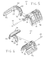
- FIG. 5 is an exploded perspective view of the locking device of FIG. 1 ;
- FIG. 6 is another exploded perspective view of the locking device of FIG. 1 ;
- FIG. 7 is an exploded perspective view of the barrel positioning block assembly of FIG. 3 ;
- FIG. 8 is a side view of the holster assembly of FIG. 1 , with the revolver inserted therein and partially cutaway to show a first configuration of the barrel positioning block assembly;
- FIG. 9 is a side view of the holster assembly of FIG. 1 , with another revolver inserted therein and partially cutaway to show a second configuration of the barrel positioning block assembly;
- FIG. 10 is a rear view of the holster assembly of FIG. 1 , in a unlocked position
- FIG. 11 is a rear view of the holster assembly of FIG. 10 , in a locked position.
- a holster assembly 10 for a revolver 12 includes a holster pocket 14 , a belt attachment plate 16 , a locking device 20 and a barrel positioning block assembly 22 .
- the belt attachment plate 16 , locking device 20 and barrel positioning block assembly 22 are releasably secured in the holster pocket 14 by a plurality of fastener elements 26 , for instance machine screws and corresponding threaded anchors.
- the holster pocket 14 and locking device 20 generally extend along an insertion axis 28 of the revolver 12 .
- the holster pocket 14 is preferably a rigidly molded structure dimensioned to generally conform to the portion of the revolver 12 inserted therein.
- the belt attachment plate 16 allows releasable mounting of the holster assembly 10 to a belt, harness or other connection point on a revolver user.
- the belt attachment plate 16 as well as the rest of the holster assembly 10 , are adapted for a right-hand draw arrangement. It will be appreciated that a left-handed draw arrangement is readily achieved using a mirror image of the holster assembly 10 .
- the locking device 20 is configured to automatically engage the revolver 12 upon insertion into the holster pocket 14 to inhibit withdrawal and is selectively operable to allow subsequent removal of the revolver 12 . More particularly, the locking device 20 is configured to automatically engage the cylinder 30 and/or the associated cylinder guard or load gate 32 (referred to generally as cylinder guard 32 ).
- the barrel positioning block assembly 22 is adapted to limit insertion of the revolver 12 into the holster pocket 14 and facilitate proper alignment between the revolver 12 and the locking device 20 .
- the locking device 20 includes an operating lever 40 and a generally U-shaped body 42 .
- the operating lever 40 and body 42 are pivotally connected by a pivot pin 44 inserted through aligned bores defined therein, such that the operating lever 40 may pivot relative to the body 42 about an axis generally parallel with the insertion axis 28 .
- the operating lever 40 has a generally central pivot portion 48 . On a first side of the pivot portion 48 , the operating lever 40 includes a revolver engagement leg 50 . On a second side of the pivot portion 48 , the operating lever 40 includes a biasing leg 52 and thumb tab 54 .
- the revolver engagement leg 50 has a blocking face 58 and a beveled face 60 formed on a lower end thereof.
- the biasing leg 52 is resiliently displaceable relative to the rest of the operating lever 40 .
- the thumb tab 54 extends generally in parallel with the insertion axis 28 and is dimensioned rearwardly out of the holster pocket 14 (see FIG. 1 ) to be operable by the user.
- the U-shaped body 42 has generally opposed first and second openings 64 , 66 defined therein.
- the first opening 64 accommodates the revolver engagement leg 50 therein.
- the biasing leg 52 and thumb tab 54 extend out from the second opening 66 .
- the relative dimensions of the operating lever 40 and the body 42 are such that, with the biasing leg 52 in a relaxed state, the blocking and engagement faces 58 , 60 of the engagement leg 50 will protrude inwardly from the first opening 64 (as seen in FIG. 4 ).
- the U-shaped body 42 further includes a biasing leg guide 70 and a positioning tab 72 extending outwardly therefrom.
- the guide 70 helps ensure proper positioning of the biasing leg 52 .
- the positioning tab 72 assists in maintaining a desired standoff distance between the holster pocket 14 (see FIG. 2 ) and the body 42 .
- the barrel positioning block assembly 22 includes a base positioning block 78 and at least one adapter insert 80 .
- the block 78 can be used with or without the insert 80 , depending on the type of revolver being used with the holster assembly 10 .
- the revolver 12 has an unenclosed ejector rod 82 .
- the base positioning block 78 is used together with the adapter insert 80 .
- the revolver 12 ′ has an ejector rod enclosure 82 ′ sufficiently large to use the block 78 without the insert 80 .
- the firearm 12 is inserted into the holster pocket 14 .
- the leading edge of the cylinder 30 contacts the beveled face 60 of the revolver engagement leg 50 , urging the engagement leg 50 outwardly, out of the path of the cylinder 30 , and causing the operating lever 40 to pivot, flexing the biasing leg 52 (see FIG. 10 ).
- the user manually depresses the thumb tab 54 .
- the engagement leg 50 is again pivoted outwardly, out of the path of the cylinder 30 and guard 32 , and the biasing leg 52 is flexed (see FIG. 10 ).
- the revolver 12 can then be freely withdrawn.
- the biasing leg 52 will again relax, urging the engagement leg 50 inwardly.
- the holster assembly 10 is then ready for automatic locking upon reinsertion of the revolver 12 .
Abstract
Description
Claims (20)
Priority Applications (1)
| Application Number | Priority Date | Filing Date | Title |
|---|---|---|---|
| US13/009,986 US8925773B2 (en) | 2010-01-20 | 2011-01-20 | Holster assembly for a revolver and related locking device |
Applications Claiming Priority (2)
| Application Number | Priority Date | Filing Date | Title |
|---|---|---|---|
| US29651310P | 2010-01-20 | 2010-01-20 | |
| US13/009,986 US8925773B2 (en) | 2010-01-20 | 2011-01-20 | Holster assembly for a revolver and related locking device |
Publications (2)
| Publication Number | Publication Date |
|---|---|
| US20110174850A1 US20110174850A1 (en) | 2011-07-21 |
| US8925773B2 true US8925773B2 (en) | 2015-01-06 |
Family
ID=44276828
Family Applications (1)
| Application Number | Title | Priority Date | Filing Date |
|---|---|---|---|
| US13/009,986 Active 2032-09-01 US8925773B2 (en) | 2010-01-20 | 2011-01-20 | Holster assembly for a revolver and related locking device |
Country Status (1)
| Country | Link |
|---|---|
| US (1) | US8925773B2 (en) |
Cited By (21)
| Publication number | Priority date | Publication date | Assignee | Title |
|---|---|---|---|---|
| US20140291363A1 (en) * | 2013-04-01 | 2014-10-02 | Norman E. Clifton, Jr. | Holster Including Trigger Guard Lock |
| USD784008S1 (en) * | 2015-01-16 | 2017-04-18 | Rogers Holster Co., Llc | Handgun holster |
| US9759515B2 (en) | 2012-08-17 | 2017-09-12 | Vista Outdoor Operations Llc | Holster |
| USD801041S1 (en) | 2016-03-22 | 2017-10-31 | Vista Outdoor Operations Llc | Holster |
| US10066902B2 (en) | 2009-11-09 | 2018-09-04 | Vista Outdoor Operations Llc | Holster having a rotatable lockout element |
| USD835400S1 (en) * | 2017-06-06 | 2018-12-11 | Franco Resca | Holster body |
| USD838102S1 (en) | 2017-01-17 | 2019-01-15 | Vista Outdoor Operations Llc | Holster |
| USD840147S1 (en) | 2017-07-17 | 2019-02-12 | Vista Outdoor Operations Llc | Holster |
| US10393477B1 (en) | 2006-11-16 | 2019-08-27 | Vista Outdoor Operations Llc | Retention holster for a firearm having an offset mounted accessory |
| USD860641S1 (en) | 2018-05-09 | 2019-09-24 | Vista Outdoor Operations Llc | Holster |
| US10436550B2 (en) | 2016-03-22 | 2019-10-08 | Vista Outdoor Operations Llc | Holster |
| US10619974B2 (en) | 2018-03-23 | 2020-04-14 | Vista Outdoor Operations Llc | Thumb-actuated locking holster |
| USD881557S1 (en) | 2019-01-18 | 2020-04-21 | Vista Outdoor Operations Llc | Holster |
| USD882247S1 (en) | 2015-03-20 | 2020-04-28 | Vista Outdoor Operations Llc | Holster |
| US10900744B1 (en) | 2019-01-18 | 2021-01-26 | Vista Outdoor Operations Llc | Holster |
| US10996024B2 (en) | 2018-03-23 | 2021-05-04 | Vista Outdoor Operations Llc | Thumb-actuated locking holster |
| US11333463B2 (en) * | 2020-05-26 | 2022-05-17 | U.S. Duty Gear, Inc. | Modular firearm holster safety retention assembly and method of operation |
| US11421959B2 (en) * | 2019-08-16 | 2022-08-23 | Edge-Works Manufacturing Company | Firearm holster |
| US11674776B2 (en) * | 2017-03-26 | 2023-06-13 | Sentry Solutions Products Group Llc | Overmolded / through-molded pouch |
| US11781831B2 (en) | 2020-06-12 | 2023-10-10 | Vista Outdoor Operations Llc | Thumb-actuated locking holster system |
| USD1022789S1 (en) | 2020-01-21 | 2024-04-16 | Vista Outdoor Operations Llc | Belt loop |
Families Citing this family (2)
| Publication number | Priority date | Publication date | Assignee | Title |
|---|---|---|---|---|
| ITFI20110099A1 (en) * | 2011-05-10 | 2012-11-11 | Radar Leather Division S R L | HOLSTER FOR PISTOLS WITH SAFETY LOCK TO ASSEMBLE IN THE EXHAUST OF THE WOODS |
| USD806382S1 (en) * | 2016-07-14 | 2018-01-02 | N82 Tactial, Inc. | Holster for a handgun |
Citations (8)
| Publication number | Priority date | Publication date | Assignee | Title |
|---|---|---|---|---|
| US20020134803A1 (en) * | 2001-03-23 | 2002-09-26 | Lowe Michael V. | Gun holster |
| US20040050887A1 (en) * | 1997-03-13 | 2004-03-18 | Peter Spielberger | Holster for handguns |
| US6732891B2 (en) * | 2001-08-30 | 2004-05-11 | Locklear, Iii Burney | Secure, quick-release handgun holster |
| US20060226185A1 (en) * | 2005-04-07 | 2006-10-12 | Fobus International Lltd. | Holster for a handgun |
| US20080121670A1 (en) * | 2006-10-27 | 2008-05-29 | Buress Steve M | Weapon Holster System |
| US7584875B2 (en) * | 2003-06-25 | 2009-09-08 | Tactical Design Labs, Inc. | Gun holster |
| US20090294496A1 (en) * | 2008-05-27 | 2009-12-03 | Gallagher Richard N | Gun holster with articulating spine |
| US7922050B2 (en) * | 2007-03-26 | 2011-04-12 | Bene Hacek Over S Miroslav | Handgun holster |
-
2011
- 2011-01-20 US US13/009,986 patent/US8925773B2/en active Active
Patent Citations (9)
| Publication number | Priority date | Publication date | Assignee | Title |
|---|---|---|---|---|
| US20040050887A1 (en) * | 1997-03-13 | 2004-03-18 | Peter Spielberger | Holster for handguns |
| US20020134803A1 (en) * | 2001-03-23 | 2002-09-26 | Lowe Michael V. | Gun holster |
| US6732891B2 (en) * | 2001-08-30 | 2004-05-11 | Locklear, Iii Burney | Secure, quick-release handgun holster |
| US7584875B2 (en) * | 2003-06-25 | 2009-09-08 | Tactical Design Labs, Inc. | Gun holster |
| US20060226185A1 (en) * | 2005-04-07 | 2006-10-12 | Fobus International Lltd. | Holster for a handgun |
| US20080121670A1 (en) * | 2006-10-27 | 2008-05-29 | Buress Steve M | Weapon Holster System |
| US7922050B2 (en) * | 2007-03-26 | 2011-04-12 | Bene Hacek Over S Miroslav | Handgun holster |
| US20090294496A1 (en) * | 2008-05-27 | 2009-12-03 | Gallagher Richard N | Gun holster with articulating spine |
| US8052018B2 (en) * | 2008-05-27 | 2011-11-08 | Gallagher Richard N | Gun holster with articulating spine |
Cited By (37)
| Publication number | Priority date | Publication date | Assignee | Title |
|---|---|---|---|---|
| US10393477B1 (en) | 2006-11-16 | 2019-08-27 | Vista Outdoor Operations Llc | Retention holster for a firearm having an offset mounted accessory |
| US10088273B2 (en) | 2009-11-09 | 2018-10-02 | Vista Outdoor Operations Llc | Holster having a slidable locking element |
| US11561064B2 (en) | 2009-11-09 | 2023-01-24 | Vista Outdoor Operations Llc | Holster having a removable lockout element |
| US10962325B2 (en) | 2009-11-09 | 2021-03-30 | Vista Outdoor Operations Llc | Holster having a removable lockout element |
| US10094637B2 (en) | 2009-11-09 | 2018-10-09 | Vista Outdoor Operations Llc | Holster having a removable lockout element |
| US10066902B2 (en) | 2009-11-09 | 2018-09-04 | Vista Outdoor Operations Llc | Holster having a rotatable lockout element |
| US10458748B2 (en) | 2012-08-17 | 2019-10-29 | Vista Outdoor Operations Llc | Holster |
| US9759515B2 (en) | 2012-08-17 | 2017-09-12 | Vista Outdoor Operations Llc | Holster |
| US20140291363A1 (en) * | 2013-04-01 | 2014-10-02 | Norman E. Clifton, Jr. | Holster Including Trigger Guard Lock |
| US9322612B2 (en) * | 2013-04-01 | 2016-04-26 | Safariland, Llc | Holster including trigger guard lock |
| USD784008S1 (en) * | 2015-01-16 | 2017-04-18 | Rogers Holster Co., Llc | Handgun holster |
| USD882247S1 (en) | 2015-03-20 | 2020-04-28 | Vista Outdoor Operations Llc | Holster |
| US11391539B2 (en) | 2016-03-22 | 2022-07-19 | Vista Outdoor Operations Llc | Holster |
| US10254078B2 (en) | 2016-03-22 | 2019-04-09 | Vista Outdoor Operations Llc | Holster |
| USD801041S1 (en) | 2016-03-22 | 2017-10-31 | Vista Outdoor Operations Llc | Holster |
| US10436550B2 (en) | 2016-03-22 | 2019-10-08 | Vista Outdoor Operations Llc | Holster |
| USD871057S1 (en) | 2016-03-22 | 2019-12-31 | Vista Outdoor Operations Llc | Holster |
| USD838102S1 (en) | 2017-01-17 | 2019-01-15 | Vista Outdoor Operations Llc | Holster |
| US11674776B2 (en) * | 2017-03-26 | 2023-06-13 | Sentry Solutions Products Group Llc | Overmolded / through-molded pouch |
| USD835400S1 (en) * | 2017-06-06 | 2018-12-11 | Franco Resca | Holster body |
| USD840147S1 (en) | 2017-07-17 | 2019-02-12 | Vista Outdoor Operations Llc | Holster |
| US11506466B2 (en) | 2018-03-23 | 2022-11-22 | Vista Outdoor Operations Llc | Thumb-actuated locking holster |
| US10619974B2 (en) | 2018-03-23 | 2020-04-14 | Vista Outdoor Operations Llc | Thumb-actuated locking holster |
| US11002511B2 (en) | 2018-03-23 | 2021-05-11 | Vista Outdoor Operations Llc | Thumb-actuated locking holster |
| US11725905B2 (en) | 2018-03-23 | 2023-08-15 | Vista Outdoor Operations Llc | Thumb-actuated locking holster |
| US10996024B2 (en) | 2018-03-23 | 2021-05-04 | Vista Outdoor Operations Llc | Thumb-actuated locking holster |
| USD860641S1 (en) | 2018-05-09 | 2019-09-24 | Vista Outdoor Operations Llc | Holster |
| US10900744B1 (en) | 2019-01-18 | 2021-01-26 | Vista Outdoor Operations Llc | Holster |
| USD881557S1 (en) | 2019-01-18 | 2020-04-21 | Vista Outdoor Operations Llc | Holster |
| US20220373294A1 (en) * | 2019-08-16 | 2022-11-24 | Edge-Works Manufacturing Company | Firearm holster |
| US11624584B2 (en) * | 2019-08-16 | 2023-04-11 | Edge-Works Manufacturing Company | Firearm holster |
| US11421959B2 (en) * | 2019-08-16 | 2022-08-23 | Edge-Works Manufacturing Company | Firearm holster |
| US20230235991A1 (en) * | 2019-08-16 | 2023-07-27 | Edge-Works Manufacturing Company | Firearm holster |
| US11906265B2 (en) * | 2019-08-16 | 2024-02-20 | Edge-Works Manufacturing Company | Firearm holster |
| USD1022789S1 (en) | 2020-01-21 | 2024-04-16 | Vista Outdoor Operations Llc | Belt loop |
| US11333463B2 (en) * | 2020-05-26 | 2022-05-17 | U.S. Duty Gear, Inc. | Modular firearm holster safety retention assembly and method of operation |
| US11781831B2 (en) | 2020-06-12 | 2023-10-10 | Vista Outdoor Operations Llc | Thumb-actuated locking holster system |
Also Published As
| Publication number | Publication date |
|---|---|
| US20110174850A1 (en) | 2011-07-21 |
Similar Documents
| Publication | Publication Date | Title |
|---|---|---|
| US8925773B2 (en) | Holster assembly for a revolver and related locking device | |
| US8910839B2 (en) | Locking device safety mechanism and related holster assembly | |
| US10254078B2 (en) | Holster | |
| US8851344B2 (en) | Holster | |
| US9057579B2 (en) | Quick draw gun holster | |
| US8985412B2 (en) | Quick draw gun holster | |
| US9057580B2 (en) | Quick draw gun holster with interactive accessory device | |
| US20210116209A1 (en) | Pistol chassis and firearm apparatus | |
| US9354012B2 (en) | Pistol grip bipod | |
| US9228802B2 (en) | Universal holster assembly | |
| US11391539B2 (en) | Holster | |
| US9816778B2 (en) | Holster for handgun | |
| CZ2007223A3 (en) | Handgun holster | |
| US9741981B2 (en) | Electronic apparatus having lock mechanism for locking battery accommodated in battery compartment | |
| US9791250B1 (en) | Quick release carrier for ammunition magazines | |
| US9228798B1 (en) | Rifle fore grip with mount for quick release of accessories | |
| CN110095017B (en) | Magazine sleeve | |
| US20100299905A1 (en) | Fast draw security holster | |
| US20190154423A1 (en) | Storage device for a magazine of a weapon | |
| US10267595B2 (en) | Holster for a handgun having a trigger guard and a barrel | |
| US9261326B1 (en) | Firearm docking systems | |
| CN210802217U (en) | Magazine sleeve | |
| EP3413009A1 (en) | Holster | |
| JP2013103307A (en) | Holster for potable tool |
Legal Events
| Date | Code | Title | Description |
|---|---|---|---|
| STCF | Information on status: patent grant |
Free format text: PATENTED CASE |
|
| AS | Assignment |
Owner name: SAFARILAND, LLC, FLORIDA Free format text: ASSIGNMENT OF ASSIGNORS INTEREST;ASSIGNOR:CLIFTON, NORMAN E., JR.;REEL/FRAME:036661/0987 Effective date: 20140916 |
|
| AS | Assignment |
Owner name: BANK OF AMERICA, N.A., AS AGENT, GEORGIA Free format text: SECURITY INTEREST;ASSIGNOR:SAFARILAND, LLC;REEL/FRAME:037262/0212 Effective date: 20151209 |
|
| AS | Assignment |
Owner name: WILMINGTON TRUST, NATIONAL ASSOCIATION, MINNESOTA Free format text: SECURITY INTEREST;ASSIGNORS:ROGERS HOLSTER CO., LLC;SAFARILAND, LLC;REEL/FRAME:037299/0927 Effective date: 20150929 |
|
| AS | Assignment |
Owner name: VIRTUS GROUP, LP, TEXAS Free format text: ASSIGNMENT OF INTELLECTUAL PROPERTY SECURITY AGREEMENTS;ASSIGNOR:WILMINGTON TRUST, NATIONAL ASSOCIATION;REEL/FRAME:040660/0873 Effective date: 20161118 |
|
| FEPP | Fee payment procedure |
Free format text: MAINTENANCE FEE REMINDER MAILED (ORIGINAL EVENT CODE: REM.); ENTITY STATUS OF PATENT OWNER: LARGE ENTITY |
|
| FEPP | Fee payment procedure |
Free format text: SURCHARGE FOR LATE PAYMENT, LARGE ENTITY (ORIGINAL EVENT CODE: M1554); ENTITY STATUS OF PATENT OWNER: LARGE ENTITY |
|
| MAFP | Maintenance fee payment |
Free format text: PAYMENT OF MAINTENANCE FEE, 4TH YEAR, LARGE ENTITY (ORIGINAL EVENT CODE: M1551); ENTITY STATUS OF PATENT OWNER: LARGE ENTITY Year of fee payment: 4 |
|
| AS | Assignment |
Owner name: GUGGENHEIM CREDIT SERVICES, LLC, NEW YORK Free format text: PATENT SECURITY INTEREST AGENT AGREEMENT;ASSIGNOR:VIRTUS GROUP, LP;REEL/FRAME:052628/0394 Effective date: 20200506 |
|
| AS | Assignment |
Owner name: GUGGENHEIM CREDIT SERVICES, LLC, AS AGENT, NEW YORK Free format text: PATENT SECURITY AGREEMENT;ASSIGNORS:MAUI ACQUISITION CORP.;SAFARILAND, LLC;SAFARILAND GLOBAL SOURCING, LLC;AND OTHERS;REEL/FRAME:054452/0405 Effective date: 20201117 Owner name: SAFARILAND, LLC, FLORIDA Free format text: TERMINATION AND RELEASE OF SECURITY INTEREST IN PATENT COLLATERAL;ASSIGNOR:GUGGENHEIM CREDIT SERVICES, LLC, AS AGENT;REEL/FRAME:054546/0619 Effective date: 20201117 Owner name: MED-ENG HOLDINGS ULC, FLORIDA Free format text: TERMINATION AND RELEASE OF SECURITY INTEREST IN PATENT COLLATERAL;ASSIGNOR:GUGGENHEIM CREDIT SERVICES, LLC, AS AGENT;REEL/FRAME:054546/0619 Effective date: 20201117 Owner name: PACIFIC SAFETY PRODUCTS INC., CANADA Free format text: TERMINATION AND RELEASE OF SECURITY INTEREST IN PATENT COLLATERAL;ASSIGNOR:GUGGENHEIM CREDIT SERVICES, LLC, AS AGENT;REEL/FRAME:054546/0619 Effective date: 20201117 Owner name: MED-ENG, LLC, NORTH CAROLINA Free format text: TERMINATION AND RELEASE OF SECURITY INTEREST IN PATENT COLLATERAL;ASSIGNOR:GUGGENHEIM CREDIT SERVICES, LLC, AS AGENT;REEL/FRAME:054546/0619 Effective date: 20201117 |
|
| AS | Assignment |
Owner name: PNC BANK, NATIONAL ASSOCIATION, AS ADMINISTRATIVE AGENT, PENNSYLVANIA Free format text: NOTICE OF GRANT OF SECURITY INTEREST IN PATENTS;ASSIGNOR:SAFARILAND, LLC;REEL/FRAME:057248/0904 Effective date: 20210820 |
|
| AS | Assignment |
Owner name: SAFARILAND, LLC, FLORIDA Free format text: RELEASE BY SECURED PARTY;ASSIGNOR:BANK OF AMERICA, N.A.;REEL/FRAME:057258/0180 Effective date: 20210820 |
|
| AS | Assignment |
Owner name: DEFENSE TECHNOLOGY, LLC, FLORIDA Free format text: RELEASE BY SECURED PARTY;ASSIGNOR:GUGGENHEIM CREDIT SERVICES, LLC, AS AGENT;REEL/FRAME:058014/0745 Effective date: 20210820 Owner name: PACIFIC SAFETY PRODUCTS INC., CANADA Free format text: RELEASE BY SECURED PARTY;ASSIGNOR:GUGGENHEIM CREDIT SERVICES, LLC, AS AGENT;REEL/FRAME:058014/0745 Effective date: 20210820 Owner name: MED-ENG HOLDINGS ULC, CANADA Free format text: RELEASE BY SECURED PARTY;ASSIGNOR:GUGGENHEIM CREDIT SERVICES, LLC, AS AGENT;REEL/FRAME:058014/0745 Effective date: 20210820 Owner name: GH ARMOR SYSTEMS, INC, FLORIDA Free format text: RELEASE BY SECURED PARTY;ASSIGNOR:GUGGENHEIM CREDIT SERVICES, LLC, AS AGENT;REEL/FRAME:058014/0745 Effective date: 20210820 Owner name: UNITED UNIFORM DISTRIBUTION, LLC, FLORIDA Free format text: RELEASE BY SECURED PARTY;ASSIGNOR:GUGGENHEIM CREDIT SERVICES, LLC, AS AGENT;REEL/FRAME:058014/0745 Effective date: 20210820 Owner name: SAFARILAND DISTRIBUTION, LLC, FLORIDA Free format text: RELEASE BY SECURED PARTY;ASSIGNOR:GUGGENHEIM CREDIT SERVICES, LLC, AS AGENT;REEL/FRAME:058014/0745 Effective date: 20210820 Owner name: LAWMEN'S DISTRIBUTION, LLC, NORTH CAROLINA Free format text: RELEASE BY SECURED PARTY;ASSIGNOR:GUGGENHEIM CREDIT SERVICES, LLC, AS AGENT;REEL/FRAME:058014/0745 Effective date: 20210820 Owner name: ATLANTIC TACTICAL, INC., PENNSYLVANIA Free format text: RELEASE BY SECURED PARTY;ASSIGNOR:GUGGENHEIM CREDIT SERVICES, LLC, AS AGENT;REEL/FRAME:058014/0745 Effective date: 20210820 Owner name: SENCAN HOLDINGS, LLC, FLORIDA Free format text: RELEASE BY SECURED PARTY;ASSIGNOR:GUGGENHEIM CREDIT SERVICES, LLC, AS AGENT;REEL/FRAME:058014/0745 Effective date: 20210820 Owner name: MED-ENG, LLC, NEW YORK Free format text: RELEASE BY SECURED PARTY;ASSIGNOR:GUGGENHEIM CREDIT SERVICES, LLC, AS AGENT;REEL/FRAME:058014/0745 Effective date: 20210820 Owner name: HORSEPOWER, LLC, FLORIDA Free format text: RELEASE BY SECURED PARTY;ASSIGNOR:GUGGENHEIM CREDIT SERVICES, LLC, AS AGENT;REEL/FRAME:058014/0745 Effective date: 20210820 Owner name: SAFARILAND GLOBAL SOURCING, LLC, FLORIDA Free format text: RELEASE BY SECURED PARTY;ASSIGNOR:GUGGENHEIM CREDIT SERVICES, LLC, AS AGENT;REEL/FRAME:058014/0745 Effective date: 20210820 Owner name: SAFARILAND, LLC, FLORIDA Free format text: RELEASE BY SECURED PARTY;ASSIGNOR:GUGGENHEIM CREDIT SERVICES, LLC, AS AGENT;REEL/FRAME:058014/0745 Effective date: 20210820 Owner name: CADRE HOLDINGS, INC., FLORIDA Free format text: RELEASE BY SECURED PARTY;ASSIGNOR:GUGGENHEIM CREDIT SERVICES, LLC, AS AGENT;REEL/FRAME:058014/0745 Effective date: 20210820 |
|
| MAFP | Maintenance fee payment |
Free format text: PAYMENT OF MAINTENANCE FEE, 8TH YEAR, LARGE ENTITY (ORIGINAL EVENT CODE: M1552); ENTITY STATUS OF PATENT OWNER: LARGE ENTITY Year of fee payment: 8 |