US8907222B2 - Adjustable cover for conductors and insulators - Google Patents
Adjustable cover for conductors and insulators Download PDFInfo
- Publication number
- US8907222B2 US8907222B2 US13/843,059 US201313843059A US8907222B2 US 8907222 B2 US8907222 B2 US 8907222B2 US 201313843059 A US201313843059 A US 201313843059A US 8907222 B2 US8907222 B2 US 8907222B2
- Authority
- US
- United States
- Prior art keywords
- cover
- section
- cover apparatus
- adjustable
- securing
- Prior art date
- Legal status (The legal status is an assumption and is not a legal conclusion. Google has not performed a legal analysis and makes no representation as to the accuracy of the status listed.)
- Active, expires
Links
Images


Classifications
-
- H—ELECTRICITY
- H02—GENERATION; CONVERSION OR DISTRIBUTION OF ELECTRIC POWER
- H02G—INSTALLATION OF ELECTRIC CABLES OR LINES, OR OF COMBINED OPTICAL AND ELECTRIC CABLES OR LINES
- H02G7/00—Overhead installations of electric lines or cables
-
- H—ELECTRICITY
- H02—GENERATION; CONVERSION OR DISTRIBUTION OF ELECTRIC POWER
- H02G—INSTALLATION OF ELECTRIC CABLES OR LINES, OR OF COMBINED OPTICAL AND ELECTRIC CABLES OR LINES
- H02G3/00—Installations of electric cables or lines or protective tubing therefor in or on buildings, equivalent structures or vehicles
- H02G3/02—Details
- H02G3/04—Protective tubing or conduits, e.g. cable ladders or cable troughs
- H02G3/0406—Details thereof
- H02G3/0418—Covers or lids; Their fastenings
-
- H—ELECTRICITY
- H01—ELECTRIC ELEMENTS
- H01B—CABLES; CONDUCTORS; INSULATORS; SELECTION OF MATERIALS FOR THEIR CONDUCTIVE, INSULATING OR DIELECTRIC PROPERTIES
- H01B17/00—Insulators or insulating bodies characterised by their form
-
- H—ELECTRICITY
- H02—GENERATION; CONVERSION OR DISTRIBUTION OF ELECTRIC POWER
- H02G—INSTALLATION OF ELECTRIC CABLES OR LINES, OR OF COMBINED OPTICAL AND ELECTRIC CABLES OR LINES
- H02G1/00—Methods or apparatus specially adapted for installing, maintaining, repairing or dismantling electric cables or lines
-
- B—PERFORMING OPERATIONS; TRANSPORTING
- B60—VEHICLES IN GENERAL
- B60M—POWER SUPPLY LINES, AND DEVICES ALONG RAILS, FOR ELECTRICALLY- PROPELLED VEHICLES
- B60M1/00—Power supply lines for contact with collector on vehicle
- B60M1/02—Details
- B60M1/04—Mechanical protection of line; Protection against contact by living beings
-
- Y—GENERAL TAGGING OF NEW TECHNOLOGICAL DEVELOPMENTS; GENERAL TAGGING OF CROSS-SECTIONAL TECHNOLOGIES SPANNING OVER SEVERAL SECTIONS OF THE IPC; TECHNICAL SUBJECTS COVERED BY FORMER USPC CROSS-REFERENCE ART COLLECTIONS [XRACs] AND DIGESTS
- Y10—TECHNICAL SUBJECTS COVERED BY FORMER USPC
- Y10T—TECHNICAL SUBJECTS COVERED BY FORMER US CLASSIFICATION
- Y10T29/00—Metal working
- Y10T29/49—Method of mechanical manufacture
- Y10T29/49002—Electrical device making
- Y10T29/49227—Insulator making
Definitions
- the instant application is generally directed towards a cover apparatus.
- the instant application is directed towards a cover apparatus for covering an electrical insulator and an electrical conductor.
- avian wildlife e.g., birds, raptors, eagles, etc.
- electrical insulators and energized conductors which can, among other things, compromise reliability and stability of a service offered by a utility and/or harm the wildlife.
- a cover apparatus for covering an electrical insulator and a conductor.
- the cover apparatus comprises one or more leg sections configured to cover a portion of the electrical conductor.
- a cover section is coupled to the one or more leg sections and is configured to cover a portion of the electrical insulator.
- the cover section comprises a body portion and an adjustable portion coupled to the body portion at a coupling location. The adjustable portion is configured to be adjusted such that a dimension of the adjustable portion is adjusted according to a dimension of the electrical insulator.
- a cover apparatus for covering an electrical insulator and a conductor.
- the cover apparatus comprises a first leg section configured to cover a first portion of the electrical conductor and a second leg section configured to cover a second portion of the electrical conductor.
- the cover apparatus comprises a cover section coupled to the first leg section and the second leg section and configured to cover a portion of the electrical insulator.
- the cover section comprises a body portion and an adjustable portion coupled to the body portion at a coupling location. The adjustable portion is configured to be adjusted such that a dimension of the adjustable portion is adjusted according to a dimension of the electrical insulator.
- a method of forming a cover apparatus for covering an electrical insulator and an electrical conductor comprises a method of forming a cover apparatus for covering an electrical insulator and an electrical conductor.
- the method comprises providing a cover section of the cover apparatus and one or more leg sections of the cover apparatus.
- the cover section is coupled to the one or more leg sections of the cover apparatus.
- the cover section is configured to cover a portion of the electrical insulator and the one or more leg sections are configured to cover a portion of the electrical conductor.
- the cover section comprises a body portion and an adjustable portion coupled to the body portion at a coupling location.
- the adjustable portion is configured to be adjusted such that a length of the adjustable portion, as measured from the coupling location to a distal end of the adjustable portion, is adjusted according to a dimension of the electrical insulator.
- the method comprises removing a separable section from the adjustable portion to reduce the length of the adjustable portion according to the dimension of the electrical insulator.
- FIG. 1 is a flow diagram illustrating an example method of forming a cover apparatus for covering an electrical insulator and electrical conductor
- FIG. 2 is an illustration of an example cover apparatus in a removed/detached state from an electrical structure
- FIG. 3 is an illustration of an example cover apparatus
- FIG. 4 is an illustration of an underside of an example cover apparatus
- FIG. 5 is an illustration of an example cover apparatus having a separable section of an adjustable portion removed
- FIG. 6 is an illustration of an example cover apparatus attached to an electrical structure
- FIG. 7 is an illustration of a second example cover apparatus
- FIG. 8 is an illustration of an underside of a second example cover apparatus.
- FIG. 9 is an illustration of a second example cover apparatus having a separable section of an adjustable portion removed
- FIG. 10 is an illustration of a second example cover apparatus attached to a second example electrical structure.
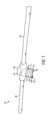
- FIG. 11 is an illustration of an example securing item for securing a cover apparatus to an electrical structure.
- FIG. 1 an example method 100 of forming a cover apparatus is illustrated.
- the method 100 can be used in association with some or all of the features illustrated in FIGS. 2 to 11 .
- the method 100 starts.
- a cover section of the cover apparatus is provided along with one or more leg sections of the cover apparatus.
- the cover section can be coupled to the one or more leg sections.
- the cover section can cover a portion of the electrical insulator and the one or more leg sections can cover a portion of the electrical conductor.
- the cover section can comprise a body portion and an adjustable portion coupled to the body portion at a coupling location.
- the adjustable portion can be adjusted such that a length of the adjustable portion, as measured from the coupling location to a distal end of the adjustable portion, is adjusted according to a dimension of the electrical insulator.
- a separable section can be removed from the adjustable portion to reduce the length of the adjustable portion according to the dimension of the electrical insulator.
- a cover apparatus 200 is illustrated for covering an electrical structure 202 , including an electrical insulator 208 and an electrical conductor 210 .
- the cover apparatus 200 is illustrated in a partially detached state from the electrical structure 202 so as to more clearly illustrate the features of the cover apparatus 200 and the electrical structure 202 .
- the cover apparatus 200 can cover the electrical structure 202 to provide at least some degree of protection to birds, raptors, eagles and/or other wildlife.
- the cover apparatus 200 can comprise a non-conductive material, such as plastics, composites, etc.
- the electrical structure 202 is somewhat generically/schematically illustrated, as the electrical structure 202 includes any number of sizes, shapes, structures, and configurations.
- the electrical structure 202 includes a utility pole 204 .
- the utility pole 204 can support power lines, cables, fiber optic cables, transformers, street lights, or any other type of equipment.
- the utility pole 204 can include materials such as wood, metal, concrete, composites (e.g., fiberglass, etc.) or the like.
- the utility pole 204 can support the electrical insulator 208 .
- the electrical insulator 208 can withstand operating voltage and electrical surges.
- the electrical insulator 208 can include any number of materials.
- the electrical insulator 208 includes porcelain, though other materials are envisioned, including ceramic, glass, polymers, or the like. While the utility pole 204 is illustrated to support one electrical insulator 208 in this example, the utility pole 204 could likewise support multiple electrical insulators 208 in other examples.
- the electrical insulator 208 can extend along a substantially vertical axis with respect to a surface of a material(s) into which the utility pole 204 is inserted, mounted, etc. (e.g., pavement, concrete, earth, etc.).
- the electrical insulator 208 can include one or more sheds 209 that project radially outwardly from a center of the electrical insulator 208 . Any number of sheds 209 can be provided (e.g., more than or less than as illustrated in FIG. 2 ). Likewise, the sheds 209 can include any number of dimensions, such as by being larger or smaller than as illustrated, being closer together, etc.
- the electrical insulator 208 can support at least one electrical conductor 210 .
- the electrical conductor 210 can allow for current to flow through the electrical conductor 210 so as to supply electricity.
- the electrical conductor 210 can include wires, cables, electrical lines, or nearly any type of structure capable of allowing for current to flow therethrough.
- the electrical conductor 210 is not limited to the illustrated dimensions, and could have a larger or smaller cross-sectional thickness than as illustrated. Likewise, the electrical conductor 210 can extend a longer distance than as illustrated, as only a portion of the electrical conductor 210 is illustrated.
- the electrical conductor 210 includes a first portion 212 and a second portion 214 .
- the first portion 212 of the electrical conductor 210 can be disposed on one side of the electrical insulator 208 while the second portion 214 of the electrical conductor 210 can be disposed on an opposing second side of the electrical insulator 208 .
- the first portion 212 and second portion 214 can extend a longer or shorter distance than as illustrated.
- the first portion 212 and second portion 214 can extend generally coaxially with each other along a linear axis. In other examples, however, the first portion 212 and second portion 214 can extend along axes that are non-coaxial with each other.
- the cover apparatus 200 can be applied to the electrical structure 202 so as to cover the electrical insulator 208 and the electrical conductor 210 .
- the directional arrows 220 are illustrated as being oriented in a downward direction, such as substantially perpendicular to a surface of a material(s) into which the utility pole 204 is inserted, mounted, etc. (e.g., pavement, concrete, earth, etc.).
- the cover apparatus 200 is not limited to being moved along the directional arrows 220 in the downward direction. Rather, the cover apparatus 200 can be applied to the electrical structure 202 from an angle relative to the surface of the material.
- the cover apparatus 200 is illustrated in more detail. While only a portion of the cover apparatus 200 is illustrated in this example for ease of illustration, the cover apparatus 200 can be longer or shorter in length than as illustrated, such as by having a length similar to that illustrated in FIG. 2 . In an example, the cover apparatus 200 can include a length of approximately 2 meters (e.g., ⁇ 80 inches). In other examples, however, the cover apparatus 200 could be longer or shorter, and is not limited to the dimensions disclosed herein.
- the cover apparatus 200 includes one or more leg sections.
- the one or more leg sections include a first leg section 300 and a second leg section 302 .
- the first leg section 300 can cover at least a first portion 212 of the electrical conductor 210 .
- the first leg section 300 can be generally hollow so as to support/receive structures therein.
- the first leg section 300 can receive the first portion 212 of the electrical conductor 210 therein. It is to be appreciated that the first leg section 300 can extend a longer or shorter distance than as illustrated herein, such that the first leg section 300 can cover a longer or shorter portion of the first portion 212 .
- the second leg section 302 can cover at least a second portion 214 of the electrical conductor 210 .
- the second leg section 302 can be generally hollow so as to support/receive structures therein.
- the second leg section 302 can receive the second portion 214 of the electrical conductor 210 therein. It is to be appreciated that the second leg section 302 can extend a longer or shorter distance than as illustrated herein, such that the second leg section 302 can cover a longer or shorter portion of the second portion 214 .
- the cover apparatus 200 includes a cover section 304 .
- the cover section 304 can be coupled to the one or more leg sections and cover a portion of the electrical insulator 208 and/or a portion of the electrical conductor 210 .
- the cover section 304 can be coupled to the first leg section 300 on one side and to the second leg section 302 on an opposing second side.
- the first leg section 300 and second leg section 302 can be coupled to the cover section 304 such that the first leg section 300 and second leg section 302 are generally coaxial with each other.
- the first leg section 300 and second leg section 302 can be coupled with respect to the cover section 304 at any degree of angles, such as by extending substantially non-coaxially with respect to each other, or the like.
- the cover section 304 can be integrally formed with the first leg section 300 and the second leg section 302 , such that the cover section 304 and the one or more leg sections are generally a composite structure.
- the cover section 304 and one or more leg sections can be separately attached to each other, such as by adhesives, mechanical fasteners, molding, etc.
- the cover section 304 can include a body portion 310 .
- the body portion 310 is a rounded, generally circularly shaped structure with a hollow center portion.
- the body portion 310 is sized and shaped so as to receive at least a portion of the electrical insulator 208 therein.
- the body portion 310 can be large enough so as to receive the electrical insulator 208 therein, such that the body portion 310 may be larger or slightly larger in size than the electrical insulator 208 .
- the body portion 310 is not limited to the generally circular shape that is illustrated. Rather, the body portion 310 can instead include quadrilateral shapes (e.g., square, rectangular, etc.), oval shapes, or the like.
- the body portion 310 can be larger or smaller in size than as illustrated, depending, at least in part, on the size(s) of the electrical insulator 208 and/or the electrical conductor 210 .
- the cover section 304 can include an adjustable portion 314 .
- the adjustable portion 314 can be coupled to the body portion 310 at a coupling location 316 .
- the adjustable portion 314 can extend between the coupling location 316 at one end to a distal end 318 at an opposing end.
- the adjustable portion 314 can be integrally formed with the body portion 310 , such that the adjustable portion 314 and the body portion 310 are generally a composite structure.
- the adjustable portion 314 and the body portion 310 can be separately attached to each other, such as by adhesives, mechanical fasteners, molding, etc.
- the adjustable portion 314 can be adjusted such that a dimension of the adjustable portion can be adjusted according to a dimension of the electrical insulator 208 .
- the dimension of the adjustable portion 314 corresponds to a length of the adjustable portion 314 as measured from the coupling location 316 to the distal end 318 of the adjustable portion 314 .
- the adjustable portion 314 can include one or more separable sections 330 . As illustrated, the separable sections 330 include a plurality of separable sections, though the adjustable portion 314 is not so limited.
- the adjustable portion 314 can include greater than or less than the number of separable sections 330 illustrated in FIG. 3 .
- the length of the adjustable portion 314 can be substantially perpendicular to an axis along which the electrical conductor 210 extends.
- the separable sections 330 can be spaced apart along the length of the adjustable portion 314 .
- the separable sections 330 can be separated from adjacent separable sections 330 by a separating mark 332 .
- the separating marks 332 can extend generally around the adjustable portion 314 .
- the separating marks 332 can define a weakened portion, such as by comprising a thinner wall portion than surrounding portions of the adjustable portion 314 .
- the separating marks 332 can include one or more perforations and/or punctures extending through the adjustable portion 314 .
- the separating marks 332 can allow for relatively easier removal of some of the separable sections 330 , such as by cutting or breaking along the separating marks 332 .
- the separating marks 332 are not so limited, however, and in other examples, need not include a weakened portion, perforation, or the like. Rather, the separating marks 332 can instead include a visual guide (e.g., drawn line, guide line, etc.) indicating where a user can cut, for example, to remove one or more of the separable sections 330 .
- a visual guide e.g., drawn line, guide line, etc.
- the separable sections 330 can comprise a first separable section 330 a separated from a second separable section 330 b by a first separating mark 332 a .
- a user can reduce the length of the adjustable portion 314 by removing the first separable section 330 a .
- the user can remove the first separable section 330 a , such as by making a cut, a break, or the like along the first separating mark 332 a .
- the user can similarly reduce the length of the adjustable portion 314 to a greater degree by removing more than one separable section 330 .
- the cover apparatus 200 includes a first wall 400 and a second wall 402 .
- the first wall 400 and second wall 402 can extend along and at least partially form the first leg section 300 , the cover section 304 , and second leg section 302 .
- the first wall 400 and second wall 402 extend generally parallel to each other and are spaced apart to define a hollow interior that is sized/shaped to receive the electrical insulator 208 and/or the electrical conductor 210 .
- the cover apparatus 200 can include one or more securing portions.
- the securing portions can include a first securing portion 403 in the first wall 400 and a second securing portion 404 in the second wall 402 .
- the first securing portion 403 and second securing portion 404 can be formed in either or both of the first leg section 300 or second leg section 302 .
- the first securing portion 403 and second securing portion 404 can, together, secure the cover apparatus 200 to the electrical conductor 210 .
- the cover apparatus 200 can include a total of eight securing portions (e.g., four (4) first securing portions 403 and four (4) second securing portions 404 ). In other examples, however, any number of securing portions can be provided.
- the one or more securing portions can include one or more attachment openings 410 .
- the attachment openings 410 include a first attachment opening 410 a and a second attachment opening 410 b .
- the first attachment opening 410 a can be formed in the first securing portion 403 while the second attachment opening 410 b can be formed in the second securing portion 404 .
- the attachment openings 410 can each include an opening extending through a pair of walls.
- the first attachment opening 410 a can extend through the first wall 400 while the second attachment opening 410 b can extend through the second wall 402 .
- the attachment openings 410 can receive a securing item 1100 (e.g., illustrated and described with respect to FIG. 11 ) to secure and maintain the electrical conductor 210 within the cover apparatus 200 .
- the securing item 1100 can be placed into the first attachment opening 410 a and the second attachment opening 410 b to couple the first securing portion 403 to the second securing portion 404 .
- the securing item 1100 can secure the cover apparatus 200 to the electrical conductor 210 .
- the attachment openings 410 can project inwardly towards a center of the cover apparatus 200 , so as to grip and hold the electrical conductor 210 therein.
- the walls may be somewhat rigid and may comprise indentations wherein the attachment openings 410 are formed.
- a space between opposing indentations in opposing walls may be slightly less than a diameter of the electrical conductor 210 such that opposing indentations apply a bias or (e.g., frictional) force against the electrical conductor when the electrical conductor 210 is situated in the space between opposing indentations.
- the cover apparatus 200 is (e.g., forcibly) pulled onto the electrical conductor 210 (e.g., ‘snapped’ down over, onto, etc. the electrical conductor) such that the electrical conductor 210 passes through the somewhat narrow spaces between opposing indentations.
- the indentations facilitate maintaining the cover apparatus 200 on the electrical conductor 210 .
- the attachment openings 410 can include a relief portion 412 formed in one of the walls adjacent one of the securing portions (e.g., first securing portion 403 or second securing portion 404 ).
- the relief portion 412 can be formed in the first wall 400 of the first leg section 300 adjacent to the first securing portion 403 .
- the relief portion 412 can define a cut, perforated, or punctured area, for example, surrounding the attachment openings 410 .
- the relief portion 412 is depicted somewhat generically/schematically in FIG. 4 .
- the relief portion 412 includes a quadrilateral shape (e.g., rectangular, square, etc.), though other shapes, such as circular, oval, etc. are envisioned.
- the relief portion 412 can allow for at least some degree of flexibility to an area surrounding the attachment openings 410 . Such flexibility can allow for bending/flexing when the cover apparatus 200 is pulled downwardly onto the electrical conductor 210 .
- the relief portion 412 can flex outwardly in response to contacting/engaging the electrical conductor 210 , before flexing back into place when the electrical conductor 210 is received within the cover apparatus 200 .
- the relief portion 412 can be formed in the first wall 400 surrounding the first attachment opening 410 a .
- the securing item 1100 can be inserted from the first wall 400 to the second wall 402 . In this manner, the relief portion 412 allows for flexing/bending in the first wall 400 as the cover apparatus 200 is installed on to the electrical conductor 210 but does not ‘flex away from’ the securing item 1100 during installation of the securing item.
- the cover apparatus 200 can include one or more gripping structures 420 located in the first leg section 300 and/or second leg section 302 .
- the gripping structures 420 can be supported by the walls.
- a first gripping structure 420 a can be supported by the first wall 400 while a second gripping structure 420 b can be supported by the second wall 402 .
- the gripping structures 420 can be positioned on opposing walls.
- a third gripping structure 420 c can be supported by the second wall 402 while a fourth gripping structure 420 d can be supported by the first wall 400 .
- the cover apparatus 200 is not specifically limited to the gripping structures 420 being located on alternating walls. Rather, in an example, the gripping structures 420 could instead be positioned on walls on the same side (e.g., the first wall 400 or the second wall 402 ).
- the gripping structures 420 include a gripping opening 422 .
- the gripping opening 422 can allow for a structure, such as an insulated pole (e.g., “hot stick”) or the like, to grip the gripping structures 420 through the gripping opening 422 .
- the insulated pole can more easily provide a downward, pulling force to the cover apparatus 200 on both sides of the electrical insulator 208 and electrical conductor 210 . This downward, pulling force is sufficient to cause the relief portion 412 to flex outwardly so as to receive the electrical conductor 210 within the cover apparatus 200 .
- the first gripping structure 420 a and the second gripping structure 420 can facilitate installation of the cover apparatus 200 onto the electrical conductor 210 .
- the adjustable portion 314 of the cover apparatus 200 can be adjusted such that a dimension of the adjustable portion 314 is adjusted according to a dimension of the electrical insulator 208 .
- the first separable section 330 a and second separable section 330 b can be removed (e.g., illustrated generically/schematically with arrowhead 500 ) from the adjustable portion 314 .
- the first separable section 330 a and second separable section 330 b can be separated from the adjustable portion 314 in any number of ways, such as by cutting, breaking, etc. along the separating mark 332 .
- the dimension, for example, the length, of the adjustable portion 314 can be adjusted and reduced as measured from the coupling location 316 to the distal end 318 of the adjustable portion 314 .
- the cover apparatus 200 can be fully attached to the electrical structure 202 .
- a portion of the cover apparatus 200 in association with the electrical insulator 208 and electrical conductor 210 is illustrated.
- the cover apparatus 200 can be larger than as illustrated in FIG. 6 , such as by having dimensions similar to the example illustrated in FIG. 2 .
- the cover apparatus 200 can be fully attached to the electrical structure 202 such that the cover section 304 extends substantially 360° around the portion of the electrical insulator 208 .
- the adjustable portion 314 can be dimensionally adjusted (e.g., before and/or after being attached to the electrical structure) to include any number of lengths.
- the adjustable portion 314 can be dimensionally adjusted such that the distal end 318 of the adjustable portion 314 is in proximity to the sheds 209 of the electrical insulator 208 .
- the distal end 318 can be in proximity to a first shed 209 a without covering or blocking the first shed 209 a .
- the adjustable portion 314 can extend a longer or shorter distance than as illustrated.
- the cover section 304 can extend along a substantially vertical axis. It will be appreciated that although the cover section extends substantially 360° around the portion of the electrical insulator 208 , at least some of the electrical insulator may remain accessible, such as through an underside of the cover section. That is, in some embodiments, the electrical insulator 208 is not completely enveloped by the cover apparatus 200 . Rather, at least some of the electrical insulator 208 may be accessed even when the cover apparatus 200 is installed.
- an insulated pole 600 can be used to attach the cover apparatus 200 to the electrical structure 202 .
- the insulated pole 600 is somewhat generically/schematically depicted, as the insulated pole 600 includes any number of sizes/shapes/constructions (e.g., longer or shorter in length, etc.).
- the insulated pole 600 can be handled and operated by a user.
- the insulated pole 600 includes a hooked portion 602 .
- the hooked portion 602 is disposed at an end of the insulated pole 600 .
- the hooked portion 602 is sized to be received within the gripping openings 422 of the gripping structure 420 .
- the hooked portion 602 of the insulated pole 600 is illustrated as engaging the first gripping structure 420 a , though the insulated pole 600 can similarly engage the second gripping structure 420 b , third gripping structure 420 c , and/or fourth gripping structure 420 d , etc.
- the user can exert a pulling force 604 on the cover apparatus 200 .
- the pulling force 604 can, in an example, be directed downwards.
- the pulling force 604 is sufficient to pull the cover apparatus 200 onto the electrical structure 202 (e.g., electrical conductor 210 , electrical insulator 208 , etc.).
- the second cover apparatus 700 can cover a second example electrical structure (e.g., illustrated in FIG. 10 ).
- the second cover apparatus 700 is illustrated separately from the electrical structure in this example to more clearly illustrate the features of the second cover apparatus 700 .
- the second cover apparatus 700 can cover the electrical structure to provide at least some degree of protection to birds, raptors, eagles, and/or other wildlife.
- the second cover apparatus 700 can comprise a non-conductive material, such as plastics, composites, etc.
- the second cover apparatus 700 includes the first leg section 300 and second leg section 302 .
- the first leg section 300 and second leg section 302 are generally identical to the first leg section 300 and second leg section 302 described above with respect to the cover apparatus 200 . As such, the first leg section 300 and second leg section 302 need not be described in detail again.
- the second cover apparatus 700 can include a second example cover section 704 .
- the second cover section 704 is similar to the cover section 304 but for the second cover section 704 extending along a generally horizontal axis relative to a plane of the material within which the utility pole is mounted.
- the second cover section 704 can cover an electrical insulator that extends along a generally horizontal axis relative to a plane of the material within which the utility pole is mounted.
- the second cover section 704 can be coupled to the one or more leg sections and cover a portion of the electrical insulator and/or a portion of the electrical conductor 210 .
- the second cover section 704 can be coupled to the first leg section 300 on one side and to the second leg section 302 on an opposing second side.
- the first leg section 300 and second leg section 302 can be coupled to the second cover section 704 such that the first leg section 300 and second leg section 302 are generally coaxial with each other.
- the first leg section 300 and second leg section 302 can be coupled with respect to the second cover section 704 at any degree of angles, such as by extending substantially non-coaxially with respect to each other, or the like.
- the second cover section 704 can be integrally formed with the first leg section 300 and the second leg section 302 , such that the second cover section 704 and the one or more leg sections are generally a composite structure.
- the second cover section 704 and one or more leg sections can be separately attached to each other, such as by adhesives, mechanical fasteners, molding, etc.
- the second cover section 704 can include a body portion 710 .
- the body portion 710 is a rounded, generally cylindrically shaped structure with a hollow center portion.
- the body portion 710 is sized and shaped so as to receive at least a portion of the electrical insulator therein.
- the body portion 710 can have a half-cylindrical shape in which a bottom half of the cylinder is removed.
- the body portion 710 can be large enough so as to receive the electrical insulator therein, such that the body portion 710 may be larger or slightly larger in size than the electrical insulator.
- the body portion 710 is not limited to the generally circular shape that is illustrated.
- the body portion 710 can instead include quadrilateral shapes (e.g., square, rectangular, etc.), oval shapes, or the like.
- the body portion 710 can be larger or smaller in size than as illustrated, depending, at least in part, on the size(s) of the electrical insulator and/or the electrical conductor.
- the second cover section 704 can include an adjustable portion 714 .
- the adjustable portion 714 can be coupled to the body portion 710 at a coupling location 716 .
- the adjustable portion 714 can extend between the coupling location 716 at one end to a distal end 718 at an opposing end.
- the adjustable portion 714 can extend along a generally horizontal axis with respect to the body portion 710 .
- the adjustable portion 714 can be integrally formed with the body portion 710 , such that the adjustable portion 714 and the body portion 710 are generally a composite structure.
- the adjustable portion 714 and the body portion 710 can be separately attached to each other, such as by adhesives, mechanical fasteners, molding, etc.
- the adjustable portion 714 can be adjusted such that a dimension of the adjustable portion 714 can be adjusted according to a dimension of the electrical insulator.
- the dimension of the adjustable portion 714 corresponds to a length of the adjustable portion 714 as measured from the coupling location 716 to the distal end 718 of the adjustable portion 714 .
- the adjustable portion 714 can include one or more separable sections 730 . As illustrated, the separable sections 730 include a plurality of separable sections, though the adjustable portion 714 is not so limited.
- the adjustable portion 714 can include greater than or less than the number of separable sections 730 illustrated in FIG. 7 .
- the length of the adjustable portion 714 can be substantially perpendicular to an axis along which the electrical conductor 210 extends.
- the separable sections 730 can be spaced apart along the length of the adjustable portion 714 .
- the separable sections 730 can be separated from adjacent separable sections 730 by a separating mark 732 .
- the separating marks 732 can extend generally around the adjustable portion 714 .
- the separating marks 732 can define a weakened portion, such as by comprising a thinner wall portion than surrounding portions of the adjustable portion 714 .
- the separating marks 732 can include one or more perforations and/or punctures extending through the adjustable portion 714 .
- the separating marks 732 can allow for relatively easier removal of some of the separable sections 730 , such as by cutting or breaking along the separating marks 732 .
- the separating marks 732 are not so limited, however, and in other examples, need not include a weakened portion, perforation, or the like. Rather, the separating marks 732 can instead include a visual guide (e.g., drawn line, guide line, etc.) indicating where a user can cut, for example, to remove one or more of the separable sections 730 .
- a visual guide e.g., drawn line, guide line, etc.
- the separable sections 730 can comprise a first separable section 730 a separated from a second separable section 730 b by a first separating mark 732 a .
- a user can reduce the length of the adjustable portion 714 by removing the first separable section 730 a .
- the user can remove the first separable section 730 a , such as by making a cut, a break, or the like along the first separating mark 732 a .
- the user can similarly reduce the length of the adjustable portion 714 to a greater degree by removing more than one separable section 730 .
- the second cover apparatus 700 can include the first wall 400 and second wall 402 .
- the first wall 400 and second wall 402 can be generally identical in size, shape, and construction as the first wall 400 and second wall 402 described above with respect to the cover apparatus 200 .
- the second cover apparatus 700 can include the securing portions and gripping structures 420 disposed in the first wall 400 and second wall 402 .
- the securing portions include the first securing portion 403 and second securing portion 404 .
- the first securing portion 403 and second securing portion 404 are generally identical as described above with respect to FIG. 4 , and need not be described in detail again.
- the gripping structures include the first gripping structure 420 a , second gripping structure 420 b , third gripping structure 420 c , and fourth gripping structure 420 d .
- the first gripping structure 420 a and second gripping structure 420 b are generally identical as described above with respect to FIG. 4 , and need not be described in detail again.
- the adjustable portion 714 of the second cover apparatus 700 can be adjusted such that a dimension of the adjustable portion 714 is adjusted according to a dimension of the electrical insulator.
- the first separable section 730 a and second separable section 730 b can be removed (e.g., illustrated generically/schematically with arrowhead 900 ) from the adjustable portion 714 .
- the first separable section 730 a and second separable section 730 b can be separated from the adjustable portion 714 in any number of ways, such as by cutting, breaking, etc. along the separating mark 732 .
- the dimension, for example, the length, of the adjustable portion 714 can be adjusted and reduced as measured from the coupling location 716 to the distal end 718 of the adjustable portion 714 .
- the second cover apparatus 700 can be fully attached to a second example electrical structure 1002 .
- the second electrical structure 1002 can include an electrical insulator 1008 .
- the electrical insulator 1008 can be supported by or attached to the utility pole 204 (e.g., illustrated in FIG. 2 ). As with the electrical insulator 208 of FIG. 2 , the electrical insulator 1008 can withstand operating voltage and electrical surges.
- the electrical insulator 1008 can include any number of materials, such as porcelain, ceramic, glass, polymers, or the like.
- the electrical insulator 1008 can extend in a substantially horizontal direction with respect to a surface of a material(s) into which the utility pole 204 is inserted, mounted, etc. (e.g., pavement, concrete, earth, etc.).
- the electrical insulator 1008 can include one or more sheds 1009 that project radially outwardly from a center of the electrical insulator 1008 .
- the electrical conductor 210 is generally identical to the electrical conductor 210 of FIG. 2 , and includes the first portion 212 and second portion 214 .
- the first portion 212 can be disposed on one side of the electrical insulator 1008 while the second portion 214 can be disposed on an opposing side.
- the first portion 212 and second portion 214 can extend generally coaxially, though in other examples, may extend non-coaxially with respect to each other.
- the second cover apparatus 700 can be fully attached to the second electrical structure 1002 such that the second cover apparatus 700 can extend substantially 180° around the portion of the electrical insulator 1008 .
- the adjustable portion 714 can be dimensionally adjusted (e.g., before and/or after being attached to the electrical structure) to include any number of lengths.
- the adjustable portion 714 can be dimensionally adjusted such that the distal end 718 of the adjustable portion 714 is in proximity to the sheds 1009 of the electrical insulator 1008 .
- the distal end 718 can be in proximity to a first shed 1009 a without covering or blocking the first shed 1009 a .
- the adjustable portion 714 can extend a longer or shorter distance than as illustrated.
- the insulated pole 600 can be used to attach the cover apparatus 200 to the second electrical structure 1002 .
- one or more securing items 1100 can attach the cover apparatus 200 to the electrical structure 202 or the second cover apparatus 700 to the second electrical structure 1002 . While only one securing item 1100 is illustrated in this example, the remaining securing items 1100 can be generally identical in size, structure, and construction. In operation, the securing items 1100 can be inserted through the attachment openings 410 .
- the securing item 1100 can include an insertion portion 1102 .
- the insertion portion 1102 is an elongated, substantially linearly extending protrusion that can be received within the attachment opening 410 .
- a cross-sectional size of the insertion portion 1102 can be slightly smaller than the cross-sectional size of the attachment openings 410 such that the insertion portion 1102 can be received therein.
- the insertion portion 1102 can include one or more ribs 1103 to assist in limiting inadvertent removal of the securing item 1100 from the attachment openings 410 .
- the ribs can engage, for example, edges of the attachment openings 410 to limit this removal.
- the insertion portion 1102 comprises any number of lengths, though in an example, the insertion portion 1102 can be long enough to pass through opposing attachment openings 410 in opposing walls of the cover apparatus 200 or the second cover apparatus 700 .
- the securing item 1100 can include an engagement portion 1104 disposed at an opposite end of the securing item 1100 relative to the insertion portion 1102 .
- the engagement portion 1104 is an elongated, substantially linearly extending protrusion.
- the engagement portion 1104 is not limited to the dimensions as illustrated, and in other examples, could be longer or shorter in length and/or include a larger or smaller cross-sectional size.
- the securing item 1100 can include a pin opening 1106 .
- the pin opening 1106 can be positioned between the insertion portion 1102 on one side and the engagement portion 1104 on an opposing second side.
- the pin opening 1106 in this example has a generally rounded shape, though other shapes are envisioned.
- the pin opening 1106 can have a larger or smaller size and/or could include other shapes, such as quadrilateral shapes (e.g., square, rectangular, etc.), oval shapes, or the like.
- the pin opening 1106 can receive the hooked portion 602 .
- the hooked portion 602 can be moved relative to a pole body 605 of the insulated pole 600 .
- the hooked portion 602 can be moved in the retracting direction 1108 while the pole body 605 can remain relatively stationary. This retraction can improve the gripping performance of the securing item 1100 by the insulated pole 600 .
- the engagement portion 1104 can contact and engage the pole body 605 . This engagement allows for the insertion portion 1102 to extend outwardly from the insulated pole 600 in a direction that is generally perpendicular to a direction along which the insulated pole 600 extends. Accordingly, inadvertent twisting/rotating of the securing item 1100 is limited, along with inadvertent release of the securing item 1100 from the hooked portion 602 .
- the insulated pole 600 can grip and hold the securing item 1100 , as illustrated.
- the hooked portion 602 is moved in the retracting direction 1108 until the engagement portion 1104 contacts and engages the pole body 605 .
- the insertion portion 1102 can extend outwardly from the pole body 605 , in a similar direction as illustrated in FIG. 11 .
- the user can then hold and manipulate the insulated pole 600 to insert the securing item 1100 into the attachment openings 410 .
- the configuration of the securing item such as by comprising the engagement portion 1104 , allows the securing item 1100 (e.g., as measured along a longest length of the securing item 1100 from a distal end of the engagement portion 1104 to a distal end of the insertion portion 1102 ) to be substantially perpendicular to a longest length of the pole body 605 when engaged by the insulated pole 600 .
- This arrangement of the securing item 1100 to the pole 600 allows a user to more easily insert the securing item 1100 into a pair of opposing attachment openings in opposing walls of the cover apparatus 200 or second cover apparatus 700 .
- a user standing on the surface of the material into which the utility pole is mounted may be able to thread the securing item into attachment openings 410 .
- the securing item 1100 may be able to move around and/or otherwise be less secure when engaged by the pole 600 , making it more difficult to insert the securing item 1100 into attachment openings 410 .
- the securing item 1100 may be substantially parallel to the pole 600 (e.g., longest length of securing item 1100 is parallel to (e.g., and extends further along) longest length of the pole body 605 ). In such an arrangement, it may be difficult for a user standing the surface of the material to insert the securing item 1100 into attachment openings 410 .
- the user may have to be elevated (e.g., via a bucket truck) so that an axis along the length of the pole 600 and the securing item 1100 aligns with an axis passing through a pair of opposing attachment openings in opposing walls of the cover apparatus 200 or second cover apparatus 700 to be able to insert the securing item 1100 into the pair of attachment openings.
- the engagement portion 1104 facilitates fewer complexities or requirements to install the securing item 1100 .
- the engagement portion is dimensioned to facilitate an arrangement of the securing item 1100 to the pole 600 to allow more user friendly installation of the securing item 1100 to the cover apparatus 200 and/or second cover apparatus 700 .
- the securing item 1100 can be moved along a securing direction 1150 such that the securing item 1100 can be inserted into the first attachment opening 410 a and second attachment opening 410 b .
- first attachment opening 410 a and second attachment opening 410 b are illustrated, together, somewhat generically/schematically as a circular opening. In operation, however, the first attachment opening 410 a and second attachment opening 410 b can be more similar in structure to the attachment openings illustrated and described previously.
- the insertion portion 1102 can facilitate placement of the securing item 1100 into the first attachment opening 410 a and second attachment opening 410 b.
- first,” “second,” or the like are not intended to imply a temporal aspect, a spatial aspect, an ordering, etc. Rather, such terms are merely used as identifiers, names, etc. for features, elements, items, etc.
- a first cover portion and a second cover portion generally correspond to cover portion A and cover portion B or two different or two identical cover portions or the same cover portions.
- exemplary is used herein to mean serving as an example, instance, illustration, etc., and not necessarily as advantageous.
- “or” is intended to mean an inclusive “or” rather than an exclusive “or”.
- “a” and “an” as used in this application are generally to be construed to mean “one or more” unless specified otherwise or clear from context to be directed to a singular form.
- at least one of A and B or the like generally means A or B or both A and B.
Abstract
Description
Claims (20)
Priority Applications (2)
| Application Number | Priority Date | Filing Date | Title |
|---|---|---|---|
| US13/843,059 US8907222B2 (en) | 2013-03-15 | 2013-03-15 | Adjustable cover for conductors and insulators |
| PCT/US2014/023380 WO2014150486A1 (en) | 2013-03-15 | 2014-03-11 | Adjustable cover for conductors and insulators |
Applications Claiming Priority (1)
| Application Number | Priority Date | Filing Date | Title |
|---|---|---|---|
| US13/843,059 US8907222B2 (en) | 2013-03-15 | 2013-03-15 | Adjustable cover for conductors and insulators |
Publications (2)
| Publication Number | Publication Date |
|---|---|
| US20140262434A1 US20140262434A1 (en) | 2014-09-18 |
| US8907222B2 true US8907222B2 (en) | 2014-12-09 |
Family
ID=50543662
Family Applications (1)
| Application Number | Title | Priority Date | Filing Date |
|---|---|---|---|
| US13/843,059 Active 2033-06-28 US8907222B2 (en) | 2013-03-15 | 2013-03-15 | Adjustable cover for conductors and insulators |
Country Status (2)
| Country | Link |
|---|---|
| US (1) | US8907222B2 (en) |
| WO (1) | WO2014150486A1 (en) |
Cited By (166)
| Publication number | Priority date | Publication date | Assignee | Title |
|---|---|---|---|---|
| US20150107892A1 (en) * | 2013-10-17 | 2015-04-23 | Eco Electrical Systems | Adjustable double insulator cover for electrical distribution systems |
| US9119127B1 (en) | 2012-12-05 | 2015-08-25 | At&T Intellectual Property I, Lp | Backhaul link for distributed antenna system |
| US9154966B2 (en) | 2013-11-06 | 2015-10-06 | At&T Intellectual Property I, Lp | Surface-wave communications and methods thereof |
| US9209902B2 (en) | 2013-12-10 | 2015-12-08 | At&T Intellectual Property I, L.P. | Quasi-optical coupler |
| US9312919B1 (en) | 2014-10-21 | 2016-04-12 | At&T Intellectual Property I, Lp | Transmission device with impairment compensation and methods for use therewith |
| US20160111863A1 (en) * | 2014-10-15 | 2016-04-21 | Marmon Utility, Llc | Wildlife Protective Cover having a Conductor/Insulator Guard and System for Power Distribution and Transmission Systems and Related Methods |
| US9461706B1 (en) | 2015-07-31 | 2016-10-04 | At&T Intellectual Property I, Lp | Method and apparatus for exchanging communication signals |
| US9490869B1 (en) | 2015-05-14 | 2016-11-08 | At&T Intellectual Property I, L.P. | Transmission medium having multiple cores and methods for use therewith |
| US9503189B2 (en) | 2014-10-10 | 2016-11-22 | At&T Intellectual Property I, L.P. | Method and apparatus for arranging communication sessions in a communication system |
| US9509415B1 (en) | 2015-06-25 | 2016-11-29 | At&T Intellectual Property I, L.P. | Methods and apparatus for inducing a fundamental wave mode on a transmission medium |
| US9520945B2 (en) | 2014-10-21 | 2016-12-13 | At&T Intellectual Property I, L.P. | Apparatus for providing communication services and methods thereof |
| US9525210B2 (en) | 2014-10-21 | 2016-12-20 | At&T Intellectual Property I, L.P. | Guided-wave transmission device with non-fundamental mode propagation and methods for use therewith |
| US9525524B2 (en) | 2013-05-31 | 2016-12-20 | At&T Intellectual Property I, L.P. | Remote distributed antenna system |
| US9531427B2 (en) | 2014-11-20 | 2016-12-27 | At&T Intellectual Property I, L.P. | Transmission device with mode division multiplexing and methods for use therewith |
| US9564947B2 (en) | 2014-10-21 | 2017-02-07 | At&T Intellectual Property I, L.P. | Guided-wave transmission device with diversity and methods for use therewith |
| US9577307B2 (en) | 2014-10-21 | 2017-02-21 | At&T Intellectual Property I, L.P. | Guided-wave transmission device and methods for use therewith |
| US9608740B2 (en) | 2015-07-15 | 2017-03-28 | At&T Intellectual Property I, L.P. | Method and apparatus for launching a wave mode that mitigates interference |
| US9608692B2 (en) | 2015-06-11 | 2017-03-28 | At&T Intellectual Property I, L.P. | Repeater and methods for use therewith |
| US9615269B2 (en) | 2014-10-02 | 2017-04-04 | At&T Intellectual Property I, L.P. | Method and apparatus that provides fault tolerance in a communication network |
| US9628116B2 (en) | 2015-07-14 | 2017-04-18 | At&T Intellectual Property I, L.P. | Apparatus and methods for transmitting wireless signals |
| US9628854B2 (en) | 2014-09-29 | 2017-04-18 | At&T Intellectual Property I, L.P. | Method and apparatus for distributing content in a communication network |
| US9640850B2 (en) | 2015-06-25 | 2017-05-02 | At&T Intellectual Property I, L.P. | Methods and apparatus for inducing a non-fundamental wave mode on a transmission medium |
| US9654173B2 (en) | 2014-11-20 | 2017-05-16 | At&T Intellectual Property I, L.P. | Apparatus for powering a communication device and methods thereof |
| US9653770B2 (en) | 2014-10-21 | 2017-05-16 | At&T Intellectual Property I, L.P. | Guided wave coupler, coupling module and methods for use therewith |
| US9667317B2 (en) | 2015-06-15 | 2017-05-30 | At&T Intellectual Property I, L.P. | Method and apparatus for providing security using network traffic adjustments |
| US9680670B2 (en) | 2014-11-20 | 2017-06-13 | At&T Intellectual Property I, L.P. | Transmission device with channel equalization and control and methods for use therewith |
| US9685992B2 (en) | 2014-10-03 | 2017-06-20 | At&T Intellectual Property I, L.P. | Circuit panel network and methods thereof |
| US9692101B2 (en) | 2014-08-26 | 2017-06-27 | At&T Intellectual Property I, L.P. | Guided wave couplers for coupling electromagnetic waves between a waveguide surface and a surface of a wire |
| US9705561B2 (en) | 2015-04-24 | 2017-07-11 | At&T Intellectual Property I, L.P. | Directional coupling device and methods for use therewith |
| US9705571B2 (en) | 2015-09-16 | 2017-07-11 | At&T Intellectual Property I, L.P. | Method and apparatus for use with a radio distributed antenna system |
| US9722318B2 (en) | 2015-07-14 | 2017-08-01 | At&T Intellectual Property I, L.P. | Method and apparatus for coupling an antenna to a device |
| US9729197B2 (en) | 2015-10-01 | 2017-08-08 | At&T Intellectual Property I, L.P. | Method and apparatus for communicating network management traffic over a network |
| US9735833B2 (en) | 2015-07-31 | 2017-08-15 | At&T Intellectual Property I, L.P. | Method and apparatus for communications management in a neighborhood network |
| US9742462B2 (en) | 2014-12-04 | 2017-08-22 | At&T Intellectual Property I, L.P. | Transmission medium and communication interfaces and methods for use therewith |
| US9749013B2 (en) | 2015-03-17 | 2017-08-29 | At&T Intellectual Property I, L.P. | Method and apparatus for reducing attenuation of electromagnetic waves guided by a transmission medium |
| US9748626B2 (en) | 2015-05-14 | 2017-08-29 | At&T Intellectual Property I, L.P. | Plurality of cables having different cross-sectional shapes which are bundled together to form a transmission medium |
| US9749053B2 (en) | 2015-07-23 | 2017-08-29 | At&T Intellectual Property I, L.P. | Node device, repeater and methods for use therewith |
| US9755697B2 (en) | 2014-09-15 | 2017-09-05 | At&T Intellectual Property I, L.P. | Method and apparatus for sensing a condition in a transmission medium of electromagnetic waves |
| US9762289B2 (en) | 2014-10-14 | 2017-09-12 | At&T Intellectual Property I, L.P. | Method and apparatus for transmitting or receiving signals in a transportation system |
| US9769020B2 (en) | 2014-10-21 | 2017-09-19 | At&T Intellectual Property I, L.P. | Method and apparatus for responding to events affecting communications in a communication network |
| US9769128B2 (en) | 2015-09-28 | 2017-09-19 | At&T Intellectual Property I, L.P. | Method and apparatus for encryption of communications over a network |
| US9780834B2 (en) | 2014-10-21 | 2017-10-03 | At&T Intellectual Property I, L.P. | Method and apparatus for transmitting electromagnetic waves |
| US9793955B2 (en) | 2015-04-24 | 2017-10-17 | At&T Intellectual Property I, Lp | Passive electrical coupling device and methods for use therewith |
| US9793951B2 (en) | 2015-07-15 | 2017-10-17 | At&T Intellectual Property I, L.P. | Method and apparatus for launching a wave mode that mitigates interference |
| US9793954B2 (en) | 2015-04-28 | 2017-10-17 | At&T Intellectual Property I, L.P. | Magnetic coupling device and methods for use therewith |
| US9800327B2 (en) | 2014-11-20 | 2017-10-24 | At&T Intellectual Property I, L.P. | Apparatus for controlling operations of a communication device and methods thereof |
| US9820146B2 (en) | 2015-06-12 | 2017-11-14 | At&T Intellectual Property I, L.P. | Method and apparatus for authentication and identity management of communicating devices |
| US9836957B2 (en) | 2015-07-14 | 2017-12-05 | At&T Intellectual Property I, L.P. | Method and apparatus for communicating with premises equipment |
| US9838896B1 (en) | 2016-12-09 | 2017-12-05 | At&T Intellectual Property I, L.P. | Method and apparatus for assessing network coverage |
| US9847850B2 (en) | 2014-10-14 | 2017-12-19 | At&T Intellectual Property I, L.P. | Method and apparatus for adjusting a mode of communication in a communication network |
| US9847566B2 (en) | 2015-07-14 | 2017-12-19 | At&T Intellectual Property I, L.P. | Method and apparatus for adjusting a field of a signal to mitigate interference |
| US9853342B2 (en) | 2015-07-14 | 2017-12-26 | At&T Intellectual Property I, L.P. | Dielectric transmission medium connector and methods for use therewith |
| US9860075B1 (en) | 2016-08-26 | 2018-01-02 | At&T Intellectual Property I, L.P. | Method and communication node for broadband distribution |
| US9866309B2 (en) | 2015-06-03 | 2018-01-09 | At&T Intellectual Property I, Lp | Host node device and methods for use therewith |
| US9865911B2 (en) | 2015-06-25 | 2018-01-09 | At&T Intellectual Property I, L.P. | Waveguide system for slot radiating first electromagnetic waves that are combined into a non-fundamental wave mode second electromagnetic wave on a transmission medium |
| US9871282B2 (en) | 2015-05-14 | 2018-01-16 | At&T Intellectual Property I, L.P. | At least one transmission medium having a dielectric surface that is covered at least in part by a second dielectric |
| US9871283B2 (en) | 2015-07-23 | 2018-01-16 | At&T Intellectual Property I, Lp | Transmission medium having a dielectric core comprised of plural members connected by a ball and socket configuration |
| US9876571B2 (en) | 2015-02-20 | 2018-01-23 | At&T Intellectual Property I, Lp | Guided-wave transmission device with non-fundamental mode propagation and methods for use therewith |
| US9876605B1 (en) | 2016-10-21 | 2018-01-23 | At&T Intellectual Property I, L.P. | Launcher and coupling system to support desired guided wave mode |
| US9876264B2 (en) | 2015-10-02 | 2018-01-23 | At&T Intellectual Property I, Lp | Communication system, guided wave switch and methods for use therewith |
| US9882257B2 (en) | 2015-07-14 | 2018-01-30 | At&T Intellectual Property I, L.P. | Method and apparatus for launching a wave mode that mitigates interference |
| US9882277B2 (en) | 2015-10-02 | 2018-01-30 | At&T Intellectual Property I, Lp | Communication device and antenna assembly with actuated gimbal mount |
| US9893795B1 (en) | 2016-12-07 | 2018-02-13 | At&T Intellectual Property I, Lp | Method and repeater for broadband distribution |
| US9904535B2 (en) | 2015-09-14 | 2018-02-27 | At&T Intellectual Property I, L.P. | Method and apparatus for distributing software |
| US9906269B2 (en) | 2014-09-17 | 2018-02-27 | At&T Intellectual Property I, L.P. | Monitoring and mitigating conditions in a communication network |
| US9912381B2 (en) | 2015-06-03 | 2018-03-06 | At&T Intellectual Property I, Lp | Network termination and methods for use therewith |
| US9911020B1 (en) | 2016-12-08 | 2018-03-06 | At&T Intellectual Property I, L.P. | Method and apparatus for tracking via a radio frequency identification device |
| US9912419B1 (en) | 2016-08-24 | 2018-03-06 | At&T Intellectual Property I, L.P. | Method and apparatus for managing a fault in a distributed antenna system |
| US9913139B2 (en) | 2015-06-09 | 2018-03-06 | At&T Intellectual Property I, L.P. | Signal fingerprinting for authentication of communicating devices |
| US9912027B2 (en) | 2015-07-23 | 2018-03-06 | At&T Intellectual Property I, L.P. | Method and apparatus for exchanging communication signals |
| US9917341B2 (en) | 2015-05-27 | 2018-03-13 | At&T Intellectual Property I, L.P. | Apparatus and method for launching electromagnetic waves and for modifying radial dimensions of the propagating electromagnetic waves |
| US9927517B1 (en) | 2016-12-06 | 2018-03-27 | At&T Intellectual Property I, L.P. | Apparatus and methods for sensing rainfall |
| US9948354B2 (en) | 2015-04-28 | 2018-04-17 | At&T Intellectual Property I, L.P. | Magnetic coupling device with reflective plate and methods for use therewith |
| US9948333B2 (en) | 2015-07-23 | 2018-04-17 | At&T Intellectual Property I, L.P. | Method and apparatus for wireless communications to mitigate interference |
| US9954287B2 (en) | 2014-11-20 | 2018-04-24 | At&T Intellectual Property I, L.P. | Apparatus for converting wireless signals and electromagnetic waves and methods thereof |
| US9967173B2 (en) | 2015-07-31 | 2018-05-08 | At&T Intellectual Property I, L.P. | Method and apparatus for authentication and identity management of communicating devices |
| US9973940B1 (en) | 2017-02-27 | 2018-05-15 | At&T Intellectual Property I, L.P. | Apparatus and methods for dynamic impedance matching of a guided wave launcher |
| US9991580B2 (en) | 2016-10-21 | 2018-06-05 | At&T Intellectual Property I, L.P. | Launcher and coupling system for guided wave mode cancellation |
| US9999038B2 (en) | 2013-05-31 | 2018-06-12 | At&T Intellectual Property I, L.P. | Remote distributed antenna system |
| US9997819B2 (en) | 2015-06-09 | 2018-06-12 | At&T Intellectual Property I, L.P. | Transmission medium and method for facilitating propagation of electromagnetic waves via a core |
| US9998870B1 (en) | 2016-12-08 | 2018-06-12 | At&T Intellectual Property I, L.P. | Method and apparatus for proximity sensing |
| US10009901B2 (en) | 2015-09-16 | 2018-06-26 | At&T Intellectual Property I, L.P. | Method, apparatus, and computer-readable storage medium for managing utilization of wireless resources between base stations |
| US10009067B2 (en) | 2014-12-04 | 2018-06-26 | At&T Intellectual Property I, L.P. | Method and apparatus for configuring a communication interface |
| US10009063B2 (en) | 2015-09-16 | 2018-06-26 | At&T Intellectual Property I, L.P. | Method and apparatus for use with a radio distributed antenna system having an out-of-band reference signal |
| US10009065B2 (en) | 2012-12-05 | 2018-06-26 | At&T Intellectual Property I, L.P. | Backhaul link for distributed antenna system |
| US10020844B2 (en) | 2016-12-06 | 2018-07-10 | T&T Intellectual Property I, L.P. | Method and apparatus for broadcast communication via guided waves |
| US10020587B2 (en) | 2015-07-31 | 2018-07-10 | At&T Intellectual Property I, L.P. | Radial antenna and methods for use therewith |
| US10027397B2 (en) | 2016-12-07 | 2018-07-17 | At&T Intellectual Property I, L.P. | Distributed antenna system and methods for use therewith |
| US10033108B2 (en) | 2015-07-14 | 2018-07-24 | At&T Intellectual Property I, L.P. | Apparatus and methods for generating an electromagnetic wave having a wave mode that mitigates interference |
| US10033107B2 (en) | 2015-07-14 | 2018-07-24 | At&T Intellectual Property I, L.P. | Method and apparatus for coupling an antenna to a device |
| US10044409B2 (en) | 2015-07-14 | 2018-08-07 | At&T Intellectual Property I, L.P. | Transmission medium and methods for use therewith |
| US10051629B2 (en) | 2015-09-16 | 2018-08-14 | At&T Intellectual Property I, L.P. | Method and apparatus for use with a radio distributed antenna system having an in-band reference signal |
| US10051483B2 (en) | 2015-10-16 | 2018-08-14 | At&T Intellectual Property I, L.P. | Method and apparatus for directing wireless signals |
| US10069535B2 (en) | 2016-12-08 | 2018-09-04 | At&T Intellectual Property I, L.P. | Apparatus and methods for launching electromagnetic waves having a certain electric field structure |
| US10074890B2 (en) | 2015-10-02 | 2018-09-11 | At&T Intellectual Property I, L.P. | Communication device and antenna with integrated light assembly |
| US10079661B2 (en) | 2015-09-16 | 2018-09-18 | At&T Intellectual Property I, L.P. | Method and apparatus for use with a radio distributed antenna system having a clock reference |
| US10090606B2 (en) | 2015-07-15 | 2018-10-02 | At&T Intellectual Property I, L.P. | Antenna system with dielectric array and methods for use therewith |
| US10090594B2 (en) | 2016-11-23 | 2018-10-02 | At&T Intellectual Property I, L.P. | Antenna system having structural configurations for assembly |
| US10103422B2 (en) | 2016-12-08 | 2018-10-16 | At&T Intellectual Property I, L.P. | Method and apparatus for mounting network devices |
| US10103801B2 (en) | 2015-06-03 | 2018-10-16 | At&T Intellectual Property I, L.P. | Host node device and methods for use therewith |
| US10136434B2 (en) | 2015-09-16 | 2018-11-20 | At&T Intellectual Property I, L.P. | Method and apparatus for use with a radio distributed antenna system having an ultra-wideband control channel |
| US10135145B2 (en) | 2016-12-06 | 2018-11-20 | At&T Intellectual Property I, L.P. | Apparatus and methods for generating an electromagnetic wave along a transmission medium |
| US10135146B2 (en) | 2016-10-18 | 2018-11-20 | At&T Intellectual Property I, L.P. | Apparatus and methods for launching guided waves via circuits |
| US10135147B2 (en) | 2016-10-18 | 2018-11-20 | At&T Intellectual Property I, L.P. | Apparatus and methods for launching guided waves via an antenna |
| US10142086B2 (en) | 2015-06-11 | 2018-11-27 | At&T Intellectual Property I, L.P. | Repeater and methods for use therewith |
| US10139820B2 (en) | 2016-12-07 | 2018-11-27 | At&T Intellectual Property I, L.P. | Method and apparatus for deploying equipment of a communication system |
| US10148016B2 (en) | 2015-07-14 | 2018-12-04 | At&T Intellectual Property I, L.P. | Apparatus and methods for communicating utilizing an antenna array |
| US10154493B2 (en) | 2015-06-03 | 2018-12-11 | At&T Intellectual Property I, L.P. | Network termination and methods for use therewith |
| US10170840B2 (en) | 2015-07-14 | 2019-01-01 | At&T Intellectual Property I, L.P. | Apparatus and methods for sending or receiving electromagnetic signals |
| US10168695B2 (en) | 2016-12-07 | 2019-01-01 | At&T Intellectual Property I, L.P. | Method and apparatus for controlling an unmanned aircraft |
| US10178445B2 (en) | 2016-11-23 | 2019-01-08 | At&T Intellectual Property I, L.P. | Methods, devices, and systems for load balancing between a plurality of waveguides |
| US10205655B2 (en) | 2015-07-14 | 2019-02-12 | At&T Intellectual Property I, L.P. | Apparatus and methods for communicating utilizing an antenna array and multiple communication paths |
| US10224634B2 (en) | 2016-11-03 | 2019-03-05 | At&T Intellectual Property I, L.P. | Methods and apparatus for adjusting an operational characteristic of an antenna |
| US10225025B2 (en) | 2016-11-03 | 2019-03-05 | At&T Intellectual Property I, L.P. | Method and apparatus for detecting a fault in a communication system |
| US10243784B2 (en) | 2014-11-20 | 2019-03-26 | At&T Intellectual Property I, L.P. | System for generating topology information and methods thereof |
| US10243270B2 (en) | 2016-12-07 | 2019-03-26 | At&T Intellectual Property I, L.P. | Beam adaptive multi-feed dielectric antenna system and methods for use therewith |
| US10264586B2 (en) | 2016-12-09 | 2019-04-16 | At&T Mobility Ii Llc | Cloud-based packet controller and methods for use therewith |
| US10291334B2 (en) | 2016-11-03 | 2019-05-14 | At&T Intellectual Property I, L.P. | System for detecting a fault in a communication system |
| US10291311B2 (en) | 2016-09-09 | 2019-05-14 | At&T Intellectual Property I, L.P. | Method and apparatus for mitigating a fault in a distributed antenna system |
| US10298293B2 (en) | 2017-03-13 | 2019-05-21 | At&T Intellectual Property I, L.P. | Apparatus of communication utilizing wireless network devices |
| US10305190B2 (en) | 2016-12-01 | 2019-05-28 | At&T Intellectual Property I, L.P. | Reflecting dielectric antenna system and methods for use therewith |
| US10312567B2 (en) | 2016-10-26 | 2019-06-04 | At&T Intellectual Property I, L.P. | Launcher with planar strip antenna and methods for use therewith |
| US10320586B2 (en) | 2015-07-14 | 2019-06-11 | At&T Intellectual Property I, L.P. | Apparatus and methods for generating non-interfering electromagnetic waves on an insulated transmission medium |
| US10326689B2 (en) | 2016-12-08 | 2019-06-18 | At&T Intellectual Property I, L.P. | Method and system for providing alternative communication paths |
| US10326494B2 (en) | 2016-12-06 | 2019-06-18 | At&T Intellectual Property I, L.P. | Apparatus for measurement de-embedding and methods for use therewith |
| US10340601B2 (en) | 2016-11-23 | 2019-07-02 | At&T Intellectual Property I, L.P. | Multi-antenna system and methods for use therewith |
| US10340573B2 (en) | 2016-10-26 | 2019-07-02 | At&T Intellectual Property I, L.P. | Launcher with cylindrical coupling device and methods for use therewith |
| US10340600B2 (en) | 2016-10-18 | 2019-07-02 | At&T Intellectual Property I, L.P. | Apparatus and methods for launching guided waves via plural waveguide systems |
| US10340603B2 (en) | 2016-11-23 | 2019-07-02 | At&T Intellectual Property I, L.P. | Antenna system having shielded structural configurations for assembly |
| US10340983B2 (en) | 2016-12-09 | 2019-07-02 | At&T Intellectual Property I, L.P. | Method and apparatus for surveying remote sites via guided wave communications |
| US10341142B2 (en) | 2015-07-14 | 2019-07-02 | At&T Intellectual Property I, L.P. | Apparatus and methods for generating non-interfering electromagnetic waves on an uninsulated conductor |
| US10348391B2 (en) | 2015-06-03 | 2019-07-09 | At&T Intellectual Property I, L.P. | Client node device with frequency conversion and methods for use therewith |
| US10355367B2 (en) | 2015-10-16 | 2019-07-16 | At&T Intellectual Property I, L.P. | Antenna structure for exchanging wireless signals |
| US10355467B1 (en) * | 2017-12-28 | 2019-07-16 | Ppl Corporation | Systems and methods for attachment of multiple utility conductors using a megavang |
| US10359749B2 (en) | 2016-12-07 | 2019-07-23 | At&T Intellectual Property I, L.P. | Method and apparatus for utilities management via guided wave communication |
| US10361489B2 (en) | 2016-12-01 | 2019-07-23 | At&T Intellectual Property I, L.P. | Dielectric dish antenna system and methods for use therewith |
| US10374316B2 (en) | 2016-10-21 | 2019-08-06 | At&T Intellectual Property I, L.P. | System and dielectric antenna with non-uniform dielectric |
| US10382976B2 (en) | 2016-12-06 | 2019-08-13 | At&T Intellectual Property I, L.P. | Method and apparatus for managing wireless communications based on communication paths and network device positions |
| US10389029B2 (en) | 2016-12-07 | 2019-08-20 | At&T Intellectual Property I, L.P. | Multi-feed dielectric antenna system with core selection and methods for use therewith |
| US10389037B2 (en) | 2016-12-08 | 2019-08-20 | At&T Intellectual Property I, L.P. | Apparatus and methods for selecting sections of an antenna array and use therewith |
| US10396887B2 (en) | 2015-06-03 | 2019-08-27 | At&T Intellectual Property I, L.P. | Client node device and methods for use therewith |
| US10411356B2 (en) | 2016-12-08 | 2019-09-10 | At&T Intellectual Property I, L.P. | Apparatus and methods for selectively targeting communication devices with an antenna array |
| US10439675B2 (en) | 2016-12-06 | 2019-10-08 | At&T Intellectual Property I, L.P. | Method and apparatus for repeating guided wave communication signals |
| US10446936B2 (en) | 2016-12-07 | 2019-10-15 | At&T Intellectual Property I, L.P. | Multi-feed dielectric antenna system and methods for use therewith |
| US10454262B2 (en) | 2013-07-12 | 2019-10-22 | Cantega Technologies Inc. | Electrical power transmission protectors with component grippers, and related methods |
| US10498044B2 (en) | 2016-11-03 | 2019-12-03 | At&T Intellectual Property I, L.P. | Apparatus for configuring a surface of an antenna |
| US10530505B2 (en) | 2016-12-08 | 2020-01-07 | At&T Intellectual Property I, L.P. | Apparatus and methods for launching electromagnetic waves along a transmission medium |
| US10535928B2 (en) | 2016-11-23 | 2020-01-14 | At&T Intellectual Property I, L.P. | Antenna system and methods for use therewith |
| US10547348B2 (en) | 2016-12-07 | 2020-01-28 | At&T Intellectual Property I, L.P. | Method and apparatus for switching transmission mediums in a communication system |
| US10601494B2 (en) | 2016-12-08 | 2020-03-24 | At&T Intellectual Property I, L.P. | Dual-band communication device and method for use therewith |
| US10637149B2 (en) | 2016-12-06 | 2020-04-28 | At&T Intellectual Property I, L.P. | Injection molded dielectric antenna and methods for use therewith |
| US10650940B2 (en) | 2015-05-15 | 2020-05-12 | At&T Intellectual Property I, L.P. | Transmission medium having a conductive material and methods for use therewith |
| US10665942B2 (en) | 2015-10-16 | 2020-05-26 | At&T Intellectual Property I, L.P. | Method and apparatus for adjusting wireless communications |
| US10679767B2 (en) | 2015-05-15 | 2020-06-09 | At&T Intellectual Property I, L.P. | Transmission medium having a conductive material and methods for use therewith |
| US10694379B2 (en) | 2016-12-06 | 2020-06-23 | At&T Intellectual Property I, L.P. | Waveguide system with device-based authentication and methods for use therewith |
| US10727599B2 (en) | 2016-12-06 | 2020-07-28 | At&T Intellectual Property I, L.P. | Launcher with slot antenna and methods for use therewith |
| US10755542B2 (en) | 2016-12-06 | 2020-08-25 | At&T Intellectual Property I, L.P. | Method and apparatus for surveillance via guided wave communication |
| US10777873B2 (en) | 2016-12-08 | 2020-09-15 | At&T Intellectual Property I, L.P. | Method and apparatus for mounting network devices |
| US10784670B2 (en) | 2015-07-23 | 2020-09-22 | At&T Intellectual Property I, L.P. | Antenna support for aligning an antenna |
| US10811767B2 (en) | 2016-10-21 | 2020-10-20 | At&T Intellectual Property I, L.P. | System and dielectric antenna with convex dielectric radome |
| US10819035B2 (en) | 2016-12-06 | 2020-10-27 | At&T Intellectual Property I, L.P. | Launcher with helical antenna and methods for use therewith |
| US10916969B2 (en) | 2016-12-08 | 2021-02-09 | At&T Intellectual Property I, L.P. | Method and apparatus for providing power using an inductive coupling |
| US10938108B2 (en) | 2016-12-08 | 2021-03-02 | At&T Intellectual Property I, L.P. | Frequency selective multi-feed dielectric antenna system and methods for use therewith |
| US11032819B2 (en) | 2016-09-15 | 2021-06-08 | At&T Intellectual Property I, L.P. | Method and apparatus for use with a radio distributed antenna system having a control channel reference signal |
| US11189401B1 (en) * | 2019-02-15 | 2021-11-30 | Gato Assets, Llc | Cover for an electrical distribution line |
| US11233381B2 (en) * | 2017-12-21 | 2022-01-25 | TE Connectivity Ireland Limited | Attachment clip, overland distribution line cover assembly, and method for installing an overland distribution line cover to an overland distribution line |
Families Citing this family (6)
| Publication number | Priority date | Publication date | Assignee | Title |
|---|---|---|---|---|
| CN106711850B (en) * | 2017-01-12 | 2019-02-12 | 国家电网公司 | Straight line pole pillar insulator conductor combination mask |
| EP3846299A4 (en) * | 2018-08-30 | 2021-11-03 | NEC Corporation | Utility-pole position identification system, utility-pole position identification device, utility-pole position identification method, and non-transitory computer readable medium |
| CN110492260A (en) * | 2019-07-13 | 2019-11-22 | 安徽伊法拉电气有限公司 | A kind of Novel lightning arrester insulating sheath |
| US11114221B2 (en) * | 2020-01-31 | 2021-09-07 | Eco Electrical Systems | Interlocking insulator and conductor cover for electrical distribution systems |
| RU2756927C1 (en) * | 2020-07-21 | 2021-10-07 | Акционерное общество НПО Изолятор | Bird protection apparatus with a protrusion |
| CA3235402A1 (en) * | 2021-10-18 | 2023-04-27 | Paul Alfaro | Wildlife guard assemblies for line post insulators |
Citations (6)
| Publication number | Priority date | Publication date | Assignee | Title |
|---|---|---|---|---|
| US4234753A (en) | 1979-05-18 | 1980-11-18 | A. B. Chance Company | Electrical insulator and conductor cover |
| DE4115866A1 (en) | 1991-05-15 | 1992-11-19 | Pfalzwerke Ag | Bird protection fitting, covering support insulators on outdoor masts - has U=shaped cover sections with V=shaped, widening shank walls, integral with central hood |
| US5446242A (en) * | 1991-05-24 | 1995-08-29 | Raychem Limited | Insulator |
| DE20314164U1 (en) | 2003-09-11 | 2003-12-18 | Meichelböck, Hubert | Heat insulating case for heating shut off valve has two half shells hinged together to fit over valve |
| US6730852B1 (en) * | 2003-01-03 | 2004-05-04 | Tyco Electronics Corporation | Flexible distribution line cover and method of installing the same |
| US7884285B2 (en) * | 2001-02-02 | 2011-02-08 | Power Line Sentry LLC | Systems for efficient insulation of electrical structures |
-
2013
- 2013-03-15 US US13/843,059 patent/US8907222B2/en active Active
-
2014
- 2014-03-11 WO PCT/US2014/023380 patent/WO2014150486A1/en active Application Filing
Patent Citations (6)
| Publication number | Priority date | Publication date | Assignee | Title |
|---|---|---|---|---|
| US4234753A (en) | 1979-05-18 | 1980-11-18 | A. B. Chance Company | Electrical insulator and conductor cover |
| DE4115866A1 (en) | 1991-05-15 | 1992-11-19 | Pfalzwerke Ag | Bird protection fitting, covering support insulators on outdoor masts - has U=shaped cover sections with V=shaped, widening shank walls, integral with central hood |
| US5446242A (en) * | 1991-05-24 | 1995-08-29 | Raychem Limited | Insulator |
| US7884285B2 (en) * | 2001-02-02 | 2011-02-08 | Power Line Sentry LLC | Systems for efficient insulation of electrical structures |
| US6730852B1 (en) * | 2003-01-03 | 2004-05-04 | Tyco Electronics Corporation | Flexible distribution line cover and method of installing the same |
| DE20314164U1 (en) | 2003-09-11 | 2003-12-18 | Meichelböck, Hubert | Heat insulating case for heating shut off valve has two half shells hinged together to fit over valve |
Non-Patent Citations (1)
| Title |
|---|
| Int. Search Report cited in PCT Application No. PCT/US2014/023380 dated Jul. 1, 2014, 9 pgs. |
Cited By (226)
| Publication number | Priority date | Publication date | Assignee | Title |
|---|---|---|---|---|
| US9699785B2 (en) | 2012-12-05 | 2017-07-04 | At&T Intellectual Property I, L.P. | Backhaul link for distributed antenna system |
| US9119127B1 (en) | 2012-12-05 | 2015-08-25 | At&T Intellectual Property I, Lp | Backhaul link for distributed antenna system |
| US10009065B2 (en) | 2012-12-05 | 2018-06-26 | At&T Intellectual Property I, L.P. | Backhaul link for distributed antenna system |
| US10194437B2 (en) | 2012-12-05 | 2019-01-29 | At&T Intellectual Property I, L.P. | Backhaul link for distributed antenna system |
| US9788326B2 (en) | 2012-12-05 | 2017-10-10 | At&T Intellectual Property I, L.P. | Backhaul link for distributed antenna system |
| US9999038B2 (en) | 2013-05-31 | 2018-06-12 | At&T Intellectual Property I, L.P. | Remote distributed antenna system |
| US9525524B2 (en) | 2013-05-31 | 2016-12-20 | At&T Intellectual Property I, L.P. | Remote distributed antenna system |
| US10051630B2 (en) | 2013-05-31 | 2018-08-14 | At&T Intellectual Property I, L.P. | Remote distributed antenna system |
| US9930668B2 (en) | 2013-05-31 | 2018-03-27 | At&T Intellectual Property I, L.P. | Remote distributed antenna system |
| US10091787B2 (en) | 2013-05-31 | 2018-10-02 | At&T Intellectual Property I, L.P. | Remote distributed antenna system |
| US10454262B2 (en) | 2013-07-12 | 2019-10-22 | Cantega Technologies Inc. | Electrical power transmission protectors with component grippers, and related methods |
| US9117574B2 (en) * | 2013-10-17 | 2015-08-25 | Eco Electrical Systems | Adjustable double insulator cover for electrical distribution systems |
| US20150107892A1 (en) * | 2013-10-17 | 2015-04-23 | Eco Electrical Systems | Adjustable double insulator cover for electrical distribution systems |
| US9674711B2 (en) | 2013-11-06 | 2017-06-06 | At&T Intellectual Property I, L.P. | Surface-wave communications and methods thereof |
| US9467870B2 (en) | 2013-11-06 | 2016-10-11 | At&T Intellectual Property I, L.P. | Surface-wave communications and methods thereof |
| US9661505B2 (en) | 2013-11-06 | 2017-05-23 | At&T Intellectual Property I, L.P. | Surface-wave communications and methods thereof |
| US9154966B2 (en) | 2013-11-06 | 2015-10-06 | At&T Intellectual Property I, Lp | Surface-wave communications and methods thereof |
| US9479266B2 (en) | 2013-12-10 | 2016-10-25 | At&T Intellectual Property I, L.P. | Quasi-optical coupler |
| US9876584B2 (en) | 2013-12-10 | 2018-01-23 | At&T Intellectual Property I, L.P. | Quasi-optical coupler |
| US9209902B2 (en) | 2013-12-10 | 2015-12-08 | At&T Intellectual Property I, L.P. | Quasi-optical coupler |
| US9794003B2 (en) | 2013-12-10 | 2017-10-17 | At&T Intellectual Property I, L.P. | Quasi-optical coupler |
| US9692101B2 (en) | 2014-08-26 | 2017-06-27 | At&T Intellectual Property I, L.P. | Guided wave couplers for coupling electromagnetic waves between a waveguide surface and a surface of a wire |
| US10096881B2 (en) | 2014-08-26 | 2018-10-09 | At&T Intellectual Property I, L.P. | Guided wave couplers for coupling electromagnetic waves to an outer surface of a transmission medium |
| US9755697B2 (en) | 2014-09-15 | 2017-09-05 | At&T Intellectual Property I, L.P. | Method and apparatus for sensing a condition in a transmission medium of electromagnetic waves |
| US9768833B2 (en) | 2014-09-15 | 2017-09-19 | At&T Intellectual Property I, L.P. | Method and apparatus for sensing a condition in a transmission medium of electromagnetic waves |
| US10063280B2 (en) | 2014-09-17 | 2018-08-28 | At&T Intellectual Property I, L.P. | Monitoring and mitigating conditions in a communication network |
| US9906269B2 (en) | 2014-09-17 | 2018-02-27 | At&T Intellectual Property I, L.P. | Monitoring and mitigating conditions in a communication network |
| US9628854B2 (en) | 2014-09-29 | 2017-04-18 | At&T Intellectual Property I, L.P. | Method and apparatus for distributing content in a communication network |
| US9615269B2 (en) | 2014-10-02 | 2017-04-04 | At&T Intellectual Property I, L.P. | Method and apparatus that provides fault tolerance in a communication network |
| US9998932B2 (en) | 2014-10-02 | 2018-06-12 | At&T Intellectual Property I, L.P. | Method and apparatus that provides fault tolerance in a communication network |
| US9973416B2 (en) | 2014-10-02 | 2018-05-15 | At&T Intellectual Property I, L.P. | Method and apparatus that provides fault tolerance in a communication network |
| US9685992B2 (en) | 2014-10-03 | 2017-06-20 | At&T Intellectual Property I, L.P. | Circuit panel network and methods thereof |
| US9866276B2 (en) | 2014-10-10 | 2018-01-09 | At&T Intellectual Property I, L.P. | Method and apparatus for arranging communication sessions in a communication system |
| US9503189B2 (en) | 2014-10-10 | 2016-11-22 | At&T Intellectual Property I, L.P. | Method and apparatus for arranging communication sessions in a communication system |
| US9847850B2 (en) | 2014-10-14 | 2017-12-19 | At&T Intellectual Property I, L.P. | Method and apparatus for adjusting a mode of communication in a communication network |
| US9762289B2 (en) | 2014-10-14 | 2017-09-12 | At&T Intellectual Property I, L.P. | Method and apparatus for transmitting or receiving signals in a transportation system |
| US9973299B2 (en) | 2014-10-14 | 2018-05-15 | At&T Intellectual Property I, L.P. | Method and apparatus for adjusting a mode of communication in a communication network |
| US20160111863A1 (en) * | 2014-10-15 | 2016-04-21 | Marmon Utility, Llc | Wildlife Protective Cover having a Conductor/Insulator Guard and System for Power Distribution and Transmission Systems and Related Methods |
| US9608424B2 (en) * | 2014-10-15 | 2017-03-28 | Marmon Utility, Llc | Wildlife protective cover having a conductor/insulator guard and system for power distribution and transmission systems and related methods |
| US9960808B2 (en) | 2014-10-21 | 2018-05-01 | At&T Intellectual Property I, L.P. | Guided-wave transmission device and methods for use therewith |
| US9780834B2 (en) | 2014-10-21 | 2017-10-03 | At&T Intellectual Property I, L.P. | Method and apparatus for transmitting electromagnetic waves |
| US9876587B2 (en) | 2014-10-21 | 2018-01-23 | At&T Intellectual Property I, L.P. | Transmission device with impairment compensation and methods for use therewith |
| US9577306B2 (en) | 2014-10-21 | 2017-02-21 | At&T Intellectual Property I, L.P. | Guided-wave transmission device and methods for use therewith |
| US9525210B2 (en) | 2014-10-21 | 2016-12-20 | At&T Intellectual Property I, L.P. | Guided-wave transmission device with non-fundamental mode propagation and methods for use therewith |
| US9871558B2 (en) | 2014-10-21 | 2018-01-16 | At&T Intellectual Property I, L.P. | Guided-wave transmission device and methods for use therewith |
| US9705610B2 (en) | 2014-10-21 | 2017-07-11 | At&T Intellectual Property I, L.P. | Transmission device with impairment compensation and methods for use therewith |
| US9627768B2 (en) | 2014-10-21 | 2017-04-18 | At&T Intellectual Property I, L.P. | Guided-wave transmission device with non-fundamental mode propagation and methods for use therewith |
| US9912033B2 (en) | 2014-10-21 | 2018-03-06 | At&T Intellectual Property I, Lp | Guided wave coupler, coupling module and methods for use therewith |
| US9596001B2 (en) | 2014-10-21 | 2017-03-14 | At&T Intellectual Property I, L.P. | Apparatus for providing communication services and methods thereof |
| US9564947B2 (en) | 2014-10-21 | 2017-02-07 | At&T Intellectual Property I, L.P. | Guided-wave transmission device with diversity and methods for use therewith |
| US9571209B2 (en) | 2014-10-21 | 2017-02-14 | At&T Intellectual Property I, L.P. | Transmission device with impairment compensation and methods for use therewith |
| US9520945B2 (en) | 2014-10-21 | 2016-12-13 | At&T Intellectual Property I, L.P. | Apparatus for providing communication services and methods thereof |
| US9312919B1 (en) | 2014-10-21 | 2016-04-12 | At&T Intellectual Property I, Lp | Transmission device with impairment compensation and methods for use therewith |
| US9577307B2 (en) | 2014-10-21 | 2017-02-21 | At&T Intellectual Property I, L.P. | Guided-wave transmission device and methods for use therewith |
| US9954286B2 (en) | 2014-10-21 | 2018-04-24 | At&T Intellectual Property I, L.P. | Guided-wave transmission device with non-fundamental mode propagation and methods for use therewith |
| US9769020B2 (en) | 2014-10-21 | 2017-09-19 | At&T Intellectual Property I, L.P. | Method and apparatus for responding to events affecting communications in a communication network |
| US9653770B2 (en) | 2014-10-21 | 2017-05-16 | At&T Intellectual Property I, L.P. | Guided wave coupler, coupling module and methods for use therewith |
| US9948355B2 (en) | 2014-10-21 | 2018-04-17 | At&T Intellectual Property I, L.P. | Apparatus for providing communication services and methods thereof |
| US9749083B2 (en) | 2014-11-20 | 2017-08-29 | At&T Intellectual Property I, L.P. | Transmission device with mode division multiplexing and methods for use therewith |
| US9742521B2 (en) | 2014-11-20 | 2017-08-22 | At&T Intellectual Property I, L.P. | Transmission device with mode division multiplexing and methods for use therewith |
| US9654173B2 (en) | 2014-11-20 | 2017-05-16 | At&T Intellectual Property I, L.P. | Apparatus for powering a communication device and methods thereof |
| US9712350B2 (en) | 2014-11-20 | 2017-07-18 | At&T Intellectual Property I, L.P. | Transmission device with channel equalization and control and methods for use therewith |
| US9954287B2 (en) | 2014-11-20 | 2018-04-24 | At&T Intellectual Property I, L.P. | Apparatus for converting wireless signals and electromagnetic waves and methods thereof |
| US9531427B2 (en) | 2014-11-20 | 2016-12-27 | At&T Intellectual Property I, L.P. | Transmission device with mode division multiplexing and methods for use therewith |
| US9544006B2 (en) | 2014-11-20 | 2017-01-10 | At&T Intellectual Property I, L.P. | Transmission device with mode division multiplexing and methods for use therewith |
| US9800327B2 (en) | 2014-11-20 | 2017-10-24 | At&T Intellectual Property I, L.P. | Apparatus for controlling operations of a communication device and methods thereof |
| US10243784B2 (en) | 2014-11-20 | 2019-03-26 | At&T Intellectual Property I, L.P. | System for generating topology information and methods thereof |
| US9680670B2 (en) | 2014-11-20 | 2017-06-13 | At&T Intellectual Property I, L.P. | Transmission device with channel equalization and control and methods for use therewith |
| US9742462B2 (en) | 2014-12-04 | 2017-08-22 | At&T Intellectual Property I, L.P. | Transmission medium and communication interfaces and methods for use therewith |
| US10009067B2 (en) | 2014-12-04 | 2018-06-26 | At&T Intellectual Property I, L.P. | Method and apparatus for configuring a communication interface |
| US9876570B2 (en) | 2015-02-20 | 2018-01-23 | At&T Intellectual Property I, Lp | Guided-wave transmission device with non-fundamental mode propagation and methods for use therewith |
| US9876571B2 (en) | 2015-02-20 | 2018-01-23 | At&T Intellectual Property I, Lp | Guided-wave transmission device with non-fundamental mode propagation and methods for use therewith |
| US10200086B2 (en) | 2015-03-17 | 2019-02-05 | At&T Intellectual Property I, L.P. | Method and apparatus for reducing attenuation of electromagnetic waves guided by a transmission medium |
| US9749013B2 (en) | 2015-03-17 | 2017-08-29 | At&T Intellectual Property I, L.P. | Method and apparatus for reducing attenuation of electromagnetic waves guided by a transmission medium |
| US9793955B2 (en) | 2015-04-24 | 2017-10-17 | At&T Intellectual Property I, Lp | Passive electrical coupling device and methods for use therewith |
| US10224981B2 (en) | 2015-04-24 | 2019-03-05 | At&T Intellectual Property I, Lp | Passive electrical coupling device and methods for use therewith |
| US9831912B2 (en) | 2015-04-24 | 2017-11-28 | At&T Intellectual Property I, Lp | Directional coupling device and methods for use therewith |
| US9705561B2 (en) | 2015-04-24 | 2017-07-11 | At&T Intellectual Property I, L.P. | Directional coupling device and methods for use therewith |
| US9793954B2 (en) | 2015-04-28 | 2017-10-17 | At&T Intellectual Property I, L.P. | Magnetic coupling device and methods for use therewith |
| US9948354B2 (en) | 2015-04-28 | 2018-04-17 | At&T Intellectual Property I, L.P. | Magnetic coupling device with reflective plate and methods for use therewith |
| US9490869B1 (en) | 2015-05-14 | 2016-11-08 | At&T Intellectual Property I, L.P. | Transmission medium having multiple cores and methods for use therewith |
| US9871282B2 (en) | 2015-05-14 | 2018-01-16 | At&T Intellectual Property I, L.P. | At least one transmission medium having a dielectric surface that is covered at least in part by a second dielectric |
| US9748626B2 (en) | 2015-05-14 | 2017-08-29 | At&T Intellectual Property I, L.P. | Plurality of cables having different cross-sectional shapes which are bundled together to form a transmission medium |
| US9887447B2 (en) | 2015-05-14 | 2018-02-06 | At&T Intellectual Property I, L.P. | Transmission medium having multiple cores and methods for use therewith |
| US10650940B2 (en) | 2015-05-15 | 2020-05-12 | At&T Intellectual Property I, L.P. | Transmission medium having a conductive material and methods for use therewith |
| US10679767B2 (en) | 2015-05-15 | 2020-06-09 | At&T Intellectual Property I, L.P. | Transmission medium having a conductive material and methods for use therewith |
| US9917341B2 (en) | 2015-05-27 | 2018-03-13 | At&T Intellectual Property I, L.P. | Apparatus and method for launching electromagnetic waves and for modifying radial dimensions of the propagating electromagnetic waves |
| US9866309B2 (en) | 2015-06-03 | 2018-01-09 | At&T Intellectual Property I, Lp | Host node device and methods for use therewith |
| US9935703B2 (en) | 2015-06-03 | 2018-04-03 | At&T Intellectual Property I, L.P. | Host node device and methods for use therewith |
| US10812174B2 (en) | 2015-06-03 | 2020-10-20 | At&T Intellectual Property I, L.P. | Client node device and methods for use therewith |
| US10050697B2 (en) | 2015-06-03 | 2018-08-14 | At&T Intellectual Property I, L.P. | Host node device and methods for use therewith |
| US10797781B2 (en) | 2015-06-03 | 2020-10-06 | At&T Intellectual Property I, L.P. | Client node device and methods for use therewith |
| US10396887B2 (en) | 2015-06-03 | 2019-08-27 | At&T Intellectual Property I, L.P. | Client node device and methods for use therewith |
| US10348391B2 (en) | 2015-06-03 | 2019-07-09 | At&T Intellectual Property I, L.P. | Client node device with frequency conversion and methods for use therewith |
| US10154493B2 (en) | 2015-06-03 | 2018-12-11 | At&T Intellectual Property I, L.P. | Network termination and methods for use therewith |
| US9912381B2 (en) | 2015-06-03 | 2018-03-06 | At&T Intellectual Property I, Lp | Network termination and methods for use therewith |
| US10103801B2 (en) | 2015-06-03 | 2018-10-16 | At&T Intellectual Property I, L.P. | Host node device and methods for use therewith |
| US9967002B2 (en) | 2015-06-03 | 2018-05-08 | At&T Intellectual I, Lp | Network termination and methods for use therewith |
| US9912382B2 (en) | 2015-06-03 | 2018-03-06 | At&T Intellectual Property I, Lp | Network termination and methods for use therewith |
| US9913139B2 (en) | 2015-06-09 | 2018-03-06 | At&T Intellectual Property I, L.P. | Signal fingerprinting for authentication of communicating devices |
| US9997819B2 (en) | 2015-06-09 | 2018-06-12 | At&T Intellectual Property I, L.P. | Transmission medium and method for facilitating propagation of electromagnetic waves via a core |
| US9608692B2 (en) | 2015-06-11 | 2017-03-28 | At&T Intellectual Property I, L.P. | Repeater and methods for use therewith |
| US10142086B2 (en) | 2015-06-11 | 2018-11-27 | At&T Intellectual Property I, L.P. | Repeater and methods for use therewith |
| US10142010B2 (en) | 2015-06-11 | 2018-11-27 | At&T Intellectual Property I, L.P. | Repeater and methods for use therewith |
| US10027398B2 (en) | 2015-06-11 | 2018-07-17 | At&T Intellectual Property I, Lp | Repeater and methods for use therewith |
| US9820146B2 (en) | 2015-06-12 | 2017-11-14 | At&T Intellectual Property I, L.P. | Method and apparatus for authentication and identity management of communicating devices |
| US9667317B2 (en) | 2015-06-15 | 2017-05-30 | At&T Intellectual Property I, L.P. | Method and apparatus for providing security using network traffic adjustments |
| US9882657B2 (en) | 2015-06-25 | 2018-01-30 | At&T Intellectual Property I, L.P. | Methods and apparatus for inducing a fundamental wave mode on a transmission medium |
| US10090601B2 (en) | 2015-06-25 | 2018-10-02 | At&T Intellectual Property I, L.P. | Waveguide system and methods for inducing a non-fundamental wave mode on a transmission medium |
| US9640850B2 (en) | 2015-06-25 | 2017-05-02 | At&T Intellectual Property I, L.P. | Methods and apparatus for inducing a non-fundamental wave mode on a transmission medium |
| US9787412B2 (en) | 2015-06-25 | 2017-10-10 | At&T Intellectual Property I, L.P. | Methods and apparatus for inducing a fundamental wave mode on a transmission medium |
| US9509415B1 (en) | 2015-06-25 | 2016-11-29 | At&T Intellectual Property I, L.P. | Methods and apparatus for inducing a fundamental wave mode on a transmission medium |
| US9865911B2 (en) | 2015-06-25 | 2018-01-09 | At&T Intellectual Property I, L.P. | Waveguide system for slot radiating first electromagnetic waves that are combined into a non-fundamental wave mode second electromagnetic wave on a transmission medium |
| US10069185B2 (en) | 2015-06-25 | 2018-09-04 | At&T Intellectual Property I, L.P. | Methods and apparatus for inducing a non-fundamental wave mode on a transmission medium |
| US10033108B2 (en) | 2015-07-14 | 2018-07-24 | At&T Intellectual Property I, L.P. | Apparatus and methods for generating an electromagnetic wave having a wave mode that mitigates interference |
| US9722318B2 (en) | 2015-07-14 | 2017-08-01 | At&T Intellectual Property I, L.P. | Method and apparatus for coupling an antenna to a device |
| US9947982B2 (en) | 2015-07-14 | 2018-04-17 | At&T Intellectual Property I, Lp | Dielectric transmission medium connector and methods for use therewith |
| US10320586B2 (en) | 2015-07-14 | 2019-06-11 | At&T Intellectual Property I, L.P. | Apparatus and methods for generating non-interfering electromagnetic waves on an insulated transmission medium |
| US9882257B2 (en) | 2015-07-14 | 2018-01-30 | At&T Intellectual Property I, L.P. | Method and apparatus for launching a wave mode that mitigates interference |
| US9853342B2 (en) | 2015-07-14 | 2017-12-26 | At&T Intellectual Property I, L.P. | Dielectric transmission medium connector and methods for use therewith |
| US9929755B2 (en) | 2015-07-14 | 2018-03-27 | At&T Intellectual Property I, L.P. | Method and apparatus for coupling an antenna to a device |
| US9836957B2 (en) | 2015-07-14 | 2017-12-05 | At&T Intellectual Property I, L.P. | Method and apparatus for communicating with premises equipment |
| US10044409B2 (en) | 2015-07-14 | 2018-08-07 | At&T Intellectual Property I, L.P. | Transmission medium and methods for use therewith |
| US10205655B2 (en) | 2015-07-14 | 2019-02-12 | At&T Intellectual Property I, L.P. | Apparatus and methods for communicating utilizing an antenna array and multiple communication paths |
| US10341142B2 (en) | 2015-07-14 | 2019-07-02 | At&T Intellectual Property I, L.P. | Apparatus and methods for generating non-interfering electromagnetic waves on an uninsulated conductor |
| US10033107B2 (en) | 2015-07-14 | 2018-07-24 | At&T Intellectual Property I, L.P. | Method and apparatus for coupling an antenna to a device |
| US10170840B2 (en) | 2015-07-14 | 2019-01-01 | At&T Intellectual Property I, L.P. | Apparatus and methods for sending or receiving electromagnetic signals |
| US9847566B2 (en) | 2015-07-14 | 2017-12-19 | At&T Intellectual Property I, L.P. | Method and apparatus for adjusting a field of a signal to mitigate interference |
| US9628116B2 (en) | 2015-07-14 | 2017-04-18 | At&T Intellectual Property I, L.P. | Apparatus and methods for transmitting wireless signals |
| US10148016B2 (en) | 2015-07-14 | 2018-12-04 | At&T Intellectual Property I, L.P. | Apparatus and methods for communicating utilizing an antenna array |
| US9608740B2 (en) | 2015-07-15 | 2017-03-28 | At&T Intellectual Property I, L.P. | Method and apparatus for launching a wave mode that mitigates interference |
| US9793951B2 (en) | 2015-07-15 | 2017-10-17 | At&T Intellectual Property I, L.P. | Method and apparatus for launching a wave mode that mitigates interference |
| US10090606B2 (en) | 2015-07-15 | 2018-10-02 | At&T Intellectual Property I, L.P. | Antenna system with dielectric array and methods for use therewith |
| US10784670B2 (en) | 2015-07-23 | 2020-09-22 | At&T Intellectual Property I, L.P. | Antenna support for aligning an antenna |
| US10074886B2 (en) | 2015-07-23 | 2018-09-11 | At&T Intellectual Property I, L.P. | Dielectric transmission medium comprising a plurality of rigid dielectric members coupled together in a ball and socket configuration |
| US9912027B2 (en) | 2015-07-23 | 2018-03-06 | At&T Intellectual Property I, L.P. | Method and apparatus for exchanging communication signals |
| US9806818B2 (en) | 2015-07-23 | 2017-10-31 | At&T Intellectual Property I, Lp | Node device, repeater and methods for use therewith |
| US9749053B2 (en) | 2015-07-23 | 2017-08-29 | At&T Intellectual Property I, L.P. | Node device, repeater and methods for use therewith |
| US9871283B2 (en) | 2015-07-23 | 2018-01-16 | At&T Intellectual Property I, Lp | Transmission medium having a dielectric core comprised of plural members connected by a ball and socket configuration |
| US9948333B2 (en) | 2015-07-23 | 2018-04-17 | At&T Intellectual Property I, L.P. | Method and apparatus for wireless communications to mitigate interference |
| US10020587B2 (en) | 2015-07-31 | 2018-07-10 | At&T Intellectual Property I, L.P. | Radial antenna and methods for use therewith |
| US9461706B1 (en) | 2015-07-31 | 2016-10-04 | At&T Intellectual Property I, Lp | Method and apparatus for exchanging communication signals |
| US9967173B2 (en) | 2015-07-31 | 2018-05-08 | At&T Intellectual Property I, L.P. | Method and apparatus for authentication and identity management of communicating devices |
| US9735833B2 (en) | 2015-07-31 | 2017-08-15 | At&T Intellectual Property I, L.P. | Method and apparatus for communications management in a neighborhood network |
| US9838078B2 (en) | 2015-07-31 | 2017-12-05 | At&T Intellectual Property I, L.P. | Method and apparatus for exchanging communication signals |
| US9904535B2 (en) | 2015-09-14 | 2018-02-27 | At&T Intellectual Property I, L.P. | Method and apparatus for distributing software |
| US10079661B2 (en) | 2015-09-16 | 2018-09-18 | At&T Intellectual Property I, L.P. | Method and apparatus for use with a radio distributed antenna system having a clock reference |
| US10009901B2 (en) | 2015-09-16 | 2018-06-26 | At&T Intellectual Property I, L.P. | Method, apparatus, and computer-readable storage medium for managing utilization of wireless resources between base stations |
| US10051629B2 (en) | 2015-09-16 | 2018-08-14 | At&T Intellectual Property I, L.P. | Method and apparatus for use with a radio distributed antenna system having an in-band reference signal |
| US10349418B2 (en) | 2015-09-16 | 2019-07-09 | At&T Intellectual Property I, L.P. | Method and apparatus for managing utilization of wireless resources via use of a reference signal to reduce distortion |
| US10009063B2 (en) | 2015-09-16 | 2018-06-26 | At&T Intellectual Property I, L.P. | Method and apparatus for use with a radio distributed antenna system having an out-of-band reference signal |
| US10136434B2 (en) | 2015-09-16 | 2018-11-20 | At&T Intellectual Property I, L.P. | Method and apparatus for use with a radio distributed antenna system having an ultra-wideband control channel |
| US9705571B2 (en) | 2015-09-16 | 2017-07-11 | At&T Intellectual Property I, L.P. | Method and apparatus for use with a radio distributed antenna system |
| US10225842B2 (en) | 2015-09-16 | 2019-03-05 | At&T Intellectual Property I, L.P. | Method, device and storage medium for communications using a modulated signal and a reference signal |
| US9769128B2 (en) | 2015-09-28 | 2017-09-19 | At&T Intellectual Property I, L.P. | Method and apparatus for encryption of communications over a network |
| US9729197B2 (en) | 2015-10-01 | 2017-08-08 | At&T Intellectual Property I, L.P. | Method and apparatus for communicating network management traffic over a network |
| US10074890B2 (en) | 2015-10-02 | 2018-09-11 | At&T Intellectual Property I, L.P. | Communication device and antenna with integrated light assembly |
| US9876264B2 (en) | 2015-10-02 | 2018-01-23 | At&T Intellectual Property I, Lp | Communication system, guided wave switch and methods for use therewith |
| US9882277B2 (en) | 2015-10-02 | 2018-01-30 | At&T Intellectual Property I, Lp | Communication device and antenna assembly with actuated gimbal mount |
| US10355367B2 (en) | 2015-10-16 | 2019-07-16 | At&T Intellectual Property I, L.P. | Antenna structure for exchanging wireless signals |
| US10051483B2 (en) | 2015-10-16 | 2018-08-14 | At&T Intellectual Property I, L.P. | Method and apparatus for directing wireless signals |
| US10665942B2 (en) | 2015-10-16 | 2020-05-26 | At&T Intellectual Property I, L.P. | Method and apparatus for adjusting wireless communications |
| US9912419B1 (en) | 2016-08-24 | 2018-03-06 | At&T Intellectual Property I, L.P. | Method and apparatus for managing a fault in a distributed antenna system |
| US9860075B1 (en) | 2016-08-26 | 2018-01-02 | At&T Intellectual Property I, L.P. | Method and communication node for broadband distribution |
| US10291311B2 (en) | 2016-09-09 | 2019-05-14 | At&T Intellectual Property I, L.P. | Method and apparatus for mitigating a fault in a distributed antenna system |
| US11032819B2 (en) | 2016-09-15 | 2021-06-08 | At&T Intellectual Property I, L.P. | Method and apparatus for use with a radio distributed antenna system having a control channel reference signal |
| US10135147B2 (en) | 2016-10-18 | 2018-11-20 | At&T Intellectual Property I, L.P. | Apparatus and methods for launching guided waves via an antenna |
| US10135146B2 (en) | 2016-10-18 | 2018-11-20 | At&T Intellectual Property I, L.P. | Apparatus and methods for launching guided waves via circuits |
| US10340600B2 (en) | 2016-10-18 | 2019-07-02 | At&T Intellectual Property I, L.P. | Apparatus and methods for launching guided waves via plural waveguide systems |
| US10374316B2 (en) | 2016-10-21 | 2019-08-06 | At&T Intellectual Property I, L.P. | System and dielectric antenna with non-uniform dielectric |
| US10811767B2 (en) | 2016-10-21 | 2020-10-20 | At&T Intellectual Property I, L.P. | System and dielectric antenna with convex dielectric radome |
| US9991580B2 (en) | 2016-10-21 | 2018-06-05 | At&T Intellectual Property I, L.P. | Launcher and coupling system for guided wave mode cancellation |
| US9876605B1 (en) | 2016-10-21 | 2018-01-23 | At&T Intellectual Property I, L.P. | Launcher and coupling system to support desired guided wave mode |
| US10340573B2 (en) | 2016-10-26 | 2019-07-02 | At&T Intellectual Property I, L.P. | Launcher with cylindrical coupling device and methods for use therewith |
| US10312567B2 (en) | 2016-10-26 | 2019-06-04 | At&T Intellectual Property I, L.P. | Launcher with planar strip antenna and methods for use therewith |
| US10224634B2 (en) | 2016-11-03 | 2019-03-05 | At&T Intellectual Property I, L.P. | Methods and apparatus for adjusting an operational characteristic of an antenna |
| US10291334B2 (en) | 2016-11-03 | 2019-05-14 | At&T Intellectual Property I, L.P. | System for detecting a fault in a communication system |
| US10498044B2 (en) | 2016-11-03 | 2019-12-03 | At&T Intellectual Property I, L.P. | Apparatus for configuring a surface of an antenna |
| US10225025B2 (en) | 2016-11-03 | 2019-03-05 | At&T Intellectual Property I, L.P. | Method and apparatus for detecting a fault in a communication system |
| US10178445B2 (en) | 2016-11-23 | 2019-01-08 | At&T Intellectual Property I, L.P. | Methods, devices, and systems for load balancing between a plurality of waveguides |
| US10090594B2 (en) | 2016-11-23 | 2018-10-02 | At&T Intellectual Property I, L.P. | Antenna system having structural configurations for assembly |
| US10340601B2 (en) | 2016-11-23 | 2019-07-02 | At&T Intellectual Property I, L.P. | Multi-antenna system and methods for use therewith |
| US10535928B2 (en) | 2016-11-23 | 2020-01-14 | At&T Intellectual Property I, L.P. | Antenna system and methods for use therewith |
| US10340603B2 (en) | 2016-11-23 | 2019-07-02 | At&T Intellectual Property I, L.P. | Antenna system having shielded structural configurations for assembly |
| US10305190B2 (en) | 2016-12-01 | 2019-05-28 | At&T Intellectual Property I, L.P. | Reflecting dielectric antenna system and methods for use therewith |
| US10361489B2 (en) | 2016-12-01 | 2019-07-23 | At&T Intellectual Property I, L.P. | Dielectric dish antenna system and methods for use therewith |
| US10326494B2 (en) | 2016-12-06 | 2019-06-18 | At&T Intellectual Property I, L.P. | Apparatus for measurement de-embedding and methods for use therewith |
| US10727599B2 (en) | 2016-12-06 | 2020-07-28 | At&T Intellectual Property I, L.P. | Launcher with slot antenna and methods for use therewith |
| US10755542B2 (en) | 2016-12-06 | 2020-08-25 | At&T Intellectual Property I, L.P. | Method and apparatus for surveillance via guided wave communication |
| US10694379B2 (en) | 2016-12-06 | 2020-06-23 | At&T Intellectual Property I, L.P. | Waveguide system with device-based authentication and methods for use therewith |
| US10637149B2 (en) | 2016-12-06 | 2020-04-28 | At&T Intellectual Property I, L.P. | Injection molded dielectric antenna and methods for use therewith |
| US10020844B2 (en) | 2016-12-06 | 2018-07-10 | T&T Intellectual Property I, L.P. | Method and apparatus for broadcast communication via guided waves |
| US10439675B2 (en) | 2016-12-06 | 2019-10-08 | At&T Intellectual Property I, L.P. | Method and apparatus for repeating guided wave communication signals |
| US9927517B1 (en) | 2016-12-06 | 2018-03-27 | At&T Intellectual Property I, L.P. | Apparatus and methods for sensing rainfall |
| US10135145B2 (en) | 2016-12-06 | 2018-11-20 | At&T Intellectual Property I, L.P. | Apparatus and methods for generating an electromagnetic wave along a transmission medium |
| US10382976B2 (en) | 2016-12-06 | 2019-08-13 | At&T Intellectual Property I, L.P. | Method and apparatus for managing wireless communications based on communication paths and network device positions |
| US10819035B2 (en) | 2016-12-06 | 2020-10-27 | At&T Intellectual Property I, L.P. | Launcher with helical antenna and methods for use therewith |
| US10168695B2 (en) | 2016-12-07 | 2019-01-01 | At&T Intellectual Property I, L.P. | Method and apparatus for controlling an unmanned aircraft |
| US10243270B2 (en) | 2016-12-07 | 2019-03-26 | At&T Intellectual Property I, L.P. | Beam adaptive multi-feed dielectric antenna system and methods for use therewith |
| US10027397B2 (en) | 2016-12-07 | 2018-07-17 | At&T Intellectual Property I, L.P. | Distributed antenna system and methods for use therewith |
| US9893795B1 (en) | 2016-12-07 | 2018-02-13 | At&T Intellectual Property I, Lp | Method and repeater for broadband distribution |
| US10446936B2 (en) | 2016-12-07 | 2019-10-15 | At&T Intellectual Property I, L.P. | Multi-feed dielectric antenna system and methods for use therewith |
| US10389029B2 (en) | 2016-12-07 | 2019-08-20 | At&T Intellectual Property I, L.P. | Multi-feed dielectric antenna system with core selection and methods for use therewith |
| US10359749B2 (en) | 2016-12-07 | 2019-07-23 | At&T Intellectual Property I, L.P. | Method and apparatus for utilities management via guided wave communication |
| US10139820B2 (en) | 2016-12-07 | 2018-11-27 | At&T Intellectual Property I, L.P. | Method and apparatus for deploying equipment of a communication system |
| US10547348B2 (en) | 2016-12-07 | 2020-01-28 | At&T Intellectual Property I, L.P. | Method and apparatus for switching transmission mediums in a communication system |
| US9998870B1 (en) | 2016-12-08 | 2018-06-12 | At&T Intellectual Property I, L.P. | Method and apparatus for proximity sensing |
| US10938108B2 (en) | 2016-12-08 | 2021-03-02 | At&T Intellectual Property I, L.P. | Frequency selective multi-feed dielectric antenna system and methods for use therewith |
| US10530505B2 (en) | 2016-12-08 | 2020-01-07 | At&T Intellectual Property I, L.P. | Apparatus and methods for launching electromagnetic waves along a transmission medium |
| US10069535B2 (en) | 2016-12-08 | 2018-09-04 | At&T Intellectual Property I, L.P. | Apparatus and methods for launching electromagnetic waves having a certain electric field structure |
| US10916969B2 (en) | 2016-12-08 | 2021-02-09 | At&T Intellectual Property I, L.P. | Method and apparatus for providing power using an inductive coupling |
| US10411356B2 (en) | 2016-12-08 | 2019-09-10 | At&T Intellectual Property I, L.P. | Apparatus and methods for selectively targeting communication devices with an antenna array |
| US10601494B2 (en) | 2016-12-08 | 2020-03-24 | At&T Intellectual Property I, L.P. | Dual-band communication device and method for use therewith |
| US10103422B2 (en) | 2016-12-08 | 2018-10-16 | At&T Intellectual Property I, L.P. | Method and apparatus for mounting network devices |
| US10389037B2 (en) | 2016-12-08 | 2019-08-20 | At&T Intellectual Property I, L.P. | Apparatus and methods for selecting sections of an antenna array and use therewith |
| US10777873B2 (en) | 2016-12-08 | 2020-09-15 | At&T Intellectual Property I, L.P. | Method and apparatus for mounting network devices |
| US10326689B2 (en) | 2016-12-08 | 2019-06-18 | At&T Intellectual Property I, L.P. | Method and system for providing alternative communication paths |
| US9911020B1 (en) | 2016-12-08 | 2018-03-06 | At&T Intellectual Property I, L.P. | Method and apparatus for tracking via a radio frequency identification device |
| US9838896B1 (en) | 2016-12-09 | 2017-12-05 | At&T Intellectual Property I, L.P. | Method and apparatus for assessing network coverage |
| US10264586B2 (en) | 2016-12-09 | 2019-04-16 | At&T Mobility Ii Llc | Cloud-based packet controller and methods for use therewith |
| US10340983B2 (en) | 2016-12-09 | 2019-07-02 | At&T Intellectual Property I, L.P. | Method and apparatus for surveying remote sites via guided wave communications |
| US9973940B1 (en) | 2017-02-27 | 2018-05-15 | At&T Intellectual Property I, L.P. | Apparatus and methods for dynamic impedance matching of a guided wave launcher |
| US10298293B2 (en) | 2017-03-13 | 2019-05-21 | At&T Intellectual Property I, L.P. | Apparatus of communication utilizing wireless network devices |
| US11233381B2 (en) * | 2017-12-21 | 2022-01-25 | TE Connectivity Ireland Limited | Attachment clip, overland distribution line cover assembly, and method for installing an overland distribution line cover to an overland distribution line |
| US10355467B1 (en) * | 2017-12-28 | 2019-07-16 | Ppl Corporation | Systems and methods for attachment of multiple utility conductors using a megavang |
| US11189401B1 (en) * | 2019-02-15 | 2021-11-30 | Gato Assets, Llc | Cover for an electrical distribution line |
Also Published As
| Publication number | Publication date |
|---|---|
| WO2014150486A1 (en) | 2014-09-25 |
| US20140262434A1 (en) | 2014-09-18 |
Similar Documents
| Publication | Publication Date | Title |
|---|---|---|
| US8907222B2 (en) | Adjustable cover for conductors and insulators | |
| US8901428B2 (en) | Movably adjustable cover for conductors and insulators | |
| US8963011B2 (en) | Insulating cover and retaining pin for high voltage electrical transmission structures | |
| US9859695B2 (en) | Insulating structure | |
| US8901429B2 (en) | Dimensionally adjustable cover for conductors and insulators | |
| US20130303035A1 (en) | Hot line stirrup connector | |
| US9117574B2 (en) | Adjustable double insulator cover for electrical distribution systems | |
| US3739075A (en) | Cable stringing and insulating apparatus and method | |
| CN203423019U (en) | Wiring insulation sheath for electric power equipment | |
| JP3950674B2 (en) | Electric wire fixture | |
| US9362028B2 (en) | Combination insulator cover | |
| JP2011030468A (en) | Bird damage-preventing device for electric cable, and method for attaching the same | |
| JP7124636B2 (en) | Anti-bird protection tool for cross arm | |
| CN210538455U (en) | Bird damage prevention device for cross arm of telegraph pole | |
| JP5730715B2 (en) | Nesting prevention device | |
| CN203445075U (en) | Line connector insulating separator | |
| KR101419492B1 (en) | Cable fasteners | |
| KR20220031038A (en) | insulated electrical cord | |
| JP2017011909A (en) | Ground fault prevention insulation cover | |
| KR101105403B1 (en) | Wrinkle-type clamp cover | |
| KR101876327B1 (en) | Fixing support for end part align of amour rod | |
| KR200460855Y1 (en) | Polymer suspension insulators | |
| RU170595U1 (en) | DEVICE FOR PROTECTING FIRES OF INSULATORS OF ELECTRIC TRANSMISSIONS OF 6-1150 kV ELECTRIC TRANSMISSIONS FROM BIRD AND BIRD LIFE PRODUCTS FROM THE NEGATIVE INFLUENCE OF THE HIGHEST AIRLINE | |
| CN210245177U (en) | Pin type windproof insulator easy to fix | |
| CN202749167U (en) | Composite insulator |
Legal Events
| Date | Code | Title | Description |
|---|---|---|---|
| AS | Assignment |
Owner name: PREFORMED LINE PRODUCTS CO., OHIO Free format text: ASSIGNMENT OF ASSIGNORS INTEREST;ASSIGNORS:STRANSKY, MARK;MILLER, KEITH;BURNS, MARK;AND OTHERS;REEL/FRAME:030469/0885 Effective date: 20130318 |
|
| STCF | Information on status: patent grant |
Free format text: PATENTED CASE |
|
| MAFP | Maintenance fee payment |
Free format text: PAYMENT OF MAINTENANCE FEE, 4TH YEAR, LARGE ENTITY (ORIGINAL EVENT CODE: M1551) Year of fee payment: 4 |
|
| MAFP | Maintenance fee payment |
Free format text: PAYMENT OF MAINTENANCE FEE, 8TH YEAR, LARGE ENTITY (ORIGINAL EVENT CODE: M1552); ENTITY STATUS OF PATENT OWNER: LARGE ENTITY Year of fee payment: 8 |