US8893903B2 - Retrofitting system for shelves - Google Patents
Retrofitting system for shelves Download PDFInfo
- Publication number
- US8893903B2 US8893903B2 US13/819,348 US201113819348A US8893903B2 US 8893903 B2 US8893903 B2 US 8893903B2 US 201113819348 A US201113819348 A US 201113819348A US 8893903 B2 US8893903 B2 US 8893903B2
- Authority
- US
- United States
- Prior art keywords
- slide plate
- product slide
- rectangular
- front side
- rear side
- Prior art date
- Legal status (The legal status is an assumption and is not a legal conclusion. Google has not performed a legal analysis and makes no representation as to the accuracy of the status listed.)
- Expired - Fee Related, expires
Links
Images


Classifications
-
- A—HUMAN NECESSITIES
- A47—FURNITURE; DOMESTIC ARTICLES OR APPLIANCES; COFFEE MILLS; SPICE MILLS; SUCTION CLEANERS IN GENERAL
- A47F—SPECIAL FURNITURE, FITTINGS, OR ACCESSORIES FOR SHOPS, STOREHOUSES, BARS, RESTAURANTS OR THE LIKE; PAYING COUNTERS
- A47F5/00—Show stands, hangers, or shelves characterised by their constructional features
-
- A—HUMAN NECESSITIES
- A47—FURNITURE; DOMESTIC ARTICLES OR APPLIANCES; COFFEE MILLS; SPICE MILLS; SUCTION CLEANERS IN GENERAL
- A47B—TABLES; DESKS; OFFICE FURNITURE; CABINETS; DRAWERS; GENERAL DETAILS OF FURNITURE
- A47B57/00—Cabinets, racks or shelf units, characterised by features for adjusting shelves or partitions
- A47B57/58—Cabinets, racks or shelf units, characterised by features for adjusting shelves or partitions with means for adjusting partitions horizontally
- A47B57/588—Cabinets, racks or shelf units, characterised by features for adjusting shelves or partitions with means for adjusting partitions horizontally by means of shelf bottoms with apertures co-operating with tongues or pins
-
- A—HUMAN NECESSITIES
- A47—FURNITURE; DOMESTIC ARTICLES OR APPLIANCES; COFFEE MILLS; SPICE MILLS; SUCTION CLEANERS IN GENERAL
- A47F—SPECIAL FURNITURE, FITTINGS, OR ACCESSORIES FOR SHOPS, STOREHOUSES, BARS, RESTAURANTS OR THE LIKE; PAYING COUNTERS
- A47F5/00—Show stands, hangers, or shelves characterised by their constructional features
- A47F5/0043—Show shelves
- A47F5/005—Partitions therefore
- A47F5/0056—Partitions therefore made of tubes or wire
Definitions
- the present invention relates to a retrofitting system for shelves.
- the product separators or compartment dividers are not adequately secured on the sides and they buckle if the products exert too much pressure.
- the compartment dividers consist of individual elements which have been inserted next to one another but which are not firmly attached to each other so that the product rack becomes unstable (DE 196 09 432).
- the shelves or shelf racks known so far have inserts with open slotted rails into which the compartment dividers in the form of brackets are inserted (U.S. Pat. No. 6,116,436). In the case of these systems as well, the compartment dividers do not provide adequate lateral support for the products. Low products roll or slide sideways underneath the brackets.
- brackets as compartment dividers, they would not be sufficiently supported, so that for this system (U.S. Pat. No. 6,116,436), additional features that are laborious to produce, like holes into which the brackets can be inserted, have to be created so that the brackets can also be affixed horizontally.
- the insertion of the brackets is complicated since they usually have to be pressed together using both hands in order to fit through the slots and, at the same time, to be inserted into the holes (U.S. Pat. No. 6,116,436).
- EP 1455620 solves this problem.
- EP 1455620 ensures a variable system with racks of shelves and especially sliding shelves according to the “first-in-first-out” method. In this manner, every conceivable type of product can be displayed while always ensuring that the products can slide. Furthermore, EP 1455620 ensures stability over the entire width of the shelf rack, thus preventing any slipping of the product dividers or of the stored products.
- the product separators ensure that the products reliably slide down in the compartment and also prevent sideways tipping, even when the adjacent compartment is empty.
- the compartment dividers or product separators in this system can be easily inserted with just one hand.
- the configuration consisting of several components and the special design of the rack frame as well as of the separating bracket calls for special measures of a technical nature that cannot be found in the existing systems.
- the system from EP 1455620 cannot be inserted into existing shelf racks since the fastening means for the product separator extends into the shelf base. Installing such a frame for the shelf rack, including the product slide plate into which the product separator is inserted, is not practicable since too much height is added to the product slide rails when such a system is installed. Furthermore, if EP 1455620 were configured as a retrofitting system, it would be technically extremely elaborate as well as costly to manufacture since it would have to be specially adapted and fit into the existing systems.
- the present invention provides a retrofitting system for shelves that includes a plurality of shelf rack inserts.
- Each of the shelf rack inserts include a product slide plate having rectangular raised edges on a front and on a rear.
- the raised edge on the front includes a snapped-on U-rail having openings disposed at regular intervals from one another just above a bottom of the product slide plate, the openings being at least one of circular, oval, rectangular and square.
- the raised edge on the rear includes rectangular cutouts disposed opposite from the openings.
- At least one separating bracket has a front side and a rear side with two parallel and joined cross-bars extending between the front side and the rear side.
- the front side includes a horizontal pin that is at least one of circular, oval, rectangular and square and the rear side includes an insertion plate that is installed perpendicularly such that the at least one separating bracket is configured to be locked in place at a lateral distance in the product slide plate by the insertion plate being inserted into a corresponding one of the cutouts and the pin being horizontally inserted into a corresponding one of the openings opposite the corresponding one of the cutouts.
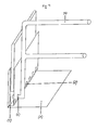
- FIG. 1 shows a product slide plate and a separating bracket
- FIG. 2 shows the product slide plate and the separating bracket on an existing shelf rack
- FIG. 3 shows the separating bracket
- FIG. 4 shows a first view of a front side of the product slide plate and the separating bracket
- FIG. 5 shows a rear side of the product slide plate and the separating bracket
- FIG. 6 shows a second view of a front side of the product slide plate and the separating bracket.
- the present invention overcomes the above-described problems.
- the invention as a retrofitting system, makes it possible for the advantages of EP 1455620 to be retrofitted into existing systems, irrespective of their configuration.
- the configuration of the product slide plate ( 1 ) according to an embodiment of the invention allows the product slide plate to be inserted into existing shelf racks ( FIG. 2 ).
- the product slide plate according to an embodiment of the invention entails the advantage that the design with the rectangular raised edges on the front ( 2 ) and on the rear ( 3 ) allows the separating bracket itself to be accommodated without the need for the separating bracket to be passed through downwards, as is the case with EP 1455620 ( FIG. 1 ).
- the separating bracket ( 4 ) according to an embodiment of the invention ( FIG. 3 ) has the advantage that, on one side, the insertion plate ( 5 ) is installed in such a way that it does not have to be inserted through the product slide plate downwards into the frame, but rather, said insertion plate ( 5 ) is merely inserted on one side into the rectangular cutouts ( 7 ) on the rear and the separating bracket is inserted on the front into the openings ( 8 ) which, depending on the design of the pin ( 6 ), correspond to said pin ( 6 ), so that, together with the product slide plate, it forms a uniform system that can be placed onto an existing frame for a shelf rack or onto an existing shelf rack.
- the design of the insertion plate ensures that, once it has been inserted, the separating bracket is laterally secured, preventing it from tilting away or tipping over, even when the compartments are filled only on one side.
- the configuration of the separating bracket with parallel cross bars has the advantage that, when the separating bracket is inserted into the product slide plate using one hand, it is pulled together on the cross bars, so that the distance between the insertion plate and the pin is reduced and the separating bracket is inserted into the openings under tension, likewise with one hand.
- the separating bracket according to an embodiment of the invention with the horizontal pin that is inserted only at a low height into the U-rail on the front raised edge of the product slide plate has the advantage that the U-rail can be configured on the front in such a way that enough space remains there to receive a product stop element at the removal end of the shelf rack ( FIGS. 4 , 5 ).
- the U-rail which is installed on the front raised edge of the product slide plate, enhances the stability and torsional stiffness of the product slide plate.
- the front raised edge is stabilized and reinforced by the U-rail itself, so that a raised product stop element can be inserted into the U-rail and can withstand the greater pressure exerted by the products.
Abstract
Description
Claims (2)
Applications Claiming Priority (4)
| Application Number | Priority Date | Filing Date | Title |
|---|---|---|---|
| EP10009164.4 | 2010-09-03 | ||
| EP10009164 | 2010-09-03 | ||
| EP10009164A EP2425742B1 (en) | 2010-09-03 | 2010-09-03 | Retrofitting system for shelf levels |
| PCT/EP2011/002588 WO2012028217A1 (en) | 2010-09-03 | 2011-05-25 | Retrofitting system for shelves |
Publications (2)
| Publication Number | Publication Date |
|---|---|
| US20130153524A1 US20130153524A1 (en) | 2013-06-20 |
| US8893903B2 true US8893903B2 (en) | 2014-11-25 |
Family
ID=43244865
Family Applications (1)
| Application Number | Title | Priority Date | Filing Date |
|---|---|---|---|
| US13/819,348 Expired - Fee Related US8893903B2 (en) | 2010-09-03 | 2011-05-25 | Retrofitting system for shelves |
Country Status (5)
| Country | Link |
|---|---|
| US (1) | US8893903B2 (en) |
| EP (1) | EP2425742B1 (en) |
| DK (1) | DK2425742T3 (en) |
| PL (1) | PL2425742T3 (en) |
| WO (1) | WO2012028217A1 (en) |
Cited By (7)
| Publication number | Priority date | Publication date | Assignee | Title |
|---|---|---|---|---|
| US20150198364A1 (en) * | 2014-01-15 | 2015-07-16 | Bsh Home Appliances Corporation | Refrigerated drawer and divider assembly therefor |
| US20150223620A1 (en) * | 2011-09-16 | 2015-08-13 | Rickard Nilsson | Product divider for shelf units |
| US10154739B2 (en) | 2013-12-02 | 2018-12-18 | Retail Space Solutions Llc | Universal merchandiser and methods relating to same |
| USD874197S1 (en) | 2014-12-01 | 2020-02-04 | Retail Space Solutions Llc | Shelf management dividers |
| US10555623B2 (en) * | 2018-01-03 | 2020-02-11 | Trion Industries, Inc. | Compact display tray |
| US10959540B2 (en) | 2016-12-05 | 2021-03-30 | Retail Space Solutions Llc | Shelf management system, components thereof, and related methods |
| US11045017B2 (en) | 2017-04-27 | 2021-06-29 | Retail Space Solutions Llc | Shelf-mounted tray and methods relating to same |
Families Citing this family (5)
| Publication number | Priority date | Publication date | Assignee | Title |
|---|---|---|---|---|
| DE102017110002A1 (en) * | 2017-05-09 | 2018-11-15 | Rickard Nilsson | Shelf unit for a shelving system and shelving system |
| BR112019026826A2 (en) * | 2017-06-16 | 2020-06-30 | Rtc Industries, Inc. | product display management system with railless boost mechanism |
| GB2566517A (en) * | 2017-09-15 | 2019-03-20 | Supply Point Systems Ltd | Shelving System |
| EP3498128B1 (en) | 2017-12-14 | 2020-01-08 | Bruegmann GmbH & Co. KG | System comprising goods support and dividers |
| US11304514B2 (en) * | 2020-03-25 | 2022-04-19 | John Stephen Lanphear | Shelving system with tilting shelves and adjustable dividers |
Citations (18)
| Publication number | Priority date | Publication date | Assignee | Title |
|---|---|---|---|---|
| US2529826A (en) * | 1947-02-15 | 1950-11-14 | Syndicate Glass Inc | Counter partition holder |
| US2589082A (en) * | 1949-02-17 | 1952-03-11 | Henry J Hickey | Counter bin construction |
| US2915193A (en) * | 1957-07-05 | 1959-12-01 | Malcolm C Bromberg | Display shelf construction |
| US3110402A (en) * | 1961-03-29 | 1963-11-12 | Cons Cigar Corp | Adjustable display rack |
| US3501020A (en) * | 1967-12-27 | 1970-03-17 | George Krikorian | Bin construction |
| US3512652A (en) * | 1968-05-20 | 1970-05-19 | Armstrong Store Fixture Corp | Banding and binning means for display shelves |
| US3698568A (en) * | 1970-12-18 | 1972-10-17 | Armstrong Store Fixture Corp | Partition structure with adjustable end member |
| US4346806A (en) * | 1980-03-11 | 1982-08-31 | Leggett & Platt, Incorporated | Shelf organizer |
| US5464105A (en) * | 1993-08-25 | 1995-11-07 | Deluxe Craft Manufacturing Co. | Multiple item shelving display system |
| US5464103A (en) * | 1993-08-09 | 1995-11-07 | Side-Kik Corporation | Display rack |
| DE19609432A1 (en) | 1996-03-11 | 1997-09-18 | Decor Metall Karl Becker Gmbh | Sales presentation display for refrigerated goods |
| US6116436A (en) * | 1998-09-18 | 2000-09-12 | Metro Industries, Inc. | Modular shelving storage system |
| US20030034319A1 (en) * | 2001-08-16 | 2003-02-20 | Meherin G. Scott | Apparatus for compartmentalizing a shelf |
| EP1455620A1 (en) | 2001-10-01 | 2004-09-15 | Rickard Nilsson | Shelf tier system for shelves and sliding racks |
| US20040256341A1 (en) * | 2003-06-17 | 2004-12-23 | Universal Display & Fixtures Company | Shelf having an adjustable divider |
| US20060096938A1 (en) * | 2004-11-08 | 2006-05-11 | Sanden Corporation | Shelf structure of showcase |
| US20060113262A1 (en) * | 2004-11-30 | 2006-06-01 | Knorring Edward I Jr | Shelf divider apparatus assisting in sliding sheet removal for gravity feed shelving |
| AU2008200144B1 (en) | 2008-01-10 | 2008-11-20 | Woolworths Limited | A divider for a display shelf |
-
2010
- 2010-09-03 EP EP10009164A patent/EP2425742B1/en not_active Not-in-force
- 2010-09-03 DK DK10009164.4T patent/DK2425742T3/en active
- 2010-09-03 PL PL10009164T patent/PL2425742T3/en unknown
-
2011
- 2011-05-25 WO PCT/EP2011/002588 patent/WO2012028217A1/en active Application Filing
- 2011-05-25 US US13/819,348 patent/US8893903B2/en not_active Expired - Fee Related
Patent Citations (18)
| Publication number | Priority date | Publication date | Assignee | Title |
|---|---|---|---|---|
| US2529826A (en) * | 1947-02-15 | 1950-11-14 | Syndicate Glass Inc | Counter partition holder |
| US2589082A (en) * | 1949-02-17 | 1952-03-11 | Henry J Hickey | Counter bin construction |
| US2915193A (en) * | 1957-07-05 | 1959-12-01 | Malcolm C Bromberg | Display shelf construction |
| US3110402A (en) * | 1961-03-29 | 1963-11-12 | Cons Cigar Corp | Adjustable display rack |
| US3501020A (en) * | 1967-12-27 | 1970-03-17 | George Krikorian | Bin construction |
| US3512652A (en) * | 1968-05-20 | 1970-05-19 | Armstrong Store Fixture Corp | Banding and binning means for display shelves |
| US3698568A (en) * | 1970-12-18 | 1972-10-17 | Armstrong Store Fixture Corp | Partition structure with adjustable end member |
| US4346806A (en) * | 1980-03-11 | 1982-08-31 | Leggett & Platt, Incorporated | Shelf organizer |
| US5464103A (en) * | 1993-08-09 | 1995-11-07 | Side-Kik Corporation | Display rack |
| US5464105A (en) * | 1993-08-25 | 1995-11-07 | Deluxe Craft Manufacturing Co. | Multiple item shelving display system |
| DE19609432A1 (en) | 1996-03-11 | 1997-09-18 | Decor Metall Karl Becker Gmbh | Sales presentation display for refrigerated goods |
| US6116436A (en) * | 1998-09-18 | 2000-09-12 | Metro Industries, Inc. | Modular shelving storage system |
| US20030034319A1 (en) * | 2001-08-16 | 2003-02-20 | Meherin G. Scott | Apparatus for compartmentalizing a shelf |
| EP1455620A1 (en) | 2001-10-01 | 2004-09-15 | Rickard Nilsson | Shelf tier system for shelves and sliding racks |
| US20040256341A1 (en) * | 2003-06-17 | 2004-12-23 | Universal Display & Fixtures Company | Shelf having an adjustable divider |
| US20060096938A1 (en) * | 2004-11-08 | 2006-05-11 | Sanden Corporation | Shelf structure of showcase |
| US20060113262A1 (en) * | 2004-11-30 | 2006-06-01 | Knorring Edward I Jr | Shelf divider apparatus assisting in sliding sheet removal for gravity feed shelving |
| AU2008200144B1 (en) | 2008-01-10 | 2008-11-20 | Woolworths Limited | A divider for a display shelf |
Non-Patent Citations (1)
| Title |
|---|
| European Patent Office, International Search Report in International Patent Application No. PCT/EP2011/002588 (Sep. 8, 2011). |
Cited By (9)
| Publication number | Priority date | Publication date | Assignee | Title |
|---|---|---|---|---|
| US20150223620A1 (en) * | 2011-09-16 | 2015-08-13 | Rickard Nilsson | Product divider for shelf units |
| US9392887B2 (en) * | 2011-09-16 | 2016-07-19 | Rickard Nilsson | Product divider for shelf units |
| US10154739B2 (en) | 2013-12-02 | 2018-12-18 | Retail Space Solutions Llc | Universal merchandiser and methods relating to same |
| US20150198364A1 (en) * | 2014-01-15 | 2015-07-16 | Bsh Home Appliances Corporation | Refrigerated drawer and divider assembly therefor |
| US9347704B2 (en) * | 2014-01-15 | 2016-05-24 | Bsh Home Appliances Corporation | Refrigerated drawer and divider assembly therefor |
| USD874197S1 (en) | 2014-12-01 | 2020-02-04 | Retail Space Solutions Llc | Shelf management dividers |
| US10959540B2 (en) | 2016-12-05 | 2021-03-30 | Retail Space Solutions Llc | Shelf management system, components thereof, and related methods |
| US11045017B2 (en) | 2017-04-27 | 2021-06-29 | Retail Space Solutions Llc | Shelf-mounted tray and methods relating to same |
| US10555623B2 (en) * | 2018-01-03 | 2020-02-11 | Trion Industries, Inc. | Compact display tray |
Also Published As
| Publication number | Publication date |
|---|---|
| EP2425742B1 (en) | 2012-11-07 |
| WO2012028217A1 (en) | 2012-03-08 |
| EP2425742A1 (en) | 2012-03-07 |
| DK2425742T3 (en) | 2013-03-11 |
| PL2425742T3 (en) | 2013-04-30 |
| US20130153524A1 (en) | 2013-06-20 |
Similar Documents
| Publication | Publication Date | Title |
|---|---|---|
| US8893903B2 (en) | Retrofitting system for shelves | |
| CA2684840C (en) | Product display with expandable front barrier | |
| CN103945734B (en) | Wall mounting memory structure | |
| US6491173B1 (en) | Wire basket system | |
| US20070221597A1 (en) | Supporting bracket for wall-mount rack | |
| US7021730B2 (en) | Drawer bracket | |
| US20080011696A1 (en) | Merchandising and product display system | |
| US20100078398A1 (en) | Product Management Display System | |
| US8251233B1 (en) | Shelving systems | |
| US10058173B2 (en) | Shelving assembly and method of assembly | |
| US20060163181A1 (en) | Clip for supporting wine bottles or the like | |
| WO2008115769A2 (en) | Product management display system with retaining wall | |
| US11540628B2 (en) | Merchandise display | |
| US20170086578A1 (en) | Shelf bracket | |
| US20130186847A1 (en) | Shelving Systems | |
| US20060091768A1 (en) | Adjustable door-mounted rack | |
| US9603468B2 (en) | Holding device for a bracket in a storage system | |
| US20050247654A1 (en) | Display system | |
| CA2857130A1 (en) | Double end frame | |
| RU2557723C2 (en) | Drawer with separation system | |
| US20160286983A1 (en) | Feed device for the automatic shifting of objects by means of a guide element, construction set, and method for mounting a feed device | |
| KR20130077850A (en) | A booktruck with bookends | |
| CN210643434U (en) | Shelf assembly and storage cabinet | |
| CA2633605A1 (en) | Container with removable divider panels | |
| JP5897586B2 (en) | Transport rail for drawer base |
Legal Events
| Date | Code | Title | Description |
|---|---|---|---|
| STCF | Information on status: patent grant |
Free format text: PATENTED CASE |
|
| FEPP | Fee payment procedure |
Free format text: PAYOR NUMBER ASSIGNED (ORIGINAL EVENT CODE: ASPN); ENTITY STATUS OF PATENT OWNER: SMALL ENTITY |
|
| MAFP | Maintenance fee payment |
Free format text: PAYMENT OF MAINTENANCE FEE, 4TH YR, SMALL ENTITY (ORIGINAL EVENT CODE: M2551) Year of fee payment: 4 |
|
| FEPP | Fee payment procedure |
Free format text: MAINTENANCE FEE REMINDER MAILED (ORIGINAL EVENT CODE: REM.); ENTITY STATUS OF PATENT OWNER: SMALL ENTITY |
|
| LAPS | Lapse for failure to pay maintenance fees |
Free format text: PATENT EXPIRED FOR FAILURE TO PAY MAINTENANCE FEES (ORIGINAL EVENT CODE: EXP.); ENTITY STATUS OF PATENT OWNER: SMALL ENTITY |
|
| STCH | Information on status: patent discontinuation |
Free format text: PATENT EXPIRED DUE TO NONPAYMENT OF MAINTENANCE FEES UNDER 37 CFR 1.362 |
|
| FP | Lapsed due to failure to pay maintenance fee |
Effective date: 20221125 |