US8881461B2 - Sash window restrictor - Google Patents
Sash window restrictor Download PDFInfo
- Publication number
- US8881461B2 US8881461B2 US12/999,751 US99975109A US8881461B2 US 8881461 B2 US8881461 B2 US 8881461B2 US 99975109 A US99975109 A US 99975109A US 8881461 B2 US8881461 B2 US 8881461B2
- Authority
- US
- United States
- Prior art keywords
- tab
- restrictor
- housing
- recited
- pivot position
- Prior art date
- Legal status (The legal status is an assumption and is not a legal conclusion. Google has not performed a legal analysis and makes no representation as to the accuracy of the status listed.)
- Expired - Fee Related, expires
Links
Images


Classifications
-
- E—FIXED CONSTRUCTIONS
- E05—LOCKS; KEYS; WINDOW OR DOOR FITTINGS; SAFES
- E05B—LOCKS; ACCESSORIES THEREFOR; HANDCUFFS
- E05B43/00—Time locks
-
- E—FIXED CONSTRUCTIONS
- E05—LOCKS; KEYS; WINDOW OR DOOR FITTINGS; SAFES
- E05C—BOLTS OR FASTENING DEVICES FOR WINGS, SPECIALLY FOR DOORS OR WINDOWS
- E05C3/00—Fastening devices with bolts moving pivotally or rotatively
- E05C3/12—Fastening devices with bolts moving pivotally or rotatively with latching action
-
- E—FIXED CONSTRUCTIONS
- E05—LOCKS; KEYS; WINDOW OR DOOR FITTINGS; SAFES
- E05B—LOCKS; ACCESSORIES THEREFOR; HANDCUFFS
- E05B63/00—Locks or fastenings with special structural characteristics
- E05B63/18—Locks or fastenings with special structural characteristics with arrangements independent of the locking mechanism for retaining the bolt or latch in the retracted position
- E05B63/20—Locks or fastenings with special structural characteristics with arrangements independent of the locking mechanism for retaining the bolt or latch in the retracted position released automatically when the wing is closed
-
- E—FIXED CONSTRUCTIONS
- E05—LOCKS; KEYS; WINDOW OR DOOR FITTINGS; SAFES
- E05B—LOCKS; ACCESSORIES THEREFOR; HANDCUFFS
- E05B65/00—Locks or fastenings for special use
- E05B65/08—Locks or fastenings for special use for sliding wings
- E05B65/0835—Locks or fastenings for special use for sliding wings the bolts pivoting about an axis parallel to the wings
- E05B65/0852—Locks or fastenings for special use for sliding wings the bolts pivoting about an axis parallel to the wings with a bolt under compression force
-
- E—FIXED CONSTRUCTIONS
- E05—LOCKS; KEYS; WINDOW OR DOOR FITTINGS; SAFES
- E05B—LOCKS; ACCESSORIES THEREFOR; HANDCUFFS
- E05B65/00—Locks or fastenings for special use
- E05B65/08—Locks or fastenings for special use for sliding wings
- E05B65/0864—Locks or fastenings for special use for sliding wings the bolts sliding perpendicular to the wings
-
- E—FIXED CONSTRUCTIONS
- E05—LOCKS; KEYS; WINDOW OR DOOR FITTINGS; SAFES
- E05C—BOLTS OR FASTENING DEVICES FOR WINGS, SPECIALLY FOR DOORS OR WINDOWS
- E05C1/00—Fastening devices with bolts moving rectilinearly
- E05C1/08—Fastening devices with bolts moving rectilinearly with latching action
- E05C1/10—Fastening devices with bolts moving rectilinearly with latching action with operating handle or equivalent member rigid with the latch
-
- E—FIXED CONSTRUCTIONS
- E05—LOCKS; KEYS; WINDOW OR DOOR FITTINGS; SAFES
- E05C—BOLTS OR FASTENING DEVICES FOR WINGS, SPECIALLY FOR DOORS OR WINDOWS
- E05C17/00—Devices for holding wings open; Devices for limiting opening of wings or for holding wings open by a movable member extending between frame and wing; Braking devices, stops or buffers, combined therewith
- E05C17/02—Devices for holding wings open; Devices for limiting opening of wings or for holding wings open by a movable member extending between frame and wing; Braking devices, stops or buffers, combined therewith by mechanical means
- E05C17/46—Devices for holding wings open; Devices for limiting opening of wings or for holding wings open by a movable member extending between frame and wing; Braking devices, stops or buffers, combined therewith by mechanical means in which the wing or a member fixed thereon is engaged by a movable fastening member in a fixed position; in which a movable fastening member mounted on the wing engages a stationary member
- E05C17/48—Devices for holding wings open; Devices for limiting opening of wings or for holding wings open by a movable member extending between frame and wing; Braking devices, stops or buffers, combined therewith by mechanical means in which the wing or a member fixed thereon is engaged by a movable fastening member in a fixed position; in which a movable fastening member mounted on the wing engages a stationary member comprising a sliding securing member
-
- E—FIXED CONSTRUCTIONS
- E05—LOCKS; KEYS; WINDOW OR DOOR FITTINGS; SAFES
- E05C—BOLTS OR FASTENING DEVICES FOR WINGS, SPECIALLY FOR DOORS OR WINDOWS
- E05C17/00—Devices for holding wings open; Devices for limiting opening of wings or for holding wings open by a movable member extending between frame and wing; Braking devices, stops or buffers, combined therewith
- E05C17/02—Devices for holding wings open; Devices for limiting opening of wings or for holding wings open by a movable member extending between frame and wing; Braking devices, stops or buffers, combined therewith by mechanical means
- E05C17/46—Devices for holding wings open; Devices for limiting opening of wings or for holding wings open by a movable member extending between frame and wing; Braking devices, stops or buffers, combined therewith by mechanical means in which the wing or a member fixed thereon is engaged by a movable fastening member in a fixed position; in which a movable fastening member mounted on the wing engages a stationary member
- E05C17/50—Devices for holding wings open; Devices for limiting opening of wings or for holding wings open by a movable member extending between frame and wing; Braking devices, stops or buffers, combined therewith by mechanical means in which the wing or a member fixed thereon is engaged by a movable fastening member in a fixed position; in which a movable fastening member mounted on the wing engages a stationary member comprising a single pivoted securing member
-
- E—FIXED CONSTRUCTIONS
- E05—LOCKS; KEYS; WINDOW OR DOOR FITTINGS; SAFES
- E05C—BOLTS OR FASTENING DEVICES FOR WINGS, SPECIALLY FOR DOORS OR WINDOWS
- E05C7/00—Fastening devices specially adapted for two wings
- E05C7/005—Fastening devices specially adapted for two wings for "Dutch doors", i.e. upper and lower wings
-
- E—FIXED CONSTRUCTIONS
- E05—LOCKS; KEYS; WINDOW OR DOOR FITTINGS; SAFES
- E05B—LOCKS; ACCESSORIES THEREFOR; HANDCUFFS
- E05B15/00—Other details of locks; Parts for engagement by bolts of fastening devices
- E05B15/0046—Ratchet mechanisms
-
- E—FIXED CONSTRUCTIONS
- E05—LOCKS; KEYS; WINDOW OR DOOR FITTINGS; SAFES
- E05B—LOCKS; ACCESSORIES THEREFOR; HANDCUFFS
- E05B15/00—Other details of locks; Parts for engagement by bolts of fastening devices
- E05B15/0093—Weight arrangements in locks; gravity activated lock parts
-
- E—FIXED CONSTRUCTIONS
- E05—LOCKS; KEYS; WINDOW OR DOOR FITTINGS; SAFES
- E05B—LOCKS; ACCESSORIES THEREFOR; HANDCUFFS
- E05B17/00—Accessories in connection with locks
- E05B17/0041—Damping means
-
- E—FIXED CONSTRUCTIONS
- E05—LOCKS; KEYS; WINDOW OR DOOR FITTINGS; SAFES
- E05C—BOLTS OR FASTENING DEVICES FOR WINGS, SPECIALLY FOR DOORS OR WINDOWS
- E05C19/00—Other devices specially designed for securing wings, e.g. with suction cups
- E05C19/02—Automatic catches, i.e. released by pull or pressure on the wing
- E05C19/022—Released by pushing in the closing direction
-
- E—FIXED CONSTRUCTIONS
- E05—LOCKS; KEYS; WINDOW OR DOOR FITTINGS; SAFES
- E05C—BOLTS OR FASTENING DEVICES FOR WINGS, SPECIALLY FOR DOORS OR WINDOWS
- E05C19/00—Other devices specially designed for securing wings, e.g. with suction cups
- E05C19/06—Other devices specially designed for securing wings, e.g. with suction cups in which the securing part if formed or carried by a spring and moves only by distortion of the spring, e.g. snaps
-
- E—FIXED CONSTRUCTIONS
- E05—LOCKS; KEYS; WINDOW OR DOOR FITTINGS; SAFES
- E05C—BOLTS OR FASTENING DEVICES FOR WINGS, SPECIALLY FOR DOORS OR WINDOWS
- E05C7/00—Fastening devices specially adapted for two wings
- E05C2007/007—Fastening devices specially adapted for two wings for a double-wing sliding door or window, i.e. where both wings are slidable
-
- Y—GENERAL TAGGING OF NEW TECHNOLOGICAL DEVELOPMENTS; GENERAL TAGGING OF CROSS-SECTIONAL TECHNOLOGIES SPANNING OVER SEVERAL SECTIONS OF THE IPC; TECHNICAL SUBJECTS COVERED BY FORMER USPC CROSS-REFERENCE ART COLLECTIONS [XRACs] AND DIGESTS
- Y10—TECHNICAL SUBJECTS COVERED BY FORMER USPC
- Y10T—TECHNICAL SUBJECTS COVERED BY FORMER US CLASSIFICATION
- Y10T292/00—Closure fasteners
- Y10T292/08—Bolts
- Y10T292/096—Sliding
- Y10T292/1014—Operating means
-
- Y—GENERAL TAGGING OF NEW TECHNOLOGICAL DEVELOPMENTS; GENERAL TAGGING OF CROSS-SECTIONAL TECHNOLOGIES SPANNING OVER SEVERAL SECTIONS OF THE IPC; TECHNICAL SUBJECTS COVERED BY FORMER USPC CROSS-REFERENCE ART COLLECTIONS [XRACs] AND DIGESTS
- Y10—TECHNICAL SUBJECTS COVERED BY FORMER USPC
- Y10T—TECHNICAL SUBJECTS COVERED BY FORMER US CLASSIFICATION
- Y10T292/00—Closure fasteners
- Y10T292/08—Bolts
- Y10T292/1043—Swinging
- Y10T292/1051—Spring projected
- Y10T292/1052—Operating means
-
- Y—GENERAL TAGGING OF NEW TECHNOLOGICAL DEVELOPMENTS; GENERAL TAGGING OF CROSS-SECTIONAL TECHNOLOGIES SPANNING OVER SEVERAL SECTIONS OF THE IPC; TECHNICAL SUBJECTS COVERED BY FORMER USPC CROSS-REFERENCE ART COLLECTIONS [XRACs] AND DIGESTS
- Y10—TECHNICAL SUBJECTS COVERED BY FORMER USPC
- Y10T—TECHNICAL SUBJECTS COVERED BY FORMER US CLASSIFICATION
- Y10T292/00—Closure fasteners
- Y10T292/08—Bolts
- Y10T292/1043—Swinging
- Y10T292/1075—Operating means
-
- Y—GENERAL TAGGING OF NEW TECHNOLOGICAL DEVELOPMENTS; GENERAL TAGGING OF CROSS-SECTIONAL TECHNOLOGIES SPANNING OVER SEVERAL SECTIONS OF THE IPC; TECHNICAL SUBJECTS COVERED BY FORMER USPC CROSS-REFERENCE ART COLLECTIONS [XRACs] AND DIGESTS
- Y10—TECHNICAL SUBJECTS COVERED BY FORMER USPC
- Y10T—TECHNICAL SUBJECTS COVERED BY FORMER US CLASSIFICATION
- Y10T292/00—Closure fasteners
- Y10T292/65—Braces
Definitions
- This invention relates to a device for limiting or restricting the extent of opening of a sliding sash window.
- This device will be referred to herein as a sash window restrictor.
- a sash restrictor comprising a housing, a tab which is retractable into the housing and extendable from the housing, and a mechanism acting between the tab and the housing which allows the tab to be pressed into the housing and which holds the tab in the housing, the mechanism comprising latching means to latch the tab in a retracted position.
- the latching means requires an actuation in order to release the tab and to allow the tab to extend from the housing.
- the latching means may comprise magnetic means.
- the tab comprises a first magnetic member and the housing comprises a second magnetic member and wherein, in the latched condition, the first magnetic member engages with the second magnetic member.
- the first magnetic member is relatively moved to a position sufficiently spaced from the second magnetic member.
- the first magnetic member is arranged, in use, to be moved relative to the second magnetic member manually by a user.
- the mechanism may comprise urging means to urge first magnetic member away from the second magnetic member.
- the mechanism may comprise urging means to urge the tab from the retracted position to the extended position.
- the urging means resists movement of the tab from the extended position to the retracted position.
- the urging means may comprise resilient means.
- the urging means may comprise a spring and preferably comprises a torsion spring.
- the tab is pivotally mounted to the housing.
- the tab comprises a first arm and a second arm.
- the first arm may comprise a latching member and the second arm may comprise an actuation member in order to unlatch the tab from a retracted position.
- the first arm may comprise an actuation member in order to latch the tab in a retracted position.
- a user manually moves the tab to a latched position to enable a sash to move relatively over the housing and the tab may then be unlatched either manually by the user or by the action of the sash in order to enable urging means to move the tab from the retracted position towards an extended position.
- the tab is movable to a first position in which the tab is at least partially (and more preferably totally) retracted into the housing and the tab may not project beyond the housing.
- the housing is movable to a second position in which at least a part of the tab projects outwardly relative to the housing.
- the tab is arranged to be manually moved from the second position to the first position and preferably for the tab to be latched in the first position.
- the tab is arranged to automatically move by movement means from the first position to the second position and preferably once the tab has been unlatched by an actuation.
- the tab is arranged to automatically move by movement means from a first retracted position to a second extended position once the tab has been unlatched by an actuation.
- the actuation may comprise a manual actuation and may comprise a push movement by a user.
- the actuation may comprise a contact force generated by movement of the sash window relative to the sash window restrictor.
- the tab may be retained in the housing by magnetic means.
- the housing will preferably be set into a vertical frame member of one sash (normally the upper, outer sash) of a window, at a position, say, 10 cm above the top rail of the lower sash when the windows are closed.
- the tab When the tab is retracted, the tab may lie substantially flush with the frame member, but when extended will project from the frame member sufficiently far to prevent the lower sash from passing. With the tab extended, the lower sash can be lifted until it reaches the tab but no further, so that a 10 cm gap will be opened at the bottom of the window.
- the tab When the window is to be opened fully, the tab will be pressed in and the bottom sash will be slid up, past the retracted tab, before the tab is able to extend.
- restrictor devices on both sides of the window, or just on one side. If there are restrictor devices on both sides, two separate operations will be required before the window can open, and this can provide an added security measure to make it more difficult for a window to be opened by a child.
- the device may have a second user-actuated feature so that the tab can only be pressed in once the second feature has been actuated. Again, this can provide an added security measure to make it more difficult for a window to be opened by a child.
- the tab may be pivoted in the housing such that one end of the tab will project from the housing, in the extended position. Alternatively, the tab may move linearly into and out of the housing.
- Part of the edge of the tab which, in use, will be facing the lower sash may have an inclined face to allow the sash to pass the tab, pushing it in to the housing as it does so, to allow the sash to pass even if the tab is not completely retracted.
- inclined face should only be at the outermost part of the tab edge, as the main part of that tab edge should be substantially at right angles to the direction of movement of the lower sash, so as to prevent the sash passing when the tab is fully extended.
- the mechanism between the tab and the housing preferably incorporates a spring and energy is stored in the spring when the tab is pushed into the housing.
- the mechanism may lock the tab in the retracted position, and a trigger may be activated by the passing of the lowers sash to release the lock and to allow the tab to be extended by the spring. While the lower sash lies in front of the device, the tab can only extend into contact with the lower sash frame, but one the lower sash is returned to its closed position, the tab will spring fully out to prevent reopening of the window without the tab being pushed in again.
- the tab can be linearly movable and can be controlled by a push-push mechanism where the first push locks the tab in its retracted position in the housing and a subsequent push releases the tab, allowing it to extend.
- the second push can be provided by the lower sash as it passes the device.
- the mechanism will not lock the tab in its retracted position, but will damp the restoring force of the spring, so that the spring is only able to slowly extend the tab.
- the tab may lock into the housing and a separate trigger can be operated, for example by movement of the lower sash, to release the tab.
- the stored spring force may be released only slowly, for example under the control of some form of damping system.
- the tab will start to extend as soon as the force pushing it into the retracted position is released.
- the speed at which the tab extends will be slow enough to allow the lower sash to be moved past the device before very much extension has taken place.
- an assembly comprising a sash and a sash restrictor, the sash restrictor comprising a housing, a tab which is retractable into the housing and extendable from the housing, and a mechanism acting between the tab and the housing which allows the tab to be pressed into the housing and which holds the tab in the housing, the mechanism comprising latching means to latch the tab in a retracted position.
- the sash restrictor prevents or at least inhibits movement of the sash relative to the sash restrictor whilst the tab is in the extended position.
- the sash restrictor enables movement of the sash passed the sash restrictor whilst the tab is initially in a retracted position.
- a kit for assembly into a sash restrictor comprising a housing, a tab which is retractable, in use, into the housing and extendable from the housing, and a mechanism acting, in use, between the tab and the housing which allows the tab to be pressed into the housing and which holds the tab in the housing, the mechanism comprising latching means to latch the tab in a retracted position.
- a method of restricting movement of a sash comprising mounting a sash restrictor adjacent to a sash wherein the sash restrictor comprises a housing, a tab which is retractable into the housing and extendable from the housing, and a mechanism acting between the tab and the housing which allows the tab to be pressed into the housing and which holds the tab in the housing, the mechanism comprising latching means to latch the tab in a retracted position.
- the method may comprise pushing the tab into the housing to latch the tab in a retracted position.
- the method may comprise pushing an actuating member to release the latching means.
- FIG. 1 is a side view through part of an upper and a lower sash, with a sash limiter device in accordance with the invention fitted in the upper sash;
- FIG. 2 is a schematic representation of the sash limiter device from FIG. 1 , with the tab extended;
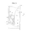
- FIG. 3 corresponds to FIG. 2 but shows the tab retracted
- FIG. 4 is a cross-sectional view through a second type of sash limiter device in accordance with the invention.
- FIG. 5 is a perspective view of the device of FIG. 4 ;
- FIG. 6 is an exploded view of a preferred embodiment of a sash window restrictor
- FIG. 7 is a side cross section of a preferred embodiment of a sash window restrictor
- FIG. 8 is a front view of a preferred embodiment of a sash window restrictor
- FIG. 9 is a perspective view of a preferred embodiment of a sash window restrictor
- FIG. 10 is a perspective view of a preferred embodiment of a sash window restrictor mounted to a sash window assembly
- FIG. 11 is a perspective view of another embodiment of a sash window restrictor mounted to a sash window assembly.
- FIG. 12 is an exploded view of another embodiment of a sash window restrictor
- FIG. 13 is an exploded view of another embodiment of a sash window restrictor
- FIG. 14 is a front perspective view of another embodiment of a sash window restrictor
- FIG. 15 is a rear perspective view of another embodiment of a sash window restrictor
- FIG. 16 is a bottom view of another embodiment of a sash window restrictor
- FIG. 17 is an exploded view of another embodiment of a sash window restrictor
- FIG. 18 is a front perspective view of the sash window restrictor of FIG. 17 ;
- FIG. 19 is a side view of the sash window restrictor of FIG. 17 ;
- FIG. 20 is a rear perspective view of another embodiment of a sash window restrictor
- FIG. 21 is an exploded view of another embodiment of a sash window restrictor
- FIG. 22 is a side view of the sash window restrictor of FIG. 21 ;
- FIG. 23 is a sectioned front view of the sash window restrictor of FIG. 21 ;
- FIG. 24 is a section through the sash window restrictor of FIG. 23 , along the line A-A;
- FIG. 25 is a perspective view of a push fit securement embodiment of a sash window restrictor
- FIG. 26 is a perspective view of an insert for mounting a sash window restrictor
- FIG. 27 is a sectional view of the insert of FIG. 26 ;
- FIG. 28 is a perspective view of a front mounted sash window restrictor according to another embodiment of the invention.
- FIG. 29 is a side view of the sash window restrictor of FIG. 28 ;
- FIG. 30 is a front view of the sash window restrictor of FIG. 28 ;
- FIG. 31 is a side view of the sash window restrictor of FIG. 28 ;
- FIG. 32 is a sectional view of the sash window restrictor of FIG. 30 along the line B-B;
- FIG. 33 is an exploded view of the sash window restrictor of FIG. 28 ;
- FIG. 34 is a front perspective view of a side mounted sash window restrictor according to another embodiment of the invention.
- FIG. 35 is an exploded view of a sash window restrictor according to another embodiment of the invention.
- FIG. 36 is a front perspective view of the sash window restrictor of FIG. 35 ;
- FIG. 37 is a side view of the sash window restrictor of FIG. 35 ;
- FIG. 38 is an exploded view of a sash window restrictor according to another embodiment of the invention.
- FIG. 39 is a rear perspective view of the sash window restrictor of FIG. 38 ;
- FIG. 40 is a cross-sectional view of the sash window restrictor of FIG. 38 ;
- FIG. 41 is a front perspective view of the sash window restrictor of FIG. 38 ;
- FIG. 42 shows the sash window restrictor of FIG. 38 mounted on a window frame
- FIG. 43 shows the sash window restrictor of FIG. 42 with the tab retracted
- FIG. 44 shows the sash window restrictor of FIG. 42 with the tab extended.
- FIG. 1 shows, in side view, an upper sash 10 and a lower sash 12 .
- the sashes are shown in the position which they would take up when the window is closed, and in this position, the horizontal meeting rails of the two sashes overlap at 14 .
- Weather seals 16 , 18 are shown on the respective sashes to provide a seal when the window is closed.
- the upper sash includes a sash limiter device at 20 .
- This device has a housing 22 which is recessed into the sash frame 10 , and a tab 24 which is movable between an extended, projecting position as shown, and a retracted position where it is housed substantially completely in the housing 22 .
- the lower sash 12 In the extended position of the tab 24 as shown in FIG. 1 , the lower sash 12 can be raised relative to the upper sash 10 , until the upper face of the lower sash comes into contact with the tab 24 . Further lifting of the lower sash 12 is then prevented. However when it is desired to open the window completely, and to raise the lower sash 12 past the limiter device 20 , the tab 24 can be pressed back and retracted into the housing 22 to allow the lower sash to pass the device.
- the retracted tab should automatically extend itself out of the housing 20 , once the leading edge of the lower sash 12 has moved passed.
- the tab will extend, either gradually or quickly, and as the lower sash is lifted further, the tab will bear against a surface of the lower sash frame. In this way, once the lower sash is lowered again and the window is closed, the tab will automatically move to its extended position without any user intervention being required.
- the tab will preferably be spring-loaded and can be pressed into the housing against spring pressure, with the spring being released to re-extend the tab once the lower sash has passed the device.
- a secondary lock may lock the tab in the open position, and require release before the tab can be pressed in. It may be necessary to hold a button or the like release mechanism whilst at the same time pressing in the tab.
- the tab itself may take up a number of different configurations.
- the tab is generally triangular and is pivoted at 26 in the housing.
- the tab may however slide in the housing between its extended and retracted positions.
- the tab has a tapered edge at 24 a , so that the lower sash can pass over the tab, even though the tab might not be fully retracted.
- FIG. 2 shows one example of a mechanism which can be used to control extension and retraction of the tab 24 .
- the extension of the tab, into the position shown in FIG. 2 is limited by engagement between an ear 28 on the tab and a shoulder 30 in the housing.
- a rack 32 which is integral with the tab engages with a first, inner sprocket 34 and rotates that sprocket in a clockwise direction. This rotation entrains an outer sprocket 36 .
- the outer sprocket 36 engages with a second sprocket 38 , and this second sprocket includes a coil spring 39 which is wound up as the tab is pushed in and the second sprocket rotates.
- a third sprocket 40 meshes with the sprocket 38 and has a release cam 42 at one point around its circumference, and an escapement 44 .
- the housing also contains a retaining plate 46 which is vertically slidable in the housing under the influence of a spring 48 .
- the first sprocket 34 has a clutch mechanism within the outer sprocket 36 , and this ensures that rotation of the sprocket 34 in a clockwise direction rotates the outer sprocket 36 , but when the inner sprocket rotates in the opposite direction, the sprocket 36 is not entrained. In the retracted position shown in FIG. 3 , the inner sprocket 34 can rotate freely within a part circular cut-out 52 in the tab.
- FIGS. 4 and 5 show another embodiment where the tab 124 slides linearly into and out of a housing 122 .
- the mechanism of this device works on a “push-push” principle, i.e. when the tab 124 is pushed in, it locks into a retracted position and if it is pushed again, the lock is released and a spring 139 extends the tab.
- the tab 124 has a tapered end, and the dimensions and stroke of the tab 124 will be such that, in the retracted position, the tip of the tab extends from the housing 122 , with the tapered face facing the direction from which the lower sash will approach.
- the lower sash When the lower sash contacts the tapered face, it will press the tab inwards to allow the window to pass, but also at the same time the lower sash will provide the second “push” to activate the release of the tab which will then be biased by the spring 139 against the face of the sash frame, as the sash moves past the tab.
- the tab 124 When the sash is moved back to its closed position, and passes the device 120 , the tab 124 will be free to move to its fully extended position where it blocks movement of the sash past the tab.
- the user To enable the window to be opened, the user must push the tab in so that it locks in the retracted position.
- the devices described are just two examples of sash window restrictors. It is important that the restrictor, once retracted to allow the window to be fully opened, automatically resets itself so that when the window is closed, the tab of the restrictor automatically moves into its window restricting position.
- the tab can be any shape which can prevent movement of one sash past the other, and the term “tab” is not intended to limit the possible forms of this component.
- sash restricting devices of this type on one side of a window, or on both sides of the window. If there are safety requirements requiring at least two manual operations before a window can be fully opened, these requirements can be met by fitting a device as described here on both sides of the window.
- the or each device can be provided with a secondary lock which locks the tab in the extended position and requires manual operation to release that lock before the tab can be pushed in.
- a preferred embodiment of a sash window restrictor 120 comprises a tab 124 which is pivotally mounted in a housing 122 .
- the tab provides a first arm 110 and a second arm 112 located on either side of the pivot member 114 .
- a torsion spring 116 is provided which urges the first arm from a first retracted position to a second extended position.
- the first arm 110 also includes a magnet 118 which is arranged in use to engage with a part of the housing 122 which thereby comprises a magnetic material.
- the housing may comprise a magnetic material or may have a specific magnetic element mounted therein.
- the sash window restrictor 120 is arranged in use to be mounted to a sash window assembly and is arranged to be mounted to a lower part (or lower frame member) of the upper sash and is mounted as an inset such that the housing plate 123 is substantially flush with the outer surface of the lower part (or frame member) of the upper sash, as shown in FIG. 10 .
- the sash window restrictor is arranged to be inset into the surface of timber or UPVC sashes.
- a user pushes the first arm 110 inwardly into the housing 122 in order for the magnet 118 to engage with the magnetic material of the housing 122 and for the tab 124 to be held in a retracted position.
- the lower sash window 130 can then be moved upwardly relative to the upper sash window 132 .
- the tab 124 is held in the retracted position, the second arm 112 of the tab 124 projects outwardly from the housing 122 such that an upper part 131 (or upper frame member) will contact the second arm 112 in order to unlatch the magnet 118 .
- the torsion spring 116 then urges the tab 124 to extend.
- a reinforcement plate 136 is mounted on an upper part of the lower sash window 130 in order to provide a reinforced contact area which is arranged to contact the tab 124 to prevent or inhibit the lower sash window from being opened.
- the sash window restrictor 120 is a surface mounted device which is arranged to be mounted to a side frame member 138 of an upper sash window 132 .
- the first arm 110 of the tab 124 normally projects out at an angle at the bottom of the sash window restrictor 120 and is held out by a torsion spring 116 which prevents the sash being raised beyond a chosen height.
- the first arm 110 on the sash window restrictor 120 is pressed fully in until it is held in by magnetic contact.
- the second arm 112 of the tab 124 now projects so that when the sash is raised it pushes the second arm 112 inwards breaking contact with the magnet and allowing the spring 116 to push the first arm 110 up to the face of the sash.
- the spring 116 pops the first arm 110 outwards and automatically resets it into the limiting position.
- the version which sits at the side of the sash has the arm running along the surface of the glass rather than the surface of the sash frame.
- the latching mechanism may be provided by any suitable releasable latching means.
- the latching means may comprise a plastic or metal snap feature to retain the first arm in the housing. Again the latching means is releasable by actuation as previously described.
- the sash window restrictor may be lockable such that a lock mechanism protects and restricts the use and operation of the sash window restrictor.
- the press button version will automatically be set in the locked position and will have to have the button pressed to free the locking arm allowing it to be depressed and the sash to be opened. When the sash is closed the locking button will reset preventing the arm from being manually depressed.
- the key version will have to be manually unlocked with the key before the limiter can be used in the normal way and then locked with the key to make it secure.
- the present invention is primarily applicable to sash windows and limiting or restricting the movement of a first sash window relative to a second sash window.
- the present invention can be used in other applications to prevent relative movement of a sash, for example the inset unit could be fitted into sliding patio doors to allow them to be opened a small distance while being secure.
- FIGS. 17 to 20 show an embodiment of a sash window restrictor of the present invention that is similar to the embodiment shown in FIGS. 113 to 16 .
- the sash window restrictor 220 of this embodiment includes an indicator 250 present in the second arm 212 of the tab 224 .
- the indicator 250 may take the form of a red coloured disc that is visible from a front side of the restrictor 220 .
- the indicator disc 250 is clearly visible by a user of the restrictor when the first arm 210 of the tab 224 is in an extended position thereby preventing upward movement of the sash.
- the indicator disc 250 comprises a retaining member 252 that sits in a recess 254 in the second arm 212 . So that the whole of the indicator disc 250 is visible to a user of the device 220 , a cut-out 256 is provided in a top edge 258 of the housing 222 . In this case the cut-out 258 is semi-circular.
- the latching means 360 used to hold the first arm 310 in a retracted position takes the form of a spring 360 that engages with a lower edge 364 of the first arm 310 of the tab 324 .
- the spring is a leaf spring 360
- the latching means may be any other form of spring or resilient member.
- the housing may be provided with a ball detent to retain the first arm 210 in a retracted position.
- the leaf spring 360 is held in position in the housing 322 by a small screw 362 .
- the spring 360 may be held using any suitable means such that one end of the spring 360 is immovably fixed to the housing 322 .
- the lower edge 364 of the first arm 310 rides over an upper end of the leaf spring 360 .
- the upper end of the leaf spring 360 is curved to provide a smooth engagement surface with the end 364 of the first arm 310 .
- the first arm 310 is held within the housing 322 such that the end 364 of the first arm 310 is behind the leaf spring 360 .
- the tab 324 pivots about the pivot member 314 and the first arm 310 is forced past the leaf spring 360 by the action of the torsion spring 316 .
- an indicator 350 is provided in a front face of the first arm 310 of the tab 324 .
- the indicator 350 has the same function as described hereinbefore.
- FIG. 25 shows a push fit embodiment of the present invention.
- This embodiment enables the sash window restrictor 420 to be quickly and easily secured in a frame member and, in particular, in a hollow upvc window frame member.
- the housing 422 includes two retaining members, in this example retaining arms 470 , one at each end 474 of the housing 422 .
- the arms 470 are resilient members and are connected to the housing 422 by a first section 472 of the arm 470 in such a way that this section 472 of the arm 470 forms a hinge 472 and the arms 470 lie parallel with the ends 474 of the housing 422 .
- the arms 470 are pressed towards the housing 422 causing the hinges 472 to bend.
- the energy stored in the hinge sections 472 of the arms 470 urges the arms 470 outwards once the restrictor is placed in the frame member holding the restrictor within the frame.
- the hole cut in the frame is such that as the restrictor 420 is pushed into the frame, the arms 470 are pressed in towards the housing 422 .
- the arms 470 are urged outwards by the action of the hinges 472 into the hollow of the frame thereby preventing the restrictor 420 from being pulled out.
- the arms 470 may include a projection 476 at the second end of the arm 470 . These projections 476 limit the distance the arms 470 can be pressed inwards which prevents the hinge 472 being bent too much.
- this insert 140 may be required to fix a restrictor 120 to a hollow upvc frame using screws.
- this insert 140 takes the form of a bar or plate having through-thickness cylindrical holes 142 . These cylindrical holes 142 align with the screw holes 144 present in the housing plate 123 and accommodate the shaft of the screw when the restrictor 120 is fixed in place. At least one face of the insert 140 may be shaped so that its profile is substantially the same as that of the upvc frame.
- any of the embodiments of a sash window restrictor described so far may include locking means which locks the tab in the extended position.
- these locking means are designed such that a manual operation, for example the pressed or sliding of a button, is required to release that lock before the tab can be pushed in.
- Such locking means provide a dual action requirement for each single sash window restrictor.
- the operation of the sash window restrictor may comprise a single action although as mentioned above the opening of the window may require a double action or dual action restricting mechanism.
- the sash window may be provided with two separate single action sash window restrictors.
- the sash window restrictor is provided with a dual action requirement.
- the sash window restrictor may be provided with a locking button that must be moved out of engagement with the tab to allow the tab to initially be pressed into the housing.
- the button is slid out of engagement with the tab to enable the tab to be pressed in which thereby provides a dual action requirement.
- the locking button is also arranged to automatically reset.
- FIGS. 28 to 33 show an embodiment of the present invention that is similar to the embodiment shown in FIGS. 6 to 9 .
- the restrictor 520 includes a slidable locking member 580 .
- the locking member 580 slides within a lock housing 582 fixed into the housing 522 of the restrictor 520 .
- the locking member is arranged to engage with the second arm 512 of the tab 524 .
- the locking member 580 is a substantially rectangular block having a locking foot 584 projecting at an angle from one end of the block. This locking foot 584 is designed to engage with a recess 586 in the second arm 512 of the tab 524 to hold the second arm 512 within the housing 522 and retain the first arm 510 in an extended position, as shown most clearly in FIG. 32 .
- biasing means in this case a compression spring 588 , is located between the locking member 580 and a part of the housing 522 .
- the compression spring 588 extends through the lock housing 582 , however, alternatively, the compression spring 588 may be located between the locking member 580 and a part of the lock housing 582 .
- the compression spring 588 acts to bias the locking member 580 towards the tab 524 , and in particular towards the second arm 512 of the tab 524 .
- the locking member 580 In order to retract the first arm 510 of the tab 524 and push the first arm 510 within the housing 522 , the locking member 580 must first be disengaged from the second arm 512 .
- the locking foot 584 is engaged in the recess 586 in the second arm 512 of the tab 524 and is held in this position by the action of the compression spring 588 .
- the locking member 580 must first be slid in a direction away from the tab 580 , in this example in an upwards direction into the lock housing 582 .
- the first arm 510 on the sash window restrictor 520 can then be pressed fully in until it is held in by magnetic contact, as described hereinbefore.
- the compression spring 588 urges the locking member 580 downwards so that the locking foot 584 extends behind the second arm 512 of the tab 524 .
- the second arm 512 of the tab 524 now projects outwards so that when the sash is raised it acts to push the second arm 512 inwards.
- a rear edge of the second arm 512 contacts a sloping face 590 of the locking member 580 and the locking member 580 slides upwards over the second arm 512 .
- the locking member 580 slides over the tip of the second arm 512 and the locking member 580 is then urged towards the second arm 512 and the locking foot 584 engages in the recess 586 .
- the magnet 518 located in the first arm 510 engages with a second magnet 592 that is fixed to the housing 522 .
- the two magnets 518 , 592 are oriented so that opposite poles of the magnets 518 , 592 make touching contact when the first arm 510 moves inside the housing 522 .
- a further embodiment shown in FIG. 34 is substantially the same as the embodiment shown in FIG. 33 but differs in the means for fixing the sash window restrictor to a frame.
- the sash window restrictor shown in FIG. 33 is front-mounted and fixed to a frame by means of the housing plate 523 , in particular by screws that pass through holes in the mounting plate 523 and into the frame of the window.
- the embodiment shown in FIG. 34 does not include fixing means in the housing plate 623 , and instead is fixed within a frame by screws or similar that pass through channels 694 in a rear part 696 of the housing 622 .
- FIGS. 35 to 37 illustrate an embodiment of a sash window restrictor 720 that is substantially similar to the embodiment shown in FIGS. 28 to 32 , however, in this case, the housing 722 is such that the restrictor 720 may be fitted to the outside of a window frame. This has the advantage that the restrictor may be easily retro-fit as it does not require the restrictor to be mounted within the frame of the window.
- FIGS. 38 to 44 A further embodiment of a sash window restrictor having a lock mechanism is shown in FIGS. 38 to 44 .
- the housing 822 is shaped so that the restrictor 820 may be fitted to an outer frame 133 of the window, with the first arm 810 of the tab 824 contacting an upper part 131 of a lower sash as illustrated in FIGS. 42 to 44 .
- a button 898 is attached to the second arm 812 .
- the button may be attached to the second arm 812 using any suitable means, but in this example it is fixed to the second arm 812 using a screw 899 .
- the button 898 is substantially cuboid, with the face opposing the second arm being curved 901 in one direction. The end of the curved surface 901 stands proud of a top face 903 of the button 898 thereby forming a lip 905 .
- the tab 824 is pivotally mounted in the housing 822 such that at least a part of the button 898 protrudes through the housing 822 and is visible from a front side 904 of the housing 822 . In this arrangement, the arms 810 , 812 of the tab 824 protrude from a rear side 906 of the housing 822 .
- the slide member 880 comprises a slide plate 905 and a mounting block 907 .
- the slide plate 905 and mounting block 907 are joined rigidly together such that a part of the slide plate 905 is on a front side 904 of the housing 822 , and the mounting block 907 is on the rear side 906 of the housing 882 .
- a lock housing 882 is fixed into the housing 822 , and the mounting block 907 slides within this lock housing 882 .
- Biasing means in this case a compression spring 888 , is located between the mounting block 907 and a part of the lock housing 882 .
- the compression spring 888 acts to bias the locking member 580 towards the tab 524 , and in particular towards the second arm 512 and the button 898 .
- the button can then be pressed through the housing. Pressing the button in this way causes the tab to rotate about the pivot member 814 so that the first arm 810 on the sash window restrictor 820 is retracted until it is held by magnetic contact, as described hereinbefore.
- the compression spring 888 urges the locking member 880 downwards so that the end of the slide plate extends partly in front of the button. In this position a chamfered edge 911 of the slide plate 905 rests against the curved surface 901 of the button 898 .
- the sash window restrictor may be mounted to any suitable part of the window or window frame including a window frame member, a sash member, a stile, a jamb etc.
- the assembly may include a bracket or abutment member which is arranged on the other part of the window assembly from the tab and provides a suitable placed abutment surface to abut with the tab to restrict the opening of the window.
- the present invention is for use with all suitable sash windows, for example horizontal and vertical sliding sash windows.
Abstract
Description
Claims (50)
Applications Claiming Priority (7)
| Application Number | Priority Date | Filing Date | Title |
|---|---|---|---|
| GB0811324.3 | 2008-06-19 | ||
| GB0811324A GB2461079A (en) | 2008-06-19 | 2008-06-19 | Sash window restrictor having a protruding member and retaining mechanism |
| GB0817136A GB2461107A (en) | 2008-06-19 | 2008-09-18 | Sash window restrictor having a protruding member and retaining mechanism |
| GB0817137A GB2461108A (en) | 2008-06-19 | 2008-09-18 | Sash window restrictor having a protruding member and retaining latch |
| GB0817136.5 | 2008-09-18 | ||
| GB0817137.3 | 2008-09-18 | ||
| PCT/GB2009/001526 WO2009153562A1 (en) | 2008-06-19 | 2009-06-19 | Sash window restrictor |
Related Parent Applications (1)
| Application Number | Title | Priority Date | Filing Date |
|---|---|---|---|
| PCT/GB2009/001526 A-371-Of-International WO2009153562A1 (en) | 2008-06-19 | 2009-06-19 | Sash window restrictor |
Related Child Applications (1)
| Application Number | Title | Priority Date | Filing Date |
|---|---|---|---|
| US14/499,858 Division US9816300B2 (en) | 2008-06-19 | 2014-09-29 | Sash window restrictor |
Publications (2)
| Publication Number | Publication Date |
|---|---|
| US20110113695A1 US20110113695A1 (en) | 2011-05-19 |
| US8881461B2 true US8881461B2 (en) | 2014-11-11 |
Family
ID=39682872
Family Applications (4)
| Application Number | Title | Priority Date | Filing Date |
|---|---|---|---|
| US12/999,751 Expired - Fee Related US8881461B2 (en) | 2008-06-19 | 2009-06-19 | Sash window restrictor |
| US14/499,858 Active US9816300B2 (en) | 2008-06-19 | 2014-09-29 | Sash window restrictor |
| US15/691,010 Active US11136797B2 (en) | 2008-06-19 | 2017-08-30 | Sash window restrictor |
| US17/464,777 Pending US20210404228A1 (en) | 2008-06-19 | 2021-09-02 | Sash window restrictor |
Family Applications After (3)
| Application Number | Title | Priority Date | Filing Date |
|---|---|---|---|
| US14/499,858 Active US9816300B2 (en) | 2008-06-19 | 2014-09-29 | Sash window restrictor |
| US15/691,010 Active US11136797B2 (en) | 2008-06-19 | 2017-08-30 | Sash window restrictor |
| US17/464,777 Pending US20210404228A1 (en) | 2008-06-19 | 2021-09-02 | Sash window restrictor |
Country Status (6)
| Country | Link |
|---|---|
| US (4) | US8881461B2 (en) |
| EP (1) | EP2367998B1 (en) |
| AU (1) | AU2009261737B2 (en) |
| CA (1) | CA2728416C (en) |
| GB (3) | GB2461079A (en) |
| WO (2) | WO2009153562A1 (en) |
Cited By (12)
| Publication number | Priority date | Publication date | Assignee | Title |
|---|---|---|---|---|
| US20150015000A1 (en) * | 2008-06-19 | 2015-01-15 | Mighton Products Limited | Sash window restrictor |
| US20170122008A1 (en) * | 2014-05-19 | 2017-05-04 | Hao Min | Safety locking mechanism for lockset |
| US20180209186A1 (en) * | 2017-01-20 | 2018-07-26 | Pella Corporation | Window opening control systems and methods |
| US10815707B2 (en) * | 2010-10-22 | 2020-10-27 | Amesbury Group, Inc. | Window opening limit devices and method of use |
| US20210025197A1 (en) * | 2018-03-23 | 2021-01-28 | Pella Corporation | Sliding door foot bolt |
| US11047157B1 (en) | 2006-03-28 | 2021-06-29 | Vision Industries Group, Inc. | Vent stop |
| US11118376B1 (en) | 2017-10-18 | 2021-09-14 | Vision Industries Group, Inc. | Combination sash lock and tilt latch and slidable window vent stop |
| US11156024B1 (en) * | 2019-11-12 | 2021-10-26 | Barry G. Lawrence | Window opening control device |
| US11168492B1 (en) | 2017-02-16 | 2021-11-09 | Vision Industries Group, Inc. | Tamper resistant sash lock |
| US11168495B1 (en) | 2018-08-01 | 2021-11-09 | Vision Industries Group, Inc. | Automatically resetting window vent stop with dual safety features |
| US11187010B1 (en) | 2019-09-19 | 2021-11-30 | Vision Industries, Inc. | Forced-entry-resistant sash lock |
| US20230110893A1 (en) * | 2021-10-08 | 2023-04-13 | Leonardo Stabile | Sliding sash assemblies |
Families Citing this family (28)
| Publication number | Priority date | Publication date | Assignee | Title |
|---|---|---|---|---|
| US8235430B2 (en) | 2006-03-28 | 2012-08-07 | Vision Industries, Inc. | Window vent stop with flexible side engagement pieces |
| US10107021B1 (en) | 2006-03-28 | 2018-10-23 | Vision Industries Group, Inc. | Window vent stop with plastic spring member for bi-directional biasing of the tumbler |
| US9840860B2 (en) | 2009-05-29 | 2017-12-12 | Vision Industries Group, Inc. | Double-action, adjustable, after-market sash stop |
| US8776440B2 (en) | 2010-12-17 | 2014-07-15 | Marvin Lumber And Cedar Company | Sash limiter apparatus and method |
| US8978304B2 (en) | 2012-04-30 | 2015-03-17 | Marvin Lumber And Cedar Company | Double hung latch and jamb hardware |
| US8806809B1 (en) * | 2013-03-14 | 2014-08-19 | Barry G. Lawrence | Window vent stop and method |
| US10704297B2 (en) | 2014-03-06 | 2020-07-07 | Vision Industries, Inc. | Impact resistant lock and tilt latch combination for a sliding sash window |
| US10865592B2 (en) | 2014-03-06 | 2020-12-15 | Vision Industries Group, Inc. | Sash lock and tilt latch also functioning as a window vent stop, with automatic locking upon closure |
| US10119310B2 (en) | 2014-03-06 | 2018-11-06 | Vision Industries Group, Inc. | Combination sash lock and tilt latch with improved interconnection for blind mating of the latch to the lock |
| US10844642B2 (en) | 2014-03-06 | 2020-11-24 | Vision Industries Group, Inc. | Combination four-position sash lock and tilt latch also functioning as a window opening control device |
| CA2886226C (en) | 2014-03-27 | 2017-08-15 | Daniel Jon Curtis | Window opening control device for horizontal and vertical sliding windows |
| DE102014213383A1 (en) * | 2014-07-09 | 2016-01-14 | Fidlock Gmbh | Manually operated closure device with delay device |
| US9936672B2 (en) * | 2014-07-22 | 2018-04-10 | Doskocil Manufacturing Company, Inc. | Latching mechanism for pet enclosure |
| WO2016028770A1 (en) * | 2014-08-18 | 2016-02-25 | HavenLock Inc. | Improved locking apparatus, locking member, and method of use |
| US11793769B2 (en) | 2014-08-25 | 2023-10-24 | Jai Shankar Sukul | Device with compositions for delivery to the lungs, the oral mucosa and the brain |
| US9975695B2 (en) * | 2015-06-03 | 2018-05-22 | Serio-Us Industries, Inc. | Locking device for front load container |
| JP6537409B2 (en) * | 2015-08-28 | 2019-07-03 | Ykk Ap株式会社 | Sliding door with lock device with opening support mechanism and lock device with opening support mechanism |
| US11365561B2 (en) | 2017-01-17 | 2022-06-21 | Marvin Lumber And Cedar Company, Llc | Fenestration assembly operation hardware and methods for same |
| CN106812397B (en) * | 2017-02-16 | 2018-06-01 | 王力安防科技股份有限公司 | A kind of dust-proof bolt with clearance compensation function |
| US10633897B2 (en) | 2017-02-16 | 2020-04-28 | Vision Industries Group, Inc. | Tamper-resistant lock |
| US10844636B2 (en) | 2017-05-23 | 2020-11-24 | Vision Industries Group, Inc. | Combination forced entry resistant sash lock and tilt latch, also functioning as a window opening control device |
| CA3011471C (en) | 2017-07-13 | 2021-10-26 | Marvin Lumber And Cedar Company, D/B/A Marvin Windows And Doors | Integrated fenestration status monitoring systems and methods for the same |
| CN107191080B (en) * | 2017-08-01 | 2018-09-21 | 石光明 | Stealthy door-inhale |
| CN110331905B (en) * | 2018-06-27 | 2020-10-23 | 义乌市绳墨新材料有限公司 | Anti-theft chain device |
| CN111173365B (en) * | 2018-11-13 | 2021-08-06 | 派阁国际(香港)有限公司 | Handle |
| USD916580S1 (en) * | 2019-04-30 | 2021-04-20 | Ningbo Fabe Child Safety Co., Ltd. | Door handle safety lock |
| CN110670966A (en) * | 2019-09-19 | 2020-01-10 | 安徽豆米科技有限公司 | Intelligent door lock based on internet |
| US11180942B1 (en) | 2019-11-15 | 2021-11-23 | Barry G. Lawrence | Removable window vent stop |
Citations (42)
| Publication number | Priority date | Publication date | Assignee | Title |
|---|---|---|---|---|
| US417868A (en) | 1889-12-24 | Sash-fastener | ||
| US756453A (en) | 1903-12-23 | 1904-04-05 | P & F Corbin | Sash-bolt. |
| US785367A (en) * | 1904-12-03 | 1905-03-21 | Rector T Mason | Window-sash fastener. |
| US833900A (en) | 1905-09-16 | 1906-10-23 | Isaac G Sigler | Sash check or lock. |
| US881658A (en) | 1906-09-01 | 1908-03-10 | John W Bowman | Sash-lock. |
| US976777A (en) | 1909-11-10 | 1910-11-22 | John F Peterson | Gravity sash-lock. |
| US1601051A (en) | 1922-08-22 | 1926-09-28 | Clark Alexander | Window lock |
| US1724637A (en) | 1927-08-31 | 1929-08-13 | Roy H Bergstrom | Sash latch |
| US4824154A (en) | 1988-02-10 | 1989-04-25 | Ashland Products Company | Security lock for double-hung window |
| US4917416A (en) | 1988-09-21 | 1990-04-17 | Certainteed Corporation | Window latching device |
| US4919464A (en) * | 1985-11-07 | 1990-04-24 | Richards Roger C | Magnetically operated latch |
| WO1991018168A1 (en) | 1990-05-14 | 1991-11-28 | Ciposa Microtechniques S.A. | Timed triggering control device for a mechanism |
| US5188405A (en) * | 1991-03-06 | 1993-02-23 | Rev-A-Shelf, Inc. | Locking device for a latch |
| US5248174A (en) | 1992-11-20 | 1993-09-28 | Ashland Products, Inc. | Security lock for sash window |
| US5536052A (en) | 1994-10-04 | 1996-07-16 | Ro-Mai Industries, Inc. | Sash lock with improved tumbler |
| US5553903A (en) | 1994-08-22 | 1996-09-10 | Ashland Products, Inc. | Window vent stop |
| US5575116A (en) | 1995-06-06 | 1996-11-19 | Certainteed Corporation | Window vent stop |
| US5806900A (en) | 1996-11-05 | 1998-09-15 | Ashland Products, Inc. | Stop for a slidable window |
| WO1999046464A2 (en) | 1998-03-09 | 1999-09-16 | Southco, Inc. | Latch |
| US6000735A (en) | 1998-11-06 | 1999-12-14 | Jormac Products, Inc. | Automatic child-resistant sliding door lock |
| US6021603A (en) | 1998-04-07 | 2000-02-08 | Ashland Products, Inc. | Tilt-latch with bolt stop |
| WO2004038141A1 (en) | 2002-10-24 | 2004-05-06 | Assa Abloy Financial Services Ab | A self-latching device |
| US6848728B2 (en) | 2003-04-01 | 2005-02-01 | Anthony Rotondi | Window fastener |
| GB2410058A (en) | 2004-01-15 | 2005-07-20 | Nifco Inc | Door latch with damped bolt return |
| WO2005078218A1 (en) | 2004-02-18 | 2005-08-25 | Assa Abloy New Zealand Limited | Self latching device |
| US7147255B2 (en) * | 2001-04-05 | 2006-12-12 | 420820 Ontario Limited | Combination cam lock/tilt latch and latching block therefor with added security feature |
| US20070209285A1 (en) | 2006-02-28 | 2007-09-13 | William Bestler | Positive action lock for sliding windows |
| US20070222233A1 (en) | 2006-03-24 | 2007-09-27 | Luke Liang | Night latch |
| US20070222234A1 (en) | 2006-03-24 | 2007-09-27 | Luke Liang | Button mechanism for a night latch for a sliding member |
| US20080079268A1 (en) | 2006-08-17 | 2008-04-03 | Luke Liang | Night latch |
| US20080127568A1 (en) | 2006-03-28 | 2008-06-05 | Luke Liang | Window vent stop with flexible side engagement pieces |
| US7396054B2 (en) | 2005-08-17 | 2008-07-08 | Christian Carrier | Sash locking device for casement window |
| US7431356B2 (en) | 2003-07-18 | 2008-10-07 | Vision Industries Group, Inc. | Window vent stop |
| US7441811B2 (en) | 2004-04-01 | 2008-10-28 | Lawrence Barry G | Casement window lock |
| US7452014B2 (en) | 2005-05-02 | 2008-11-18 | Truth Hardware Corporation | Multi-point sash lock system for casement window |
| US7494164B1 (en) | 2007-09-10 | 2009-02-24 | Jeld-Wen, Inc. | Window latch |
| US7530611B2 (en) | 2006-03-28 | 2009-05-12 | Vision Industry Group | Night latch for sliding member |
| WO2009072839A1 (en) | 2007-12-05 | 2009-06-11 | General Rotor Co., Ltd. | Locking device for a window |
| US20090206616A1 (en) | 2005-08-01 | 2009-08-20 | Luke Liang | Auto vent stop |
| US7588271B1 (en) | 2006-09-15 | 2009-09-15 | Lawrence Barry G | Window security lock |
| US7591494B2 (en) | 2005-12-19 | 2009-09-22 | Weather Shield Mfg., Inc. | Window lock assembly |
| JP5171848B2 (en) | 2007-02-22 | 2013-03-27 | イーストマン コダック カンパニー | Ex situ doped nanoparticle semiconductor transport layer |
Family Cites Families (48)
| Publication number | Priority date | Publication date | Assignee | Title |
|---|---|---|---|---|
| US226033A (en) | 1880-03-30 | Ohaeles m | ||
| US719981A (en) | 1901-07-18 | 1903-02-10 | Alexander William Adams | Automatic sash-lock. |
| US756439A (en) | 1902-03-01 | 1904-04-05 | Warren F Vrooman | Siphon-gaged liquid-measure. |
| US764493A (en) | 1903-11-10 | 1904-07-05 | Jonathan Noseworthy | Sash-lock. |
| US1261274A (en) * | 1917-09-05 | 1918-04-02 | Richard Newsam | Window-latch. |
| US2503370A (en) | 1946-07-03 | 1950-04-11 | Zanona John | Forget-proof window lock |
| JPH05171848A (en) * | 1991-12-10 | 1993-07-09 | Kitagawa Ind Co Ltd | Lock mechanism of sliding door |
| US5485733A (en) * | 1993-05-13 | 1996-01-23 | Hoffman; Charles G. | Concealed magnetic lock for cabinet closure |
| GB2286627B (en) | 1993-12-28 | 1997-04-16 | Total Prod Sales Ltd | Door latch lock |
| US6000753A (en) | 1996-12-05 | 1999-12-14 | Cosco, Inc. | Child car seat foundation |
| AU7144798A (en) | 1997-05-16 | 1998-12-08 | Bausch & Lomb Incorporated | Adjustable magnifying apparatus and method for viewing video or computer screens |
| USD420375S (en) | 1998-09-25 | 2000-02-08 | Bausch & Lomb Incorporated | Visor magnifier front |
| USD430887S (en) | 1999-10-08 | 2000-09-12 | Bausch & Lomb Incorporated | Visor magnifier |
| US6364375B1 (en) * | 2000-02-15 | 2002-04-02 | Ashland Products, Inc. | Apparatus for securing sash window |
| US6625827B1 (en) | 2000-03-03 | 2003-09-30 | Finger Lakes Intellectual Property Llc | Universal tension spring support member for bed rails or bed frame |
| US7610682B2 (en) | 2000-03-03 | 2009-11-03 | Finger Lakes Intellectual Property, Llc | Method of affixing a caster on a wooden or plastic furniture leg |
| US6568031B1 (en) | 2000-03-03 | 2003-05-27 | Finger Lakes Intellectual Property, Llc | Caster assembly for a bed frame member or furniture |
| US6826790B1 (en) | 2000-03-25 | 2004-12-07 | Finger Lakes Intellectual Property, Llc | Bed frame shields |
| US6418578B1 (en) | 2000-03-25 | 2002-07-16 | Finger Lakes Intellectual Property, Llc | Protective guard for furniture leg |
| US6356400B1 (en) | 2000-08-28 | 2002-03-12 | Bausch & Lomb Incorporated | Eyewear magnifying loupe |
| US6854214B2 (en) * | 2000-11-14 | 2005-02-15 | Ashland Products, Inc. | Stop for a slidable window |
| US6685379B2 (en) | 2001-06-11 | 2004-02-03 | Finger Lakes Intellectual Property Llc | Plug for keyhole slots |
| US20030097714A1 (en) | 2001-11-29 | 2003-05-29 | Polevoy Richard S. | Snap on protective members for bed frames |
| US7559588B2 (en) * | 2001-12-17 | 2009-07-14 | Liang Luke K | Window vent stop |
| CA2475874C (en) | 2002-02-11 | 2012-01-03 | Finger Lakes Intellectual Property Llc | Bed frame center beam locking mechanism |
| US6764176B1 (en) | 2003-03-20 | 2004-07-20 | Bausch & Lomb Incorporated | Eyewear magnifying loupe |
| US7296831B2 (en) | 2003-09-03 | 2007-11-20 | Paul Generowicz | Window lock keeper |
| US7007321B2 (en) | 2003-11-21 | 2006-03-07 | Finger Lakes Intellectual Property Llc | Side rail end connection system for bed frame |
| US7363664B2 (en) | 2004-05-14 | 2008-04-29 | Finger Lakes Intellectual Property, L.L.C. | T-shaped side rails for bed frame |
| US7219378B2 (en) | 2004-05-14 | 2007-05-22 | Finger Lakes Intellectual Property, Llc | Support member for a bed frame |
| US7363665B2 (en) | 2004-05-14 | 2008-04-29 | Finger Lakes Intellectual Property, Llc | Bed frame with extended bumper assembly |
| WO2006086762A2 (en) | 2005-02-11 | 2006-08-17 | Finger Lakes Intellectual Property, Llc | Slide lock for center beam of a bedframe |
| WO2006088869A2 (en) | 2005-02-15 | 2006-08-24 | Finger Lakes Intellectual Property, Llc | Foundation headboard bracket system for bed |
| WO2008057368A2 (en) | 2006-11-01 | 2008-05-15 | Finger Lakes Intellectual Property, Llc | Exercise device |
| US7954184B2 (en) | 2007-03-12 | 2011-06-07 | Finger Lakes Intellectual Property Llc | Structural members for bed frame |
| GB2461079A (en) * | 2008-06-19 | 2009-12-23 | Mighton Products Ltd | Sash window restrictor having a protruding member and retaining mechanism |
| US8832881B2 (en) | 2009-03-31 | 2014-09-16 | Finger Lakes Intellectual Property Llc | Bed frame having protective plastic casing |
| US20100300000A1 (en) * | 2009-05-29 | 2010-12-02 | Luke Liang | Single action vent stop |
| US8360484B2 (en) * | 2009-07-30 | 2013-01-29 | Vision Industries Group, Inc. | Vent stop for wooden and other windows |
| US20120291359A1 (en) * | 2010-01-18 | 2012-11-22 | John B, Higman and Valorie J. Higman; Trustees of the Higman Family Trust U/D/T as Amened AND | Recessable rotary sliding door handle |
| US8397546B2 (en) * | 2010-09-21 | 2013-03-19 | Cosco Management, Inc. | Cabinet security system |
| US8662347B2 (en) | 2010-09-29 | 2014-03-04 | Covidien Lp | Medical electrode dispensers |
| CA2755576A1 (en) * | 2010-10-22 | 2012-04-22 | Amesbury Group, Inc. | Window opening limit devices and method of use |
| US8776440B2 (en) * | 2010-12-17 | 2014-07-15 | Marvin Lumber And Cedar Company | Sash limiter apparatus and method |
| EP2690988B1 (en) | 2011-03-31 | 2018-03-07 | Finger Lakes Intellectual Property, LLC | Unitary t-shaped bed frame member |
| US9247825B2 (en) | 2011-10-14 | 2016-02-02 | Finger Lakes Intellectual Property Llc | Wrap around bed frame |
| US8776442B1 (en) * | 2012-11-06 | 2014-07-15 | Barry G. Lawrence | Window vent latch sheath and method |
| US8806809B1 (en) * | 2013-03-14 | 2014-08-19 | Barry G. Lawrence | Window vent stop and method |
-
2008
- 2008-06-19 GB GB0811324A patent/GB2461079A/en not_active Withdrawn
- 2008-09-18 GB GB0817136A patent/GB2461107A/en not_active Withdrawn
- 2008-09-18 GB GB0817137A patent/GB2461108A/en not_active Withdrawn
-
2009
- 2009-06-19 US US12/999,751 patent/US8881461B2/en not_active Expired - Fee Related
- 2009-06-19 WO PCT/GB2009/001526 patent/WO2009153562A1/en active Application Filing
- 2009-06-19 AU AU2009261737A patent/AU2009261737B2/en active Active
- 2009-06-19 EP EP09766123A patent/EP2367998B1/en active Active
- 2009-06-19 WO PCT/GB2009/001529 patent/WO2009153564A1/en active Application Filing
- 2009-06-19 CA CA2728416A patent/CA2728416C/en active Active
-
2014
- 2014-09-29 US US14/499,858 patent/US9816300B2/en active Active
-
2017
- 2017-08-30 US US15/691,010 patent/US11136797B2/en active Active
-
2021
- 2021-09-02 US US17/464,777 patent/US20210404228A1/en active Pending
Patent Citations (51)
| Publication number | Priority date | Publication date | Assignee | Title |
|---|---|---|---|---|
| US417868A (en) | 1889-12-24 | Sash-fastener | ||
| US756453A (en) | 1903-12-23 | 1904-04-05 | P & F Corbin | Sash-bolt. |
| US785367A (en) * | 1904-12-03 | 1905-03-21 | Rector T Mason | Window-sash fastener. |
| US833900A (en) | 1905-09-16 | 1906-10-23 | Isaac G Sigler | Sash check or lock. |
| US881658A (en) | 1906-09-01 | 1908-03-10 | John W Bowman | Sash-lock. |
| US976777A (en) | 1909-11-10 | 1910-11-22 | John F Peterson | Gravity sash-lock. |
| US1601051A (en) | 1922-08-22 | 1926-09-28 | Clark Alexander | Window lock |
| US1724637A (en) | 1927-08-31 | 1929-08-13 | Roy H Bergstrom | Sash latch |
| US4919464A (en) * | 1985-11-07 | 1990-04-24 | Richards Roger C | Magnetically operated latch |
| US4824154A (en) | 1988-02-10 | 1989-04-25 | Ashland Products Company | Security lock for double-hung window |
| US4917416A (en) | 1988-09-21 | 1990-04-17 | Certainteed Corporation | Window latching device |
| WO1991018168A1 (en) | 1990-05-14 | 1991-11-28 | Ciposa Microtechniques S.A. | Timed triggering control device for a mechanism |
| US5307655A (en) | 1990-05-14 | 1994-05-03 | Ciposa Microtechniques S.A. | Timed triggering control device for a mechanism |
| US5188405A (en) * | 1991-03-06 | 1993-02-23 | Rev-A-Shelf, Inc. | Locking device for a latch |
| US5248174A (en) | 1992-11-20 | 1993-09-28 | Ashland Products, Inc. | Security lock for sash window |
| US5553903A (en) | 1994-08-22 | 1996-09-10 | Ashland Products, Inc. | Window vent stop |
| US5536052A (en) | 1994-10-04 | 1996-07-16 | Ro-Mai Industries, Inc. | Sash lock with improved tumbler |
| US5575116A (en) | 1995-06-06 | 1996-11-19 | Certainteed Corporation | Window vent stop |
| US5806900A (en) | 1996-11-05 | 1998-09-15 | Ashland Products, Inc. | Stop for a slidable window |
| US6575503B1 (en) | 1998-03-09 | 2003-06-10 | Southco, Inc. | Latch |
| WO1999046464A2 (en) | 1998-03-09 | 1999-09-16 | Southco, Inc. | Latch |
| US6021603A (en) | 1998-04-07 | 2000-02-08 | Ashland Products, Inc. | Tilt-latch with bolt stop |
| US6000735A (en) | 1998-11-06 | 1999-12-14 | Jormac Products, Inc. | Automatic child-resistant sliding door lock |
| US7147255B2 (en) * | 2001-04-05 | 2006-12-12 | 420820 Ontario Limited | Combination cam lock/tilt latch and latching block therefor with added security feature |
| WO2004038141A1 (en) | 2002-10-24 | 2004-05-06 | Assa Abloy Financial Services Ab | A self-latching device |
| US20060033345A1 (en) | 2002-10-24 | 2006-02-16 | Leigh Richardson | Self-latching device |
| US7407199B2 (en) | 2002-10-24 | 2008-08-05 | Assa Abloy Financial Services Ab | Self-latching device |
| US6848728B2 (en) | 2003-04-01 | 2005-02-01 | Anthony Rotondi | Window fastener |
| US7431356B2 (en) | 2003-07-18 | 2008-10-07 | Vision Industries Group, Inc. | Window vent stop |
| US20050156433A1 (en) | 2004-01-15 | 2005-07-21 | Nifco Inc. | Door lock mechanism and door lock unit |
| US7188871B2 (en) | 2004-01-15 | 2007-03-13 | Nifco Inc. | Door lock mechanism and door lock unit |
| GB2410058A (en) | 2004-01-15 | 2005-07-20 | Nifco Inc | Door latch with damped bolt return |
| US20070194578A1 (en) | 2004-02-18 | 2007-08-23 | Assa Abloy New Zealand Limited | Self latching device |
| WO2005078218A1 (en) | 2004-02-18 | 2005-08-25 | Assa Abloy New Zealand Limited | Self latching device |
| US7441811B2 (en) | 2004-04-01 | 2008-10-28 | Lawrence Barry G | Casement window lock |
| US7452014B2 (en) | 2005-05-02 | 2008-11-18 | Truth Hardware Corporation | Multi-point sash lock system for casement window |
| US20090206616A1 (en) | 2005-08-01 | 2009-08-20 | Luke Liang | Auto vent stop |
| US7396054B2 (en) | 2005-08-17 | 2008-07-08 | Christian Carrier | Sash locking device for casement window |
| US7591494B2 (en) | 2005-12-19 | 2009-09-22 | Weather Shield Mfg., Inc. | Window lock assembly |
| US20070209285A1 (en) | 2006-02-28 | 2007-09-13 | William Bestler | Positive action lock for sliding windows |
| US20070222233A1 (en) | 2006-03-24 | 2007-09-27 | Luke Liang | Night latch |
| US20070222234A1 (en) | 2006-03-24 | 2007-09-27 | Luke Liang | Button mechanism for a night latch for a sliding member |
| US7600796B2 (en) | 2006-03-24 | 2009-10-13 | Vision Industries Group | Night latch |
| US20080127568A1 (en) | 2006-03-28 | 2008-06-05 | Luke Liang | Window vent stop with flexible side engagement pieces |
| US7530611B2 (en) | 2006-03-28 | 2009-05-12 | Vision Industry Group | Night latch for sliding member |
| US20080079268A1 (en) | 2006-08-17 | 2008-04-03 | Luke Liang | Night latch |
| US7637544B2 (en) | 2006-08-17 | 2009-12-29 | Luke Liang | Night latch |
| US7588271B1 (en) | 2006-09-15 | 2009-09-15 | Lawrence Barry G | Window security lock |
| JP5171848B2 (en) | 2007-02-22 | 2013-03-27 | イーストマン コダック カンパニー | Ex situ doped nanoparticle semiconductor transport layer |
| US7494164B1 (en) | 2007-09-10 | 2009-02-24 | Jeld-Wen, Inc. | Window latch |
| WO2009072839A1 (en) | 2007-12-05 | 2009-06-11 | General Rotor Co., Ltd. | Locking device for a window |
Cited By (17)
| Publication number | Priority date | Publication date | Assignee | Title |
|---|---|---|---|---|
| US11047157B1 (en) | 2006-03-28 | 2021-06-29 | Vision Industries Group, Inc. | Vent stop |
| US9816300B2 (en) * | 2008-06-19 | 2017-11-14 | Mighton Products Limited | Sash window restrictor |
| US20150015000A1 (en) * | 2008-06-19 | 2015-01-15 | Mighton Products Limited | Sash window restrictor |
| US11136797B2 (en) | 2008-06-19 | 2021-10-05 | Mighton Products Limited | Sash window restrictor |
| US10815707B2 (en) * | 2010-10-22 | 2020-10-27 | Amesbury Group, Inc. | Window opening limit devices and method of use |
| US20170122008A1 (en) * | 2014-05-19 | 2017-05-04 | Hao Min | Safety locking mechanism for lockset |
| US9822555B2 (en) * | 2014-05-19 | 2017-11-21 | Najing Easthouse Electrical Co., Ltd. | Safety locking mechanism for lockset |
| US20180209186A1 (en) * | 2017-01-20 | 2018-07-26 | Pella Corporation | Window opening control systems and methods |
| US11454055B2 (en) * | 2017-01-20 | 2022-09-27 | Pella Corporation | Window opening control systems and methods |
| US11168492B1 (en) | 2017-02-16 | 2021-11-09 | Vision Industries Group, Inc. | Tamper resistant sash lock |
| US11118376B1 (en) | 2017-10-18 | 2021-09-14 | Vision Industries Group, Inc. | Combination sash lock and tilt latch and slidable window vent stop |
| US20210025197A1 (en) * | 2018-03-23 | 2021-01-28 | Pella Corporation | Sliding door foot bolt |
| US11168495B1 (en) | 2018-08-01 | 2021-11-09 | Vision Industries Group, Inc. | Automatically resetting window vent stop with dual safety features |
| US11187010B1 (en) | 2019-09-19 | 2021-11-30 | Vision Industries, Inc. | Forced-entry-resistant sash lock |
| US11156024B1 (en) * | 2019-11-12 | 2021-10-26 | Barry G. Lawrence | Window opening control device |
| US20230110893A1 (en) * | 2021-10-08 | 2023-04-13 | Leonardo Stabile | Sliding sash assemblies |
| US11859435B2 (en) * | 2021-10-08 | 2024-01-02 | Leonardo Stabile | Sliding sash assemblies |
Also Published As
| Publication number | Publication date |
|---|---|
| AU2009261737A1 (en) | 2009-12-23 |
| GB2461107A (en) | 2009-12-23 |
| GB0817136D0 (en) | 2008-10-29 |
| AU2009261737B2 (en) | 2013-07-18 |
| WO2009153564A1 (en) | 2009-12-23 |
| EP2367998A1 (en) | 2011-09-28 |
| US20210404228A1 (en) | 2021-12-30 |
| US20150015000A1 (en) | 2015-01-15 |
| EP2367998B1 (en) | 2012-08-15 |
| GB2461079A (en) | 2009-12-23 |
| US11136797B2 (en) | 2021-10-05 |
| WO2009153562A1 (en) | 2009-12-23 |
| GB2461108A (en) | 2009-12-23 |
| GB0817137D0 (en) | 2008-10-29 |
| GB0811324D0 (en) | 2008-07-30 |
| CA2728416A1 (en) | 2009-12-23 |
| US20110113695A1 (en) | 2011-05-19 |
| CA2728416C (en) | 2017-07-18 |
| US20170362862A1 (en) | 2017-12-21 |
| US9816300B2 (en) | 2017-11-14 |
Similar Documents
| Publication | Publication Date | Title |
|---|---|---|
| US20210404228A1 (en) | Sash window restrictor | |
| US7523968B2 (en) | Reach out lock | |
| US9428937B2 (en) | Multi-point lock having sequentially-actuated locking elements | |
| US7513540B2 (en) | Inactive door bolt | |
| US20060244270A1 (en) | Automatic window tilt latch mechanism | |
| US7296831B2 (en) | Window lock keeper | |
| GB2495165A (en) | Releasable window restrictor | |
| US11692380B2 (en) | Window sash lock and tilt mechanism | |
| US20180334833A1 (en) | Sliding entry door with integrated vent and latch | |
| US11319728B2 (en) | True indicating automated sash lock | |
| CA2333337C (en) | Lock handle assembly for casement windows | |
| EP2112305B1 (en) | Closure opening mechanism | |
| US20220136287A1 (en) | Lock for sliding closure | |
| AU2020204087A1 (en) | A sliding window or door lock | |
| JP5609733B2 (en) | False lock prevention device and window lock device provided with the same | |
| GB2398102A (en) | Lockable releasable safety catch for a slidable panel | |
| WO2020229828A1 (en) | A security device | |
| AU2012238281B2 (en) | Sliding Door Locks |
Legal Events
| Date | Code | Title | Description |
|---|---|---|---|
| AS | Assignment |
Owner name: MIGHTON PRODUCTS LIMITED, UNITED KINGDOM Free format text: ASSIGNMENT OF ASSIGNORS INTEREST;ASSIGNOR:DERHAM, MICHAEL;REEL/FRAME:025524/0244 Effective date: 20101019 |
|
| STCF | Information on status: patent grant |
Free format text: PATENTED CASE |
|
| CC | Certificate of correction | ||
| IPR | Aia trial proceeding filed before the patent and appeal board: inter partes review |
Free format text: TRIAL NO: IPR2016-00792 Opponent name: VISION INDUSTRIES GROUP Effective date: 20160323 |
|
| IPRC | Trial and appeal board: inter partes review certificate |
Kind code of ref document: K1 Free format text: INTER PARTES REVIEW CERTIFICATE; TRIAL NO. IPR2016-00792, MAR. 23, 2016 INTER PARTES REVIEW CERTIFICATE FOR PATENT 8,881,461, ISSUED NOV. 11, 2014, APPL. NO. 12/999,751, DEC. 17, 2010 INTER PARTES REVIEW CERTIFICATE ISSUED SEP. 5, 2019 Effective date: 20190905 |
|
| FEPP | Fee payment procedure |
Free format text: MAINTENANCE FEE REMINDER MAILED (ORIGINAL EVENT CODE: REM.); ENTITY STATUS OF PATENT OWNER: SMALL ENTITY |
|
| LAPS | Lapse for failure to pay maintenance fees |
Free format text: PATENT EXPIRED FOR FAILURE TO PAY MAINTENANCE FEES (ORIGINAL EVENT CODE: EXP.); ENTITY STATUS OF PATENT OWNER: SMALL ENTITY |
|
| STCH | Information on status: patent discontinuation |
Free format text: PATENT EXPIRED DUE TO NONPAYMENT OF MAINTENANCE FEES UNDER 37 CFR 1.362 |
|
| FP | Lapsed due to failure to pay maintenance fee |
Effective date: 20221111 |