US8843772B2 - Systems and methods for dynamic power allocation in an information handling system environment - Google Patents
Systems and methods for dynamic power allocation in an information handling system environment Download PDFInfo
- Publication number
- US8843772B2 US8843772B2 US13/477,837 US201213477837A US8843772B2 US 8843772 B2 US8843772 B2 US 8843772B2 US 201213477837 A US201213477837 A US 201213477837A US 8843772 B2 US8843772 B2 US 8843772B2
- Authority
- US
- United States
- Prior art keywords
- power
- information handling
- handling system
- system nodes
- nodes
- Prior art date
- Legal status (The legal status is an assumption and is not a legal conclusion. Google has not performed a legal analysis and makes no representation as to the accuracy of the status listed.)
- Active, expires
Links
Images


Classifications
-
- G—PHYSICS
- G06—COMPUTING; CALCULATING OR COUNTING
- G06F—ELECTRIC DIGITAL DATA PROCESSING
- G06F11/00—Error detection; Error correction; Monitoring
- G06F11/30—Monitoring
- G06F11/3058—Monitoring arrangements for monitoring environmental properties or parameters of the computing system or of the computing system component, e.g. monitoring of power, currents, temperature, humidity, position, vibrations
- G06F11/3062—Monitoring arrangements for monitoring environmental properties or parameters of the computing system or of the computing system component, e.g. monitoring of power, currents, temperature, humidity, position, vibrations where the monitored property is the power consumption
-
- G—PHYSICS
- G06—COMPUTING; CALCULATING OR COUNTING
- G06F—ELECTRIC DIGITAL DATA PROCESSING
- G06F1/00—Details not covered by groups G06F3/00 - G06F13/00 and G06F21/00
- G06F1/26—Power supply means, e.g. regulation thereof
- G06F1/28—Supervision thereof, e.g. detecting power-supply failure by out of limits supervision
-
- G—PHYSICS
- G06—COMPUTING; CALCULATING OR COUNTING
- G06F—ELECTRIC DIGITAL DATA PROCESSING
- G06F11/00—Error detection; Error correction; Monitoring
- G06F11/30—Monitoring
- G06F11/3003—Monitoring arrangements specially adapted to the computing system or computing system component being monitored
- G06F11/3006—Monitoring arrangements specially adapted to the computing system or computing system component being monitored where the computing system is distributed, e.g. networked systems, clusters, multiprocessor systems
Definitions
- This application relates to information handling systems, and more particularly to power allocation in an information handling system environment.
- An information handling system generally processes, compiles, stores, and/or communicates information or data for business, personal, or other purposes thereby allowing users to take advantage of the value of the information.
- information handling systems may also vary regarding what information is handled, how the information is handled, how much information is processed, stored, or communicated, and how quickly and efficiently the information may be processed, stored, or communicated.
- the variations in information handling systems allow for information handling systems to be general or configured for a specific user or specific use such as financial transaction processing, airline reservations, enterprise data storage, or global communications.
- information handling systems may include a variety of hardware and software components that may be configured to process, store, and communicate information and may include one or more computer systems, data storage systems, and networking systems.
- Power in the data center remains a major concern for information technology (IT) management. Performance per watt is a critical aspect to driving higher efficiency.
- Power capping is a recent concept that has been introduced for purposes of capping power of servers within a group of multiple servers in a rack. Using power capping, each server within a group of servers in a server rack is assigned a maximum capped power usage level that it cannot ever exceed, such that the total power consumption of all servers when operating at their maximum capped power levels does not exceed the total power capacity of the server rack.
- a baseboard management controller (BMC) of each given server monitors real time power consumption of the given server and issues commands to the information handling unit of the given server to limit CPU, memory, storage, networking power consumption below the assigned power cap for the given server by adjusting operating conditions of the information handling unit of the given blade server.
- BMC baseboard management controller
- Conventional power capping is implemented in an attempt to reduce trapped power as compared to relying on IT overprovisioning of power in the data center, thus enabling greater density or number of servers.
- the relative power consumption of the multiple information handling system nodes may be adjusted based on real time power consumption of each of the individual information handling system nodes, as well as the need for additional power by one or more of the individual information handling system nodes.
- a group of multiple information handling system nodes may dynamically communicate power usage characteristics in a distributed manner between themselves to implement a peer-to-peer acknowledgement architecture, or alternatively may communicate power usage characteristics to a centralized power manager.
- power may be dynamically shared or otherwise allocated by adjustment between individual members of a group of multiple information handling system nodes based at least in part on the real time power usage or requirements of the individual information handling system nodes of the group and on the total amount of power of allocated (e.g., available or otherwise defined) for the group of information handling system nodes, such that the allocated amount of power for the group is not exceeded.
- the disclosed systems and methods may be implemented in one embodiment in a manner that ensures coherency for the used/available power of a group of multiple information handling system nodes.
- a group of information handling system nodes may be provided as a group of servers within a server rack or group of server racks that are each initially assigned an individual maximum power consumption level such that an allocated total maximum power consumption level for the group of servers is not exceeded by the total power consumption of the individual servers of the group when every one of the servers is each consuming its individual maximum power consumption level.
- Each of the given individual servers of the group may be configured with one or more processing devices that operate to dynamically communicate and share the real time power usage characteristics (e.g., current power usage or current power requirements) of the given server with the other servers of the group such that those servers that are not currently consuming or requiring their individual assigned maximum power consumption level may each release any unrequired excess power of their assigned maximum power consumption level (e.g., the difference between a given server's individual assigned maximum power consumption level and the given server's actual current power consumption level) for use by one or more of those servers of the group that currently require a current power consumption level that is more than their individual assigned maximum power consumption level.
- the real time power usage characteristics e.g., current power usage or current power requirements
- power credits and debits may be implemented in a manner that allows passing of power credits and debits between individual information handling system nodes (e.g., servers) of a group of information handling system nodes (e.g., rack of servers, group of server racks, group of servers in a data center, etc.) to enable dynamic redistribution of the power consumption levels of the individual information handling system nodes such that the total maximum power consumption level for the group of information handling system nodes is not exceeded by the total redistributed power consumption of the individual information handling system nodes of the group.
- each of the individual information handling system nodes of the group may be enabled to comprehend who is in their power credit/debit pool.
- One or more optional additional power profile characteristics may be established together with a policy for when to credit/debit power between the information handling system nodes such that the maximum power consumption level of a given information handling system node may be dynamically incremented (by borrowing power credits) and decremented (by loaning out power credits) in real time based on the current power needs of the given information handling system node and the current power needs of other information handling system nodes in the same group.
- each individual information handling system node may be assigned a maximum incremented power consumption level that represents the upper limit to how much additional power credits an individual information handling system node may request to be released for its own consumption.
- Each individual information handling system node may also be assigned a minimum decremented power consumption level that represents the lower limit of current power consumption of a given information handling system node, below which the given information handling system node is not allowed to release power credits to other information handling system nodes of the same group.
- a maximum decremented power consumption time may be also be specified that represents the maximum period of time a given information handling system node may release power credits to one or more other information handling system nodes of the same group, and/or a maximum incremented power consumption time may be specified that represents the maximum period of time a given information handling system node may retain power credits obtained from one or more other information handling system nodes of the same group to allow the given information handling system node to consume a power level above its initially assigned individual maximum power consumption level.
- Use of maximum decremented power consumption time and/or maximum incremented power consumption time helps ensure that system coherency is maintained, e.g., to ensure that borrowed power credits are returned in the event that a given information handling system node crashes while possessing power credits borrowed from the power pool.
- power profile characteristics include, but are not limited to, a minimum idle time that when exceeded signals a power-idle information handling system node to release power credits to other non-idle information handling system nodes of the same group.
- a given information handling system node may also be enabled in one embodiment to request any loaned power credits to be returned to it, e.g., upon a real time increase in the level of power needed by the information handling system node to accomplish its currently designated tasks.
- the disclosed systems and methods may be implemented in a variety of different ways to allow pooling of power credits for a group of multiple information handling system nodes (e.g., servers), and to allow power to be debited in real time from the power pool by individual information handling system nodes and credited in real time to the power pool by individual information handing systems.
- each of the individual information handling system nodes in the group may be provided with the knowledge of which particular multiple information handling system nodes are included in the power pool, and may be configured to broadcast its power credits and power debits to the other members of the power pool.
- Each individual information handling system node may also be configured to adjust its current power consumption level based on its current power credits and debits, and to return to normal operation after adjusting its power consumption.
- power usage among a group of information handling system nodes may be managed in a manner that reduces or substantially eliminates trapped power, while at the same time allowing power capping to be employed for a power-constrained group of information handling system nodes, such as a server rack as well as any other group of information handling system nodes, e.g., multiple information handling system node nodes (such as multiple nodes in a chassis), blade servers, information handling system node racks that are logically grouped together, etc.
- the disclosed systems and methods may be implemented to pool power among a group of information handling system node groups, such as two groups of information handling system node power groups made up of N and M numbers of information handling system node nodes, respectively. In such a case, when power group N has excess power trapped that is not being used, power group M may request to borrow that excess power assuming power-sharing policies are set up such that power group M may borrow power from another power group.
- the disclosed systems and methods may be implemented in one embodiment to reduce or substantially eliminate the type of trapped power that is possible when using conventional power capping methodology to provision power for the number of servers in a rack.
- trapped potential work occurs using conventional power capping methodology when a given amount of power is conventionally budgeted for each server of a rack of servers (i.e., as a maximum assigned power cap level for each server that is less than the maximum possible power consumption of each server), and when some of those servers are power constrained and using their full allotment of power while other servers of the group are not.
- the power constrained servers within the server group could otherwise produce more work but are limited due to their assigned conventional power cap.
- the number of servers that may be consuming their rated (e.g., label) power at any given time may be limited.
- one or more of those power-constrained servers running at the capped power limit may be enabled to utilize at least some of the 2000 Watts of unconsumed power to enable additional useful work to be performed by the server rack, thus freeing the trapped power allowing maximum potential work to be realized.
- the disclosed systems and methods may be implemented to provide the servers in the rack with the capability to communicate amongst themselves to dynamically reallocate power. In this way, power may be freed at the node level, and in a peer to peer manner, so as to minimize latency and/or to simplify any communications issues that may otherwise exist.
- a centralized management entity may be implemented by one or more processors to manage power among individual servers of a rack or multiple groups of racks.
- a system including: a group of multiple information handling system nodes; one or more common sources of power coupled to provide power to each node of the group of information handling system nodes; and at least one processing device coupled to each of the group of multiple information handling system nodes.
- the system may be configured to: limit the power provided to each node of the group of information handling system nodes by an assigned power cap for that information handling system node, the total of all the assigned power caps of the group of information handling system nodes being equal to a total group power limit such that the total power provided to all of the information handling system nodes at any given time never exceeds the total group power limit; monitor in real time the power consumption amount of each of the information handling system nodes; and allocate power between the individual nodes of the group of information handling system nodes based on the real time monitored power consumption such that the total power provided to all of the information handling system nodes never exceeds the group power limit by temporarily decreasing by a given amount the assigned power cap of at least one of the information handling system nodes that has been consuming a lower real time monitored power amount than its assigned power cap, and by temporarily increasing by at least a portion of the decreased given amount the assigned power cap of at least one other one of the information handling system nodes that has been consuming a real time monitored power amount that is equal to its assigned power cap such that the
- a method of dynamically allocating relative power consumption between a group of multiple information handling system nodes including: providing power to each node of the group of information handling system nodes, the power provided to each information handling system node being limited by an assigned power cap for that information handling system node, the total of all the assigned power caps being equal to a total group power limit such that the total power provided to all of the information handling system nodes at any given time never exceeds the total group power limit; monitoring in real time the power consumption amount of each of the information handling system nodes; and allocating power between the individual nodes of the group of information handling system nodes based on the real time monitored power consumption such that the total power provided to all of the information handling system nodes never exceeds the group power limit by temporarily decreasing by a given amount the assigned power cap of at least one of the information handling system nodes that has been consuming a lower real time monitored power amount than its assigned power cap, and by temporarily increasing by at least a portion of the decreased given amount the assigned power cap of at least one other one of the
- FIG. 1 is a simplified block diagram illustrating one exemplary embodiment of an information handling system group according to one exemplary embodiment of the disclosed systems and methods.
- FIG. 2 illustrates configuration of multiple server rack systems according to one exemplary embodiment of the disclosed systems and methods.
- FIG. 3 illustrates a server rack system according to one exemplary embodiment of the disclosed systems and methods.
- FIG. 4 illustrates a server rack system according to one exemplary embodiment of the disclosed systems and methods.
- FIG. 5 illustrates a server rack system according to one exemplary embodiment of the disclosed systems and methods.
- FIG. 6 illustrates a server rack system according to one exemplary embodiment of the disclosed systems and methods.
- FIG. 1 is a block diagram illustrating one exemplary embodiment of an information handling system group configured in the form of a server rack system 100 having a plurality of information handling system nodes configured in the form of blade servers 180 1 to 180 n .
- each of blade servers 180 1 to 180 n includes at least one respective central processing unit (CPU) 124 executing an in-band (e.g., host) operating system (OS) and at least one respective baseboard management controller (BMC) 126 executing out-of-band programming and coupled to the corresponding CPU 124 of the same blade server 180 .
- CPU central processing unit
- OS operating system
- BMC baseboard management controller
- Each of blade servers 180 1 to 180 n also includes random access memory (RAM) 120 and non-volatile random access memory (NVRAM) 122 that may be present for purposes of saving and/or retrieving information used by the corresponding CPU 124 and/or BMC 126 of the same blade server 180 .
- RAM random access memory
- NVRAM non-volatile random access memory
- any other suitable out-of-band processing device e.g., service processor, embedded processor, etc.
- any other suitable out-of-band processing device may be employed to perform out-of-band operations using one or more out-of-band processing devices that are separate and independent from any in-band host central processing unit (CPU) that runs the host OS of the information handling system, and without management of any application executing with a host OS on the host CPU.
- CPU in-band host central processing unit
- each blade server 180 may include multiple CPUs, etc.
- each server blade 180 may include multiple CPUs, etc.
- the information handling system group of FIG. 1 is exemplary only, and that other types of groups of information handling system nodes, and architectures thereof, may be employed in the practice of the disclosed systems and methods.
- each given rack server system (which itself includes multiple blade server nodes) of a group of multiple rack server systems (that each includes multiple blade server nodes) may itself be treated as one information handling system node of the group of multiple rack server systems, e.g., in a situation where this group of multiple rack server systems share a common power constrained power supply, such as a common circuit breaker of a data center.
- the disclosed systems and methods may be implemented to allocate power in real time between the multiple server rack system nodes of the group.
- components 124 , 126 , 120 and 122 of each given blade server 180 of FIG. 1 represents a system load of that given blade server that requires electric power to operate, it being understood that a system load of an information handling system may include fewer, additional and/or alternative electrical power-consuming components in other embodiments.
- at least one power-consuming component of a given information handling system node may be configured with a variable power-consumption capability, such that the overall power requirements for the given information handling system node may be controlled in real time, e.g., by control signal or other type of command.
- power consumption of CPU 124 of blade server 180 may be varied using control signals provided by BMC 126 .
- server rack system 100 also includes a main power supply unit (PSU) 150 that receives AC power 130 , performs AC/DC power conversion, and provides DC power to the system load of each blade server 180 by main power supply rail 190 .
- PSU main power supply unit
- the power supply capacity of main PSU 150 is less than the total combined maximum power consumption capability of the system loads of blade servers 180 1 to 180 n .
- one or more of individual blade server nodes 180 1 to 180 n may be provided with its own power supply, either in addition to main PSU 150 or as an alternative to a main PSU 150 .
- each of the separate power supplies of the individual blade server nodes 180 1 to 180 n may be configured to share power with other of the multiple blade server nodes 180 1 to 180 n in a manner that allows pooling of power in a manner as described further herein.
- the separate power supply of one or more of the multiple blade server nodes 180 1 to 180 n may have a power supply capacity that is less than the maximum power consumption capability of the system load of its corresponding blade server node 180 , and/or the total combined or pooled maximum power supply capacity of all of the multiple power supplies may be less than the total combined maximum power consumption capability of the system loads of the corresponding blade servers 180 1 to 180 n .
- the disclosed systems and methods may be implemented with systems having a single (i.e., common) power PSU for multiple nodes, or with systems having multiple PSUs that are capable of sharing power between nodes.
- each blade server 180 may vary over time depending, for example, on the current processing load handled by the CPU 124 , and the frequency of reads and writes to RAM 120 and NVRAM 122 as required by clients of the server 180 .
- Each of blade servers 180 may be assigned a maximum rated operating power (label rated power) by the server manufacturer or supplier. This maximum rated operating power level represents the expected worst-case highest power consumption of the components of the server blade 180 .
- Instantaneous operating power consumed by each given one of blade servers 180 may be controlled, for example, by adjusting operating frequency of the CPU (plus other elements, limiting DRAM BW, network link speed and bandwidth, putting hard drives in sleep states) 124 (and therefore voltage and power consumption) of the given blade server.
- Commands to control power consumption may be transmitted, for example, from the corresponding BMC 126 to the CPU 124 of the given blade server 180 in response to policies described further herein.
- Main PSU 150 has a maximum rated output power that corresponds to the maximum power level capacity that PSU 150 is designed to provide.
- each of blade servers 180 may be assigned an individual maximum capped power consumption level such that the maximum rated output power of main PSU 150 is not exceeded by the total power consumption of the individual servers 180 of the group when every one of the servers 180 is each consuming its individual maximum capped power consumption level.
- server rack system 100 may include a management subsystem 132 that includes an embedded service management processor 110 (e.g., such as a BMC microcontroller or any other suitable type of processing device) together with a network switch 112 that interfaces with external entities across network 124 , e.g., Internet, corporate intranet, etc.
- an auxiliary power source 144 may be provided to run independently of the main PSU 150 and to convert AC power 130 and provide auxiliary DC power (Vaux) to management subsystem 132 and service processor 110 .
- the BMC 126 of each blade server 180 is configured to communicate with external entities via network 124 across network connection 160 and network switch 112 .
- management subsystem 132 may be coupled via network 124 to remote administrator/s 128 and/or one or more clients 126 (e.g., other information handling systems) and/or to an optional local control panel and/or display 133 for displaying information and for local administrator interface to server rack system 100 .
- management subsystem 132 may provide local and/or remote control, reproduction and display of server operating parameters, for example, by out of band methods such as Web graphical user interface (GUI) using an integrated Dell Remote Access Controller (iDRAC) available from Dell Products L.P. of Round Rock, Tex. and/or textually via Intelligent Platform Management Interface (IPMI), Dell Remote Access Controller (RACADM) or WS Management (WS-MAN).
- GUI Web graphical user interface
- iDRAC integrated Dell Remote Access Controller
- IPMI Intelligent Platform Management Interface
- RCADM Dell Remote Access Controller
- WS-MAN WS Management
- remote access controllers may be found in United States Patent Application Publication Number 2006/0212143 and United States Patent Application Publication Number 2006/0190532, each of which is incorporated herein by reference in its entirety. However, it will be understood that other configuration of remote access controllers may be suitably employed in other embodiments.
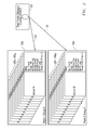
- FIG. 2 illustrates one exemplary embodiment for configuring multiple server rack systems 100 a and 100 b by remote administrator 128 in the form a data center manager console (DCMC) that in this embodiment acts as a power manager for server rack systems 100 a and 100 b .
- DCMC 128 may be a dedicated power IT power console, e.g., running on a server or desktop computer that communicates across network 124 .
- similar methodology and architecture may also be employed for configuring a single server rack system 100 or more than two server rack systems 100 , with each server rack system 100 including one or more blade server nodes.
- FIG. 128 may be a dedicated power IT power console, e.g., running on a server or desktop computer that communicates across network 124 .
- similar methodology and architecture may also be employed for configuring a single server rack system 100 or more than two server rack systems 100 , with each server rack system 100 including one or more blade server nodes.
- FIG. 128 may be a dedicated power IT power console, e.g.,
- server rack systems 100 a and 100 b are first provided and configured as individual rack systems, e.g., by IT personnel.
- remote administrator 128 begins by defining groups of information handling system nodes that are pooled together in a common credit/debit power pool, in this a first group is defined to include blade servers 180 1 to 180 N of server rack system 100 a , and a second group is defined to include blade servers 180 1 to 180 M of server rack system 100 b .
- the remote administrator 128 of FIG. 2 also may be employed to set various power allocation information characteristics for each of the defined groups.
- power allocation information characteristics include, but are not limited to, total group (e.g., rack) level power limit, individual node (e.g., server) power caps, individual node (e.g., server) maximum power levels, individual node (e.g., server) minimum power levels, individual node (e.g., server) time limit policies governing when to credit and debit power, priority for power allocation, etc.
- values of individual characteristics e.g., priority policies, power caps, maximum power levels, minimum power levels, time limit policies, etc.
- each of blade servers 180 of a server rack system 100 a and/or 100 b may be self-configured by management subsystem 132 (e.g., via iDRAC) of FIG. 1 rather than by remote administrator 128 .
- blade server nodes 180 1 to 180 M of a server rack system 100 may characterize themselves based on deployed configuration by running a characterization profile routine during the BIOS initialization stage, e.g., each server node 180 may use power management bus (PMbus) supplies and smart voltage regulator/s (VRs) to monitor and characterize itself.
- PMbus power management bus
- VRs voltage regulator/s
- Information technology (IT) management or other user/s may then define or otherwise provide a priority to each server node 180 based on the workload that the given server node 180 will be running, for example, an Exchange server may be assigned a high priority than a Print server.
- Internode communications and algorithms may then be used to self-adjust the server nodes 180 of a given rack 100 to ensure the highest level priority servers 180 receive a higher percentage of the overall rack level power.
- the BMC 126 of each respective given blade server 180 acts in this embodiment to receive group definition and other power allocation information from remote administrator 128 or by any other suitable technique.
- the IP addresses of the other servers 180 in the same defined power pool group are communicated to the BMC 126 of each server 180 in the same group, and it is these IP addresses with which each server 180 in the group will share (e.g., loan and borrow) power credits.
- Each BMC 126 of each server node 180 may retain (e.g., in memory) the IP address information provided to it (e.g., both IP address of the BMC 126 of the individual server node 180 as well as the IP addresses of the BMCs of each of the other server nodes of the same defined group).
- Each BMC 126 may also retain other power allocation information characteristics such as group (e.g., rack) power limit, individual server node initial power cap, individual server node maximum power consumption limit, individual server node minimum power consumption limit, one or more policies for the individual server node 180 (e.g., time limit policies, priority policies, etc.), etc.
- each BMC 126 of each individual server 180 may also maintain real time power usage statistics for the individual server 180 , e.g., such as server power used counter, server power available counter, etc.
- at least one server 180 may be configured to act as a centralized gateway that performs the task/s of a rack level gateway.
- a server node 180 designated as a rack level gateway may be configured to provide the coordination point for an entire rack 100 as an option. Acting as a traffic cop or arbitrary, all other server nodes 180 in the rack 100 may alternately report their power statistics to the gateway, and may request power from the gateway versus using a peer-peer to method as described elsewhere herein.
- FIG. 3 illustrates one embodiment of server rack system 100 a of FIG. 2 as it may exist once configured with power allocation information to allow real time self-management and sharing of power credits and debits in a peer-to-peer fashion among the defined power group that includes server nodes 180 1 - 180 N .
- server nodes 180 1 - 180 N may now communicate amongst themselves to dynamically release power credits and claim power debits within the defined power group of rack system 100 a , e.g., the BMC 126 of each respective individual server node 180 may release power credits to the BMCs 126 of other server nodes 180 of the same power group, and may claim power debits from the BMCs 126 of other server nodes 180 in the same power group in real time and as needed.
- server nodes 180 1 , 180 3 and 180 N have been assigned highest priority (of 1) for power allocation, server node 180 2 has been assigned an intermediate priority (of 2) for power allocation, and server node 180 4 has been assigned lowest priority (of 3) for power allocation.
- any available power credits from the power pool will be first used to address the power needs of the highest priority servers 180 1 , 180 3 and 180 N , then any remaining power credits will next be used to address the power needs of the intermediate priority server 180 2 , and thereafter any remaining power credits that may be left will be used to address the power needs of the lowest priority server 180 4 .
- FIG. 4 illustrates an example condition under which server rack system 100 a of FIG. 2 may operate to dynamically allocate relative power consumption in real time between the multiple information handling system nodes 180 1 - 180 N .
- server node 180 1 is shown as being idle (consuming a current power level of 150 Watts which is below its capped power level of 500 Watts) for an idle time of 6 minutes.
- BMC 126 of server node 180 1 detects that server node 180 1 has not been consuming its capped power limit of 500 Watts for a period of time greater than its defined policy-defined time frame (e.g., which is 5 minutes in this case), then BMC 126 of server node 180 1 may implement revised power allocation characteristics 401 as shown.
- its defined policy-defined time frame e.g., which is 5 minutes in this case
- BMC 126 of server node 180 1 may temporarily change its capped power limit to a downward-revised capped power limit that in this case is equal to a pre-defined minimum power cap level (e.g., 200 Watts in this case), and also broadcast or otherwise advertise a corresponding available 300 Watt power credit to the other server nodes 180 1 - 180 N of the same defined power group of rack system 100 a .
- a current total amount of available power credits among the nodes of a power pool may be tracked and revised in real time, e.g., by using a Power Available counter maintained by each server node 180 in the power pool group of server rack system 100 a.
- the total available power credits for a power pool may be tracked and updated using any other suitable alternative methodology. It will also be understood that more than one increased power level and/or that more than one decreased power level may be defined for each information handling system node of a power pool. For example, in the example of FIGS. 3-4 , an intermediate increased power level of 650 Watts and/or an intermediate decreased power level of 350 Watts may be defined such that power credits and/or debits may be exchanged when less than a full 300 Watt power credit or debit is currently available.
- server node 180 2 is shown consuming a current power level of 500 Watts, which is equal to its capped power level of 500 Watts.
- BMC 126 of server node 180 2 may implement revised power allocation characteristics 402 as shown.
- BMC 126 of server node 180 2 may determine the current availability of power credits from other server nodes 180 1 - 180 N of the same power pool group.
- server node 180 2 may claim a 300 Watt power debit from the available power credits of the power pool, and temporarily upwardly revise its capped power limit to a pre-defined maximum power cap level (e.g., 800 Watts in this case) as shown by revised power allocation characteristics 402 .
- server node 180 2 may also broadcast or otherwise advertise a corresponding reduction of 300 Watts in the current total amount of available power credits for the other server nodes 180 1 - 180 N of the power group of rack system 100 a (e.g., to cause reduction of 300 Watts in a Power Available counter maintained by each server node in the power pool group).
- FIG. 5 illustrates an example condition under which server rack system 100 a of FIG. 2 may operate to dynamically re-allocate relative power consumption in real time upon further changes in power consumption requirements between the multiple information handling system nodes 180 1 - 180 N of FIG. 3 .
- server node 180 1 is shown no longer idle and is consuming an increased current power level of 200 Watts, which is equivalent to the temporary downward-revised capped power limit of revised power allocation characteristics 401 of FIG. 4 .
- BMC 126 of server node 180 1 may implement revised power allocation characteristics 403 as shown raising the current power to 200.
- BMC 126 of server node 180 1 has a current power consumption level that is sufficiently low to allow it to continue to make available a 300 Watt power credit to the power pool.
- revised power allocation characteristics 404 for server node 180 2 reflect that server node 180 2 continues to consume at a current power level of 800 with a temporary upwardly revised power cap of 800 Watts that was set in FIG. 4 by virtue of the available 300 Watt power debit retrieved from the power pool.
- FIG. 6 illustrates an alternative situation to FIG. 5 in which insufficient power credit is no longer currently available in the power pool to allow server 180 2 to claim a 300 Watt power debit to raise its capped power limit to a new power cap of 800 Watts as was possible in the situation of FIGS. 4-5 . Rather, in the case of FIG. 6 , server node 180 1 is now consuming its capped power limit of 500 Watts. In such a case, BMC 126 of server node 180 1 may be configured to broadcast a reset command to force the BMCs 126 of all servers 180 1 - 180 N in the pool to release any extra power credits they have taken. As shown in FIG.
- server nodes 180 1 and 180 2 return to their original power capped levels as originally established during initial setup. This is illustrated by revised power allocations 405 and 406 , which show that both server nodes 180 1 and 180 2 have returned to their original capped power levels of 500 Watts.
- FIGS. 3-6 illustrate reallocation of power between two server nodes 180 1 and 180 2 of rack server system 100 a .
- more than two information handling system nodes may be each tracking total available power pool credits and simultaneously releasing power credits and/or retrieving power debits in a similar manner from a common group power pool as real time operating conditions change.
- peer to peer acknowledgement for credit/debit changes may be made in one embodiment on a first come-first serve basis (subject to any assigned priority policy value) from information handling system node to information handling system node, as long as sufficient excess power capacity exists for the group.
- a time out mechanism may also be implemented in the event that one or more information handling system nodes go down.
- Such a time out mechanism may be employed as a backup mechanism to return power to the original state should a server node go offline while it has a credit/debit or has a system crash.
- a time out mechanism may be a defined maximum time that a credit/debit is to be allocated, e.g., such that a server node providing a credit knows when it is safe to take back power, or such that when a server node takes a power debit it knows how long it may keep that debit.
- a centralized power management entity that acts as a centralized power credit/debit location may be implemented by one or more processing devices (e.g., processor, microprocessor, controller, microcontroller, ASIC, FPGA, CPU, etc.).
- processing devices e.g., processor, microprocessor, controller, microcontroller, ASIC, FPGA, CPU, etc.
- Such a centralized power management entity may track and revise a current total amount of available power credits among the individual information handling system nodes of a defined power pool and arbitrate the exchange of power credits and debits between the individual information handling system nodes in a manner similar to that described in relation to the distributed management architecture of FIGS. 3-6 , but from a centralized management entity instead.
- a centralized power management entity may be implemented, for example, by a processing device/s separate from any processing devices of the individual information handling system nodes of a defined group of information handling system nodes (e.g., such as management subsystem 132 of server rack system 100 of FIG. 1 ), or may be implemented by a processing device of one of the information handling system nodes included in a defined power pool (e.g., such as a BMC 126 of a designated one of server nodes 180 of rack server system 100 of FIG. 1 ).
- a processing device/s separate from any processing devices of the individual information handling system nodes of a defined group of information handling system nodes (e.g., such as management subsystem 132 of server rack system 100 of FIG. 1 ), or may be implemented by a processing device of one of the information handling system nodes included in a defined power pool (e.g., such as a BMC 126 of a designated one of server nodes 180 of rack server system 100 of FIG. 1 ).
- the lowest IP address member node of a pool of information handling system nodes may be selected as the gate keeper of power credits/debits, and all requests for power credits and debits may be communicated and acknowledge from one central information handling system node in the power pool group.
- one or more steps or tasks of the techniques and methodology disclosed herein may be implemented by a computer program of instructions (e.g., computer readable code such as firmware code or software code) embodied in a non-transitory tangible computer readable medium (e.g., optical disk, magnetic disk, non-volatile memory device, etc.), in which the computer program comprising instructions are configured when executed (e.g., executed on a processing device of an information handling system such as a processor, microprocessor, microcontroller, controller, etc.) to perform the one or more steps.
- a computer program of instructions e.g., computer readable code such as firmware code or software code
- a non-transitory tangible computer readable medium e.g., optical disk, magnetic disk, non-volatile memory device, etc.
- the computer program comprising instructions are configured when executed (e.g., executed on a processing device of an information handling system such as a processor, microprocessor, microcontroller, controller, etc.) to perform the one or more steps.
- a computer program of instructions may be stored in or on the non-transitory computer-readable medium residing on or accessible by an information handling system for instructing the information handling system to execute the computer program of instructions.
- the computer program of instructions may include an ordered listing of executable instructions for implementing logical functions in the information handling system.
- the executable instructions may comprise a plurality of code segments operable to instruct the information handling system to perform the methodology disclosed herein. It will also be understood that one or more steps of the present methodology may be employed in one or more code segments of the present computer program. For example, a code segment executed by the information handling system may include one or more steps of the disclosed methodology.
- an information handling system may include any instrumentality or aggregate of instrumentalities operable to compute, classify, process, transmit, receive, retrieve, originate, switch, store, display, manifest, detect, record, reproduce, handle, or utilize any form of information, intelligence, or data for business, scientific, control, entertainment, or other purposes.
- an information handling system may be a personal computer, a PDA, a consumer electronic device, a network storage device, or any other suitable device and may vary in size, shape, performance, functionality, and price.
- the information handling system may include memory, one or more processing resources such as a central processing unit (CPU) or hardware or software control logic.
- CPU central processing unit
- Additional components of the information handling system may include one or more storage devices, one or more communications ports for communicating with external devices as well as various input and output (I/O) devices, such as a keyboard, a mouse, and a video display.
- the information handling system may also include one or more buses operable to transmit communications between the various hardware components.
Abstract
Description
Claims (23)
Priority Applications (1)
| Application Number | Priority Date | Filing Date | Title |
|---|---|---|---|
| US13/477,837 US8843772B2 (en) | 2012-05-22 | 2012-05-22 | Systems and methods for dynamic power allocation in an information handling system environment |
Applications Claiming Priority (1)
| Application Number | Priority Date | Filing Date | Title |
|---|---|---|---|
| US13/477,837 US8843772B2 (en) | 2012-05-22 | 2012-05-22 | Systems and methods for dynamic power allocation in an information handling system environment |
Publications (2)
| Publication Number | Publication Date |
|---|---|
| US20130318371A1 US20130318371A1 (en) | 2013-11-28 |
| US8843772B2 true US8843772B2 (en) | 2014-09-23 |
Family
ID=49622523
Family Applications (1)
| Application Number | Title | Priority Date | Filing Date |
|---|---|---|---|
| US13/477,837 Active 2033-01-12 US8843772B2 (en) | 2012-05-22 | 2012-05-22 | Systems and methods for dynamic power allocation in an information handling system environment |
Country Status (1)
| Country | Link |
|---|---|
| US (1) | US8843772B2 (en) |
Cited By (11)
| Publication number | Priority date | Publication date | Assignee | Title |
|---|---|---|---|---|
| US20140115357A1 (en) * | 2012-10-18 | 2014-04-24 | Huawei Technologies Co., Ltd. | Method and Apparatus for Adjusting Device Power Consumption |
| US20160380675A1 (en) * | 2014-06-30 | 2016-12-29 | Intel Corporation | Methods and systems for server power line communication |
| US9880599B1 (en) | 2016-10-12 | 2018-01-30 | International Business Machines Corporation | Priority-aware power capping for hierarchical power distribution networks |
| US20190041937A1 (en) * | 2017-08-02 | 2019-02-07 | Lenovo Enterprise Solutions (Singapore) Pte. Ltd. | Power allocation among computing devices |
| US10270071B2 (en) | 2016-09-02 | 2019-04-23 | Dell Products L.P. | Systems and methods for voltage regulated battery backup management |
| US10345888B2 (en) | 2017-03-15 | 2019-07-09 | International Business Machines Corporation | Power capping for power consumption devices with multiple power supplies |
| US10423204B2 (en) | 2017-03-15 | 2019-09-24 | International Business Machines Corporation | Enforcing power caps on computing devices with multiple power feeds |
| US10452117B1 (en) * | 2016-09-22 | 2019-10-22 | Apple Inc. | Processor energy management system |
| US20200033926A1 (en) * | 2018-07-27 | 2020-01-30 | Dell Products L.P. | System and method to maintain power cap while baseboard management controller reboots |
| EP3623945A1 (en) * | 2018-09-14 | 2020-03-18 | Quanta Computer Inc. | A method and system for dynamically allocating and optimizing power resources |
| US20220215484A1 (en) * | 2021-01-05 | 2022-07-07 | Saudi Arabian Oil Company | Systems and methods for monitoring and controlling electrical power consumption |
Families Citing this family (64)
| Publication number | Priority date | Publication date | Assignee | Title |
|---|---|---|---|---|
| US8849469B2 (en) | 2010-10-28 | 2014-09-30 | Microsoft Corporation | Data center system that accommodates episodic computation |
| US9003216B2 (en) * | 2011-10-03 | 2015-04-07 | Microsoft Technology Licensing, Llc | Power regulation of power grid via datacenter |
| US9697163B2 (en) * | 2012-07-03 | 2017-07-04 | Nxp Usa, Inc. | Data path configuration component, signal processing device and method therefor |
| TW201405295A (en) * | 2012-07-18 | 2014-02-01 | Hon Hai Prec Ind Co Ltd | Power supply circuit |
| US9494954B2 (en) * | 2012-07-26 | 2016-11-15 | Dell Products Lp | Thermal control systems and methods for information handling systems |
| US9625967B1 (en) * | 2012-09-25 | 2017-04-18 | EMC IP Holding Company LLC | Managing power reduction in data center components |
| US9134779B2 (en) * | 2012-11-21 | 2015-09-15 | International Business Machines Corporation | Power distribution management in a system on a chip |
| US9134778B2 (en) * | 2012-11-21 | 2015-09-15 | International Business Machines Corporation | Power distribution management in a system on a chip |
| US9298247B2 (en) * | 2012-11-27 | 2016-03-29 | International Business Machines Corporation | Distributed power budgeting |
| JP2014142840A (en) * | 2013-01-24 | 2014-08-07 | Fujitsu Ltd | Information processing device, power consumption control method, and program |
| WO2014163634A1 (en) * | 2013-04-03 | 2014-10-09 | Hewlett-Packard Development Company, L.P. | Zoneable power regulation |
| US20140344431A1 (en) * | 2013-05-16 | 2014-11-20 | Aspeed Technology Inc. | Baseboard management system architecture |
| US9568978B2 (en) * | 2013-09-26 | 2017-02-14 | Intel Corporation | Controlling power consumption in processor-based systems and components thereof |
| TW201520752A (en) * | 2013-11-29 | 2015-06-01 | Ibm | Power consumption control in computer system |
| US9405301B2 (en) | 2014-01-14 | 2016-08-02 | Dell Products Lp | Systems and methods for user modification of cooling device response in information handling systems |
| US9787172B2 (en) | 2014-06-19 | 2017-10-10 | Dell Products Lp | Methods and systems for implementing adaptive FET drive voltage optimization for power stages of multi-phase voltage regulator circuits |
| US9678555B2 (en) | 2014-06-19 | 2017-06-13 | Dell Products L.P. | Methods and systems for calibration of voltage regulator systems with multiple types of power stages |
| US9240722B2 (en) | 2014-06-19 | 2016-01-19 | Dell Products Lp | Methods and systems for improving light load efficiency for power stages of multi-phase voltage regulator circuits |
| US9979674B1 (en) * | 2014-07-08 | 2018-05-22 | Avi Networks | Capacity-based server selection |
| US10234835B2 (en) | 2014-07-11 | 2019-03-19 | Microsoft Technology Licensing, Llc | Management of computing devices using modulated electricity |
| US9933804B2 (en) | 2014-07-11 | 2018-04-03 | Microsoft Technology Licensing, Llc | Server installation as a grid condition sensor |
| US9823328B2 (en) | 2014-08-01 | 2017-11-21 | Dell Products Lp | Systems and methods of current sense calibration for voltage regulator circuits |
| US9036291B1 (en) | 2014-08-22 | 2015-05-19 | Dell Products, Lp | Systems and methods for asynchronous-frequency tracking of disk drive rotational vibration (RV) performance with position error signal (PES) |
| WO2016068994A1 (en) | 2014-10-31 | 2016-05-06 | Hewlett Packard Enterprise Development Lp | Combined backup power |
| US9727108B2 (en) * | 2015-03-13 | 2017-08-08 | Lenovo (Singapore) Pte. Ltd. | Supply of power from one device to another device |
| US9933826B2 (en) * | 2015-05-11 | 2018-04-03 | Hewlett Packard Enterprise Development Lp | Method and apparatus for managing nodal power in a high performance computer system |
| US10429909B2 (en) | 2015-06-01 | 2019-10-01 | Hewlett Packard Enterprise Development Lp | Managing power in a high performance computing system for resiliency and cooling |
| US10042410B2 (en) * | 2015-06-11 | 2018-08-07 | International Business Machines Corporation | Managing data center power consumption |
| US9588571B2 (en) * | 2015-07-08 | 2017-03-07 | Quanta Computer Inc. | Dynamic power supply management |
| US10691517B2 (en) * | 2015-07-17 | 2020-06-23 | Hewlett Packard Enterprise Development Lp | Operating frequency determination based on a warranty period |
| US10198061B2 (en) | 2015-09-01 | 2019-02-05 | Toshiba Memory Corporation | Storage and storage system |
| US10095293B2 (en) * | 2016-05-04 | 2018-10-09 | Dell Products L.P. | System and method for determining power supply capability |
| US10437303B2 (en) * | 2016-05-20 | 2019-10-08 | Dell Products L.P. | Systems and methods for chassis-level view of information handling system power capping |
| US10419320B2 (en) | 2016-06-30 | 2019-09-17 | Microsoft Technology Licensing, Llc | Infrastructure resource management system |
| US10361965B2 (en) | 2016-06-30 | 2019-07-23 | Microsoft Technology Licensing, Llc | Datacenter operations optimization system |
| US10048732B2 (en) * | 2016-06-30 | 2018-08-14 | Microsoft Technology Licensing, Llc | Datacenter power management system |
| US10200303B2 (en) | 2016-06-30 | 2019-02-05 | Microsoft Technology Licensing, Llc | Datacenter byproduct management interface system |
| US20190109720A1 (en) | 2016-07-26 | 2019-04-11 | Samsung Electronics Co., Ltd. | Modular system (switch boards and mid-plane) for supporting 50g or 100g ethernet speeds of fpga+ssd |
| US11461258B2 (en) * | 2016-09-14 | 2022-10-04 | Samsung Electronics Co., Ltd. | Self-configuring baseboard management controller (BMC) |
| US10210123B2 (en) | 2016-07-26 | 2019-02-19 | Samsung Electronics Co., Ltd. | System and method for supporting multi-path and/or multi-mode NMVe over fabrics devices |
| US10467052B2 (en) * | 2017-05-01 | 2019-11-05 | Red Hat, Inc. | Cluster topology aware container scheduling for efficient data transfer |
| US10423217B1 (en) * | 2017-07-14 | 2019-09-24 | Cisco Technology, Inc. | Dynamic power capping of multi-server nodes in a chassis based on real-time resource utilization |
| CN108121638A (en) * | 2017-12-21 | 2018-06-05 | 曙光信息产业股份有限公司 | Server flattens platform power consumption optimization method and device |
| US10877553B2 (en) * | 2018-04-13 | 2020-12-29 | Dell Products L.P. | Systems and methods for power control based on power consumption of storage devices |
| JP6949224B2 (en) * | 2018-06-27 | 2021-10-13 | 三菱電機株式会社 | Electric energy setting device, electric energy setting method, and program |
| CN109032807A (en) * | 2018-08-08 | 2018-12-18 | 郑州云海信息技术有限公司 | A kind of batch monitors the method and system of internal storage state and limitation power consumption of internal memory |
| CN109189636A (en) * | 2018-08-08 | 2019-01-11 | 郑州云海信息技术有限公司 | A kind of batch monitoring CPU state and the method and system for limiting CPU power consumption |
| CN109240892A (en) * | 2018-10-08 | 2019-01-18 | 郑州云海信息技术有限公司 | A kind of method and system of batch monitoring server complete machine state |
| US11188142B1 (en) * | 2018-12-11 | 2021-11-30 | Amazon Technologies, Inc. | Power management network for communication between racks in a data center |
| CN110399216B (en) * | 2019-06-27 | 2021-10-15 | 苏州浪潮智能科技有限公司 | Method, system and device for distributing power consumption of whole machine box and readable storage medium |
| US11099855B2 (en) * | 2019-10-23 | 2021-08-24 | American Megatrends International, Llc | System and method for updating files through a peer-to-peer network |
| US11157056B2 (en) * | 2019-11-01 | 2021-10-26 | Dell Products L.P. | System and method for monitoring a maximum load based on an aggregate load profile of a system |
| US11934242B2 (en) * | 2019-12-08 | 2024-03-19 | Nvidia Corporation | Intelligent data center including N independent coolable clusters having respective actual power demand (P ac) adjustable at, above or below an ostensible power demand (P os) |
| US11321022B2 (en) * | 2019-12-31 | 2022-05-03 | Kioxia Corporation | Systems and methods for scheduling flash operations |
| WO2021188850A1 (en) * | 2020-03-20 | 2021-09-23 | Virtual Power Systems, Inc. | Datacenter power management using current injection |
| US11429176B2 (en) * | 2020-05-14 | 2022-08-30 | Dell Products L.P. | Intelligent and predictive optimization of power needs across virtualized environments |
| US11327545B2 (en) * | 2020-06-19 | 2022-05-10 | Dell Products L.P. | Automated management of power distribution during a power crisis |
| US11522727B2 (en) * | 2020-10-14 | 2022-12-06 | Juniper Networks, Inc. | Cooperative power management |
| US20220269298A1 (en) * | 2021-02-23 | 2022-08-25 | Microsoft Technology Licensing, Llc | Activity smoothener circuit controlling rates of change of localized processing activity in an integrated circuit (ic), and related methods |
| US20210349512A1 (en) * | 2021-07-26 | 2021-11-11 | Intel Corporation | System, Apparatus And Methods For Power Communications According To A CXL Power Protocol |
| US11915061B2 (en) * | 2021-10-26 | 2024-02-27 | Dell Products L.P. | Datacenter efficiency management system for migrating workload across nodes based on workload performance efficiency ranking |
| US20230126023A1 (en) * | 2021-10-26 | 2023-04-27 | Dell Products L.P. | Heterogeneous node group efficiency management system |
| US11844188B2 (en) * | 2021-12-13 | 2023-12-12 | Dell Products, L.P. | Distribution of available power to devices in a group |
| TWI803213B (en) * | 2022-02-25 | 2023-05-21 | 研華股份有限公司 | Network connection method based on intelligent baseboard management controller |
Citations (19)
| Publication number | Priority date | Publication date | Assignee | Title |
|---|---|---|---|---|
| US5532945A (en) * | 1994-06-17 | 1996-07-02 | Intel Corporation | Power budgetting in a computer system having removable devices |
| US6233625B1 (en) * | 1998-11-18 | 2001-05-15 | Compaq Computer Corporation | System and method for applying initialization power to SCSI devices |
| US20040255171A1 (en) * | 2003-06-13 | 2004-12-16 | Zimmer Vincent J. | Power management for clustered computing platforms |
| US20040255286A1 (en) * | 2003-06-13 | 2004-12-16 | Rothman Michael A. | Method for distributed update of firmware across a clustered platform infrastructure |
| US20060190532A1 (en) | 2005-02-23 | 2006-08-24 | Kalyana Chadalavada | Apparatus and methods for multiple user remote connections to an information handling system via a remote access controller |
| US20060212726A1 (en) * | 2005-03-16 | 2006-09-21 | International Business Machines Corporation | Method of governing power for multi-node computer system components |
| US20060212143A1 (en) | 2005-03-01 | 2006-09-21 | Nguyen Dung H | Apparatus and methods for instant messaging feature for communication between users in multiple-user information handling system |
| US20070260896A1 (en) * | 2006-05-04 | 2007-11-08 | Dell Products L.P. | Power profiling application for managing power allocation in an information handling system |
| US20080222435A1 (en) * | 2007-03-05 | 2008-09-11 | Joseph Edward Bolan | Power management in a power-constrained processing system |
| US7509505B2 (en) * | 2005-01-04 | 2009-03-24 | Cisco Technology, Inc. | Method and system for managing power delivery for power over Ethernet systems |
| US7539881B2 (en) * | 2006-04-15 | 2009-05-26 | Hewlett-Packard Development Company, L.P. | System and method for dynamically adjusting power caps for electronic components based on power consumption |
| US20100281183A1 (en) * | 2006-09-26 | 2010-11-04 | Nokia Corporation | Method and device for activating functions of a powered-off device via a serial data bus interface |
| US7861102B1 (en) | 2007-04-30 | 2010-12-28 | Hewlett-Packard Development Company, L.P. | Unified power management architecture |
| US7895455B2 (en) | 2007-06-25 | 2011-02-22 | Hewlett-Packard Development Company, L.P. | Dynamic converter control for efficient operation |
| US7904287B2 (en) | 2007-11-13 | 2011-03-08 | International Business Machines Corporation | Method and system for real-time prediction of power usage for a change to another performance state |
| US7979729B2 (en) | 2007-11-29 | 2011-07-12 | International Business Machines Corporation | Method for equalizing performance of computing components |
| US8006108B2 (en) | 2007-11-08 | 2011-08-23 | International Business Machines Corporation | Dynamic selection of group and device power limits |
| US20120166825A1 (en) * | 2010-06-23 | 2012-06-28 | 1E Limited | Controlling the Power Consumption of Computers |
| US20130226362A1 (en) * | 2012-02-23 | 2013-08-29 | Cisco Technology, Inc. | Large Scale Dynamic Power Budget Adjustments for Optimizing Power Utilization in a Data Center |
-
2012
- 2012-05-22 US US13/477,837 patent/US8843772B2/en active Active
Patent Citations (19)
| Publication number | Priority date | Publication date | Assignee | Title |
|---|---|---|---|---|
| US5532945A (en) * | 1994-06-17 | 1996-07-02 | Intel Corporation | Power budgetting in a computer system having removable devices |
| US6233625B1 (en) * | 1998-11-18 | 2001-05-15 | Compaq Computer Corporation | System and method for applying initialization power to SCSI devices |
| US20040255171A1 (en) * | 2003-06-13 | 2004-12-16 | Zimmer Vincent J. | Power management for clustered computing platforms |
| US20040255286A1 (en) * | 2003-06-13 | 2004-12-16 | Rothman Michael A. | Method for distributed update of firmware across a clustered platform infrastructure |
| US7509505B2 (en) * | 2005-01-04 | 2009-03-24 | Cisco Technology, Inc. | Method and system for managing power delivery for power over Ethernet systems |
| US20060190532A1 (en) | 2005-02-23 | 2006-08-24 | Kalyana Chadalavada | Apparatus and methods for multiple user remote connections to an information handling system via a remote access controller |
| US20060212143A1 (en) | 2005-03-01 | 2006-09-21 | Nguyen Dung H | Apparatus and methods for instant messaging feature for communication between users in multiple-user information handling system |
| US20060212726A1 (en) * | 2005-03-16 | 2006-09-21 | International Business Machines Corporation | Method of governing power for multi-node computer system components |
| US7539881B2 (en) * | 2006-04-15 | 2009-05-26 | Hewlett-Packard Development Company, L.P. | System and method for dynamically adjusting power caps for electronic components based on power consumption |
| US20070260896A1 (en) * | 2006-05-04 | 2007-11-08 | Dell Products L.P. | Power profiling application for managing power allocation in an information handling system |
| US20100281183A1 (en) * | 2006-09-26 | 2010-11-04 | Nokia Corporation | Method and device for activating functions of a powered-off device via a serial data bus interface |
| US20080222435A1 (en) * | 2007-03-05 | 2008-09-11 | Joseph Edward Bolan | Power management in a power-constrained processing system |
| US7861102B1 (en) | 2007-04-30 | 2010-12-28 | Hewlett-Packard Development Company, L.P. | Unified power management architecture |
| US7895455B2 (en) | 2007-06-25 | 2011-02-22 | Hewlett-Packard Development Company, L.P. | Dynamic converter control for efficient operation |
| US8006108B2 (en) | 2007-11-08 | 2011-08-23 | International Business Machines Corporation | Dynamic selection of group and device power limits |
| US7904287B2 (en) | 2007-11-13 | 2011-03-08 | International Business Machines Corporation | Method and system for real-time prediction of power usage for a change to another performance state |
| US7979729B2 (en) | 2007-11-29 | 2011-07-12 | International Business Machines Corporation | Method for equalizing performance of computing components |
| US20120166825A1 (en) * | 2010-06-23 | 2012-06-28 | 1E Limited | Controlling the Power Consumption of Computers |
| US20130226362A1 (en) * | 2012-02-23 | 2013-08-29 | Cisco Technology, Inc. | Large Scale Dynamic Power Budget Adjustments for Optimizing Power Utilization in a Data Center |
Non-Patent Citations (1)
| Title |
|---|
| Wikipedia, "Blade Server", Printed from Internet Feb. 24, 2012, 6 pgs. |
Cited By (19)
| Publication number | Priority date | Publication date | Assignee | Title |
|---|---|---|---|---|
| US20140115357A1 (en) * | 2012-10-18 | 2014-04-24 | Huawei Technologies Co., Ltd. | Method and Apparatus for Adjusting Device Power Consumption |
| US9207744B2 (en) * | 2012-10-18 | 2015-12-08 | Huawei Technologies Co., Ltd. | Method and apparatus for adjusting device power consumption |
| US20160380675A1 (en) * | 2014-06-30 | 2016-12-29 | Intel Corporation | Methods and systems for server power line communication |
| US9933829B2 (en) * | 2014-06-30 | 2018-04-03 | Intel Corporation | Methods and systems for server power line communication |
| US10963031B2 (en) | 2014-06-30 | 2021-03-30 | Intel Corporation | Methods and systems for server power line communication |
| US10270071B2 (en) | 2016-09-02 | 2019-04-23 | Dell Products L.P. | Systems and methods for voltage regulated battery backup management |
| US10452117B1 (en) * | 2016-09-22 | 2019-10-22 | Apple Inc. | Processor energy management system |
| US9880599B1 (en) | 2016-10-12 | 2018-01-30 | International Business Machines Corporation | Priority-aware power capping for hierarchical power distribution networks |
| US10423204B2 (en) | 2017-03-15 | 2019-09-24 | International Business Machines Corporation | Enforcing power caps on computing devices with multiple power feeds |
| US10345888B2 (en) | 2017-03-15 | 2019-07-09 | International Business Machines Corporation | Power capping for power consumption devices with multiple power supplies |
| US10884468B2 (en) * | 2017-08-02 | 2021-01-05 | Lenovo Enterprise Solutions (Singapore) Pte. Ltd. | Power allocation among computing devices |
| US20190041937A1 (en) * | 2017-08-02 | 2019-02-07 | Lenovo Enterprise Solutions (Singapore) Pte. Ltd. | Power allocation among computing devices |
| US20200033926A1 (en) * | 2018-07-27 | 2020-01-30 | Dell Products L.P. | System and method to maintain power cap while baseboard management controller reboots |
| US10788876B2 (en) * | 2018-07-27 | 2020-09-29 | Dell Products L.P. | System and method to maintain power cap while baseboard management controller reboots |
| EP3623945A1 (en) * | 2018-09-14 | 2020-03-18 | Quanta Computer Inc. | A method and system for dynamically allocating and optimizing power resources |
| CN110908485A (en) * | 2018-09-14 | 2020-03-24 | 广达电脑股份有限公司 | Method and system for dynamically allocating and optimizing power resources and machine readable medium |
| US10884469B2 (en) | 2018-09-14 | 2021-01-05 | Quanta Computer Inc. | Method and system for dynamically allocating and optimizing power resources |
| US20220215484A1 (en) * | 2021-01-05 | 2022-07-07 | Saudi Arabian Oil Company | Systems and methods for monitoring and controlling electrical power consumption |
| US11580610B2 (en) * | 2021-01-05 | 2023-02-14 | Saudi Arabian Oil Company | Systems and methods for monitoring and controlling electrical power consumption |
Also Published As
| Publication number | Publication date |
|---|---|
| US20130318371A1 (en) | 2013-11-28 |
Similar Documents
| Publication | Publication Date | Title |
|---|---|---|
| US8843772B2 (en) | Systems and methods for dynamic power allocation in an information handling system environment | |
| JP3978199B2 (en) | Resource utilization and application performance monitoring system and monitoring method | |
| US11023143B2 (en) | Node interconnection apparatus, resource control node, and server system | |
| US8713334B2 (en) | Demand based power allocation | |
| CN107003887B (en) | CPU overload setting and cloud computing workload scheduling mechanism | |
| US9395786B2 (en) | Cross-layer power management in a multi-layer system | |
| CN102844724B (en) | Power supply in managing distributed computing system | |
| US9588571B2 (en) | Dynamic power supply management | |
| US9904351B2 (en) | Systems and methods for power supply configuration and control | |
| US7308591B2 (en) | Power management of multi-processor servers | |
| US6990666B2 (en) | Near on-line server | |
| US9329910B2 (en) | Distributed power delivery | |
| US8140817B2 (en) | Dynamic logical partition management for NUMA machines and clusters | |
| US8473768B2 (en) | Power control apparatus and method for cluster system | |
| CN106133693B (en) | Moving method, device and the equipment of virtual machine | |
| JP2016526735A (en) | Virtual hadoop manager | |
| US20200042608A1 (en) | Distributed file system load balancing based on available node capacity | |
| US9635102B2 (en) | Broker module for managing and monitoring resources between internet service providers | |
| US11657013B2 (en) | Inter-baseboard management controller (BMC) integration for high performance computing platforms | |
| US20210365301A1 (en) | System and method for power and thermal management of disaggregated server subsystems | |
| US11809289B2 (en) | High-availability (HA) management networks for high performance computing platforms | |
| US11327549B2 (en) | Method and apparatus for improving power management by controlling operations of an uninterruptible power supply in a data center | |
| US20230122697A1 (en) | Power throttling of high performance computing (hpc) platform components | |
| US20230121562A1 (en) | Telemetry of artificial intelligence (ai) and/or machine learning (ml) workloads | |
| Hatwar et al. | Approach towards VM management for green computing |
Legal Events
| Date | Code | Title | Description |
|---|---|---|---|
| AS | Assignment |
Owner name: DELL PRODUCTS L.P., TEXAS Free format text: ASSIGNMENT OF ASSIGNORS INTEREST;ASSIGNOR:HORMUTH, ROBERT W.;REEL/FRAME:028253/0852 Effective date: 20120521 |
|
| FEPP | Fee payment procedure |
Free format text: PAYOR NUMBER ASSIGNED (ORIGINAL EVENT CODE: ASPN); ENTITY STATUS OF PATENT OWNER: LARGE ENTITY |
|
| AS | Assignment |
Owner name: BANK OF AMERICA, N.A., AS ADMINISTRATIVE AGENT, TEXAS Free format text: PATENT SECURITY AGREEMENT (ABL);ASSIGNORS:DELL INC.;APPASSURE SOFTWARE, INC.;ASAP SOFTWARE EXPRESS, INC.;AND OTHERS;REEL/FRAME:031898/0001 Effective date: 20131029 Owner name: BANK OF NEW YORK MELLON TRUST COMPANY, N.A., AS FIRST LIEN COLLATERAL AGENT, TEXAS Free format text: PATENT SECURITY AGREEMENT (NOTES);ASSIGNORS:APPASSURE SOFTWARE, INC.;ASAP SOFTWARE EXPRESS, INC.;BOOMI, INC.;AND OTHERS;REEL/FRAME:031897/0348 Effective date: 20131029 Owner name: BANK OF AMERICA, N.A., AS COLLATERAL AGENT, NORTH CAROLINA Free format text: PATENT SECURITY AGREEMENT (TERM LOAN);ASSIGNORS:DELL INC.;APPASSURE SOFTWARE, INC.;ASAP SOFTWARE EXPRESS, INC.;AND OTHERS;REEL/FRAME:031899/0261 Effective date: 20131029 Owner name: BANK OF NEW YORK MELLON TRUST COMPANY, N.A., AS FI Free format text: PATENT SECURITY AGREEMENT (NOTES);ASSIGNORS:APPASSURE SOFTWARE, INC.;ASAP SOFTWARE EXPRESS, INC.;BOOMI, INC.;AND OTHERS;REEL/FRAME:031897/0348 Effective date: 20131029 Owner name: BANK OF AMERICA, N.A., AS COLLATERAL AGENT, NORTH Free format text: PATENT SECURITY AGREEMENT (TERM LOAN);ASSIGNORS:DELL INC.;APPASSURE SOFTWARE, INC.;ASAP SOFTWARE EXPRESS, INC.;AND OTHERS;REEL/FRAME:031899/0261 Effective date: 20131029 Owner name: BANK OF AMERICA, N.A., AS ADMINISTRATIVE AGENT, TE Free format text: PATENT SECURITY AGREEMENT (ABL);ASSIGNORS:DELL INC.;APPASSURE SOFTWARE, INC.;ASAP SOFTWARE EXPRESS, INC.;AND OTHERS;REEL/FRAME:031898/0001 Effective date: 20131029 |
|
| STCF | Information on status: patent grant |
Free format text: PATENTED CASE |
|
| AS | Assignment |
Owner name: APPASSURE SOFTWARE, INC., VIRGINIA Free format text: RELEASE BY SECURED PARTY;ASSIGNOR:BANK OF AMERICA, N.A., AS ADMINISTRATIVE AGENT;REEL/FRAME:040065/0216 Effective date: 20160907 Owner name: DELL MARKETING L.P., TEXAS Free format text: RELEASE BY SECURED PARTY;ASSIGNOR:BANK OF AMERICA, N.A., AS ADMINISTRATIVE AGENT;REEL/FRAME:040065/0216 Effective date: 20160907 Owner name: WYSE TECHNOLOGY L.L.C., CALIFORNIA Free format text: RELEASE BY SECURED PARTY;ASSIGNOR:BANK OF AMERICA, N.A., AS ADMINISTRATIVE AGENT;REEL/FRAME:040065/0216 Effective date: 20160907 Owner name: CREDANT TECHNOLOGIES, INC., TEXAS Free format text: RELEASE BY SECURED PARTY;ASSIGNOR:BANK OF AMERICA, N.A., AS ADMINISTRATIVE AGENT;REEL/FRAME:040065/0216 Effective date: 20160907 Owner name: COMPELLANT TECHNOLOGIES, INC., MINNESOTA Free format text: RELEASE BY SECURED PARTY;ASSIGNOR:BANK OF AMERICA, N.A., AS ADMINISTRATIVE AGENT;REEL/FRAME:040065/0216 Effective date: 20160907 Owner name: ASAP SOFTWARE EXPRESS, INC., ILLINOIS Free format text: RELEASE BY SECURED PARTY;ASSIGNOR:BANK OF AMERICA, N.A., AS ADMINISTRATIVE AGENT;REEL/FRAME:040065/0216 Effective date: 20160907 Owner name: DELL PRODUCTS L.P., TEXAS Free format text: RELEASE BY SECURED PARTY;ASSIGNOR:BANK OF AMERICA, N.A., AS ADMINISTRATIVE AGENT;REEL/FRAME:040065/0216 Effective date: 20160907 Owner name: DELL USA L.P., TEXAS Free format text: RELEASE BY SECURED PARTY;ASSIGNOR:BANK OF AMERICA, N.A., AS ADMINISTRATIVE AGENT;REEL/FRAME:040065/0216 Effective date: 20160907 Owner name: DELL INC., TEXAS Free format text: RELEASE BY SECURED PARTY;ASSIGNOR:BANK OF AMERICA, N.A., AS ADMINISTRATIVE AGENT;REEL/FRAME:040065/0216 Effective date: 20160907 Owner name: PEROT SYSTEMS CORPORATION, TEXAS Free format text: RELEASE BY SECURED PARTY;ASSIGNOR:BANK OF AMERICA, N.A., AS ADMINISTRATIVE AGENT;REEL/FRAME:040065/0216 Effective date: 20160907 Owner name: SECUREWORKS, INC., GEORGIA Free format text: RELEASE BY SECURED PARTY;ASSIGNOR:BANK OF AMERICA, N.A., AS ADMINISTRATIVE AGENT;REEL/FRAME:040065/0216 Effective date: 20160907 Owner name: DELL SOFTWARE INC., CALIFORNIA Free format text: RELEASE BY SECURED PARTY;ASSIGNOR:BANK OF AMERICA, N.A., AS ADMINISTRATIVE AGENT;REEL/FRAME:040065/0216 Effective date: 20160907 Owner name: FORCE10 NETWORKS, INC., CALIFORNIA Free format text: RELEASE BY SECURED PARTY;ASSIGNOR:BANK OF AMERICA, N.A., AS ADMINISTRATIVE AGENT;REEL/FRAME:040065/0216 Effective date: 20160907 |
|
| AS | Assignment |
Owner name: DELL INC., TEXAS Free format text: RELEASE BY SECURED PARTY;ASSIGNOR:BANK OF AMERICA, N.A., AS COLLATERAL AGENT;REEL/FRAME:040040/0001 Effective date: 20160907 Owner name: WYSE TECHNOLOGY L.L.C., CALIFORNIA Free format text: RELEASE BY SECURED PARTY;ASSIGNOR:BANK OF AMERICA, N.A., AS COLLATERAL AGENT;REEL/FRAME:040040/0001 Effective date: 20160907 Owner name: CREDANT TECHNOLOGIES, INC., TEXAS Free format text: RELEASE BY SECURED PARTY;ASSIGNOR:BANK OF AMERICA, N.A., AS COLLATERAL AGENT;REEL/FRAME:040040/0001 Effective date: 20160907 Owner name: ASAP SOFTWARE EXPRESS, INC., ILLINOIS Free format text: RELEASE BY SECURED PARTY;ASSIGNOR:BANK OF AMERICA, N.A., AS COLLATERAL AGENT;REEL/FRAME:040040/0001 Effective date: 20160907 Owner name: DELL USA L.P., TEXAS Free format text: RELEASE BY SECURED PARTY;ASSIGNOR:BANK OF AMERICA, N.A., AS COLLATERAL AGENT;REEL/FRAME:040040/0001 Effective date: 20160907 Owner name: DELL PRODUCTS L.P., TEXAS Free format text: RELEASE BY SECURED PARTY;ASSIGNOR:BANK OF AMERICA, N.A., AS COLLATERAL AGENT;REEL/FRAME:040040/0001 Effective date: 20160907 Owner name: COMPELLENT TECHNOLOGIES, INC., MINNESOTA Free format text: RELEASE BY SECURED PARTY;ASSIGNOR:BANK OF AMERICA, N.A., AS COLLATERAL AGENT;REEL/FRAME:040040/0001 Effective date: 20160907 Owner name: PEROT SYSTEMS CORPORATION, TEXAS Free format text: RELEASE BY SECURED PARTY;ASSIGNOR:BANK OF AMERICA, N.A., AS COLLATERAL AGENT;REEL/FRAME:040040/0001 Effective date: 20160907 Owner name: DELL MARKETING L.P., TEXAS Free format text: RELEASE BY SECURED PARTY;ASSIGNOR:BANK OF AMERICA, N.A., AS COLLATERAL AGENT;REEL/FRAME:040040/0001 Effective date: 20160907 Owner name: FORCE10 NETWORKS, INC., CALIFORNIA Free format text: RELEASE BY SECURED PARTY;ASSIGNOR:BANK OF AMERICA, N.A., AS COLLATERAL AGENT;REEL/FRAME:040040/0001 Effective date: 20160907 Owner name: APPASSURE SOFTWARE, INC., VIRGINIA Free format text: RELEASE BY SECURED PARTY;ASSIGNOR:BANK OF AMERICA, N.A., AS COLLATERAL AGENT;REEL/FRAME:040040/0001 Effective date: 20160907 Owner name: DELL SOFTWARE INC., CALIFORNIA Free format text: RELEASE BY SECURED PARTY;ASSIGNOR:BANK OF AMERICA, N.A., AS COLLATERAL AGENT;REEL/FRAME:040040/0001 Effective date: 20160907 Owner name: SECUREWORKS, INC., GEORGIA Free format text: RELEASE BY SECURED PARTY;ASSIGNOR:BANK OF AMERICA, N.A., AS COLLATERAL AGENT;REEL/FRAME:040040/0001 Effective date: 20160907 Owner name: COMPELLENT TECHNOLOGIES, INC., MINNESOTA Free format text: RELEASE BY SECURED PARTY;ASSIGNOR:BANK OF NEW YORK MELLON TRUST COMPANY, N.A., AS COLLATERAL AGENT;REEL/FRAME:040065/0618 Effective date: 20160907 Owner name: ASAP SOFTWARE EXPRESS, INC., ILLINOIS Free format text: RELEASE BY SECURED PARTY;ASSIGNOR:BANK OF NEW YORK MELLON TRUST COMPANY, N.A., AS COLLATERAL AGENT;REEL/FRAME:040065/0618 Effective date: 20160907 Owner name: DELL INC., TEXAS Free format text: RELEASE BY SECURED PARTY;ASSIGNOR:BANK OF NEW YORK MELLON TRUST COMPANY, N.A., AS COLLATERAL AGENT;REEL/FRAME:040065/0618 Effective date: 20160907 Owner name: DELL USA L.P., TEXAS Free format text: RELEASE BY SECURED PARTY;ASSIGNOR:BANK OF NEW YORK MELLON TRUST COMPANY, N.A., AS COLLATERAL AGENT;REEL/FRAME:040065/0618 Effective date: 20160907 Owner name: FORCE10 NETWORKS, INC., CALIFORNIA Free format text: RELEASE BY SECURED PARTY;ASSIGNOR:BANK OF NEW YORK MELLON TRUST COMPANY, N.A., AS COLLATERAL AGENT;REEL/FRAME:040065/0618 Effective date: 20160907 Owner name: APPASSURE SOFTWARE, INC., VIRGINIA Free format text: RELEASE BY SECURED PARTY;ASSIGNOR:BANK OF NEW YORK MELLON TRUST COMPANY, N.A., AS COLLATERAL AGENT;REEL/FRAME:040065/0618 Effective date: 20160907 Owner name: PEROT SYSTEMS CORPORATION, TEXAS Free format text: RELEASE BY SECURED PARTY;ASSIGNOR:BANK OF NEW YORK MELLON TRUST COMPANY, N.A., AS COLLATERAL AGENT;REEL/FRAME:040065/0618 Effective date: 20160907 Owner name: CREDANT TECHNOLOGIES, INC., TEXAS Free format text: RELEASE BY SECURED PARTY;ASSIGNOR:BANK OF NEW YORK MELLON TRUST COMPANY, N.A., AS COLLATERAL AGENT;REEL/FRAME:040065/0618 Effective date: 20160907 Owner name: DELL SOFTWARE INC., CALIFORNIA Free format text: RELEASE BY SECURED PARTY;ASSIGNOR:BANK OF NEW YORK MELLON TRUST COMPANY, N.A., AS COLLATERAL AGENT;REEL/FRAME:040065/0618 Effective date: 20160907 Owner name: DELL PRODUCTS L.P., TEXAS Free format text: RELEASE BY SECURED PARTY;ASSIGNOR:BANK OF NEW YORK MELLON TRUST COMPANY, N.A., AS COLLATERAL AGENT;REEL/FRAME:040065/0618 Effective date: 20160907 Owner name: DELL MARKETING L.P., TEXAS Free format text: RELEASE BY SECURED PARTY;ASSIGNOR:BANK OF NEW YORK MELLON TRUST COMPANY, N.A., AS COLLATERAL AGENT;REEL/FRAME:040065/0618 Effective date: 20160907 Owner name: SECUREWORKS, INC., GEORGIA Free format text: RELEASE BY SECURED PARTY;ASSIGNOR:BANK OF NEW YORK MELLON TRUST COMPANY, N.A., AS COLLATERAL AGENT;REEL/FRAME:040065/0618 Effective date: 20160907 Owner name: WYSE TECHNOLOGY L.L.C., CALIFORNIA Free format text: RELEASE BY SECURED PARTY;ASSIGNOR:BANK OF NEW YORK MELLON TRUST COMPANY, N.A., AS COLLATERAL AGENT;REEL/FRAME:040065/0618 Effective date: 20160907 |
|
| AS | Assignment |
Owner name: THE BANK OF NEW YORK MELLON TRUST COMPANY, N.A., AS NOTES COLLATERAL AGENT, TEXAS Free format text: SECURITY AGREEMENT;ASSIGNORS:ASAP SOFTWARE EXPRESS, INC.;AVENTAIL LLC;CREDANT TECHNOLOGIES, INC.;AND OTHERS;REEL/FRAME:040136/0001 Effective date: 20160907 Owner name: CREDIT SUISSE AG, CAYMAN ISLANDS BRANCH, AS COLLATERAL AGENT, NORTH CAROLINA Free format text: SECURITY AGREEMENT;ASSIGNORS:ASAP SOFTWARE EXPRESS, INC.;AVENTAIL LLC;CREDANT TECHNOLOGIES, INC.;AND OTHERS;REEL/FRAME:040134/0001 Effective date: 20160907 Owner name: CREDIT SUISSE AG, CAYMAN ISLANDS BRANCH, AS COLLAT Free format text: SECURITY AGREEMENT;ASSIGNORS:ASAP SOFTWARE EXPRESS, INC.;AVENTAIL LLC;CREDANT TECHNOLOGIES, INC.;AND OTHERS;REEL/FRAME:040134/0001 Effective date: 20160907 Owner name: THE BANK OF NEW YORK MELLON TRUST COMPANY, N.A., A Free format text: SECURITY AGREEMENT;ASSIGNORS:ASAP SOFTWARE EXPRESS, INC.;AVENTAIL LLC;CREDANT TECHNOLOGIES, INC.;AND OTHERS;REEL/FRAME:040136/0001 Effective date: 20160907 |
|
| MAFP | Maintenance fee payment |
Free format text: PAYMENT OF MAINTENANCE FEE, 4TH YEAR, LARGE ENTITY (ORIGINAL EVENT CODE: M1551) Year of fee payment: 4 |
|
| AS | Assignment |
Owner name: THE BANK OF NEW YORK MELLON TRUST COMPANY, N.A., T Free format text: SECURITY AGREEMENT;ASSIGNORS:CREDANT TECHNOLOGIES, INC.;DELL INTERNATIONAL L.L.C.;DELL MARKETING L.P.;AND OTHERS;REEL/FRAME:049452/0223 Effective date: 20190320 Owner name: THE BANK OF NEW YORK MELLON TRUST COMPANY, N.A., TEXAS Free format text: SECURITY AGREEMENT;ASSIGNORS:CREDANT TECHNOLOGIES, INC.;DELL INTERNATIONAL L.L.C.;DELL MARKETING L.P.;AND OTHERS;REEL/FRAME:049452/0223 Effective date: 20190320 |
|
| AS | Assignment |
Owner name: THE BANK OF NEW YORK MELLON TRUST COMPANY, N.A., TEXAS Free format text: SECURITY AGREEMENT;ASSIGNORS:CREDANT TECHNOLOGIES INC.;DELL INTERNATIONAL L.L.C.;DELL MARKETING L.P.;AND OTHERS;REEL/FRAME:053546/0001 Effective date: 20200409 |
|
| AS | Assignment |
Owner name: WYSE TECHNOLOGY L.L.C., CALIFORNIA Free format text: RELEASE BY SECURED PARTY;ASSIGNOR:CREDIT SUISSE AG, CAYMAN ISLANDS BRANCH;REEL/FRAME:058216/0001 Effective date: 20211101 Owner name: SCALEIO LLC, MASSACHUSETTS Free format text: RELEASE BY SECURED PARTY;ASSIGNOR:CREDIT SUISSE AG, CAYMAN ISLANDS BRANCH;REEL/FRAME:058216/0001 Effective date: 20211101 Owner name: MOZY, INC., WASHINGTON Free format text: RELEASE BY SECURED PARTY;ASSIGNOR:CREDIT SUISSE AG, CAYMAN ISLANDS BRANCH;REEL/FRAME:058216/0001 Effective date: 20211101 Owner name: MAGINATICS LLC, CALIFORNIA Free format text: RELEASE BY SECURED PARTY;ASSIGNOR:CREDIT SUISSE AG, CAYMAN ISLANDS BRANCH;REEL/FRAME:058216/0001 Effective date: 20211101 Owner name: FORCE10 NETWORKS, INC., CALIFORNIA Free format text: RELEASE BY SECURED PARTY;ASSIGNOR:CREDIT SUISSE AG, CAYMAN ISLANDS BRANCH;REEL/FRAME:058216/0001 Effective date: 20211101 Owner name: EMC IP HOLDING COMPANY LLC, TEXAS Free format text: RELEASE BY SECURED PARTY;ASSIGNOR:CREDIT SUISSE AG, CAYMAN ISLANDS BRANCH;REEL/FRAME:058216/0001 Effective date: 20211101 Owner name: EMC CORPORATION, MASSACHUSETTS Free format text: RELEASE BY SECURED PARTY;ASSIGNOR:CREDIT SUISSE AG, CAYMAN ISLANDS BRANCH;REEL/FRAME:058216/0001 Effective date: 20211101 Owner name: DELL SYSTEMS CORPORATION, TEXAS Free format text: RELEASE BY SECURED PARTY;ASSIGNOR:CREDIT SUISSE AG, CAYMAN ISLANDS BRANCH;REEL/FRAME:058216/0001 Effective date: 20211101 Owner name: DELL SOFTWARE INC., CALIFORNIA Free format text: RELEASE BY SECURED PARTY;ASSIGNOR:CREDIT SUISSE AG, CAYMAN ISLANDS BRANCH;REEL/FRAME:058216/0001 Effective date: 20211101 Owner name: DELL PRODUCTS L.P., TEXAS Free format text: RELEASE BY SECURED PARTY;ASSIGNOR:CREDIT SUISSE AG, CAYMAN ISLANDS BRANCH;REEL/FRAME:058216/0001 Effective date: 20211101 Owner name: DELL MARKETING L.P., TEXAS Free format text: RELEASE BY SECURED PARTY;ASSIGNOR:CREDIT SUISSE AG, CAYMAN ISLANDS BRANCH;REEL/FRAME:058216/0001 Effective date: 20211101 Owner name: DELL INTERNATIONAL, L.L.C., TEXAS Free format text: RELEASE BY SECURED PARTY;ASSIGNOR:CREDIT SUISSE AG, CAYMAN ISLANDS BRANCH;REEL/FRAME:058216/0001 Effective date: 20211101 Owner name: DELL USA L.P., TEXAS Free format text: RELEASE BY SECURED PARTY;ASSIGNOR:CREDIT SUISSE AG, CAYMAN ISLANDS BRANCH;REEL/FRAME:058216/0001 Effective date: 20211101 Owner name: CREDANT TECHNOLOGIES, INC., TEXAS Free format text: RELEASE BY SECURED PARTY;ASSIGNOR:CREDIT SUISSE AG, CAYMAN ISLANDS BRANCH;REEL/FRAME:058216/0001 Effective date: 20211101 Owner name: AVENTAIL LLC, CALIFORNIA Free format text: RELEASE BY SECURED PARTY;ASSIGNOR:CREDIT SUISSE AG, CAYMAN ISLANDS BRANCH;REEL/FRAME:058216/0001 Effective date: 20211101 Owner name: ASAP SOFTWARE EXPRESS, INC., ILLINOIS Free format text: RELEASE BY SECURED PARTY;ASSIGNOR:CREDIT SUISSE AG, CAYMAN ISLANDS BRANCH;REEL/FRAME:058216/0001 Effective date: 20211101 |
|
| MAFP | Maintenance fee payment |
Free format text: PAYMENT OF MAINTENANCE FEE, 8TH YEAR, LARGE ENTITY (ORIGINAL EVENT CODE: M1552); ENTITY STATUS OF PATENT OWNER: LARGE ENTITY Year of fee payment: 8 |
|
| AS | Assignment |
Owner name: SCALEIO LLC, MASSACHUSETTS Free format text: RELEASE OF SECURITY INTEREST IN PATENTS PREVIOUSLY RECORDED AT REEL/FRAME (040136/0001);ASSIGNOR:THE BANK OF NEW YORK MELLON TRUST COMPANY, N.A., AS NOTES COLLATERAL AGENT;REEL/FRAME:061324/0001 Effective date: 20220329 Owner name: EMC IP HOLDING COMPANY LLC (ON BEHALF OF ITSELF AND AS SUCCESSOR-IN-INTEREST TO MOZY, INC.), TEXAS Free format text: RELEASE OF SECURITY INTEREST IN PATENTS PREVIOUSLY RECORDED AT REEL/FRAME (040136/0001);ASSIGNOR:THE BANK OF NEW YORK MELLON TRUST COMPANY, N.A., AS NOTES COLLATERAL AGENT;REEL/FRAME:061324/0001 Effective date: 20220329 Owner name: EMC CORPORATION (ON BEHALF OF ITSELF AND AS SUCCESSOR-IN-INTEREST TO MAGINATICS LLC), MASSACHUSETTS Free format text: RELEASE OF SECURITY INTEREST IN PATENTS PREVIOUSLY RECORDED AT REEL/FRAME (040136/0001);ASSIGNOR:THE BANK OF NEW YORK MELLON TRUST COMPANY, N.A., AS NOTES COLLATERAL AGENT;REEL/FRAME:061324/0001 Effective date: 20220329 Owner name: DELL MARKETING CORPORATION (SUCCESSOR-IN-INTEREST TO FORCE10 NETWORKS, INC. AND WYSE TECHNOLOGY L.L.C.), TEXAS Free format text: RELEASE OF SECURITY INTEREST IN PATENTS PREVIOUSLY RECORDED AT REEL/FRAME (040136/0001);ASSIGNOR:THE BANK OF NEW YORK MELLON TRUST COMPANY, N.A., AS NOTES COLLATERAL AGENT;REEL/FRAME:061324/0001 Effective date: 20220329 Owner name: DELL PRODUCTS L.P., TEXAS Free format text: RELEASE OF SECURITY INTEREST IN PATENTS PREVIOUSLY RECORDED AT REEL/FRAME (040136/0001);ASSIGNOR:THE BANK OF NEW YORK MELLON TRUST COMPANY, N.A., AS NOTES COLLATERAL AGENT;REEL/FRAME:061324/0001 Effective date: 20220329 Owner name: DELL INTERNATIONAL L.L.C., TEXAS Free format text: RELEASE OF SECURITY INTEREST IN PATENTS PREVIOUSLY RECORDED AT REEL/FRAME (040136/0001);ASSIGNOR:THE BANK OF NEW YORK MELLON TRUST COMPANY, N.A., AS NOTES COLLATERAL AGENT;REEL/FRAME:061324/0001 Effective date: 20220329 Owner name: DELL USA L.P., TEXAS Free format text: RELEASE OF SECURITY INTEREST IN PATENTS PREVIOUSLY RECORDED AT REEL/FRAME (040136/0001);ASSIGNOR:THE BANK OF NEW YORK MELLON TRUST COMPANY, N.A., AS NOTES COLLATERAL AGENT;REEL/FRAME:061324/0001 Effective date: 20220329 Owner name: DELL MARKETING L.P. (ON BEHALF OF ITSELF AND AS SUCCESSOR-IN-INTEREST TO CREDANT TECHNOLOGIES, INC.), TEXAS Free format text: RELEASE OF SECURITY INTEREST IN PATENTS PREVIOUSLY RECORDED AT REEL/FRAME (040136/0001);ASSIGNOR:THE BANK OF NEW YORK MELLON TRUST COMPANY, N.A., AS NOTES COLLATERAL AGENT;REEL/FRAME:061324/0001 Effective date: 20220329 Owner name: DELL MARKETING CORPORATION (SUCCESSOR-IN-INTEREST TO ASAP SOFTWARE EXPRESS, INC.), TEXAS Free format text: RELEASE OF SECURITY INTEREST IN PATENTS PREVIOUSLY RECORDED AT REEL/FRAME (040136/0001);ASSIGNOR:THE BANK OF NEW YORK MELLON TRUST COMPANY, N.A., AS NOTES COLLATERAL AGENT;REEL/FRAME:061324/0001 Effective date: 20220329 |
|
| AS | Assignment |
Owner name: SCALEIO LLC, MASSACHUSETTS Free format text: RELEASE OF SECURITY INTEREST IN PATENTS PREVIOUSLY RECORDED AT REEL/FRAME (045455/0001);ASSIGNOR:THE BANK OF NEW YORK MELLON TRUST COMPANY, N.A., AS NOTES COLLATERAL AGENT;REEL/FRAME:061753/0001 Effective date: 20220329 Owner name: EMC IP HOLDING COMPANY LLC (ON BEHALF OF ITSELF AND AS SUCCESSOR-IN-INTEREST TO MOZY, INC.), TEXAS Free format text: RELEASE OF SECURITY INTEREST IN PATENTS PREVIOUSLY RECORDED AT REEL/FRAME (045455/0001);ASSIGNOR:THE BANK OF NEW YORK MELLON TRUST COMPANY, N.A., AS NOTES COLLATERAL AGENT;REEL/FRAME:061753/0001 Effective date: 20220329 Owner name: EMC CORPORATION (ON BEHALF OF ITSELF AND AS SUCCESSOR-IN-INTEREST TO MAGINATICS LLC), MASSACHUSETTS Free format text: RELEASE OF SECURITY INTEREST IN PATENTS PREVIOUSLY RECORDED AT REEL/FRAME (045455/0001);ASSIGNOR:THE BANK OF NEW YORK MELLON TRUST COMPANY, N.A., AS NOTES COLLATERAL AGENT;REEL/FRAME:061753/0001 Effective date: 20220329 Owner name: DELL MARKETING CORPORATION (SUCCESSOR-IN-INTEREST TO FORCE10 NETWORKS, INC. AND WYSE TECHNOLOGY L.L.C.), TEXAS Free format text: RELEASE OF SECURITY INTEREST IN PATENTS PREVIOUSLY RECORDED AT REEL/FRAME (045455/0001);ASSIGNOR:THE BANK OF NEW YORK MELLON TRUST COMPANY, N.A., AS NOTES COLLATERAL AGENT;REEL/FRAME:061753/0001 Effective date: 20220329 Owner name: DELL PRODUCTS L.P., TEXAS Free format text: RELEASE OF SECURITY INTEREST IN PATENTS PREVIOUSLY RECORDED AT REEL/FRAME (045455/0001);ASSIGNOR:THE BANK OF NEW YORK MELLON TRUST COMPANY, N.A., AS NOTES COLLATERAL AGENT;REEL/FRAME:061753/0001 Effective date: 20220329 Owner name: DELL INTERNATIONAL L.L.C., TEXAS Free format text: RELEASE OF SECURITY INTEREST IN PATENTS PREVIOUSLY RECORDED AT REEL/FRAME (045455/0001);ASSIGNOR:THE BANK OF NEW YORK MELLON TRUST COMPANY, N.A., AS NOTES COLLATERAL AGENT;REEL/FRAME:061753/0001 Effective date: 20220329 Owner name: DELL USA L.P., TEXAS Free format text: RELEASE OF SECURITY INTEREST IN PATENTS PREVIOUSLY RECORDED AT REEL/FRAME (045455/0001);ASSIGNOR:THE BANK OF NEW YORK MELLON TRUST COMPANY, N.A., AS NOTES COLLATERAL AGENT;REEL/FRAME:061753/0001 Effective date: 20220329 Owner name: DELL MARKETING L.P. (ON BEHALF OF ITSELF AND AS SUCCESSOR-IN-INTEREST TO CREDANT TECHNOLOGIES, INC.), TEXAS Free format text: RELEASE OF SECURITY INTEREST IN PATENTS PREVIOUSLY RECORDED AT REEL/FRAME (045455/0001);ASSIGNOR:THE BANK OF NEW YORK MELLON TRUST COMPANY, N.A., AS NOTES COLLATERAL AGENT;REEL/FRAME:061753/0001 Effective date: 20220329 Owner name: DELL MARKETING CORPORATION (SUCCESSOR-IN-INTEREST TO ASAP SOFTWARE EXPRESS, INC.), TEXAS Free format text: RELEASE OF SECURITY INTEREST IN PATENTS PREVIOUSLY RECORDED AT REEL/FRAME (045455/0001);ASSIGNOR:THE BANK OF NEW YORK MELLON TRUST COMPANY, N.A., AS NOTES COLLATERAL AGENT;REEL/FRAME:061753/0001 Effective date: 20220329 |