US8842935B2 - Image capturing apparatus with image compensation and method thereof - Google Patents

Image capturing apparatus with image compensation and method thereof Download PDF

Info

Publication number
US8842935B2
US8842935B2 US11/525,055 US52505506A US8842935B2 US 8842935 B2 US8842935 B2 US 8842935B2 US 52505506 A US52505506 A US 52505506A US 8842935 B2 US8842935 B2 US 8842935B2
Authority
US
United States
Prior art keywords
image
tilt
capturer
compensation
region
Prior art date
Legal status (The legal status is an assumption and is not a legal conclusion. Google has not performed a legal analysis and makes no representation as to the accuracy of the status listed.)
Expired - Fee Related, expires
Application number
US11/525,055
Other versions
US20070065039A1 (en
Inventor
Tae-suh Park
Yeun-bae Kim
Min-Kyu Park
Current Assignee (The listed assignees may be inaccurate. Google has not performed a legal analysis and makes no representation or warranty as to the accuracy of the list.)
Samsung Electronics Co Ltd
Original Assignee
Samsung Electronics Co Ltd
Priority date (The priority date is an assumption and is not a legal conclusion. Google has not performed a legal analysis and makes no representation as to the accuracy of the date listed.)
Filing date
Publication date
Priority claimed from KR1020060084321A external-priority patent/KR100818989B1/en
Application filed by Samsung Electronics Co Ltd filed Critical Samsung Electronics Co Ltd
Assigned to SAMSUNG ELECTRONICS CO., LTD. reassignment SAMSUNG ELECTRONICS CO., LTD. ASSIGNMENT OF ASSIGNORS INTEREST (SEE DOCUMENT FOR DETAILS). Assignors: KIM, YEUN-BAE, PARK, MIN-KYU, PARK, TAE-SUH
Publication of US20070065039A1 publication Critical patent/US20070065039A1/en
Application granted granted Critical
Publication of US8842935B2 publication Critical patent/US8842935B2/en
Expired - Fee Related legal-status Critical Current
Adjusted expiration legal-status Critical

Links

Images

Classifications

    • HELECTRICITY
    • H04ELECTRIC COMMUNICATION TECHNIQUE
    • H04NPICTORIAL COMMUNICATION, e.g. TELEVISION
    • H04N7/00Television systems
    • H04N7/14Systems for two-way working
    • H04N7/141Systems for two-way working between two video terminals, e.g. videophone
    • H04N7/142Constructional details of the terminal equipment, e.g. arrangements of the camera and the display
    • HELECTRICITY
    • H04ELECTRIC COMMUNICATION TECHNIQUE
    • H04NPICTORIAL COMMUNICATION, e.g. TELEVISION
    • H04N23/00Cameras or camera modules comprising electronic image sensors; Control thereof
    • H04N23/60Control of cameras or camera modules
    • H04N23/61Control of cameras or camera modules based on recognised objects
    • HELECTRICITY
    • H04ELECTRIC COMMUNICATION TECHNIQUE
    • H04NPICTORIAL COMMUNICATION, e.g. TELEVISION
    • H04N23/00Cameras or camera modules comprising electronic image sensors; Control thereof
    • H04N23/60Control of cameras or camera modules
    • H04N23/63Control of cameras or camera modules by using electronic viewfinders
    • H04N5/23293
    • HELECTRICITY
    • H04ELECTRIC COMMUNICATION TECHNIQUE
    • H04NPICTORIAL COMMUNICATION, e.g. TELEVISION
    • H04N5/00Details of television systems
    • H04N5/222Studio circuitry; Studio devices; Studio equipment
    • H04N5/262Studio circuits, e.g. for mixing, switching-over, change of character of image, other special effects ; Cameras specially adapted for the electronic generation of special effects
    • H04N5/2628Alteration of picture size, shape, position or orientation, e.g. zooming, rotation, rolling, perspective, translation
    • HELECTRICITY
    • H04ELECTRIC COMMUNICATION TECHNIQUE
    • H04NPICTORIAL COMMUNICATION, e.g. TELEVISION
    • H04N7/00Television systems
    • H04N7/14Systems for two-way working
    • H04N7/141Systems for two-way working between two video terminals, e.g. videophone
    • H04N7/142Constructional details of the terminal equipment, e.g. arrangements of the camera and the display
    • H04N2007/145Handheld terminals

Definitions

  • the present invention relates to an image capturing apparatus with image compensation and a method thereof, and more particularly to an image capturing apparatus with image compensation and a method thereof, which can perform compensation of a user's facial image that is distorted in accordance with the position of a camera relative to an imaged object.
  • An IMT-2000 service which is the recently appearing next-generation mobile communication service, goes a step further to provide a video photography function between users of mobile communication devices having provided with cameras.
  • a user maintains a posture looking down toward the mobile communication device in hand because video telephony generally requires that the user continuously gaze at a communication partner's facial image displayed on the screen of the mobile communication device for several to tens of minutes. That is, the camera attached to the mobile communication device is mostly located below the user's face to capture the face of the user.
  • the image of the user's face in three-dimensions is distorted in such a manner that user's chin appears to be larger that it actually is and user's forehead appears to be more narrow than it actually is. This phenomenon is called perspective.
  • This distorted facial image is generally unnatural to users and may cause psychological rejection, which may delay the widespread use of video photography devices.
  • a mobile communication device is located below a user's face as illustrated in FIG. 1A , in front of the user's face as illustrated in FIG. 1B , or over (i.e., above) the user's face as illustrated in FIG. 1C , user's facial images captured by the mobile communication device may differ depending on the image capturing angles.
  • the user maintains a posture looking down on the mobile communication device i.e., if the user's facial image is captured by the mobile communication device that is positioned below the user's face, the user's chin appears to be larger and the user's forehead appears to be narrowed. That is, the user's chin appears to be wider than normal, while the user's forehead part appears to be narrowed.
  • Korean Patent Unexamined Publication No. 2004-0107890 discloses an image display compensation method for a mobile phone that adjusts a captured image parallel to user's eyes by automatically performing compensation of an image tilt appearing on a display screen of the mobile phone, in accordance with a relative rotating-angle difference between the user and the display screen of the mobile phone.
  • the displayed information can be recognized more easily and naturally by making the image parallel to the user's eyes, irrespective of the user's motion, by performing compensation on the rotating angle of the image that is seen through the mobile phone.
  • An aspect of the present invention provides an image capturing apparatus with image compensation and a method thereof, which can obtain an image desired by a user by determining the tilt status of a mobile communication device that captures the image of an object and performing compensation of the captured image in accordance with the determined tilt status of the device during a video telephony using the mobile communication device.
  • an image capturing apparatus with image compensation including an image capturing unit capturing an image of an object, a tilt determining unit determining a tilt of the image capturing unit against the object, and a compensation unit compensating the captured image in accordance with the determined tilt.
  • an image compensation method including capturing an image of an object, determining a tilt of the image capturing unit relative to the object, and compensating the captured image in accordance with the determined tilt.
  • a video telephony apparatus including an image capturing unit in a device, having an optical axis, and movable relative to a main body of the device, a tilt sensing unit in the main body sensing a tilt of the device relative to horizontal, a tilt calculation unit calculating a tilt of the image capturing unit based on an angle between a plane in the main body and the optical axis, and a compensation unit compensating for distortion of an image captured by the image capturing unit, based on the calculated tilt.
  • an image compensation method including sensing a first tilt angle which is an angle of a device in which an image capturing unit is installed relative to a horizontal plane, calculating a second tilt angle which is an angle of the image capturing unit relative to the device, capturing an image of an object and determining, based on the first and the second tilt angles, whether the image capturing unit is above the object, below the object or level with the object, and compensating for image distortion of the captured image when the image capturing unit is determined to be above or below the object.
  • FIGS. 1A to 1C are exemplary views illustrating images captured by a general video photography device
  • FIG. 2 is a block diagram illustrating the construction of an image capturing apparatus with image compensation according to an embodiment of the present invention
  • FIG. 3 is a view illustrating a tilt sensing unit according to an embodiment of the present invention.
  • FIG. 4 is a view illustrating an image capturing unit and a tilt sensing unit according to an embodiment of the present invention
  • FIG. 5 is a view illustrating a mobile communication device that captures images of an object according to an embodiment of the present invention
  • FIGS. 6A and 6B are views illustrating a captured image and a compensated image according to an embodiment of the present invention.
  • FIG. 7 is a view explaining divided parts of an image before being compensated according to an embodiment of the present invention.
  • FIG. 8 is a view explaining divided parts of a compensated image according to an embodiment of the present invention.
  • FIG. 9 is a view illustrating a surplus region in a display region according to an embodiment of the present invention.
  • FIGS. 10A to 10D are views explaining a method of processing a surplus region in a display region according to an embodiment of the present invention.
  • FIG. 11 is a block diagram illustrating the construction of an image capturing apparatus with image compensation according to an embodiment of the present invention.
  • FIG. 12 is a block diagram illustrating the construction of an image capturing apparatus with image compensation that is provided by adding a user compensation unit to the apparatus of FIG. 2 ;
  • FIG. 13 is a block diagram illustrating the construction of an image capturing apparatus with image compensation provided by adding a user compensation unit to the apparatus of FIG. 11 ;
  • FIG. 14 is a flowchart illustrating an image compensation method according to an embodiment of the present invention.
  • FIG. 15 is a flowchart illustrating an image compensation method according to an embodiment of the present invention.
  • an image capturing apparatus with image compensation is descried as being applied to devices such as a camera and mobile communication device (e.g., a mobile phone or a personal digital assistant (PDA)) having a camera attached thereto.
  • a camera and mobile communication device e.g., a mobile phone or a personal digital assistant (PDA)
  • PDA personal digital assistant
  • image compensation compensates the captured image in accordance with the position of a module that captures the image of an object.
  • a device that can sense the tilt against a specified reference plane such as, by way of non-limiting examples, a tilt sensor and an accelerometer, may be used, or a predetermined tilt may be used.
  • FIG. 2 is a block diagram illustrating the construction of an image capturing apparatus with image compensation according to an embodiment of the present invention.
  • the image capturing apparatus 100 with image compensation includes an image capturing unit 110 capturing the image of a specified object, a tilt sensing unit 120 sensing a tilt of a device in which the image capturing unit 110 is installed, a tilt determining unit 130 determining the tilt of the image capturing unit 110 in accordance with the sensed tilt, and a compensation unit 140 performing compensation of the captured image in accordance with the determined tilt.
  • the image capturing apparatus 100 also includes a first storage unit 150 storing captured images and compensated images, a second storage unit 160 storing tilts sensed by the tilt sensing unit 120 and tilts determined by the tilt determining unit 130 , and a transmission unit 170 transmitting the compensated image to an outside through a specified interface.
  • the first storage unit 150 , the second storage unit 160 , and the transmission unit are optional.
  • the object is a person.
  • the position of the image capturing unit 110 is a position looking up at the object.
  • the image capturing unit 110 is located below a plane on which the object is positioned and which is perpendicular to the direction of gravity. Accordingly, the image capturing unit 110 is located below the object to photograph the object.
  • these are merely non-limiting examples and that other orientations are contemplated.
  • the image capturing unit 110 may be, by way of a non-limiting example, a camera mounted in the mobile communication device, and images captured by the image capturing unit 110 may be stored in the first storage unit 150 .
  • the first storage unit 150 may be, by way of non-limiting examples, a cache, ROM, PROM, EPROM, EEPROM, flash, or SRAM.
  • a flash memory which is a nonvolatile memory, is used as the first storage unit 150 .
  • the image capturing unit 110 is mounted in the mobile communication device. However, it is to be understood that this is merely a non-limiting example to enhance understanding of the present embodiment.
  • the image capturing unit 110 can be applied to other devices that require the photographing of an object.
  • the tilt sensing unit 120 can sense the tilt of the device in which the image capturing unit 110 is installed against a specified reference plane by using a device that can sense the tilt against the specified reference plane, such as, by way of a non-limiting example, a tilt sensor and an accelerometer.
  • a device that can sense the tilt against the specified reference plane such as, by way of a non-limiting example, a tilt sensor and an accelerometer.
  • the reference plane is a plane that is perpendicular to the direction of gravity, on the assumption that the above-described sensors are is used as measuring means.
  • the reference plane is the ground. However, it is to be understood that this is merely a non-limiting example.
  • the tilt sensing unit 120 is installed inside the mobile communication device that is generally divided into a main body and a display device.
  • FIG. 3 is a view illustrating the tilt sensing unit 120 of FIG. 1 that senses the tilt of the main body of the mobile communication device against (i.e., relative to) the ground according to an embodiment of the present invention.
  • the tilt sensing unit 120 is installed in the main body 210 of the mobile communication device.
  • the tilt sensing unit 120 senses the tilt of the main body 210 of the mobile communication device against a plane that is parallel to the ground 220 .
  • the sensed tilt is stored in the second storage unit 160 .
  • the second storage unit 160 may be, by way of non-limiting examples, a cache, ROM, PROM, EPROM, EEPROM, flash, or SRAM.
  • the first storage unit 150 and the second storage unit are respectively constructed by hardware, but are not limited thereto. Rather, they may be, by way of a non-limiting example, integrated by hardware.
  • the tilt of the main body 210 of the mobile communication device against a plane that is parallel to the ground 220 is indicated “ ⁇ 1 ”.
  • the use of the ground as the reference to the tilt sensed by the tilt sensing unit 120 is a non-limiting example to facilitate the understanding of the present embodiment, and the reference plane to the tilt sensed by the tilt sensing unit 120 may be changed depending on the image capturing environment. As illustrated in FIG. 3 , ⁇ 1 has a negative value against the ground 220 . However, it is to be understood that ⁇ 1 need not be negative and could have a positive value.
  • the tilt determining unit 130 calculates the tilt of the image capturing unit 110 in consideration of the angle between the tilt sensing unit 120 and an optical axis 111 of FIG. 4 of the image capturing unit 110 , on the basis of the tilt sensing unit 120 .
  • the tilt calculated by the tilt determining unit 130 is stored in the second storage unit 160 in the same manner as the tilt sensed by the tilt sensing unit 120 .
  • the tilt of the image capturing unit 110 is calculated in consideration of the tilt sensed by the tilt sensing unit 120 and the angle between the tilt sensing unit 120 and the image capturing unit 110 , and thus it can be a measure of the position of the mobile communication device on the basis of a specified object. Specifically, referring to FIGS.
  • the tilt determining unit 130 calculates the angle between the tilt sensing unit 120 installed in the main body 210 of the mobile communication device and the optical axis 111 of the image capturing unit 120 , and then calculate the tilt of the image capturing unit 110 through the calculated angle and the tilt sensed by the tilt sensing unit 120 .
  • the angle between the image capturing unit 110 and the tilt sensing unit 120 is indicated “ ⁇ 2 ” as illustrated in FIG. 4 .
  • ⁇ 2 has a positive value against the tilt sensing unit 120 .
  • ⁇ 1 need not be negative and could have a positive value. Accordingly, the tilt calculated by the tilt determining unit 130 may be “ ⁇ 1 + ⁇ 2 ”.
  • the compensation unit 140 determines whether the image capturing unit 110 is located over (i.e. above) the object or below the object through “ ⁇ 1 + ⁇ 2 ” that is the tilt calculated by the tilt determining unit 130 . For example, if “ ⁇ 1 + ⁇ 2 ” is “0” on the assumption that the angle of the ground is “0”, it is determined that the optical axis of the image capturing unit 110 is parallel to the ground 220 .
  • the tilt sensing unit 120 is installed parallel to (i.e., in front of the optical axis of the image capturing unit 110 , the tilt sensed by the tilt sensing unit 120 may be considered to be the tilt of the ground reference camera. Accordingly, as illustrated in FIG.
  • the object is a user's face
  • an image of the user's face which is desired by the user, is an image captured by the image capturing unit 110 that is located over the user's face.
  • the optical axis 111 of the image capturing unit 110 points to the user.
  • the optical axis 111 of the image capturing unit 110 may also point to an object other than the user. Accordingly, the position of the image capturing unit 110 , which is determined depending on “ ⁇ 1 + ⁇ 2 ” may be changed by the optical axis 111 of the image capturing unit 110 .
  • the compensation unit 140 performs compensation of the captured image. Specifically, the compensation unit 140 determines whether the image desired by the user has been captured by comparing the tilt predetermined by the user or by default with the tilt calculated by the tilt determining unit 130 , and then it determines whether to perform the compensation in accordance with the result of judgment. If the calculated tilt is determined to be an angle that causes a perspective distortion of the facial image that is not desired by the user, the compensation unit 140 compensates for the generated distortion.
  • the captured image may be a distorted image in which the chin part 310 appears to be emphasized and the forehead part 320 appears to be narrowed.
  • the compensation unit 140 performs perspective compensation on the image as illustrated in FIG. 6A to provide a compensated image as illustrated in FIG. 6B .
  • the chin part 310 is reduced and the forehead part 320 is enlarged, in comparison to the distorted image of FIG. 6A .
  • the width of the chin part 310 of FIG. 6A is “A” and the width of the chin part 310 of FIG. 6B is “B”, the relation of “A>B” is effected between them.
  • the image compensation may also be performed so as to decrease the shadowing effect of the image by compulsory flashing through a camera flash or heightening of the brightness of the image during the image capturing, in addition to the image modification as illustrated in FIGS. 6A and 6B .
  • the compensation unit 140 can perform the image compensation in such a manner that the captured image is divided into lattices having the same spacing in horizontal and vertical directions on an xy-plane, and as y is increased from the original point (0, 0), the width W of the image and the lattice spacing d in the vertical direction is decreased. Accordingly, the compensation unit 140 can compensate the image captured through the image capturing unit 110 of FIG. 2 located below the user's face by widening the upper part of the image, narrowing the lower part of the image, and decreasing the lattice spacing d in the vertical direction, as illustrated in FIG. 8 .
  • the compensation unit 140 performs the compensation in a manner that the captured image is divided into two specified regions having the same shape and size as those of the image before the image compensation is performed and having different positions in upward and downward directions, respectively. Accordingly, the size of the lower region of the image becomes smaller than the size of the upper region of the image.
  • the compensation unit 140 can perform another process on the empty region in order to prevent the user from arousing psychological rejection against the empty region on which no image is displayed. For example, after the compensation according to FIGS. 7 and 8 is performed, the width of the lower part of the compensated image becomes narrower than the width of the upper part thereof.
  • the width of the upper part of the compensated image becomes equal to the width of the display region, but the width of the lower part of the compensated image becomes smaller than the width of the display region, thereby causing empty regions occur on both lower sides of the compensated image.
  • the compensation unit can perform the process on an empty region 430 occurring due to the different sizes of the display region 410 and the compensated image region 420 .
  • the empty region 430 may be filled with pixel values constituting the empty region 430 of the image 440 before being compensated as shown in FIG. 10A , the empty region is filled with pixel values of the compensated image existing at the closest position in the same row, on the basis of a specified pixel in the empty region as shown in FIG. 10B , or a specified frame 450 (e.g., a picture frame) may be overlaid along the circumference of the display region 410 so that the empty region is hidden as shown in FIG. 10C .
  • the overlay and the pixel values can be used in the case where the width of the upper part of the compensated image is equal to the width of the display region 410 .
  • the compensated image may be cut to match (i.e., cropped) the display region 410 after the captured image is compensated as shown in FIG. 10D .
  • the resolution of the image captured by the image capturing unit 110 is higher than the resolution of the display region 410 , and the image region that is not displayed in the display region 410 is removed after the image compensation.
  • a method of cutting out an unimpaired square region of the compensated image 420 , except for the empty region 430 , and enlarging cut region to a size enough to fill the display region 410 is contemplated.
  • the methods of processing the empty region 430 occurring due to the difference in size between the display region 410 and the compensated image 420 have been explained with reference to FIGS. 10A to 10D .
  • the processing of the empty region is not limited thereto.
  • the compensation unit 140 can perform the image compensation using a geometric transform technique and a perspective transform technique that is a kind of geometric transform technique.
  • a geometric transform technique and a perspective transform technique that is a kind of geometric transform technique.
  • these are merely non-limiting examples to facilitate the understanding of the present embodiment, and other diverse techniques can be used for the image compensation.
  • the perspective transform refers to typical matrix-based image transform algorithm
  • the image compensation may be performed according to Equation (1).
  • Equation (1) “x” and “y” denote specified points of an image before the image is compensated, “x′” and “y′” denote compensated points of the image, of which the positions have been changed by the perspective transform technique, and “w” denotes a weighted value.
  • values of m 00 , m 01 , m 02 , m 10 , m 11 , m 20 , and m 22 which are transform matrix coefficients of Equation (1), are adjusted on the basis of the ground reference tilt of the image capturing unit 110 , which have been finally calculated by the tilt determining unit 130 .
  • Equation (1) “x” and “y” are coordinates of an image before the image is compensated, and “x′” and “y′” are coordinates of the compensated image. Also, it is exemplified that a 3 ⁇ 3 matrix is used in Equation (1), but is not limited thereto. A 2 ⁇ 2 matrix may also be used. In this case, a user can re-compensate the image compensated by the compensation unit 140 by changing a horizontal magnitude value m 00 and a vertical magnitude value m 11 that are parameters that the user can actually change through the user compensation unit 190 .
  • the transmission unit 170 transmits the image stored in the first storage unit 150 to another user or to an external device.
  • the transmission unit 170 may transmit the image through a wired network such as, by way of non-limiting examples, an Ethernet and universal serial bus (USB), a mobile telephone network such as CDMA, TDMA, and GSM, and a wireless network such as Bluetooth and 802.11a/b/g.
  • a wired network such as, by way of non-limiting examples, an Ethernet and universal serial bus (USB), a mobile telephone network such as CDMA, TDMA, and GSM, and a wireless network such as Bluetooth and 802.11a/b/g.
  • the transmission unit 170 may transmit the image stored in the first storage unit 150 with/without performing a specified process of the image. If a fast transmission is required, the transmission unit directly transmits the image stored in the first storage unit 150 without processing the image. In this case, the compensated image is stored in a buffer (not illustrated), and then transmitted to an outside.
  • FIG. 11 is a block diagram illustrating the construction of an image capturing apparatus with image compensation according to an embodiment of the present invention.
  • the image capturing apparatus 100 with image compensation includes an image capturing unit 110 capturing the image of a specified object, a tilt storage unit 180 storing information about predetermined tilts of the image capturing unit 110 , a tilt determining unit 130 determining the tilt of the image capturing unit 110 in accordance with the stored tilt information, and a compensation unit 140 performing compensation of the captured image in accordance with the determined tilt.
  • the image capturing apparatus 100 with image compensation of FIG. 11 does not sense the tilt, but uses the predetermined tilt.
  • the tilt information stored in the tilt storage unit 180 can be experimentally obtained from attitudes typically taken when the apparatus including the image capturing unit 110 is used.
  • the tilt information stored in the tilt storage unit 180 may be stored in the manufacturing process or through a firmware upgrade later, but the storage of the tilt information is not limited thereto.
  • the tilt determining unit 130 of FIG. 11 determines the tilt of the image capturing unit 110 by using the tilt information stored in the tilt storage unit 180 .
  • the compensation unit 140 may perform compensation of an image captured by the image capturing unit 110 in accordance with the tilt determined by the tilt determining unit 130 .
  • a user may directly perform compensation according to the user's propensity and taste, after the compensation is performed by the compensation unit 140 can be further compensated as desired.
  • the image capturing apparatus as illustrated in FIGS. 2 and 11 may further include a user compensation unit 190 , whereby a user can directly compensate an image as illustrated in FIGS. 12 and 13 .
  • the user compensation unit 190 may be a button installed in the mobile communication device. Accordingly, the user can obtain an image suitable for the user by re-compensating the image once compensated by the compensation unit 140 .
  • the compensation unit 140 by changing the parameters m 00 and m 00 that are parameters of Equation (1) through the user compensation unit 140 , the image once compensated by the compensation unit 140 .
  • FIG. 14 is a flowchart illustrating a method of operating an image capturing apparatus with image compensation according to an embodiment of the present invention. This method is described with concurrent reference to the apparatus of FIG. 2 for ease of explanation only.
  • the tilt sensing unit 120 senses the tilt of the device in which the image capturing unit 110 is installed (operation S 110 ).
  • the image capturing unit 110 is a camera installed in the mobile communication device
  • the tilt sensing unit 120 is installed in the main body 210 of the mobile communication terminal. Accordingly, the tilt sensing unit 120 senses the tilt of the main body 210 of the mobile communication device against the ground 220 and the sensed tilt is stored in the second storage unit 160 , as described above.
  • a camera is but one non-limiting example.
  • the tilt determining unit 130 calculates the tilt of the image capturing unit 110 in consideration of the angle between the tilt sensing unit 120 and the optical axis of the image capturing unit 110 (operation S 120 ).
  • the calculated tilt may be stored in the second storage unit 160 in the same manner as the sensed tilt.
  • the compensation unit 140 determines whether the image has been captured through the image capturing unit 110 (operation S 130 ). In other words, the compensation unit determines whether the image captured by the image capturing unit 110 through a user's manipulation has been stored in the first storage unit 150 .
  • the compensation unit 140 determines whether distortion has occurred in the captured image through the tilt of the image capturing unit 110 (operation S 140 ).
  • the user desires to capture the upper image of the object through the image capturing unit 110 , and thus the compensation unit 140 determines whether the image capturing unit 110 is located over the object or below the object on the basis of the tilt of the image capturing unit 110 .
  • the compensation unit 140 performs compensation of the image stored in the first storage unit 150 by using the perspective transform technique and so on (operation S 150 ). For example, if the image is captured at a position that is below the user's face as illustrated in FIG. 6A , although the user desires to capture the image at a position that is over the user's face, the compensation unit performs the compensation of the image stored in the first storage unit 150 , as illustrated in FIG. 6A , using the perspective transform technique.
  • the compensation unit 140 stores the compensated image in the first storage unit 150 (operation S 160 ).
  • the user can contemplate communications by setting the display screen of the user's mobile communication device or transmitting the user's image to another user.
  • FIG. 15 is a flowchart illustrating a method of operating an image capturing apparatus with image compensation according to an embodiment of the present invention. This method is described with concurrent reference to the apparatus of FIG. 11 for ease of explanation only.
  • the tilt determining unit determines the tilt of the image capturing unit 110 with reference to the tilt information stored in the tilt storage unit 180 (operation S 210 ).
  • the compensation unit 140 determines whether the image is captured through the image capturing unit 110 (operation S 220 ). In other words, the compensation unit 140 determines whether the image captured by the image capturing unit 110 through the user's manipulation is stored in the first storage unit 150 .
  • the compensation unit 140 performs compensation of the captured image with reference to the determined tilt (operation S 230 ).
  • the compensation unit 140 re-stores the compensated imaged in the first storage unit 150 (operation S 240 ).
  • the term “unit”, as used herein, means, but is not limited to, a software or hardware component, such as a Field Programmable Gate Array (FPGA) or Application Specific Integrated Circuit (ASIC), which performs certain tasks.
  • a unit may advantageously be configured to reside on the addressable storage medium and configured to execute on one or more processors.
  • a unit may include, by way of example, components, such as software components, object-oriented software components, class components and task components, processes, functions, attributes, procedures, subroutines, segments of program code, drivers, firmware, microcode, circuitry, data, databases, data structures, tables, arrays, and variables.
  • the functionality provided for in the components and units may be combined into fewer components and units or further separated into additional components and units.
  • These computer program instructions may also be stored in a computer usable or computer-readable memory that can direct a computer or other programmable data processing apparatus to function in a particular manner, such that the instructions stored in the computer usable or computer-readable memory produce an article of manufacture including instruction means that implement the function specified in the flowchart block or blocks.
  • the computer program instructions may also be loaded onto a computer or other programmable data processing apparatus to cause a series of operational processes to be performed on the computer or other programmable apparatus to produce a computer implemented process such that the instructions that execute on the computer or other programmable apparatus provide operations for implementing the functions specified in the flowchart block or blocks.
  • each block of the flowchart illustrations may represent a module, segment, or portion of code, which comprises one or more executable instructions for implementing the specified logical function(s). It should also be noted that in some alternative implementations, the functions noted in the blocks may occur in an order that differs from those described and/or illustrated. For example, two blocks shown in succession may in fact be executed substantially concurrently or the blocks may sometimes be executed in the reverse order, depending upon the functionality involved.
  • the distortion of a user's facial image occurring due to the capturing angle of the camera is compensated for even if the user keeps an unaffected posture during the video telephony through a mobile communication device, the psychological rejection to the facial image that is seen by an opposite party can be minimized to promote the spread of video photography devices.

Abstract

An image capturing apparatus with image compensation and a method thereof, which can perform compensation of a user's facial image that is distorted in accordance with the position of an image capturing device such as a camera. The image capturing apparatus with image compensation includes an image capturing unit capturing an image of an object, a tilt determining unit determining a tilt of the image capturing unit relative to the object, and a compensation unit compensating the captured image in accordance with the determined tilt.

Description

CROSS-REFERENCE TO RELATED APPLICATIONS
This application claims priority from Korean Patent Application Nos. 10-2005-0088356 and 10-2006-0084321, filed on Sep. 22, 2005 and Sep. 1, 2006, respectively, the disclosures of which are hereby incorporated herein by reference.
BACKGROUND OF THE INVENTION
1. Field of the Invention
The present invention relates to an image capturing apparatus with image compensation and a method thereof, and more particularly to an image capturing apparatus with image compensation and a method thereof, which can perform compensation of a user's facial image that is distorted in accordance with the position of a camera relative to an imaged object.
2. Description of Related Art
Recently, mobile communication devices provided with cameras for capturing images have come into widespread use. With such devices, a user can capture an image of the user's face by using a mobile communication device, and set the captured image on the display screen of the mobile communication device, or transmit the captured image to another user through a wireless network, to communicate with other users. An IMT-2000 service, which is the recently appearing next-generation mobile communication service, goes a step further to provide a video photography function between users of mobile communication devices having provided with cameras.
During video telephony operation, a user maintains a posture looking down toward the mobile communication device in hand because video telephony generally requires that the user continuously gaze at a communication partner's facial image displayed on the screen of the mobile communication device for several to tens of minutes. That is, the camera attached to the mobile communication device is mostly located below the user's face to capture the face of the user. In this case, the image of the user's face in three-dimensions is distorted in such a manner that user's chin appears to be larger that it actually is and user's forehead appears to be more narrow than it actually is. This phenomenon is called perspective. This distorted facial image is generally unnatural to users and may cause psychological rejection, which may delay the widespread use of video photography devices.
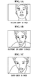
Specifically, if a mobile communication device is located below a user's face as illustrated in FIG. 1A, in front of the user's face as illustrated in FIG. 1B, or over (i.e., above) the user's face as illustrated in FIG. 1C, user's facial images captured by the mobile communication device may differ depending on the image capturing angles. As described above, if the user maintains a posture looking down on the mobile communication device, i.e., if the user's facial image is captured by the mobile communication device that is positioned below the user's face, the user's chin appears to be larger and the user's forehead appears to be narrowed. That is, the user's chin appears to be wider than normal, while the user's forehead part appears to be narrowed.
Korean Patent Unexamined Publication No. 2004-0107890 discloses an image display compensation method for a mobile phone that adjusts a captured image parallel to user's eyes by automatically performing compensation of an image tilt appearing on a display screen of the mobile phone, in accordance with a relative rotating-angle difference between the user and the display screen of the mobile phone. According to this method of operating the image capturing apparatus, the displayed information can be recognized more easily and naturally by making the image parallel to the user's eyes, irrespective of the user's motion, by performing compensation on the rotating angle of the image that is seen through the mobile phone.
However, a method or apparatus for compensating for a three-dimensional distortion occurring in the process of capturing the facial image of a user who is looking down towards the camera during the video photography is not yet available.
BRIEF SUMMARY
An aspect of the present invention provides an image capturing apparatus with image compensation and a method thereof, which can obtain an image desired by a user by determining the tilt status of a mobile communication device that captures the image of an object and performing compensation of the captured image in accordance with the determined tilt status of the device during a video telephony using the mobile communication device.
According to an aspect of the present invention, there is provided an image capturing apparatus with image compensation, the image capturing apparatus including an image capturing unit capturing an image of an object, a tilt determining unit determining a tilt of the image capturing unit against the object, and a compensation unit compensating the captured image in accordance with the determined tilt.
According to another aspect of the present invention, there is provided an image compensation method, the method including capturing an image of an object, determining a tilt of the image capturing unit relative to the object, and compensating the captured image in accordance with the determined tilt.
According to another aspect of the present invention, there is provided a video telephony apparatus including an image capturing unit in a device, having an optical axis, and movable relative to a main body of the device, a tilt sensing unit in the main body sensing a tilt of the device relative to horizontal, a tilt calculation unit calculating a tilt of the image capturing unit based on an angle between a plane in the main body and the optical axis, and a compensation unit compensating for distortion of an image captured by the image capturing unit, based on the calculated tilt.
According to another aspect of the present invention, there is provided an image compensation method, including sensing a first tilt angle which is an angle of a device in which an image capturing unit is installed relative to a horizontal plane, calculating a second tilt angle which is an angle of the image capturing unit relative to the device, capturing an image of an object and determining, based on the first and the second tilt angles, whether the image capturing unit is above the object, below the object or level with the object, and compensating for image distortion of the captured image when the image capturing unit is determined to be above or below the object.
According to other aspects of the present invention, there are provided computer-readable storage media encoded with processing instructions for causing a processor to execute the aforementioned methods.
Additional and/or other aspects and advantages of the present invention will be set forth in part in the description which follows and, in part, will be obvious from the description, or may be learned by practice of the invention.
BRIEF DESCRIPTION OF THE DRAWINGS
The above and/or other aspects and advantages of the present invention will become apparent and more readily appreciated from the following detailed description, taken in conjunction with the accompanying drawings of which:
FIGS. 1A to 1C are exemplary views illustrating images captured by a general video photography device;
FIG. 2 is a block diagram illustrating the construction of an image capturing apparatus with image compensation according to an embodiment of the present invention;
FIG. 3 is a view illustrating a tilt sensing unit according to an embodiment of the present invention;
FIG. 4 is a view illustrating an image capturing unit and a tilt sensing unit according to an embodiment of the present invention;
FIG. 5 is a view illustrating a mobile communication device that captures images of an object according to an embodiment of the present invention;
FIGS. 6A and 6B are views illustrating a captured image and a compensated image according to an embodiment of the present invention;
FIG. 7 is a view explaining divided parts of an image before being compensated according to an embodiment of the present invention;
FIG. 8 is a view explaining divided parts of a compensated image according to an embodiment of the present invention;
FIG. 9 is a view illustrating a surplus region in a display region according to an embodiment of the present invention;
FIGS. 10A to 10D are views explaining a method of processing a surplus region in a display region according to an embodiment of the present invention;
FIG. 11 is a block diagram illustrating the construction of an image capturing apparatus with image compensation according to an embodiment of the present invention;
FIG. 12 is a block diagram illustrating the construction of an image capturing apparatus with image compensation that is provided by adding a user compensation unit to the apparatus of FIG. 2;
FIG. 13 is a block diagram illustrating the construction of an image capturing apparatus with image compensation provided by adding a user compensation unit to the apparatus of FIG. 11;
FIG. 14 is a flowchart illustrating an image compensation method according to an embodiment of the present invention; and
FIG. 15 is a flowchart illustrating an image compensation method according to an embodiment of the present invention.
DETAILED DESCRIPTION OF EMBODIMENTS
Reference will now be made in detail to embodiments of the present invention, examples of which are illustrated in the accompanying drawings, wherein like reference numerals refer to the like elements throughout. The embodiments are described below in order to explain the present invention by referring to the figures.
In the description of an embodiment that follows, an image capturing apparatus with image compensation is descried as being applied to devices such as a camera and mobile communication device (e.g., a mobile phone or a personal digital assistant (PDA)) having a camera attached thereto. However, it is to be understood that these are merely non-limiting examples, and that the apparatus of the present embodiment may also be applied to, for example, a camera connected to a personal computer. Also, image compensation according to an embodiment compensates the captured image in accordance with the position of a module that captures the image of an object. And, in the present embodiment, in order to judge the position of the module that captures the image of an object, a device that can sense the tilt against a specified reference plane, such as, by way of non-limiting examples, a tilt sensor and an accelerometer, may be used, or a predetermined tilt may be used.
FIG. 2 is a block diagram illustrating the construction of an image capturing apparatus with image compensation according to an embodiment of the present invention.
As illustrated in FIG. 2, the image capturing apparatus 100 with image compensation, according to an embodiment of the present invention, includes an image capturing unit 110 capturing the image of a specified object, a tilt sensing unit 120 sensing a tilt of a device in which the image capturing unit 110 is installed, a tilt determining unit 130 determining the tilt of the image capturing unit 110 in accordance with the sensed tilt, and a compensation unit 140 performing compensation of the captured image in accordance with the determined tilt.
The image capturing apparatus 100 also includes a first storage unit 150 storing captured images and compensated images, a second storage unit 160 storing tilts sensed by the tilt sensing unit 120 and tilts determined by the tilt determining unit 130, and a transmission unit 170 transmitting the compensated image to an outside through a specified interface. In the present embodiment, the first storage unit 150, the second storage unit 160, and the transmission unit are optional.
In the description of the present embodiment that follows, the object is a person. Also, the position of the image capturing unit 110 is a position looking up at the object. In other words, the image capturing unit 110 is located below a plane on which the object is positioned and which is perpendicular to the direction of gravity. Accordingly, the image capturing unit 110 is located below the object to photograph the object. However, it is to be understood that these are merely non-limiting examples and that other orientations are contemplated.
The image capturing unit 110 may be, by way of a non-limiting example, a camera mounted in the mobile communication device, and images captured by the image capturing unit 110 may be stored in the first storage unit 150. The first storage unit 150 may be, by way of non-limiting examples, a cache, ROM, PROM, EPROM, EEPROM, flash, or SRAM. In the description of the present embodiment that follows, a flash memory, which is a nonvolatile memory, is used as the first storage unit 150.
The image capturing unit 110 is mounted in the mobile communication device. However, it is to be understood that this is merely a non-limiting example to enhance understanding of the present embodiment. The image capturing unit 110 can be applied to other devices that require the photographing of an object.
The tilt sensing unit 120 can sense the tilt of the device in which the image capturing unit 110 is installed against a specified reference plane by using a device that can sense the tilt against the specified reference plane, such as, by way of a non-limiting example, a tilt sensor and an accelerometer. In other words, if the object is a person, the image sensing unit 120 can sense the tilt between the person and the image capturing unit from a relative position between facial feature points of the person, using the image captured by the image capturing unit 110. In this case, the reference plane is a plane that is perpendicular to the direction of gravity, on the assumption that the above-described sensors are is used as measuring means. In the description of the present embodiment that follows, the reference plane is the ground. However, it is to be understood that this is merely a non-limiting example.
The tilt sensing unit 120 is installed inside the mobile communication device that is generally divided into a main body and a display device.
Now, a condition in which the tilt of the main body of the mobile communication device against the ground is sensed will be explained.
FIG. 3 is a view illustrating the tilt sensing unit 120 of FIG. 1 that senses the tilt of the main body of the mobile communication device against (i.e., relative to) the ground according to an embodiment of the present invention.
Referring to FIGS. 2 and 3, the tilt sensing unit 120 is installed in the main body 210 of the mobile communication device. The tilt sensing unit 120 senses the tilt of the main body 210 of the mobile communication device against a plane that is parallel to the ground 220. The sensed tilt is stored in the second storage unit 160. The second storage unit 160 may be, by way of non-limiting examples, a cache, ROM, PROM, EPROM, EEPROM, flash, or SRAM. In addition, the first storage unit 150 and the second storage unit are respectively constructed by hardware, but are not limited thereto. Rather, they may be, by way of a non-limiting example, integrated by hardware.
The tilt of the main body 210 of the mobile communication device against a plane that is parallel to the ground 220 is indicated “Θ1”. The use of the ground as the reference to the tilt sensed by the tilt sensing unit 120 is a non-limiting example to facilitate the understanding of the present embodiment, and the reference plane to the tilt sensed by the tilt sensing unit 120 may be changed depending on the image capturing environment. As illustrated in FIG. 3, Θ1 has a negative value against the ground 220. However, it is to be understood that Θ1 need not be negative and could have a positive value.
The tilt determining unit 130 calculates the tilt of the image capturing unit 110 in consideration of the angle between the tilt sensing unit 120 and an optical axis 111 of FIG. 4 of the image capturing unit 110, on the basis of the tilt sensing unit 120. The tilt calculated by the tilt determining unit 130 is stored in the second storage unit 160 in the same manner as the tilt sensed by the tilt sensing unit 120. The tilt of the image capturing unit 110 is calculated in consideration of the tilt sensed by the tilt sensing unit 120 and the angle between the tilt sensing unit 120 and the image capturing unit 110, and thus it can be a measure of the position of the mobile communication device on the basis of a specified object. Specifically, referring to FIGS. 2-4, the tilt determining unit 130 calculates the angle between the tilt sensing unit 120 installed in the main body 210 of the mobile communication device and the optical axis 111 of the image capturing unit 120, and then calculate the tilt of the image capturing unit 110 through the calculated angle and the tilt sensed by the tilt sensing unit 120. The angle between the image capturing unit 110 and the tilt sensing unit 120 is indicated “Θ2” as illustrated in FIG. 4. As illustrated in FIG. 4, Θ2 has a positive value against the tilt sensing unit 120. However, it is to be understood that Θ1 need not be negative and could have a positive value. Accordingly, the tilt calculated by the tilt determining unit 130 may be “Θ12”.
The compensation unit 140 determines whether the image capturing unit 110 is located over (i.e. above) the object or below the object through “Θ12” that is the tilt calculated by the tilt determining unit 130. For example, if “Θ12” is “0” on the assumption that the angle of the ground is “0”, it is determined that the optical axis of the image capturing unit 110 is parallel to the ground 220. When the tilt sensing unit 120 is installed parallel to (i.e., in front of the optical axis of the image capturing unit 110, the tilt sensed by the tilt sensing unit 120 may be considered to be the tilt of the ground reference camera. Accordingly, as illustrated in FIG. 5, it is determined that if the calculated tilt “Θ12” has a negative value, the image capturing unit 110 is located over the object 300, while if the calculated tilt “Θ12” has a positive value, the image capturing unit 110 is located below the object 300.
In the description of the present embodiment that follows, the object is a user's face, and an image of the user's face, which is desired by the user, is an image captured by the image capturing unit 110 that is located over the user's face. Also, the optical axis 111 of the image capturing unit 110 points to the user. However, it is to be understood that these are merely a non-limiting examples. Indeed, the optical axis 111 of the image capturing unit 110 may also point to an object other than the user. Accordingly, the position of the image capturing unit 110, which is determined depending on “Θ12” may be changed by the optical axis 111 of the image capturing unit 110.
If the user's face is captured by the image capturing unit 110 that is below the user's face, i.e., if “Θ12” has a positive value, the captured image is not the image desired by the user. In this case, the compensation unit 140 performs compensation of the captured image. Specifically, the compensation unit 140 determines whether the image desired by the user has been captured by comparing the tilt predetermined by the user or by default with the tilt calculated by the tilt determining unit 130, and then it determines whether to perform the compensation in accordance with the result of judgment. If the calculated tilt is determined to be an angle that causes a perspective distortion of the facial image that is not desired by the user, the compensation unit 140 compensates for the generated distortion.
Specifically, if the image capturing unit 110 that is located below the user's face has captured the user's facial image, as illustrated in FIG. 6A, the captured image may be a distorted image in which the chin part 310 appears to be emphasized and the forehead part 320 appears to be narrowed. Accordingly, the compensation unit 140 performs perspective compensation on the image as illustrated in FIG. 6A to provide a compensated image as illustrated in FIG. 6B. In the compensated image of FIG. 6B, the chin part 310 is reduced and the forehead part 320 is enlarged, in comparison to the distorted image of FIG. 6A. For example, if it is assumed that the width of the chin part 310 of FIG. 6A is “A” and the width of the chin part 310 of FIG. 6B is “B”, the relation of “A>B” is effected between them.
In the present embodiment, the image compensation may also be performed so as to decrease the shadowing effect of the image by compulsory flashing through a camera flash or heightening of the brightness of the image during the image capturing, in addition to the image modification as illustrated in FIGS. 6A and 6B.
More specifically, as illustrated in FIG. 7, the compensation unit 140 can perform the image compensation in such a manner that the captured image is divided into lattices having the same spacing in horizontal and vertical directions on an xy-plane, and as y is increased from the original point (0, 0), the width W of the image and the lattice spacing d in the vertical direction is decreased. Accordingly, the compensation unit 140 can compensate the image captured through the image capturing unit 110 of FIG. 2 located below the user's face by widening the upper part of the image, narrowing the lower part of the image, and decreasing the lattice spacing d in the vertical direction, as illustrated in FIG. 8. In other words, the compensation unit 140 performs the compensation in a manner that the captured image is divided into two specified regions having the same shape and size as those of the image before the image compensation is performed and having different positions in upward and downward directions, respectively. Accordingly, the size of the lower region of the image becomes smaller than the size of the upper region of the image.
If the region of the compensated image is different from the region on which the compensated image is displayed, i.e., if the region of the compensated image is smaller than or does not coincide with the display region, after the compensation of the captured image is performed by the compensation unit 140, the compensation unit 140 can perform another process on the empty region in order to prevent the user from arousing psychological rejection against the empty region on which no image is displayed. For example, after the compensation according to FIGS. 7 and 8 is performed, the width of the lower part of the compensated image becomes narrower than the width of the upper part thereof. Accordingly, when the display region is in the form of a square, the width of the upper part of the compensated image becomes equal to the width of the display region, but the width of the lower part of the compensated image becomes smaller than the width of the display region, thereby causing empty regions occur on both lower sides of the compensated image.
In other words, as shown in FIG. 9, the compensation unit can perform the process on an empty region 430 occurring due to the different sizes of the display region 410 and the compensated image region 420.
In the present embodiment, in order to process the empty region 430, the empty region 430 may be filled with pixel values constituting the empty region 430 of the image 440 before being compensated as shown in FIG. 10A, the empty region is filled with pixel values of the compensated image existing at the closest position in the same row, on the basis of a specified pixel in the empty region as shown in FIG. 10B, or a specified frame 450 (e.g., a picture frame) may be overlaid along the circumference of the display region 410 so that the empty region is hidden as shown in FIG. 10C. In this case, the overlay and the pixel values can be used in the case where the width of the upper part of the compensated image is equal to the width of the display region 410. If the captured image is quite larger than the display region 410, the compensated image may be cut to match (i.e., cropped) the display region 410 after the captured image is compensated as shown in FIG. 10D. In this case, it is considered that the resolution of the image captured by the image capturing unit 110 is higher than the resolution of the display region 410, and the image region that is not displayed in the display region 410 is removed after the image compensation.
In addition to the methods of processing the empty region 430 as described above with reference to FIGS. 10A to 10D, a method of cutting out an unimpaired square region of the compensated image 420, except for the empty region 430, and enlarging cut region to a size enough to fill the display region 410 is contemplated.
As described above, the methods of processing the empty region 430 occurring due to the difference in size between the display region 410 and the compensated image 420 have been explained with reference to FIGS. 10A to 10D. However, the processing of the empty region is not limited thereto.
The compensation unit 140 can perform the image compensation using a geometric transform technique and a perspective transform technique that is a kind of geometric transform technique. However, it is to be understood that these are merely non-limiting examples to facilitate the understanding of the present embodiment, and other diverse techniques can be used for the image compensation.
For reference, the perspective transform refers to typical matrix-based image transform algorithm, and the image compensation may be performed according to Equation (1). In Equation (1), “x” and “y” denote specified points of an image before the image is compensated, “x′” and “y′” denote compensated points of the image, of which the positions have been changed by the perspective transform technique, and “w” denotes a weighted value.
In the present embodiment, values of m00, m01, m02, m10, m11, m20, and m22, which are transform matrix coefficients of Equation (1), are adjusted on the basis of the ground reference tilt of the image capturing unit 110, which have been finally calculated by the tilt determining unit 130.
[ x y w ] = [ m 00 m 01 m 02 m 10 m 11 m 12 m 20 m 21 m 22 ] [ x y 1 ] x = m 00 x + m 01 y + m 02 m 20 x + m 21 y + m 22 y = m 10 x + m 11 y + m 12 m 20 x + m 21 y + m 22 X = x w , Y = y w [ Equation ( 1 ) ]
In Equation (1), “x” and “y” are coordinates of an image before the image is compensated, and “x′” and “y′” are coordinates of the compensated image. Also, it is exemplified that a 3×3 matrix is used in Equation (1), but is not limited thereto. A 2×2 matrix may also be used. In this case, a user can re-compensate the image compensated by the compensation unit 140 by changing a horizontal magnitude value m00 and a vertical magnitude value m11 that are parameters that the user can actually change through the user compensation unit 190.
The transmission unit 170 transmits the image stored in the first storage unit 150 to another user or to an external device. The transmission unit 170 may transmit the image through a wired network such as, by way of non-limiting examples, an Ethernet and universal serial bus (USB), a mobile telephone network such as CDMA, TDMA, and GSM, and a wireless network such as Bluetooth and 802.11a/b/g. In this case, the transmission unit 170 may transmit the image stored in the first storage unit 150 with/without performing a specified process of the image. If a fast transmission is required, the transmission unit directly transmits the image stored in the first storage unit 150 without processing the image. In this case, the compensated image is stored in a buffer (not illustrated), and then transmitted to an outside.
FIG. 11 is a block diagram illustrating the construction of an image capturing apparatus with image compensation according to an embodiment of the present invention.
As illustrated in FIG. 11, the image capturing apparatus 100 with image compensation, includes an image capturing unit 110 capturing the image of a specified object, a tilt storage unit 180 storing information about predetermined tilts of the image capturing unit 110, a tilt determining unit 130 determining the tilt of the image capturing unit 110 in accordance with the stored tilt information, and a compensation unit 140 performing compensation of the captured image in accordance with the determined tilt.
Unlike the image capturing apparatus 100 with image compensation of FIG. 2, the image capturing apparatus 100 with image compensation of FIG. 11 does not sense the tilt, but uses the predetermined tilt. In other words, the tilt information stored in the tilt storage unit 180 can be experimentally obtained from attitudes typically taken when the apparatus including the image capturing unit 110 is used. In addition, the tilt information stored in the tilt storage unit 180 may be stored in the manufacturing process or through a firmware upgrade later, but the storage of the tilt information is not limited thereto.
Constituent elements of FIG. 11 identified by the same reference numerals as those in FIG. 2 have the same functions, and thus duplicate explanations thereof are omitted.
However, unlike the tilt determining unit 130 of FIG. 2, the tilt determining unit 130 of FIG. 11 determines the tilt of the image capturing unit 110 by using the tilt information stored in the tilt storage unit 180.
As described above, with reference to FIGS. 2 and 11, the compensation unit 140 may perform compensation of an image captured by the image capturing unit 110 in accordance with the tilt determined by the tilt determining unit 130. However, a user may directly perform compensation according to the user's propensity and taste, after the compensation is performed by the compensation unit 140 can be further compensated as desired.
For this, the image capturing apparatus as illustrated in FIGS. 2 and 11 may further include a user compensation unit 190, whereby a user can directly compensate an image as illustrated in FIGS. 12 and 13. In this case, if the image capturing apparatus 100 is a mobile communication device, the user compensation unit 190 may be a button installed in the mobile communication device. Accordingly, the user can obtain an image suitable for the user by re-compensating the image once compensated by the compensation unit 140. At this time, by changing the parameters m00 and m00 that are parameters of Equation (1) through the user compensation unit 140, the image once compensated by the compensation unit 140.
For example, if a user desires that the face of a person appears to be more nicely tapered in a state that m00=0.7 according to the tilt determined by the tilt determining unit 130, on the assumption that the object is a person, he/she can change the state of m00=0.7 to m00=0.8 through the user compensation unit 190. If a user uses the mobile communication device when the mobile communication device is located over the face in comparison to most users, the user can change m11=0.90, according to the tilt determined by the tilt determining unit 130, to m11=0.8 through the user compensation unit 190.
FIG. 14 is a flowchart illustrating a method of operating an image capturing apparatus with image compensation according to an embodiment of the present invention. This method is described with concurrent reference to the apparatus of FIG. 2 for ease of explanation only.
As illustrated in FIG. 14, according to the method of operating the image capturing apparatus according to the present embodiment, the tilt sensing unit 120 senses the tilt of the device in which the image capturing unit 110 is installed (operation S110). In the description of the present embodiment that follows, the image capturing unit 110 is a camera installed in the mobile communication device, and the tilt sensing unit 120 is installed in the main body 210 of the mobile communication terminal. Accordingly, the tilt sensing unit 120 senses the tilt of the main body 210 of the mobile communication device against the ground 220 and the sensed tilt is stored in the second storage unit 160, as described above. However, it is to be understood that a camera is but one non-limiting example.
The tilt determining unit 130 calculates the tilt of the image capturing unit 110 in consideration of the angle between the tilt sensing unit 120 and the optical axis of the image capturing unit 110 (operation S120). The calculated tilt may be stored in the second storage unit 160 in the same manner as the sensed tilt.
Then, the compensation unit 140 determines whether the image has been captured through the image capturing unit 110 (operation S130). In other words, the compensation unit determines whether the image captured by the image capturing unit 110 through a user's manipulation has been stored in the first storage unit 150.
In addition, the compensation unit 140 determines whether distortion has occurred in the captured image through the tilt of the image capturing unit 110 (operation S140). In the description of the present embodiment that follows, the user desires to capture the upper image of the object through the image capturing unit 110, and thus the compensation unit 140 determines whether the image capturing unit 110 is located over the object or below the object on the basis of the tilt of the image capturing unit 110.
If the image is not captured at a position desired by the user as a result of judgment, the compensation unit 140 performs compensation of the image stored in the first storage unit 150 by using the perspective transform technique and so on (operation S150). For example, if the image is captured at a position that is below the user's face as illustrated in FIG. 6A, although the user desires to capture the image at a position that is over the user's face, the compensation unit performs the compensation of the image stored in the first storage unit 150, as illustrated in FIG. 6A, using the perspective transform technique.
If the image compensation is completed, the compensation unit 140 stores the compensated image in the first storage unit 150 (operation S160).
Thereafter, the user can contemplate communications by setting the display screen of the user's mobile communication device or transmitting the user's image to another user.
At this time, if the user desires to re-compensate the image having been compensated by the compensation unit 140 (operation S170), he/she can re-compensate the image through the user compensation unit 190 (operation S180).
FIG. 15 is a flowchart illustrating a method of operating an image capturing apparatus with image compensation according to an embodiment of the present invention. This method is described with concurrent reference to the apparatus of FIG. 11 for ease of explanation only.
As illustrated in FIG. 15, according to the video telephony device with image compensation according to the present embodiment, the tilt determining unit determines the tilt of the image capturing unit 110 with reference to the tilt information stored in the tilt storage unit 180 (operation S210).
Then, the compensation unit 140 determines whether the image is captured through the image capturing unit 110 (operation S220). In other words, the compensation unit 140 determines whether the image captured by the image capturing unit 110 through the user's manipulation is stored in the first storage unit 150.
If the image of the object is captured by the image capturing unit 110, the compensation unit 140 performs compensation of the captured image with reference to the determined tilt (operation S230).
If the compensation of the image is completed, the compensation unit 140 re-stores the compensated imaged in the first storage unit 150 (operation S240).
At this time, if the user desires to re-compensate the image having been compensated by the compensation unit 140 (operation S250), he/she can re-compensate the image stored in the compensation unit 140 through the user compensation unit 190 (operation S260).
In the image capturing apparatus with image compensation and the method of operating the image capturing apparatus according to the above described embodiments of the present invention, the term “unit”, as used herein, means, but is not limited to, a software or hardware component, such as a Field Programmable Gate Array (FPGA) or Application Specific Integrated Circuit (ASIC), which performs certain tasks. A unit may advantageously be configured to reside on the addressable storage medium and configured to execute on one or more processors. Thus, a unit may include, by way of example, components, such as software components, object-oriented software components, class components and task components, processes, functions, attributes, procedures, subroutines, segments of program code, drivers, firmware, microcode, circuitry, data, databases, data structures, tables, arrays, and variables. The functionality provided for in the components and units may be combined into fewer components and units or further separated into additional components and units.
In the foregoing descriptions of embodiments of the present invention, reference was made to accompanying drawings illustrating block diagrams and flowcharts. It is to be understood that each block of the flowchart illustrations, and combinations of blocks in the flowchart illustrations, can be implemented by computer program instructions. These computer program instructions can be provided to a processor of a general purpose computer, special purpose computer, or other programmable data processing apparatus to produce a machine, such that the instructions, which execute via the processor of the computer or other programmable data processing apparatus, create means for implementing the functions specified in the flowchart block or blocks.
These computer program instructions may also be stored in a computer usable or computer-readable memory that can direct a computer or other programmable data processing apparatus to function in a particular manner, such that the instructions stored in the computer usable or computer-readable memory produce an article of manufacture including instruction means that implement the function specified in the flowchart block or blocks.
The computer program instructions may also be loaded onto a computer or other programmable data processing apparatus to cause a series of operational processes to be performed on the computer or other programmable apparatus to produce a computer implemented process such that the instructions that execute on the computer or other programmable apparatus provide operations for implementing the functions specified in the flowchart block or blocks.
Also, each block of the flowchart illustrations may represent a module, segment, or portion of code, which comprises one or more executable instructions for implementing the specified logical function(s). It should also be noted that in some alternative implementations, the functions noted in the blocks may occur in an order that differs from those described and/or illustrated. For example, two blocks shown in succession may in fact be executed substantially concurrently or the blocks may sometimes be executed in the reverse order, depending upon the functionality involved.
According to the image capturing apparatus with image compensation and the method of operating the image capturing apparatus according to the above-described embodiments of the present invention, the distortion of a user's facial image occurring due to the capturing angle of the camera is compensated for even if the user keeps an unaffected posture during the video telephony through a mobile communication device, the psychological rejection to the facial image that is seen by an opposite party can be minimized to promote the spread of video photography devices.
Although a few embodiments of the present invention have been shown and described, the present invention is not limited to the described embodiments. Instead, it would be appreciated by those skilled in the art that changes may be made to these embodiments without departing from the principles and spirit of the invention, the scope of which is defined by the claims and their equivalents.

Claims (39)

What is claimed is:
1. An image capturing apparatus comprising:
a main body;
an image capturer to capture an image of an object, the image capturer having an optical axis pointing to the object;
an image sensor device adapted for sensing a tilt of the image capturer relative to the object, wherein if the object is a person, the image sensor device senses the tilt from a relative position between facial feature points of the person, using the image captured by the image capturer;
a tilt determiner to determine the tilt of the image capturer relative to the object; and
a compensator adapted for determining whether the image capturer is located above the object or below the object on the basis of the tilt, and for compensating image distortion of the captured image when the image capturer is determined to be above or below the object, using at least one processor.
2. The image capturing apparatus of claim 1, wherein the object is a person.
3. The image capturing apparatus of claim 1, wherein the image capturer captures the image of the object from a position below the object.
4. The image capturing apparatus of claim 1, wherein the tilt sensor device senses the tilt between a person and the image capturer from a relative position between facial feature points of the person, using the image captured by the image capturer.
5. The image capturing apparatus of claim 1, further comprising:
a first storage to store the image captured by the image capturer; and
a second storage to store information about the sensed tilt and the determined tilt.
6. The image capturing apparatus of claim 1, further comprising:
a tilt sensor device to sense a tilt of a device in which the image capturer is installed, relative to a reference plane, which is perpendicular to a direction of gravity, using an inertial sensor.
7. The image capturing apparatus of claim 1, wherein the tilt determiner selects one of the stored tilts as the tilt of the image capturer.
8. The image capturing apparatus of claim 1, wherein the compensator determines whether to perform the compensation of the captured image and a level of compensation using the tilt determined by the tilt determiner.
9. The image capturing apparatus of claim 8, wherein the compensator compensates the captured image through a geometric transform technique.
10. The image capturing apparatus of claim 9, wherein the compensator adjusts transform matrix coefficients used for the image compensation using the determined tilt.
11. The image capturing apparatus of claim 9, wherein the compensator uses a perspective transform technique among the geometric transform technique of the captured image.
12. The image capturing apparatus of claim 9, wherein, when the captured image is transformed through the geometric transform technique, the compensator performs compensation so that two specified regions, which have a same shape and area as those of the image before being compensated and have different positions in upward and downward directions, respectively, are determined, and an area of a region at a relatively low position is smaller than an area of a region at a relatively high position.
13. The image capturing apparatus of claim 1, further comprising a user compensator to adjust a degree of the image compensation performed in the compensator by receiving a user's change of the determined tilt or a compensation level determined by the compensator.
14. The image capturing apparatus of claim 9, further comprising a display unit to display the image compensated by the compensator,
wherein, when a region of the compensated image does not coincide with a display region of the display unit, and an empty region having no image is displayed, the compensator performs a process on the empty region.
15. The image capturing apparatus of claim 14, wherein the compensator fills the empty region with image pixel values constituting the corresponding region in the image before being compensated.
16. The image capturing apparatus of claim 14, wherein the compensator fills the empty region with pixel values of the compensated image existing at the closest position in a same row, on a basis of a specified pixel in the empty region.
17. The image capturing apparatus of claim 14, wherein the compensator overlays a specified frame over a circumference of the display region so as to hide the empty region.
18. The image capturing apparatus of claim 14, wherein, when the image capturer captures an image that is larger than the display region, the compensator compensates the image and then crops the compensated image to match the display region.
19. The image capturing apparatus of claim 14, wherein the compensator cuts out the region of the compensated image from the display region, in the form of a square, and then enlarges the cut region of the compensated image to a size enough to fill the display region.
20. An image compensation method, the method comprising:
capturing an image of an object, by an image capturer relative to the object having an optical axis pointing to the object;
sensing a tilt of the image capturer relative to the object, wherein if the object is a person, an image sensor device senses the tilt from a relative position between facial feature points of the person, using the image captured by the image capturer;
determining the tilt of the image capturer relative to the object;
determining whether the image capturer is located above the object or below the object on the basis of the tilt;
compensating image distortion of the captured image when the image capturer is determined to be above or below the object, and
wherein the method is performed using at least one processor.
21. The method of claim 20, wherein the object is a person.
22. The method of claim 20, wherein the capturing comprises capturing the image of the object from a position below the object.
23. The method of claim 20, wherein, in the sensing, a tilt between a person and the image capturer from a relative position between facial feature points of the person is sensed, using the captured image.
24. The method of claim 20, further comprising:
storing the captured image; and
storing information about the sensed tilt and the determined tilt.
25. The method of claim 20, further comprising sensing a tilt of a device in which the image capturer is installed, relative to a reference plane, which is perpendicular to a direction of gravity, using an inertial sensor.
26. The method of claim 20, wherein the compensating comprises determining whether to perform the compensation of the captured image and a level of compensation using the determined tilt.
27. The method of claim 26, wherein, in the compensating, the captured image is compensated through a geometric transform technique.
28. The method of claim 27, wherein the compensating comprises adjusting transform matrix coefficients used for the image compensation using the determined tilt.
29. The method of claim 27, wherein, in the compensating, the captured image is compensated through a perspective transform technique among the geometric transform technique of the captured image.
30. The method of claim 27, wherein, in the compensating, when the captured image is compensated through the geometric transform technique, the compensating is performed so that two specified regions, which have a same shape and area as those of the image before being compensated and have different positions in upward and downward directions, respectively, are determined, and an area of a region at a relatively low position is smaller than an area of a region at a relatively high position.
31. The method of claim 20, further comprising adjusting a degree of the image compensation by enabling a user to change the determined tilt or a determined compensation level.
32. The method of claim 27, wherein, when a region of the compensated image does not coincide with a display region on which the compensated image is displayed, and thus an empty region having no image is displayed, the compensating comprises performing a process on the empty region.
33. The method of claim 32, wherein, in the compensating, the empty region is filled with image pixel values constituting the corresponding region in the image before being compensated.
34. The method of claim 32, wherein, in the compensating, the empty region is filled with pixel values of the compensated image existing at the closet position in a same row, on a basis of a specified pixel in the empty region.
35. The method of claim 32, wherein the compensating comprises overlaying a specified frame over a circumference of the display region so as to hide the empty region.
36. The method of claim 32, wherein, when an image that is larger than the display region is captured, the compensating comprises compensating the image and then cropping the compensated image to match the display region.
37. The method of claim 32, wherein the compensating comprises cutting out the region, except for the empty region from the compensated image, in the form of a square, and then enlarging the cut region to a size enough to fill the display region.
38. A non-transitory computer-readable storage medium encoded with processing instructions for causing at least one processor to execute a method comprising:
capturing an image of an object, by an image capturer relative to the object having an optical axis pointing to the object;
sensing a tilt of the image capturer relative to the object, wherein if the object is a person, an image sensor device senses the tilt from a relative position between facial feature points of the person, using the image captured by the image capturer;
determining the tilt of the image capturer relative to the object;
determining whether the image capturer is located above the object or below the object on the basis of the tilt; and
compensating image distortion of the captured image when the image capturer is determined to be above or below the object, and
wherein the method is performed using at least one processor.
39. An image capturing apparatus comprising:
a main body;
an image capturer to capture an image of an object;
a tilt determiner to determine a tilt of the image capturer relative to the object;
a compensator to compensate the captured image using the determined tilt of the image capturer relative to the object, using at least one processor; and
a tilt sensor device to sense a tilt of a device in which the image capturer is installed,
wherein the tilt determiner determines the tilt of the image capturer relative to the object using an angle between the main body and a reference plane, and using an angle between the tilt sensor device and an optical axis of the image capturer,
wherein the captured image includes a first part and a second part and is divided into lattices having a same spacing in horizontal and vertical directions, and the compensator compensates the captured image by widening the first part of the image, narrowing the second part of the image, and decreasing the lattice spacing in the vertical direction.
US11/525,055 2005-09-22 2006-09-22 Image capturing apparatus with image compensation and method thereof Expired - Fee Related US8842935B2 (en)

Applications Claiming Priority (4)

Application Number Priority Date Filing Date Title
KR10-2005-0088356 2005-09-22
KR20050088356 2005-09-22
KR10-2006-0084321 2006-09-01
KR1020060084321A KR100818989B1 (en) 2005-09-22 2006-09-01 Apparatus for video photography with image compensation and operating method for the same

Publications (2)

Publication Number Publication Date
US20070065039A1 US20070065039A1 (en) 2007-03-22
US8842935B2 true US8842935B2 (en) 2014-09-23

Family

ID=37627221

Family Applications (1)

Application Number Title Priority Date Filing Date
US11/525,055 Expired - Fee Related US8842935B2 (en) 2005-09-22 2006-09-22 Image capturing apparatus with image compensation and method thereof

Country Status (4)

Country Link
US (1) US8842935B2 (en)
EP (1) EP1768387B1 (en)
JP (1) JP4377399B2 (en)
CN (1) CN1937716B (en)

Cited By (2)

* Cited by examiner, † Cited by third party
Publication number Priority date Publication date Assignee Title
US10275863B2 (en) * 2015-04-03 2019-04-30 Cognex Corporation Homography rectification
US20200065602A1 (en) * 2018-08-27 2020-02-27 Daon Holdings Limited Methods and systems for capturing image data

Families Citing this family (35)

* Cited by examiner, † Cited by third party
Publication number Priority date Publication date Assignee Title
EP1768387B1 (en) * 2005-09-22 2014-11-05 Samsung Electronics Co., Ltd. Image capturing apparatus with image compensation and method therefor
JP4344888B2 (en) * 2005-12-09 2009-10-14 株式会社カシオ日立モバイルコミュニケーションズ Imaging apparatus, captured image processing method, and program
DE202006014883U1 (en) * 2006-09-26 2008-02-07 Corimage Ag Recording system, camera and angle sensor for a camera
JP4286292B2 (en) * 2007-01-30 2009-06-24 三洋電機株式会社 Electronic camera
US8174555B2 (en) 2007-05-30 2012-05-08 Eastman Kodak Company Portable video communication system
US7391442B1 (en) 2007-11-01 2008-06-24 International Business Machines Corporation Digital camera including a distortion correction system
CN101650627B (en) * 2008-08-14 2011-02-02 鸿富锦精密工业(深圳)有限公司 Electronic equipment and operating control method
EP2166510B1 (en) * 2008-09-18 2018-03-28 Delphi Technologies, Inc. Method for calculating the position and orientation of a camera in a vehicle
JP5166230B2 (en) * 2008-12-26 2013-03-21 富士フイルム株式会社 Image processing apparatus and method, and program
US8599238B2 (en) * 2009-10-16 2013-12-03 Apple Inc. Facial pose improvement with perspective distortion correction
JP5413250B2 (en) 2010-03-05 2014-02-12 ソニー株式会社 Image processing apparatus, image processing method, and program
TWI432021B (en) * 2011-01-27 2014-03-21 Altek Corp Image capturing device and image correction method thereof
US9035940B2 (en) * 2011-03-08 2015-05-19 Nokia Corporation Apparatus and associated methods
US20120249792A1 (en) * 2011-04-01 2012-10-04 Qualcomm Incorporated Dynamic image stabilization for mobile/portable electronic devices
US9204047B2 (en) 2011-04-08 2015-12-01 Nokia Technologies Oy Imaging
CN104011766B (en) * 2011-12-20 2017-08-11 惠普发展公司,有限责任合伙企业 Image data transformation based on customer location
US9398262B2 (en) * 2011-12-29 2016-07-19 Intel Corporation Communication using avatar
WO2013152453A1 (en) 2012-04-09 2013-10-17 Intel Corporation Communication using interactive avatars
US20140055339A1 (en) * 2012-08-22 2014-02-27 David Stanasolovich Adaptive visual output based on motion compensation of a mobile device
KR101978214B1 (en) 2012-11-19 2019-05-14 엘지전자 주식회사 Display device for displaying video and method thereof
CN104065911B (en) * 2013-03-18 2019-01-15 联想(北京)有限公司 Display control method and device
WO2014153689A1 (en) 2013-03-29 2014-10-02 Intel Corporation Avatar animation, social networking and touch screen applications
JP5971216B2 (en) * 2013-09-20 2016-08-17 カシオ計算機株式会社 Image processing apparatus, image processing method, and program
KR102086510B1 (en) * 2013-09-26 2020-04-14 엘지전자 주식회사 A head mounted display and the method of controlling the same
CN103824252A (en) * 2014-02-10 2014-05-28 安徽科大讯飞信息科技股份有限公司 Picture processing method and system
JP6032252B2 (en) * 2014-09-09 2016-11-24 カシオ計算機株式会社 Image correction apparatus, image correction method, and program
JP6320251B2 (en) * 2014-09-09 2018-05-09 オリンパス株式会社 Imaging apparatus, imaging method, and program
US9830728B2 (en) 2014-12-23 2017-11-28 Intel Corporation Augmented facial animation
JP2016127419A (en) * 2014-12-26 2016-07-11 カシオ計算機株式会社 Image correction device, image correction method, and program
KR102317820B1 (en) * 2015-08-12 2021-10-26 삼성전자주식회사 Method for processing image and electronic device supporting the same
WO2017101094A1 (en) 2015-12-18 2017-06-22 Intel Corporation Avatar animation system
CN107092853A (en) * 2016-02-17 2017-08-25 中兴通讯股份有限公司 Photographic method and device
JP2018011172A (en) * 2016-07-13 2018-01-18 株式会社リコー Imaging apparatus, imaging system and program
CN107607204A (en) * 2017-09-05 2018-01-19 昆山博威泰克电子科技有限公司 Color analysis device and method
CN109618097B (en) * 2018-12-29 2021-03-16 维沃移动通信有限公司 Auxiliary photographing method and terminal equipment

Citations (41)

* Cited by examiner, † Cited by third party
Publication number Priority date Publication date Assignee Title
JPS6265567A (en) 1985-09-17 1987-03-24 Nippon Telegr & Teleph Corp <Ntt> Method for correcting picture distortion
US5742853A (en) * 1994-06-09 1998-04-21 Asahi Kogaku Kogyo Kabushiki Kaisha Information setting and display device for a camera
US5831746A (en) * 1993-02-25 1998-11-03 Ohio Electronic Engravers, Inc. Engraved area volume measurement system and method using pixel data
JPH1196346A (en) 1997-09-22 1999-04-09 Konica Corp Image processing method and image processor
US5982952A (en) * 1995-09-28 1999-11-09 Nec Corporation Optical character reader with tangent detection for detecting tilt of image data
KR20000054209A (en) 2000-05-26 2000-09-05 서상인 A Face Model Enhancement Service on the Internet and Mobile Video Phone
US6314211B1 (en) * 1997-12-30 2001-11-06 Samsung Electronics Co., Ltd. Apparatus and method for converting two-dimensional image sequence into three-dimensional image using conversion of motion disparity into horizontal disparity and post-processing method during generation of three-dimensional image
WO2002037179A2 (en) 2000-11-01 2002-05-10 Koninklijke Philips Electronics N.V. Method and apparatus for tracking an object using a camera in a hand-held processing device
US6392693B1 (en) * 1998-09-03 2002-05-21 Matsushita Electric Industrial Co., Ltd. Monitoring video camera apparatus
US20020118292A1 (en) * 2001-02-28 2002-08-29 Baron John M. System and method for removal of digital image vertical distortion
JP2002281150A (en) 2001-03-21 2002-09-27 Sony Corp Mobile information terminal device
US20030016883A1 (en) * 2001-07-20 2003-01-23 Baron John M. System and method for horizon correction within images
US20030090476A1 (en) * 1999-05-25 2003-05-15 Paul Lapstun Orientation sensing device with identifier
US20030125008A1 (en) * 2001-12-28 2003-07-03 Nec Corporation Portable electronic equipment having a photographing function
GB2384381A (en) 2002-01-17 2003-07-23 James Leigh Taylor Camera incorporating tilt sensor
US20030231243A1 (en) * 2002-06-18 2003-12-18 Casio Computer Co., Ltd. Digital camera and photographing direction acquisition method
JP2004030251A (en) 2002-06-26 2004-01-29 Fuji Photo Film Co Ltd Image data transmitting method, mobile terminal device and program
US6704048B1 (en) * 1998-08-27 2004-03-09 Polycom, Inc. Adaptive electronic zoom control
JP2004147138A (en) 2002-10-25 2004-05-20 Kyocera Corp Automatic camera movement compensation device for electronic camera
US20040125073A1 (en) * 2002-12-30 2004-07-01 Scott Potter Portable electronic apparatus and method employing motion sensor for function control
JP2004242208A (en) 2003-02-07 2004-08-26 Nec Saitama Ltd Mobile communication terminal device and image correction program
US20040203535A1 (en) * 2003-04-14 2004-10-14 Samsung Electronics Co., Ltd. Mobile phone having a rotational camera lens housing
US6820980B1 (en) * 2001-03-23 2004-11-23 Panavision, Inc. Automatic pan and tilt compensation system for a camera support structure
US20040257752A1 (en) * 2003-06-16 2004-12-23 Lg Electronics Inc. Portable terminal
KR20040107890A (en) 2003-06-14 2004-12-23 엘지전자 주식회사 Image slope control method of mobile phone
US20050058367A1 (en) * 2002-02-15 2005-03-17 Fujitsu Limited Image transformation method and apparatus, image recognition apparatus, robot control apparatus and image projection apparatus
US20050104968A1 (en) * 2003-03-18 2005-05-19 Fujitsu Limited Capture device
US20050207671A1 (en) * 2003-04-11 2005-09-22 Tadashi Saito Data presentation device
US20050264653A1 (en) * 2004-05-27 2005-12-01 Starkweather James A Portable electronic device with adjustable image capture orientation and method therefore
US20050281443A1 (en) * 2003-12-19 2005-12-22 Fujitsu Limited Information processing unit
US20060055778A1 (en) * 2004-09-15 2006-03-16 Elmo Co., Ltd. Surveillance camera system
US20060238502A1 (en) * 2003-10-28 2006-10-26 Katsuhiro Kanamori Image display device and image display method
US20070065039A1 (en) * 2005-09-22 2007-03-22 Samsung Electronics Co., Ltd. Image capturing apparatus with image compensation and method thereof
US20070081818A1 (en) * 2005-10-06 2007-04-12 Motorola, Inc. Integrated selectively angled camera for clam style products
US20070101382A1 (en) * 2005-10-31 2007-05-03 Hitachi Kokusai Electric Inc. Node management system and node managing program using sensing system
US7272253B2 (en) * 2001-02-09 2007-09-18 Hitachi, Ltd. Method for non-destructive inspection, apparatus thereof and digital camera system
US7486837B2 (en) * 2004-12-07 2009-02-03 Panasonic Corporation Method, device, and program for image conversion, method, device and program for texture mapping, and server-client system
US7515178B1 (en) * 2007-11-01 2009-04-07 International Business Machines Corporation Method of correcting distortions in digital images captured by a digital camera system
US7539334B2 (en) * 2005-09-06 2009-05-26 Intel Corporation Method and apparatus for identifying mole growth
US20090284463A1 (en) * 2008-05-13 2009-11-19 Yukako Morimoto Information processing apparatus, information processing method, information processing program, and mobile terminal
US20110149094A1 (en) * 2009-12-22 2011-06-23 Apple Inc. Image capture device having tilt and/or perspective correction

Family Cites Families (1)

* Cited by examiner, † Cited by third party
Publication number Priority date Publication date Assignee Title
JP2003036059A (en) * 2001-07-24 2003-02-07 Nec Saitama Ltd Gradation-adjustment liquid-crystal display device

Patent Citations (47)

* Cited by examiner, † Cited by third party
Publication number Priority date Publication date Assignee Title
JPS6265567A (en) 1985-09-17 1987-03-24 Nippon Telegr & Teleph Corp <Ntt> Method for correcting picture distortion
US5831746A (en) * 1993-02-25 1998-11-03 Ohio Electronic Engravers, Inc. Engraved area volume measurement system and method using pixel data
US5742853A (en) * 1994-06-09 1998-04-21 Asahi Kogaku Kogyo Kabushiki Kaisha Information setting and display device for a camera
US5982952A (en) * 1995-09-28 1999-11-09 Nec Corporation Optical character reader with tangent detection for detecting tilt of image data
JPH1196346A (en) 1997-09-22 1999-04-09 Konica Corp Image processing method and image processor
US6314211B1 (en) * 1997-12-30 2001-11-06 Samsung Electronics Co., Ltd. Apparatus and method for converting two-dimensional image sequence into three-dimensional image using conversion of motion disparity into horizontal disparity and post-processing method during generation of three-dimensional image
US6704048B1 (en) * 1998-08-27 2004-03-09 Polycom, Inc. Adaptive electronic zoom control
US6392693B1 (en) * 1998-09-03 2002-05-21 Matsushita Electric Industrial Co., Ltd. Monitoring video camera apparatus
US20030090476A1 (en) * 1999-05-25 2003-05-15 Paul Lapstun Orientation sensing device with identifier
US20030090475A1 (en) * 1999-05-25 2003-05-15 Lapstun Paul Orientation sensing device for use with coded marks
KR20000054209A (en) 2000-05-26 2000-09-05 서상인 A Face Model Enhancement Service on the Internet and Mobile Video Phone
WO2002037179A2 (en) 2000-11-01 2002-05-10 Koninklijke Philips Electronics N.V. Method and apparatus for tracking an object using a camera in a hand-held processing device
US7272253B2 (en) * 2001-02-09 2007-09-18 Hitachi, Ltd. Method for non-destructive inspection, apparatus thereof and digital camera system
US6963365B2 (en) * 2001-02-28 2005-11-08 Hewlett-Packard Development Company, L.P. System and method for removal of digital image vertical distortion
JP2002335438A (en) 2001-02-28 2002-11-22 Hewlett Packard Co <Hp> Digital camera for removal of digital image perspective distortion
US20020118292A1 (en) * 2001-02-28 2002-08-29 Baron John M. System and method for removal of digital image vertical distortion
JP2002281150A (en) 2001-03-21 2002-09-27 Sony Corp Mobile information terminal device
US6820980B1 (en) * 2001-03-23 2004-11-23 Panavision, Inc. Automatic pan and tilt compensation system for a camera support structure
US20030016883A1 (en) * 2001-07-20 2003-01-23 Baron John M. System and method for horizon correction within images
US20030125008A1 (en) * 2001-12-28 2003-07-03 Nec Corporation Portable electronic equipment having a photographing function
GB2384381A (en) 2002-01-17 2003-07-23 James Leigh Taylor Camera incorporating tilt sensor
US7561754B2 (en) * 2002-02-15 2009-07-14 Fujitsu Limited Image transformation apparatus for image transformation of projected image by preventing distortion
US20080212896A1 (en) * 2002-02-15 2008-09-04 Fujitsu Limited Image transformation method and apparatus, image recognition apparatus, robot control apparatus and image projection apparatus
US20050058367A1 (en) * 2002-02-15 2005-03-17 Fujitsu Limited Image transformation method and apparatus, image recognition apparatus, robot control apparatus and image projection apparatus
US20030231243A1 (en) * 2002-06-18 2003-12-18 Casio Computer Co., Ltd. Digital camera and photographing direction acquisition method
JP2004030251A (en) 2002-06-26 2004-01-29 Fuji Photo Film Co Ltd Image data transmitting method, mobile terminal device and program
JP2004147138A (en) 2002-10-25 2004-05-20 Kyocera Corp Automatic camera movement compensation device for electronic camera
US20040125073A1 (en) * 2002-12-30 2004-07-01 Scott Potter Portable electronic apparatus and method employing motion sensor for function control
JP2004242208A (en) 2003-02-07 2004-08-26 Nec Saitama Ltd Mobile communication terminal device and image correction program
US20050104968A1 (en) * 2003-03-18 2005-05-19 Fujitsu Limited Capture device
US20050207671A1 (en) * 2003-04-11 2005-09-22 Tadashi Saito Data presentation device
US20040203535A1 (en) * 2003-04-14 2004-10-14 Samsung Electronics Co., Ltd. Mobile phone having a rotational camera lens housing
KR20040107890A (en) 2003-06-14 2004-12-23 엘지전자 주식회사 Image slope control method of mobile phone
US7155118B2 (en) * 2003-06-16 2006-12-26 Lg Electronics Inc. Portable terminal
US20040257752A1 (en) * 2003-06-16 2004-12-23 Lg Electronics Inc. Portable terminal
US20060238502A1 (en) * 2003-10-28 2006-10-26 Katsuhiro Kanamori Image display device and image display method
US20050281443A1 (en) * 2003-12-19 2005-12-22 Fujitsu Limited Information processing unit
US20050264653A1 (en) * 2004-05-27 2005-12-01 Starkweather James A Portable electronic device with adjustable image capture orientation and method therefore
US20060055778A1 (en) * 2004-09-15 2006-03-16 Elmo Co., Ltd. Surveillance camera system
US7486837B2 (en) * 2004-12-07 2009-02-03 Panasonic Corporation Method, device, and program for image conversion, method, device and program for texture mapping, and server-client system
US7539334B2 (en) * 2005-09-06 2009-05-26 Intel Corporation Method and apparatus for identifying mole growth
US20070065039A1 (en) * 2005-09-22 2007-03-22 Samsung Electronics Co., Ltd. Image capturing apparatus with image compensation and method thereof
US20070081818A1 (en) * 2005-10-06 2007-04-12 Motorola, Inc. Integrated selectively angled camera for clam style products
US20070101382A1 (en) * 2005-10-31 2007-05-03 Hitachi Kokusai Electric Inc. Node management system and node managing program using sensing system
US7515178B1 (en) * 2007-11-01 2009-04-07 International Business Machines Corporation Method of correcting distortions in digital images captured by a digital camera system
US20090284463A1 (en) * 2008-05-13 2009-11-19 Yukako Morimoto Information processing apparatus, information processing method, information processing program, and mobile terminal
US20110149094A1 (en) * 2009-12-22 2011-06-23 Apple Inc. Image capture device having tilt and/or perspective correction

Non-Patent Citations (4)

* Cited by examiner, † Cited by third party
Title
Ahn, Jung-Hyeok, "The image slope control method of the cellular phone", Dec. 23, 2004, English Translation of Korean Unexamined Patent Applicaton Publication No. 10-2004-0107890, p. 1-8. *
Chinese Office Action dated Jan. 4, 2008 issued in corresponding Chinese Patent Application.
Japanese Office Action dated May 20, 2008 issued in corresponding Japanese Patent Application No. 2006-257543.
Office Action issued in corresponding Korean Patent Application No. 10- 2006-0084321, on Sep. 28, 2007.

Cited By (3)

* Cited by examiner, † Cited by third party
Publication number Priority date Publication date Assignee Title
US10275863B2 (en) * 2015-04-03 2019-04-30 Cognex Corporation Homography rectification
US20200065602A1 (en) * 2018-08-27 2020-02-27 Daon Holdings Limited Methods and systems for capturing image data
US10970576B2 (en) * 2018-08-27 2021-04-06 Daon Holdings Limited Methods and systems for capturing image data

Also Published As

Publication number Publication date
JP4377399B2 (en) 2009-12-02
JP2007089183A (en) 2007-04-05
EP1768387B1 (en) 2014-11-05
CN1937716A (en) 2007-03-28
US20070065039A1 (en) 2007-03-22
CN1937716B (en) 2011-07-13
EP1768387A1 (en) 2007-03-28

Similar Documents

Publication Publication Date Title
US8842935B2 (en) Image capturing apparatus with image compensation and method thereof
JP5659305B2 (en) Image generating apparatus and image generating method
JP5659304B2 (en) Image generating apparatus and image generating method
JP5769813B2 (en) Image generating apparatus and image generating method
JP5865388B2 (en) Image generating apparatus and image generating method
US9158969B2 (en) Information processing device, server system, image processing system, and information storage device
WO2015135477A1 (en) Handheld terminal and screen anti-shake method and device for handheld terminal
JP6899875B2 (en) Information processing device, video display system, information processing device control method, and program
CN111064895B (en) Virtual shooting method and electronic equipment
US9277201B2 (en) Image processing device and method, and imaging device
CN109936697B (en) Video shooting target tracking method and device
US10462358B2 (en) Information processing apparatus, information processing system, and information processing method
WO2012157546A1 (en) Projector
JP2019080243A (en) Imaging apparatus, method for controlling imaging apparatus, and program
CN111083371A (en) Shooting method and electronic equipment
WO2018196854A1 (en) Photographing method, photographing apparatus and mobile terminal
US8593543B2 (en) Imaging apparatus
KR100818989B1 (en) Apparatus for video photography with image compensation and operating method for the same
CN115225806A (en) Cinematic image framing for wide field of view (FOV) cameras
JP2007166529A (en) Video telephone system
JP2008053833A (en) Information processor, control program for image correction, and image correcting method of information processor
JP2005311872A (en) Electronic equipment, program and recording medium
JP5603671B2 (en) Electronic device, imaging method, and image conversion program
JP3845407B2 (en) Mobile terminal and imaging recording method
WO2020124504A1 (en) Image quality optimization method, display device and medium

Legal Events

Date Code Title Description
AS Assignment

Owner name: SAMSUNG ELECTRONICS CO., LTD., KOREA, REPUBLIC OF

Free format text: ASSIGNMENT OF ASSIGNORS INTEREST;ASSIGNORS:PARK, TAE-SUH;KIM, YEUN-BAE;PARK, MIN-KYU;REEL/FRAME:018339/0819

Effective date: 20060918

STCF Information on status: patent grant

Free format text: PATENTED CASE

FEPP Fee payment procedure

Free format text: PAYOR NUMBER ASSIGNED (ORIGINAL EVENT CODE: ASPN); ENTITY STATUS OF PATENT OWNER: LARGE ENTITY

MAFP Maintenance fee payment

Free format text: PAYMENT OF MAINTENANCE FEE, 4TH YEAR, LARGE ENTITY (ORIGINAL EVENT CODE: M1551)

Year of fee payment: 4

FEPP Fee payment procedure

Free format text: MAINTENANCE FEE REMINDER MAILED (ORIGINAL EVENT CODE: REM.); ENTITY STATUS OF PATENT OWNER: LARGE ENTITY

LAPS Lapse for failure to pay maintenance fees

Free format text: PATENT EXPIRED FOR FAILURE TO PAY MAINTENANCE FEES (ORIGINAL EVENT CODE: EXP.); ENTITY STATUS OF PATENT OWNER: LARGE ENTITY

STCH Information on status: patent discontinuation

Free format text: PATENT EXPIRED DUE TO NONPAYMENT OF MAINTENANCE FEES UNDER 37 CFR 1.362

FP Lapsed due to failure to pay maintenance fee

Effective date: 20220923